Secure Substation Design Guide
Available Languages
Bias-Free Language
The documentation set for this product strives to use bias-free language. For the purposes of this documentation set, bias-free is defined as language that does not imply discrimination based on age, disability, gender, racial identity, ethnic identity, sexual orientation, socioeconomic status, and intersectionality. Exceptions may be present in the documentation due to language that is hardcoded in the user interfaces of the product software, language used based on RFP documentation, or language that is used by a referenced third-party product. Learn more about how Cisco is using Inclusive Language.
- US/Canada 800-553-2447
- Worldwide Support Phone Numbers
- All Tools
 Feedback
 Feedback
Secure Substation Design Guide Overview
What The Design Guide Establishes
Chapter 2 Secure Substation Solution Overview
Security and Compliance Drivers
Substation Deployment Profiles
Chapter 3 Substation Security Reference Architecture
Supported Products and Software Releases
Station Bus, Electronic Security Perimeter, and Process Bus Scope
Multiservice, Corporate, and Field Area Network Zones
Control Center, Security Operations Center, and WAN Components
NOC, Catalyst WAN Manager and Substation Spoke Model
Security Zones, Secure Conduits, VRFs, and Service VPNs
Workforce Enablement and Management Service Models
Chapter 4 Security Design Principles
Standards Alignment for Transmission Substations
Defense-in-Depth for Substation Environments
Electronic Security Perimeter Boundary Protection
WAN Encryption and Transport Options
Integrated Firewall and Discrete Firewall Design Guidance
NGFW, ZBFW, IDS, and IPS Placement
SCADA Protocol Inspection and Custom DNP3 Rules
Network Access Control with 802.1X and MAB
Resiliency, High Availability, and Failure Modes
Logging, Monitoring, and Time Synchronization
Chapter 5 WAN Edge Aggregation and Service Segmentation Architecture
Northbound and Southbound Connectivity
WAN Edge Aggregation at Data Center routers
WAN Edge Scaling and Deployment Considerations
Summary of Architectural Considerations
Platform Considerations for Data Center Hub Routers:
NAT requirements for Mixed Transport
Data Centre Hub Router - Throughput Sizing and Capacity Planning
Platform Selection Recommendation
Platform Selection Scenarios (Scale vs. Throughput)
Platform Selection - Scenario-Based Examples
Headend Redundancy and Traffic Steering Models
Active/Standby Headend Architecture (Deterministic Path)
Active/Active Headend Architecture (Load-Sharing)
Active/Active vs Active/Standby - Architectural Comparison Summary
Chapter 6 Medium Substation Design
Validated Medium Substation Topology
Design Option 1: Integrated Firewall
Integrated Firewall Implementation
Design Option 2: Discrete Firewall
Discrete Firewall Design Considerations
WAN Aggregation for the Medium Substation
Northbound and Southbound Connectivity
Service VPN Architecture for Medium Substation
Service VPN/VRF to Zone-Based Firewall Zone Mapping
Firewall and Threat Inspection Placement
Raw Socket Transport for Legacy Serial Devices
Network Access Control for LAN-Side Devices
Cyber Vision Sensor Placement and East-West Visibility
Traffic Profile and Scale Considerations
Medium Substation Design Summary
Chapter 7 Small Substation Design
Network Segmentation and Service VPNs:
Service Flows using service VPN:
Secure Substation – small – Various service Flows:
Secure Substation – small – Switch Management Service:
This path is mapped to the SEC-OPS-MGMT-SVC service VPN
Secure Substation – small – Physical Security and VOIP Services:
Secure Substation – small – Workforce Enablement:
SCADA Service flow using Service VPN:
1. Native IP-Based SCADA Communication
2. Legacy Serial SCADA Transport via Raw Sockets
3. High Availability with Dual Raw Socket Connectivity:
The Substation Router as an Integrated Firewall for SCADA:
Visibility and Threat Detection (Cisco Cyber Vision)
Traffic Profile considered for small substation:
Chapter 8 Firewall and Threat Inspection Design
NGFW Design for IR8340 Deployments
Cyber Vision Architecture for Substation Security
Sensor Placement on IE9300 and IE3505 Platforms
East-West Visibility within the ESP
North-South Visibility for SCADA Traffic
OT Asset Vulnerability Visibility
Baseline Creation and Change Reporting
Cyber Vision Deployment Guidance by Substation Model
Chapter 10 Validated Design Summary
Validated Architecture Building Blocks
Appendix A Reference Documents
Cisco Validated Design and Solution References
Cisco Catalyst WAN and Security References
Industry Standards and Protocol References
Secure Substation Design Guide Overview
The Secure Substation design guide is a Cisco Validated Design reference. It guides the construction of secure, segmented, and observable utility substations across large transmission, medium distribution, and compact field-site profiles.
The design brings together ruggedized routing and switching, Cisco SD-WAN segmentation, Cisco Cyber Vision visibility, and policy-driven security controls into a repeatable substation blueprint. It organizes the content around the network behaviors utilities need to preserve:
● Deterministic SCADA reachability.
● Resilient WAN transport.
● Bounded management access.
● Monitored OT assets.
● Controlled paths for higher-bandwidth services such as PMU and physical-security video.
The design uses three deployment models so the same principles apply based on the site type:
● Large substations with dual-router resilience.
● Medium substations with a single rugged WAN edge.
● Small substations using compact IR1101-based routing.
Each tier ties back to service VPN separation, WAN sizing, Cyber Vision telemetry, and security policy placement.
Substations are no longer isolated serial environments.
Modern utility sites carry SCADA, management, telemetry, PMU, video, and remote-support traffic across shared IP infrastructure while still needing deterministic operations, cyber separation, and auditable security controls.
This design guide gives engineering, OT operations, and security teams a common reference for turning those requirements into a repeatable architecture.
● This guide shows you where to apply inspection, and how to:
● Structure the substation edge.
● Separate critical services.
● Size the WAN for large, medium, and small sites.
Key reasons to read the design guide:
● Reduce design ambiguity: Align network, OT, and security teams around one validated blueprint instead of one-off substation builds.
● Protect critical operations: Preserve SCADA reachability while adding segmentation, firewall policy, application recognition, and inspection where it matters.
● Plan before deployment: Relate traffic types, bandwidth assumptions, and product choices before configuration begins.
● Improve audit readiness: Map architecture decisions to zoning, access control, monitoring, and operational evidence expected in regulated utility environments.
Cisco brings the substation WAN, industrial LAN, security policy, and OT visibility layers into one architecture.
Secure substations need more than a router, a switch, or an IPS rule in isolation.
They need those controls to work together across the full lifecycle.
Cisco capabilities used in this design guide
Rugged OT infrastructure: Industrial routers and switches such as IR8340, IR1101, IE9300, IE3100, and IE3500 support hardened deployment models for utility environments.
SD-WAN and segmentation:
● Cisco SD-WAN provides centralized overlay policy.
● It enables service VPN separation.
● It delivers encrypted transport.
● It supports scalable operations for many substations.
Security policy at the edge:
● Zone-based firewall.
● Application-aware policy.
● NBAR.
● Snort IDS/IPS capabilities.
These capabilities can align to the same traffic paths shown in the architecture.
OT visibility:
● Cisco Cyber Vision adds asset context.
● It adds protocol context.
● It adds anomaly context.
This context ensures policy decisions are informed by what is actually running in the substation.
What The Design Guide Establishes
The design guide establishes a repeatable design model for:
● Service separation: SCADA, MultiService, and Management traffic are treated as distinct service VPNs with different trust, QoS, and inspection requirements.
● Substation profiles: Large, medium, and small designs map platform choices to expected device scale, traffic volume, and resiliency needs.
● Operational visibility: Cyber Vision sensors and center connectivity provide asset discovery, protocol awareness, and anomaly context across OT zones.
● Security alignment: NERC CIP impact categories, NGFW policy, NBAR application recognition, and Snort IPS are positioned against the architecture.
The intended outcomes are:
● Standardize the substation edge: Use a common routing, switching, and SD-WAN pattern while still sizing the design for large, medium, and small facilities.
● Protect critical OT paths: Constrain SCADA, management, and multiservice flows using:
◦ Segmentation
◦ Zone-based firewalling
◦ Application matching
◦ IPS inspection where required
● Plan WAN capacity: Relate traffic types to practical bandwidth and QoS assumptions, including:
◦ DNP3
◦ PMU
◦ CCTV.
◦ Enterprise access
◦ Management telemetry
● Connect design to deployment: Carry the same architecture into platform references and configuration examples for:
◦ Routers
◦ Switches
◦ Security functions
Chapter 2 Secure Substation Solution Overview
This chapter provides a high-level overview of the Cisco Secure Substation solution for small and medium transmission substations.
The intent is to introduce the solution scope, security objectives, deployment profiles, and traffic categories without duplicating the detailed reference architecture and security design guidance covered in later chapters.
The solution is designed for utilities that need to modernize substation communications while maintaining reliable grid operations and improving cybersecurity posture.
It supports:
● SCADA monitoring and control.
● Station bus communications.
● Phasor measurement use cases where required.
● Physical security services.
● Management access.
● Workforce enablement.
● Integration with centralized control center and security operations environments.
The Secure Substation architecture uses ruggedized Cisco industrial routers and switches to provide:
● Secure WAN aggregation.
● Station LAN connectivity.
● Segmentation.
● Firewall enforcement.
● Industrial visibility.
● Flexible management.
Small substations use a compact spoke model, while medium substations support higher device counts, additional zones, and broader service separation.
Both profiles use the same architectural principles so that deployment and operations can remain consistent across the utility.
The primary objective of the solution is to protect transmission substation communications without disrupting grid operations.
The design provides a repeatable framework for connecting substations to utility headend services while separating traffic by function, trust level, and operational requirement.
At a high level, the solution supports the following objectives:
● Secure aggregation of substation LAN traffic at the WAN edge.
● Segmentation using VRFs, VLANs, firewall zones, and service VPNs.
● Electronic Security Perimeter boundary protection for protected OT assets.
● Support for SCADA and station bus protocols such as DNP3, IEC 60870-5-104, Modbus TCP, and IEC 61850 MMS where applicable.
● Integrate legacy serial devices using raw socket or serial pseudowire options where required.
● Use Cisco Cyber Vision for industrial asset visibility and east-west traffic monitoring.
● Use Catalyst WAN Manager for centralized WAN lifecycle operations, with autonomous operation supported where appropriate.
● Align with NERC CIP and ISA/IEC 62443 principles for transmission substation environments.
Security and Compliance Drivers
Security requirements for transmission substation automation are strongly influenced by NERC CIP and ISA/IEC 62443.
NERC CIP drives the need to:
● Identify protected cyber assets
● Define Electronic Security Perimeters
● Control routable communications
● Manage remote access
● Monitor security events
● Maintain configuration baselines
● Support evidence-oriented operations
ISA/IEC 62443 complements this approach through defense-in-depth, zones and conduits, risk-based segmentation, and lifecycle security practices for industrial automation and control systems.
In the Secure Substation solution, these concepts are reflected through:
● Logical zones
● Controlled service paths
● Firewall boundaries
● Visibility tooling
● Separation of SCADA, management, physical security, enterprise, and workforce services
The solution provides capabilities that support alignment with these frameworks.
However, compliance depends on:
● The utility's asset classification
● Regulatory scope
● Configuration standards
● Operating procedures
● Documentation
● Audit practices
Chapter 3 covers the detailed reference architecture, including zones, conduits, VRFs, service VPNs, WAN components, and traffic mapping. Chapter 4 covers the security principles used to protect and monitor those services.
Substation Deployment Profiles
The Secure Substation solution supports small and medium transmission substation deployment profiles. These profiles provide a high-level view of expected scale, traffic characteristics, and platform alignment. Detailed design guidance for each profile is covered in the respective design chapters.
The small substation profile is based on the Cisco IR1101 platform. It provides a compact single-router model for small transmission substations in the 115-230 kV range, where device count and segmentation needs are lower than medium transmission sites but still require secure WAN connectivity, visibility, and controlled access.
Small transmission sites may include:
● SCADA endpoints
● Station bus devices
● Legacy serial RTUs
● Physical security services
● Workforce enablement endpoints
● Management services
● Typical point count: 200-600 points.
● Average throughput without PMUs: 50-200 kbps.
● Additional PMU throughput: approximately 5-10 Mbps per PMU when PMUs are deployed.
● Typical WAN provisioning: 1-10 Mbps using microwave, fiber, or MPLS.
● Common protocols: DNP3, IEC 61850 MMS where applicable to station bus use cases, and ICCP for tie-lines.
The small substation profile supports the following core solution capabilities:
● SCADA aggregation
● VRF or service VPN separation
● VLAN segmentation
● Firewall policy
● Legacy serial integration
● Cyber Vision visibility
● Catalyst WAN Manager-based or autonomous operation
The medium substation profile uses the Cisco IR8340 Substation WAN Router. It provides a higher-scale spoke model for medium transmission substations in the 345-500 kV range, where the number of IEDs, service zones, operational systems, and control center integrations is typically greater.
Medium transmission sites may include:
● A larger station LAN
● SCADA and station bus services
● PMU or synchrophasor flows where required
● Physical security systems
● Workforce enablement
● Management services
● Legacy serial connectivity
● Typical point count: 500-1,500 points.
● Average throughput without PMUs: 0.5-2 Mbps.
● Additional PMU throughput: approximately 5-10 Mbps per PMU when PMUs are deployed.
● Typical WAN provisioning: 10-50 Mbps using fiber or high-capacity microwave.
● Common protocols: IEC 61850 MMS, DNP3, ICCP, and IEEE C37.118 for PMU traffic.
The medium substation profile can support integrated firewall services on the IR8340 or a discrete firewall at the ESP boundary. The detailed design options for medium substations are covered in the medium substation design chapter.
Many transmission substations include a mix of modern Ethernet-connected devices and legacy serial equipment. The Secure Substation solution supports phased migration by allowing legacy RTUs and serial-connected devices to remain operational while the site transitions toward a segmented Ethernet-based architecture.
From an operations perspective, the common architecture allows utilities to standardize WAN connectivity, zone mapping, service VPNs, management access, monitoring, and remote-access workflows across multiple sites. Catalyst WAN Manager can provide centralized lifecycle operations for larger deployments, while autonomous operation can be used where centralized management is not required or not yet available.
Large and EHV substations, process bus design, IEC 61850 GOOSE/Sampled Values engineering, and advanced large-substation timing and redundancy models are outside this version of the design guide unless explicitly included in a later design scope.
The Cisco Secure Substation solution provides a repeatable framework for securing small and medium transmission substations. It combines ruggedized routing and switching, service separation, ESP boundary protection, firewall enforcement, Cyber Vision visibility, legacy integration, and flexible management options.
This chapter introduced the solution at a high level. Chapter 3 defines the Substation Security Reference Architecture, and Chapter 4 defines the Security Design Principles used to protect the architecture.
Chapter 3 Substation Security Reference Architecture
This chapter describes the Secure Substation reference architecture for small and medium substations. The purpose of the chapter is to establish the major architectural building blocks, logical zones, WAN model, service VPNs, traffic classes, and operational domains used throughout the design guide. Detailed security design principles, policy enforcement methods, access-control behavior, and protocol-specific protection guidance are covered in the next chapter.
The reference architecture uses a hub-and-spoke model. Centralized services reside in the OT data center, security operations center, network operations center, and related utility operations environments. Each substation operates as a spoke that aggregates local traffic, connects to the utility WAN through a WAN edge router, and maps local services into the appropriate logical zones and service VPNs. This model provides a repeatable structure that can be applied across small and medium substations while allowing each site to scale according to device count, available WAN transport, and operational requirements.
The architecture separates traffic by operational function. SCADA monitoring and control, station bus services, phasor measurement, physical security, management, workforce access, enterprise integration, and field area network communications are represented as distinct architectural domains. These domains are connected through defined conduits and mapped to VRFs or service VPNs where logical separation is required.
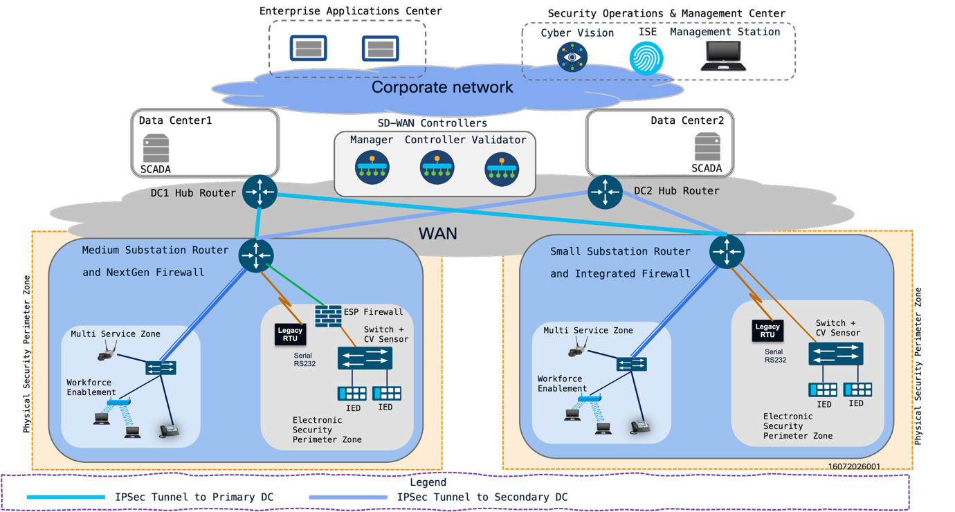 |
The Secure Substation reference architecture is organized around the following operational building blocks:
● OT (TSO/DSO) data center: Hosts SCADA, control center applications, data center WAN edge hubs, and OT services used for transmission substation operations.
● Security Operations Center: Hosts or consumes security monitoring services such as Cisco Cyber Vision, security telemetry, event correlation, and incident response workflows.
● Network Operations Center: Hosts Catalyst WAN Manager and related WAN control components used for onboarding, policy distribution, monitoring, and WAN lifecycle operations.
● WAN edge routers and transport: Provide the hub-and-spoke connectivity between data centers and substations. Cisco Catalyst 8000 Series platforms act as data center WAN edge hubs, while substation routers act as spokes.
● Substation Layer: Contains the local WAN edge router, industrial Ethernet switches, station bus devices, ESP assets, physical security endpoints, workforce enablement services, management interfaces, and legacy serial devices.
The OT data center, SOC, and NOC may be physically co-located or operated as separate environments. The reference architecture treats them as distinct logical domains because they have different operational roles. The OT data center is focused on grid operations, the SOC is focused on monitoring and response, and the NOC is focused on WAN and infrastructure operations.
WAN transport provides connectivity between substations and centralized utility locations. The architecture is transport-flexible and may use private circuits, utility-owned fiber, cellular, internet transport with encryption, or a combination of services. The WAN carries multiple logical services between the substation and utility data centers, rather than acting as a single flat network extension.
At the substation, the medium profile uses the Cisco IR8340 as the substation WAN edge router. The small substation uses the Cisco IR1101 as the compact WAN edge router. Industrial Ethernet switches provide station LAN connectivity and may support Cisco Cyber Vision sensor functions for asset visibility. The reference diagrams show IE9300 or IE3x00 switching in the medium profile and IE3100 switching in the small profile.
Substation endpoints include legacy RTUs connected through RS-232 serial interfaces, IEDs, protection relays, gateways, PMUs, cameras, badge readers, door controllers, remote desktop systems, engineering workstations, network infrastructure, and local management systems. These endpoints are grouped into security zones based on their operational function and communication requirements.
Supported Products and Software Releases
Table 1. Supported products and software releases
| Architecture area |
Product or platform |
Function in the design |
Validated software release |
| Headend WAN edge |
Cisco Catalyst 8000 Series Edge Platforms |
Data center hub routing, WAN aggregation, IPsec termination, substation aggregation |
26.2.1 |
| Medium substation WAN edge |
Cisco IR8340 |
Substation WAN router, service aggregation, segmentation, serial integration |
26.2.1 |
| Small substation WAN edge |
Cisco IR1101 |
Compact substation WAN router, service aggregation, segmentation, serial integration |
26.2.1 |
| Medium substation switching |
Cisco IE9300 or IE3x00 Industrial Ethernet switches |
Station LAN connectivity, VLAN separation, Cyber Vision sensor support |
26.2.1 |
| Small substation switching |
Cisco IE3100 Industrial Ethernet switches |
Compact station LAN connectivity, VLAN separation |
26.2.1 |
| Small substation switching |
Cisco IE3505 Industrial Ethernet switches |
Compact station ESP LAN connectivity, Cyber Vision sensor support, VLAN separation. |
26.2.1 |
| Industrial visibility |
Cisco Cyber Vision |
Asset discovery, industrial protocol visibility, traffic monitoring |
26.2.1 |
| WAN management |
Cisco Catalyst WAN Manager |
WAN policy, device onboarding, monitoring, and lifecycle management |
26.2.1 |
| WAN overlay control components |
Manager, Controller, and Validator components |
Overlay control, orchestration, and secure WAN operation |
26.2.1 |
| Security inspection |
IR8340 |
ESP boundary and zone inspection functions using NGFW,etc.Integrated router security or discrete firewall |
26.2.1 |
| Identity and access services |
Cisco ISE or utility-approved identity platform |
Device and user identity services |
26.2.1 |
| Security operations |
SIEM, SOC tools, and Cisco security integrations |
Event collection, correlation, and incident monitoring |
26.2.1 |
Station Bus, Electronic Security Perimeter, and Process Bus Scope
For this version of the design guide, the substation LAN is primarily described through the station bus and the Electronic Security Perimeter. Process bus is referenced only as a scope boundary because large substation deployment is not included in this release of the design.
The station bus connects the systems used for automation, monitoring, control, and local engineering functions. Typical station bus endpoints include RTUs, IEDs, protection relays, gateways, bay controllers, local HMIs, engineering workstations, and SCADA communication devices. Station bus traffic may include DNP3, IEC 60870-5-104, Modbus TCP, IEC 61850 MMS, SNMP, syslog, SSH, HTTPS, and file-transfer traffic.
The Electronic Security Perimeter represents the logical boundary around protected cyber assets. In the reference architecture, ESP placement is described at the architectural level so that Chapter 4 can define the associated security principles, policy controls, and access methods.
Process bus architectures are predominantly associated with large digital substations that use IEC 61850 GOOSE and Sampled Values for high-speed protection and process-level communications. These designs introduce strict timing, latency, redundancy, and validation requirements. Because large substation deployment is outside this design guide version, IEC 61850 GOOSE/SV process bus design is excluded from the validated reference architecture.
Multiservice, Corporate, and Field Area Network Zones
The reference architecture recognizes that substations carry more than traditional SCADA traffic. Physical security, environmental monitoring, workforce access, enterprise services, and field area network communications may also be present. These services are represented as separate architectural zones so they can be mapped cleanly into the WAN and headend model.
The multiservice zone represents non-SCADA operational services that support substation operations. This may include video surveillance, access control, environmental monitoring, local maintenance systems, or other operational support services.
The corporate zone represents approved enterprise services that may need to exchange information with substation systems or supporting infrastructure. Examples include identity services, logging platforms, inventory systems, patch repositories, and enterprise management applications.
The Field Area Network zone represents communication with devices outside the substation fence or distributed across the utility field network. FAN endpoints may include reclosers, capacitor banks, distribution automation devices, meters, sensors, or other remote assets. FAN placement in the architecture depends on the utility topology and the relationship between the substation and the broader field network.
Control Center, Security Operations Center, and WAN Components
The control center is the primary operational destination for SCADA monitoring and control. It may host SCADA masters, energy management systems, distribution management systems, historian services, operator consoles, and operational data collection systems. In the reference architecture, the control center is a headend destination for SCADA service VPN traffic and related operational data flows.
The Security Operations Center provides centralized monitoring and incident response functions. SOC systems may receive logs, events, Cyber Vision alerts, firewall events, authentication events, and network telemetry. The SOC is represented as a monitoring and response domain connected through defined management or security service paths.
WAN components provide the transport and aggregation layer between substations and centralized utility environments. These components may include substation WAN routers, Cisco Catalyst 8000 Series data center WAN edge routers, firewalls, private circuits, internet transport, cellular transport, microwave transport, and WAN overlay components managed through Catalyst WAN Manager.
The reference data center design uses two data center locations. Data Center 1 and Data Center 2 can each host SCADA services and a Catalyst 8000 Series WAN edge router operating as a hub. The same data center pair can aggregate both small and medium substations. The security center, including Cisco Cyber Vision and Cisco ISE, can be co-located with one data center or operated as a separate security services location, depending on the utility operations model.
NOC, Catalyst WAN Manager and Substation Spoke Model
Together, the NOC, Catalyst WAN Manager, and substation spoke model provide the operational framework for managing WAN connectivity across multiple substations. Catalyst WAN Manager is used for device onboarding, policy distribution, monitoring, and lifecycle management of the WAN environment.
In this model, each substation router operates as a spoke. The spoke connects local substation zones to the WAN overlay and advertises the service VPNs or VRFs that are required for that site. The OT data center WAN edge hubs aggregate these services and provide connectivity to control center systems, SOC tools, management platforms, enterprise services, and other authorized destinations.
The spoke model supports different substation sizes. Small substations typically use a compact set of zones and service VPNs. Medium substations may use additional segmentation, more local endpoints, and optional dedicated security components. Both models use the same architectural vocabulary so that design, deployment, and operations remain consistent across the utility.
The data center aggregation model is active/active across two data centers. Catalyst WAN Manager and the associated Manager, Controller, and Validator components provide the WAN management and control functions. These components do not have to be physically co-located with the data center WAN edge routers. Data center WAN edge router selection should account for the number of substation spokes, IPsec session scale, and aggregate crypto throughput required by the combined small and medium substation population. Hub scale is handled through the active/active data center model and data center WAN edge capacity; IKEv2 cluster load balancing is not treated as a baseline design assumption for this design guide version.
Security Zones, Secure Conduits, VRFs, and Service VPNs
Security zones group systems with similar function, ownership, or trust level. Secure conduits describe the communication paths between zones. VRFs and service VPNs provide the logical routing separation used to carry these services across the substation LAN and utility WAN.
A typical small or medium substation may include the following zones:
● ESP or protected OT zone for applicable OT assets inside the Electronic Security Perimeter, including station bus systems, automation devices, protection relays, RTUs, IEDs, and local operational systems..
● OT SCADA zone for monitoring and control services.
● Multiservice zone for local non-SCADA operational services such as remote desktop, local applications, or supporting utility services.
● Physical security zone for cameras, badge readers, door controllers, and video systems.
● Management zone for infrastructure administration and telemetry.
● Workforce enablement zone for controlled engineering and field technician access.
● Corporate services zone for approved enterprise integrations.
The mapping between zones, conduits, VRFs, and service VPNs is a key output of the reference architecture. For example, SCADA monitoring and control can be mapped to a SCADA service VPN, physical security can be mapped to one or more physical security service VPNs, and management or workforce access can be mapped to separate service models. Chapter 3 defines this architectural model;
Chapter 4 defines the security principles used to protect these communication paths.
Workforce Enablement and Management Service Models
Workforce enablement represents access for field technicians, protection engineers, maintenance teams, and approved vendors. The architecture treats workforce access as a defined service model rather than an implicit path into the station bus. This allows user access to be described separately from SCADA control and infrastructure management.
Management services include infrastructure administration, telemetry, logging, authentication, software lifecycle functions, configuration backup, and monitoring. These services may use a dedicated management zone, management VRF, or management service VPN depending on the deployment model.
Separating workforce enablement from management services gives the architecture a clearer operational structure. Field access, vendor support, and infrastructure administration can then be documented as separate services with separate destinations and ownership.
The reference architecture recognizes five major traffic profiles: SCADA, PMU, physical security, enterprise, and management. These profiles help determine how services are grouped into zones, conduits, VRFs, and service VPNs.
SCADA traffic supports monitoring and control between the substation and control center. Common protocols include DNP3, IEC 60870-5-104, Modbus TCP, and utility-approved SCADA communications between SCADA masters, RTUs, gateways, and IED-facing systems.
PMU traffic supports synchrophasor and wide-area measurement use cases where deployed. PMU traffic may use IEEE C37.118 and is represented separately from traditional SCADA because its bandwidth, timing, and delivery characteristics can differ from polling-based control traffic.
Physical security traffic includes video, alarms, access control, door status, badge systems, and related monitoring. Enterprise traffic represents approved IT or business-system interaction with substation services. Management traffic includes administration, telemetry, logging, backup, authentication, and software lifecycle functions.
IEC 61850 MMS may be present on the station bus for monitoring, control, and configuration use cases. IEC 61850 GOOSE and Sampled Values are process bus services associated primarily with large digital substations and are not part of the validated small and medium substation architecture in this design guide version.
Chapter 3 identifies where traffic and protocols appear in the architecture. Detailed performance, prioritization, inspection, access-control, and protocol-specific security decisions are intentionally deferred to the Security Design Principles chapter and implementation chapters.
The Substation Security Reference Architecture provides a generalized model for securing small and medium substations. It defines the OT data center, SOC, NOC, WAN edge router roles, Catalyst WAN Manager role, station bus scope, ESP placement, WAN components, zones, conduits, VRFs, service VPNs, traffic profiles, and operational domains.
The next chapter builds on this model by defining the security design principles used to protect the zones, conduits, protocols, service VPNs, and operational workflows introduced here.
Chapter 4 Security Design Principles
This chapter defines the security design principles used by the Secure Substation architecture for small and medium transmission substation deployments. It builds on the reference architecture introduced in Chapter 3 and focuses on how the architecture should be protected, monitored, and operated.
The design principles align with the intent of NERC CIP and ISA/IEC 62443. NERC CIP drives protection of Bulk Electric System Cyber Systems, Electronic Security Perimeter boundary protection, secure remote access, monitoring, change management, and evidence-oriented operations. ISA/IEC 62443 provides a complementary industrial cybersecurity model based on defense-in-depth, zones and conduits, risk-based segmentation, and lifecycle security for industrial automation and control systems.
The guidance in this chapter supports alignment with those frameworks, but it does not by itself establish compliance. Final compliance depends on the utility's asset classification, regulatory scope, documented processes, configuration baselines, operating procedures, evidence retention, and audit practices.
Standards Alignment for Transmission Substations
Transmission substations can include cyber assets that are subject to NERC CIP applicability decisions. The design should therefore support clear identification of protected assets, controlled communication paths, auditable access, and consistent monitoring. The architecture should also preserve operational reliability for SCADA monitoring and control, protection engineering, phasor measurement, physical security, and management functions.
NERC CIP alignment is primarily reflected through the following design outcomes:
● Defined Electronic Security Perimeter boundaries for protected substation cyber assets.
● Controlled routable communication into and out of protected zones.
● Secure handling of remote access and vendor access paths.
● Monitoring of security-relevant events at ESP boundaries and management points.
● Segregation of management access from operational control traffic.
● Configuration and change-management support through documented baselines.
● Logging, time synchronization, and evidence collection to support operations and audits.
ISA/IEC 62443 alignment is reflected through the zone-and-conduit model. Substation services are grouped into zones based on function, risk, and trust level. Communication between zones is represented as conduits and protected using segmentation, firewall policy, monitoring, identity controls, and management processes. The result is a layered architecture in which no single control is expected to protect the environment by itself.
Defense-in-Depth for Substation Environments
Defense-in-depth is the core security principle for the Secure Substation design. Transmission substations require layered controls because the environment includes a mix of legacy and modern devices, operational protocols, remote access needs, physical security systems, and centralized management.
The defense-in-depth model includes the following layers:
● Physical protection of substation assets, cabinets, cabling, and network infrastructure.
● Network segmentation using zones, conduits, VRFs, VLANs, and service VPNs.
● Boundary protection at the ESP and other zone transitions.
● Identity-based access for users and devices where supported.
● Firewall enforcement and protocol-aware inspection for approved conduits.
● Industrial visibility using Cisco Cyber Vision and related monitoring systems.
● Logging, alerting, and time synchronization for operational and audit evidence.
● Change control, configuration management, and vulnerability management processes.
● Resiliency and failure-mode planning for WAN, firewall, and management dependencies.
This layered approach supports both NERC CIP and IEC 62443. NERC CIP emphasizes controlled access, monitoring, and evidence for applicable systems. IEC 62443 emphasizes zones, conduits, and risk-based security requirements across people, process, and technology.
Electronic Security Perimeter Boundary Protection
The Electronic Security Perimeter (ESP) is the logical boundary around protected substation cyber assets. ESP placement should be based on asset classification, communication requirements, and the utility's regulatory scope. For transmission substations, the ESP commonly includes systems that participate in SCADA monitoring and control, station bus communications, and other protected OT services.
Boundary protection should establish clear access points into and out of the ESP. These access points may be enforced by an integrated firewall on the substation router, a discrete firewall, access control lists, VRF separation, service VPNs, or a combination of controls. The design should identify which systems communicate across the boundary, why the communication is required, which protocols are used, and which devices enforce the policy.
ESP boundary controls should support the following outcomes:
● Known and documented communication paths.
● Separation of SCADA, management, physical security, workforce, and enterprise services.
● Controlled access from control center systems to approved substation endpoints.
● Separation of management interfaces from operational control paths.
● Monitoring of traffic entering and leaving protected zones.
● Ability to produce architecture, configuration, and monitoring evidence.
The ESP model should be simple enough to operate consistently. A design with too many exceptions or undocumented conduits becomes difficult to audit, troubleshoot, and defend.
WAN Encryption and Transport Options
Transmission substations may connect to the OT data center, SOC, NOC, and related utility operations environments using fiber, microwave, MPLS, carrier Ethernet, cellular, private circuits, internet transport, or a combination of transports. The transport choice affects bandwidth, latency, availability, and encryption requirements.
The Secure Substation design treats the WAN as a shared transport for multiple logical services. Service separation is maintained using VRFs, service VPNs, routing policy, encryption, and firewall controls. When traffic crosses untrusted or shared infrastructure, encryption should be used to protect confidentiality and integrity. IPsec is commonly used for encrypted WAN overlay connectivity between substation spokes and OT data center WAN edge hubs.
WAN encryption design should account for:
● Primary and secondary data center paths.
● IPsec tunnel scale across small and medium substation populations.
● Aggregate crypto throughput on Catalyst 8000 Series OT data center WAN edge routers.
● Substation router platform capacity.
● Certificate, key, and lifecycle management.
● Transport failure and reconvergence behavior.
● Monitoring of tunnel state and WAN path availability.
Private transport does not eliminate the need for segmentation or monitoring. Even when fiber or MPLS is used, the architecture should preserve separation between SCADA, management, physical security, enterprise, workforce, and FAN services.
Integrated Firewall and Discrete Firewall Design Guidance
The Secure Substation architecture supports integrated and discrete firewall models. Both models can be valid for transmission substation deployments, but they create different operational and failure-domain tradeoffs.
In the integrated firewall model, the substation router provides routing, WAN connectivity, segmentation, and firewall enforcement. This model reduces device count, simplifies site footprint, and is well suited to compact small and medium substations. It also simplifies cabling and can reduce operational complexity when policies are centrally managed.
In the discrete firewall model, a separate firewall is placed at the ESP boundary or between major substation zones. This model can provide clearer separation between routing and security functions, additional inspection capacity, and more granular firewall administration. It may be preferred where the utility requires dedicated firewall operations, expanded NGFW features, or separate change-control ownership for security policy.
The selection between integrated and discrete firewall should consider:
● Substation size and expected traffic volume.
● Number of zones and conduits.
● Required inspection depth.
● ESP boundary placement.
● Availability and failover requirements.
● Space, power, and environmental constraints.
● Operational ownership between network and security teams.
● Evidence and audit expectations for boundary controls.
The design should avoid mixing firewall models without a clear operational reason. Consistency across sites reduces troubleshooting complexity and improves auditability.
NGFW, ZBFW, IDS, and IPS Placement
Firewall and inspection functions should be placed where they can enforce the intended zone and conduit model. The appropriate placement depends on whether the deployment uses integrated firewall services or a discrete firewall.
Zone-Based Firewall is commonly used to enforce policy between logical zones on the substation WAN edge router. It is useful for controlling traffic between SCADA, management, physical security, enterprise, workforce, and WAN-facing services. ZBFW policy should align to the VRF, VLAN, and service VPN structure defined in the reference architecture.
Next-generation firewall capabilities can be integrated into the substation WAN edge router or deployed on a discrete firewall. NGFW placement is most useful at boundaries where application visibility, threat inspection, and policy enforcement are required. For transmission substations, this commonly includes the ESP boundary, remote access paths, management conduits, and enterprise-to-OT conduits.
Cisco SD-WAN Solution can provide IDS and IPS functions where supported by the platform and release. IDS mode is useful where passive detection is preferred or where inline blocking may introduce operational risk. IPS mode is useful where the utility has validated signatures, traffic direction, performance impact, and failure behavior.
Inspection placement should consider the following:
● ESP ingress and egress points.
● Control center to substation conduits.
● Management and remote access conduits.
● Enterprise or corporate service paths.
● Physical security service paths.
● Cyber Vision monitoring points inside the station LAN.
● Platform throughput and latency impact.
Inspection policy should be staged and validated. Detection can be introduced before prevention when the utility needs to establish a baseline for normal industrial protocol behavior.
SCADA Protocol Inspection and Custom DNP3 Rules
SCADA protocol inspection should reflect how utility control traffic behaves. Transmission substation communications often include long-lived sessions, polling, periodic telemetry, event reporting, and control operations. A generic IT firewall policy is not sufficient to describe these patterns.
For DNP3, inspection policy should distinguish between expected master-to-outstation communications and unexpected communication attempts. Custom DNP3 rules can be used to monitor or control protocol behavior based on the utility's operating model. Examples include:
● Allowing approved SCADA masters to communicate with known RTUs, gateways, or IED-facing systems.
● Monitoring DNP3 write, select, operate, and direct-operate activity.
● Alerting on unexpected masters, unexpected outstations, or unexpected directionality.
● Monitoring restart, file transfer, time-setting, or configuration-related activity where supported.
● Differentiating normal polling from unusual command frequency or unexpected control actions.
● Applying different handling for monitoring-only paths and control-capable paths.
IEC 60870-5-104 and Modbus TCP should be treated similarly. Policy should reflect the intended source, destination, direction, and role of each system. Modbus TCP requires particular care because the protocol does not provide strong native security controls.
Protocol inspection should be coordinated with operations teams. Blocking rules should be introduced only after the traffic baseline, operational impact, and failback plan are understood.
Network Access Control with 802.1X and MAB
Network access control ( NAC ) provides an additional layer of defense at the LAN edge. In substations, endpoint diversity makes it necessary to support both 802.1X and MAC Authentication Bypass.
802.1X is preferred for endpoints that support supplicant-based authentication. This may include engineering workstations, some managed devices, and modern systems that can integrate with identity infrastructure. 802.1X can support user or device authentication and can be integrated with Cisco ISE or a utility-approved identity platform.
MAB is used for endpoints that cannot support 802.1X. This is common for legacy IEDs, RTUs, cameras, badge readers, controllers, and other embedded devices. MAB should be treated as a compatibility mechanism rather than a strong identity method. It should be paired with asset inventory, static authorization, profiling, port controls, and monitoring.
The NAC design should define:
● Which device classes use 802.1X.
● Which device classes use MAB.
● How unknown or unauthorized endpoints are handled.
● How critical legacy devices are exempted or staged.
● Whether authorization changes VLAN, ACL, or group assignment.
● How authentication failures are logged and monitored.
● How field replacement and maintenance workflows are supported.
NAC deployment should be phased carefully in transmission substations. Monitoring-only or low-impact modes can be used before enforcement so the utility can validate asset inventory and avoid disrupting operational devices.
Resiliency, High Availability, and Failure Modes
Security design must preserve operational reliability. Transmission substation networks support grid operations, and security controls must be engineered with clear failure behavior.
At the OT data center and WAN aggregation layer, resiliency is provided through primary and secondary data centers, Catalyst 8000 Series WAN edge hubs, and active/active aggregation. Substation spokes should have defined paths to primary and secondary OT data center, SOC, and NOC services where the WAN design supports it. Data center WAN edge router sizing should account for the number of substation spokes, IPsec sessions, and aggregate encrypted throughput.
At the substation, resiliency depends on the selected platform, LAN topology, firewall model, and WAN transport. Integrated firewall designs place routing and firewall functions in the same device, which reduces footprint but creates a common failure domain. Discrete firewall designs can separate routing and firewall functions, but they add additional devices and additional failure points.
The design should document expected behavior for:
● Loss of primary WAN path.
● Loss of secondary WAN path.
● Loss of Catalyst WAN Manager connectivity.
● Loss of control center reachability.
● Firewall failure or inspection bypass behavior.
● Authentication service outage.
● Cyber Vision sensor or monitoring path outage.
● Time-source failure.
● Power loss and device restart behavior.
Failure modes should be validated before production deployment. The objective is to preserve safe and predictable grid operations while maintaining the intended security boundary wherever possible.
Logging, Monitoring, and Time Synchronization
Logging and monitoring provide the operational visibility needed to detect abnormal behaviour, investigate events, support incident response, and maintain evidence. Transmission substation deployments should collect logs and telemetry from the substation WAN edge, firewall functions, industrial switches, Cyber Vision sensors, identity systems, management systems, and OT data center, SOC and NOC components.
Important log and telemetry sources include:
● Firewall events and policy hits.
● IDS and IPS events.
● Catalyst WAN Manager device and tunnel state.
● Router and switch syslog.
● Authentication events from Cisco ISE or the approved identity system.
● 802.1X and MAB success and failure events.
● Cyber Vision asset, protocol, and anomaly events.
● VPN, VRF, and routing state changes.
● Configuration change events.
● Time synchronization status.
Time synchronization is essential for correlating events across substations, control centers, SOC systems, and management platforms. Logs from different systems are difficult to use if timestamps do not align. Transmission substation designs should use trusted time sources and define the time synchronization method for network infrastructure, security systems, Cyber Vision components, management platforms, and logging systems.
NTP is commonly used for network and management systems. PTP or GPS-based timing may be required by specific protection, PMU, or automation use cases, but advanced timing architecture should be treated as project-specific unless included in the validated design scope. Time-source redundancy and monitoring should be included so that loss of synchronization can be detected.
Monitoring should support both operational and security outcomes. Network operations need availability, tunnel, routing, device health, and interface status. Security operations need events, alerts, anomalous traffic, authentication failures, and policy violations. Compliance teams need evidence that controls are implemented and operating according to documented procedures.
The Security Design Principles chapter defines how the Secure Substation architecture is protected in transmission substation deployments. The design uses defense-in-depth, ESP boundary protection, encrypted WAN transport, integrated or discrete firewall placement, industrial protocol inspection, network access control, resiliency planning, and logging with synchronized time.
These principles support alignment with NERC CIP and ISA/IEC 62443 by applying controlled communication, segmentation, zone-and-conduit modeling, monitoring, access control, and lifecycle management to the small and medium transmission substation architecture.
Chapter 5 WAN Edge Aggregation and Service Segmentation Architecture
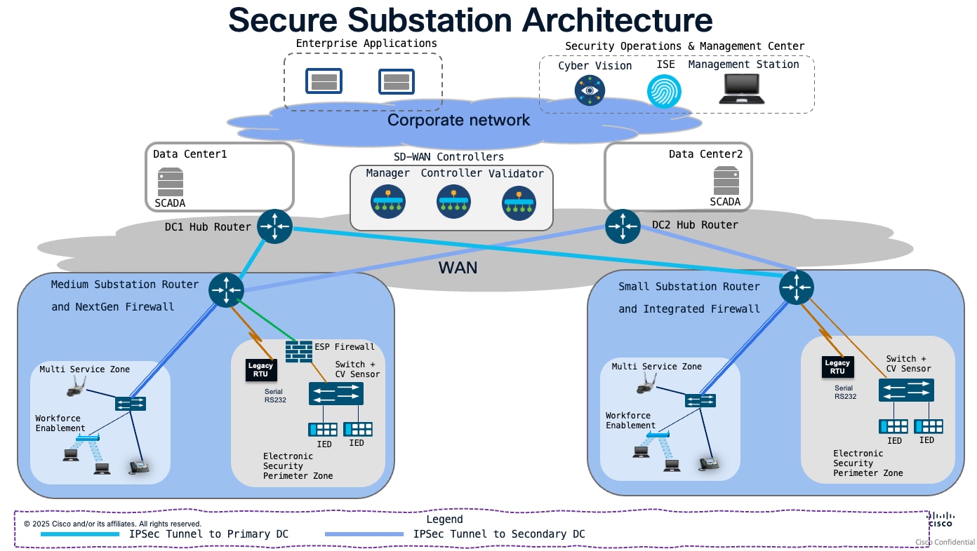
This section details the aggregation strategy for small and medium substation routers, which utilizes a Hub-and-Spoke SD-WAN topology. In this architecture, substation routers function as spokes, terminating at primary and secondary DC hub routers located in geographically redundant data centers (DC1 and DC2). This design ensures high availability and resilient connectivity for all substation routers, regardless of their specific size or deployment model.
Northbound and Southbound Connectivity
In this architecture, the Data Center 1 and Data Center 2 hubs serve as the primary aggregation points for the WAN. Southbound, these data centers connect to the WAN infrastructure to aggregate spoke traffic. Northbound, they connect to the corporate network, which acts as the transport medium for extended service delivery.
The Enterprise Applications Center and the Security Operations & Management Center are also integrated into the corporate network. This connectivity allows for the extension of dedicated Service VPNs from the data center hubs to these application centers, ensuring that traffic remains logically segmented and secure across the entire transit path.
This section outlines how Service VPNs facilitate traffic segmentation and delineates the two primary termination strategies: local processing within the data centre and extension across the corporate network.
 |
WAN Edge Aggregation at Data Center routers
The secure substation architecture utilizes a robust WAN edge aggregation strategy, where substation spokes terminate at primary and secondary hub routers located in Data Center 1 (DC1) and Data Center 2 (DC2). These hub routers serve as the critical transit points for traffic between the substation environment and the corporate network.
The dual-hub deployment across geographically redundant data centers ensures high availability through automated path failover, while the centralized SD-WAN control plane guarantees consistent security and routing policy enforcement across all substation spokes.
Deploying hub routers in two geographically separate data centers (DC1 and DC2) creates a dual-homed environment for substation spokes. The tunnels from substation routers to both DC1 and DC2 hubs are typically established and remain active by default, resulting in an Active/Active state at the IPsec tunnel level. If one data center or hub router becomes unreachable, the SD-WAN fabric automatically reroutes traffic to the secondary hub.
Active/Standby behaviour can be configured through control policies or routing preferences, where one hub serves as the primary and the other as the backup; however, this is a design choice rather than the default configuration.
Policies (security, QoS, routing) are defined centrally on the vManage controller and pushed to the vSmart controllers. Because the vSmart controllers distribute the same policy sets to all hub routers, you ensure that a "SCADA" or "Management" service VPN is treated exactly the same way, regardless of which data center the traffic traverses. This eliminates the "configuration drift" common in traditional, box-by-box managed environments.
WAN Edge Scaling and Deployment Considerations
For guidance on scaling of WAN Edge routers and SD-WAN deployment best practices, for SD-WAN controller positioning, please consult the Cisco SD-WAN Design guide. This documentation assumes that SD-WAN data tunnels are already established and operational, providing the necessary foundation for service VPN communication between spokes and hubs.
To ensure strict logical isolation, the architecture employs Service VPNs (or VRFs) that terminate directly on the DC1 and DC2 hub routers. This approach maintains end-to-end segregation of traffic, ensuring that distinct functional domains—such as SCADA applications, enterprise applications, security operations, and management services—remain isolated from one another throughout the transit path.
Various services are segregated using service VPNs. Example of services include SCADA service, Physical security service, VOIP service, Security Operations & Management Service, Work Force service, and so on.
The following table outlines the mapping of functional requirements to specific Service VPNs, ensuring consistent policy enforcement across the substation environment.
Table 2. Service Segmentation
| Device/Functionality |
Service VPN (SVC) name |
| SCADA communication traffic
|
SCADA-SVC
|
| Physical security (Surveillance/Cameras)
|
PHYSEC-SVC
|
| VOIP Phone/Voice Communication |
VOIP-SVC
|
| Security Operations, Management, 802.1X/ISE |
SEC-OPS-MGMT-SVC |
| User access and workforce enablement |
WORKFORCE-SVC
|
The architecture supports two primary models for service termination, providing the flexibility to accommodate diverse application requirements:
Local Service Termination: Services are processed and terminated directly within the Data Center environment.
Extended Service Connectivity: Services are segregated at the WAN edge but extended across the corporate network
The architecture supports both local data center hosting and extended service connectivity, allowing for a hybrid approach to application placement. This allows architects to optimize traffic paths based on specific service requirements.
This model is utilized for applications that are co-located within the data center environment, ensuring minimal latency and direct injection into the service fabric.
As an example, the SCADA application resides directly within the data center. It is connected locally to the DC Hub Router, where it is mapped to the SCADA-specific Service VPN. This provides a direct, high-performance path for time-sensitive industrial control traffic.
For applications hosted outside the data centre, the architecture extends the specific Service VPNs across the corporate network. This allows for secure, segmented access while maintaining the logical separation of the traffic flows.
Security Operations & Management Applications such as Cisco ISE, Cyber Vision, and other management stations are hosted within the Security Operations & Management Center. These are accessed by extending the dedicated “Security Operations & Management Service VPN” (SEC-OPS-MGMT-SVC) across the corporate network to the hub routers.
Enterprise/IT Applications: General enterprise applications reside within the Enterprise Applications Center. These could be physical security monitoring applications, voice management applications, email & instant messaging access. These are similarly reached via a separate, dedicated Enterprise Service VPNs (like PHYSEC-SVC, VOIP-SVC, WORKFORCE-SVC) that are extended across the corporate network.
Table 3. Service segregation with connectivity model
| Device/Functionality |
Service VPN (SVC) name |
Connectivity Model |
| SCADA communication traffic
|
SCADA-SVC
|
Local Service Termination |
| Physical security (Surveillance/Cameras)
|
PHYSEC-SVC
|
Extended Service Connectivity |
| VOIP Phone/Voice Communication |
VOIP-SVC
|
Extended Service Connectivity |
| Security Operations, Management, 802.1X/ISE |
SEC-OPS-MGMT-SVC |
Extended Service Connectivity |
| User access and workforce enablement |
WORKFORCE-SVC
|
Extended Service Connectivity |
Summary of Architectural Considerations
The following points summarize the key design principles for this WAN and service integration:
Scalable Aggregation:Centralized hub routers in dual data centers provide high availability.
Logical Isolation:The use of Service VPNs ensures that sensitive SCADA, Enterprise/IT services, management and security services, and workforce traffic remain cryptographically and logically separated.
Scalability:This modular approach allows you to add new services in the future simply by defining a new Service VPN and extending it to the required destination, without impacting existing traffic flows.
Deployment Flexibility:The architecture supports both local data center hosting and extended connectivity, allowing for a hybrid approach to application placement.
Policy Consistency:Extending the Service VPN/VRF over the corporate network ensures that security policies applied at the substation edge are maintained consistently across the entire transit path to the application source.
Platform Considerations for Data Center Hub Routers:
When selecting a Data Center (DC) Hub router, the choice must be driven by the specific scale and performance requirements of the SD-WAN overlay. Key factors include SD-WAN IPsec throughput, the number of transports required at spoke, the total number of concurrent SD-WAN overlay tunnels, and the required port density.
References:
Cisco 8500 Series (PQC ready) Secure Routers Data Sheet
Cisco Catalyst 8500 Series Edge Platforms Data Sheet
Cisco Catalyst 8300 Series Edge Platforms Data Sheet
The number of overlay tunnels is determined by the TLOC configuration at both the substation router (spoke) and the Data Center router (hub). The following scenarios define the scale requirements:
Table 4. TLOC Configuration
| Router role |
Ethernet |
Cellular |
Total TLOCs |
Description |
| Substation Router (Dual Transport) |
Yes |
Yes |
2 |
1 TLOC per Ethernet WAN + 1 TLOC per Cellular WAN |
| Substation Router (Single Transport) |
Yes |
- |
1 |
1 TLOC per Ethernet WAN |
| Substation Router (Single Transport) |
- |
Yes |
1 |
1 TLOC per Cellular WAN |
| Data Center Hub Router |
Yes |
- |
1* |
1 TLOC per Hub Router (1x Ethernet WAN interface) |
The TLOC counts above assume that all Spoke transport types (Ethernet and Cellular) can reach the Hub router’s Ethernet interface.
NAT requirements for Mixed Transport
In deployments where the Hub router’s Ethernet interface resides on a private network, the Spoke’s Ethernet transport can establish tunnels via direct private routing. However, if the Cellular transport (Public Internet) lacks direct reachability to the Hub’s private Ethernet interface, NAT/Port Forwarding must be deployed at the Data Center’s public internet boundary. This configuration maps the public-facing NAT IP to the Hub’s private Ethernet interface, ensuring that Cellular-originated tunnel traffic is correctly translated and forwarded to the Hub.
The total number of IPsec tunnels per substation is calculated based on the connectivity to two geographically redundant hubs (DC1 and DC2):
Table 5. Substation Router transport type, TLOCs per spoke, TLOCs per Hub
| Substation Router transport type |
TLOCs per spoke |
TLOCs per Hub |
Total Tunnels (DC1 + DC2) |
| Dual-Transport |
2 |
1 |
4 Tunnels (2 Tunnels per DC) |
| Single-Transport |
1 |
1 |
2 Tunnels (1 Tunnel per DC) |
Formula: Total Tunnels = (Spoke TLOCs) × (Hub TLOCs per DC) × (Number of DCs)
Note: Total tunnel count is a critical factor for OMP scale and control plane stability. Ensure the selected router models for Hub router(Catalyst 8300/8500) are sized to support the aggregate tunnel count across all sites.
Based on the Cisco Catalyst 8300 limit of *6,000 tunnels:
Table 6. Substation Router transport type, TLOCs per spoke, TLOCs per hub
| Substation Router transport type |
TLOCs per spoke |
TLOCs per Hub |
Number of substations that can be aggregated |
| Dual-Transport |
2 |
1 |
6000/2 = 3000 substations |
| Single-Transport |
1 |
1 |
6000/1 = 6000 substations |
Based on the Cisco Catalyst 8500 limit of 8,000-*10,000 tunnels:
Table 7. Substation Router transport type, TLOCs per spoke, TLOCs per hub
| Substation Router transport type |
TLOCs per spoke |
TLOCs per Hub |
Number of substations that can be aggregated |
| Dual-Transport |
2 |
1 |
10000/2 = 5000 substations |
| Single-Transport |
1 |
1 |
10000/1 = 10000 substations |
*6000/*10000 tunnels” please refer to data sheet for latest numbers. The example mentioned above is for reference purpose only
Data Centre Hub Router - Throughput Sizing and Capacity Planning
To maintain optimal network performance and low latency, the Data Center Hub router must be sized to accommodate the aggregate volume of traffic from all remote substations.
The required hub capacity is determined by the following formula:
Total Aggregate Traffic = (Average Throughput per Substation) × (Total Number of Substations)
Platform Selection Recommendation
It is recommended to select a Hub router with an SD-WAN IPsec (IMIX) throughput rating that meets or exceeds the calculated aggregate traffic. Designers should refer to the platform’s data sheet and account for a 20–30% headroom to accommodate future growth, bursty traffic patterns, and the overhead of additional services (such as Firewall or DPI).
Standard Performance: For aggregate throughput requirements below 7.6 Gbps (IPsec IMIX), the Cisco Catalyst 8300 Seriesis recommended
High Performance: For aggregate throughput requirements exceeding 7.8 Gbps (IPsec IMIX), the Cisco Catalyst 8500 Series (e.g., C8500-12X) is required
PQC-Ready High Performance:For high-performance deployments requiring Post-Quantum Cryptography (PQC) readiness, the Cisco Catalyst 8500 Series Secure Routers(e.g., C8550-G2) are the required platforms.
Platform Selection Scenarios (Scale vs. Throughput)
The following examples illustrate how to select a platform based on the number of substations and their transport configurations, assuming a dual-homed environment (DC1 and DC2) where each hub has one WAN TLOC.
Table 8. Substation Router transport type, Tunnels per Hub, Max Substations (Cat 8300)
| Substation Router transport type |
Tunnels per Hub |
Max Substations (Cat 8300) |
Max Substations (Cat 8500) |
| Single Transport (Cellular or Ethernet) |
1 |
Up to 6,000 |
Up to 10,000
|
| Dual Transport (Cellular and Ethernet) |
2 |
Up to 3,000
|
Up to 5,000 |
Aggregate throughput to be considered = (Average Throughput per Medium substation * number of medium substations) + (Average Throughput per Small substation * number of small substations)
Platform Selection - Scenario-Based Examples
Combine this decision along with the throughput-based platform selection recommendation mentioned earlier.
Example 1: A deployment of 6,000 substations using Single Transport (Cellular only).
Total Tunnels per Hub: 6,000.
Choice: Cisco Catalyst 8300 Series (meeting the maximum scale limit).
Example 2: A deployment of 3,000 substations using Dual Transport (Cellular + Ethernet).
Total Tunnels per Hub: 6,000.
Choice: Cisco Catalyst 8300 Series (meeting the maximum scale limit).
For the high-scale scenarios listed below, the Cisco Catalyst 8500 Series is required, with the Secure variant strongly recommended to ensure enhanced security, PQC readiness and future-proof capabilities.
Example 3: A deployment of more than 3,000 substations using Dual Transport.
Total Tunnels per Hub: > 6,000.
Choice: Required for higher tunnel density
Example 4: A deployment of more than 6,000 substations using Single Transport.
Total Tunnels per Hub: > 6,000.
Choice: Required for higher tunnel density
Example 5: A deployment of 5,000 substations using Dual Transport.
Total Tunnels per Hub: 10,000.
Choice: Required for high-scale headend aggregation
Example 6: A deployment of 10,000 substations using Single Transport.
Total Tunnels per Hub: 10,000.
Choice: Required for high-scale headend aggregation
Headend Redundancy and Traffic Steering Models
In Cisco SD-WAN, the distinction between these architectures is primarily driven by TLOC (Transport Locator) Preference and OMP (Overlay Management Protocol) Path Selection.
Active/Standby Headend Architecture (Deterministic Path)
In an Active/Standby design, control plane can be influenced in such a way that the spokes prefer one hub over the other. This is achieved using TLOC Preference or OMP Cost.
Active/Standby architecture is best for Architectures where traffic predictability is paramount, or where security policies require all traffic to pass through a specific primary inspection point (e.g., a specific firewall cluster).
The Primary hub (DC1) is configured to advertise routes with a higher TLOC preference (or lower OMP cost) than the secondary hub (DC2). The substation routers will install the DC1 path into their Forwarding Information Base (FIB) and keep the DC2 path in the routing table as a backup.
If the primary DC1 hub becomes unreachable (TLOC disappears), the SD-WAN fabric automatically promotes the DC2 path to the active state. Because the tunnels to DC2 are already established (pre-warmed), the failover is rapid.
Provides a highly deterministic traffic flow. Troubleshooting is simplified because the path taken by packets is consistent and predictable.
Active/Active Headend Architecture (Load-Sharing)
In an Active/Active headend architecture, substation spokes maintain concurrent, active IPsec tunnels to both DC1 and DC2 hub routers. Traffic is load-balanced across both paths, effectively utilizing the bandwidth of both data centres simultaneously. By default, the Cisco SD-WAN control plane advertises identical OMP (Overlay Management Protocol) route metrics from both hubs, enabling the spokes to perform Equal-Cost Multi-Path (ECMP) load sharing.
Active/Active architecture is best for environments requiring maximum bandwidth utilization. This design provides high availability and ensures that both primary and secondary data centers are providing value.
ECMP & OMP: Spokes receive identical routing information from both DCs and load-balance traffic across both paths at the flow level. Both hubs advertise the same service routes (or subnets) with the same OMP cost. The spokes see two TLOCs for the same destination and utilize both for traffic forwarding.
● Application-Aware Routing (AAR): Policies are applied to steer specific applications over the optimal path. For example, SCADA traffic can be pinned to the path with the lowest latency, while management traffic utilizes the alternative path.
● BFD-Driven Resiliency: BFD runs continuously on all tunnels. If a tunnel to DC1 fails, BFD detects the loss, and the spoke immediately redirects all traffic to the active DC2 tunnel with sub-second convergence.
● Optimized Resource Utilization: Maximizes the return on investment for data center infrastructure by ensuring both hubs are actively processing traffic.
● Failover: Because tunnels are already established and actively passing traffic, the SD-WAN fabric can reroute traffic instantly if one path fails, minimizing disruption to sensitive SCADA applications.
● Dynamic Load Balancing: The SD-WAN control plane can dynamically distribute traffic flows based on real-time path performance metrics (e.g., latency, jitter, and loss).
● Consideration: Requires careful monitoring of path symmetry. If your firewalls or security appliances are stateful, ensure that return traffic is handled correctly across the dual-hub environment.
Active/Active vs Active/Standby - Architectural Comparison Summary
Table 9. Feature, Active/Active (Load-Sharing), Active/Standby (Deterministic)
| Feature |
Active/Active (Load-Sharing) |
Active/Standby (Deterministic) |
| Primary Mechanism |
Equal OMP Cost / ECMP |
TLOC Preference / OMP Cost |
| Bandwidth Usage |
Aggregated across both hubs |
Utilizes primary hub only |
| Traffic Flow |
Dynamic / Load-balanced |
Deterministic / Predictable |
| Complexity |
Moderate (Requires symmetry checks) |
Low (Easier to audit/troubleshoot)
|
| Failover |
Immediate (Path-based) |
Immediate (Control plane update) |
Chapter 6 Medium Substation Design
This chapter describes the medium transmission substation design for the Secure Substation design guide. It applies the security reference architecture and security design principles from earlier chapters to a validated medium substation profile using the Cisco IR8340 as the substation WAN edge router and Cisco Industrial Ethernet switching for the station LAN.
The medium substation profile and solution-wide requirements are defined in earlier chapters. This chapter applies those requirements to the site-level design for a medium transmission substation using a Cisco IR8340 WAN edge router, Cisco Industrial Ethernet switching, service VPN segmentation, and integrated or discrete firewall enforcement.
The validated design supports the following use cases:
● SCADA monitoring and control between the substation and OT data center.
● Station bus communication for substation automation and monitoring.
● PMU or synchrophasor traffic where deployed.
● Physical security services such as cameras, badge readers, alarms, and associated monitoring systems.
● Controlled workforce enablement for field technicians, protection engineers, and approved vendors.
● Management access for routers, switches, firewall functions, Cyber Vision, identity services, logging, and software lifecycle operations.
● Legacy serial integration using RS-232, raw socket transport, or serial pseudowire where legacy devices remain in service.
Validated Medium Substation Topology
The validated medium topology uses a single Cisco IR8340 as the substation WAN edge router. The IR8340 connects the medium substation to the utility WAN and aggregates services from the station LAN, physical security systems, management services, workforce access services, PMU devices, and legacy serial devices.
The station LAN uses a Cisco IE9320 Industrial Ethernet switch to connect IEDs, RTUs, gateways, protection relays, PMU devices, engineering systems, management endpoints, physical security devices, and Cyber Vision sensor functions.
The OT data center provides SCADA and control center applications. Primary and secondary OT data center WAN edge hubs in DC1 and DC2 terminate substation WAN connectivity. The SOC consumes Cyber Vision data, firewall events, authentication events, IDS/IPS events, and other security telemetry. The NOC operates Catalyst WAN Manager and related WAN lifecycle functions.
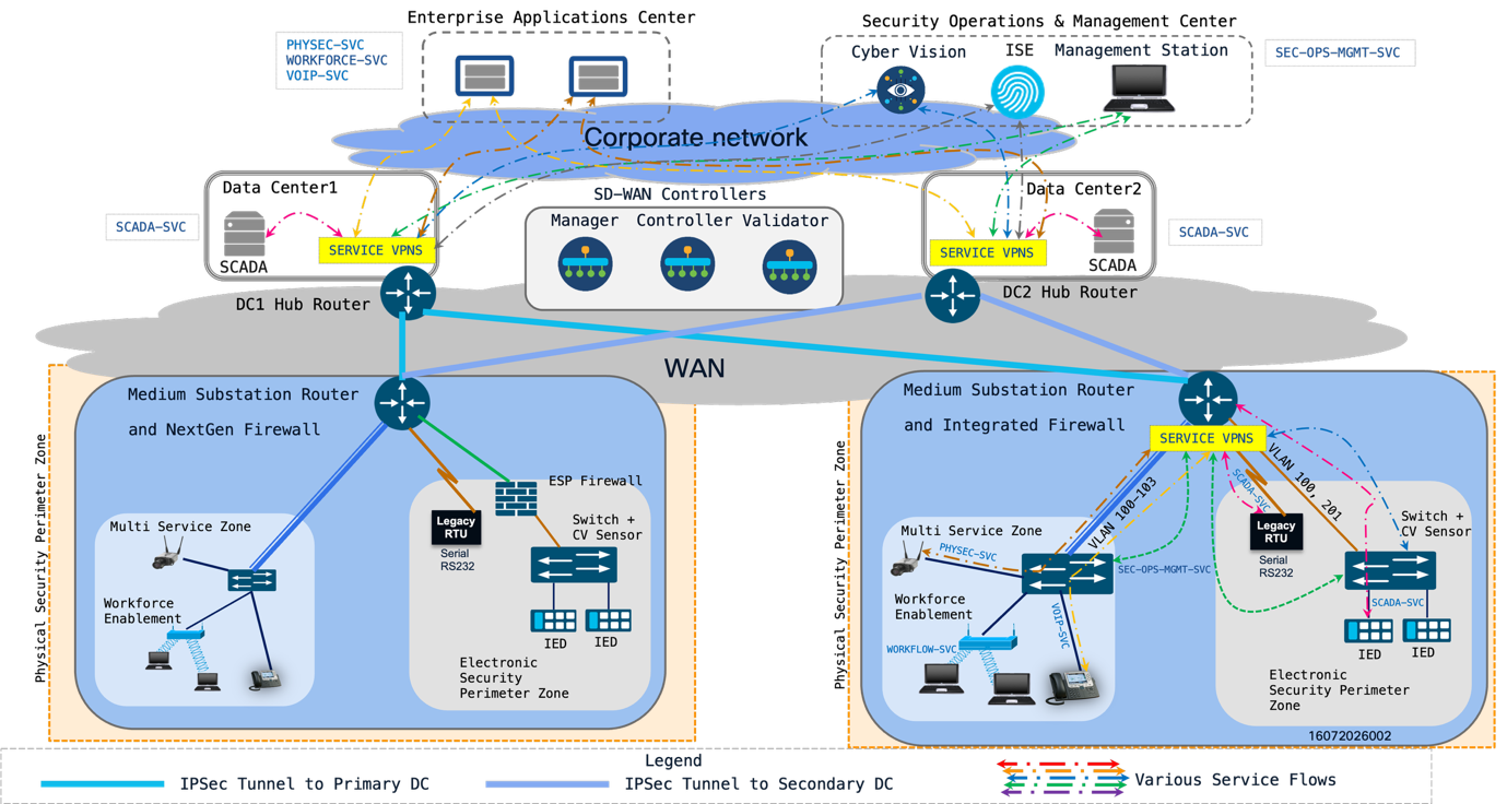 |
The topology supports two firewall placement options:
Design Option 1: Integrated Firewall - The IR8340 provides WAN edge routing, service VPN/VRF termination, segmentation, and firewall enforcement on the same platform.
Design Option 2: Discrete Firewall - The IR8340 provides WAN edge routing and service aggregation, while a separate firewall enforces policy at the ESP boundary or between major service segments.
Both options use the same logical service-separation model. The selection depends on inspection requirements, operational ownership, footprint, power, availability requirements, policy lifecycle, and utility security standards.
Design Option 1: Integrated Firewall
In the integrated firewall option, the IR8340 provides WAN edge routing, service VPN/VRF termination, station LAN handoff, segmentation, and firewall enforcement on the same platform. This model is useful when the utility wants a compact medium substation design with fewer devices, simplified cabling, lower power consumption, and centralized lifecycle operations.
The IR8340 is the substation WAN edge router and the ESP boundary policy enforcement point. It is mapped as the Electronic Access Point for routable connectivity into and out of the ESP and as an Electronic Access Control or Monitoring System because it provides firewall enforcement, access control, logging, and monitoring for ESP-bound traffic. Interactive Remote Access is handled through the approved workforce access service path and associated remote access control components.
Integrated Firewall Implementation
The integrated firewall option is implemented by using the IR8340 as the WAN edge router, service VPN/VRF termination point, and ESP boundary enforcement point. The design uses routed interfaces or subinterfaces, service VPNs implemented as VRFs, firewall zones, and explicit inter-zone policy to control traffic between the WAN, station LAN, protected OT assets, management services, physical security services, workforce access services, and legacy serial services.
Throughput is validated by building a traffic profile for the medium substation and comparing it against the validated IR8340 platform and software release. The profile should include baseline SCADA traffic, PMU traffic where deployed, Cyber Vision telemetry, physical security traffic, management traffic, logging, software updates, and WAN encryption overhead. PMU and video traffic should be accounted for separately because either service can materially change the WAN and inspection load. The final design should reserve capacity for burst traffic and future service growth.
The ESP boundary is implemented at the IR8340 policy enforcement point. The interfaces, subinterfaces, service VPNs/VRFs, and firewall zones that carry routable traffic into or out of the ESP are documented as the EAP mapping for the integrated firewall design. This mapping also identifies the IR8340 as EACMS because the platform enforces firewall policy, logs access events, and monitors ESP-bound traffic.
Firewall and threat inspection placement is identified by service path. Zone-Based Firewall provides the baseline segmentation between IR8340 zones, while NGFW, IDS/IPS, and SCADA protocol inspection are applied only to the traffic paths selected in the validated design. Detailed firewall policy, signature selection, DNP3 inspection behavior, and custom Snort rule design are covered in the Firewall and Threat Inspection Design chapter.
Management traffic is carried in a separate management or security operations service VPN/VRF. Device administration, AAA, ISE, logging, Cyber Vision, backup, and software lifecycle traffic should not share the same unrestricted path as SCADA control traffic. Access from the NOC, SOC, and approved management systems is explicitly permitted; all other management access is denied by default.
Inter-service communication is controlled through least-privilege policy. Broad permits between service VPNs/VRFs are avoided. Required flows are defined by source, destination, protocol, port, and direction. Route leaking between service VPNs/VRFs is used only where required by the design and is paired with firewall policy so that routing reachability does not imply application access.
Security events are forwarded to the SOC or approved security monitoring platform. The integrated firewall design should forward firewall logs, IDS/IPS events where used, authentication events, system events, and relevant WAN or tunnel events. Time synchronization should be consistent across the IR8340, switches, Cyber Vision, identity services, and logging systems so that events can be correlated during operations and incident response.
Design Option 2: Discrete Firewall
In the discrete firewall option, the IR8340 remains the substation WAN edge router and service aggregation point. A separate firewall is placed at the ESP boundary or between major substation service segments to provide dedicated policy enforcement.
This option is useful when the utility requires dedicated firewall administration, expanded NGFW inspection, independent policy lifecycle, separate SOC ownership, or a stronger separation between routing and security enforcement functions.
The discrete firewall option can provide:
IR8340-based WAN edge routing and service aggregation.
Dedicated firewall placement for ESP boundary enforcement.
Separation between WAN routing and firewall inspection functions.
Expanded NGFW policy options where required by utility policy.
Independent firewall software lifecycle and rule-management process.
Clearer operational separation between NOC-managed WAN functions and SOC-managed security policy.
In the discrete firewall option, the separate firewall is the ESP boundary policy enforcement point and is mapped as the Electronic Access Point and Electronic Access Control or Monitoring System. The IR8340 remains the substation WAN edge router and service aggregation point. Interactive Remote Access is handled through the approved workforce access service path and associated remote access control components.
Discrete Firewall Design Considerations
The discrete firewall option adds hardware, cabling, power, and operational handoff points. It can be selected when the utility requires a dedicated security enforcement platform between the WAN edge and the protected station LAN services.
In this option, the firewall placement should make the ESP boundary clear and enforceable. Traffic between the IR8340, station LAN, and protected service segments should pass through the discrete firewall where policy enforcement is required, and the topology should avoid alternate paths that bypass the firewall.
Routing between the IR8340, firewall, station LAN, and service segments should align with the service VPN/VRF and VLAN design. Firewall policy, route exchange, interface zoning, and log forwarding to the SOC should be treated as one coordinated design so that segmentation, inspection, and monitoring remain consistent across the WAN edge and local LAN boundary.
Where the firewall platform supports fail-open, fail-close, or bypass behavior, the selected mode should match the utility's operational policy for the protected service. The behavior should be applied deliberately because the selected mode affects both ESP boundary enforcement and service continuity.
The single IR8340 edge design consolidates WAN connectivity, routing, service VPN/VRF termination, segmentation, firewall integration, and legacy serial support into one ruggedized substation platform.
The IR8340 provides the following functions in the medium substation design:
● WAN edge connectivity to primary and secondary OT data center WAN edge hubs.
● Service aggregation for SCADA, physical security, workforce, management, security operations, PMU, voice, enterprise, and legacy serial traffic.
● Service VPN/VRF separation for traffic classes with different trust levels.
● VLAN termination or routed handoff from the station LAN.
● Zone-Based Firewall and integrated security functions where used.
● IDS or IPS functions where supported by the platform and validated software release.
● Serial integration using raw socket or serial pseudowire options.
● Catalyst WAN Manager-based lifecycle operation where centralized management is used.
The single-edge model reduces site footprint and simplifies deployment. The tradeoff is that WAN connectivity, routing, segmentation, and integrated firewall functions share a common platform. Failure behavior, restart behavior, management-plane loss, and WAN failover should be documented and validated before production deployment.
WAN Aggregation for the Medium Substation
The medium substation IR8340 operates as a WAN spoke and follows the WAN edge aggregation recommendations defined in Chapter 5, WAN Edge Aggregation and Service Segmentation Architecture. The IR8340 is aggregated by OT data center WAN edge hub routers located in geographically redundant data centers, DC1 and DC2.
Chapter 5 defines the common aggregation model, including hub-and-spoke connectivity, active/active and active/standby headend steering options, TLOC and tunnel-count scaling, hub platform sizing, northbound and southbound connectivity, local service termination, and extended service connectivity. This chapter does not repeat those details.
For the medium substation, the site design identifies the following IR8340-specific values:
● WAN transport type, such as fiber, MPLS/SR, or Cellular/LTE.
● Single-transport or dual-transport spoke model.
● DC1 and DC2 hub routers used for aggregation.
● Active/active or active/standby headend steering model.
● Transport Locator count for the medium substation spoke.
● IPsec tunnel requirements and expected tunnel count.
● Service VPN/VRF mapping at the substation IR8340 and OT data center hubs.
● Local service termination and extended service connectivity requirements.
Northbound and Southbound Connectivity
The medium substation design uses the northbound and southbound connectivity model defined in Chapter 5.
This chapter identifies only the medium-substation service placement: which services terminate locally in the OT data center and which services extend northbound to approved SOC, NOC, security operations, enterprise, or corporate application environments.
Service VPN Architecture for Medium Substation
Service VPNs provide overlay service segmentation. On the IR8340 and OT data center WAN edge hubs, these service VPNs are implemented as VRFs or equivalent routing instances. This chapter uses service VPN/VRF to describe the service segment carried across the WAN and enforced on the router.
The medium substation uses the service segmentation recommendations from Chapter 5. The service VPN/VRF mapping below applies that model to the medium substation design and adds medium-substation-specific services, such as PMU and legacy serial transport where deployed.
The following table provides a baseline service mapping for the medium substation design.
Table 10. Functions and Service Mapping
| Device or Function |
Service VPN Name |
| SCADA communication traffic |
SCADA-SVC |
| Physical security, surveillance, cameras, alarms |
PHYSEC-SVC |
| Voice and phone services |
VOIP-SVC |
| Security operations, management, Cyber Vision, ISE, logging |
SEC-OPS-MGMT-SVC |
| Workforce enablement and approved user access |
WORKFORCE-SVC |
| PMU or synchrophasor traffic where deployed |
PMU-SVC |
| Legacy serial traffic mapped to IP transport |
mapped to SCADA-SVC |
The service names shown in the table are illustrative. Utilities may use a different naming convention, but the design should preserve the Chapter 5 service segmentation intent and document the mapping between service VPNs/VRFs, VLANs, firewall zones, and application destinations.
Service VPN/VRF to Zone-Based Firewall Zone Mapping
In the integrated firewall option, service VPNs provide routing and overlay segmentation, while Zone-Based Firewall zones define the local policy enforcement boundary on the IR8340. A service VPN is implemented as a VRF or routing instance, and the IR8340 interfaces or subinterfaces associated with that service are assigned to the appropriate firewall zone. Firewall policy is applied when traffic crosses between zones.
The recommended design is to align ZBFW zones with trust and policy boundaries. A service VPN/VRF should map to a dedicated firewall zone when the service has a distinct trust level, destination set, inspection requirement, or operational behaviour. Multiple VLANs or interfaces can share a firewall zone only when they belong to the same service boundary and require the same policy treatment. Services with different trust levels, such as SCADA, management, workforce access, physical security, and enterprise support traffic, should not be combined in the same firewall zone.
Table 11. Zones, Functions and Service Mapping
| Service |
Service VPN/VRF |
Typical ZBFW Zone |
Design Intent |
| SCADA and station bus traffic |
SCADA-SVC |
ESP-ZONE |
Protect routable communication to OT assets inside the ESP. |
| PMU traffic |
PMU-SVC or SCADA-SVC |
ESP-ZONE or PMU-ZONE |
Keep PMU flows aligned to the SCADA service model or separate them when bandwidth, policy, or destination requirements differ. |
| Physical security traffic |
PHYSEC-SVC |
PHYSEC-ZONE |
Separate camera, badge, and physical security services from SCADA control traffic. |
| Workforce access traffic |
WORKFORCE-SVC |
WORKFORCE-ZONE |
Control field engineering, remote desktop, and approved workforce access paths. |
| Security operations and management traffic |
SEC-OPS-MGMT-SVC |
MGMT-ZONE |
Carry device administration, ISE, Cyber Vision, logging, backup, and software lifecycle traffic separately from control traffic. |
| Legacy serial traffic mapped to IP transport |
LEGACY-SERIAL-SVC or SCADA-SVC |
ESP-ZONE |
Keep raw socket or serial pseudowire traffic aligned to the protected OT service it supports. |
The zone assignment should reflect the policy intent for the service. SCADA, station bus, and legacy serial traffic remain aligned to the protected OT service. Physical security, workforce access, and management or security operations traffic are separated from SCADA control traffic because they have different trust levels, destinations, and operational behavior.
For the discrete firewall option, the same service VPN/VRF intent is preserved, but firewall zone enforcement is provided by the discrete firewall rather than by ZBFW on the IR8340. The IR8340 remains the WAN edge and service aggregation point, and the firewall interfaces or subinterfaces provide the policy boundaries for traffic entering or leaving protected service segments.
The medium substation LAN uses a Cisco IE9320 Industrial Ethernet switch to provide ruggedized station LAN connectivity. The switch connects station bus devices, IEDs, RTUs, gateways, PMU devices, engineering workstations, physical security endpoints, management interfaces, and Cyber Vision sensor functions.
The LAN design should separate endpoints based on function, criticality, and required communication paths. VLANs provide local Layer 2 separation. Routed interfaces, service VPNs/VRFs, and firewall policy zones provide higher-level separation and policy enforcement.
The LAN design should avoid a flat station network. Endpoints should be assigned to VLANs or routed segments according to their function and communication requirements.
Key design considerations include:
● Keep SCADA and station bus communication paths tightly scoped.
● Separate physical security traffic from SCADA control traffic.
● Separate management access from control traffic.
● Use trunking only where required and limit allowed VLANs.
● Apply storm control and multicast controls where required by the traffic profile.
● Avoid unmanaged switch placement inside protected areas.
● Document Cyber Vision monitoring points and expected east-west visibility.
● Validate spanning tree or ring behavior if redundant Layer 2 paths are used.
Firewall and Threat Inspection Placement
Firewall and threat inspection design is covered in a separate chapter. In this medium substation chapter, the design identifies where inspection functions are placed in the validated topology.
In the integrated firewall option, the IR8340 is the ESP boundary enforcement point. ZBFW, NGFW, UTD IDS/IPS, and SCADA protocol inspection are applied on the IR8340 where supported by the validated platform and software release. In the discrete firewall option, the separate firewall is the primary ESP boundary inspection point, while the IR8340 remains the WAN edge router and service aggregation point.
The detailed policy definition, service-path selection, IDS or IPS mode selection, DNP3 inspection behavior, custom Snort rule logic, signature update model, and blocking criteria are defined in the Firewall and Threat Inspection Design chapter.
Raw Socket Transport for Legacy Serial Devices
Medium substations may include legacy serial RTUs, meters, protection devices, or automation systems that must remain operational during modernization. The IR8340 supports serial integration options that allow legacy serial traffic to be carried across the IP architecture.
Raw socket transport is a design option for carrying serial traffic as IP flows. VRF-aware raw socket options allow serial traffic to remain aligned with the same segmentation model used for Ethernet services. For example, serial SCADA traffic can be mapped to the SCADA-SVC service VPN/VRF while management traffic remains in a separate management service VPN/VRF.
In this option, a legacy RTU or serial device can be associated with a specific control center destination, such as a SCADA front-end processor, headend serial gateway, or SCADA application that can consume raw socket traffic directly. The IR8340 provides the local RS-232 serial attachment and carries the serial stream as an IP flow using the selected service VPN/VRF, source interface, destination address, and TCP or UDP port.
A TCP-based raw socket session can be used when the application requires a connection-oriented client/server model and benefits from TCP session retry behavior. A UDP-based raw socket session can be used when the application expects peer-to-peer transport and the utility application handles loss or retry behavior. Packetization can be tuned to the serial protocol and application behavior, using criteria such as packet length, delimiter character, or timeout so that the IP flow preserves the expected serial exchange pattern.
Where redundant serial or headend connectivity is required, the RTU, serial interface, service VPN/VRF, and primary or secondary control center endpoint should be mapped consistently. This allows operational teams to troubleshoot the serial circuit, raw socket session, WAN path, and SCADA application endpoint as one service path rather than as unrelated components.
Serial pseudowire is another design option where the utility-owned MPLS/SR service requires circuit-like transport for legacy serial traffic. In this model, the IR8340 at the substation and the control center provider edge can terminate the pseudowire, with either serial-to-serial or serial-to-Ethernet interworking toward the SCADA front-end processor. Raw socket is generally the simpler option when the control center application or redirector can consume serial traffic over IP without preserving a Layer 2 circuit.For more details on Raw Socket, refer to Substation Automation - The New Digital Substation.
Network Access Control for LAN-Side Devices
Network Access Control provides device admission control for LAN-side devices. In medium substations, endpoint diversity requires support for both 802.1X and MAC Authentication Bypass.
802.1X is appropriate for endpoints that support supplicant-based authentication, such as engineering workstations or managed systems. MAB is used for devices that cannot support 802.1X, such as legacy IEDs, RTUs, cameras, badge readers, or embedded controllers.
An 802.1X-based access model can be used for managed endpoints where supplicant configuration, certificate handling, and user or device authentication are operationally supportable. A MAB-based access model can be used for fixed-function OT devices that cannot run a supplicant. Cisco ISE, or the approved identity platform, can profile these endpoints and return an authorization result that places the device into the appropriate VLAN, applies an ACL, or assigns the endpoint to the required service segment.
Unknown or unauthorized endpoints can be handled with a restricted authorization result, quarantine segment, or denied access based on the utility policy. This model allows field replacement workflows to support approved device swaps while still preventing uncontrolled endpoint attachment to the station LAN.
NAC should be introduced carefully in medium substations. Monitor mode or low-impact mode can be used before enforcement so the utility can validate the inventory, confirm expected 802.1X and MAB behavior, and review authentication events without disrupting operational devices. Authentication success, failure, profiling, and authorization events should be forwarded to the SOC or approved monitoring platform.
Cyber Vision Sensor Placement and East-West Visibility
Cisco Cyber Vision provides asset visibility, protocol awareness, baseline creation, and anomaly detection inside the medium substation LAN. The IE9320-based station LAN provides the monitoring point for observing east-west traffic between station LAN endpoints.
Cyber Vision placement should provide visibility into:
● SCADA and station bus communication patterns.
● IED, RTU, gateway, and PMU communication relationships.
● Physical security and multiservice traffic where included in monitoring scope.
● Baseline behavior for known assets, protocols, and communication relationships.
● Anomaly detection for deviations from established traffic and asset behavior.
● Unexpected or unauthorized device communication.
● Protocol behavior that supports incident investigation.
Cyber Vision communications should be mapped to the security operations and management service model and forwarded to the appropriate SOC or security center systems. The sensor communication path should be separated from SCADA control traffic and documented as part of the design.
Traffic Profile and Scale Considerations
Medium transmission substations typically have larger telemetry, control, and monitoring requirements than small transmission substations. Scale planning should account for the full mix of SCADA, PMU, Cyber Vision, physical security, workforce, management, logging, software update, voice, and legacy serial traffic.
The baseline planning profile is:
Typical point count: 500-1,500 points.
Average throughput without PMUs: 0.5-2 Mbps.
Additional PMU throughput: approximately 5-10 Mbps per PMU.
Typical WAN provisioning: 10-50 Mbps using fiber, MPLS/SR, or Cellular/LTE, based on site availability and service requirements.
Common protocols: IEC 61850 MMS, DNP3, ICCP, Modbus TCP, IEEE C37.118, HTTPS, SCP, SSH, and serial traffic.
Sizing should include encryption overhead, firewall inspection overhead, event bursts, PMU reporting rates, video or physical security traffic, Cyber Vision telemetry, and software update behavior. PMU traffic should be planned independently from baseline SCADA traffic because a single PMU can materially change the WAN bandwidth profile.
For the hub aggregation design, medium substation bandwidth should also be included in the aggregate OT data center hub capacity calculation. The hub capacity requirement is based on average or engineered throughput per substation multiplied by the number of substations, with additional headroom for burst traffic, encryption overhead, security inspection, and future service growth.
Medium Substation Design Summary
The medium substation design provides a repeatable architecture for securing transmission substations with higher point counts, broader service separation needs, and larger WAN profiles than small substations. The Cisco IR8340 acts as the substation WAN edge router and supports WAN connectivity, DC1/DC2 aggregation, service VPN/VRF separation, integrated or discrete firewall models, UTD IDS/IPS, legacy serial integration, and Catalyst WAN Manager-based lifecycle operation where centralized management is used.
The design uses a Cisco IE9320 Industrial Ethernet switch for LAN-side connectivity and Cyber Vision visibility. It supports SCADA, PMU, physical security, workforce access, management, security operations, voice, enterprise, and legacy serial traffic through a structured model based on NERC CIP boundary constructs, service segments, and service VPNs implemented as VRFs.
Chapter 7 Small Substation Design
The Small Substation design is tailored for smaller distribution substations and Distribution Automation (DA) field sites. Typically accommodating a minimal footprint of devices (usually fewer than 5, and rarely exceeding 10), this architecture provides robust, secure, and highly available connectivity.
Central to this design is the Cisco Catalyst IR1101 Rugged Series Router, designated throughout this guide as the “small substation router”. Acting as the WAN edge and security boundary device, it facilitates secure southbound access for critical operational technology (IEDs and RTUs) located in Electronic Security Perimeter (ESP Zone).
The substation router also provides connectivity to other multi service applications (physical security, VoIP, and workforce access). Simultaneously, the small substation router enforces secure northbound communication by encrypting all traffic destined for the Data Center Hub routers within IPsec tunnels over the WAN.
The architecture is divided into distinct northbound (WAN) and southbound (LAN) connectivity models, managed centrally via Cisco SD-WAN to simplify operations and ensure consistent policy enforcement.
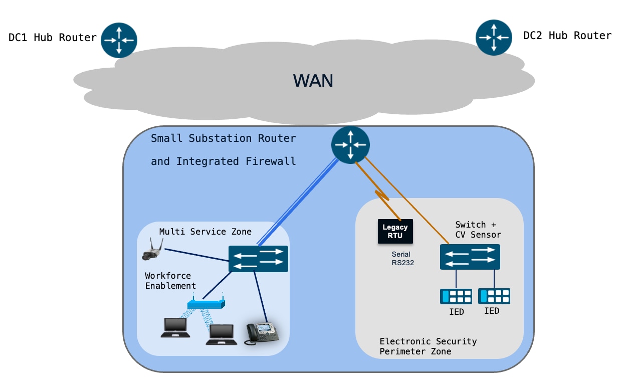 |
The architecture is built around a single Cisco IR1101 acting as the small substation router (secure WAN edge gateway), supported by two Industrial Ethernet switches for LAN connectivity.
Table 12. Component of a small substation design
| Component |
Functional Role |
| Cisco IR1101 (Small Substation Router) |
Acts as Secure WAN edge gateway, providing routing, ZBFW, WAN encryption (IPsec), SD-WAN edge functions, and serial device connectivity |
| Cisco IE3500 |
Deployed within the ESP Zone to facilitate secure connectivity for critical IEDs/utility controller devices. Cyber Vision sensor is installed on this switch. |
| Cyber Vision Sensor |
Cyber Vision sensor is installed Cisco IE3500 switch, To Automatically inventory what's connected to your industrial network. Strengthen your OT security posture. |
| Cisco IE3100 |
Deployed within the Multi-Service Zone to aggregate non-critical traffic, including physical security, VoIP, and workforce access. |
| Legacy serial RTUs |
Connected directly into the small substation router to support serial-to-IP transport.
|
| IEDs and Utility controller devices |
Connected to the network via the IE3500 ESP switch. |
| Physical Cameras, VOIP, User laptops |
Connected to the network via the IE3100 Multi-Service Zone switch. |
| 4-port expansion module (IRM-1100-4S8I) |
Optional modular hardware used to increase LAN port density; one port can be optionally provisioned as an additional WAN interface. |
Northbound (WAN) Connectivity
The small substation router connects to the WAN utilizing either single or dual transport links (e.g., Cellular and Ethernet). Functioning as an SD-WAN spoke, it establishes secure IPsec tunnels to the headend Hub routers located in DC1 and DC2, supporting both Active/Active and Active/Standby routing designs.
To accommodate scalable connectivity requirements, an optional 4-port expansion module (IRM-1100-4S8I) can be integrated. This module not only expands the number of available LAN interfaces but also provides the flexibility to provision one of its ports specifically for WAN transport.
Southbound (LAN) Connectivity
The IR1101 provides downstream connectivity to two primary zones:
● Electronic Security Perimeter (ESP) Zone: Utilizes the Cisco Catalyst IE3500 switch to enable secure connectivity to critical IEDs and protection assets. The IR1101 acts as the ESP boundary device, hosting the Electronic Access Point (EAP).
● Multi-Service Zone: Utilizes the Cisco Catalyst IE3100 switch for non-critical services, including physical security cameras, workforce mobility, and VoIP.
Switch Management
Switch management connectivity resides in both the ESP Zone and the Multi Service Zone, delivered inline over the dedicated management VLAN.
Legacy Serial Devices:The router directly connects to legacy serial RTUs. Raw-socket connections are established within a dedicated service VPN, enabling serial SCADA traffic to be transported securely over IP to the SCADA FEPs in both the data centers.
Network Segmentation and Service VPNs
Services are delivered using Service VPNs (VRFs). To maintain strict isolation between critical and non-critical traffic, services are segregated using SD-WAN Service VPNs on the small substation router, mirroring the service VPN architecture at the DC Hubs. The services located behind the hub-side service VPNs can be seamlessly reached by connecting to the corresponding service VPN on the small substation router.
The Layer 2 connection between the IE switches and the small substation router is configured in trunk mode, carrying the subset of VLANs required for the configured services. Management access to the IE3100 and IE3500 switches is provided inline using a dedicated management VLAN (e.g., VLAN 100).
At the substation router, there is a strict 1:1 mapping between the local VLANs and the overlay Service VPNs.
Example VLAN to Service VPN Mapping
Table 13. Device or Function, VLAN, Service VPN Name
| Device or Function |
VLAN |
Service VPN Name |
| Security Operations (Cyber Vision, ISE) Management Services (switch management, SSH, SNMP, Syslog) |
100 |
SEC-OPS-MGMT-SVC |
| Physical security, surveillance, cameras, alarms |
101 |
PHYSEC-SVC |
| Workforce enablement and approved user access |
102 |
WORKFORCE-SVC |
| Voice and phone services |
103 |
VOIP-SVC |
| SCADA communication traffic, including legacy serial traffic |
201 |
SCADA-SVC |
Service Flows using service VPN
Secure Substation – small – Various service Flows
The figure below illustrates the end-to-end service flows for the small substation, encompassing switch management, security operations (ISE and Cyber Vision), physical security, VoIP, workforce services, and SCADA communications.
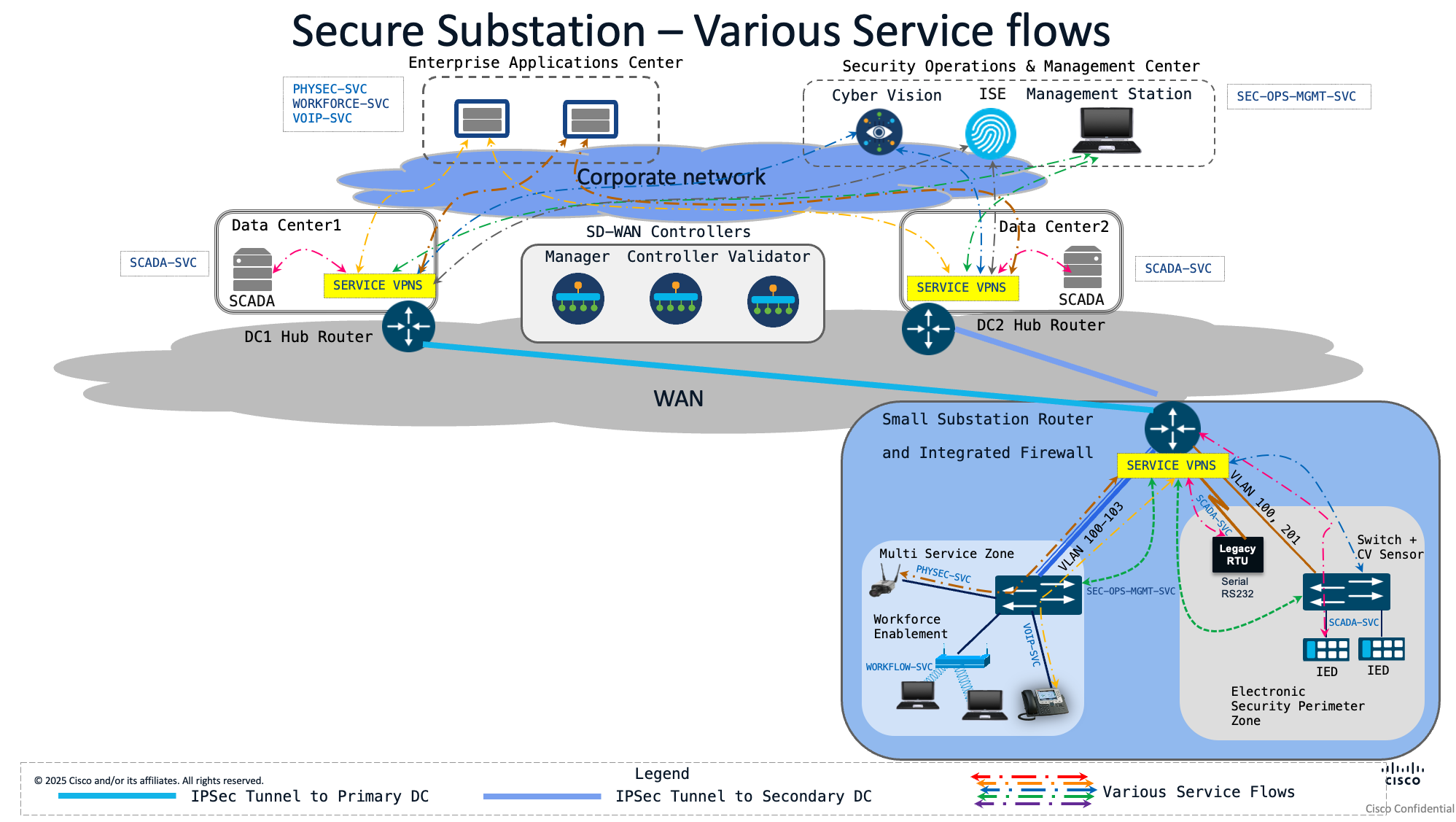 |
Secure Substation – small – Switch Management Service
The following diagram illustrates management access to the switches from the central management station. This established service path is utilized for all management-plane traffic, including SSH, SNMP, and Syslog.
This path is mapped to the SEC-OPS-MGMT-SVC service VPN
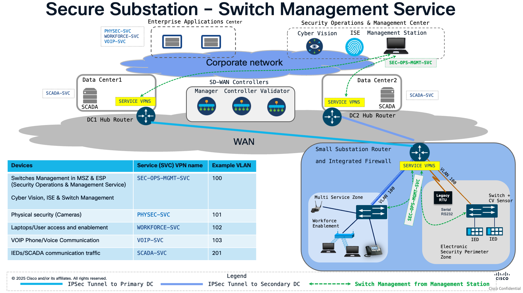
Secure Substation – small – Physical Security and VOIP Services:
The following diagram illustrates the physical security and VoIP service flows extending from the Multi-Service Zone to the Enterprise Application Center.
These traffic flows are isolated and secured using the dedicated Physical Security (PHYSEC-SVC) and Voice (VOIP-SVC) service VPNs
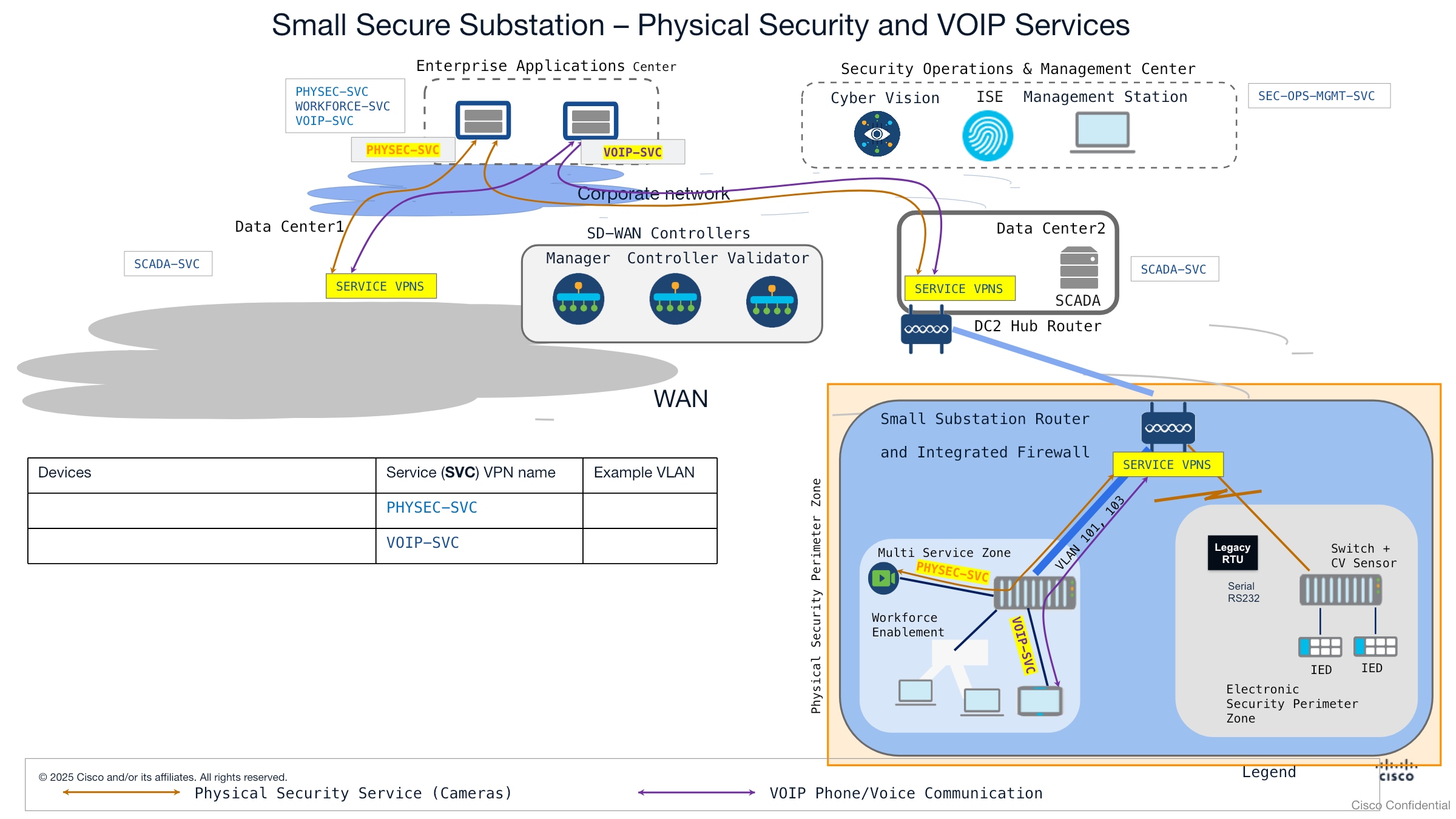 |
Small Secure Substation – Physical security service and VOIP service
Secure Substation – small – Workforce Enablement
The workforce enablement workflow is implemented as a two-stage process to ensure secure, policy-driven connectivity:
Authentication and Authorization:The endpoint performs 802.1X authentication and authorization against the ISE server over theSEC-OPS-MGMT-SVCservice VPN.
Dynamic VLAN Assignment:Upon successful authorization, the device is dynamically transitioned to a dedicated VLAN mapped to theWORKFORCE-SVCservice VPN.
The diagram below illustrates this workflow, showing the service path extending from the Multi-Service Zone to the Enterprise Application Center.
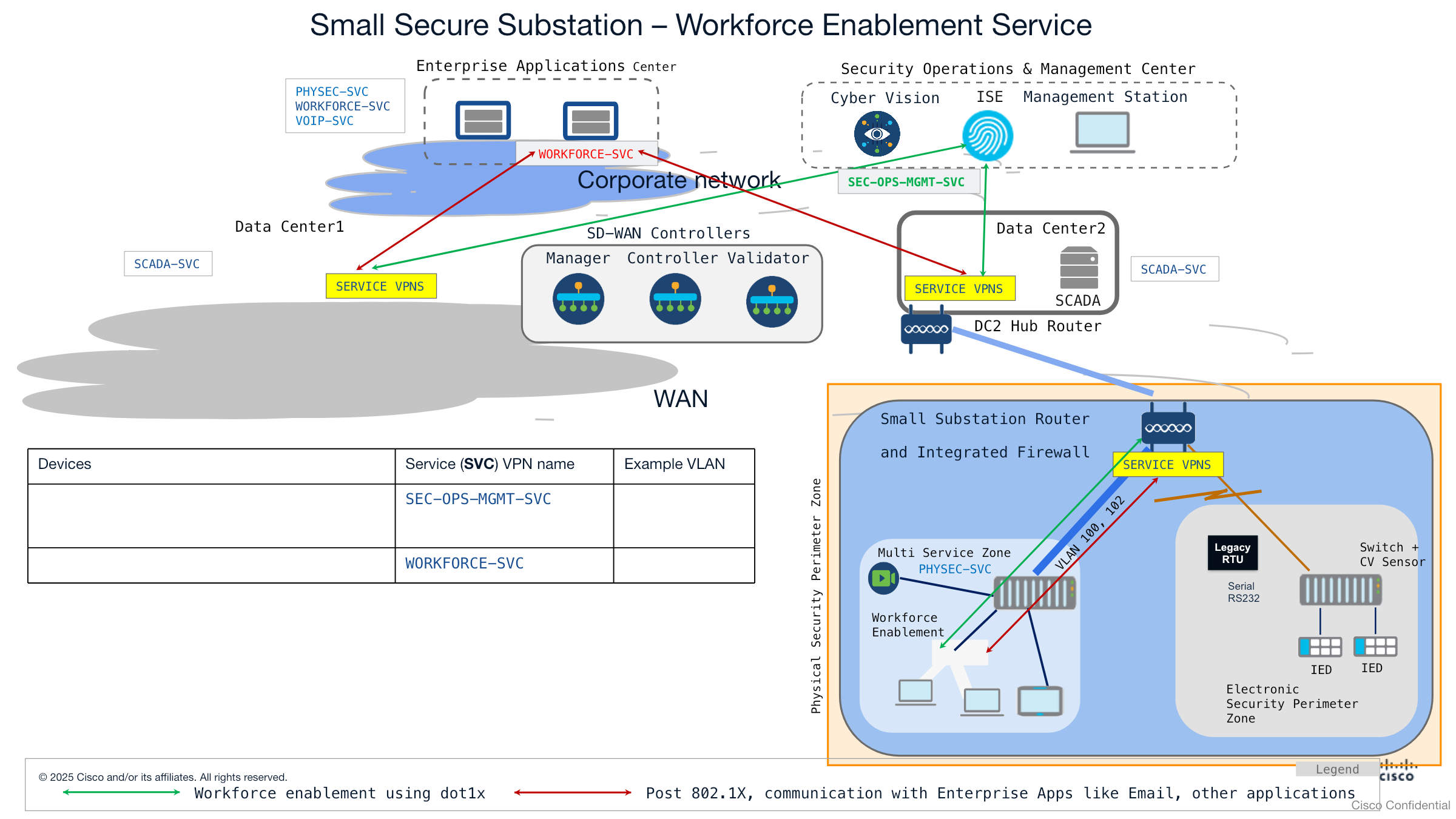 |
SCADA Service flow using Service VPN
This section describes how SCADA traffic flows through the Small Substation architecture using the dedicated SCADA-SVC service VPN. SCADA is the most critical service in the Small Substation design, carrying DNP3-based control and telemetry between substation IEDs/RTUs and the SCADA systems located in the data centres (DC1 and DC2).
The Small Substation supports two distinct SCADA connectivity methods, both carried within the SCADA-SVC service VPN:
IP-based SCADA — For modern Ethernet/IP-connected IEDs in the ESP Zone.
Serial-based SCADA — For legacy serial RTUs, tunnelled over IP using RAW Sockets.
NOTE: The SCADA FEP is architected to communicate exclusively over the SCADA-SVC service VPN. Therefore, all SCADA traffic—whether from IP-capable IEDs or legacy serial RTUs—must be transported via this VPN to ensure end-to-end connectivity.
The small substation router utilizes the SCADA-SVC service VPN to provide a logically isolated and secure path for all SCADA-related traffic. This segmentation ensures that critical grid control communications are separated from non-critical data, meeting the stringent security requirements of utility environments.
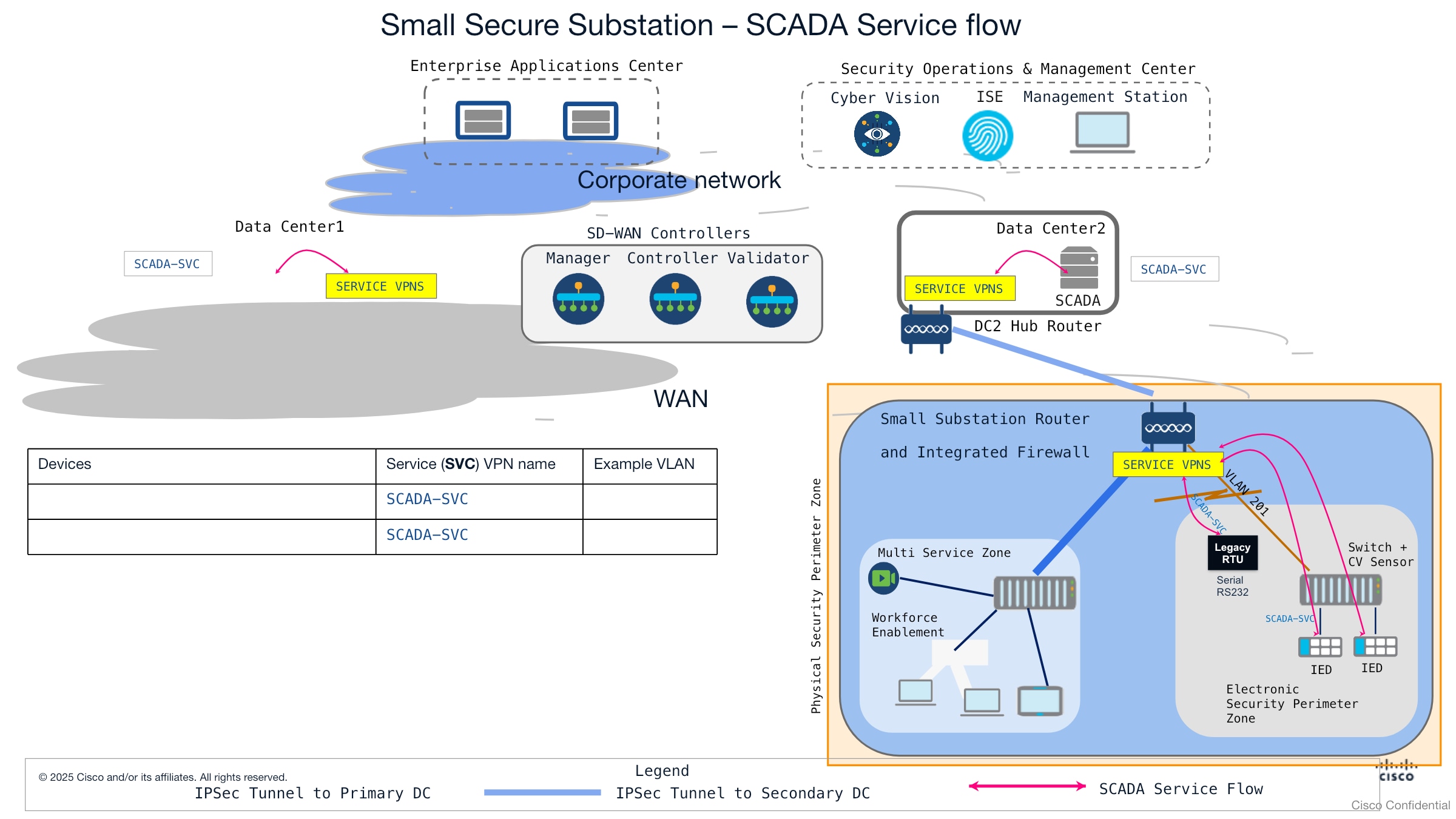 |
1. Native IP-Based SCADA Communication
For modern Intelligent Electronic Devices (IEDs) that support native Ethernet and IP connectivity, the small substation router facilitates direct communication with SCADA FEP in the data centres (DC1 and DC2), with the help of SCADA-SVC service VPN.
Flow Description:
IED (ESP Zone):An Ethernet/IP-capable IED originates DNP3 traffic onto the ESP LAN.
IE3500 switch:Receives the IED traffic on an access port, tags it with SCADA VLAN 201, and forwards it toward the small substation router across the Layer 2 trunk.
IR1101 (ESP boundary device):Terminates VLAN 201 into the SCADA-SVC service VPN. Acting as the ESP boundary device that hosts the Electronic Access Point (EAP), the IR1101 applies the SCADA security policy through its Zone-Based Firewall (ZBFW).
IP-based SCADA traffic, such as DNP3/IP, is mapped directly into the SCADA-SVC service VPN at the small substation router. This ensures a secure, direct communication with the SCADA Front-End Processors (FEPs) located in DC1 and DC2.
2. Legacy Serial SCADA Transport via Raw Sockets
The small substation router integrates legacy Remote Terminal Units (RTUs) by utilizing TCP Raw Socket technology, which wraps raw serial data into standard TCP segments to facilitate IP-based transport.
Flow Description:
Serial RTU— Connects directly to the IR1101 via an async serial interface.
Small Substation Router (TCP RAW Sockets) — The router receives the serial DNP3 data from the RTU and encapsulates it into IP using TCP RAW Sockets, mapping the traffic into the SCADA-SVC service VPN.
WAN transport (IPsec)— The encapsulated serial-over-IP traffic is carried within the SCADA-SVC service VPN and encrypted over the WAN toward DC1 and DC2.
DC1 / DC2 Hub routers— Terminate the IPsec tunnels and place the traffic into the matching SCADA-SVC service VPN.
SCADA systems (data centre)— The RAW Sockets TCP session is terminated and the serial DNP3 data is delivered to the SCADA systems in both data centers, enabling the serial RTU to communicate with SCADA masters located across the two data centers.
Similar to native IP traffic, the encapsulated serial data is transported within the SCADA-SVC service VPN. This maintains consistent security policies across the entire SCADA environment, regardless of whether the underlying device is serial or IP-based.
3. High Availability with Dual Raw Socket Connectivity:
The architecture leverages dual-homed connectivity to enable the small substation router to maintain simultaneous RAW socket sessions with SCADA masters in both the primary and secondary data centers. By establishing these redundant paths, the design eliminates the single point of failure inherent in traditional serial deployments. This provides the high level of reliability required for critical infrastructure, ensuring continuous, real-time grid visibility and control of legacy RTUs, as utilities transition from legacy serial environments to a modernized, IP-based SD-WAN architecture.
The Substation Router as an Integrated Firewall for SCADA
The small substation router additionally performs the role of an integrated firewall, establishing a secure conduit for the Electronic Security Perimeter (ESP). By implementing a Zone-Based policy Firewall (ZBFW), the router provides stateful inspection and granular control of traffic flowing between the other zones, SCADA Zone and the ESP Zone.
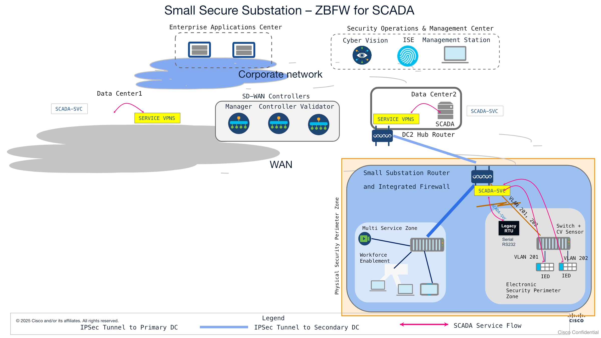 |
Zone Definitions and Segmentation:
● SCADA Zone: Dedicated to SCADA system communications. This zone is mapped exclusively to the SCADA-SVC service VPN to ensure secure, isolated connectivity.
● ESP Zone (Electronic Security Perimeter):Hosts critical infrastructure and Intelligent Electronic Devices (IEDs). This zone is anchored to the Electronic Access Point (EAP) interfaces on the substation router.
● ESP-SUB-ZONES: Provides granular security control by subdividing the ESP-ZONE based on VLAN assignments (e.g., ESP-SUB-ZONE1 for VLAN 201; ESP-SUB-ZONE2 for VLAN 202). This allows for inter-zone policy enforcement between specific IED groups
● MSP-ZONE (Multi-Service Perimeter): Aggregates non-critical services—specifically physical security, workforce mobility, and VoIP—by mapping the PHYSEC-SVC, WORKFORCE-SVC, and VOIP-SVC service VPNs into a single security container.
● ESP Sub-Zones: To support more granular security requirements, the ESP Zone can be further subdivided into sub-zones based on VLAN assignments (e.g., ESP Sub-zone 1 for Interface VLAN 201; ESP Sub-zone 2 for Interface VLAN 202). This way, even the communication between ESP sub zone 1 and ESP sub zone 2 can be controlled with policy.
● SEC-OPS-MGMT-ZONE: Reserved for management-plane traffic, this zone is mapped exclusively to the SEC-OPS-MGMT-SVC service VPN.
Table 14. Security Zone Mapping Reference – An Example
| Security Zone Name |
Associated Service VPN(s) |
Associated Interface |
| SEC-OPS-MGMT- ZONE |
SEC-OPS-MGMT-SVC |
- |
| MSP-ZONE |
PHYSEC-SVC WORKFORCE-SVC VOIP-SVC |
- |
| SCADA-ZONE |
SCADA-SVC |
- |
| ESP-ZONE |
- |
EAP (VLAN 201, VLAN 202) |
| ESP-SUB-ZONE1 |
|
EAP (VLAN 201) |
| ESP-SUB-ZONE2 |
|
EAP (VLAN 202) |
When implementing the ESP-ZONE, choose between a unified ESP-ZONE or granular ESP-SUB-ZONES based on your specific requirements for inter-VLAN traffic inspection. If granular policy enforcement between IED groups is required, the sub-zone approach is recommended.
The Zone-Based Policy Firewall (ZBFW) on the small substation router provides granular security by grouping network segments into logical zones and defining explicit policies for inter-zone communication.
● Security Zones: A security zone represents a logical grouping of network interfaces or Service VPNs that share a common security posture. Multiple interfaces or VPNs can be mapped to a single zone, ensuring consistent security policy application across the substation architecture.
● Zone Pairs: Zone pair configurations define the directional security policies applied to traffic traversing between two distinct zones. Policies are applied unidirectionally, allowing for precise control over traffic flow (e.g., blocking traffic from any "Untrusted" zone to a "Trusted" ESP zone).
● Traffic Classification: The small substation router utilizes class-maps to perform granular traffic classification for ZBFW policy enforcement. Traffic can be classified based on the following criteria:
● Access Control Lists (ACLs): Standard or extended named ACLs that filter traffic based on source/destination IP addresses and port numbers.
● Protocol Matching: Identification of Layer 4 protocols (TCP, UDP, ICMP) and specific application services (e.g., HTTP, DNP3, MODBUS, FTP, SMTP, DNS, Syslog).
● Nested class-maps: Hierarchical class-map structures that allow for complex, multi-criteria matching to support sophisticated security requirements.
"Logging" should be enabled on ZBFW rules to provide the audit trail required for NERC CIP compliance.
ZBFW Roles and DNP3-Specific Security Policies
The following policies are implemented within the ZBFW to secure the Electronic Security Perimeter (ESP):
● Authorized SCADA Master Access Control: The ZBFW enforces stateful inspection of DNP3 traffic (TCP/UDP Port 20000). The policy mandates that connections must be initiated by the authorized SCADA Master located in the data center toward the IEDs in the substation. All unsolicited inbound traffic from unauthorized sources is implicitly dropped.
Note: When defining the zone pair for traffic entering the ESP, configure an explicit permit rule for the authorized SCADA Master IP, followed by an implicit deny for all other traffic.
● Zone Segregation (Lateral Movement Prevention): The ZBFW explicitly denies East-West routing between the Multi-Service Zone (Workforce/Cameras) and the ESP Zone (IEDs). This segmentation mitigates the risk of lateral movement, ensuring that a compromise of a non-critical endpoint—such as an IP camera or workstation—cannot be leveraged to pivot into the ESP and threaten critical IED infrastructure.
● ESP Perimeter Hardening: To minimize the attack surface, the ZBFW enforces a "Default Deny" posture for the ESP Zone. All inter-zone communication directed at the ESP is explicitly blocked unless specifically required and authorized by the security policy, effectively shielding the ESP from unauthorized access originating from other zones or the external network.
Selectively permit the communication from SCADA Zone to ESP Zone using security policy.
The Small Substation design implements a defense-in-depth security model, leveraging Network Access Control (NAC) at the switching layer and Zone-Based Policy Firewall (ZBFW) at the routing layer.
Network Access Control (NAC)
To secure LAN-side access, ports on the IE3100 and IE3500 switches are integrated with Cisco Identity Services Engine (ISE) hosted in the Security Operations & Management Center.
802.1X Authentication:Capable endpoints (with supplicants) must authenticate via 802.1X before being assigned specific security policies, dedicated VLANs, or bandwidth limits.
MAC Authentication Bypass (MAB):For endpoints lacking 802.1X support (e.g., IoT sensors, IP cameras, legacy IP phones), MAB is utilized. Because MAC addresses can be spoofed, it is highly recommended to pair MAB with static IP-MAC-Port bindings or profiling policies in ISE to enforce an additional layer of security.
Visibility and Threat Detection (Cisco Cyber Vision)
To align with NERC CIP 015-1 INSM (Internal Network Security Monitoring) requirements, Cisco Cyber Vision is deployed to provide deep visibility into the substation network.
● Sensor Deployment: The Cyber Vision sensor is hosted as an edge compute application on the IE3500 switch within the ESP.
● Capture Interface: The sensor utilizes a Virtual Port Group (VPG) interface to ingest raw mirrored traffic (SPAN/RSPAN) from the switch backplane without requiring external cabling or additional hardware
● Traffic Monitoring: The Cyber Vision sensor monitors both North-South communication (between the IEDs and the DC SCADA systems) and East-West communication (peer-to-peer GOOSE/MMS between IEDs).
● Collection Network: The Cyber Vision sensor extracts lightweight metadata from the captured traffic and transports it to the Cisco Cyber Vision Center over this network.
● Telemetry Transport: The sensor communicates securely with the Cyber Vision Center (hosted in the SecOps Center) over the dedicated SEC-OPS-MGMT-SVC Service VPN.
● Capabilities: This deployment enables active discovery for DNP3, asset baselining, traffic flow analysis, and so on.
Traffic Profile considered for small substation
The following traffic profile is considered for small substation.
● SCADA Traffic (50–200 points): ~10–50 kbps average throughput. Requires strict priority queuing (LLQ) to ensure low latency.
● Management Traffic: Minimal bandwidth for SSH, SNMP, and Syslog.
● Physical Security (1-3 Cameras):
◦ A standard 1080p IP camera (H.264, 6-10 fps) consumes ~1-2 Mbps.
◦ A high-frame-rate 1080p CCTV camera (H.264, 30 fps) consumes ~2-4 Mbps.
● Total Expected WAN Throughput:Typically ranges between 3 Mbps and 15 Mbps, depending heavily on the physical security video feeds and workforce mobility usage.
Chapter 8 Firewall and Threat Inspection Design
The firewall design should implement the Electronic Security Perimeter (ESP) as a clearly documented set of Electronic Access Points. Communication between security zones must follow the ISA/IEC 62443 zone-and-conduit model and use least-privilege, default-deny policies. Each permitted flow should identify its business purpose, source, destination, protocol, port, direction, inspection requirement, and enforcement point. Management, physical-security, workforce, enterprise, and SCADA services must remain separated.
NGFW Design for IR8340 Deployments
For medium substations, the IR8340 can serve simultaneously as:
● WAN edge router.
● Service VPN/VRF termination point.
● ESP boundary enforcement point.
● ZBFW and integrated NGFW platform.
● UTD IDS/IPS enforcement point where supported by the validated software release.
● Security event and access-log source.
Service VPNs/VRFs provide routing separation, while firewall zones provide the policy boundary.
Assign a dedicated zone when a service has a distinct trust level, destination set, inspection requirement, or operational behavior. Do not combine SCADA, management, workforce, physical-security, and enterprise traffic in the same zone. Multiple interfaces or VLANs may share a zone only when they require identical security treatment.
Use ZBFW as the baseline inter-zone control. Apply NGFW, UTD IDS/IPS, and SCADA protocol inspection only to selected conduits where the operational benefit justifies the processing and failure-domain impact. Route leaking between VRFs must always be paired with firewall policy; routing reachability must not imply application access.
ZBFW Design for IR1101 Deployments
For small substations, the IR1101 should act as the WAN edge and ESP boundary device. A recommended zone model is:
● ESP-ZONE: Electronic Access Point and protected IED/RTU-facing interfaces.
● SCADA-ZONE: Dedicated SCADA-SVC service VPN.
● SEC-OPS-MGMT-ZONE: Device administration, logging, ISE, and security-management services.
● MSP-ZONE: Physical security, workforce, and voice services, provided these services share an approved policy posture.
Zone pairs are directional and must be created only for required communication. Use class maps to classify traffic by source and destination address, Layer 4 protocol, application port, and, where necessary, nested matching criteria.
Apply the following controls:
● Permit SCADA DNP3 sessions only from authorized SCADA masters to approved IEDs, RTUs, or gateways.
● Use an explicit permit for authorized master addresses followed by an implicit deny.
● Deny routing between the multiservice zone and the ESP to prevent lateral movement.
● Permit SCADA-to-ESP communication selectively, not through broad subnet-level rules.
● Enable logging on security-relevant ZBFW rules.
● Maintain a default-deny posture for all traffic directed toward the ESP.
Unified Threat Defense for IDS and IPS
Use IDS mode first when operational traffic has not yet been baselined or when inline blocking could affect grid operations. IDS deployment should establish normal protocol behavior, identify false positives, and validate signature relevance.
Enable IPS blocking only after validating:
● The inspected traffic direction.
● Applicable signatures and rule behavior.
● False-positive handling.
● Latency and throughput impact.
● Platform resource consumption.
● Signature-update and rollback procedures.
● Fail-open, fail-close, or bypass behavior.
● Operational recovery and failback procedures.
Apply prevention selectively to well-understood threats. Detection-only handling is appropriate for ambiguous industrial-protocol events until operations and security teams agree that blocking is safe
Firewall Policy Model for SCADA and DNP3 Traffic
SCADA policy must reflect industrial communication behavior rather than use a generic IT firewall policy. Account for long-lived sessions, periodic polling, telemetry, unsolicited event reporting, and control operations.
Every rule should document:
● Source and destination zones.
● Source and destination addresses.
● Authorized initiator.
● Protocol and destination port.
● Permitted direction.
● Required application or protocol inspection.
● Logging requirement.
● IDS, IPS, or pass action.
● Operational owner and justification.
For DNP3/IP:
● Restrict TCP or UDP port 20000 to known masters and approved outstations.
● Enforce the expected master-to-outstation direction.
● Reject unexpected masters, outstations, and communication direction.
● Separate monitoring-only paths from control-capable paths.
● Avoid broad any-to-any permits between SCADA-SVC and the ESP.
Apply the same source, destination, role, and direction principles to IEC 60870-5-104 and Modbus TCP. Modbus requires especially restrictive controls because it lacks strong native security.
IDS and IPS Policy Design
Inspection policies should be organized by conduit rather than applied indiscriminately to all traffic. Prioritize:
● Control-center-to-substation SCADA conduits.
● ESP ingress and egress.
● Remote and workforce-access paths.
● Management conduits.
● Enterprise-to-OT paths.
● Physical-security paths where they cross trust boundaries.
Maintain separate policy sets for detection and prevention. Document-enabled signatures, disabled signatures, suppressions, thresholds, affected assets, update cadence, rollback method, and the owner authorized to approve blocking.
Custom SNORT Rules for DNP3 Message Inspection
Custom DNP3 rules should focus on deviations from the utility’s documented operating model. Candidate detections include:
● DNP3 traffic from an unauthorized master.
● Communication with an unknown outstation.
● Unexpected communication direction.
● Write, select, operate, or direct-operate activity on monitoring-only paths.
● Unexpected restart, file-transfer, time-setting, or configuration activity.
● Unusual control-command frequency.
● A significant departure from the established polling baseline.
Deploy custom rules in alert-only mode first. Validate them against representative SCADA traffic, maintenance operations, failover events, and recovery procedures before enabling blocking. Rule development must be coordinated with SCADA operations so that legitimate protection or control activity is not interrupted.
For detailed DNP3 inspection using custom snort rules, refer to Implement Deep Packet Inspection of DNP3 Traffic with Cisco Catalyst IR8340 UTD IPS/IDS Functionality.
Integrated Firewall Suitability by Deployment Model
Use the integrated model when:
● Site footprint, power, or cabling is constrained.
● Traffic and zone scale fit the validated router capacity.
● A common network and firewall lifecycle is acceptable.
● Centralized templates can maintain consistent policies.
● The utility accepts routing and firewall functions sharing one failure domain.
It is particularly suitable for the IR1101 small-substation design and compact IR8340 medium-substation deployments.
Discrete Firewall Insertion Options
Use a discrete firewall when the utility requires:
● Dedicated security administration.
● Expanded NGFW inspection capacity or features.
● Independent firewall software and policy lifecycle.
● Separate NOC and SOC ownership.
● Stronger separation between routing and security enforcement.
● Additional policy granularity at the ESP or between major service segments.
Place the firewall so all applicable routable ESP traffic crosses it. Avoid alternate routing or switching paths that bypass enforcement. Coordinate firewall interfaces, zones, route exchange, service VPN/VRF mappings, and SOC log forwarding as one design.
Security Event Monitoring and Troubleshooting
Forward the following events to the SOC or approved monitoring platform:
● Firewall permits, denies, and policy hits.
● IDS/IPS alerts and blocking actions.
● Authentication, 802.1X, and MAB events.
● Configuration changes.
● Router, switch, and system events.
● IPsec tunnel, WAN-path, routing, VRF, and interface state changes.
● Cyber Vision asset, protocol, and anomaly events.
● Time-synchronization failures.
Use trusted, redundant time sources across routers, switches, firewalls, Cyber Vision, ISE, WAN management, and logging platforms. Consistent timestamps are required for incident reconstruction and audit evidence.
This chapter describes the Cisco Cyber Vision design for the Secure Substation architecture. The design provides OT asset visibility, traffic-flow analysis, baseline creation, anomaly detection, change reporting, and security reporting for small and medium transmission substations.
Cyber Vision is used as a monitoring and visibility control. It does not replace firewall enforcement, network segmentation, access control, vulnerability management, or operational procedures. The design should be aligned with the Electronic Security Perimeter, service VPN/VRF model, station LAN topology, and SOC monitoring model defined in the earlier chapters.
Cyber Vision Architecture for Substation Security
Cisco Cyber Vision uses a distributed architecture made up of Centers and Sensors. Sensors are placed close to OT traffic sources in the substation network. They analyze mirrored OT traffic using deep packet inspection and send asset, flow, and security-event metadata to the Cyber Vision Center.
For small and medium substations, the recommended model is a centralized Cyber Vision Center with distributed sensors at substations. The Cyber Vision Center is placed in the OT data center or SOC/security operations environment, while sensors run on the validated Cisco Industrial Ethernet switch platforms used in this guide.
The Cyber Vision design supports the following security outcomes:
● Discovery of OT assets and communication relationships.
● Visibility into east-west communication inside the ESP.
● Visibility into north-south communication where SCADA or other OT flows cross monitored interfaces.
● Identification of unexpected assets, unexpected communication, and changes in observed behavior.
● Baseline creation for known OT communication patterns.
● Event forwarding and reporting to support SOC investigation and compliance evidence.
The Cyber Vision Center should be placed where the SOC, OT security team, and utility operations teams can consume the data without creating unnecessary exposure from the substation network. In this design guide, the preferred placement is the OT data center or the security operations environment connected to the OT data center.
The Center placement should support:
● Sensor enrollment and ongoing communication from substations.
● Access for authorized OT security, SOC, and operations users.
● Integration with logging, SIEM, ticketing, or incident-response workflows where required.
● Knowledge database updates and software lifecycle operations.
● Backup, retention, and recovery processes.
● Time synchronization with sensors and other monitoring systems.
Cyber Vision Center communication should use the management or security operations service VPN/VRF. The Center should not be placed directly in the ESP of a small or medium substation unless a project-specific design requires local operation. Centralized placement reduces the substation footprint and gives the SOC a consistent view across multiple substations.
For larger utility environments, a multi-Center or Global Center model can be considered to aggregate visibility across regions or operating companies. That model should be sized and validated separately from the small and medium substation baseline.
Sensor Placement on IE9300 and IE3505 Platforms
Cyber Vision sensors should be placed where they can observe the traffic required by the security use case while keeping the deployment simple and supportable. This version of the design guide validates Cyber Vision sensor placement on Cisco IE9300 for medium substations and Cisco IE3505 for small substations.
Sensor platform selection should be based on the validated software release, traffic scope, packet rate, mirroring design, and required features. Site size alone is not sufficient. A small substation with a limited number of high-churn flows or mirrored VLANs may require more careful sizing than the physical point count suggests.
The recommended placement approach is:
● Use the IE9300 sensor for the medium substation station LAN, where the primary requirement is east-west visibility between IEDs, RTUs, gateways, PMUs, engineering systems, and other ESP assets.
● Use the IE3505 sensor for the small substation station LAN, where the primary requirement is visibility into a compact ESP-facing LAN.
● Use ERSPAN-based monitoring to present the required station LAN traffic to the Cyber Vision sensor on the IE9300 or IE3505 platform.
● Keep the sensor collection path separate from SCADA control traffic by using the management or security operations service VPN/VRF.
● Confirm that sensor clocking, Center reachability, IOx hosting, storage, and software package requirements are satisfied before deployment.
The IR8340 is not used as the Cyber Vision sensor-hosting platform in this version of the integrated firewall design. In the integrated firewall scenario, the IR8340 provides WAN edge, segmentation, firewall, and serial connectivity functions, while Cyber Vision sensing is provided by the station LAN switch.
The monitored traffic scope should be intentional. Mirroring every VLAN or trunk can overload the sensor and may not improve security outcomes. The design should capture the traffic required to monitor the intended ESP, conduits, station LAN segments, and external communication paths.
East-West Visibility within the ESP
East-west visibility refers to traffic between systems inside the substation protected OT environment. In a small or medium substation, this commonly includes traffic between IEDs, RTUs, protection relays, station gateways, PMU devices, engineering workstations, and other station LAN endpoints.
The recommended design is to monitor east-west traffic from the station LAN switch. In the medium substation model, the IE9300 station LAN switch is the primary monitoring point for LAN-connected ESP assets. In the small substation model, the IE3505 provides the station LAN monitoring point. The sensor observes mirrored traffic and sends metadata to the Cyber Vision Center over the security operations or management service VPN/VRF.
East-west monitoring should focus on:
● Expected communication between SCADA-facing gateways and OT devices.
● Engineering workstation access to protected OT devices.
● IED, RTU, gateway, and PMU communication relationships.
● Unexpected peer-to-peer communication inside the ESP.
● New devices or components appearing on the station LAN.
● Protocols or flows that do not match the expected station LAN baseline.
Visibility is limited to traffic that reaches the monitored switch or is mirrored to the sensor. Serial traffic directly attached to the IR8340 is not visible to the IE9300 or IE3505 sensor unless the corresponding IP-encapsulated flow traverses a monitored LAN path.
North-South Visibility for SCADA Traffic
North-south visibility refers to communication between the substation and systems outside the local ESP, such as SCADA masters, front-end processors, OT data center applications, SOC tools, NOC systems, or approved support services.
For SCADA monitoring and control, Cyber Vision should observe the unencrypted OT traffic at a point where protocol context is still available. In many substation designs, this is the station LAN side of the router or firewall, not the encrypted WAN overlay. If the traffic is encrypted before it reaches the sensor, Cyber Vision can see only the outer transport characteristics and cannot decode the underlying industrial protocol.
North-south visibility should be designed around the traffic path:
● SCADA traffic that traverses the IE9300 or IE3505 station LAN can be monitored from the station LAN sensor.
● SCADA traffic routed directly through the IR8340 is not visible to Cyber Vision unless the unencrypted flow is mirrored to the IE9300 or IE3505 sensor before WAN encryption or forwarding.
● Traffic crossing a discrete firewall can be monitored on the protected side, the WAN side, or both, depending on the inspection objective and performance limits.
● Raw socket or serial-over-IP traffic should be monitored only where the IP flow is available to the sensor.
The design should avoid treating Cyber Vision monitoring as a routing or firewall function. Cyber Vision provides visibility and event generation; policy enforcement remains with the firewall, ZBFW, NGFW, ACLs, service VPN/VRF policy, and access-control systems.
Cyber Vision builds inventory by observing industrial traffic, identifying components and devices, and correlating observed properties such as MAC address, IP address, protocol attributes, vendor identifiers, model information, firmware information where available, and communication behavior.
In the Secure Substation design, asset inventory should be organized around the utility's operational model:
● Substation name and location.
● ESP or protected OT environment.
● SCADA, PMU, physical security, workforce access, and management service segments.
● Device type, vendor, model, role, criticality, and owner.
● Communication relationships and external destinations.
● Expected protocol usage and approved control paths.
Cyber Vision inventory should complement the utility's system-of-record inventory. It can identify assets and communication that are not present in the documented inventory, but inventory reconciliation remains an operational process owned by the utility.
OT Asset Vulnerability Visibility
Cyber Vision can provide vulnerability visibility by correlating observed device and component properties with rules in the Cyber Vision Knowledge database. This capability can help operations and security teams identify devices that may require patching, compensating controls, replacement planning, or further investigation.
This design guide should position vulnerability visibility as an operational awareness capability, not as a replacement for the utility vulnerability management program. Vulnerability results depend on asset identification quality, available device properties, Knowledge database currency, and the traffic or active discovery data available to Cyber Vision.
The recommended design treatment is:
● Use Cyber Vision vulnerability visibility to support OT asset review and risk prioritization.
● Keep the Cyber Vision Knowledge database current according to the utility's change-management process.
● Review vulnerability findings with OT engineering before assigning remediation actions.
● Use compensating controls when patching or replacement is not immediately possible.
● Avoid making compliance claims based only on Cyber Vision vulnerability visibility.
Cyber Vision represents communication between devices and components as activities and flows. This provides a practical way to understand who is communicating, which protocol is used, when the communication occurs, how much traffic is exchanged, and whether the behavior aligns with the expected service model.
For substations, traffic-flow analysis should focus on:
● Control center to substation SCADA communication.
● IED, RTU, gateway, and PMU communication relationships.
● Engineering workstation access to OT devices.
● Physical security traffic and video-related flows where monitored.
● Management and security operations traffic.
● External communication initiated from inside the protected OT environment.
● New, rare, or unsupported protocols on monitored substation segments.
Flow analysis should be used to validate zone-and-conduit assumptions. If Cyber Vision observes traffic that does not match the documented firewall, VLAN, service VPN/VRF, or ESP boundary design, the finding should trigger review by the network, OT, and security teams.
Baseline Creation and Change Reporting
Substation communication is typically more predictable than enterprise user traffic. SCADA polling, IED communication, PMU streaming, engineering access windows, and management traffic usually follow known patterns. Cyber Vision should be used to establish a baseline for each monitored substation or group of substations.
The baseline should identify:
● Known devices and components.
● Expected source and destination relationships.
● Expected protocols, ports, and flow direction.
● Expected SCADA masters, outstations, gateways, and PMU destinations.
● Expected engineering and workforce access paths.
● Expected management, logging, time synchronization, and software lifecycle traffic.
Change reporting should focus on meaningful deviations from the baseline. Examples include a new device in the ESP, a new external destination, a new protocol, a communication relationship that crosses an unexpected service boundary, or a material change in flow volume. Change findings should be reviewed with OT operations before enforcement or remediation action is taken.
Cyber Vision anomaly detection should be used to identify changes in behavior inside the protected OT environment. Anomalies may indicate a configuration change, maintenance activity, asset replacement, a misconfigured system, or suspicious activity.
The design should use anomaly detection to support the following workflows:
● Identify new devices or components inside the ESP.
● Detect unexpected communication between protected OT assets.
● Detect unexpected communication from ESP assets to external destinations.
● Identify protocol changes or abnormal flow patterns.
● Alert on behavior that violates the expected station LAN or SCADA baseline.
● Support SOC investigation with asset, flow, event, and vulnerability context.
Anomaly detection should be tuned with input from OT operations. Transmission substation maintenance windows, testing activities, firmware updates, engineering access, and protection changes can generate legitimate changes in observed behavior.
Active Discovery can be used to enrich device visibility when passive monitoring does not provide enough asset detail. It is an optional capability and should be used carefully because it sends discovery traffic into the OT network.
Passive discovery should remain the default visibility method. During normal operations, some OT endpoints may not expose details such as model, serial number, firmware, device type, or other device attributes. Those details may appear only during engineering-station access, browsing, configuration activity, or other infrequent maintenance workflows. Active Discovery provides a controlled way to request additional information from known or partially known devices instead of waiting for those attributes to appear passively.
The recommended placement is to run Active Discovery from the Cyber Vision sensor located on the station LAN switch inside the ESP. For this design guide, that means the IE3505 sensor in the small substation model and the IE9300 sensor in the medium substation model. This keeps the discovery source close to the OT endpoints and avoids requiring new ESP firewall rules for discovery traffic when the sensor and target devices are inside the same protected OT environment.
Active Discovery can use broadcast or unicast discovery depending on the protocol and target scope. Broadcast discovery requires the sensor to have direct access to the target subnet or VLAN. Unicast discovery can be used for known devices in the same subnet or in another reachable OT subnet, provided the Active Discovery interface has the required VLAN, gateway, or route to reach the target devices. The sensor networking design should account for the collection VLAN used for sensor-to-Center communication, the Active Discovery VLAN or routed interface used to reach target devices, and the ERSPAN-based mirrored traffic path used for passive monitoring.
DNP3 is a relevant SCADA example for utility substations. DNP3 Active Discovery uses a unicast model and can help enrich visibility for DNP3 IEDs, RTUs, or other DNP3 endpoints when passive monitoring does not provide enough detail. Other supported Active Discovery protocols should be enabled only when they match the devices and operational requirements of the monitored substation.
In this design, Active Discovery should be considered only when:
● The utility has approved active probing of the target OT subnet or device list.
● The target devices, protocol roles, addressing, and maintenance windows are understood.
● The sensor has the required routed or directly connected access to the target devices.
● The active discovery policy is scoped to approved IP addresses, presets, or subnets.
● Target devices are configured, where required, to respond to the Cyber Vision sensor as an approved requester.
● OT operations have reviewed the expected device behaviour and rollback plan.
Active Discovery should not be treated as a default discovery method for every substation or every protocol. Passive observation should be used first. Active Discovery is most useful for controlled enrichment of known or partially known devices when the utility needs additional device properties. Findings from Active Discovery can improve asset inventory quality, support baseline creation, help correlate vulnerability visibility, and provide better context for firewall and SCADA policy review.
Cyber Vision reports can support operational review, security posture assessment, and evidence collection. Reporting should be aligned to the utility's NERC CIP and internal governance process, but Cyber Vision reports do not by themselves establish compliance.
Useful reporting options include:
● Device inventory reports for asset review and inventory reconciliation.
● Security posture reports for vulnerabilities, risky activities, and security events.
● Remote access reports where remote access gateways and related activities are monitored.
● Change reports showing new devices, new communication relationships, or changes in behavior.
● Event reports for SOC investigation and incident-response workflows.
Reports should be scoped using presets that match the substation, ESP, service segment, or operating region being reviewed. Report output should be retained according to the utility's evidence-retention and audit process.
Cyber Vision Deployment Guidance by Substation Model
Cyber Vision deployment should match the substation model and the visibility objective.
For a small substation, the primary objective is usually asset discovery and basic traffic visibility across a compact station LAN. In this version of the design guide, the IE3505 is the validated Cyber Vision sensor platform for the small substation model. The sensor should monitor the ESP-facing station LAN and the SCADA handoff where technically feasible.
Recommended guidance:
● Use the IE3505 sensor placement when the station LAN is compact and traffic can be mirrored without overload.
● Prioritize visibility into SCADA, IED, RTU, management, and workforce access traffic.
● Use the security operations or management service VPN/VRF for sensor-to-Center communication.
● Avoid broad mirroring if the platform capacity or WAN bandwidth does not support it.
For a medium substation, the primary objective is broader east-west visibility inside the ESP and better separation of monitored services. In the validated medium topology, the IE9300 station LAN switch is the Cyber Vision sensor placement for LAN-connected OT assets.
Recommended guidance:
● Use the IE9300 station LAN sensor for east-west visibility inside the ESP.
● Monitor SCADA and station LAN traffic where it traverses the station LAN switch.
● Do not use the IR8340 as the Cyber Vision sensor host in the integrated firewall scenario.
● Do not claim visibility for serial traffic directly attached to the IR8340 unless the IP-encapsulated flow traverses the monitored IE9300 station LAN path.
● Keep Cyber Vision collection traffic separate from SCADA control traffic.
For utilities monitoring many substations, Cyber Vision deployment should use consistent naming, grouping, presets, and reporting conventions. Substations should be grouped by region, control center, voltage class, operating company, or security scope as appropriate.
Recommended guidance:
● Use common naming conventions for substations, sensors, service segments, and device roles.
● Build presets for each substation and for cross-substation operational views.
● Forward significant security events to the SOC or SIEM where integrated.
● Size Centers, storage, retention, and sensor traffic with margin for growth.
● Validate that sensor-to-Center communication does not affect SCADA or PMU service performance.
Cyber Vision provides the visibility layer for the Secure Substation architecture. The Center is placed centrally in the OT data center or SOC/security operations environment, while sensors are placed at the substation to observe the required ESP, station LAN, and SCADA traffic paths. This version of the design guide uses IE3505 as the Cyber Vision sensor platform for small substations and IE9300 as the Cyber Vision sensor platform for medium substations.
The design should prioritize visibility into assets, flows, baseline behavior, anomalies, and reportable changes. Sensor placement must follow the actual traffic path: a sensor can analyze only the traffic that is mirrored or otherwise delivered to it. For small and medium substations, this means station LAN visibility is the primary use case, with north-south and serial-over-IP visibility added only where the validated topology provides the necessary observation point.
Chapter 10 Validated Design Summary
This chapter summarizes the validated Secure Substation design for small and medium transmission substation deployments. It is intended to provide a concise closeout of the solution scope, validated building blocks, traffic and segmentation model, security controls, visibility design, and operational outcomes described in the preceding chapters.
The Secure Substation design guide validates a repeatable architecture for securing substation communications between the OT data center, SOC, NOC, WAN aggregation layer, and substation sites. The design aligns with NERC CIP and ISA/IEC 62443 principles by applying controlled electronic access, segmentation, secure conduits, monitoring, logging, and defense-in-depth across the supported substation models.
This version of the guide focuses on small and medium transmission substations. The validated scope includes substation WAN connectivity, service segmentation, integrated and discrete firewall models, station LAN connectivity, SCADA protocol handling, legacy serial integration, Cyber Vision visibility, and centralized operations using Catalyst WAN Manager where applicable.
The validated design includes the following scope:
● Small and medium transmission substation models.
● WAN spoke connectivity from substations to primary and secondary OT data center WAN edge hubs.
● Catalyst WAN Manager-based operation for supported WAN edge lifecycle functions.
● Service VPN/VRF segmentation for SCADA, physical security, workforce access, management, security operations, PMU, voice, enterprise, and legacy serial services.
● Integrated firewall model using the substation WAN edge router as the ESP boundary enforcement point.
● Discrete firewall model using a dedicated firewall at the ESP boundary or protected service boundary.
● Station LAN connectivity using Cisco Industrial Ethernet switching.
● Cyber Vision visibility using switch-hosted sensors in the validated small and medium substation models.
● DNP3, Modbus TCP, IEC 60870-5-104, IEC 61850 MMS, ICCP, IEEE C37.118, HTTPS, SCP, SSH, and supported serial transport use cases where applicable.
This version of the guide does not validate every possible substation design variation. Items outside the baseline scope should be handled as project-specific extensions and validated separately.
The following items are not part of this validated scope:
● Large and EHV transmission substation designs.
● Process bus designs based on IEC 61850 GOOSE and Sampled Values.
● Autonomous SD-WAN deployment models.
● IR8340-based Cyber Vision sensor hosting in the integrated firewall scenario.
● Broad WAN transport models outside the validated fiber, MPLS/SR, and Cellular/LTE scope.
● Detailed compliance attestation or audit evidence packages.
● Final product and software release selection, which must be completed from the validation record.
Validated Architecture Building Blocks
The validated architecture uses a hub-and-spoke model. OT data centers provide SCADA, control center, and related operational applications. The SOC consumes security telemetry from Cyber Vision, firewall functions, IDS/IPS, identity services, and infrastructure logs. The NOC operates WAN and infrastructure lifecycle functions, including Catalyst WAN Manager.
At the substation, the WAN edge router connects the site to the utility WAN and aggregates local services. The station LAN switch connects OT endpoints and provides the Cyber Vision sensor placement for east-west visibility. Firewall enforcement is provided either by the integrated firewall function on the substation WAN edge router or by a discrete firewall placed at the protected boundary.
The validated building blocks are:
● OT data center services for SCADA, control center, and operational applications.
● SOC and security operations services for monitoring, event review, and incident-response workflows.
● NOC and Catalyst WAN Manager services for supported WAN edge operations.
● OT data center WAN edge hubs for substation aggregation.
● Substation WAN edge router for spoke connectivity, segmentation, and service handoff.
● Station LAN switch for OT endpoint connectivity and Cyber Vision sensor placement.
● Integrated or discrete firewall enforcement at the ESP or protected service boundary.
● Cyber Vision Center and distributed switch-hosted Cyber Vision sensors.
Substation Model Summary
The small substation model is optimized for compact station LAN environments with lower point counts and simpler service separation requirements. The design uses a small-footprint substation architecture with WAN connectivity, protected OT access, service segmentation, and Cyber Vision visibility using the IE3505 sensor placement.
The medium substation model supports a larger station LAN, higher point count, broader service separation, PMU traffic where deployed, and integrated or discrete firewall options. The medium model uses the IR8340 as the substation WAN edge router. In the integrated firewall option, the IR8340 also acts as the ESP boundary enforcement point. Cyber Vision visibility is provided from the station LAN switch using the IE9300 sensor placement.
Both models follow the same architecture principles:
● Keep the ESP boundary clear and enforceable.
● Separate SCADA control traffic from management, physical security, workforce, enterprise, and support services.
● Use service VPNs implemented as VRFs for routing separation.
● Align VLANs, VRFs, firewall zones, and application destinations.
● Monitor station LAN traffic with Cyber Vision where the validated topology provides the required visibility point.
● Forward security-relevant telemetry to the SOC or approved security monitoring platform.
The validated design uses service VPNs implemented as VRFs to keep services separated across the substation, WAN, and OT data center aggregation layer. VLANs provide local Layer 2 separation on the station LAN, while routed interfaces, subinterfaces, service VPNs/VRFs, and firewall zones provide Layer 3 segmentation and policy enforcement.
Typical service segmentation includes:
Table 15. Service Area, Segmentation Intent
| Service Area |
Segmentation Intent |
| SCADA and protected OT services |
Carry monitoring and control traffic between approved control center systems and protected substation OT assets. |
| PMU services |
Carry synchrophasor traffic separately or aligned with SCADA based on bandwidth, policy, and destination requirements. |
| Physical security services |
Separate camera, badge, door controller, and video traffic from SCADA control traffic. |
| Workforce access services |
Provide controlled access for engineering, field technician, and approved remote access workflows. |
| Management and security operations |
Carry device administration, ISE, Cyber Vision, logging, backup, telemetry, and software lifecycle traffic. |
| Enterprise or corporate services |
Support approved enterprise-to-substation integrations through controlled conduits. |
| Legacy serial services |
Carry raw socket or serial pseudowire traffic aligned to the protected OT service it supports. |
Service separation does not replace firewall policy. The firewall or ZBFW policy enforces the allowed conduits between services, zones, and destinations.
Firewall and Threat Inspection Summary
The validated design supports integrated and discrete firewall models.
In the integrated firewall model, the substation WAN edge router provides WAN connectivity, service VPN/VRF termination, segmentation, and firewall enforcement. This model reduces footprint and is suited to small and medium substations where the validated platform provides the required routing, security, and performance capability.
In the discrete firewall model, a dedicated firewall provides the ESP or protected boundary enforcement point. The substation WAN edge router remains the WAN edge and service aggregation point. This model can be selected when the utility requires a dedicated security enforcement platform, separate firewall lifecycle, or stronger operational separation between WAN and security functions.
Threat inspection is applied where it supports the zone-and-conduit model. Detailed firewall policy, IDS/IPS mode selection, DNP3 inspection behavior, custom Snort rules, signature update process, and blocking criteria are covered in the Firewall and Threat Inspection Design chapter.
Cyber Vision Visibility Summary
Cyber Vision provides the visibility layer for the validated design. The Cyber Vision Center is placed centrally in the OT data center or SOC/security operations environment. Sensors are placed at substations on validated Industrial Ethernet switch platforms.
This version of the guide uses:
● IE3505 as the Cyber Vision sensor platform for small substations.
● IE9300 as the Cyber Vision sensor platform for medium substations.
The IR8340 is not used as the Cyber Vision sensor host in the integrated firewall scenario. In that design, the IR8340 provides WAN edge, segmentation, firewall, and serial connectivity functions, while Cyber Vision sensing is provided from the station LAN switch.
Cyber Vision visibility supports:
● OT asset discovery and inventory reconciliation.
● East-west visibility inside the ESP.
● North-south visibility for SCADA traffic where the unencrypted flow traverses a monitored point.
● Baseline creation for normal communication behavior.
● Change reporting for new devices, new flows, and unexpected communication.
● Anomaly detection and event forwarding to the SOC.
● Active Discovery for controlled enrichment of OT device information, with DNP3 used as a relevant SCADA protocol example.
Visibility is limited to traffic that reaches the monitored switch or is mirrored to the sensor. Serial traffic directly attached to the IR8340 is not visible to the IE9300 or IE3505 sensor unless the corresponding IP-encapsulated flow traverses a monitored LAN path.
Traffic Profile Summary
The validated traffic profile reflects small and medium transmission substation use cases. Detailed traffic assumptions, WAN transport considerations, service VPN/VRF mapping, and sizing guidance are covered in the applicable substation design, WAN aggregation, and service segmentation chapters.
At summary level, the design supports SCADA, PMU where deployed, Cyber Vision telemetry, physical security, workforce access, management, logging, software lifecycle, and legacy serial transport across the validated fiber, MPLS/SR, and Cellular/LTE WAN transport scope.
Operations and Monitoring Summary
The validated design separates operations domains across OT data center, SOC, NOC, and substation responsibilities. The OT data center hosts control and operational applications. The SOC consumes security telemetry and investigates security events. The NOC operates WAN and infrastructure services, including Catalyst WAN Manager where applicable. Field and OT engineering teams maintain substation devices and approved workflows.
Operational telemetry should include:
● Firewall events and policy hits.
● IDS and IPS events where deployed.
● Catalyst WAN Manager device and tunnel state.
● Router and switch syslog.
● Authentication events from Cisco ISE or the approved identity platform.
● 802.1X and MAB success and failure events.
● Cyber Vision asset, flow, vulnerability, anomaly, and security events.
● VPN, VRF, routing, and interface state changes.
● Configuration change events.
● Time synchronization status.
Time synchronization is required so that events from substations, OT data centers, SOC systems, NOC platforms, and logging systems can be correlated during operations and incident response.
Validation Summary
The validated design confirms the architecture pattern and design intent for small and medium secure substation deployments. Product identifiers, software releases, topology details, scale assumptions, traffic profiles, and test results are documented in the applicable design chapters and validation record.
Chapter 10 does not restate those details. It summarizes the validated outcome: a repeatable secure substation architecture with WAN aggregation, service VPN/VRF segmentation, ESP boundary enforcement, firewall and threat inspection placement, Cyber Vision visibility, and operations integration across the supported small and medium substation models.
Design Summary
The Secure Substation design guide provides a validated architecture for small and medium transmission substations that require secure WAN connectivity, controlled ESP access, service segmentation, firewall enforcement, Cyber Vision visibility, and SOC/NOC operational integration.
The design uses a consistent framework:
● OT data center WAN edge hubs aggregate small and medium substation spokes.
● Substation WAN edge routers provide WAN connectivity and service segmentation.
● Service VPNs implemented as VRFs separate traffic by function and trust level.
● Integrated or discrete firewalls enforce approved conduits.
● Industrial Ethernet switches provide station LAN connectivity and Cyber Vision sensor placement.
● Cyber Vision provides asset, flow, baseline, anomaly, and reporting visibility.
● Logs and telemetry are forwarded to operations and security monitoring platforms.
This design establishes the validated baseline for the guide. Any extension beyond the validated scope, such as large substation process bus, alternate sensor placement, autonomous SD-WAN operation, or additional WAN transport models, should be treated as a separate design validation activity.
Appendix A Reference Documents
This appendix lists the primary reference documents used to author the Secure Substation design guide. The documents are grouped by design area so that readers can locate the source material for architecture, WAN segmentation, firewall and threat inspection, Cyber Vision visibility, product configuration, and industry standards.
Cisco Validated Design and Solution References
1. Cisco Industry Validated Design guides
Reference landing page for Cisco industry validated designs, including utilities, substation automation, distribution automation, grid security, and industrial security design guides.
2. Cisco Substation Automation - The New Digital Substation Version 3.3 Design guide
Reference for substation automation architecture, station LAN concepts, ESP/multiservice/corporate zone placement, and substation automation design patterns.
3. Cisco Substation Automation Utility WAN Solution Guide
Reference for substation WAN architecture, WAN aggregation, utility WAN services, and substation backhaul design considerations. This guide is available from the Cisco Industry Validated Design guides page.
Reference for IR8340-based DNP3 inspection, UTD IDS/IPS, custom Snort rules, and SCADA protocol inspection design.
5. Cisco Cyber Vision Active Discovery for DNP3 Devices White Paper
Reference for Cyber Vision Active Discovery concepts using DNP3 as a utility SCADA protocol example.
Cisco Catalyst WAN and Security References
1. Cisco Catalyst SD-WAN Onboarding Guide, Releases 26.x and Later
Reference for Catalyst WAN Manager onboarding, first-time setup, controller initialization, and WAN edge onboarding workflows.
2. Cisco Catalyst SD-WAN Network Configuration Guide, Releases 26.x and Later - VPN
Reference for transport VPN, management VPN, service VPN, and VPN-based segmentation concepts used by Catalyst WAN deployments.
3. Cisco Catalyst SD-WAN Network Configuration Guide, Releases 26.x and Later - Configure VPN
Reference for configuration groups, templates, and CLI-based VPN configuration, including service VPN configuration.
4. Cisco Catalyst SD-WAN Security Configuration Guide, Releases 26.x and Later - Enterprise Firewall with Application Awareness
Reference for zone-based firewall, firewall policy, zone pairs, VPN-to-zone mapping, unified security policy, and firewall logging.
5. Cisco Catalyst SD-WAN Security Configuration Guide, Cisco IOS XE Catalyst SD-WAN Release 17.x - Security Virtual Image
Reference for UTD, IDS/IPS, security virtual image lifecycle, and signature-based threat inspection on supported IOS XE Catalyst SD-WAN devices.
6. Cisco IOS XE Catalyst SD-WAN Qualified Command Reference Guide - Zone Based Firewall Commands
Reference for zone-based firewall command behavior and CLI syntax where CLI templates or supplemental configuration are used.
1. Cisco Cyber Vision Architecture Guide, Release 5.0.0
Reference for Cyber Vision Center and sensor architecture, OT visibility design, asset inventory, communication maps, anomaly detection, and security monitoring concepts.
2. Cisco Cyber Vision Administration Guide, Release 5.x
Reference for Cyber Vision administration, system operation, Center management, sensor management, events, and integrations.
3. Cisco Cyber Vision GUI User Guide, Release 5.x
Reference for asset inventory, activity maps, vulnerabilities, events, baselines, and user-facing Cyber Vision workflows.
https://www.cisco.com/c/en/us/support/security/cyber-vision/products-user-guide-list.html
4. Deploy Cisco Cyber Vision Sensor on Switches and Routers
Reference for Cyber Vision sensor deployment on supported switch and router platforms, OT traffic monitoring, ERSPAN/RSPAN options, provisioning, and sensor application setup.
5. Cisco Cyber Vision Active Discovery Configuration Guide, Release 5.x
Reference for Active Discovery configuration, sensor selection, passive-only versus passive-and-active modes, and controlled enrichment of OT asset data.
6. Cisco Catalyst SD-WAN Solution Integrations Guide, Releases 26.x and Later - Cisco Cyber Vision Integration with Cisco Catalyst SD-WAN
Reference for Cyber Vision integration with Cisco Catalyst SD-WAN Manager and supported integration workflows.
1. Cisco Catalyst IR8300 Rugged Series Router - Configuration Guides
Reference page for Cisco Catalyst IR8340 Rugged Series Router software configuration guides, release notes, timing, synchronization, and platform configuration.
2. Cisco Catalyst IR8340 Rugged Series Router Hardware Installation Guide
Reference for IR8340 hardware installation, environmental specifications, power, physical specifications, modules, and platform installation requirements.
3. Cisco Catalyst IE9300 Rugged Series Data Sheet
Reference for IE9300 platform capabilities, industrial switching features, ruggedized deployment characteristics, and Cyber Vision-related platform support.
4. Cisco Catalyst IE9300 Rugged Series Switches - Support Documentation
Reference page for IE9300 release notes, security configuration, redundancy protocol configuration, installation, and platform support documentation.
https://www.cisco.com/c/en/us/support/switches/catalyst-ie9300-rugged-series/series.html
5. Cisco IE3500 Rugged Series Data Sheet
Reference for IE3500 and IE3505 platform capabilities, industrial switching features, scale, power, and platform specifications.
Industry Standards and Protocol References
1. NERC Critical Infrastructure Protection Reliability Standards
Reference for NERC CIP requirements used to align ESP, EAP, EACMS, PACS, Intermediate System, access control, monitoring, change management, recovery, and evidence-oriented design practices.
https://www.nerc.com/standards/reliability-standards/cip
2. ISA/IEC 62443 Series of Standards
Reference for industrial automation and control system cybersecurity concepts, including defense-in-depth, zones and conduits, risk-based segmentation, system security requirements, and lifecycle security practices.
https://www.isa.org/standards-and-publications/isa-standards/isa-iec-62443-series-of-standards
3. IEC 61850 Series - Communication Networks and Systems for Power Utility Automation
Reference for substation automation communication models, station bus concepts, IEC 61850 MMS, and utility automation communication requirements.
https://webstore.iec.ch/en/publication/75090
4. IEC 60870-5 Series - Telecontrol Equipment and Systems, Transmission Protocols
Reference for IEC 60870-5-104 and related telecontrol protocol specifications.
https://webstore.iec.ch/en/publication/3755
5. IEEE Std 1815 - Electric Power Systems Communications, Distributed Network Protocol (DNP3)
Reference for DNP3 protocol structure, functions, application options, and interoperability expectations.
https://standards.ieee.org/ieee/1815/6177/
6. Modbus Application Protocol Specification and Modbus Messaging on TCP/IP Implementation Guide
Reference for Modbus application protocol, Modbus TCP/IP messaging, and Modbus security protocol documentation.
https://www.modbus.org/modbus-specifications
7. IEEE/IEC 60255-118-1-2018 - Synchrophasor for Power Systems, Measurements
Reference for synchrophasor measurement requirements and PMU measurement concepts.
https://standards.ieee.org/ieee/60255-118-1/5724/
8. IEEE C37.118.2-2024 - Synchrophasor Data Transfer for Power Systems
Reference for real-time synchrophasor data transfer between PMUs, phasor data concentrators, and related applications.
https://standards.ieee.org/ieee/C37.118.2/7077/
Table 17 lists the acronyms and initialisms that may have been used in this SA design guide version 3.2:
Table 16. Acronyms
| Acronym |
Definition |
| AAA |
Authentication, Authorization, and Accounting |
| ACL |
Access Control List |
| AP |
Access Point |
| CBWFQ |
Class-Based Weighted Fair Queuing |
| CE |
Carrier Ethernet |
| CG |
Connected Grid |
| CIP |
Critical Infrastructure Protection |
| CLI |
Command-Line Interface |
| CoS |
Class of Service |
| CorpSS |
Corporate Substation |
Table 17. Acronyms (continued)
| Acronym |
Definition |
| CT |
Current Transformer |
| design guide |
Cisco Validated Designs |
| DANH |
Doubly Attached Nodes implementing HSR |
| DAU |
Data Acquisition Unit |
| DMZ |
Demilitarized Zone |
| DSC |
Differentiated Services Code Point |
| ESP |
Electronic Security Perimeter |
| GM |
Grandmaster |
| GNSS |
Global Navigation Satellite System |
| GOOSE |
Generic Object-Oriented Substation Events |
| GPS |
Global Positioning System |
| HA |
High Availability |
| HMI |
Human Machine Interface |
| HQoS |
Hierarchical Quality of Service |
| HSR |
High-Availability Seamless Redundancy |
| IA |
industrial Automation |
| IE |
(Cisco) Industrial Ethernet |
| IEC |
International Electrotechnical Commission |
| IED |
Intelligent End Device |
| IND |
Cisco Industrial Network Director |
| IP |
Internet Protocol |
| IRIG |
Inter-Range Instrumentation Group |
| ISE |
Identity Services Engine |
| IT |
Information Technology |
| L3VPN |
Layer 3 Virtual Private Network |
| LAN |
Local Area Network |
| MAC |
Media Access Control |
| MQC |
Modular QoS Command-Line Interface |
| MMS |
Manufacturing Message Specification |
| MPLS |
Multi-protocol Label Switching |
| MU |
Merging Unit |
| NDA |
Non-Disclosure agreement |
| NERC |
North American Electric Reliability Corporation |
| NIST |
National Institute of Standards and Technology |
| NMS |
Network Management System |
| OAM |
Operations and Maintenance |
| OT |
Operational Technology |
| PCA |
Provider Connectivity Assurance |
| PCP |
Priority Code Point |
| PI |
(Cisco) Prime Infrastructure |
Table 18. Acronyms (continued)
| Acronym |
Definition |
| PLC |
Programmable Logic Controller |
| PMU |
Phasor Measurement Unit |
| PoE |
Power Over Ethernet |
| PRP |
Parallel Redundancy Protocol |
| PRTC |
Primacy Reference Time Clock |
| PT |
Potential Transformer |
| PTP |
Precision Time Protocol |
| QoS |
Quality of Service |
| RedBox |
Redundancy Box |
| REP |
Resilient Ethernet Protocol |
| RCT |
Redundancy Control Trailer |
| RSTP |
Rapid Spanning Tree Protocol |
| RTU |
Remote Terminal Unit |
| SA |
Substation Automation |
| SAN |
Singly-Attached Node |
| SCADA |
Supervisory Control and Data Acquisition |
| SCD |
Substation Configuration Description |
| SR |
Segment Routing |
| STP |
Spanning Tree Protocol |
| SV |
Sampled Values |
| TCP |
Transmission Control Protocol |
| TLV |
Type, Length, Value |
| TR |
Technical Report |
| UCA IUG |
Utility Communications Architecture International Users Group |
| UDP |
User Datagram Protocol |
| VDAN |
Virtual Dual Attached Node |
| VID |
Version Identifier |
| VLAN |
Virtual Local Area Network |
| WAN |
Wide Area Network |
| Wi-Fi |
IEEE 802.11x Wireless Ethernet Connectivity |