NCS 1014 Coherent Colorless Multiplexer and Demultiplexer Line Card Data Sheet
Available Languages
Bias-Free Language
The documentation set for this product strives to use bias-free language. For the purposes of this documentation set, bias-free is defined as language that does not imply discrimination based on age, disability, gender, racial identity, ethnic identity, sexual orientation, socioeconomic status, and intersectionality. Exceptions may be present in the documentation due to language that is hardcoded in the user interfaces of the product software, language used based on RFP documentation, or language that is used by a referenced third-party product. Learn more about how Cisco is using Inclusive Language.
The NCS 1014 Coherent Colorless Multiplexer and Demultiplexer (CCMD) line card provides enhanced add/drop support with NCS 1010 ROADM site deployments.
The last few years of optical system deployments have started opening up to the concept of the open line system. This has also brought in the concept of disaggregated optical systems where line systems and transponder systems are being deployed. The key advantage providers are able to reap out of this architecture is to enable multivendor solutions. This allows providers to deploy best in breed at the time of deploying new cards and also have best-in-class network orchestration.
The Cisco® NCS 1010 and NCS 1014 optical platforms provide a best-in-class open DWDM line system that can be managed through a common software layer with the use of standard APIs and data models and fit the disaggregated “open” line system model.
The CCMD line card is an optical line card that provides 16 colorless add/drop ports with an embedded preamplifier and booster amplifier that would allow for the expansion of channels on a reconfigurable optical add-drop multiplexer (ROADM) port. Two variants of the line card are available to operate in the C- and L-band parts of the optical spectrum. The CCMD-16 C- and L-band variants form the node architecture to support colorless and directional modes of deployment providing an overall bandwidth of 30+ Tbps each.
The CCMD line card is embedded with a preamplifier that amplifies the signal coming from the outside fiber plant into the site equipped with transponders. This improves receiver sensitivity at the transponder. The CCMD line card is equipped with a booster amplifier that operates in two gain modes. The first gain range allows low transmit power line cards/transceivers like ZR+ to be amplified in order to attain the required transmit power that goes into the NCS 1010 ROADM ports, which eventually gets into the fiber.
The CCMD line card occupies one slot in NCS 1014 chassis and works in conjunction with the NCS 1010 Open Optical Line Terminal (OLT).
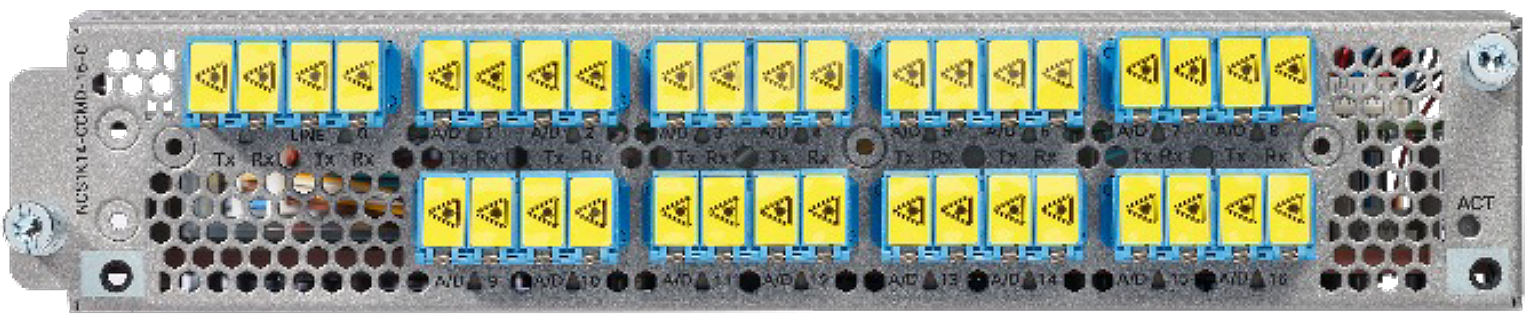
NCS 1014 16-Port Coherent Colorless Multiplexer Demultiplexer Module—C-Band
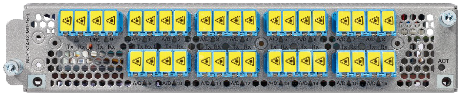
NCS 1014 16-Port Coherent Colorless Multiplexer Demultiplexer Module—L-Band
The CCMD line card supports low transmit power ZR+ coherent interfaces to generic line card coherent interfaces, which can be from Bright ZR+ or embedded line ports. This allows providers to deploy interfaces based on their network reach requirements, from metro to long haul, with a simple colorless add/drop architecture.
The CCMD line card supports 16 add/drop ports for TXPs and a composite port that feeds into the ROADM add/drop port. More and more networks are looking for higher degree support, which will limit the number of add/drop ports. The CCMD line card provides 64 channels with just 4 line cards in C-band and 4 line cards in L-band.
The Cisco® IOS XR operating system software that runs on NCS 1010 and NCS 1014 provides a rich suite of automation features that include zero-touch provisioning (ZTP), OpenConfig Yang models with Netconf and gNMI, streaming telemetry, and gNOI support. NCS 1010 is equipped with automated end-to-end turn-up of the network, which includes the embedded control loops within and between the ROADM nodes in the network.
Deployment architecture of NCS 1010 and NCS 1014 CCMD in a C- and L-band node:
NCS 1010 is a 3 RU chassis unit that can be deployed in C-/L-band OLT or ILA configuration. NCS 1014 is a 2 RU chassis consisting of 4 line card slots that can be equipped with transponder/muxponder or CCMD optical line cards. The below picture highlights the node architecture of a colorless directional add/drop architecture for a 2-degree node with C- and L-band support.
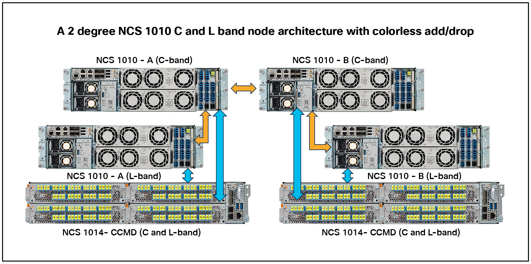
A 2-degree NCS 1010 C- and L-band node architecture with colorless add/drop
The following table lists out the specifications of the components of the NCS 1014 CCMD line card.
Table 1. Specifications of the CCMD line card
| Parameter |
Details |
| Line card support |
NCS 1014 |
| Number of slots |
1 slot |
| Power(typical) |
70 Watts |
Table 2. General details of the line card
| CCMD-C band |
Specifications |
| Channel grid |
64 channels, 75 GHz, spaced |
| Central wavelength - Channel 64 |
191.375 GHz (1566.52 nm) |
| Central wavelength - Channel 1 |
196.100 GHz (1528.77 nm) |
| EDFA operating frequency range |
From 191.250 GHz to 196.200 GHz |
Table 3. CCMD-C Add EDFA Gain range 1
| Parameter |
Condition |
Min |
Typ |
Max |
Unit |
| Per-channel input power range |
At CH-RX port |
-7.0 |
4.0 |
9.0 |
dBm |
| Total input power range |
After multiplexer |
-21.0 |
|
7 |
dBm |
| Total input power range |
At channel Rx port |
-7.0 |
|
21.0 |
dBm |
| Maximum total output power |
|
|
|
18.2 |
dBm |
| Output power shut-off threshold |
|
|
|
18.5 |
dBm |
| Signal output power range |
Full channel load—see power mask |
|
|
18.0 |
dBm |
| Single channel—see power mask |
0 |
|
6.0 |
dBm |
|
| Nominal gain |
With 0 dB tilt |
2 |
dB |
||
| Gain range |
With tilt uncontrolled |
-3.0 |
|
7.0 |
dB |
| Noise figure at nominal gain |
G = 2 dB |
|
|
5.7 |
dB |
| Noise figure at minimum gain |
G = -3 dB |
|
|
6.7 |
dB |
| Noise figure at maximum gain |
G = 7 dB |
|
|
5.4 |
dB |
| VOA attenuation range |
|
0 |
15 |
dB |
|
| DEG-TX to MON-TX relative attenuation |
|
18 |
20 |
22 |
dB |
| Directivity (optical path loss) |
Isolation at EDFA add output |
40 |
|
|
dB |
| Amplifier tilt coefficient |
Moving @ 1dB step from maximum flat gain |
|
|
0.25 |
dB/THz |
Table 4. CCMD-C Add EDFA Gain range 2
| Parameter |
Condition |
Min |
Typ |
Max |
Unit |
| Per-channel input power range |
At CH-RX port |
-22.0 |
-11.0 |
-6.0 |
dBm |
| Total input power range |
After multiplexer |
-36.0 |
|
-8 |
dBm |
| Total input power range |
At channel Rx port |
-22.0 |
|
6.0 |
dBm |
| Maximum total output power |
|
|
|
18.2 |
dBm |
| Output power shut-off threshold |
|
|
|
18.5 |
dBm |
| Signal output power range |
Full channel load—see power mask |
|
18.0 |
dBm |
|
| Single channel—see power mask |
0 |
|
6.0 |
dBm |
|
| Nominal gain |
With 0 dB tilt |
17 |
dB |
||
| Gain range |
With tilt uncontrolled |
12.0 |
22.0 |
dB |
|
| Noise figure at nominal gain |
G = 17 dB |
|
|
5 |
dB |
| Noise figure at minimum gain |
G = 12 dB |
|
|
5.4 |
dB |
| Noise figure at maximum gain |
G = 22 dB |
|
|
5 |
dB |
| VOA attenuation range |
|
0 |
|
15 |
dB |
| DEG-TX to MON-TX relative attenuation |
|
18 |
20 |
22 |
dB |
| Directivity (optical path loss) |
Isolation at EDFA add output |
40 |
dB |
||
| Amplifier tilt coefficient |
Moving @ 1dB step from maximum flat gain |
0.25 |
dB/THz |
Table 5. CCMD-C Drop EDFA
| Parameter |
Condition |
Min |
Typ |
Max |
Unit |
| Per-channel input power range |
At DEG-RX port |
-19.0 |
-8.0 |
-3.0 |
dBm |
| Total input power range |
At DEG-RX port |
-19.0 |
9 |
dBm |
|
| Maximum total output power |
9.2 |
dBm |
|||
| Output power shut-off threshold |
9.5 |
dBm |
|||
| Signal output power range |
Full channel load—see power mask |
9.0 |
dBm |
||
| Single channel—see power mask |
-9 |
-3.0 |
dBm |
||
| Nominal gain |
With 0 dB tilt |
5 |
dB |
||
| Gain range |
With tilt uncontrolled |
0.0 |
10.0 |
dB |
|
| Noise figure at nominal gain |
G = 5 dB |
|
5.9 |
dB |
|
| Noise figure at minimum gain |
G = 0 dB |
|
6.8 |
dB |
|
| Noise figure at maximum gain |
G = 10 dB |
|
5.9 |
dB |
|
| TP-C to MON-RX relative attenuation |
|
18 |
20 |
22 |
dB |
| VOA attenuation range |
|
0 |
15 |
dB |
|
| Directivity (optical path loss) |
Isolation at EDFA drop output |
40 |
dB |
||
| Amplifier tilt coefficient |
Moving @ 1dB step from maximum flat gain |
0.25 |
dB/THz |
| CCMD-L band |
Specifications |
| Channel grid |
64 channels, 75 GHz, spaced |
| Central wavelength - Channel 64 |
186'125 GHz (1610.7 nm) |
| Central wavelength - Channel 1 |
190'850 GHz (1570.83 nm) |
| EDFA operating frequency range |
From 186'025 GHz to 191'000 GHz |
Table 6. CCMD-L Add EDFA Gain range 1
| Parameter |
Condition |
Min |
Typ |
Max |
Unit |
| Per-channel input power range |
At CH-RX port |
-7.0 |
4.0 |
9.0 |
dBm |
| Total input power range |
After multiplexer |
-21.0 |
7 |
dBm |
|
| Total input power range |
At channel Rx port |
-7.0 |
21.0 |
dBm |
|
| Maximum total output power |
18.2 |
dBm |
|||
| Output power shut-off threshold |
18.5 |
dBm |
|||
| Signal output power range |
Full channel load—see power mask |
18.0 |
dBm |
||
| Single channel—see power mask |
0 |
6.0 |
dBm |
||
| Nominal gain |
With 0 dB tilt |
2 |
dB |
||
| Gain range |
With tilt uncontrolled |
-3.0 |
7.0 |
dB |
|
| Noise figure at nominal gain |
G = 2 dB |
6.4 |
dB |
||
| Noise figure at minimum gain |
G = -3 dB |
7.5 |
dB |
||
| Noise figure at maximum gain |
G = 7 dB |
5.9 |
dB |
||
| VOA attenuation range |
0 |
15 |
dB |
||
| DEG-TX to MON-TX relative attenuation |
18 |
20 |
22 |
dB |
|
| Directivity (optical path loss) |
Isolation at EDFA add output |
40 |
dB |
||
| Amplifier tilt coefficient |
Moving @ 1dB step from maximum flat gain |
0.25 |
dB/THz |
Table 7. CCMD-L Add EDFA Gain range 2
| Parameter |
Condition |
Min |
Typ |
Max |
Unit |
| Per-channel input power range |
At CH-RX port |
-22.0 |
-11.0 |
-6.0 |
dBm |
| Total input power range |
After multiplexer |
-36.0 |
-8 |
dBm |
|
| Total input power range |
At channel Rx port |
-22.0 |
6.0 |
dBm |
|
| Maximum total output power |
18.2 |
dBm |
|||
| Output power shut-off threshold |
18.5 |
dBm |
|||
| Signal output power range |
Full channel load—see power mask |
18.0 |
dBm |
||
| Single channel—see power mask |
0 |
6.0 |
dBm |
||
| Nominal gain |
With 0 dB tilt |
17 |
dB |
||
| Gain range |
With tilt uncontrolled |
12.0 |
22.0 |
dB |
|
| Noise figure at nominal gain |
G = 17 dB |
5.8 |
dB |
||
| Noise figure at minimum gain |
G = 12 dB |
5.9 |
dB |
||
| Noise figure at maximum gain |
G = 22 dB |
5.8 |
dB |
||
| VOA attenuation range |
0 |
15 |
dB |
||
| DEG-TX to MON-TX relative attenuation |
18 |
20 |
22 |
dB |
|
| Directivity (optical path loss) |
Isolation at EDFA add output |
40 |
dB |
||
| Amplifier tilt coefficient |
Moving @ 1dB step from maximum flat gain |
0.25 |
dB/THz |
Table 8. CCMD-L Drop EDFA
| Parameter |
Condition |
Min |
Typ |
Max |
Unit |
| Per-channel input power range |
At DEG-RX port |
-19.0 |
-8.0 |
-3.0 |
dBm |
| Total input power range |
At DEG-RX port |
-19.0 |
9 |
dBm |
|
| Maximum total output power |
9.2 |
dBm |
|||
| Output power shut-off threshold |
9.5 |
dBm |
|||
| Signal output power range |
Full channel load—see power mask |
9.0 |
dBm |
||
| Single channel—see power mask |
-9 |
-3.0 |
dBm |
||
| Nominal gain |
With 0 dB tilt |
5 |
dB |
||
| Gain range |
With tilt uncontrolled |
0.0 |
10.0 |
dB |
|
| Noise figure at nominal gain |
G = 5 dB |
7.4 |
dB |
||
| Noise figure at minimum gain |
G = 0 dB |
8.6 |
dB |
||
| Noise figure at maximum gain |
G = 10 dB |
6.9 |
dB |
||
| TP-C to MON-RX relative attenuation |
18 |
20 |
22 |
dB |
|
| VOA attenuation range |
0 |
15 |
dB |
||
| Directivity (optical path loss) |
Isolation at EDFA drop output |
40 |
dB |
||
| Amplifier tilt coefficient |
Moving @ 1dB step from maximum flat gain |
0.25 |
dB/THz |
Table 9. List of orderable PIDs
| Product ID |
Product description |
| NCS1K14-CCMD-16-C= |
NCS 1000 16-port Colorless Direct attach LC with EDFA C-band |
| NCS1K14-CCMD-16-L= |
NCS 1000 16-port Colorless Direct attach LC with EDFA L-band |
| ESS-CCMD-RTU= |
NCS 1014 CCMD16 Essentials RTU |
| ESS-CCMD-SIA3= |
NCS 1014 CCMD16 Essentials SIA for 3 years |
Information about Cisco’s Environmental, Social, and Governance (ESG) initiatives and performance is provided in Cisco’s CSR and sustainability reporting.
Table 10. Cisco environmental sustainability information
| Sustainability topic |
Reference |
|
| General |
Information on product-material-content laws and regulations |
|
| Information on electronic waste laws and regulations, including our products, batteries, and packaging |
||
| Information on product takeback and reuse program |
||
| Sustainability inquiries |
Contact: csr_inquiries@cisco.com |
|
| Material |
Product packaging weight and materials |
Contact: environment@cisco.com |
Product warranty terms and other information applicable to Cisco products are available at www.cisco.com/go/warranty.
Services from Cisco and our certified partners can help you transform the WDM system setup experience and accelerate business innovation and growth. We have the depth and breadth of expertise to create a clear, replicable, optimized coherent transport footprint across technologies. Planning and design services align technology with business goals and can increase the accuracy, speed, and efficiency of your deployment. Technical services can help you improve operational efficiency, save money, and mitigate risk. Optimization services are designed to continuously improve performance and help your team succeed with new technologies. For more information, please visit www.cisco.com/go/services.
Flexible payment solutions to help you achieve your objectives
Cisco Capital makes it easier to get the right technology to achieve your objectives, enable business transformation and help you stay competitive. We can help you reduce the total cost of ownership, conserve capital, and accelerate growth. In more than 100 countries, our flexible payment solutions can help you acquire hardware, software, services and complementary third-party equipment in easy, predictable payments. Learn more.
Add: www.cisco.com/go/ron
NCS 1000 datasheets: https://www.cisco.com/c/en/us/products/optical-networking/network-convergence-system-1000-series/datasheet-listing.html.