Achieve Optimal Network Throughput on the Cisco UCS Virtual Interface Card 1457 White Paper
Available Languages
Bias-Free Language
The documentation set for this product strives to use bias-free language. For the purposes of this documentation set, bias-free is defined as language that does not imply discrimination based on age, disability, gender, racial identity, ethnic identity, sexual orientation, socioeconomic status, and intersectionality. Exceptions may be present in the documentation due to language that is hardcoded in the user interfaces of the product software, language used based on RFP documentation, or language that is used by a referenced third-party product. Learn more about how Cisco is using Inclusive Language.
November 2018
Executive summary
This document describes the network I/O performance characteristics of the Cisco UCS® C240 M5 Rack Server using the Cisco UCS Virtual Interface Card (VIC) 1457, a 25-Gbps modular LAN-on-motherboard (mLOM) card based on the Cisco UCS VIC 1400 platform. The document discusses how to achieve optimal throughput on the Cisco UCS C240 M5 server in a variety of scenarios. The goal of this document is to demonstrate to customers that, with this Cisco Unified Computing System™ (Cisco UCS) server platform, they are investing in a enterprise-class server platform, and that they can achieve their desired level of network throughput by implementing the configuration presented here.
All performance data presented in this document was obtained using the iperf3 testing tool, with analysis based on the aggregate throughput of all the streams used to saturate the 25-Gbps links. The primary focus of this document is on how to achieve optimal throughput regardless of the environment.
Introduction
The Cisco Unified Computing System, or Cisco UCS, is a next-generation data center platform that unites computing, networking, storage access, and virtualization resources in a cohesive system designed to reduce total cost of ownership (TCO) and increase business agility. The system integrates a low-latency, lossless 10-, 25-, and 40-Gigabit Ethernet network fabric with enterpriseclass blade and rack x86-architecture servers. The system is an integrated, scalable, multichassis platform in which all resources participate in a unified management domain.
In fact, there are as many different network environments as there are customers, and no single solution can address them all. The Cisco UCS VIC 1457 is based on the most recent generation of the Cisco UCS VIC 1400 platform, which supports 25-Gbps throughput. This additional throughput option introduces a new set of challenges in a variety of situations. This document discusses how to meet those challenges and achieve optimal throughput.
Audience
This document assumes that readers have some familiarity with data center trends, server and storage technology, and the Cisco UCS product line. Readers should also have a working knowledge of Cisco Integrated Management Controller (IMC) web user interface, because this guide does not offer the start-to-finish configuration details usually found in more in-depth guides.
Network I/O challenges
Data center bandwidth requirements are growing at a fast rate, and with the latest-generation processors, high-performing nonvolatile memory express (NVMe) solid-state disks (SSDs), graphics processing units (GPUs), applications are demanding high bandwidth and faster I/O processing.
High-performance computing (HPC), distributed applications, artificial intelligence (AI), and machine learning need high-preforming networks and bandwidth. With the increased demand for bandwidth and faster I/O operations, with server network I/O exceeding 10 Gbps, a new set of challenges has arisen. To achieve the maximum desired throughput with higher bandwidth, you must address two factors in particular:
● Multiple application threads: As network I/O increases, higher CPU frequencies are needed to accommodate the I/O load. If a higher frequency is not possible, you will need more CPU cores to process all the requests. To address this requirement, you need an application that can take advantage of today’s multithreaded environments.
● Need for reduced request load: With network throughput of 25 Gbps, a tremendous amount of processing is required to service all the requests. You can reduce the load of those requests in two ways. The typical maximum transmission unit (MTU) value for most networks for many years has been 1500. However, by increasing the frame size so that the system uses an oversized or jumbo frame, you can reduce the processing load on the network adapter application-specific integrated circuit (ASIC) and the CPU in the system. Alternatively, you can increase the number of queues to achieve a more distributed method of receiving packets than with only a single queue.
Scope of this document
This document is limited to the discussion of testing and throughput measurement for the 25-Gbps link. All network performance testing was conducted between two Cisco UCS C240 M5 Rack Servers, and bandwidth was measured by connecting a 25-Gbps link from Cisco UCS VIC 1457 to a Cisco Nexus® switch. Default and optimal performance configuration and performance results were captured for MTU settings of both 1500 and 9000.
Note that the same settings as those used to achieve optimal throughput on the Cisco UCS C240 M5 server are applicable to other Cisco UCS C-Series Rack Servers and S-Series Storage Servers. However, test results for those servers are not presented in this document.
Infrastructure components
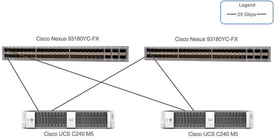
Figure 1 shows the Cisco UCS components used in the tests described in this document.
Hardware components
Cisco UCS C240 M5
The Cisco UCS C240 M5 Rack Server is a 2-socket, 2-rack-unit (2RU) server offering industry-leading performance and expandability. It supports a wide range of storage and I/O-intensive infrastructure workloads, from big data and analytics to collaboration. Cisco UCS C-Series Rack Servers can be deployed as standalone servers or as part of a Cisco UCS managed environment to take advantage of Cisco’s standards-based unified computing innovations that help reduce customers’ TCO and increase their business agility.
In response to ever-increasing computing and data-intensive real-time workloads, the enterprise-class Cisco UCS C240 M5 server extends the capabilities of the Cisco UCS portfolio in a 2RU form factor. It incorporates the Intel® Xeon® Scalable processors, supporting up to 20 percent more cores per socket, twice the memory capacity, and five times more NVMe PCI Express (PCIe) SSDs than the previous generation of servers. These improvements deliver significant performance and efficiency gains that will improve your application performance.
The C240 M5 delivers outstanding levels of storage expandability with exceptional performance, with:
● The latest Intel Xeon Scalable CPUs, with up to 28 cores per socket
● Up to 24 DDR4 DIMMs for improved performance
● Up to 26 hot-swappable small-form-factor (SFF) 2.5-inch drives, including 2 rear hot-swappable SFF drives (up to 10 support NVMe PCIe SSDs on the NVMe-optimized chassis version), or 12 large-form-factor (LFF) 3.5-inch drives plus 2 rear hot-swappable SFF drives
● Support for a 12-Gbps SAS modular RAID controller in a dedicated slot, leaving the remaining PCIe 3.0 slots available for other expansion cards
● mLOM slot that can be used to install a Cisco UCS VIC without consuming a PCIe slot, supporting dual 10, 25, or 40-Gbps network connectivity
● Dual embedded Intel x550 10GBASE-T LAN-on-motherboard (LOM) ports
● Modular M.2 or Secure Digital (SD) cards that can be used for boot
● C240 M5 servers can be deployed as standalone servers or in a Cisco UCS managed environment. When used in combination with Cisco UCS Manager, the C240 M5 brings the power and automation of unified computing to enterprise applications, including Cisco® SingleConnect technology, drastically reducing switching and cabling requirements.
Table 1 lists the specifications for the Cisco UCS C240 M5 Rack Server.
Table 1. Part numbers for Cisco UCS C220 M5 high-density SFF and LFF base rack server models
| Part number |
Description |
| Form factor |
2RU rack server |
| Processors |
Intel Xeon Scalable processors (1 or 2) |
| Memory |
24 DDR4 DIMM slots: 8, 16, 32, 64, and 128 GB and up to 2666 MHz |
| PCIe expansion |
6 PCIe 3.0 slots plus 1 dedicated 12-Gbps RAID controller slot and 1 dedicated mLOM slot |
| RAID controllers |
● Internal controllers: Cisco 12-Gbps Modular RAID Controller (PCIe 3.0) with 2- or 4-GB Flash-Backed Write Cache (FBWC), providing enterprise-class data protection for up to 26 SAS and SATA hard-disk drives (HDDs), SSDs, or NVMe PCIe SSDs; or Cisco 12-Gbps modular SAS host bus adapter (HBA)
● External controller: Cisco 12-Gbps 9400-8e SAS HBA
|
| Internal storage |
Backplane options:
● Up to 26 x 2.5-inch SAS and SATA HDDs and SSDs and up to 4 NVMe PCIe drives
● Up to 10 x 2.5-inch NVMe PCIe and 16 SAS and SATA HDDs and SSDs
● Up to 12 x 3.5-inch SAS and SATA HDDs and SSDs, and 2 rear 2.5-inch HDDs and SSDs and up to 4 NVMe PCIe drives
|
| Embedded network interface cards (NICs) |
Dual 10GBASE-T Intel x550 Ethernet ports |
| mLOM |
Dedicated mLOM slot that can flexibly accommodate 1-, 10-, 25-, 40-, and 100-Gbps adapters |
| Power supplies |
Hot-pluggable, redundant 770W AC, 1050W AC, 1050W DC, and 1600W AC |
| Other storage |
● Dual internal Cisco FlexFlash SD cards (32, 64, and 128 GB) for installing an operating system or hypervisor
● Support for RAID 0 mirroring between SD cards
● Dedicated Baseboard Management Controller (BMC) MicroSD card (32 GB) for server utilities
● Dual M.2 SATA SSD or NVMe
|
| Management |
|
| Rack options |
Cisco ball-bearing rail kit with optional reversible cable management farm |
| Hardware and software interoperability |
|
| Operating systems |
Microsoft Windows Server 2012, Microsoft Windows 2016, Red Hat Enterprise Linux (RHEL), SUSE Linux, or VMware vSphere |
Cisco UCS VIC 1457
The Cisco UCS VIC 1400 platform extends the network fabric directly to both servers and virtual machines so that a single
connectivity mechanism can be used to connect both physical and virtual servers with the same level of visibility and control. Cisco VICs provide complete programmability of the Cisco UCS I/O infrastructure, with the number and type of I/O interfaces configurable on demand with a zero-touch model.
Cisco VICs support Cisco SingleConnect technology, which provides an easy, intelligent, and efficient way to connect and manage computing in your data center. Cisco SingleConnect unifies LAN, SAN, and systems management into one simplified link for rack servers, blade servers, and virtual machines. This technology reduces the number of network adapters, cables, and switches needed and radically simplifies the network, reducing complexity. Cisco VICs can support 256 PCIe virtual devices, either virtual NICs (vNICs) or virtual HBAs (vHBAs), a high rate of I/O operations per second (IOPS), support for lossless Ethernet, and 10- and 40-Gbps connection to servers. The PCIe 3.0 x16 interface helps ensure optimal bandwidth to the host for network-intensive applications, with a redundant path to the fabric interconnect. Cisco VICs support NIC teaming, with fabric failover for increased reliability and availability. In addition, it provides a policy-based, stateless, agile server infrastructure for your data center.
The VIC 1400 series is designed exclusively for the M5 generation of Cisco UCS B-Series Blade Servers, C-Series Rack Servers, and S-Series Storage Servers. The adapters are capable of supporting 10-, 25, and 40-Gigabit Ethernet and Fibre Channel over Ethernet (FCoE). The VIC incorporates Cisco’s next-generation converged network adapter (CNA) technology and offers a comprehensive feature set, providing investment protection for future feature software releases. In addition, the VIC supports Cisco Data Center Virtual Machine Fabric Extender (VM-FEX) technology. This technology extends the Cisco UCS fabric interconnect ports to virtual machines, simplifying server virtualization deployment.
The Cisco UCS VIC 1457 (Figure 2) is a quad-port Small Form-Factor Pluggable (SFP28) mLOM card designed for the M5 generation of Cisco UCS C-Series Rack Servers. The card supports 10- and 25-Gbps Ethernet and FCoE. The card can present PCIe standards-compliant interfaces to the host, and these can be dynamically configured as either NICs or HBAs.
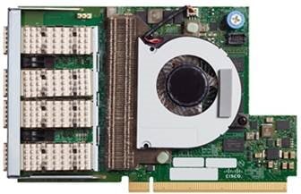
The Cisco UCS VIC 1400 platform provides the following features and benefits:
● Stateless and agile platform: The personality of the card is determined dynamically at boot time using the service profile associated with the server. The number, type (NIC or HBA), identity (MAC address and World Wide Name [WWN]), failover policy, bandwidth, and quality-of-service (QoS) policies of the PCIe interfaces are all determined using the service profile. The capability to define, create, and use interfaces on demand provides a stateless and agile server infrastructure.
● Network interface virtualization: Each PCIe interface created on the VIC is associated with an interface on the Cisco UCS fabric interconnect, providing complete network separation for each virtual cable between a PCIe device on the VIC and the interface on the fabric interconnect.
Cisco Nexus 93180YC-FX Switch
The Cisco Nexus 93180YC-FX Switch (Figure 3) is a 1RU switch with latency of less than 1 microsecond that supports 3.6 Tbps of bandwidth. The 48 downlink ports on the 93180YC-FX can be configured to work as 1-, 10-, or 25-Gbps Ethernet or FCoE ports or as 16- or 32-Gbps Fibre Channel ports, converging primary storage and computing servers, back-end storage, and policybased switching on the leaf node. The six uplink ports can be configured as 40- and 100-Gbps Ethernet or FCoE ports, offering flexible migration options. The switch has FC-FEC and RS-FEC enabled for 25-Gbps support.
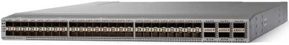
Table 2 lists the Cisco Nexus 9300-FX platform switch specifications.
Table 2. Cisco Nexus 9300-FX platform switch specifications
| Feature |
Cisco Nexus 93180YC-FX |
| Ports |
48 x 10/25-Gbps and 6 x 40/100-Gbps QSFP28 ports |
| Downlink supported speeds |
1/10/25-Gbps Ethernet 8/16/32-Gbps Fibre Channel |
| CPU |
6 cores |
| System memory |
64 GB |
| SSD drive |
128 GB |
| System buffer |
40 MB |
| Management ports |
1 RJ-45 port L1 and L2 ports are unused |
| USB ports |
1 |
| RS-232 serial ports |
1 |
| Power supplies (up to 2) |
500W AC, 930W DC, or 1200W HVAC/HVDC |
| Typical power (AC/DC) |
260W |
| Maximum power (AC/DC) |
425W |
| Input voltage (AC) |
100 to 240V |
| Input voltage (high-voltage AC [HVAC]) |
200 to 277V |
| Input voltage (DC) |
–48 to –60V |
| Input voltage (high-voltage DC [HVDC]) |
-240 to -380V |
| Frequency (AC) |
50 to 60 Hz |
| Fans |
4 |
| Airflow |
Port-side intake and exhaust |
| Physical dimensions (H x W x D) |
1.72 x 17.3 x 22.5 in. (4.4 x 43.9 x 57.1 cm) |
| Acoustics |
57 dBA at 40% fan speed, 68.9 dBA at 70% fan speed, and 77.4 dBA at 100% fan speed |
| RoHS compliance |
Yes |
| Mean time between failure (MTBF) |
238,470 hours |
Infrastructure configuration
Both Cisco UCS C240 M5 servers are configured in standalone mode (without using Cisco UCS Manager) and they are connected to a pair of Cisco Nexus 93180YC-FX Switches. Port 0 from each VIC is connected to port 1 of Cisco Nexus 93180YC-FX Switch A, and port 3 from each VIC is connected to port 1 of Cisco Nexus 93180YC-FX Switch B.
Table 3 and 4 shows the Hardware configuration and software version used for the testing
Table 3. Hardware configuration
| Component |
Configuration |
| 2 x Cisco UCS C240 M5 |
Each with 2 x Intel Xeon Scalable 6132 CPU 12 x 32 GB-2R-DDR4-2666MHz UCS VIC 1457 |
Table 4. Software version
| Component |
Version |
| CIMC |
4.0(1a) |
| Operating System |
Redhat 7.5 |
| enic driver |
3.0.107.37-492.52 |
| enic firmware |
5.0(1c) |
Three infrastructure configuration states were captured in the results:
● State 1: The first configuration state is as close to a default configuration as possible. The Cisco Nexus is configured with a standard 1500-MTU frame size. The adapter profiles on each Cisco UCS C240 M5 are configured with the default adapter profile using the Cisco IMC .
● State 2: The second configuration state applies jumbo frames to the vNIC and Cisco Nexus 93180YC-FX Switches.
● State 3: The final configuration state applies jumbo frames to the Cisco Nexus 93180YC-FX Switches, and an optimal adapter profile is applied to the network adapter on the vNIC.
Workload Characterization
The tools most commonly used to test network performance are iperf and iperf3. The classic tool is iperf. It has been in use for many years. The more recent version, iperf3, is fundamentally different from the original iperf. It benefits from a more compact code base and a more modern implementation. iperf3 supports multiple streams, and all streams used by its process are single threaded. It supports the tuning of various parameters related to timing, buffers, and protocols (TCP, User Datagram Protocol [UDP], and Stream Control Transmission Protocol [SCTP] with IPv4 and IPv6). For each test it reports the bandwidth, loss, and other parameters.
Test configuration
The results presented here represent all three states detailed in the preceding “Infrastructure configuration” section. Performance was measured using iperf3 to examine 25-Gbps throughput under a variety of conditions.
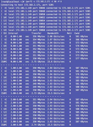
State 1: Default configuration
In this configuration, the default adapter profile is used with an MTU of 1500. The default configuration is shown here (Figure 4). With an MTU of 1500 and four parallel streams, the throughput was 21.7 Gbps, and with eight parallel streams, the throughput was 23.5 Gbps.
Performance results
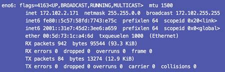
Figure 5 shows the interface configuration, and Figure 6 shows the configuration results.
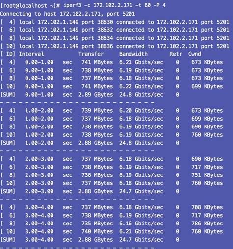
State 2: Jumbo frames enabled
The Ethernet adapter and Cisco Nexus 93180YC-FX Switches is configured with an MTU of 9000 with the default adapter profile. By using a more efficient transmission unit, the adapter can achieve a maximum throughput of 24.7 Gbps without the need to increase the number of queues and interrupts. If you can modify the existing network to support jumbo frames, or if jumbo frames are already set, this change is relatively simple to make. However, many customers cannot or do not want to accommodate an MTU of 9000 in their data center environments.
To configure jumbo frames in the vNICs, follow these steps:
1. From the Cisco UCS C240 M5 server’s IMC home screen, select the top-right button, which looks like this:

2. In the menu that appears, expand the Networking section and Adapter Card.
3. Select the vNICs tab.
4. In the left tree beneath the vNICs section, select the Ethernet adapter to be modified: most likely, eth0 or eth1, or both.
5. Set the MTU to 9000.
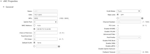
6. Save the changes and reboot the server to make the changes take effect.
Performance results
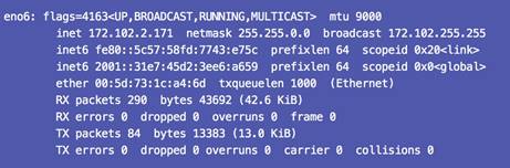
Figure 7 shows the interface configuration, and Figure 8 shows the results.

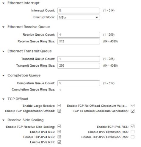
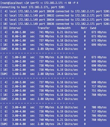
State 3: Jumbo frames enabled and optimal adapter profile applied
The Ethernet adapter (vNIC) is configured with an MTU of 9000 and an optimized adapter profile. By applying both settings, maximum throughput should be observed in almost all circumstances, which was observed in the tests to be 24.7 Gbps.
To apply an adapter profile, follow these steps:
1. From the Cisco UCS 240 M5 server’s IMC home screen, select the top-right button, which looks like this:
![]()
2. In the menu that appears, expand the Networking section and Adapter Card.
3. Select the vNICs tab.
4. In the left tree beneath the vNICs section, select the Ethernet adapter to be modified: most likely, eth0 or eth1, or both.
5. Set the MTU to 9000.
6. Provide a name for the Ethernet adapter policy. Change the following fields:
· Resources
o Transmit Queues: 8
o Ring Size: 4096
o Receive Queues: 8
o Ring Size: 4096
o Completion Queues: 16
o Interrupts: 32
· Options
o Receive Side Scaling (RSS): Enabled
7. Save the changes and reboot the server.
Performance results
Figure 9 shows the interface configuration, and Figure 10 shows the configuration results.
For more information
For additional information, see:
● https://www.cisco.com/c/en/us/products/switches/nexus-93180yc-fx-switch/index.html