A Comprehensive Guide to Kubernetes Networking with the Intersight Kubernetes Service White paper
Available Languages
Bias-Free Language
The documentation set for this product strives to use bias-free language. For the purposes of this documentation set, bias-free is defined as language that does not imply discrimination based on age, disability, gender, racial identity, ethnic identity, sexual orientation, socioeconomic status, and intersectionality. Exceptions may be present in the documentation due to language that is hardcoded in the user interfaces of the product software, language used based on RFP documentation, or language that is used by a referenced third-party product. Learn more about how Cisco is using Inclusive Language.
Few open-source projects have been as widely and rapidly adopted as Kubernetes (K8s), the de facto container orchestration platform. With Kubernetes, development teams can deploy, manage, and scale their containerized applications with ease, making innovations more accessible to their continuous delivery pipelines.
Cisco Intersight™ Kubernetes Service (IKS) is a fully curated, lightweight container management platform for delivering multicloud production-grade upstream Kubernetes. It simplifies the process of provisioning, securing, scaling, and managing virtualized Kubernetes clusters by providing end-to-end automation, including the integration of networking, load balancers, native dashboards, and storage provider interfaces.
IKS builds a Kubernetes cluster using 100% upstream native K8s images and therefore provides the same networking as a K8s cluster built from the ground up. This document will cover the following concepts:
● Control plane and worker node addresses
● Pod addresses
● Cluster IP service addresses
● Load-balancer server addresses
● Kubernetes API server virtual IP address
To implement networking in each cluster, IKS uses the following components:
● CNI: Calico running in IPIP overlay mode
● L3/L4 load balancing: MetalLB running in Layer-2 mode (ARP)
● L7 ingress: NGINX
Explanation of the IKS cluster setup wizard
The IKS cluster setup wizard contains six steps. Configurations relating to cluster networking are found in steps 2, 3, and 4.
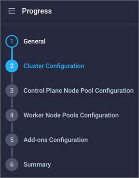
Steps in the IKS cluster creation wizard
If you have not yet built an IKS cluster in Cisco Intersight, please read through the IKS user guide below (this white paper is not designed to replace the user guide but to complement it with details on the networking configuration): https://intersight.com/help/saas/resources/intersight_kubernetes_service_user_guide
There is no network relation configuration on this page
Step 2 – Cluster Configuration
The cluster configuration page contains the following cluster-wide network related configurations:
● IP pool
● Load balancer count
● DNS server
● Pod network CIDR
● Service network CIDR
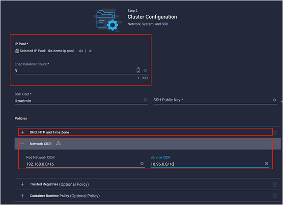
The relevant fields relating to the IKS cluster-wide networking configuration
IP pool
In the context of IKS, an IP pool is used to allocate Kubernetes API Server Virtual IP, node IP addresses, and Kubernetes LoadBalancer Service (MetalLB) IP addresses.
In this step, the IP pool is only used for the LoadBalancer Service addresses. This subnet must be routable and not overlap with an existing subnet in your environment.
IP pools support IPv4 addresses.
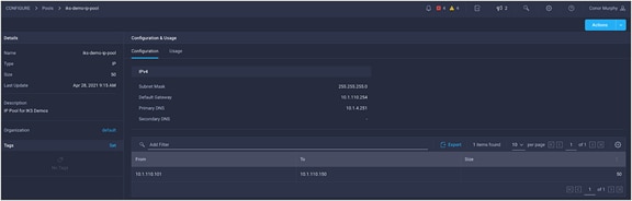
IKS IP pool. This example uses the same pool for the control plane, workers nodes, and LoadBalancer Service
Load balancer count
The load-balancer count field is used by the Kubernetes LoadBalancer Service. Use this field to specify how many IP addresses you wish to make available. These IP addresses are selected from your IP pool. When you create a new LoadBalancer service in your IKS cluster, MetalLB will assign an available IP address from the IP pool you have selected above. By default, IKS uses one IP address to provide external access to the cluster through the NGINX ingress.
DNS server
This field is used to configure the DNS server and suffix settings on the control plane and worker nodes. This will allow the nodes to perform DNS lookups. Kubernetes also provides DNS through the CoreDNS pods running on your cluster.
Pod network CIDR
Each control plane and worker node in your IKS cluster will receive its own internal subnet. This subnet is used to provide every pod an individual IP.
“By default, Calico uses an IPAM block size of 64 addresses – /26 for IPv4”
(Quoted from https://docs.projectcalico.org/networking/change-block-size)
The value that you enter in this field depends on the total number of nodes in the cluster (maximum size of control plane nodes + maximum size of worker nodes).
A minimum of 64 IP addresses must be available to each node for host assignment.
A valid size for a pod network is the maximum number of nodes in your cluster * 64. For example if you have if you have a cluster with one control node and three worker nodes, you would need a /24.
This field should not overlap with an existing subnet in your environment. Note that the pod network is non-routable outside of the cluster and can be reused for other clusters (as long as you don’t build a service mesh over both clusters).
Another common error is the following: if you are running an application in a pod that is trying to access an external resource that is also in the same subnet as the pod network, you will have conflicts because the pod traffic is routed to other pods.
Service network CIDR
Every time a Kubernetes service (ClusterIP, NodePort, or LoadBalancer) is created, a cluster IP is assigned. This is an internal, non-routable address that is used to forward traffic in a cluster. For the service network CIDR, the validation only needs to have a minimum of /24. Any bits above /24 will be rejected. For example, /25 through /30 would fail the validation since service network CIDRs require at least 254 hosts.
A valid prefix for a service network CIDR can be between /24 (254 hosts) through /8 (16,777,214 hosts). A CIDR prefix /25 or greater will fail.
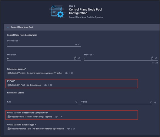
Step 3 – Control plane node pool configuration
The following configuration is networking related for the control plane nodes:
● IP pool
● Virtual machine infrastructure configuration
The configuration of the IKS control plane nodes
IP pool
As noted before, in the context of IKS, an IP pool is used to allocate node IP addresses and Kubernetes LoadBalancer Service (MetalLB) IP addresses.
In this step, the IP pool is used to assign IP addresses to the control plane nodes. You may need to have your control plane nodes on a different subnet from your LoadBalancer IPs, hence the need to select the IP pool twice. If you have a single routable subnet, you can select the same IP pool for both the LoadBalancer Service and your node IPs.
This subnet must be routable and not overlap with an existing subnet in your environment.
IP pools support IPv4 addresses.
Virtual machine infrastructure configuration
Since IKS currently runs in a virtualized environment, you need to provide the configuration to use for the VM settings when they are deployed (for example, VMware vSphere). Specifically relating to networking is the VM adapter interface that the control plane node will use (for example, the vSphere port group).
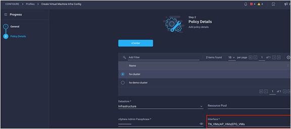
The configuration screen for the virtual machine infrastructure configuration
Step 4 – Worker node pools configurations
The following configuration is networking-related for the worker nodes:
● IP pool
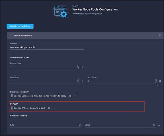
The configuration screen for a single worker node pool
IP pool
As noted before, in the context of IKS, an IP pool is used to allocate node IP addresses and Kubernetes LoadBalancer Service (MetalLB) IP addresses.
In this step, the IP pool is used to assign IP addresses to the worker nodes. You may need to have your worker nodes on a different subnet from your control plane nodes and LoadBalancer IPs, hence the need to select the IP pool a third time. If you have a single routable subnet, you can select the same IP pool for both the LoadBalancer Service and your node IPs (control plane and worker).
This subnet must be routable and not overlap with an existing subnet in your environment.
IP pools support IPv4 addresses.
Currently IKS UI only allows specifying one InfraConfigPolicy (that is, a virtual machine infrastructure configuration) for all the node pools. If you are specifying different subnets for each node pool, you need to ensure that they are routable through the network interface specified in the InfraConfigPolicy. The network interface was specified in Figure 5, above.
Alternatively, you can specify a different InfraConfigPolicy for each node pool that uses a different subnet/IP Pool. Note that this option is only currently available through the IKS API.
Kubernetes networking concepts
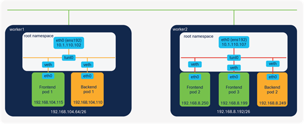
The following section will give you an introduction to Kubernetes networking in general. An IKS cluster with two worker nodes has been configured with the following networking settings for the purposes of this example:
● Node IP pool: 10.1.110.0/24 (externally routable)
● LoadBalancer IP pool: 10.1.110.0/24 (externally routable)
● Pod network CIDR: 192.168.0.0/16 (non-routable)
● Service network CIDR: 10.96.0.0/16 (non-routable)
The pod subnets of 192.168.104.64/26 and 192.168.8.192/26 have been assigned for worker1 and worker2, respectively.
Container-to-container communications
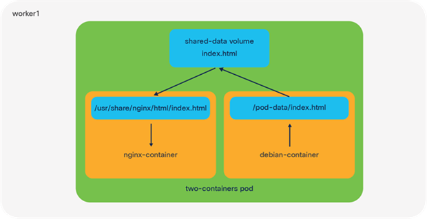
Shared volume communication
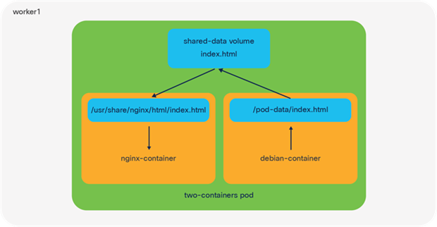
An illustration of a pod running two containers on an IKS node using a shared volume for networking
The smallest object you can deploy in Kubernetes is a pod; however, within each pod you may want to run multiple containers. A common use-case for this is a helper where a secondary container helps a primary container with tasks such as pushing and pulling data.
Container-to-container communication within a K8s pod uses either the shared file system or the local-host network interface.
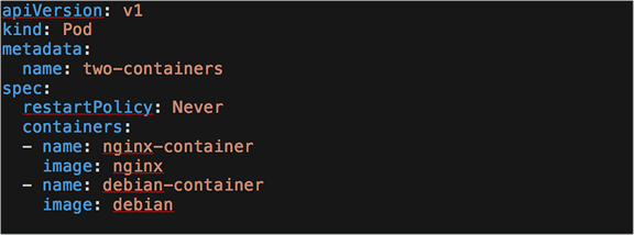
You can test this by using the K8s-provided example, two-container-pod, available through this link: https://k8s.io/examples/pods/two-container-pod.yaml
When you deploy this pod, you should see two containers, nginx-container and debian-container. When the shared volume method is used, Kubernetes will create a volume in the pod that is mapped to both containers. In the nginx-container, files from the shared volume will map to the /usr/share/nginx/html directory, while in the debian-container, files will map to the /pod-data directory.
When a file is updated (for example, index.html) from the Debian container, this change will also be reflected in the NGINX container, thereby providing a mechanism for a helper (Debian) to push and pull data to and from NGINX.
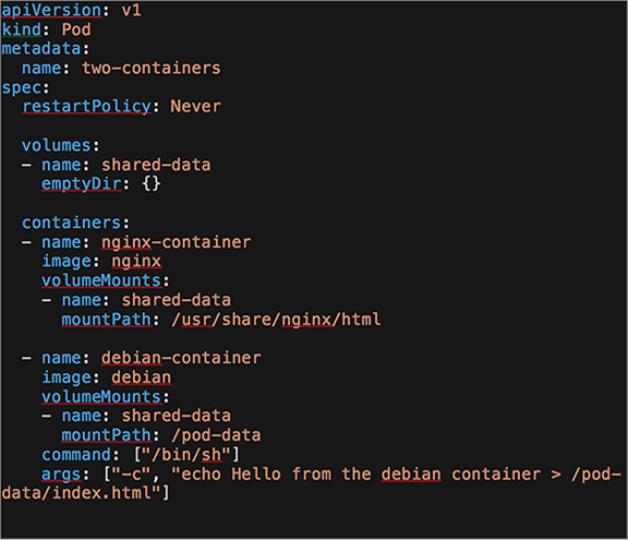
The YAML used to deploy the shared volume communication example
Local-host communication
An illustration of a pod running two containers on an IKS node using the local host for networking
The other method for multiple containers to communicate within a pod is through the local-host interface and the port number to which they’re listening.
You can test this again by using the K8s-provided example, two-container-pod, and modifying it slightly: https://k8s.io/examples/pods/two-container-pod.yaml
In this example NGINX is listening on port 80. If you run curl https://localhost from within the Debian container, you should see that the index.html page is served back from NGINX.
You can have multiple containers per pod in Kubernetes. This means that all containers in a pod share the same network namespace, IP address, and interfaces.
The YAML used to deploy the local-host communication example
Pod-to-pod communication on IKS
Important point: The following examples will use the Kubernetes guestbook application: https://raw.githubusercontent.com/kubernetes/examples/master/guestbook/all-in-one/guestbook-all-in-one.yaml
To follow along, deploy the Kubernetes guestbook to your IKS cluster.
kubectl apply -f https://raw.githubusercontent.com/kubernetes/examples/master/guestbook/all-in-one/guestbook-all-in-one.yaml
This application comprises two tiers, the front-end web server (Apache) and the back-end DB (Redis). Each tier has multiple pods deployed, with the pods running across two IKS worker nodes.
The IP addresses and subnets used in the subsequent examples
Network namespaces
Kubernetes and containers rely heavily on Linux namespaces to separate resources (processes, networking, mounts, users, etc.) on a machine.
“Namespaces are a feature of the Linux kernel that partitions kernel resources such that one set of processes sees one set of resources while another set of processes sees a different set of resources. . . .
“Network namespaces virtualize the network stack. Each network interface (physical or virtual) is present in exactly 1 namespace and can be moved between namespaces.
Each namespace will have a private set of IP addresses, its own routing table, socket listing, connection tracking table, firewall, and other network-related resources.”
(Quoted from https://en.wikipedia.org/wiki/Linux_namespaces.)
If you come from a networking background, the easiest way to think of a namespace is as functioning like a VRF; in Kubernetes each pod receives its own networking namespace (VRF).
Additionally, each Kubernetes node has a default or root networking namespace (VRF) that contains the external interface (for example, ens192) of the Kubernetes node.
When a pod is deployed Kubernetes first creates the pause container. This container runs a constant loop and allows for the networking namespace, and other resources used by all containers in a pod, to be available.
You can view the pause containers by SSHing into one of the Kubernetes nodes and running sudo docker ps -a | grep pause
Important point: Linux namespaces are different from Kubernetes namespaces. All mentions in this post are referring to the Linux network namespace.
Virtual cables and virtual Ethernet (veth) pairs
Within each pod exists an interface (for example, eth0). This interface allows connectivity outside the pods network namespace and into the root network namespace.
In the physical world, you might connect two interfaces together with a cable, for example, between a server and a switch. Kubernetes pods and nodes also have two connected interfaces. One side (for example, the eth0 interface) resides in the pod and the other side (for example, the virtual Ethernet interface) exists in the root namespace of the Kubernetes node.
Instead of a physical cable, these two interfaces are connected by a virtual cable. This is known as a virtual ethernet (veth) device pair and allows connectivity outside of the pods. See Figure 11, above, for an illustration.
Connectivity between veths
The connection from the virtual Ethernet (veth) interfaces to other pods and the external world is determined by the CNI plugin. For example, it may be a tunneled interface or a bridged interface.
Important point: Kubernetes does not manage the configuration of the pod-to-pod networking itself; rather, it outsources this configuration to another application, the Container Networking Interface (CNI) plugin.
“A CNI plugin is responsible for inserting a network interface into the container network namespace (e.g. one end of a veth pair) and making any necessary changes on the host (e.g. attaching the other end of the veth into a bridge). It should then assign the IP to the interface and setup the routes consistent with the IP Address Management section by invoking appropriate IPAM plugin.”
(Quoted from https://github.com/containernetworking/cni/blob/master/SPEC.md#overview-1)
Other popular plugins include Calico, Flannel, and Contiv, with each implementing the network connectivity in their own way.
Although the methods of implementing networking connectivity may differ between CNI plugins, every one of them must abide by the following requirements that Kubernetes imposes for pod-to-pod communications:
● Pods on a node can communicate with all pods on all nodes without NAT.
● Agents on a node (for example, system daemons, kubelets) can communicate with all pods on that node.
● Pods in the host network of a node can communicate with all pods on all nodes without NAT.
(Quoted from https://kubernetes.io/docs/concepts/cluster-administration/networking)
Important point: NAT is still used to provide connectivity such as source NAT on egress from pod to an external network, or destination NAT, on ingress from the internet into a pod.
The CNI plugin model
A CNI plugin is in fact an executable file that runs on each node and is located in the /opt/cni/bin directory. Kubernetes runs this file and passes it the basic configuration details, which can be found in /etc/cni/net.d.
IKS uses the Calico IP-IP encapsulation method to provide connectivity between pods. It is responsible for setting up the routing and the interfaces and assigning IP addresses to each pod.
The main components that Calico uses to configure IKS networking on each node are the Felix agent and BIRD.
Felix agent
The Felix agent is the heart of Calico networking. Felix’s primary job is to program routes and ACLs on a workload host to provide desired connectivity to and from workloads on the host.
Felix also programs interface information to the kernel for outgoing endpoint traffic. Felix instructs the host to respond to ARPs for workloads with the MAC address of the host.
(Information from https://docs.projectcalico.org/reference/architecture/overview#felix)
BIRD
The BIRD Internet Routing Daemon (BIRD) gets routed from Felix and distributes these routes to BGP peers on the network for inter-host routing.
When Felix inserts routes into the Linux kernel FIB, the BGP client distributes them to other nodes in the deployment.
(Information from https://docs.projectcalico.org/reference/architecture/overview#bird)
In the context of IKS, the BGP peers are the control plane and worker nodes. BIRD runs on each node within the calico-node pods in the kube-system namespace.
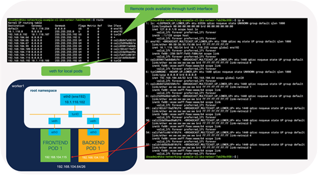
The interfaces and routes configured on the worker1 node
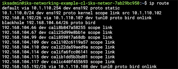
The routing table on worker1 showing the routes to worker2 (192.168.8.192/26) installed by BIRD
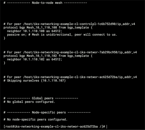
Output from /etc/calico/confd/config/bird.cfg in one of the calico-node pods showing the BGP configuration which was automatically created by BIRD
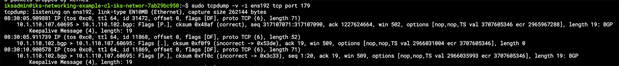
Output from tcpdump showing the BGP keepalive messages between the control plane and worker nodess
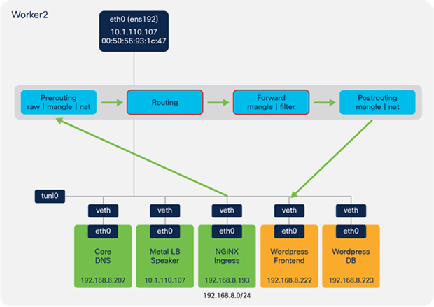
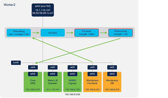
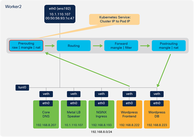
As per Figure 12, the IKS cluster contains a number of interfaces that have been created:
ens192 is the interface for external connectivity outside of the node. In the following example it has an address in the 10.1.110.0/24 subnet, which is routable in our environment. This is the subnet that was configured for the IP pool in the IKS cluster setup.
tunl0 is the interface that provides the IPIP encapsulation for remote nodes.
calixxxxx are the virtual ethernet interfaces that exist in the root namespace.
Remember, from before, that the veth interface connects to the eth interface in a pod.
Important point: As mentioned earlier, IKS implements Calico configured for IP-IP encapsulation. This is the reason for the tunneled interface (tunl0). A Kubernetes cluster with a different CNI plugin may have different interfaces, such as docker0, flannel0, or cbr0.
You’ll note in the routing table that Calico has inserted some routes. The default routes direct traffic out the external interface (ens192).
The following output is from the worker1 routing table on the example IKS cluster. This worker node has been assigned the subnet 192.168.104.64/26 for pods. As you can see, any pods on this worker are accessible through the veth interface, starting with calixxxxx.
Any time traffic is sent from a pod on worker1 to a pod on worker2, it is sent to the tunl0 interface.
If pod-to-pod communication takes place on the same node, it will send packets to the veth interfaces.
Traffic between pods on different worker nodes is sent to the tunl0 interface, which will encapsulate the packets with an outer IP packet. The source and destination IP addresses for the outer packet are the external, routable addresses (10.1.110.x subnet in this example).
You can confirm the encapsulation is taking place by capturing packets from the external interface (ens192 in the example). As shown in Figure 16 below, when traffic is sent from one Frontend Pod to another Frontend Pod, the inner packets are encapsulated in an outer packet containing the external source and destination addresses of the ens192 interfaces (10.1.110.102 and 10.1.110.107).
Since the 10.1.110.0/24 subnet is routable, the packets are sent upstream and find their way from worker1 to worker2. Arriving at worker 2, they are decapsulated and sent onto the local veth interface connecting to the Frontend Pod 2.
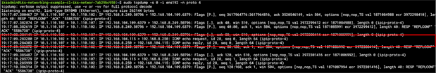
Confirmation of IP-IP encapsulation for packets sent directly from pods running on different hosts.
Kubernetes Services – tracking pods and providing external access
Although pod-to-pod communication takes place using IP in IP encapsulation, that’s only part of the implementation. It is not realistic that pods will communicate directly; for example, multiple pods may all perform the same function, as is the case of the guestbook application.
The guestbook has multiple frontend pods storing and retrieving messages from multiple backend database pods.
● Should each frontend pod only ever talk to one backend pod?
● If not, should each frontend pod have to keep its own list of which backend pods are available?
● If the pod subnets are internal to the nodes only and not-routable, how can the application be accessed from an external network
All of these points are addressed through the use of Kubernetes Services. Services are a native concept to Kubernetes, meaning they do not rely on an external plugin as is the case with the CNI for the pod and routing configuration
There are three primary services available:
● ClusterIP
● NodePort
● LoadBalancer
Kubernetes Services help with the following:
● Keeping track of pods
● Providing internal access from one pod (for example, frontend) to another (for example, backend)
● Providing L3/L4 connectivity from an external client (for example, a web browser) to a pod (for example, frontend)
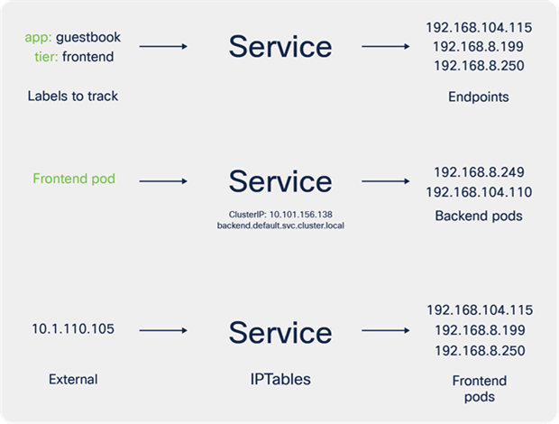
Labels, selectors, and endpoints
Labels and selectors are very important concepts in Kubernetes and are relevant to how a Kubernetes service tracks endpoints.
“Labels are key/value pairs that are attached to objects, such as pods [and] are intended to be used to specify identifying attributes of objects that are meaningful and relevant to users. Unlike names and UIDs, labels do not provide uniqueness. In general, we expect many objects to carry the same label(s).”
“Via a label selector, the client/user can identify a set of objects.”
(Quoted from https://kubernetes.io/docs/concepts/overview/working-with-objects/labels/)
Keeping track of pods
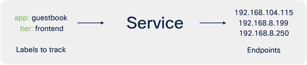
To demonstrate Kubernetes services on IKS, have a look at the deployment file for the guestbook application frontend pods.
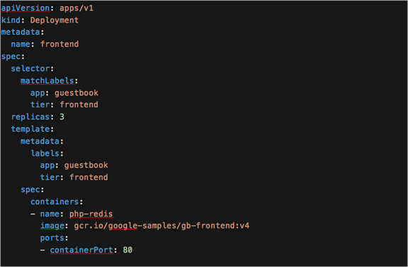
YAML definition for the guestbook frontend deployment
There are two labels, app: guestbook and tier: frontend, associated to the frontend pods that are deployed. These pods will receive an IP address from the range 192.168.x.x that we specified in the IKS cluster creation wizard (pod network CIDR).
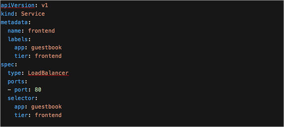
Now look at the service description for the frontend pods. There is one service definition for each deployment (frontend and backend in this example).
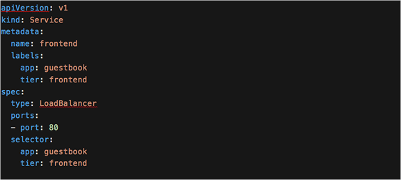
YAML definition for the guestbook frontend service
In this YAML the service has a selector that uses the same keys/values (app: guestbook and tier: frontend) as are configured in the deployment.
When a service is created, Kubernetes will track the IP addresses assigned to any of the pods that use the labels in the selector field. Any new pods created will automatically be tracked by Kubernetes.
As you scale up a deployment (potentially 100s or 1000s of pods deployed), Kubernetes will keep track of the internal pod endpoint IP addresses (192.168.x.x in this example).
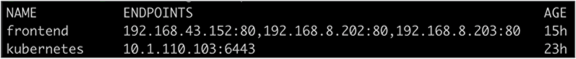
You can use the command, kubectl describe service <the-service-name>, to view the service type, the labels Kubernetes is tracking, and the pod endpoints that have those same labels.
Providing internal access from one pod (for example, frontend) to another (for example, backend)
If you look at the pods or processes running on the Kubernetes nodes, you won’t find one named “Kubernetes Service.” As per the Kubernetes documentation,
“A service is an abstraction which defines a logical set of Pods and a policy by which to access them.”
(Quoted from https://kubernetes.io/docs/concepts/services-networking/service/.)
While a Kubernetes Service is a logical concept, under the covers a pod called kube-proxy is running on each node to implements these rules.
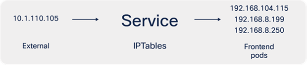
The kube-proxy pod watches the Kubernetes control plane for changes. Every time a new service is created, it will configure IPTables rules on the control plane and worker nodes. These rules redirect traffic from the ClusterIP (see below for details) to the IP address of the pod (192.168.x.x in the example).
Netfilter, IPTables, and connection tracking (Conntrack)
IPTables and connection tracking play a large part in the forwarding of traffic in an IKS cluster. Although you may only ever need to define Kubernetes resources such as a service or ingress, understanding how the rules are implemented can help in some scenarios, for example, when troubleshooting.
“IPTables is a user-space utility program that allows a system administrator to configure the IP packet filter rules of the Linux kernel firewall, implemented as different Netfilter modules.”
(Quoted from https://en.wikipedia.org/wiki/Iptables.)
“The connection tracking system stores information about the state of a connection in a memory structure that contains the source and destination IP addresses, port number pairs, protocol types, state, and timeout. With this extra information, we can define more intelligent filtering policies.”
(Quoted from https://people.netfilter.org/pablo/docs/login.pdf.)
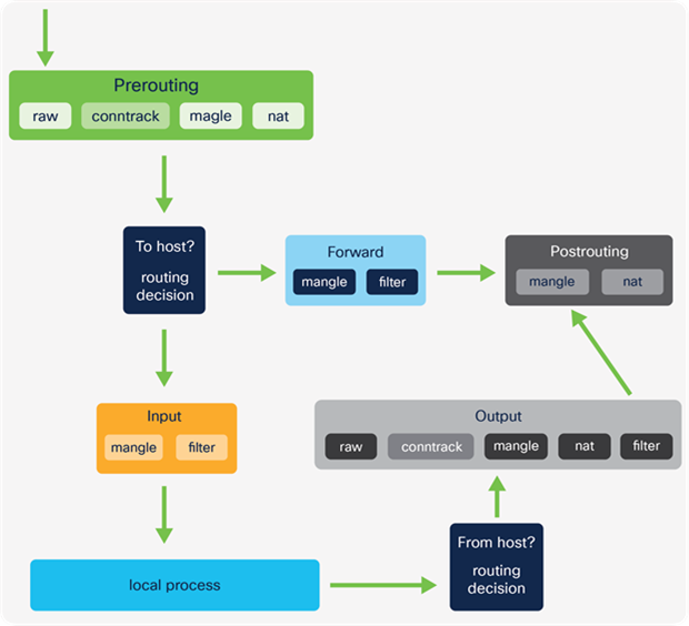
IPTables comprises tables with various purposes. The tables contain chains of rules that dictate how to treat each packet. There are four main tables and five predefined chains (see details below). Custom chains can also be created. This is shown later in more detail.
At a high level, a packet traverses the set of rules in each chain, and if a match is found, the packet can either jump to another chain in the same table, or a verdict of accept, reject, or drop may affect the packet. If the current rule does not match the patch, it continues to the next rule.
IPTables tables and chains example
IPTables tables and chains example
IPTables tables and chains example
IPTables tables and chains example
IPTables tables and chains
Tables
● Raw
◦ This table is used to store rules that mark packets to opt out of connection tracking.
● Mangle
◦ These rules alter IP headers such as TTL and can also mark packets for further processing.
● NAT
◦ Rules that implement SNAT and DNAT functions
● Filter
◦ matches packets and takes action, for example, accept or drop
Chains
● Prerouting
◦ First chain used after traffic is received by an interface
● Forward
◦ Used for any packet that has been routed and is not destined for a local host process
● Postrouting
◦ Rules that apply to packets after a routing decision has been made and it’s determined they are not for local host processes
● Input
◦ Packets destined for the host (that is, the Kubernetes node)
◦ ip route show table local
● Output
◦ Packets sent from the host
When manipulating and forwarding traffic in IKS, the Prerouting, Forward, and Postrouting chains are primarily used.
Viewing Kubernetes Services
Run the following command to view the Kubernetes services for your deployment.
kubectl get services
Kubernetes ClusterIP
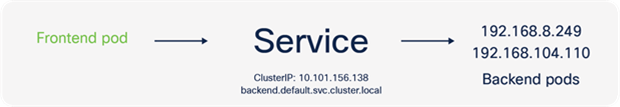
The Kubernetes ClusterIP is an IP address assigned to a service that is internal to the Kubernetes cluster and only reachable from within the cluster. This subnet was entered in the service network CIDR field as part of the IKS cluster creation wizard.
Every time a new Kubernetes services is created a ClusterIP is assigned.
Continuing with the IKS guestbook example, each frontend and backend service has been configured with a ClusterIP (for example, 10.96.127.227). The kube-proxy pod configures IPTables rules to redirect any traffic destined to these ClusterIPs to one of the available pods for that service.
Services and Network Address Translation (NAT)
Network Address Translation (NAT) is used provide outbound connectivity from a pod to an external network, or internal connectivity from a network to a pod.
● Pod to external network
The pod subnets in IKS are internal to a cluster (192.168.x.x in the example). When a packet exits a Kubernetes control plane or worker node from a pod, it requires an externally routable source address. This is implemented using source NAT (SNAT). SNAT replaces the source IP on a packet.
IKS uses the IP address of the node from which the packet egresses as the source IP of the packet.
● External network to pod
Since the pod subnet (192.168.x.x in the example) is internal to the IKS cluster, packets coming from a subnet that is not the pod network require an external IP address on which they can reach the pod. Destination NAT (DNAT) changes the destination IP address from external address (for example, a node) to the internal pod IP address. Packets from an external network to a pod also include return traffic (for example, packets in a flow between frontend and backend pods). To handle return traffic, connection tracking is implemented to maintain state and ensure that the return traffic reaches the correct destination pod.
To recap, Kubernetes Services are translated into IPTables rules and provide connectivity between pods as well as inbound and outbound traffic.
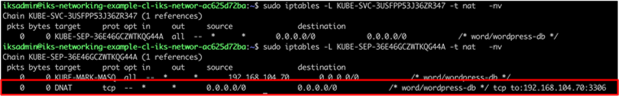
You can view the NAT configuration by viewing the IPTables rules.
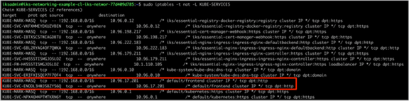
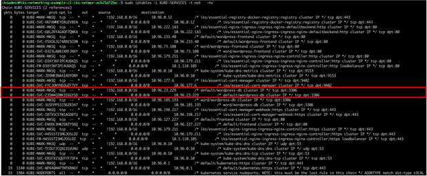
IPTables rules implemented on worker node 1 for the guestbook frontend service
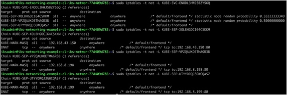
IPTables rules implemented on worker node 1 for the guestbook frontend service. Three frontend pods exist; therefore, three rules have been created. The pod selected to receive the traffic is chosen at random.
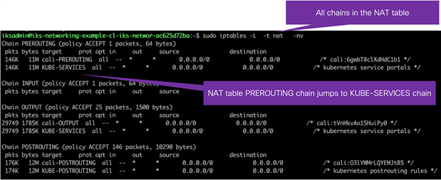
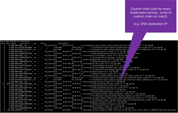
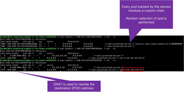
● KUBE-SERVICES is the entry point for service packets. What it does is to match the destination IP:port and dispatch the packet to the corresponding KUBE-SVC-* chain.
● KUBE-SVC-* chain acts as a load balancer, and distributes the packet to KUBE-SEP-* chain equally. Every KUBE-SVC-* has the same number of KUBE-SEP-* chains as the number of endpoints behind it.
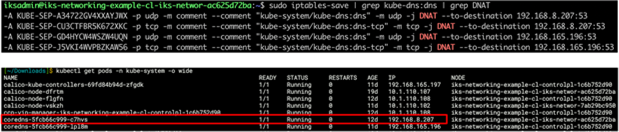
● KUBE-SEP-* chain represents a Service EndPoint. It simply does DNAT, replacing service IP:port with pod's endpoint IP:Port.
(Quoted from https://kubernetes.io/blog/2019/03/29/kube-proxy-subtleties-debugging-an-intermittent-connection-reset/.)
DNS Services
Not only does Kubernetes assign each service a ClusterIP address, but DNS records are also automatically configured. IKS will deploy CoreDNS pods to provide internal DNS resolution for your pods and services.
Important point: The DNS server address configured as part of the IKS cluster creation wizard applies to the IKS control plane and worker nodes.
As per the following Kubernetes documentation,
“Kubernetes DNS schedules a DNS Pod and Service on the cluster and configures the kubelets to tell individual containers to use the DNS Service’s IP to resolve DNS names.”
“Every Service defined in the cluster . . . is assigned a DNS name. By default, a client Pod’s DNS search list will include the Pod’s own namespace and the cluster’s default domain.”
(Quoted from https://kubernetes.io/docs/concepts/services-networking/dns-pod-service/.)
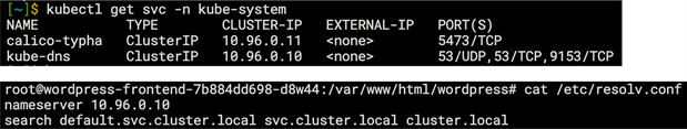
When the backend service is deployed as part of the guestbook application, not only is there an associated ClusterIP address, but there is also a DNS record created, backend.default.svc.cluster.local. “Default” in this case being the name of the Kubernetes namespace in which the backend pods run. Since every pod is configured to automatically use Kubernetes DNS, the address above should resolve correctly.
In the guestbook example the frontend pods can reference backend.default.svc.cluster.local in the application code. This will resolve to the ClusterIP address for the backend service which is then translated to one of the IP addresses of these pods (192.168.x.x).
Providing external access to the cluster – NodePort service
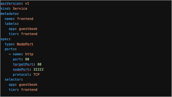
YAML definition for the guestbook frontend service when using a NodePort
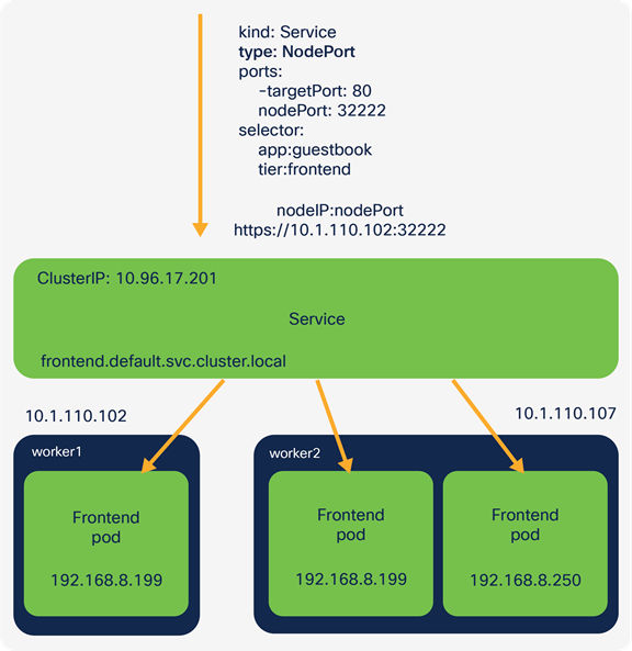
The Kubernetes Service configurations include a field, type, which describes the type of service. This can be a type: clusterIP (as previously seen), type: NodePort, or type: LoadBalancer.
The NodePort service is configured by specifying a port (default is between 30000-32767) to which the external traffic is sent. A target port on which the application is listening must also be configured. For example, the guestbook application listens on port 80.
When this service has been configured, an external client can access the pods (for this service) using the IP address of any IKS cluster nodes (externally routable 10.1.110.0 in the example) and the configured NodePort.
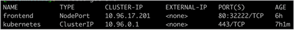
The output from running the kubectl get services command
Using the guestbook example, you can use https://<worker-node-ip>:32222 and have access to the guestbook application through a browser.
Kubernetes will forward this traffic to one of the available pods on the specified target port (in this case, one of the frontend pods, port 80).
Accessing the application through the IP address of a node and the configured NodePort
Under the hood, Kubernetes has configured IPTables rules to translate the traffic from the worker node IP address: NodePort to the destination pod IP address:port.
Providing external access to the cluster – LoadBalancer service
YAML definition for the guestbook frontend service when using a LoadBalancer
The Kubernetes LoadBalancer service exposes pods externally using either a public cloud provider or an on-premises load balancer.
(Information from https://kubernetes.io/docs/concepts/services-networking/service/.)
MetalLB is automatically deployed into each IKS cluster and provides L3/L4 load balancing services.
As per the following document,
“MetalLB is a load-balancer implementation for bare metal Kubernetes clusters, using standard routing protocols.”
(Information from https://metallb.universe.tf/.)
The LoadBalancer service relies upon an address selected from a pool that has been configured. This was the load balancer count field in the IKS cluster creation wizard.
When a Kubernetes LoadBalancer Service is configured, MetalLB will allocate the next available IP address from the pool of addresses provided. Any traffic destined to the IP is handled by MetalLB and forwarded onto the correct pods.
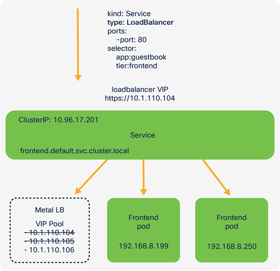
Accessing the application through an IP address assigned by the MetalLB LoadBalancer
IKS uses MetalLB in Layer-2 mode (ARP/NDP).
As per the following document,
“Under the hood, MetalLB responds to ARP requests for IPv4 services, and NDP requests for IPv6. In layer 2 mode, all traffic for a service IP goes to one node. From there, kube-proxy spreads the traffic to all the service’s pods.”
(Quoted from https://metallb.universe.tf/concepts/layer2/.)
You can verify that MetalLB is assigning IPs correctly by looking at the logs of the MetalLB pods.
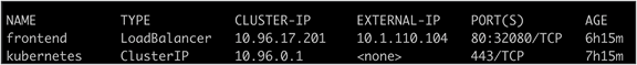
Output of the kubectl get services command showing the frontend service with a Loadbalancer external IP
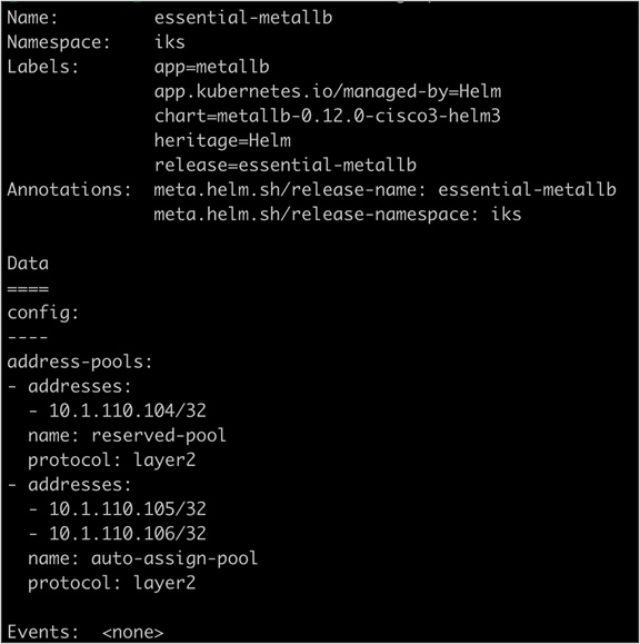
Output of the kubectl describe configmap essential-metallb -n iks command showing the configuration of MetalLB and available addresses
Kubernetes Ingress: rule-based routing
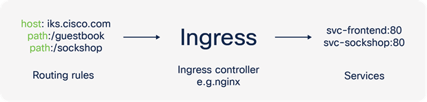
A Kubernetes Ingress exposes HTTP and HTTPS routes from outside the cluster to services within the cluster. Traffic routing is controlled by rules defined on the Ingress resource.
There are a number of benefits to using an ingress:
● Centralized SSL termination
● Rule-based routing
● Reduction in IP address usage
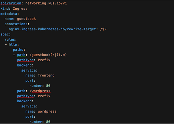
There are a number of ways to configure a Kubernetes Ingress. A fanout is used for this example. A fanout configuration routes traffic from a single IP address to more than one service.
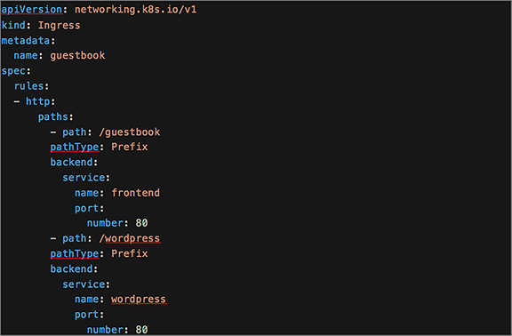
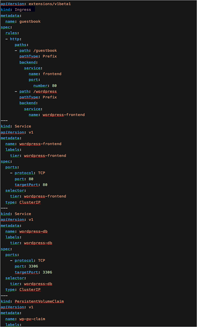
The YAML definition for a Kubernetes Ingress
Note in the YAML file above the set of rules defining two HTTP paths, one to a guestbook application and one to a different application called Wordpress.
Kubernetes Ingress controller
A Kubernetes Ingress itself does not provide the rule-based routing. Instead it relies on an ingress controller to perform this function.
There are many ingress controller options available. IKS automatically deploys an NGINX ingress controller to each Kubernetes cluster.
(Information from https://kubernetes.io/docs/concepts/services-networking/ingress-controllers/.)
On each IKS node you should see an nginx-ingress-controller-xxxxx pod running.
IKS will automatically create a LoadBalancer Service to direct external traffic to the nginx-ingress-controller-xxxxx pods. Hence the reason for requiring at least one IP address in the load-balancer count field (cluster creation wizard).
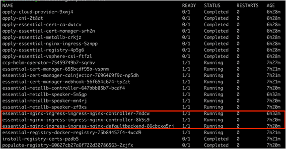
The output of the kubectl get pods -n iks command showing the NGINX ingress controllers deployed on each IKS node

The output of the kubectl get services -n iks command showing the NGINX ingress controller service (LoadBalancer)
Similar to how MetalLB works for Kubernetes Services, the NGINX controller will look for any changes to the Kubernetes Ingress definition. When a new ingress is configured, the NGINX configuration (nginx.conf in the nginx-ingress-controller-xxxxx pods) is updated with the new routing rules added to the ingress YAML file.
Each ingress controller also has options to provide annotations for custom configuration of the specific controller. For example, you can find the available NGINX annotations at the following link: https://kubernetes.github.io/ingress-nginx/user-guide/nginx-configuration/annotations/
Since the ingress controller is running in multiple pods, the LoadBalancer service provides direct external traffic to one of the available NGINX controller pods.
From there the NGINX controller will redirect based on the path, either to the guestbook frontend service or the Wordpress service. The services (IPTables rules) will in turn forward the traffic onto an available pod managed by the respective service.
Use cases for a Kubernetes Ingress
Additional to the routing rules previously described, a Kubernetes Ingress helps conserve IP addresses. When a service of type LoadBalancer is used, an externally routable address for each service configured must be assigned. While the addresses may be available on premises, in a public cloud environment there can often be a cost associated to each external IP address.
When using an ingress, a single external IP address can be assigned (for the ingress service). Each service behind the ingress can then use a ClusterIP. In this scenario the services are only accessible through the ingress and therefore don’t require a public IP address.
Kubernetes Ingress also provides a single ingress point for which all routing rules and TLS termination can be configured.
Ingress configuration when serving assets
Depending on the applications you’re deploying, you may run into some issues while serving content through a Kubernetes Ingress. For example, serving a webpage along with assets such as images, JS, and CSS files.
The following example will use the Kubernetes guestbook application (there is also a service named Wordpress configured in the ingress examples below; however, only the guestbook is used).
Here is the Kubernetes Ingress definition. In this example the filename is ingress.yaml.
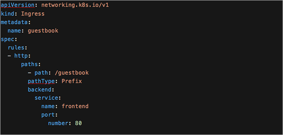
The YAML definition for a Kubernetes Ingress
The application is deployed by applying both files.
kubectl apply -f guestbook-all-in-one.yaml
kubectl apply -f ingress.yaml
Once running, the guestbook application should be available using the IP address of the ingress controller.
kubectl -n iks get svc essential-nginx-ingress-ingress-nginx-controller -o jsonpath='{.status.loadBalancer.ingress[0].ip}
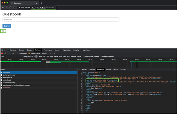
The guestbook application when working correctly
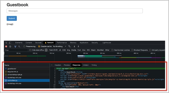
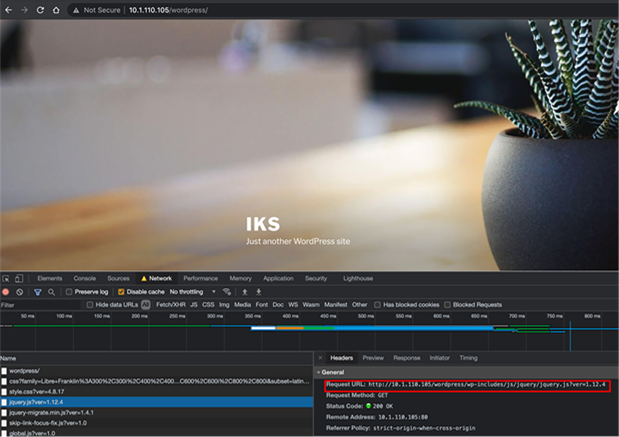
You can view the files accessed by the guestbook by looking at the developer tools in your browser.
Opening the developer tools console in a browser
Chrome: https://developer.chrome.com/docs/devtools/open/
Firefox: https://developer.mozilla.org/en-US/docs/Tools
The developer tools window when the guestbook application is working correctly
In the example, the path: / configuration in the ingress YAML file acts as a wildcard, therefore matching all assets that are required (index.html, controllers.js, guestbook.php).
Important point: In Kubernetes 1.18 there are ingress enhancements (exact and prefix keywords) to provide more granular control.
(Information from https://kubernetes.io/blog/2020/04/02/improvements-to-the-ingress-api-in-kubernetes-1.18/.)
Since there's a match, the controller will forward these to the associated service, frontend.
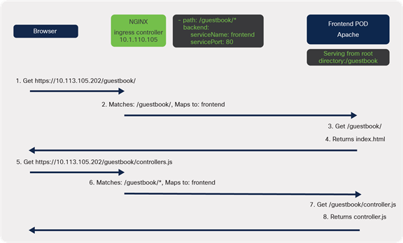
The frontend webserver, Apache, has been configured as default and is serving content from the root directory,/, so returns the requested files.
The connection flow when working correctly
Single ingress for multiple applications
You may run into issues when trying to use the same root path when deploying multiple applications on the same ingress.
In the following example, if the same path points to two different services there is no way to determine which one is correct.
The YAML definition for a Kubernetes Ingress with the same paths
To overcome this, each service can be accessed from a unique path.
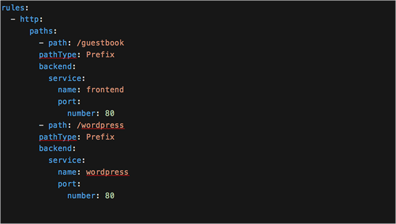
The YAML definition for a Kubernetes Ingress with differing paths
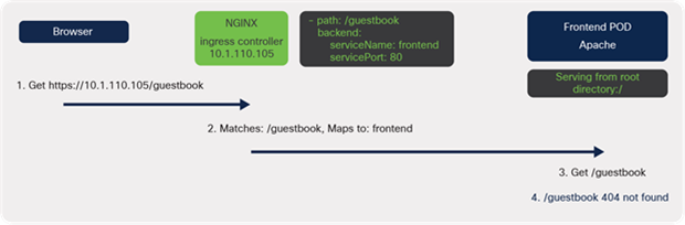
Now that a path has been configured, the application will need to be accessed via http://<ingress-controller-ip>/guestbook.
A 404 Page Not Found error should appear.
When traffic reaches the ingress controller, it matches path: /guestbook and is sent to the web server. The browser is trying to access files located in the /guestbook subdirectory; however, the web server is serving content from the root directory, /.
A diagram of the connectivity when serving content from the root directory
Rewriting the location
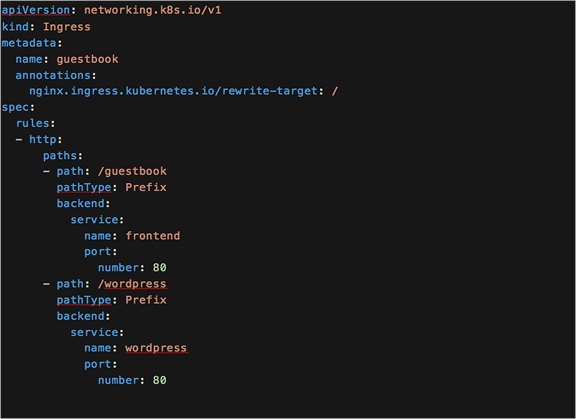
YAML definition for an updated Ingress that includes the rewrite target
Kubernetes Ingress annotations can be used to overcome this initial issue. Specifically, for IKS use the NGINX Ingress rewrite-target annotation.
(Information from https://kubernetes.github.io/ingress-nginx/examples/rewrite/.)
The annotations in the Kubernetes Ingress allow you to include custom configurations required for an ingress controller environment. In this example, a custom NGINX configuration is added to the nginx.conf file on the ingress controller pods automatically.
Important Point: The available annotations may differ depending on which ingress controller is used.
Using the rewrite-target annotation specifies the target URI where the traffic must be redirected.
In the example, the path, /guestbook, is matched. NGINX will then rewrite it to / before sending it to the web server. As it is now rewritten to the root directory, /, the index.html file is returned correctly, as was the case in the first scenario.
However, a problem still exists.
Within the index.html file is a reference to a few assets (CSS and JS files) that are used to build the guestbook. When the page loads it tries to download the required files, one of those being controller.js. Because it is rewriting to /, the index.html page is returned a second time.
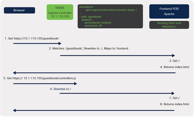
A diagram of the connectivity when serving content from the root directory and rewriting the path at the ingress
Output from the developer console showing the response returned
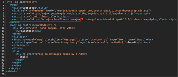
Source code for the guestbook index.html file
Here are some options to solve this problem.
Option 1: Serve this content from a different location
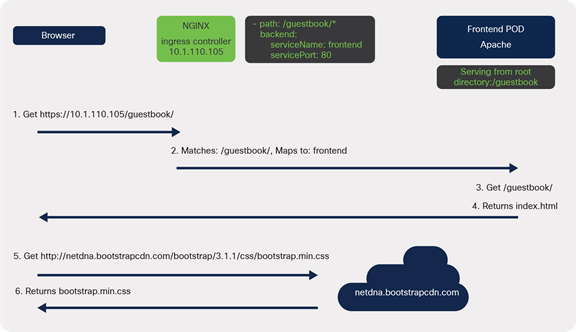
Communication flow when serving content from a different location
The first option is to separate the static content from the main HTML files and host them externally.
An example of this in the guestbook application is the bootstrap.min.css file. Bootstrap is a popular frontend open-source toolkit, is hosted on a Content Delivery Network (CDN), and is available for anyone to use.
When the page loads, the bootstrap CSS file is downloaded directly from the CDN. This means the ingress or web server rules are not used to serve this file.
A drawback of this approach is having to manage the files that are hosted somewhere else.
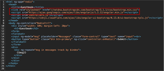
Source code for the guestbook index.html file showing the use of a CDN for the bootstrap CSS file
Option 2: Modify the Kubernetes Ingress to include a capture group
“In Version 0.22.0 and beyond, any substrings within the request URI that need to be passed to the rewritten path must explicitly be defined in a capture group.”
(Quoted from https://kubernetes.github.io/ingress-nginx/examples/rewrite/#rewrite-target)
The second option is to modify the Kubernetes Ingress to include the assets (e.g. controllers.js ) when rewriting the target. This is achieved through the use of a capture group. In Figure 49 there are two capture groups, defined by the parentheses, which contain regex to match text. In the example in Figure 49, any text matching the first capture group, (/|), can be accessed with $1. Any text matching the second capture group, (.*), can be accessed by referencing $2.
To serve the static assets (e.g. controllers.js), the path should be rewritten to include the text in the second capture group. The regular expression, (.*), used in this capture group will match any characters after /guestbook/, for example /guestbook/controllers.js
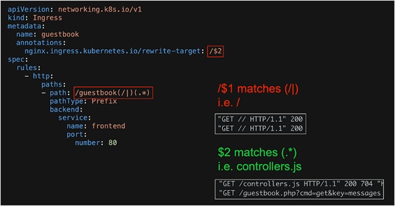
The modified Kubernetes Ingress which includes a capture group
Ingress YAML definition including the rewrite capture groups
Option 3: Change the Apache serving directory
A diagram of the communication when modifying the web server to serve from a subdirectory
A third option is to modify the configuration on the web server, in this case Apache.
From the testing performed so far it is evident that a subdirectory, /guestbook, is required. When this was configured the web server returned a 404. This was caused by Apache serving content from the root directory, /. It was not able to find the guestbook subdirectory files.
To solve this problem you must tell Apache to stop serving content from root, /, and instead make /guestbook the root directory.
In the apache2.conf configuration file you need to modify the DocumentRoot so it reads:
DocumentRoot /var/www/html/guestbook
On Ubuntu you should find apache2.conf in the /etc/apache2/ directory.
Update this file and remove the rewrite-target annotation from the ingress because it is no longer serving content from the root directory. Also move all the guestbook files (controllers.js, guestbook.php, index.html) to a new folder so the new path is /var/www/html/guestbook. Restart Apache if needed.
If everything has worked the guestbook application should be loaded successfully and all static assets loaded correctly.
Important point: Apache was used as the web server in the guestbook example.
You may need to modify different files depending on the web server you have deployed.
Output from guestbook when the ingress path is working correctly
Another example – Wordpress
In some cases you may not need to update the web server or code, for example if deploying a Wordpress site.
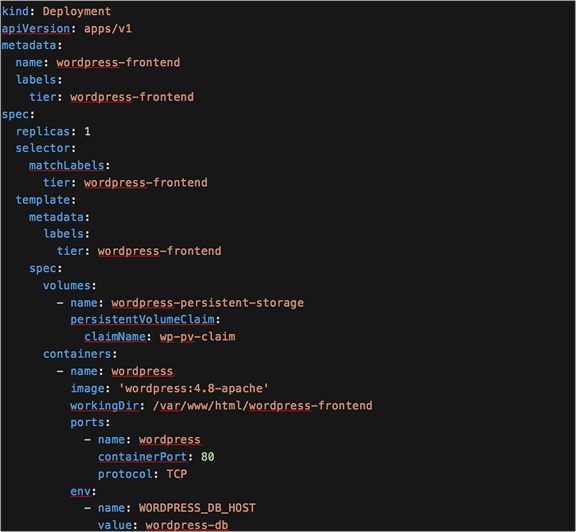
Wordpress is a popular opensource content management system that was originally created for blogging. It’s made up of a PHP frontend with a MySQL database. In this example it is deployed in Kubernetes as two pods, one frontend (Apache with PHP) and one DB (MySQL).
To configure Wordpress behind a Kubernetes Ingress you can change the working directory for the Wordpress frontend deployment. In Figure 53 below you can see that the workingDir is /var/www/html/wordpress
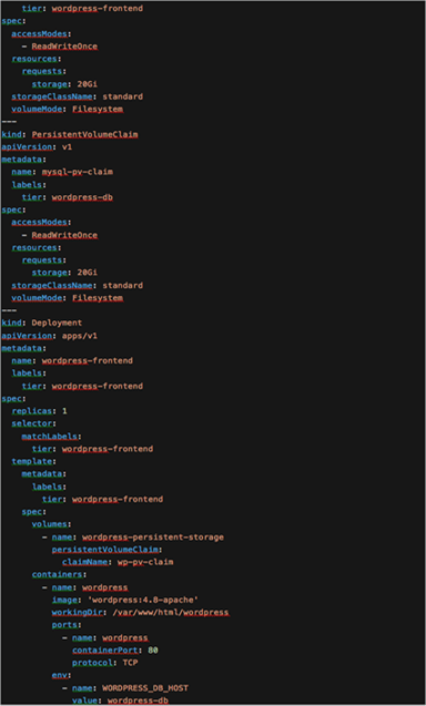
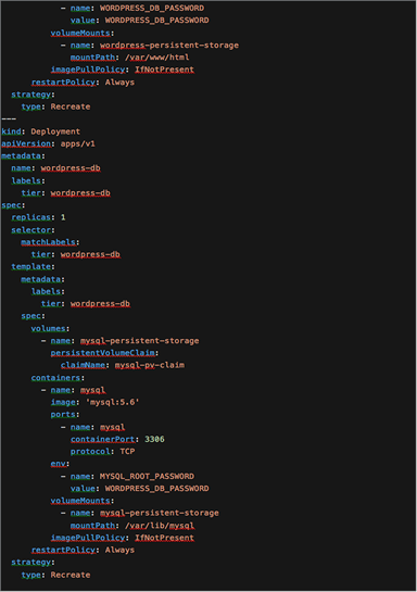
YAML for the all-in-one Wordpress deployment
When the configuration is applied, the deployment scripts will install Wordpress into the current working directory (/var/www/html/wordpress).
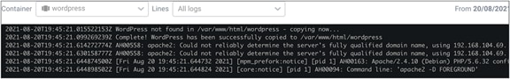
Log files from the initial Wordpress deployment showing the Wordpress files are copied to the new subdirectory
Developer tools output from the Wordpress deployment behind an ingress showing the Wordpress site is accessible from the subdirectory
Putting it all together – an end-to-end flow
This section will trace the packet flow using the Wordpress all-in-one deployment from Figure 53.
Important point: The following configuration and patterns have been used to capture **some** data flows for this example. This is not a complete output but aims to provide guidance on tracing flows.
● IPTables was configured to log to /var/log/messages
● The following IPTables logging rules were configured.
◦ The log prefix is used when printing the output table and contains the chain and table information. See Figure 56 below for an example.
#### HANDSHAKE ####
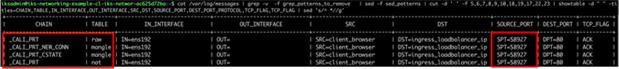
sudo iptables -t mangle -I cali-PREROUTING 1 -p tcp -m state --state NEW -j LOG --log-prefix "_CALI_PRT_NEW_CONN mangle " --log-level 1
sudo iptables -t raw -I cali-PREROUTING 1 -p tcp --tcp-flags SYN,ACK SYN,ACK -j LOG --log-prefix "_CALI_PRT_CONN_EST raw " --log-level 1
sudo iptables -t raw -I cali-PREROUTING 2 -p tcp --tcp-flags FIN,ACK FIN,ACK -j LOG --log-prefix "_CALI_PRT_CONN_CLOSED raw " --log-level 1
#### RAW ####
sudo iptables -t raw -I cali-PREROUTING 3 -j LOG --log-prefix "_CALI_PRT raw " --log-level 1
#### MANGLE ####
sudo iptables -t mangle -I cali-PREROUTING 2 -j LOG --log-prefix "_CALI_PRT_CSTATE mangle " --log-level 1
#### FILTER ####
sudo iptables -t filter -I cali-from-hep-forward 1 -j LOG --log-prefix "_CALI_FWD_TO_HEP filter " --log-level 1
sudo iptables -t filter -I cali-from-hep-forward 1 -j LOG --log-prefix "_CALI_FWD_FROM_HEP filter " --log-level 1
sudo iptables -t filter -I cali-to-wl-dispatch 1 -j LOG --log-prefix "_CALI_FWD_TO_POD filter " --log-level 1
sudo iptables -t filter -I cali-from-wl-dispatch 1 -j LOG --log-prefix "_CALI_FWD_FROM_POD filter " --log-level 1
sudo iptables -t filter -I cali-tw-cali11aba968e90 1 -j LOG --log-prefix "_CALI_FWD_AT_POD_WP filter " --log-level 1
sudo iptables -t filter -I cali-tw-cali545edbfd5b2 1 -j LOG --log-prefix "_CALI_FWD_AT_POD_DB filter " --log-level 1
sudo iptables -t filter -I cali-from-hep-forward 1 -j LOG --log-prefix "_CALI_INPUT filter " --log-level 1
sudo iptables -t filter -I cali-from-hep-forward 1 -j LOG --log-prefix "_CALI_OUTPUT filter " --log-level 1
sudo iptables -t filter -I KUBE-FORWARD 1 -j LOG --log-prefix "_KUBE_FORWARD_CSTATE filter " --log-level 1
#### NAT ####
sudo iptables -t nat -I cali-PREROUTING 1 -j LOG --log-prefix "_CALI_PRT nat " --log-level 1
sudo iptables -t nat -I KUBE-NODEPORTS 1 -j LOG --log-prefix "_KUBE_NODEPORTS_NGINX nat " --log-level 1
sudo iptables -t nat -I KUBE-SVC-D3XY3KFIPC4U6KQS 1 -j LOG --log-prefix "_KUBE_SVC_NGINX nat " --log-level 1
sudo iptables -t nat -I KUBE-SEP-AH3PTBOUGNT5BH3N 2 -j LOG --log-prefix "_KUBE_NGINX_WKR_1_DNAT nat " --log-level 1
sudo iptables -t nat -I KUBE-SEP-JKWKVBBQCO4U3ZLS 2 -j LOG --log-prefix "_KUBE_NGINX_WKR_2_DNAT nat " --log-level 1
sudo iptables -t nat -I KUBE-SVC-Y5XG6JG74RRE5O3W 1 -j LOG --log-prefix "_KUBE_SVC_WP_FRONTEND nat " --log-level 1
sudo iptables -t nat -I KUBE-SEP-QAOWPL7S7I7Y6Q3X 2 -j LOG --log-prefix "_KUBE_WP_FRNTEND_WKR_2_DNAT nat " --log-level 1
sudo iptables -t nat -I KUBE-SVC-235M4OZWKIE6GYSD 1 -j LOG --log-prefix "_KUBE_SVC_WP_DB nat " --log-level 1
sudo iptables -t nat -I KUBE-SEP-WAAL3DOSOAXDLALS 2 -j LOG --log-prefix "_KUBE_WP_DB_WKR_2_DNAT nat " --log-level 1
sudo iptables -t nat -I KUBE-SVC-TCOU7JCQXEZGVUNU 1 -j LOG --log-prefix "_KUBE_SVC_DNS nat " --log-level 1
sudo iptables -t nat -I KUBE-SEP-GD4HYCW4WSZW4UQN 2 -j LOG --log-prefix "_KUBE_DNS_CNTL_DNAT nat " --log-level 1
sudo iptables -t nat -I KUBE-SEP-A34722GV4XXAYJWX 2 -j LOG --log-prefix "_KUBE_DNS_WKR_2_DNAT nat " --log-level 1
sudo iptables -t nat -I cali-OUTPUT 1 -j LOG --log-prefix "_CALI_OUTPUT nat " --log-level 1
sudo iptables -t nat -I cali-nat-outgoing 1 -j LOG --log-prefix "_CALI_NAT_OUTGOING_NAT nat " --log-level 1
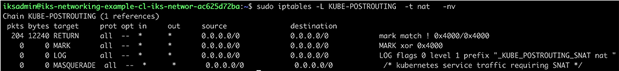
sudo iptables -t nat -I KUBE-POSTROUTING 3 -j LOG --log-prefix "_KUBE_POSTROUTING_NAT nat " --log-level 1
● A grep patterns file was created to filter the required output logs,
systemd\|rsyslogd\|kubelet\|named\|=6443\|sshd\|SRC=127.0.0.1\|192.168.104.67\|192.168.8.232\|192.168.8.228\|192.168.8.231\|192.168.8.195\|192.168.8.227\|DPT=10254\|DPT=8181\|DPT=8080\|SPT=22\|DPT=22\|SPT=443\|DPT=443\|SPT=179\|DPT=179\|SPT=123\|DPT=123
● A SED patterns file was used to convert the IP addresses into more relevant names,
s/MAC=.*SRC/SRC/g
s/10.1.0.89/client_browser/g
s/10.1.110.108/control_ens192/g
s/10.1.110.102/worker_1_ens192/g
s/10.1.110.107/worker_2_ens192/g
s/192.168.165.192/control_tunnel0/g
s/192.168.104.64/worker_1_tunnel0/g
s/192.168.8.192/worker_2_tunnel0/g
s/192.168.104.65/nginx_pod_worker_1/g
s/192.168.8.193/nginx_pod_worker_2/g
s/10.1.110.105/ingress_loadbalancer_ip/g
s/192.168.8.222/wordpress_frontend/g
s/192.168.8.223/wordpress_db/g
s/192.168.8.207/kube_dns/g
s/192.168.165.196/kube_dns/g
s/10.96.23.229/wordpress_db_svc/g
s/10.96.0.10/kube-dns-svc/g
s/10.96.179.211/nginx_svc_cluster_ip/g
s/cali7394c99cdd4/nginx_worker1_veth/g
s/cali21ac0ad37cb/nginx_worker2_veth/g
s/cali8d8a05feee4/coredns_worker_1_veth/g
s/cali148b7202262/coredns_worker_2_veth/g
s/cali11aba968e90/wordpress_frontend_veth/g
s/cali545edbfd5b2/wordpress_db_veth/g
● The output was cut into columns and added to a table to achieve the end result.
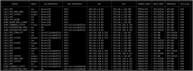
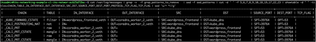
cat /var/log/messages | grep -v -f grep_patterns_to_remove | sed -f sed_patterns | cut -d ' ' -f 5,6,7,8,9,10,17,18,19,22 | showtable -d " " -titles=CHAIN,TABLE,IN_INTERFACE,OUT_INTERFACE,SRC,DST,PROTOCOL,SOURCE_PORT,DEST_PORT,TCP_FLAG | sed 's/^ *//g' | more
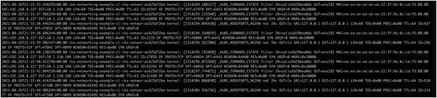
Example of /var/log/messages
Example of output without SED replacement
Example of output with SED replacement
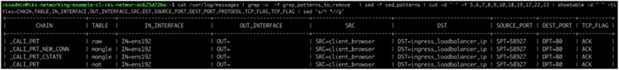
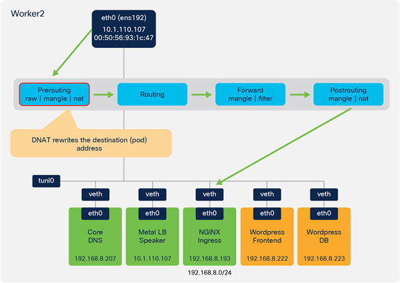
● Client browser connects to Wordpress (https://10.1.110.105/wordpress).
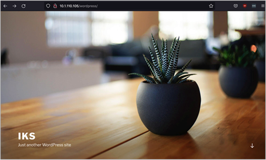
Accessing the Wordpress frontend
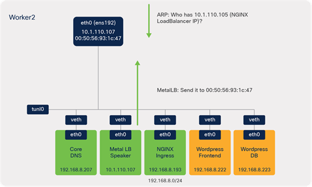
● ARP sends a request for IKS NGINX IKS LoadBalancer IP (10.1.110.105).
![]()
ARP request and response
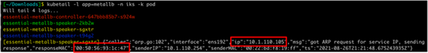
Output from the metallb logs

Output from the kubectl get svc -n iks command
● MetalLB speaker (worker 2) responds – send it to 00:50:56:93:1c:47 (MAC of ens192 on worker 2).
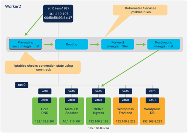
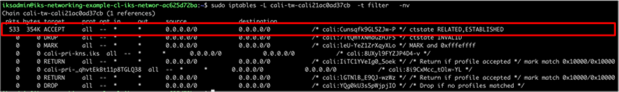
● The IPTables Raw, Mangle, and NAT tables of the Prerouting chain are used.
◦ Connection tracking is used to check the state as part of the Mangle table.
![]()
Client browser to NGINX Ingress – Prerouting chain
Logging from the client browser to NGINX Ingress – Prerouting chain
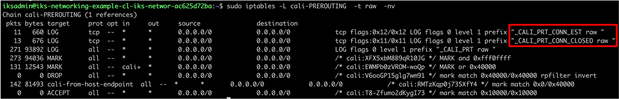
Logging from the client browser to NGINX Ingress – Prerouting chain
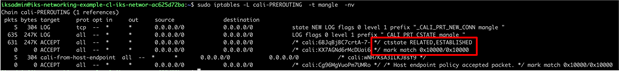
Logging from the client browser to NGINX Ingress showing connection tracking integration – Prerouting chain
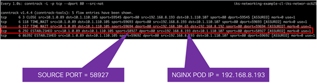
Connection tracking output
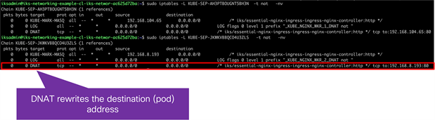
● DNAT is used to rewrite the destination (pod) address.
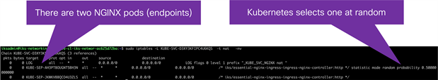
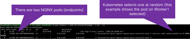
● Since there are two NGINX ingress pods (one on each worker node), Kubernetes selects one at random.
◦ In this example, the local ingress pod on worker 2 is selected.
![]()
Prerouting DNAT

Logging showing Prerouting DNAT
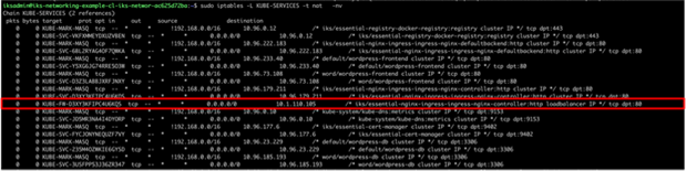
Output from IPTables showing the rule for NGINX
![]()
Output from IPTables showing the rule for NGINX
Output from IPTables showing the NGINX pods
Output from IPTables showing the DNAT rule for the NGINX pod
● A forwarding decision is made based on routing information. Since the NGINX destination pod is local, the traffic is dispatched to the relevant Calico veth interface on worker 2.
◦ The Calico IPTables rules accept the traffic destined to the pod.
![]()
Client browser to NGINX ingress – routing and forward

Logging from the client browser to NGINX Ingress – routing and forward chain
Output from calicoctl tool showing Kubernetes pod, node, and veth mapping
Output from routing table showing local veth interface
IPTables rules for Calico local veth interfaces
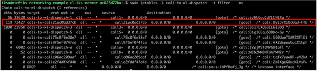
IPTables rules for Calico local veth interfaces
IPTables rules for Calico local veth interfaces
● Traffic traverses the NAT table in the Postrouting chain and sent to the veth interface on the NGINX worker 2 pod.
![]()

Postrouting to NGINX ingress

Logging showing NGINX Ingress – postrouting chain
![]()
IPTables rules showing the postrouting chain
IPTables rules showing the postrouting chain
● Traffic is sent from the NGINX pod to the Wordpress frontend pod based on the NGINX ingress configuration (stored within the nginx.conf file on the ingress controller pods).
![]()

NGINX ingress to Wordpress frontend
Logging showing NGINX ingress to Wordpress frontend – prerouting chain
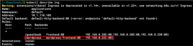
Output from kubectl describe ingress command
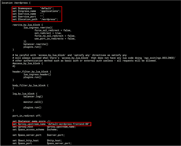
nginx.conf showing the wordpress ingress rules
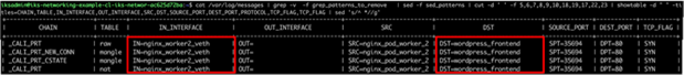
● Traffic is forwarded from the NGINX pod veth interface to the veth interface on the Wordpress frontend pod.
![]()
NGINX ingress to Wordpress frontend – routing and forward
![]()
Logging NGINX ingress to Wordpress frontend – routing and forward chains
● Traffic traverses the IPTables NAT table in the Postrouting chain to forward the traffic onto the Wordpress frontend veth interface.
![]()

NGINX ingress to Wordpress frontend – postrouting
![]()
Logging NGINX ingress to Wordpress frontend – postrouting chain
● The Wordpress frontend sends traffic to the Wordpress DB service.
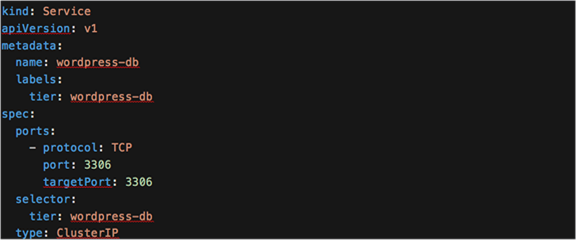
● The Wordpress frontend deployment has the DB host (WORDPRESS_DB_HOST) configured, pointing to the DB Kubernetes Service, wordpress-db
● The pod resolves the service name to the service IP address by sending the DNS query to a Kube-DNS pod.
YAML description of Wordpress frontend deployment and Wordpress DB service
![]()
Wordpress frontend to CoreDNS to resolve Wordpress DB service
Logging showing Wordpress frontend to CoreDNS to resolve Wordpress DB service – forward and postrouting chains
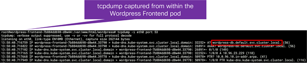
tcpdump from within the Wordpress frontend pod showing the DNS requests for the wordpress-db service
Output from within the Wordpress frontend pod showing the configured nameserver as the kube-dns service
● Traffic traverses the IPTables NAT table in the Prerouting chain.
![]()
Wordpress frontend to Wordpress DB - prerouting
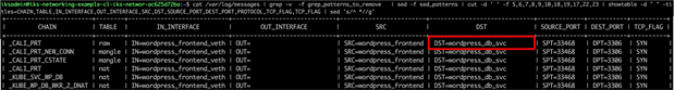
Logging the Wordpress frontend to Wordpress DB – prerouting chain
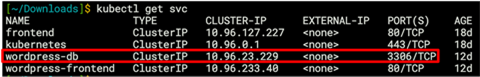
Output from the kubectl get service command showing the wordpress-db port
IPTables rules to direct traffic to the wordpress-db port
IPTables rules to direct traffic to the wordpress-db port
● Using the IPTables Filter and NAT tables in the Forward and Postrouting chains, the traffic is sent to the veth interface on the Wordpress DB pod.
![]()
Wordpress frontend to Wordpress DB – routing, forward, and postrouting
![]()
Logging from Wordpress frontend to Wordpress DB – routing, forward, and postrouting chains
![]()
Output from connection tracking
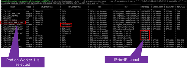
All the traffic in the example so far has been located on the same worker node. In many cases pods may be running across multiple nodes in the Kubernetes cluster. When this occurs, the traffic will leave one node and enter a second node where the workload is running. As previously described, IKS uses Calico for container networking and implements IP-IP tunneling.
Figure 106 provides an example of the forwarding behaviour when traffic is sent between Kubernetes nodes in IKS.
● In the example, the client traffic has reached Worker 2, based on the ARP response from MetalLB.
● There are two NGINX pods and, through the IPTables rules, it is determined that the NGINX pod on Worker 1 is used for the connection.
● Based on a route lookup, the traffic is sent to the tunl0 interface and encapsulated (IP in IP encapsulation).
● Traffic is sent out the ens192 interface to the NGINX pod on Worker 1.
![]()

Example flow showing tunnelled traffic from worker 2 to worker 1
Logging from IPTables showing showing traffic is directed to NGINX on worker 1
IPTables rules showing two NGINX pods
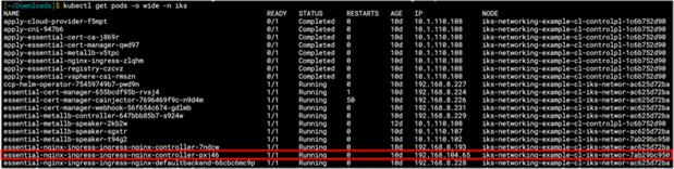
Output from kubectl get pods -o wide -n iks command showing the selected NGINX pod is running on worker 1
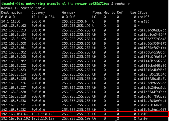
Output from the routing table on worker 2 indicating the traffic for worker 1 should use the tunl0 interface
Troubleshooting IKS networking connectivity
Output from the kubectl get pods -n iks command
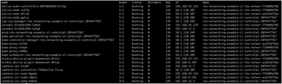
Output from the kubectl get pods -n kube-system command
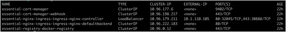
Output from the kubectl get services -n iks command

Output from the kubectl get services -n kube-system command
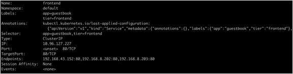
Output from the kubectl get describe service frontend command
![]()
Output from the kubectl get ingress command
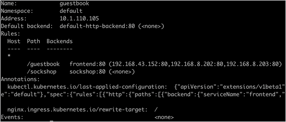
Output from the kubectl describe ingress guestbook command
Output from the kubectl get endpoints command