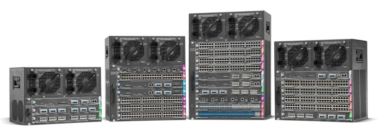
Cisco Catalyst 4500 Series Switches
| Product Type | Campus LAN Switches - Access |
|---|---|
| Status |
End of Sale
EOL Details
|
| Series Release Date | 17-SEP-2002 |
| End-of-Sale Date | 30-OCT-2020 |
| End-of-Support Date | 31-OCT-2025 |
| Diagram | Visio Stencil (4 MB .zip file) |
|
This product is supported by Cisco, but is no longer being sold. Consider switching to something new: The Cisco Catalyst 9400 Series Switches offer greater speed, performance and security. View the benefits of upgrading >
|
|


- US/Canada 800-553-2447
- Worldwide Support Phone Numbers
- All Tools
 Feedback
 Feedback
-
Top Search Results
Key Information
Customers Also Viewed
Saved Content
-
You can now save documents for easier access and future use. Saved documents for this product will be listed here, or visit the My Saved Content page to view and manage all saved content from across Cisco.com.
Log in to see your Saved Content.
Document Categories
-
Data Sheets and Product Information
-
Supervisor Engine
- Cisco Catalyst 4500E Supervisor Engine 9-E Data Sheet
- Cisco Catalyst 4500E Supervisor Engine 8-E: Wired and Wireless Convergence Data Sheet
- Cisco Catalyst 4500E Supervisor Engine 8L-E: Enhanced Campus Access and Aggregation Supervisor Engine Data Sheet
- Catalyst 4500E Supervisor Engine 7-E: Leading Borderless Network Access and Aggregation Supervisor Engine Data Sheet
- Cisco Catalyst 4500E Supervisor Engine 7L-E: Enhanced Borderless Campus Access and Aggregation Supervisor Engine Data Sheet
- Cisco Catalyst 4500 Supervisor Engine 6L-E - High Performance Access Supervisor Data Sheet
- Power over Ethernet on the Cisco Catalyst 4500E Series Platform Data Sheet
-
Line Cards, Chassis and Power Supplies
- Cisco 4500 Series Supervisor Engine II-Plus-TS for 4503-E and 4503 Switches
- Cisco Catalyst 4500 Series Supervisor Engine II-Plus
- Cisco Catalyst 4500 Series Supervisor Engine V-10GE
- Cisco Catalyst 4500 Series Switch Data Sheet
- Cisco Catalyst 4500 Supervisor Engine 6-E with CenterFlex Technology: Secure, Flexible, Nonstop Communications Data Sheet
Data Sheets
- End-of-Sale and End-of-Life Announcement for the Cisco Universal Images for Catalyst 4500 switches
- End-of-Sale and End-of-Life Announcement for the Cisco Catalyst C4500E Series
- End-of-Sale and End-of-Life Announcement for the Cisco Catalyst 4500 Supervisor Engine 9E
- End-of-Sale and End-of-Life Announcement for the Cisco Catalyst 4500 Supervisor Engine 7L-E
- End-of-Sale and End-of-Life Announcement for the Cisco IOS XE 3.10E(x) for Cisco Catalyst 4500-E/X Series Switches and Cisco IOS 15.2(6)E(x) for Cisco Catalyst 2960-X/XR,2960-Plus,2960-L,2960-C/CX, 3560-CX,4900,Cisco Digital Building Series Switches
- End-of-Sale and End-of-Life Announcement for the Cisco Catalyst 4500 Supervisor Engine 7-E
- End-of-Sale and End-of-Life Announcement for the Cisco Catalyst 4500E Line Cards
- End-of-Sale and End-of-Life Announcement for the Cisco Catalyst 4500 FE (10/100) 48-Port RJ45 Non-E-Series PoE IEEE 802.3af Line Card
- End-of-Sale and End-of-Life Announcement for the Cisco Catalyst 4500 Supervisor Engine 6L-E
- End-of-Sale and End-of-Life Announcement for the Cisco Catalyst 4500 (Non-E Series) 48-Port 802.3afPoE and 802.3atPoEP 10/100/1000 (RJ45) Line Card
- End-of-Sale and End-of-Life Announcement for the Cisco Catalyst 4500 FE (10/100) 48-Port Non-E-Series Line Card
- End-of-Sale and End-of-Life Announcement for the Cisco Catalyst 4500E Series Supervisor Engine V-10GE and Select Line Cards
- End-of-Sale and End-of-Life Announcement for the Select Cisco Catalyst 4500E Series Chassis
- End-of-Sale and End-of-Life Announcement for the Cisco Catalyst 4500E Series Supervisor Engine V—10GE
- End-of-Sale and End-of-Life Announcement for the Cisco Catalyst 4500 Memory PIDs
End-of-Life and End-of-Sale Notices
-
-
Security Notices
- 2017 Cisco Catalyst IOS Software Update Program for Catalyst 2000, 3000, and 4000 Series Switches Product Bulletin
- Updating Software for the Cisco Catalyst 4500, 4500E, 4500-X, 3850, 3650, 3750, 3750 v2, 3750 E, 3750-X, 3560, 3560 v2, 3560-C, 3560-E, 3560-X, 2960, 2960-C, 2960-S, 2960X, 2960-XR and 2960P Series Switches Product Bulletin
Bulletins
-
Applicable to Multiple Models
-
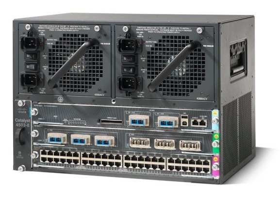
Cisco Catalyst 4503-E Switch
- Field Notice: FN - 62997 - Software Release 12.2(25)EWA10, 12.2(31)SGA2 and 12.2(31)SGA3 May Report Some WS-X4548-GB-RJ45V PoE Cards as Faulty On Bootup
- Field Notice: FN - 22253 - Catalyst 4500 Series Chassis Fan Tray Recall
Field Notices
- Cisco CatOS Telnet, HTTP and SSH Vulnerability
Security Advisories, Responses and Notices
-
Release and Compatibility
-
Optical Compatibility
Compatibility Information
-
Cisco IOS Release Notes for the Catalyst 4500 Series Switch
-
Cisco IOS Release Notes for the Catalyst 4500-E Series Switches
- Release Notes for the Cisco Catalyst 4500E Series Switch, Cisco IOS XE 3.11.xE
- Release Notes for the Catalyst 4500E Series Switch, Cisco IOS XE 3.10.xE
- Release Notes for the Catalyst 4500E Series Switch, Cisco IOS XE 3.9.xE
- Release Notes for the Catalyst 4500E Series Switch, Cisco IOS XE 3.8.xE
- Release Notes for the Catalyst 4500E Series Switch, Cisco IOS XE 3.7xE
- Release Notes for the Catalyst 4500E Series Switch, Cisco IOS XE 3.6.xE
Release Notes
-
-
Reference
-
Resources and Tools
-
Cisco IOS Command Reference Guides for the Catalyst 4500 Series Switch
-
Wireless
-
Open Source
-
Feature Command References
Command References
- Documentation Roadmap, Cisco IOS XE Release 3E, IOS Release 15E (Cisco Catalyst 4500 Series Switch)
Documentation Roadmaps
- Open Source Used In Cisco IOS XE 3.9.1E (PDF - 772 KB)
Licensing Information
-
-
Design
-
EtherChannel
-
Spanning Tree Protocol
- Multicast in a Campus Network: CGMP and IGMP Snooping
- Best Practices for Catalyst 6500/6000 Series and Catalyst 4500/4000 Series Switches Running Cisco IOS Software (PDF - 611 KB)
- Multicast Catalyst Switches Support Matrix (PDF - 133 KB)
Design TechNotes
-
-
Install and Upgrade
- Cisco SFP and SFP+ Transceiver Module Installation Notes
- 思科 Catalyst 4500 E 系列管理引擎 9-E 的安装和配置说 明 (PDF)
- Nota de instalação e configuração do mecanismo de supervisão Cisco Catalyst 4500 E-Series Supervisor Engine 9-E (PDF)
- Cisco Catalyst 4500 E シリーズ Supervisor Engine 9-E インストレー ション コンフィギュレーション ノート (PDF)
- Nota per l'installazione e la configurazione di Cisco Catalyst serie 4500 E Supervisor Engine 9-E (PDF)
- Guide d'installation et de configuration du moteur de supervision Supervisor Engine 9-E pour la série Cisco Catalyst 4500 E (PDF)
- Nota de instalación y configuración para el motor supervisor 9-E de Cisco Catalyst de la serie 4500 E (PDF)
- Installations- und Konfigurationshinweis für die Cisco Catalyst 4500 E-Serie Supervisor Engine 9-E (PDF)
- Installation and Configuration Note for Cisco Catalyst 4500 E-Series Supervisor Engine 9-E
- Catalyst 4500 E-Series Installation Guide
- Installation Note for the Catalyst 4500 Series Center Mount System
- Catalyst 4500 Series Regulatory Compliance and Safety Information
- Installation Note for Fan Tray Assemblies in Catalyst 4500 Series Switches
- Catalyst 4500 Series Supervisor Engines and Switching Modules Installation Note
- Catalyst 4500 E-Series Module Installation Note
Install and Upgrade Guides
- Configuration example to migrate Spanning Tree from PVST+ to MST (ZIP - 92 KB)
- Best Practices for Catalyst 6500/6000 Series and Catalyst 4500/4000 Series Switches Running Cisco IOS Software (PDF - 611 KB)
Install and Upgrade TechNotes
-
Configuration
- Understand the Spanning Tree PortFast BPDU Guard Enhancement
- Configure Catalyst Switched Port Analyzer (SPAN): Example
- Configure the Catalyst 4500 Series Switch VSS Member Replacement
- Multicast in a Campus Network: CGMP and IGMP Snooping
- Quad Supervisor VSS Deployment on Catalyst 4500 Switches Configuration Example
- Configuring Trunking Between a Catalyst 1900 and any Switch Running CatOS Software
- Configuring EtherChannel and 802.1Q Trunking with Catalyst 2948G-L3s and CatOS Based Switches (ZIP - 37 KB)
- Configuring FEC and ISL/802.1q Trunking Between a CatOS Switch and External Router (ZIP - 51 KB)
- Configuration example to migrate Spanning Tree from PVST+ to MST (ZIP - 92 KB)
- Spanning Tree from PVST+ to Rapid-PVST Migration Configuration Example (ZIP - 45 KB)
- Best Practices for Catalyst 6500/6000 Series and Catalyst 4500/4000 Series Switches Running Cisco IOS Software (PDF - 611 KB)
- Catalyst Switches for Microsoft Network Load Balancing Configuration Example
- External RADIUS Server EAP Authentication with 5760/3850 WLC Configuration Example
- Catalyst 4500 Series Switches Wireshark Feature Configuration Example
- Using PortFast and Other Commands to Fix Workstation Startup Connectivity Delays
Configuration Examples and TechNotes
-
Cisco IOS Software Configuration Guide for the Catalyst 4500 Series Switch
-
Wireless
-
Open Source
-
Feature Configuration Guides
Configuration Guides
-
Maintain and Operate
- Cisco Small Form-Factor Pluggable (SFP) Transceiver Modules Maintenance and Troubleshooting (PDF - 345 KB)
Maintain and Operate TechNotes
-
Troubleshooting
-
Cisco IOS XE System Message Guides for the Catalyst 4500 Series Switch
-
Cisco IOS 12.X System Message Guides for the Catalyst 4500 Series Switch
- System Message Guide for Cisco Catalyst Series Switches, Cisco IOS Release 15.2(6)E2/XE 3.102E (XLSX - 1 MB)
Error and System Messages
- Recover Passwords for Catalyst 4500/4900 Switches with Supervisor Engine
- Catalyst 4500 Series Switches with VSS Password Recovery Procedure
- Password Recovery for Catalyst Switches Running CatOS
Password Recovery
- Troubleshooting High CPU on the Catalyst 4500-E Series Switch
Troubleshooting Guides
- Understand the Spanning Tree PortFast BPDU Guard Enhancement
- Understand VLAN Trunk Protocol (VTP)
- Troubleshoot HSRP Common Issues
- Determine the Serial Number of Catalyst Switch Components
- Understand EtherChannel Load Balance and Redundancy on Catalyst Switches
- Understand the Terminal Connection to a Console Port on Catalyst Switches
- Review Catalyst Switch Cable, Connector, & AC Power Cord Guide
- SNMP Input Queue Full
- Troubleshoot DHCP in Enterprise Networks
- Troubleshoot Hardware Issues on Catalyst 4500/4000 Switches
- Troubleshoot High CPU Utilization on Catalyst 4500 Switches
- Multicast Catalyst Switches Support Matrix
- Connecting a Modem to the Console Port on Catalyst Switches
- Get Started with SUP8E 4500 Wireless: Initial Installation and Troubleshooting
- Use MAC ACL for Layer 2 Control Frames on Catalyst 4500 Series Switches
Troubleshooting TechNotes
-
-
Literature
- Best Practices for Catalyst 6500/6000 Series and Catalyst 4500/4000 Series Switches Running Cisco IOS Software (PDF - 611 KB)
White Papers
-
Log in to see available downloads.
-
-
Below are the models within the Cisco Catalyst 4500 Series Switches.
Unless specified, documentation for the Cisco Catalyst 4500 Series Switches is applicable to all models.
- Supported Models:
- Catalyst 4503-E Switch
- Catalyst 4506-E Switch
- Catalyst 4507R+E Switch
- Catalyst 4510R Switch
- Catalyst 4510R+E Switch
- Retired Models:
- Catalyst 4503 Switch
- Catalyst 4506 Switch
- Catalyst 4507R Switch
- Catalyst 4507R-E Switch
- Catalyst 4510R-E Switch
