-
Cisco MDS 9000 Family Fabric Manager Configuration Guide, Release 3.x
-
Index
-
New and Changed Information
-
Preface
- Getting Started
- Installation and Switch Management
- Switch Configuration
-
Fabric Configuration
-
Configuring and Managing VSANs
-
SAN Device Virtualization
-
Creating Dynamic VSANs
-
Configuring Inter-VSAN Routing
-
Distributing Device Alias Services
-
Configuring and Managing Zones
-
Configuring Fibre Channel Routing Services and Protocols
-
Dense Wavelength Division Multiplexing
-
Managing FLOGI, Name Server, FDMI, and RSCN Databases
-
Discovering SCSI Targets
-
Configuring FICON
-
Advanced Features and Concepts
-
-
Security
-
Configuring FIPS
-
Configuring Users and Common Roles
-
Configuring SNMP
-
Configuring RADIUS and TACACS+
-
Configuring IPv4 Access Control Lists
-
Configuring Certificate Authorities and Digital Certificates
-
Configuring IPsec Network Security
-
Configuring FC-SP and DHCHAP
-
Configuring Port Security
-
Configuring Fabric Binding
-
- IP Services
- Intelligent Storage Services
- Network and Switch Monitoring
- Traffic Management
- Troubleshooting
-
Launching Fabric Manager in Cisco SAN-OS Releases Prior to 3.2(1)
-
Cisco Fabric Manager Unsupported Feature List
-
Interface Nonoperational Reason Codes
-
Managing Cisco FabricWare
-
Configuration Limits for Cisco MDS SAN-OS Release 3.1(x) and 3.2(x)
-
 Feedback
Table Of Contents
Configuring FlexAttach Virtual pWWN
FlexAttach Virtual pWWN Guidelines and Requirements
Configuring FlexAttach Virtual pWWN
Enabling FlexAttach Virtual pWWN
Automatically Enabling FlexAttach Virtual pWWN
Launching FlexAttach in Fabric Manager
Manually Enabling FlexAttach Virtual pWWN
Debugging FlexAttach Virtual pWWN
Security Settings for FlexAttach Virtual pWWN
FlexAttach Virtual pWWN CFS Distribution
Difference Between San Device Virtualization and FlexAttach Port Virtualization
Configuring FlexAttach Virtual pWWN
This chapter describes the FlexAttach virtual port world-wide name (pWWN) feature and includes the following sections:
•
About FlexAttach Virtual pWWN
•
•
•
About FlexAttach Virtual pWWN
FlexAttach virtual pWWN feature facilitates server and configuration management. In a SAN environment, the server installation or replacement, requires interaction and coordination among the SAN and server administrators. For coordination, it is important that the SAN configuration does not change when a new server is installed, or when an existing server is replaced. FlexAttach virtual pWWN minimizes the interaction between the server administrator and the SAN administrator by abstracting the real pWWN using virtual pWWNs.
When FlexAttach virtual pWWN is enabled on an interface, a virtual pWWN is assigned to the server interface. The real pWWN is replaced by a virtual pWWN, which is used for SAN configuration like zoning.
Administrators can benefit from FlexAttach in the following scenarios:
•
•
•
•
FlexAttach Virtual pWWN Guidelines and Requirements
Following are recommended guidelines and requirements when deploying FlexAttach virtual pWWN:
•
•
•
Configuring FlexAttach Virtual pWWN
This section describes how to configure FlexAttach virtual pWWN feature and includes the following topics:
•
•
•
•
Enabling FlexAttach Virtual pWWN
The FlexAttach virtual pWWN feature is enabled automatically, manually, or by mapping pWWN to virtual pWWN. Figure 14-1 shows how the FlexAttach virtual pWWN feature is enabled.
Automatically Enabling FlexAttach Virtual pWWN
The virtual pWWN is enabled automatically on all the NPV switches, or per port on the NPV box. When enabled automatically, a virtual WWN is generated from the device switch WWN. This WWN is used as the virtual pWWN. Virtual pWWNs are generated using the local switch WWNs.
Note
To enable virtual pWWN automatically for all the Interfaces, follow these steps:
Step 1
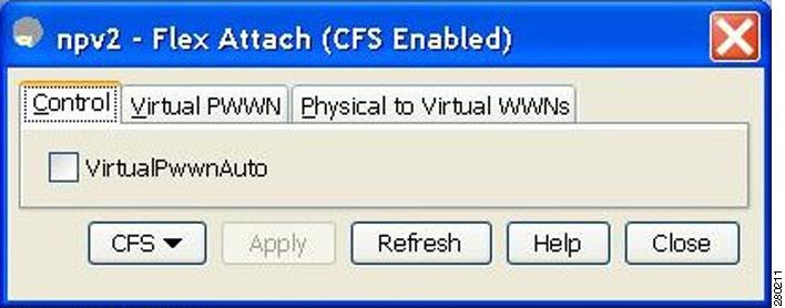
Figure 14-1 FlexAttach in Device Manager
You see FlexAttach window.
Figure 14-2 FlexAttach Window in Device Manager
Step 2
Note
•
Launching FlexAttach in Fabric Manager
To launch FlexAttach in Fabric Manager follow these steps:
Step 1
Step 2
Step 3
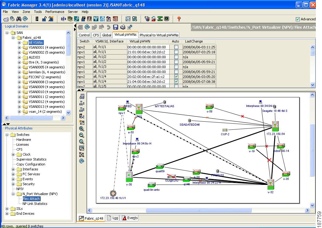
The FlexAttach menus display in the Information pane, as shown in Figure 14-3.
Figure 14-3 FlexAttach Menu
Manually Enabling FlexAttach Virtual pWWN
You can manually assign a WWN to the interface, without generating it through the switch. Several checks are done by the NPV core to ensure the uniqueness of virtual pWWNs in the switch. When duplicate virtual pWWNs are configured, the subsequent logins are rejected by the NPV core switch.
Note
•
To enable virtual pWWN on each interface manually, follow the steps below:
Step 1
You see virtual pWWN tab view.
Figure 14-4 Virtual PWWN Tab View in Device Manager
The Virtual pWWN tab view displays a list of the interfaces.
Step 2
Note
Follow Step 2 to automatically generate the virtual port WWN value for the selected interface in Fabric Manager, as shown in Figure 14-5.
Figure 14-5 Virtual pWWN Tab View in Fabric Manager
Note
Mapping pWWN to Virtual pWWN
You can configure virtual pWWNs through real pWWNs. This is required for NPIV hosts containing multiple pWWNs, of which only FLOGI is mapped to the virtual pWWN. Subsequent FDSIDs will have different mappings.
Several checks are done by the NPV core to ensure the uniqueness of virtual pWWNs in the switch across the NPV switches. When duplicate virtual pWWNs are configured, the subsequent logins are rejected by the NPV core switch.To map pWWN to virtual pWWN, follow these steps:
Step 1
Step 2
Figure 14-6 Physical to Virtual WWNs Tab View in Device Manager
The LastChange field displays the time when the virtual pWWN was changed.
Note
Figure 14-7 shows the Physical to Virtual WWNs tab view.
Figure 14-7 Physical to Virtual WWNs Tab View in Fabric Manager
Note
Debugging FlexAttach Virtual pWWN
For specific problems and the workarounds, refer to the following real-time scenarios:
Security Settings for FlexAttach Virtual pWWN
Security settings for FlexAttach virtual pWWN feature are done by port security at the NPV core. Node WWN of the end device is used to provide physical security.
For more details on enabling port security, see Chapter 37, "Configuring Port Security".
FlexAttach Virtual pWWN CFS Distribution
FlexAttach virtual pWWN configuration is distributed for CFS through IPv4, and is enabled by default. The FlexAttach virtual pWWN distribution, by default, is on CFS region 201. The CFS region 201 links only to the NPV enabled switches. Other CFS feature like syslog is on region 0. Region 0 will be linked through IPv4 for all NPV switches on the same physical fabric. If CFS has an option to link through IPv4 or ISL, then CFS will select the ISL path.
Note
Difference Between San Device Virtualization and FlexAttach Port Virtualization
Figure 14-8 describes the difference between SAN Device Virtualization (SDV) and FlexAttach Port Virtualization.
Figure 14-8 Difference Between SDV and FlexAttach Virtualization