-
Cisco MDS 9000 Family Fabric Manager Configuration Guide, Release 3.x
-
Index
-
New and Changed Information
-
Preface
- Getting Started
- Installation and Switch Management
- Switch Configuration
-
Fabric Configuration
-
Configuring and Managing VSANs
-
SAN Device Virtualization
-
Creating Dynamic VSANs
-
Configuring Inter-VSAN Routing
-
Distributing Device Alias Services
-
Configuring and Managing Zones
-
Configuring Fibre Channel Routing Services and Protocols
-
Dense Wavelength Division Multiplexing
-
Managing FLOGI, Name Server, FDMI, and RSCN Databases
-
Discovering SCSI Targets
-
Configuring FICON
-
Advanced Features and Concepts
-
-
Security
-
Configuring FIPS
-
Configuring Users and Common Roles
-
Configuring SNMP
-
Configuring RADIUS and TACACS+
-
Configuring IPv4 Access Control Lists
-
Configuring Certificate Authorities and Digital Certificates
-
Configuring IPsec Network Security
-
Configuring FC-SP and DHCHAP
-
Configuring Port Security
-
Configuring Fabric Binding
-
- IP Services
- Intelligent Storage Services
- Network and Switch Monitoring
- Traffic Management
- Troubleshooting
-
Launching Fabric Manager in Cisco SAN-OS Releases Prior to 3.2(1)
-
Cisco Fabric Manager Unsupported Feature List
-
Interface Nonoperational Reason Codes
-
Managing Cisco FabricWare
-
Configuration Limits for Cisco MDS SAN-OS Release 3.1(x) and 3.2(x)
-
 Feedback
Table Of Contents
Configuring the SAN Extension Tuner
Configuring the SAN Extension Tuner
Using the SAN Extension Tuner Wizard
Configuring the SAN Extension Tuner
The SAN extension tuner (SET) feature is unique to the Cisco MDS 9000 Family of switches. This feature helps you optimize FCIP performance by generating either direct access (magnetic disk) or sequential access (magnetic tape) SCSI I/O commands and directing such traffic to a specific virtual target. You can specify the size of the test I/O transfers and how many concurrent or serial I/Os to generate while testing. The SET reports the resulting I/Os per second (IOPS) and I/O latency, which helps you determine the number of concurrent I/Os needed to maximize FCIP throughput.
This chapter includes the following sections:
•
About the SAN Extension Tuner
•
•
About the SAN Extension Tuner
Note
Note
Applications such as remote copy and data backup use FCIP over an IP network to connect across geographically distributed SANs. To achieve maximum throughput performance across the fabric, you can tune the following configuration parameters:
•
•
•
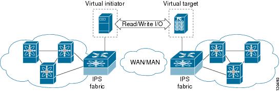
SET is implemented in IPS ports. When enabled, this feature can be used to generate SCSI I/O commands (read and write) to the virtual target based on your configured options (see Figure 41-1).
Figure 41-1 SCSI Command Generation to the Virtual Target
The SET feature assists with tuning by generating varying SCSI traffic workloads. It also measures throughput and response time per I/ O over an FCIP link.
Before tuning the SAN fabric, be aware of the following guidelines:
•
–
–
–
–
–
•
•
•
•
•
•
SAN Extension Tuner Setup
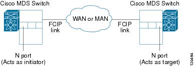
Figure 41-2 provides a sample physical setup in which the virtual N ports are created on ports that are not a part of the FCIP link for which the throughput and latency is measured.
Figure 41-2 N Port Tuning Configuration Physical Example
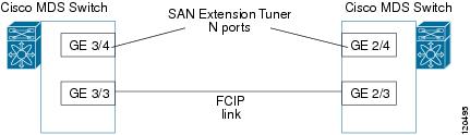
Figure 41-3 provides a sample logical setup in which the virtual N ports are created on ports that are not a part of the FCIP link for which the throughput and latency is measured.
Figure 41-3 Logical Example of N Port Tuning for a FCIP Link
Data Pattern
By default, an all-zero pattern is used as the pattern for data generated by the virtual N ports. You can optionally specify a file as the data pattern to be generated by selecting a data pattern file from one of three locations: the bootflash: directory, the volatile: directory, or the slot0: directory. This option is especially useful when testing compression over FCIP links. You can also use Canterbury corpus or artificial corpus files for benchmarking purposes.
License Prerequisites
To use the SET, you need to obtain the SAN_EXTN_OVER_IP license (see Chapter 10, "Obtaining and Installing Licenses").
Configuring the SAN Extension Tuner
This section includes the following topics:
Tuning Guidelines
To tune the required FCIP link, follow these steps:
Step 1
Step 2
Step 3
Step 4
Step 5
Step 6
Using the SAN Extension Tuner Wizard
Use the SAN Extension Tuner wizard to perform the these tasks:
•
•
•
•
•
•
To tune the required FCIP link using the SAN Extension Tuner Wizard in Fabric Manager, follow these steps:
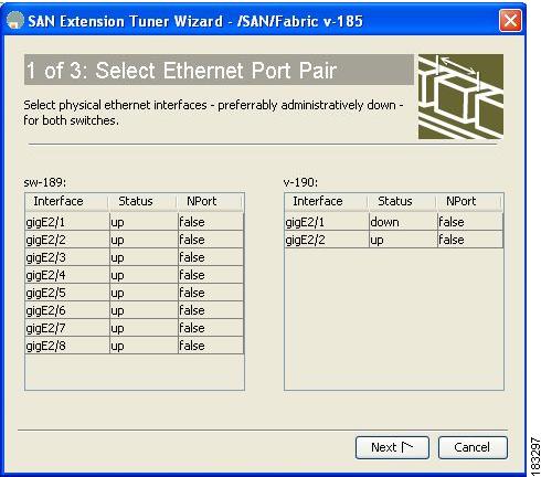
Step 1
You see the Select Ethernet Port Pair dialog box (see Figure 41-4).
Figure 41-4 Select Ethernet Port Pair Dialog Box
Step 2
Note
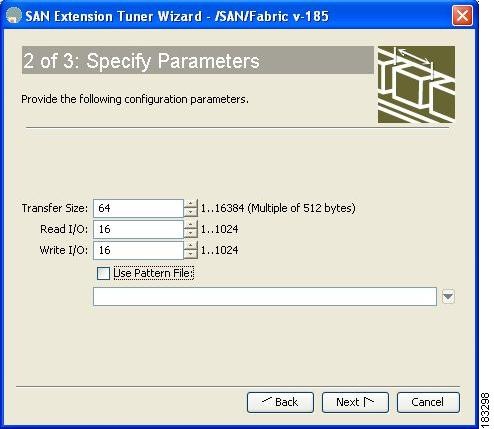
You see the Specify Parameters dialog box (see Figure 41-5).
Step 3
Figure 41-5 Specify Parameters Dialog Box
Step 4
a.
b.
c.
Note
d.
Step 5
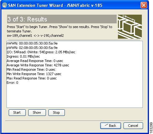
You see the Results dialog box (see Figure 41-6).
Figure 41-6 Results Dialog Box
Step 6
Step 7
Step 8
Default Settings
Table 41-1 lists the default settings for tuning parameters.