-
Cisco MDS 9000 Family Fabric Manager Configuration Guide, Release 3.x
-
Index
-
New and Changed Information
-
Preface
- Getting Started
- Installation and Switch Management
- Switch Configuration
-
Fabric Configuration
-
Configuring and Managing VSANs
-
SAN Device Virtualization
-
Creating Dynamic VSANs
-
Configuring Inter-VSAN Routing
-
Distributing Device Alias Services
-
Configuring and Managing Zones
-
Configuring Fibre Channel Routing Services and Protocols
-
Dense Wavelength Division Multiplexing
-
Managing FLOGI, Name Server, FDMI, and RSCN Databases
-
Discovering SCSI Targets
-
Configuring FICON
-
Advanced Features and Concepts
-
-
Security
-
Configuring FIPS
-
Configuring Users and Common Roles
-
Configuring SNMP
-
Configuring RADIUS and TACACS+
-
Configuring IPv4 Access Control Lists
-
Configuring Certificate Authorities and Digital Certificates
-
Configuring IPsec Network Security
-
Configuring FC-SP and DHCHAP
-
Configuring Port Security
-
Configuring Fabric Binding
-
- IP Services
- Intelligent Storage Services
- Network and Switch Monitoring
- Traffic Management
- Troubleshooting
-
Launching Fabric Manager in Cisco SAN-OS Releases Prior to 3.2(1)
-
Cisco Fabric Manager Unsupported Feature List
-
Interface Nonoperational Reason Codes
-
Managing Cisco FabricWare
-
Configuration Limits for Cisco MDS SAN-OS Release 3.1(x) and 3.2(x)
-
 Feedback
Table Of Contents
Advanced Features and Concepts
Timer Configuration Across All VSANs
Enabling or Disabling fctimer Distribution
Configuring a Secondary MAC Address
Verifying the Company ID Configuration
Verifying Interoperating Status
Advanced Features and Concepts
This chapter describes the advanced features provided in switches in the Cisco MDS 9000 Family. It includes the following sections:
•
Fibre Channel Time Out Values
Common Information Model
Common Information Model (CIM) is an object-oriented information model that extends the existing standards for describing management information in a network/enterprise environment.
CIM messages are independent of platform and implementation because they are encoded in N Extensible Markup Language (XML). CIM consists of a specification and a schema. The specification defines the syntax and rules for describing management data and integrating with other management models. The schema provides the actual model descriptions for systems, applications, networks, and devices.
For more information about CIM, refer to the specification available through the Distributed Management Task Force (DMTF) website at the following URL: http://www.dmtf.org/
For further information about Cisco MDS 9000 Family support for CIM servers, refer to the Cisco MDS 9000 Family CIM Programming Reference Guide.
A CIM client is required to access the CIM server. The client can be any client that supports CIM.
For added security, you can install an SSL certificate to encrypt the login information and enable the HTTPS server before enabling the CIM server. The CIM server is disabled by default. If you do not enable the HTTPS server, the standard HTTP server is enabled (default).
To configure a CIM server using the HTTPS or HTTP protocols, refer to the Cisco MDS 9000 Family Configuration Guide.
Fibre Channel Time Out Values
You can modify Fibre Channel protocol related timer values for the switch by configuring the following time out values (TOVs):
•
•
•
Note
This section includes the following topics:
•
•
Timer Configuration Across All VSANs
You can modify Fibre Channel protocol related timer values for the switch.
Caution
Note
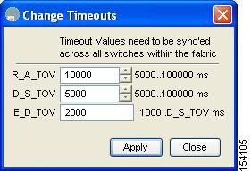
To configure timers in Fabric Manager, expand Switches > FC Services and then select Timers & Policies in the Physical Attributes pane. You see the timers for multiple switches in the Information pane. Click the Change Timeouts button to configure the timeout values.
You see the dialog box as shown in Figure 29-1.
Figure 29-1 Configure Timers in Fabric Manager
To configure timers in Device Manager, click FC > Advanced > Timers/Policies. You see the timers for a single switch in the dialog box as shown in Figure 29-2.
Figure 29-2 Configure Timers in Device Manager
Timer Configuration Per-VSAN
You can also issue the fctimer for a specified VSAN to configure different TOV values for VSANs with special links like FC or IP tunnels. You can configure different E_D_TOV, R_A_TOV, and D_S_TOV values for individual VSANs. Active VSANs are suspended and activated when their timer values are changed.
Caution
Note
If a switch is downgraded to Cisco MDS SAN-OS Release 1.2 or 1.1 after the timer is configured for a VSAN, an error message is issued to warn against strict incompatibilities. the Cisco MDS 9000 Family Troubleshooting Guide.
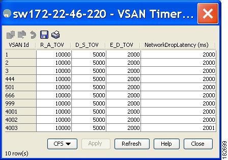
To configure per-VSAN Fiber Channel timers using Device Manager, follow these steps:
Step 1
You see the VSANs Timer dialog box as shown in Figure 29-3.
Figure 29-3 VSAN Timers in Device Manager
Step 2
Step 3
About fctimer Distribution
You can enable per-VSAN fctimer fabric distribution for all Cisco MDS switches in the fabric. When you perform fctimer configurations, and distribution is enabled, that configuration is distributed to all the switches in the fabric.
You automatically acquire a fabric-wide lock when you issue the first configuration command after you enabled distribution in a switch. The fctimer application uses the effective and pending database model to store or commit the commands based on your configuration.
See Chapter 13, "Using the CFS Infrastructure," for more information on the CFS application.
Enabling or Disabling fctimer Distribution
To enable and distribute fctimer configuration changes using Device Manager, follow these steps:
Step 1
You see the VSANs Timer dialog box as shown in Figure 29-3.
Step 2
Step 3
Step 4
When you commit the fctimer configuration changes, the effective database is overwritten by the configuration changes in the pending database and all the switches in the fabric receive the same configuration. When you commit the fctimer configuration changes without implementing the session feature, the fctimer configurations are distributed to all the switches in the physical fabric.
Database Merge Guidelines
See the "CFS Merge Support" section on page 13-11 for detailed concepts.
When merging two fabrics, follow these guidelines:
•
–
–
–
•
Note
World Wide Names
The world wide name (WWN) in the switch is equivalent to the Ethernet MAC address. As with the MAC address, you must uniquely associate the WWN to a single device. The principal switch selection and the allocation of domain IDs rely on the WWN. The WWN manager, a process-level manager residing on the switch's supervisor module, assigns WWNs to each switch.
Cisco MDS 9000 Family switches support three network address authority (NAA) address formats (see Table 29-1).
Caution
This section includes the following topics:
•
•
Displaying WWN Information
To display WWN information using Device Manager, choose FC > Advanced > WWN Manager. You see the list of allocated WWNs.
Link Initialization WWN Usage
Exchange Link Protocol (ELP) and Exchange Fabric Protocol (EFP) use WWNs during link initialization. The usage details differ based on the Cisco SAN-OS software release:
Both ELPs and EFPs use the VSAN WWN by default during link initialization. However, the ELP usage changes based on the peer switch's usage:
•
•
Note
Configuring a Secondary MAC Address
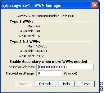
To allocate secondary MAC addresses using Device Manager, follow these steps:
Step 1
You see the list of allocated WWNs as shown in Figure 29-4.
Figure 29-4 Allocated World Wide Names in Device Manager
Step 2
Step 3
FC ID Allocation for HBAs
Fibre Channel standards require a unique FC ID to be allocated to an N port attached to a Fx port in any switch. To conserve the number of FC IDs used, Cisco MDS 9000 Family switches use a special allocation scheme.
Some HBAs do not discover targets that have FC IDs with the same domain and area. Prior to Cisco SAN-OS Release 2.0(1b), the Cisco SAN-OS software maintained a list of tested company IDs that do not exhibit this behavior. These HBAs were allocated with single FC IDs, and for others a full area was allocated.
The FC ID allocation scheme available in Release 1.3 and earlier, allocates a full area to these HBAs. This allocation isolates them to that area and are listed with their pWWN during a fabric login. The allocated FC IDs are cached persistently and are still available in Cisco SAN-OS Release 2.0(1b) (see the "FC ID Allocation for HBAs" section).
To allow further scalability for switches with numerous ports, the Cisco SAN-OS software maintains a list of HBAs exhibiting this behavior. Each HBA is identified by its company ID (also known as Organizational Unique Identifier, or OUI) used in the pWWN during a fabric log in. Hence a full area is allocated to the N ports with company IDs that are listed and for the others, a single FC ID is allocated. Irrespective of the kind (whole area or single) of FC ID allocated, the FC ID entries remain persistent.
This section includes the following topics:
•
Default Company ID list
All switches in the Cisco MDS 9000 Family that ship with Cisco SAN-OS Release 2.0(1b) or later, contain a default list of company IDs that require area allocation. Using the company ID reduces the number of configured persistent FC ID entries. You can configure or modify these entries using the CLI.
Caution
1. Shut down the port connected to the HBA.
2. Clear the persistent FC ID entry.
3. Get the company ID from the Port WWN.
4. Add the company ID to the list that requires area allocation.
5. Bring up the port.
The list of company IDs have the following characteristics:
•
•
•
•
Tip
Refer to the Cisco MDS 9000 Family CLI Configuration Guide to change the FC ID allocation.
Verifying the Company ID Configuration
To view the configured company IDs using Device Manager, choose FC > Advanced > FcId Area Allocation. You can implicitly derive the default entries shipped with a specific release by combining the list of Company IDs displayed without any identification with the list of deleted entries.
Some WWN formats do not support company IDs. In these cases, you may need to configure the FC ID persistent entry.
Switch Interoperability
Interoperability enables the products of multiple vendors to come into contact with each other. Fibre Channel standards guide vendors towards common external Fibre Channel interfaces.
If all vendors followed the standards in the same manner, then interconnecting different products would become a trivial exercise. However, not all vendors follow the standards in the same way, thus resulting in interoperability modes. This section briefly explains the basic concepts of these modes.
Each vendor has a regular mode and an equivalent interoperability mode, which specifically turns off advanced or proprietary features and provides the product with a more amiable standards compliant implementation.
This section includes the following topics:
•
About Interop Mode
Cisco SAN-OS software supports the following four interop modes:
•
•
•
•
For information about configuring interop modes 2, 3, and 4, refer to the Cisco MDS 9000 Family Switch-to-Switch Interoperability Configuration Guide.
Table 29-2 lists the changes in switch behavior when you enable interoperability mode. These changes are specific to switches in the Cisco MDS 9000 Family while in interop mode.
Configuring Interop Mode 1
The interop mode1 in Cisco MDS 9000 Family switches can be enabled disruptively or nondisruptively.
Note
msplmgmtdeactivatecommand must explicitly be run prior to connecting from a Brocade switch to either Cisco MDS 9000 Family switches or to McData switches. This command uses Brocade proprietary frames to exchange platform information, which Cisco MDS 9000 Family switches or McData switches do not understand. Rejecting these frames causes the common E ports to become isolated.To configure interop mode 1 for a VSAN using Fabric Manager, follow these steps:
Step 1
Step 2
Step 3
Step 4
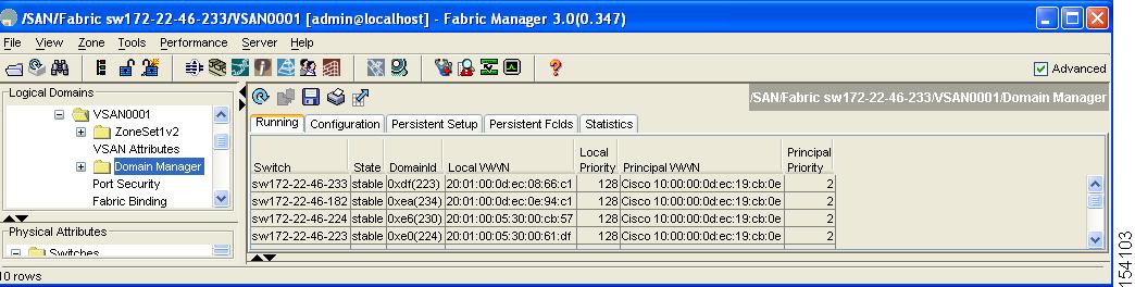
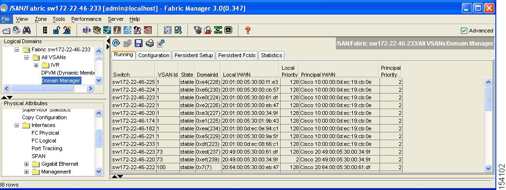
You see the Domain Manager configuration in the Information pane as shown in Figure 29-5.
Figure 29-5 Domain Manager Configuration
Step 5
a.
b.
c.
Note
Note
Step 6
Note
a.
b.
c.
Step 7
Verifying Interoperating Status
This section highlights the steps used to verify if the fabric is up and running in interoperability mode.
To verify the interoperability status of any switch in the Cisco MDS 9000 Family using Fabric Manager, follow these steps:
Step 1
Step 2
Step 3
Step 4
Figure 29-6 Domain Manager Information
Step 5
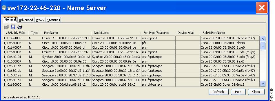
You see the Name Server dialog box as shown in Figure 29-7.
Figure 29-7 Name Server Dialog Box
Step 6
Note
Default Settings
Table 29-3lists the default settings for the features included in this chapter.
Table 29-4 Default Settings for Advanced Features
D_S_TOV
5,000 msec
E_D_TOV
2,000 msec
R_A_TOV
10,000 msec
Interop mode
Disabled