-
Cisco MDS 9000 Family Fabric Manager Configuration Guide, Release 3.x
-
Index
-
New and Changed Information
-
Preface
- Getting Started
- Installation and Switch Management
- Switch Configuration
-
Fabric Configuration
-
Configuring and Managing VSANs
-
SAN Device Virtualization
-
Creating Dynamic VSANs
-
Configuring Inter-VSAN Routing
-
Distributing Device Alias Services
-
Configuring and Managing Zones
-
Configuring Fibre Channel Routing Services and Protocols
-
Dense Wavelength Division Multiplexing
-
Managing FLOGI, Name Server, FDMI, and RSCN Databases
-
Discovering SCSI Targets
-
Configuring FICON
-
Advanced Features and Concepts
-
-
Security
-
Configuring FIPS
-
Configuring Users and Common Roles
-
Configuring SNMP
-
Configuring RADIUS and TACACS+
-
Configuring IPv4 Access Control Lists
-
Configuring Certificate Authorities and Digital Certificates
-
Configuring IPsec Network Security
-
Configuring FC-SP and DHCHAP
-
Configuring Port Security
-
Configuring Fabric Binding
-
- IP Services
- Intelligent Storage Services
- Network and Switch Monitoring
- Traffic Management
- Troubleshooting
-
Launching Fabric Manager in Cisco SAN-OS Releases Prior to 3.2(1)
-
Cisco Fabric Manager Unsupported Feature List
-
Interface Nonoperational Reason Codes
-
Managing Cisco FabricWare
-
Configuration Limits for Cisco MDS SAN-OS Release 3.1(x) and 3.2(x)
-
 Feedback
Table Of Contents
Cisco SAN-OS Features Using CFS
Unrestricted Uncoordinated Distributions
Disabling CFS Distribution on a Switch
Enabling CFS for an Application
Displaying CFS Configuration Information
Managing CFS Regions Using Fabric Manager
Assigning Features to CFS Regions
Moving a Feature to a Different Region
Removing a Feature from a Region
CFS Example Using Fabric Manager
CFS Example Using Device Manager
Using the CFS Infrastructure
The Cisco MDS SAN-OS software uses the Cisco Fabric Services (CFS) infrastructure to enable efficient database distribution and to foster device flexibility. It simplifies SAN provisioning by automatically distributing configuration information to all switches in a fabric.
Several Cisco MDS SAN-OS applications use the CFS infrastructure to maintain and distribute the contents of a particular application's database.
This chapter contains the following sections:
•
Disabling CFS Distribution on a Switch
•
•
•
•
About CFS
Many features in the Cisco MDS switches require configuration synchronization in all switches in the fabric. Maintaining configuration synchronization across a fabric is important to maintain fabric consistency. In the absence of a common infrastructure, such synchronization is achieved through manual configuration at each switch in the fabric. This process is tedious and error prone.
Cisco Fabric Services (CFS) provides a common infrastructure for automatic configuration synchronization in the fabric. It provides the transport function as well as a rich set of common services to the applications. CFS has the ability to discover CFS capable switches in the fabric and discovering application capabilities in all CFS capable switches.
This section includes the following topics:
•
Cisco SAN-OS Features Using CFS
The following Cisco SAN-OS features use the CFS infrastructure:
•
•
•
•
•
•
•
•
•
•
•
•
•
•
•
•
•
•
•
CFS Features
CFS has the following features:
•
•
–
–
–
•
–
–
–
•
CFS Protocol
The CFS functionality is independent of the lower layer transport. Currently, in Cisco MDS switches, the CFS protocol layer resides on top of the FC2 layer and is peer-to-peer with no client-server relationship. CFS uses the FC2 transport services to send information to other switches. CFS uses a proprietary SW_ILS (0x77434653) protocol for all CFS packets. CFS packets are sent to or from the switch domain controller addresses.
CFS can also use IP to send information to other switches (see the "CFS Distribution over IP" section).
Applications that use CFS are completely unaware of the lower layer transport.
CFS Distribution Scopes
Different applications on the Cisco MDS 9000 Family switches need to distribute the configuration at various levels:
•
Applications that operate within the scope of a VSAN have the configuration distribution restricted to the VSAN. An example application is port security where the configuration database is applicable only within a VSAN.
•
Applications might need to distribute the configuration to the entire physical topology spanning several VSANs. Such applications include NTP and DPVM (WWN based VSAN), which are independent of VSANs.
•
Applications might only operate between selected switches in the fabric. An example application is SCSI Flow Services, which operates between two switches.
CFS Distribution Modes
CFS supports different distribution modes to support different application requirements: coordinated and uncoordinated distributions. Both modes are mutually exclusive. Only one mode is allowed at any given time.
Uncoordinated Distribution
Uncoordinated distributions are used to distribute information that is not expected to conflict with that from a peer. An example is local device registrations such as iSNS. Parallel uncoordinated distributions are allowed for an application.
Coordinated Distribution
Coordinated distributions can have only one application distribution at a given time. CFS uses locks to enforce this. A coordinated distribution is not allowed to start if locks are taken for the application anywhere in the fabric. A coordinated distribution consists of three stages:
1.
2.
3.
Coordinated distribution has two variants:
•
•
Coordinated distributions are used to distribute information that can be manipulated and distributed from multiple switches, for example, the port security configuration.
Unrestricted Uncoordinated Distributions
Unrestricted uncoordinated distributions allow multiple parallel distributions in the fabric in the presence of an existing coordinated distribution. Unrestricted uncoordinated distributions are allowed to run in parallel with all other types of distributions.
Disabling CFS Distribution on a Switch
By default, CFS distribution is enabled. Applications can distribute data and configuration information to all CFS-capable switches in the fabric where the applications exist. This is the normal mode of operation.
You can globally disable CFS on a switch, to isolate the applications using CFS from fabric-wide distributions while maintaining physical connectivity. When CFS is globally disabled on a switch, CFS operations are restricted to the switch and all CFS commands continue to function as if the switch were physically isolated.
To globally disable or enable CFS distribution on a switch using Fabric Manager, follow these steps:
Step 1
The Information pane shows that feature, with a CFS tab.
Step 2
Step 3
Step 4
Step 5
Step 6
Step 7
To globally disable or enable CFS distribution on a switch using Device Manager, follow these steps:
Step 1
You see the CFS dialog box with the CFS status for all features on that switch.
Step 2
Step 3
CFS Application Requirements
All switches in the fabric must be CFS capable. A Cisco MDS 9000 Family switch is CFS capable if it is running Cisco SAN-OS Release 2.0(1b) or later. Switches that are not CFS capable do not receive distributions and result in part of the fabric not receiving the intended distribution.
CFS has the following requirements:
•
•
•
•
Enabling CFS for an Application
All CFS based applications provide an option to enable or disable the distribution capabilities. Features that existed prior to Cisco SAN-OS Release 2.0(1b) have the distribution capability disabled by default and must have distribution capabilities enabled explicitly.
Applications introduced in Cisco SAN-OS Release 2.0(1b) or later have the distribution enabled by default.
The application configuration is not distributed by CFS unless distribution is explicitly enabled for that application.
To enable CFS for a feature using Fabric Manager, follow these steps:
Step 1
Step 2
Note
Step 3
Fabric Manager retrieves the status of the CFS change and updates the Last Result column.
To enable CFS for a feature using Device Manager, follow these steps:
Step 1
You see the CFS dialog box with the CFS status for all features on that switch.
Step 2
Note
Step 3
Step 4
Device Manager retrieves the status of the CFS change and updates the Last Command and Result columns.
Locking the Fabric
When you configure (first time configuration) a Cisco SAN-OS feature (or application) that uses the CFS infrastructure, that feature starts a CFS session and locks the fabric. When a fabric is locked, the Cisco SAN-OS software does not allow any configuration changes from a switch, other than the switch holding the lock, to this Cisco SAN-OS feature and issues a message to inform the user about the locked status. The configuration changes are held in a pending database by that application.
If you start a CFS session that requires a fabric lock but forget to end the session, an administrator can clear the session. If you lock a fabric at any time, your user name is remembered across restarts and switchovers. If another user (on the same machine) tries to perform configuration tasks, that user's attempts are rejected.
Committing Changes
A commit operation saves the pending database for all application peers and releases the lock for all switches.
In general, the commit function does not start a session—only a lock function starts a session. However, an empty commit is allowed if configuration changes are not previously made. In this case, a commit operation results in a session that acquires locks and distributes the current database.
When you commit configuration changes to a feature using the CFS infrastructure, you receive a notification about one of the following responses:
•
•
You can commit changes for a specified feature by setting CFS > Config Action to commit for that feature.
To commit changes using Fabric Manager for CFS-enabled features, follow these steps:
Step 1
The Information pane shows that feature, with a CFS tab.
Step 2
Step 3
Step 4
Fabric Manager retrieves the status of the CFS change and updates the Last Command and Last Result columns for the feature or VSAN.
To commit changes using Device Manager for CFS-enabled features, follow these steps:
Step 1
You see the CFS dialog box with the CFS status for all features on that switch.
Step 2
Step 3
Step 4
Step 5
Device Manager retrieves the status of the CFS change and updates the Last Command and Result columns.
Caution
Discarding Changes
If you discard configuration changes, the application flushes the pending database and releases locks in the fabric. Both the abort and commit functions are only supported from the switch from which the fabric lock is acquired.
You can discard changes for a specified feature by setting the Command column value to disable for that feature then clicking Apply.
Saving the Configuration
Configuration changes that have not been applied yet (still in the pending database) are not shown in the running configuration. The configuration changes in the pending database overwrite the configuration in the effective database when you commit the changes.
Caution
The CISCO-CFS-MIB contains SNMP configuration information for any CFS-related functions. Refer to the Cisco MDS 9000 Family MIB Quick Reference for more information on this MIB.
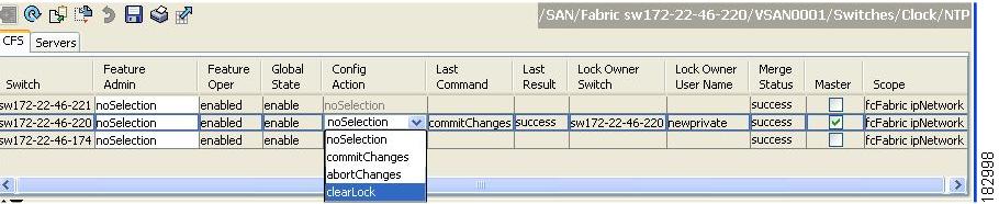
Clearing a Locked Session
You can clear locks held by an application from any switch in the fabric. This option is provided to rescue you from situations where locks are acquired and not released. This function requires Admin permissions.
To clear locks using Fabric Manager, follow these steps:
Step 1
Step 2
Step 3
Figure 13-1 Clearing Locks
Caution
CFS Merge Support
An application keeps the configuration synchronized in a fabric through CFS. Two such fabrics might merge as a result of an ISL coming up between them. These two fabrics could have two different sets of configuration information that need to be reconciled in the event of a merge. CFS provides notification each time an application peer comes online. If a fabric with M application peers merges with another fabric with N application peers and if an application triggers a merge action on every such notification, a link-up event results in M*N merges in the fabric.
CFS supports a protocol that reduces the number of merges required to one by handling the complexity of the merge at the CFS layer. This protocol runs per application per scope. The protocol involves selecting one switch in a fabric as the merge manager for that fabric. The other switches do not play any role in the merge process.
During a merge, the merge manager in the two fabrics exchange their configuration databases with each other. The application on one of them merges the information, decides if the merge is successful, and informs all switches in the combined fabric of the status of the merge.
In case of a successful merge, the merged database is distributed to all switches in the combined fabric and the entire new fabric remains in a consistent state. You can recover from a merge failure by starting a distribution from any of the switches in the new fabric. This distribution restores all peers in the fabric to the same configuration database.
Displaying CFS Configuration Information
To display the status of CFS distribution on the switch using Device Manager, follow these steps:
Step 1
You see the CFS dialog box. This dialog box displays the distribution status of each feature using CFS, which currently registered applications are using CFS, and the result of the last successful merge attempt.
Step 2
CFS Distribution over IP
You can configure CFS to distribute information over IP for networks containing switches that are not reachable over Fibre Channel. CFS distribution over IP supports the following features:
•
•
Note
•
Note
•
•
•
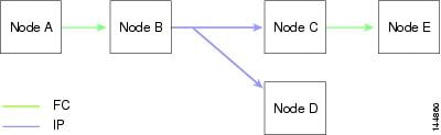
Figure 13-2 shows a network with both Fibre Channel and IP connections. Node A forwards an event to node B over Fibre Channel. Node B forwards the event node C and node D using unicast IP. Node C forwards the event to node E using Fibre Channel.
Figure 13-2 Network Example 1 with Fibre Channel and IP Connections
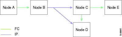
Figure 13-3 is the same as Figure 13-2 except that node D and node E are connected using Fibre Channel. All processes is the same in this example because node B has node C and node D the distribution list for IP. Node C does not forward to node D because node D is already in the distribution list from node B.
Figure 13-3 Network Example 2 with Fibre Channel and IP Connections
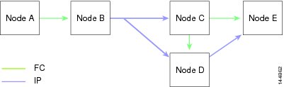
Figure 13-4 is the same as Figure 13-3 except that node D and node E are connected using IP. Both node C and node D forward the event to E because the node E is not in the distribution list from node B.
Figure 13-4 Network Example 3 with Fibre Channel and IP Connections
CFS Regions
This section contains the following topics:
•
•
•
•
About CFS Regions
A CFS region is a user-defined subset of switches for a given feature or application in its physical distribution scope.When a SAN is spanned across a vast geography, you may need to localize or restrict the distribution of certain profiles among a set of switches based on their physical proximity. Before release 3.2.(1) the distribution scope of an application within a SAN was spanned across the entire physical fabric without the ability to confine or limit the distribution to a required set of switches in the fabric. CFS regions enables you to overcome this limitation by allowing you to create CFS regions, that is, multiple islands of distribution within the fabric, for a given CFS feature or application. CFS regions are designed to restrict the distribution of a feature's configuration to a specific set or grouping of switches in a fabric.
Note
Example Scenario: The callhome is an application that triggers alerts to Network Administrators when a situation arises or something abnormal occurs. When the fabric covers many geographies and with multiple Network Administrators who are each responsible for a subset of switches in the fabric, the callhome application sends alerts to all Network Administrators regardless of their location. For the callhome application to send message alerts selectively to Network Administrators, the physical scope of the application has to be fine tuned or narrowed down, which is achieved by implementing CFS regions.
CFS regions are identified by numbers ranging from 0 through 200. Region 0 is reserved as the default region, and contains every switch in the fabric. You can configure regions from 1 through 200. The default region maintains backward compatibility. If there are switches on the same fabric running releases of SAN-OS before release 3.2(1), only features in Region 0 are supported when those switches are synchronized. Features from other regions are ignored when those switches are synchronized.
If the feature is moved, that is, assigned to a new region, its scope is restricted to that region; it ignores all other regions for distribution or merging purposes. The assignment of the region to a feature has precedence in distribution over its initial physical scope.
You can configure a CFS region to distribute configurations for multiple features. However, on a given switch, you can configure only one CFS region at a time to distribute the configuration for a given feature. Once you assign a feature to a CFS region, its configuration cannot be distributed within another CFS region.
Managing CFS Regions Using Fabric Manager
This section describes how to use Fabric Manager for managing CFS regions. Fabric Manager provides a comprehensive view of all the switches, regions, and the features associated with each region in the topology. To complete the following tasks, use the tables under the All Regions and Feature by Region tabs:
•
•
•
Creating CFS Regions
To create a CFS region using Fabric Manager, follow these steps:
Step 1
The information pane displays the Global, IP Multicast, Feature by Region, and All Regions tabs.
Step 2
The tab displays a list of Switches and RegionIds.
Step 3
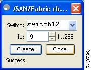
Figure 13-5 shows the Create a Region dialog box.
Figure 13-5 Create a Region Dialog Box
Step 4
Step 5
Upon successful creation of the region, Success is displayed at the bottom of the dialog box.
Assigning Features to CFS Regions
To assign a feature to a region using Fabric Manager, follow these steps:
Step 1
The information pane displays the Global, IP Multicast, Feature by Region, and All Regions tabs.
Step 2
This tab lists all the switches along with their corresponding Feature and RegionId.
Step 3
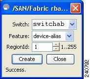
Figure 13-6 shows the Assign a Feature dialog box.
Figure 13-6 Assign a Feature Dialog Box
Step 4
The features running on the selected switch are listed in the Feature drop-down box.
Step 5
Step 6
Step 7
Upon successful assignment of feature, "Success" is displayed at the bottom of the dialog box.
When a feature is assigned to a new region using the Feature by Region tab, a new row with the new region is created automatically in the table under the All Regions tab. Alternatively, you can create a region using the All Regions tab.
Note
Moving a Feature to a Different Region
Before moving a feature to a new region, create the new region in the All Regions tab. That is, a new row has to be added in the All Regions tab with the new Region ID.
To move a feature to a different region using Fabric Manager, follow these steps:
Step 1
The information pane displays the Global, IP Multicast, Feature by Region, and All Regions tabs.
Step 2
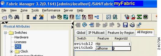
Figure 13-7 shows the Feature by Region tab, which lists all the switches along with their feature and region details.
Figure 13-7 Feature by Region Tab
Step 3
The cursor blinks in the cell prompting a change in the value.
Step 4
Step 5
Removing a Feature from a Region
To remove a feature from a region using Fabric Manager, follow these steps:
Step 1
Step 2
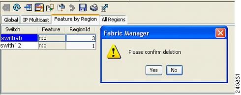
Figure 13-8 shows a confirmation dialog box.
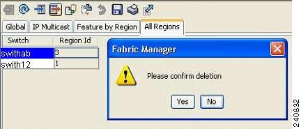
Figure 13-8 Removing a Feature from a Region
Step 3
Deleting CFS Regions
To delete an entire region, follow these steps:
Step 1
Step 2
This action removes all entries pertaining to that switch and region in the table under Feature by Region tab.
Figure 13-9 shows a confirmation dialog box.
Figure 13-9 Deleting CFS Regions
Step 3
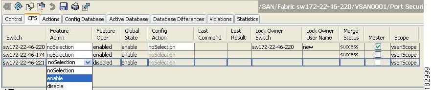
CFS Example Using Fabric Manager
This procedure is an example of what you see when you use Fabric Manager to configure a feature that uses CFS.
Step 1
You see the port security configuration for that VSAN in the Information pane.
Step 2
You see the CFS configuration and status for each switch (see Figure 13-10).
Figure 13-10 CFS Configuration
Step 3
Step 4
Note
Step 5
Step 6
Step 7
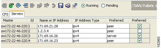
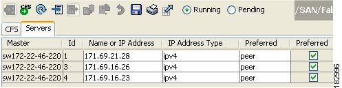
You see the configuration for this feature based on the master switch (see Figure 13-11).
Step 8
a.
b.
c.
Figure 13-11 Servers Tab
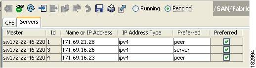
Step 9
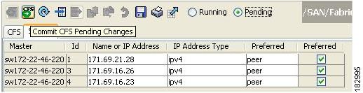
If you make any changes, the status automatically changes to Pending (see Figure 13-12).
Figure 13-12 Status Change to Pending
Step 10
Figure 13-13 Commit CFS Pending Changes
Step 11
Figure 13-14 Status Change to Running
Step 12
Figure 13-15 Commit Configuration Changes
Note
Step 13
Note
To configure the master or seed switch for distribution for each feature using Fabric Manager, follow these steps:
Step 1
The Information pane shows that feature including a CFS tab.
Step 2
Step 3
Step 4
CFS Example Using Device Manager
This procedure is an example of what you see when you use Device Manager to configure a feature that uses CFS. For specific procedures for features that use CFS, refer to that feature's documentation.
To configure a feature that uses CFS using Device Manager, follow these steps:
Step 1
Step 2
Step 3
Step 4
Step 5
Note
Step 6
You then see a dialog box for the feature. As soon as you perform a creation, deletion, or modification, Device Manager changes the status to "pending" and displays the updated information from the pending database.
Step 7
The Last Command and Result fields are blank if the last command is noOp.
Note
Default Settings
Table 13-1 lists the default settings for CFS configurations.