-
Cisco MDS 9000 Family Fabric Manager Configuration Guide, Release 3.x
-
Index
-
New and Changed Information
-
Preface
- Getting Started
- Installation and Switch Management
- Switch Configuration
-
Fabric Configuration
-
Configuring and Managing VSANs
-
SAN Device Virtualization
-
Creating Dynamic VSANs
-
Configuring Inter-VSAN Routing
-
Distributing Device Alias Services
-
Configuring and Managing Zones
-
Configuring Fibre Channel Routing Services and Protocols
-
Dense Wavelength Division Multiplexing
-
Managing FLOGI, Name Server, FDMI, and RSCN Databases
-
Discovering SCSI Targets
-
Configuring FICON
-
Advanced Features and Concepts
-
-
Security
-
Configuring FIPS
-
Configuring Users and Common Roles
-
Configuring SNMP
-
Configuring RADIUS and TACACS+
-
Configuring IPv4 Access Control Lists
-
Configuring Certificate Authorities and Digital Certificates
-
Configuring IPsec Network Security
-
Configuring FC-SP and DHCHAP
-
Configuring Port Security
-
Configuring Fabric Binding
-
- IP Services
- Intelligent Storage Services
- Network and Switch Monitoring
- Traffic Management
- Troubleshooting
-
Launching Fabric Manager in Cisco SAN-OS Releases Prior to 3.2(1)
-
Cisco Fabric Manager Unsupported Feature List
-
Interface Nonoperational Reason Codes
-
Managing Cisco FabricWare
-
Configuration Limits for Cisco MDS SAN-OS Release 3.1(x) and 3.2(x)
-
 Feedback
Table Of Contents
FCIP High-Availability Solutions
Ethernet PortChannels and Fibre Channel PortChannels
Verifying Interfaces and Extended Link Protocol
Launching Cisco Transport Controller
Launching Cisco Transport Controller
Advanced FCIP Profile Configuration
Advanced FCIP Interface Configuration
FCIP B Port Interoperability Mode
Configuring FCIP Write Acceleration
Configuring FCIP Tape Acceleration
Configuring FCIP
Cisco MDS 9000 Family IP storage (IPS) services extend the reach of Fibre Channel SANs by using open-standard, IP-based technology. The switch can connect separated SAN islands using Fibre Channel over IP (FCIP).
Note
FCIP is specific to the IPS module and is available in Cisco MDS 9200 Switches or Cisco MDS 9500 Directors.
The Cisco MDS 9216I switch and the 14/2 Multiprotocol Services (MPS-14/2) module also allow you to use Fibre Channel, FCIP, and iSCSI features. The MPS-14/2 module is available for use in any switch in the Cisco MDS 9200 Series or Cisco MDS 9500 Series.
Note
This chapter includes the following sections:
About FCIP
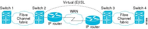
The Fibre Channel over IP Protocol (FCIP) is a tunneling protocol that connects geographically distributed Fibre Channel storage area networks (SAN islands) transparently over IP local area networks (LANs), metropolitan area networks (MANs), and wide area networks (WANs). See Figure 48-1.
Figure 48-1 Fibre Channel SANs Connected by FCIP
FCIP uses TCP as a network layer transport.
Note
This section includes the following topics:
•
•
FCIP Concepts
To configure IPS modules or MPS-14/2 modules for FCIP, you should have a basic understanding of the following concepts:
FCIP and VE Ports
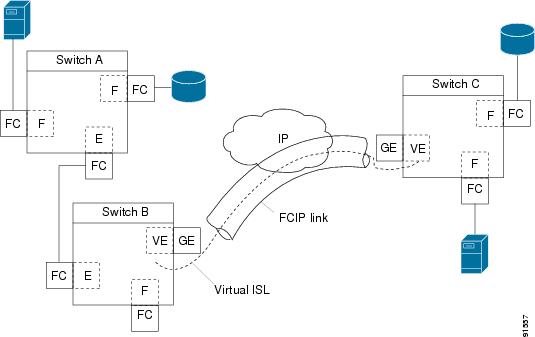
Figure 48-2 describes the internal model of FCIP with respect to Fibre Channel Inter-Switch Links (ISLs) and Cisco's extended ISLs (EISLs).
FCIP virtual E (VE) ports behave exactly like standard Fibre Channel E ports, except that the transport in this case is FCIP instead of Fibre Channel. The only requirement is for the other end of the VE port to be another VE port.
A virtual ISL is established over an FCIP link and transports Fibre Channel traffic. Each associated virtual ISL looks like a Fibre Channel ISL with either an E port or a TE port at each end (see Figure 48-2).
Figure 48-2 FCIP Links and Virtual ISLs
See the "Configuring E Ports" section.
FCIP Links
FCIP links consist of one or more TCP connections between two FCIP link endpoints. Each link carries encapsulated Fibre Channel frames.
When the FCIP link comes up, the VE ports at both ends of the FCIP link create a virtual Fibre Channel (E)ISL and initiate the E port protocol to bring up the (E)ISL.
By default, the FCIP feature on any Cisco MDS 9000 Family switch creates two TCP connections for each FCIP link:
•
•
To enable FCIP on the IPS module or MPS-14/2 module, an FCIP profile and FCIP interface (interface FCIP) must be configured.
The FCIP link is established between two peers, the VE port initialization behavior is identical to a normal E port. This behavior is independent of the link being FCIP or pure Fibre Channel, and is based on the E port discovery process (ELP, ESC).
Once the FCIP link is established, the VE port behavior is identical to E port behavior for all inter-switch communication (including domain management, zones, and VSANs). At the Fibre Channel layer, all VE and E port operations are identical.
FCIP Profiles
The FCIP profile contains information about the local IP address and TCP parameters. The profile defines the following information:
•
•
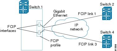
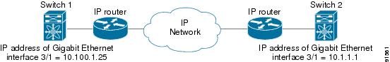
The FCIP profile's local IP address determines the Gigabit Ethernet port where the FCIP links terminate (see Figure 48-3).
Figure 48-3 FCIP Profile and FCIP Links
FCIP Interfaces
The FCIP interface is the local endpoint of the FCIP link and a VE port interface. All the FCIP and E port parameters are configured in context to the FCIP interface.
The FCIP parameters consist of the following:
•
•
•
•
FCIP High-Availability Solutions
The following high-availability solutions are available for FCIP configurations:
•
•
Fibre Channel PortChannels
Figure 48-4 provides an example of a PortChannel-based load-balancing configuration. To perform this configuration, you need two IP addresses on each SAN island. This solution addresses link failures.
Figure 48-4 PortChannel-Based Load Balancing
The following characteristics set Fibre Channel PortChannel solutions apart from other solutions:
•
•
•
FSPF
Figure 48-5 displays a FPSF-based load balancing configuration example. This configuration requires two IP addresses on each SAN island, and addresses IP and FCIP link failures.
Figure 48-5 FSPF-Based Load Balancing
The following characteristics set FSPF solutions apart from other solutions:
•
•
•
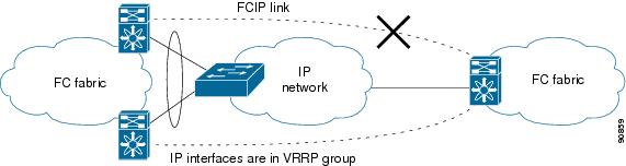
VRRP
Figure 48-6 displays a Virtual Router Redundancy Protocol (VRRP)-based high availability FCIP configuration example. This configuration requires at least two physical Gigabit Ethernet ports connected to the Ethernet switch on the island where you need to implement high availability using VRRP.
Figure 48-6 VRRP-Based High Availability
The following characteristics set VRRP solutions apart from other solutions:
•
•
•
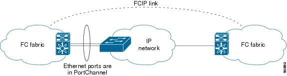
Ethernet PortChannels
Figure 48-7 displays an Ethernet PortChannel-based high- availability FCIP example. This solution addresses the problem caused by individual Gigabit Ethernet link failures.
Figure 48-7 Ethernet PortChannel-Based High Availability
The following characteristics set Ethernet PortChannel solutions apart from other solutions:
•
•
•
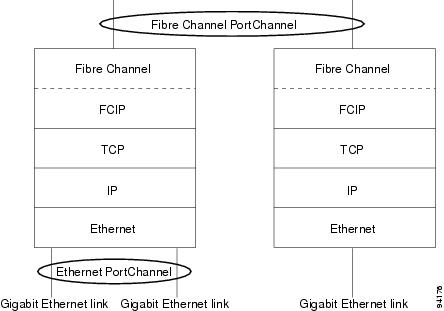
Ethernet PortChannels and Fibre Channel PortChannels
Ethernet PortChannels offer link redundancy between the Cisco MDS 9000 Family switch's Gigabit Ethernet ports and the connecting Ethernet switch. On the other hand, Fibre Channel PortChannels also offer (E)ISL link redundancy between Fibre Channel switches. FCIP is an (E)ISL link and is only applicable for a Fibre Channel PortChannel. Beneath the FCIP level, an FCIP link can run on top of an Ethernet PortChannel or just on one Gigabit Ethernet port. This link is totally transparent to the Fibre Channel layer.
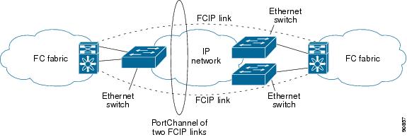
An Ethernet PortChannel restriction only allows two contiguous IPS ports, such as ports 1-2 or 3-4, to be combined in one Ethernet PortChannel (see the "Configuring Gigabit Ethernet High Availability" section on page 44-10). This restriction only applies to Ethernet PortChannels. The Fibre Channel PortChannel (to which FCIP link can be a part of) does not have a restriction on which (E)ISL links can be combined in a Fibre Channel PortChannel as long as it passes the compatibility check (see the "Compatibility Check" section on page 23-15). The maximum number of Fibre Channel ports that can be put into a Fibre Channel PortChannel is 16 (see Figure 48-8).
Figure 48-8 PortChannels at the Fibre Channel and Ethernet Levels
To configure Fibre Channel PortChannels, see Chapter 23, "Configuring PortChannels." To configure Ethernet PortChannels, see the "Configuring High Availability" section on page 17-1.
Configuring FCIP
This section describes how to configure FCIP and includes the following topics:
•
•
•
Enabling FCIP
To begin configuring the FCIP feature, you must explicitly enable FCIP on the required switches in the fabric. By default, this feature is disabled in all switches in the Cisco MDS 9000 Family.
The configuration and verification operations for the FCIP feature are only available when FCIP is enabled on a switch. When you disable this feature, all related configurations are automatically discarded.
To use the FCIP feature, you need to obtain the SAN extension over IP package license (SAN_EXTN_OVER_IP or SAN_EXTN_OVER_IP_IPS4) (see Chapter 10, "Obtaining and Installing Licenses").
Using the FCIP Wizard
Note
To create and manage FCIP links with Fabric Manager, use the FCIP Wizard. Firstly, make sure that the the IP services module is inserted in the required Cisco MDS 9000 Family switches, and the Gigabit Ethernet interfaces on these switches are connected and then the verify the connectivity. The steps in creating FCIP links using the FCIP Wizard:
•
•
•
•
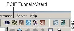
To create FCIP links using the FCIP Wizard, follow these steps:
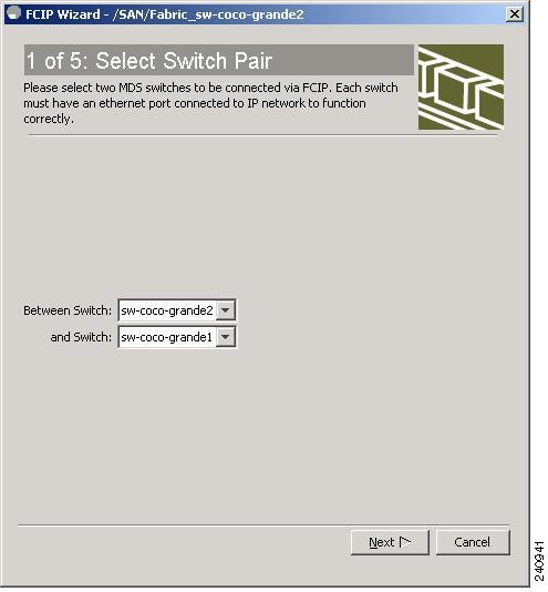
Step 1
Figure 48-9 FCIP Wizard
You see the switch selections as shown in Figure 48-10.
Figure 48-10 Switch Selections
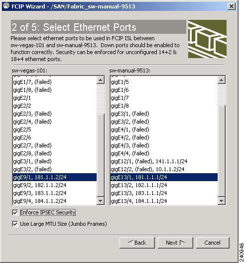
Step 2
Step 3
Step 4
Check the Use Large MTU Size (Jumbo Frames) option to use jumbo size frames of 2300. Since Fibre Channel frames are 2112, we recommended that you use this option. If you uncheck the box, the FCIP Wizard does not set the MTU size, and the default value of 1500 is set.
Note
Figure 48-11 Enabling IPsec on an FCIP link
Step 5
You see the IP Address/Route input screen.
Step 6
Figure 48-12 Specify IP Address/Route
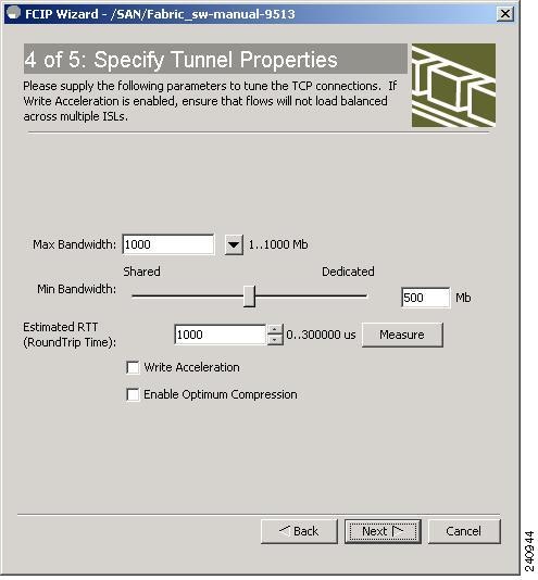
Step 7
Step 8
Figure 48-13 Specifying Tunnel Properties
Step 9
See the "FCIP Write Acceleration" section.
Step 10
See the "FCIP Compression" section.
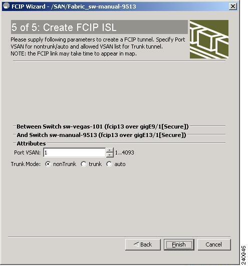
Step 11
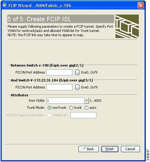
Step 12
Note
Figure 48-14 Create FCIP ISL
Figure 48-15
Enter FICON Port Address
Figure 48-16 Create FCIP ISL
Figure 48-17
Enter FICON Port Address
Step 13
Basic FCIP Configuration
Once you have created FCIP links using the FCIP wizard, you may need to modify parameters for these links. This includes modifying the FCIP profiles as well as the FCIP link parameters. Each Gigabit Ethernet interface can have three active FCIP links at one time.
Once you have created FCIP links using the FCIP wizard, you may need to modify parameters for these links. This includes modifying the FCIP profiles as well as the FCIP link parameters. Each Gigabit Ethernet interface can have three active FCIP links at one time.
To configure an FCIP link, follow these steps on both switches:
Step 1
Step 2
Step 3
Step 4
Step 5
Creating FCIP Profiles
You must assign a local IP address of a Gigabit Ethernet interface or subinterface to the FCIP profile to create an FCIP profile. You can assign IPv4 or IPv6 addresses to the interfaces. Figure 48-18 shows an example configuration.
Figure 48-18 Assigning Profiles to Each Gigabit Ethernet Interface
To create an FCIP profile in switch 1, follow these steps:
Step 1
Step 2
Step 3
Step 4
Step 5
Step 6
Step 7
Step 8
Step 9
Creating FCIP Links
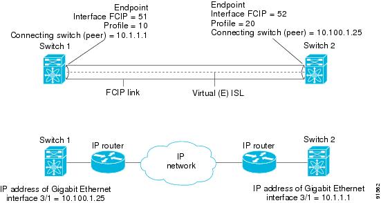
When two FCIP link endpoints are created, an FCIP link is established between the two IPS modules or MPS-14/2 modules. To create an FCIP link, assign a profile to the FCIP interface and configure the peer information. The peer IP switch information initiates (creates) an FCIP link to that peer switch (see Figure 48-19).
Figure 48-19 Assigning Profiles to Each Gigabit Ethernet Interface
Verifying Interfaces and Extended Link Protocol
To verify the FCIP interfaces and Extended Link Protocol (ELP) on Device Manager, follow these steps:
Step 1
Step 2
Step 3
Step 4
Checking Trunk Status
To check the trunk status for the FCIP interface on Device Manager, follow these steps:
Step 1
Step 2
Step 3
Step 4
Launching Cisco Transport Controller
Cisco Transport Controller (CTC) is a task-oriented tool used to install, provision, and maintain network elements. It is also used to troubleshoot and repair NE faults.
To launch CTC using Fabric Manager, follow these steps:
Step 1
Step 2
Step 3
Step 4
Launching Cisco Transport Controller
Cisco Transport Controller (CTC) is a task-oriented tool used to install, provision, and maintain network elements. It is also used to troubleshoot and repair NE faults.
To launch CTC using Fabric Manager, follow these steps:
Step 1
Step 2
Step 3
Step 4
Advanced FCIP Profile Configuration
A basic FCIP configuration uses the local IP address to configure the FCIP profile. In addition to the local IP address and the local port, you can specify other TCP parameters as part of the FCIP profile configuration.
Configuring TCP Parameters
You can control TCP behavior in a switch by configuring the following TCP parameters.
Note
This section includes the following topics:
Minimum Retransmit Timeout
You can control the minimum amount of time TCP waits before retransmitting. By default, this value is 200 milliseconds (msec).
Keepalive Timeout
You can configure the interval that the TCP connection uses to verify that the FCIP link is functioning. This ensures that an FCIP link failure is detected quickly even when there is no traffic.
If the TCP connection is idle for more than the specified time, then keepalive timeout packets are sent to ensure that the connection is active. The keepalive timeout feature can be used to tune the time taken to detect FCIP link failures.
You can configure the first interval during which the connection is idle (the default is 60 seconds). When the connection is idle for the configured interval, eight keepalive probes are sent at 1-second intervals. If no response is received for these eight probes and the connection remains idle throughout, that FCIP link is automatically closed.
Note
Maximum Retransmissions
You can specify the maximum number of times a packet is retransmitted before TCP decides to close the connection.
Path MTUs
Path MTU (PMTU) is the minimum MTU on the IP network between the two endpoints of the FCIP link. PMTU discovery is a mechanism by which TCP learns of the PMTU dynamically and adjusts the maximum TCP segment accordingly (RFC 1191).
By default, PMTU discovery is enabled on all switches with a timeout of 3600 seconds. If TCP reduces the size of the maximum segment because of PMTU change, the reset-timeout specifies the time after which TCP tries the original MTU.
Selective Acknowledgments
TCP may experience poor performance when multiple packets are lost within one window. With the limited information available from cumulative acknowledgments, a TCP sender can only learn about a single lost packet per round trip. A selective acknowledgment (SACK) mechanism helps overcome the limitations of multiple lost packets during a TCP transmission.
The receiving TCP sends back SACK advertisements to the sender. The sender can then retransmit only the missing data segments. By default, SACK is enabled on Cisco MDS 9000 Family switches.
Window Management
The optimal TCP window size is automatically calculated using the maximum bandwidth parameter, the minimum available bandwidth parameter, and the dynamically measured round trip time (RTT).
Note
The min-available-bandwidth parameter and the measured RTT together determine the threshold below which TCP aggressively maintains a window size sufficient to transmit at minimum available bandwidth.
The max-bandwidth-mbps parameter and the measured RTT together determine the maximum window size.
Note
Monitoring Congestion
By enabling the congestion window monitoring (CWM) parameter, you allow TCP to monitor congestion after each idle period. The CWM parameter also determines the maximum burst size allowed after an idle period. By default, this parameter is enabled and the default burst size is 50 KB.
The interaction of bandwidth parameters and CWM and the resulting TCP behavior is outlined as follows:
•
•
•
The software uses standard TCP rules to increase the window beyond the one required to maintain the min-available-bandwidth to reach the max-bandwidth.
Note
Tip
Estimating Maximum Jitter
Jitter is defined as a variation in the delay of received packets. At the sending side, packets are sent in a continuous stream with the packets spaced evenly apart. Due to network congestion, improper queuing, or configuration errors, this steady stream can become lumpy, or the delay between each packet can vary instead of remaining constant.
You can configure the maximum estimated jitter in microseconds by the packet sender. The estimated variation should not include network queuing delay. By default, this parameter is enabled in Cisco MDS switches when IPS modules or MPS-14/2 modules are present.
The default value is 1000 microseconds for FCIP interfaces.
Buffer Size
You can define the required additional buffering—beyond the normal send window size —that TCP allows before flow controlling the switch's egress path for the FCIP interface. The default FCIP buffer size is 0 KB.
Note
Advanced FCIP Interface Configuration
This section describes the options you can configure on an FCIP interface to establish connection to a peer and includes the following topics:
•
To establish a peer connection, you must first create the FCIP interface .
Configuring Peers
To establish an FCIP link with the peer, you can use one of two options:
•
•
Peer IP Address
The basic FCIP configuration uses the peer's IP address to configure the peer information. You can also specify the peer's port number to configure the peer information. If you do not specify a port, the default 3225 port number is used to establish connection. You can specify an IPv4 address or an IPv6 address.
To assign the peer information based on the IPv4 address and port number using Fabric Manager, follow these steps:
Step 1
You see the FCIP profiles and links in the Information pane.
From Device manager, choose IP > FCIP.
You see the FCIP dialog box.
Step 2
Step 3
You see the FCIP Tunnels dialog box.
Step 4
Step 5
Step 6
Step 7
Step 8
Step 9
To assign the peer information based on the IPv6 address and port number using Fabric Manager, follow these steps:
Step 1
You see the FCIP profiles and links in the Information pane.
From Device manager, choose IP > FCIP.You see the FCIP dialog box.
Step 2
Step 3
You see the FCIP Tunnels dialog box.
Step 4
Step 5
Step 6
Step 7
Step 8
Step 9
Special Frames
You can alternatively establish an FCIP link with a peer using an optional protocol called special frames. When special frames are enabled, the peer IP address (and optionally the port or the profile ID) only needs to be configured on one end of the link. Once the connection is established, a special frame is exchanged to discover and authenticate the link.
By default, the special frame feature is disabled. You must enable special frames on the interfaces on both peers to establish the FCIP link.
Note
Tip
To enable special frames using Fabric Manager, follow these steps:
Step 1
You see the FCIP profiles and links in the Information pane.
From Device manager, choose IP > FCIP.You see the FCIP dialog box.
Step 2
Step 3
You see the FCIP Tunnels dialog box.
Step 4
Step 5
Step 6
Step 7
Step 8
Step 9
Active Connections
You can configure the required mode for initiating a TCP connection. By default, active mode is enabled to actively attempt an IP connection. If you enable the passive mode, the switch does not initiate a TCP connection rather waits for the peer to connect to it.
Note
Number of TCP Connections
You can specify the number of TCP connections from an FCIP link. By default, the switch tries two (2) TCP connections for each FCIP link. You can configure one or two TCP connections. For example, the Cisco PA-FC-1G Fibre Channel port adapter, which has only one (1) TCP connection, interoperates with any switch in the Cisco MDS 9000 Family. One TCP connection is within the specified limit. If the peer initiates one TCP connection, and your MDS switch is configured for two TCP connections, then the software handles it and proceeds with just one connection.
Time Stamp Control
You can instruct the switch to discard packets that are outside the specified time. When enabled, this feature specifies the time range within which packets can be accepted. If the packet arrived within the range specified by this option, the packet is accepted. Otherwise, it is dropped.
By default, time stamp control is disabled in all switches in the Cisco MDS 9000 Family. If a packet arrives within a 2000 millisecond interval (+ or -2000 msec) from the network time, that packet is accepted.
Note
If the time-stamp option is enabled, be sure to configure NTP on both switches (see the "NTP Configuration" section on page 12-21).
Tip
FCIP B Port Interoperability Mode
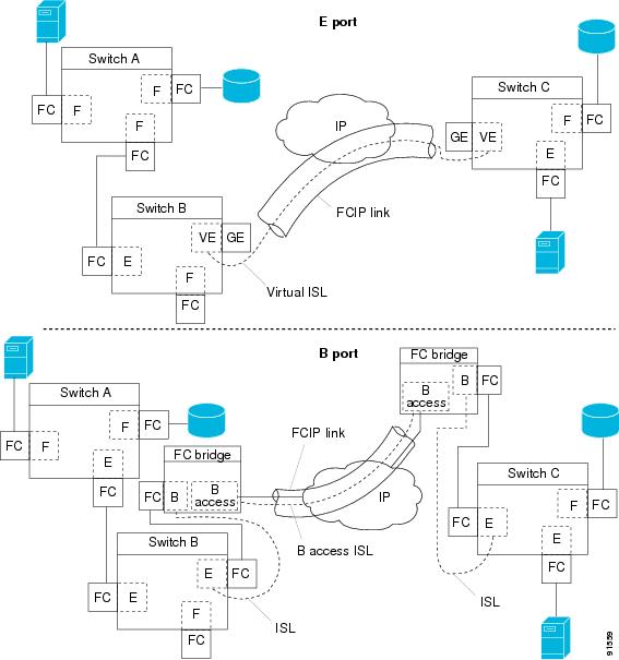
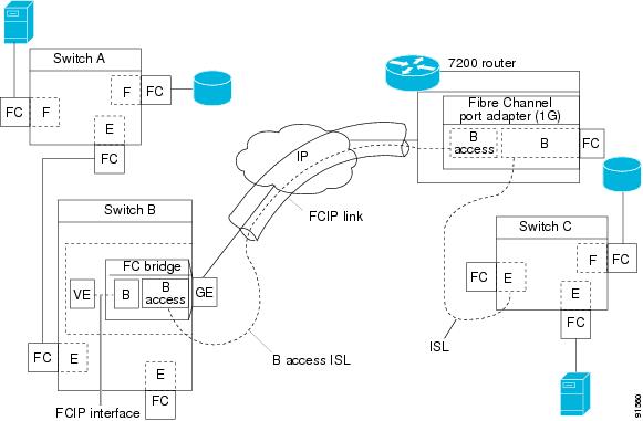
While E ports typically interconnect Fibre Channel switches, some SAN extender devices, such as Cisco's PA-FC-1G Fibre Channel port adapter and the SN 5428-2 storage router, implement a bridge port model to connect geographically dispersed fabrics. This model uses B port as described in the T11 Standard FC-BB-2. Figure 48-20 shows a typical SAN extension over an IP network.
Figure 48-20 FCIP B Port and Fibre Channel E Port
B ports bridge Fibre Channel traffic from a local E port to a remote E port without participating in fabric-related activities such as principal switch election, domain ID assignment, and Fibre Channel fabric shortest path first (FSPF) routing. For example, Class F traffic entering a SAN extender does not interact with the B port. The traffic is transparently propagated (bridged) over a WAN interface before exiting the remote B port. This bridge results in both E ports exchanging Class F information that ultimately leads to normal ISL behavior such as fabric merging and routing.
FCIP links between B port SAN extenders do not exchange the same information as FCIP links between E ports, and are therefore incompatible. This is reflected by the terminology used in FC-BB-2: while VE ports establish a virtual ISL over an FCIP link, B ports use a B access ISL.
The IPS module and MPS-14/2 module support FCIP links that originate from a B port SAN extender device by implementing the B access ISL protocol on a Gigabit Ethernet interface. Internally, the corresponding virtual B port connects to a virtual E port that completes the end-to-end E port connectivity requirement (see Figure 48-21).
Figure 48-21 FCIP Link Terminating in a B Port Mode
The B port feature in the IPS module and MPS-14/2 module allows remote B port SAN extenders to communicate directly with a Cisco MDS 9000 Family switch, eliminating the need for local bridge devices.
Configuring B Ports
When an FCIP peer is a SAN extender device that only supports Fibre Channel B ports, you need to enable the B port mode for the FCIP link. When a B port is enabled, the E port functionality is also enabled and they coexist. If the B port is disabled, the E port functionality remains enabled.
To enable B port mode using Fabric Manager, follow these steps:
Step 1
You see the FCIP profiles and links in the Information pane.
From Device manager, choose IP > FCIP. You see the FCIP dialog box.
Step 2
You see the FCIP link information.
Step 3
You see the FCIP Tunnels dialog box.
Step 4
Step 5
Step 6
Step 7
Step 8
Step 9
Quality of Service
The quality of service (QoS) parameter specifies the differentiated services code point (DSCP) value to mark all IP packets (type of service—TOS field in the IP header).
•
•
If the FCIP link has only one TCP connection, that data DSCP value is applied to all packets in that connection.
Configuring E Ports
•
•
•
–
–
•
•
•
Advanced FCIP Features
You can significantly improve application performance by configuring one or more of the following options for the FCIP interface.
•
•
FCIP Write Acceleration
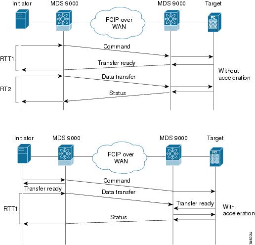
The FCIP write acceleration feature enables you to significantly improve application write performance when storage traffic is routed over wide area networks using FCIP. When FCIP write acceleration is enabled, WAN throughput is maximized by minimizing the impact of WAN latency for write operations.
Note
In Figure 48-22, the WRITE command without write acceleration requires two round trip transfers (RTT), while the WRITE command with write acceleration only requires one RTT. The maximum sized Transfer Ready is sent from the host side of the FCIP link back to the host before the WRITE command reaches the target. This enables the host to start sending the write data without waiting for the long latency over the FCIP link of the WRITE command and Transfer Ready. It also eliminates the delay caused by multiple Transfer Readys needed for the exchange going over the FCIP link.
Figure 48-22 FCIP Link Write Acceleration
Tip
Tip
Note
Caution
Configuring FCIP Write Acceleration
You can enable FCIP write acceleration when you create the FCIP link using the FCIP Wizard.
You can enable FCIP write acceleration when you create the FCIP link using the FCIP Wizard.
To enable write acceleration on an existing FCIP link, follow these steps:
Step 1
You see the FCIP profiles and links in the Information pane.
On Device manager, choose IP > FCIP.
You see the FCIP dialog box.
Step 2
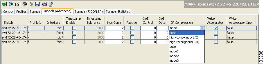
You see the FICP link information (see Figure 48-23).
Figure 48-23 FCIP Tunnels (Advanced) Tab
Step 3
Step 4
Step 5
Step 1
You see the FCIP profiles and links in the Information pane.
On Device manager, choose IP > FCIP.
You see the FCIP dialog box.
Step 2
You see the FICP link information (see Figure 48-23).
Figure 48-24 FCIP Tunnels (Advanced) Tab
Step 3
Step 4
Step 5
FCIP Tape Acceleration
Tapes are storage devices that store and retrieve user data sequentially. Cisco MDS SAN-OS provides both tape write and read acceleration.
Applications that access tape drives normally have only one SCSI WRITE or READ operation outstanding to it. This single command process limits the benefit of the tape acceleration feature when using an FCIP tunnel over a long-distance WAN link. It impacts backup, restore, and restore performance because each SCSI WRITE or READ operation does not complete until the host receives a good status response from the tape drive. The FCIP tape acceleration feature helps solve this problem. It improves tape backup, archive, and restore operations by allowing faster data streaming between the host and tape drive over the WAN link.
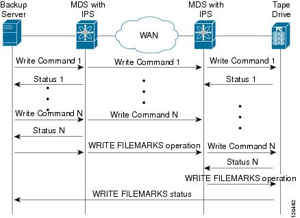
In an example of tape acceleration for write operations, the backup server in Figure 48-25 issues write operations to a drive in the tape library. Acting as a proxy for the remote tape drives, the local Cisco MDS switch proxies a transfer ready to signal the host to start sending data. After receiving all the data, the local Cisco MDS switch proxies the successful completion of the SCSI WRITE operation. This response allows the host to start the next SCSI WRITE operation. This proxy method results in more data being sent over the FCIP tunnel in the same time period compared to the time taken to send data without proxying. The proxy method improves the performance on WAN links.
Figure 48-25 FCIP Link Tape Acceleration for Write Operations
At the tape end of the FCIP tunnel, another Cisco MDS switch buffers the command and data it has received. It then acts as a backup server to the tape drive by listening to a transfer ready from the tape drive before forwarding the data.
Note
The Cisco SAN-OS provides reliable data delivery to the remote tape drives using TCP/IP over the WAN. It maintains write data integrity by allowing the WRITE FILEMARKS operation to complete end-to-end without proxying. The WRITE FILEMARKS operation signals the synchronization of the buffer data with the tape library data. While tape media errors are returned to backup servers for error handling, tape busy errors are retried automatically by the Cisco SAN-OS software.
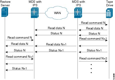
In an example of tape acceleration for read operations, the restore server in Figure 48-26 issues read operations to a drive in the tape library. During the restore process, the remote Cisco MDS switch at the tape end, in anticipation of more SCSI read operations from the host, sends out SCSI read operations on its own to the tape drive. The prefetched read data is cached at the local Cisco MDS switch. The local Cisco MDS switch on receiving SCSI read operations from the host, sends out the cached data. This method results in more data being sent over the FCIP tunnel in the same time period compared to the time taken to send data without read acceleration for tapes. This improves the performance for tape reads on WAN links.
Figure 48-26 FCIP Link Tape Acceleration for Read Operations
The Cisco SAN-OS provides reliable data delivery to the restore application using TCP/IP over the WAN. While tape media errors during the read operation are returned to the restore server for error handling, the Cisco SAN-OS software recovers from any other errors.
Note
Tip
Caution
Note
In tape acceleration for writes, after a certain amount of data has been buffered at the remote Cisco MDS switch, the write operations from the host are flow controlled by the local Cisco MDS switch by not proxying the Transfer Ready. On completion of a write operation when some data buffers are freed, the local Cisco MDS switch resumes the proxying. Likewise, in tape acceleration for reads, after a certain amount of data has been buffered at the local Cisco MDS switch, the read operations to the tape drive are flow controlled by the remote Cisco MDS switch by not issuing any further reads. On completion of a read operation, when some data buffers are freed, the remote Cisco MDS switch resumes issuing reads.
The default flow control buffering uses the automatic option. This option takes the WAN latencies and the speed of the tape into account to provide optimum performance. You can also specify a flow control buffer size (the maximum buffer size is 12 MB).
Tip
Tip
Note
Tape Library LUN Mapping for FCIP Tape Acceleration
If a tape library provides logical unit (LU) mapping and FCIP tape acceleration is enabled, you must assign a unique LU number (LUN) to each physical tape drive accessible through a target port.
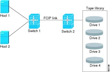
Figure 48-27 shows tape drives connected to Switch 2 through a single target port. If the tape library provides LUN mapping, then all the four tape drives should be assign unique LUNs.
Figure 48-27 FCIP LUN Mapping Example
For the mappings described in Table 48-1 and Table 48-2, Host 1 has access to Drive 1 and Drive 2, and Host 2 has access to Drive 3 and Drive 4.
Table 48-1 describes correct tape library LUN mapping.
Table 48-1 Correct LUN Mapping Example with Single Host Access
Host 1
LUN 1
Drive 1
LUN 2
Drive 2
Host 2
LUN 3
Drive 3
LUN 4
Drive 4
Table 48-2 describes incorrect tape library LUN mapping.
Table 48-2 Incorrect LUN Mapping Example with Single Hosts Access
Host 1
LUN 1
Drive 1
LUN 2
Drive 2
Host 2
LUN 1
Drive 3
LUN 2
Drive 4
Another example setup is when a tape drive is shared by multiple hosts through a single tape port. For instance, Host 1 has access to Drive1 and Drive2, and Host 2 has access to Drive 2, Drive 3, and Drive 4. A correct LUN mapping configuration for such a setup is shown in Table 48-3.
Table 48-3 Correct LUN Mapping Example with Multiple Host Access
Host 1
LUN 1
Drive 1
LUN 2
Drive 2
Host 2
LUN 2
Drive 2
LUN 3
Drive 3
LUN 4
Drive 4
Configuring FCIP Tape Acceleration
To enable FCIP tape acceleration using Fabric Manager, follow these steps:
Step 1
You see the FCIP profiles and links in the Information pane.
From Device Manager, choose IP > FCIP.
You see the FCIP dialog box.
Step 2
Step 3
You see the FCIP Tunnels dialog box.
Step 4
Step 5
Step 6
Step 7
To enable FCIP tape acceleration using Fabric Manager, follow these steps:
Step 1
You see the FCIP profiles and links in the Information pane.
From Device Manager, choose IP > FCIP.
You see the FCIP dialog box.
Step 2
Step 3
You see the FCIP Tunnels dialog box.
Step 4
Step 5
Step 6
Step 7
FCIP Compression
The FCIP compression feature allows IP packets to be compressed on the FCIP link if this feature is enabled on that link. By default the FCIP compression is disabled. When enabled, the software defaults to using the auto mode (if a mode is not specified).
Note
Table 48-4 lists the modes used for different cards.
Table 48-4 Algorithm Classification
mode1
SW
HW
SW
mode2
SW
SW
HW
mode3
SW
SW
SW
Table 48-5 Performance Settings
>25Mbps
mode1
mode1
mode2/mode3
10-25Mbps
mode2
mode2
mode2/mode3
10Mbps
mode3
mode3
mode2/mode3
Table 48-5 lists the performance settings for different cards.
Note
Caution
Tip
If both ends of the FCIP link are running Cisco SAN-OS Release 2.0(1b) or later and you enable compression at one end of the FCIP tunnel, be sure to enable it at the other end of the link.
Default Settings
Table 48-4 lists the default settings for FCIP parameters.