-
Cisco MDS 9000 Family Fabric Manager Configuration Guide, Release 3.x
-
Index
-
New and Changed Information
-
Preface
- Getting Started
- Installation and Switch Management
- Switch Configuration
-
Fabric Configuration
-
Configuring and Managing VSANs
-
SAN Device Virtualization
-
Creating Dynamic VSANs
-
Configuring Inter-VSAN Routing
-
Distributing Device Alias Services
-
Configuring and Managing Zones
-
Configuring Fibre Channel Routing Services and Protocols
-
Dense Wavelength Division Multiplexing
-
Managing FLOGI, Name Server, FDMI, and RSCN Databases
-
Discovering SCSI Targets
-
Configuring FICON
-
Advanced Features and Concepts
-
-
Security
-
Configuring FIPS
-
Configuring Users and Common Roles
-
Configuring SNMP
-
Configuring RADIUS and TACACS+
-
Configuring IPv4 Access Control Lists
-
Configuring Certificate Authorities and Digital Certificates
-
Configuring IPsec Network Security
-
Configuring FC-SP and DHCHAP
-
Configuring Port Security
-
Configuring Fabric Binding
-
- IP Services
- Intelligent Storage Services
- Network and Switch Monitoring
- Traffic Management
- Troubleshooting
-
Launching Fabric Manager in Cisco SAN-OS Releases Prior to 3.2(1)
-
Cisco Fabric Manager Unsupported Feature List
-
Interface Nonoperational Reason Codes
-
Managing Cisco FabricWare
-
Configuration Limits for Cisco MDS SAN-OS Release 3.1(x) and 3.2(x)
-
 Feedback
Table Of Contents
Configuring Date, Time, and Time Zone
Edit an NTP Server or Peer Configuration
Committing NTP Configuration Changes
Discarding NTP Configuration Changes
Management Interface Configuration
Initial Configuration
Most of the initial switch configuration procedures can only be performed using the CLI. Refer to the Cisco MDS 9000 Family CLI Configuration Guide for this information. This chapter includes the following sections:
•
Assigning a Switch Name, page 12-1
•
•
•
•
Note
Also note that you should not bring up the loader> prompt; the only way to fix this condition is to RMA the switch.
The following commands are not allowed on the Cisco Fabric Switch for IBM BladeCenter: write erase boot and init system; nor can you boot variables manually.
Assigning a Switch Name
Each switch in the fabric requires a unique name. You can assign names to easily identify the switch by its physical location, its SAN association, or the organization to which it is deployed. The assigned name is displayed in the command-line prompt. The switch name is limited to 20 alphanumeric characters.
To change the name of a switch using Fabric Manager, follow these steps:
Step 1
Step 2
You see a list of switches in the Information pane.
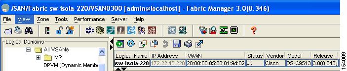
Step 3
You see the name highlighted with a blinking cursor next to it.
Figure 12-1 Changing the Logical Name of a Switch
Step 4
Step 5
Step 6
Verifying the Module Status
Before you begin configuring the switch, you need to ensure that the modules in the chassis are functioning as designed.
To verify the status of a module at any time, follow these steps:
Step 1
Step 2
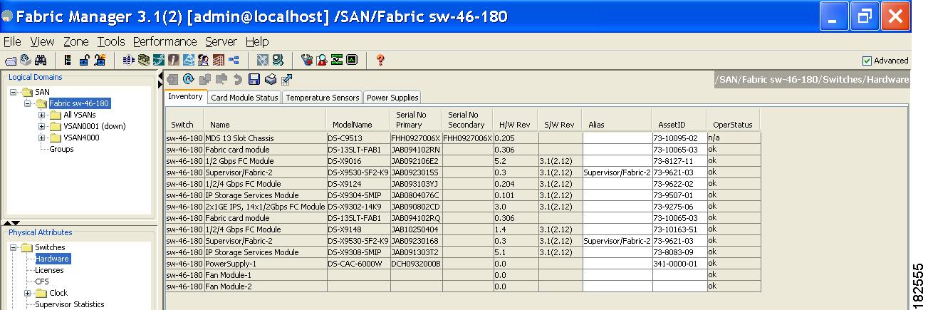
You see the contents of the Inventory tab in the Information pane shown in Figure 12-2.
Figure 12-2 Inventory of a Selected Module
Step 3
You see the status in the Oper Status column of each module in each switch of the SAN, fabric, or VSAN you selected.
If the status is OK or active, you can continue with your configuration (see Chapter 19, "Managing Modules").
Configuring Date, Time, and Time Zone
Switches in the Cisco MDS 9000 Family use Universal Coordinated Time (UTC), which is the same as Greenwich Mean Time (GMT).
To change the default time on the switch with Fabric Manager, follow these steps:
Step 1
You see a list of switches in the Information pane.
Step 2
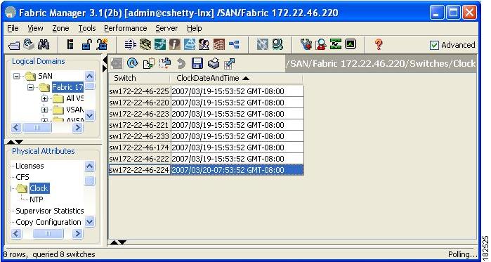
You see the clock information in the Information pane shown in Figure 12-3.
Figure 12-3 Clock Date and Time for Selected Switch
Step 3
Step 4
Where:
•
•
•
•
•
•
•
Note
Step 5
Note
Note
If you want to configure daylight savings time on multiple switches simultaneously, see the RUN CLI command feature in the Cisco MDS 9000 Family Fabric Manager Configuration Guide.
NTP Configuration
A Network Time Protocol (NTP) server provides a precise time source (radio clock or atomic clock) to synchronize the system clocks of network devices. NTP is transported over User Datagram Protocol UDP/IP. All NTP communications use Universal Time Coordinated (UTC). An NTP server receives its time from a reference time source, such as a radio clock or atomic clock, attached to the time. NTP distributes this time across the network.
This section includes the following sections:
•
•
•
•
About NTP
In a large enterprise network, having one time standard for all network devices is critical for management reporting and event logging functions when trying to correlate interacting events logged across multiple devices. Many enterprise customers with extremely mission-critical networks maintain their own stratum-1 NTP source.
Time synchronization happens when several frames are exchanged between clients and servers. The switches in client mode know the address of one or more NTP servers. The servers act as the time source and receive client synchronization requests.
By configuring an IP address as a peer, the switch will obtain and provide time as required. The peer is capable of providing time on its own and is capable of having a server configured. If both these instances point to different time servers, your NTP service is more reliable. Thus, even if the active server link is lost, you can still maintain the right time due to the presence of the peer.
Tip
If you only configure a peer, the most accurate peer takes on the role of the NTP server and the other peer(s) acts as a peer(s). Both machines end at the right time if they have the right time source or if they point to the right NTP source.
NTP Configuration Guidelines
The following guidelines apply to all NTP configurations:
•
•
•
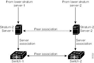
Not even a server down time will affect well-configured switches in the network. Figure 12-4 displays a network with two NTP stratum 2 servers and two switches.
Figure 12-4 NTP Peer and Server Association
In this configuration, the switches were configured as follows:
•
–
•
–
•
•
–
–
•
•
–
–
Configuring NTP
You can configure NTP using either IPv4 addresses, IPv6 addresses, or DNS names.
To create an NTP server or peer, follow these steps:
Step 1
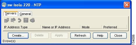
In Fabric Manager, you see the System information pane. In Device Manager, you see the NTP dialog box (see Figure 12-5).
Figure 12-5 Device Manager NTP Dialog Box
Step 2
You see a list of NTP peers and servers for that switch.
Step 3
You see the Create NTP Peer dialog box.
Step 4
Step 5
Step 6
Step 7
The new peer or server is listed on the Peer tab.
Edit an NTP Server or Peer Configuration
To edit an NTP server or peer, follow these steps.
Step 1
In Fabric Manager, you see the System information pane. In Device Manager, you see the NTP dialog box.
Step 2
You see a list of NTP peers and servers for that switch.
Step 3
Step 4
You see a drop-down list. Select the mode (peer or server) you want for the switch.
Step 5
Step 6
Delete an NTP Server or Peer
To delete an NTP server or peer, follow these steps.
Step 1
In Fabric Manager, you see the System information pane. In Device Manager, you see the NTP dialog box.
Step 2
You see a list of NTP peers and servers for that switch.
Step 3
Step 4
NTP CFS Distribution
You can enable NTP fabric distribution for all Cisco MDS switches in the fabric. When you perform NTP configurations, and distribution is enabled, the entire server/peer configuration is distributed to all the switches in the fabric.
You automatically acquire a fabric-wide lock when you issue the first configuration command after you enabled distribution in a switch. The NTP application uses the effective and pending database model to store or commit the commands based on your configuration.
See to Chapter 13, "Using the CFS Infrastructure," for more information on the CFS application.
This section includes the following sections:
•
•
•
•
Configure NTP with CFS
To configure NTP with CFS using Fabric Manager, follow these steps:
Step 1
You see the feature configuration in the Information pane.
Step 2
You see the CFS configuration and status for each switch.
Step 3
A drop-down menu appears (see Figure 12-6).
Figure 12-6 Enabling or Disabling NTP with CFS for a Switch
Step 4
Step 5
Note
Step 6
Step 7
Step 8
Step 9
Step 10
a.
b.
c.
Fabric Manager sends the request to the master switch. Click the CFS tab and check the Last Results column for the new entry. It has a "pending" status.Step 11
Note
Step 12
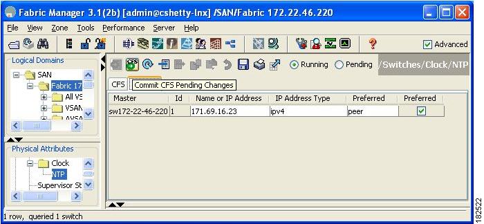
Committing NTP Configuration Changes
When you commit the NTP configuration changes, the effective database is overwritten by the configuration changes in the pending database and all the switches in the fabric receive the same configuration. When you commit the NTP configuration changes without implementing the session feature, the NTP configurations are distributed to all the switches in the fabric.
Discarding NTP Configuration Changes
After making the configuration changes, you can choose to discard the changes or to commit them. In either case, the lock is released.
Releasing Fabric Session Lock
If you have performed an NTP fabric task and have forgotten to release the lock by either committing or discarding the changes, an administrator can release the lock from any switch in the fabric. If the administrator performs this task, your changes to the pending database are discarded and the fabric lock is released.
Tip
Database Merge Guidelines
When merging two fabrics, follow these guidelines:
•
•
•
See to the "CFS Merge Support" section on page 13-9 for detailed concepts.
Management Interface Configuration
The management interface on the switch allows multiple simultaneous Telnet or SNMP sessions. You can remotely configure the switch through the management interface (mgmt0), but first you must configure some IP parameters so that the switch is reachable. You can manually configure the management interface from the CLI. You can configure the mgmt 0 interface with either IPv4 address parameters or an IPv6 address.
On director class switches, a single IP address is used to manage the switch. The active supervisor module's mgmt0 interface uses this IP address. The mgmt0 interface on the standby supervisor module remains in an inactive state and cannot be accessed until a switchover happens. After a switchover, the mgmt0 interface on the standby supervisor module becomes active and assumes the same IP address as the previously active supervisor module.
The management port (mgmt0) is autosensing and operates in full duplex mode at a speed of 10/100/1000 Mbps (1000 Mbps is only available on the Supervisor-2 module). Autosensing supports both the speed and the duplex mode. On a Supervisor-1 module, the default speed is 100 Mbps and the default duplex mode is auto. On a Supervisor-2 module, the default speed is auto and the default duplex mode is auto.
You can set the management interface in the Fabric Manager Preferences screen to use SNMP over TCP. The advantages of this setting are an increased buffer size and faster transfer rate. If your fabric has a long timeout period, it may prevent you from using SNMP (which may have a relatively shorter timeout period). If so, change this setting to false and restart Fabric Manager Server. UDP is used instead.
Note
Note
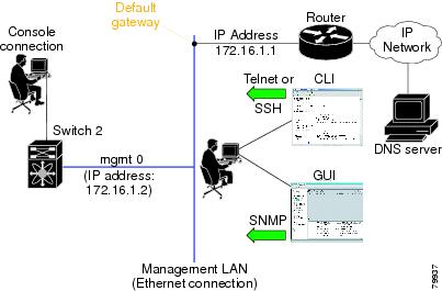
Default Gateway Configuration
The supervisor module sends IP packets with unresolved destination IPv4 addresses to the default gateway (see Figure 12-7).
Figure 12-7 Default Gateway
Telnet Server Connection
The Telnet server is enabled by default on all switches in the Cisco MDS 9000 Family. If you require a secure SSH connection, you need to disable the default Telnet connection and then enable the SSH connection (see the "Generating the SSH Server Key Pair" section on page 39-16).
Note
Tip
Make sure the terminal is connected to the switch and that the switch and terminal are both powered on.
Disabling a Telnet Connection
To disable Telnet connections to the switch using Device Manager, follow these steps:
Step 1
Step 2
Step 3
Telnet is disabled and SSH is enabled on the switch.
Configuring CDP
The Cisco Discovery Protocol (CDP) is an advertisement protocol used by Cisco devices to advertise itself to other Cisco devices in the same network. CDP runs on the data link layer and is independent of Layer 3 protocols. Cisco devices that receive the CDP packets cache the information to make it is accessible through the CLI and SNMP.
CDP is supported on the management Ethernet interface on the supervisor module and the Gigabit Ethernet interfaces on the IPS and MPS-14/2 modules. The CDP daemon is restartable and switchable. The running and startup configurations are available across restarts and switchovers.
CDP version 1 (v1) and version 2 (v2) are supported in Cisco MDS 9000 Family switches. CDP packets with any other version number are silently discarded when received.
When the interface link is established, CDP is enabled by default and three CDP packets are sent at one-second intervals. Following this, the CDP frames are sent at the globally configured refresh interval.
To globally disable CDP using Fabric Manager, follow these steps:
Step 1
Step 2
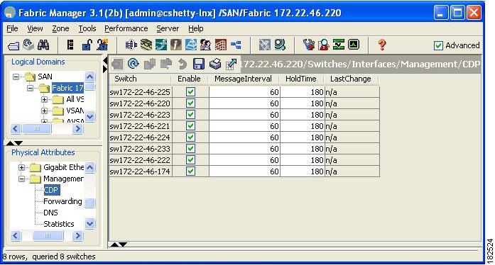
You see the CDP information in the Information pane shown in Figure 12-8.
Figure 12-8 Cisco Discovery Protocol
Step 3
Step 4
To disable CDP using Device Manager, follow these steps:
Step 1
You see the CDP dialog box as shown in Figure 12-8.
Step 2
Step 3
To globally configure the message interval for the CDP protocol using Device Manager, follow these steps:
Step 1
You see the CDP dialog box as shown in Figure 12-8.
Step 2
Step 3
To globally configure the hold time advertised in CDP packets using Device Manager, follow these steps:
Step 1
You see the CDP dialog box as shown in Figure 12-8.
Step 2
Step 3