Installing the GBICs, SFP, SFP+, XFP, CXP, CFP, and CPAK Optics Modules in Cisco ONS 15454 Platforms
This document provides compatibility information and installation procedures for Gigabit Interface Converter (GBIC), Small Form-factor Pluggable (SFP), Enhanced Small-Form-factor Pluggable (SFP+), 10 Gbps Small Form-factor Pluggable (XFP), 120 Gbps 12x Small Form-factor Pluggable (CXP), and C Form-factor Pluggable (CFP) optical modules used with the Cisco ONS 15454 M2, Cisco ONS 15454 M6, ONS 15454, Cisco ONS 15454 SDH, Cisco ONS 15310-CL, Cisco ONS 15310-MA, Cisco ONS 15310-MA SDH, Cisco ONS 15600, and Cisco ONS 15600 SDH nodes. This document also contains removal instructions, cabling, and technical specifications. Use this document in conjunction with platform-specific Cisco user documentation when working with GBICs, SFP, SFP+, XFP, CXP, CFP, or CPAK modules or any other system components.
The GBICs, SFP, SFP+, XFP, CXP, CFP, or CPAK modules are referred to as pluggable port modules (PPMs) in Cisco Transport Controller (CTC).
Changes to This Document
The following table lists new and changed content made to this document since it was first published.
|
Date |
Change Summary |
|---|---|
|
August 2011 |
Updated the specifications for ONS-SC-OSC-ULH SFP in the section "Single-Mode Fiber SFP Port Cabling Specifications". |
|
September 2011 |
Updated the specifications for ONS-SC-OSC-ULH SFP in the section "Single-Mode Fiber SFP Port Cabling Specifications". |
|
November 2011 |
Added a footnote for the following SFPs in the section "Compatibility by Card-Cisco ONS 15454 M2, Cisco ONS 15454 M6, Cisco ONS 15454, and Cisco ONS 15454 SDH":
|
|
February 2012 |
Added a footnote for the ONS-XC-10G-C XFP in the section "Compatibility by Card-Cisco ONS 15454 M2, Cisco ONS 15454 M6, Cisco ONS 15454, and Cisco ONS 15454 SDH". |
|
April 2012 |
Updated the section "DLP-G723 Install PPM on a Line Card". |
|
July 2012 |
|
|
September 2012 |
|
|
March 2013 |
Release 9.6.0.3 updates
|
|
June 2013 |
|
|
July 2013 |
Release 9.8 updates
|
|
November 2013 |
Release 10.0 updates
|
|
March 2015 |
Release 10.3 updates
|
|
June 2015 |
Release 9.7.0.5 updates
|
|
November 2016 |
Release 10.6.1 updates
|
|
April 2017 |
Release 10.6.2 updates
|
|
December 2017 |
Release 10.8 updates.
|
|
March 2019 |
Release 11.0 updates, added specifications for:
|
|
June 2020 |
Release 11.1.1.2 updates. New pluggables added.
|
|
December 2020 |
Release 12.1 updates. New pluggable added.
|
| May 2021 |
Release 12.2 updates. New pluggables added.
|
|
August 2021 |
Release 11.12 updates. New pluggables added.
|
|
June 2023 |
Release 11.13 updates. New pluggable added.
|
Introduction
The GBICs, SFP, SFP+, XFP, CXP, CFP, and CPAK optics modules are hot-swappable I/O devices that plug into a line card port to link the port with the fiber optic network. For all cards, the type of GBICs, SFP, SFP+, XFP, CXP, CFP, and CPAK modules that is plugged into the card is displayed in Cisco Transport Controller (CTC) and in Transaction Language 1 (TL1).
 Note |
|
Compatibility by Card
|
Feature |
Release Information |
Description |
|---|---|---|
|
Pluggables Support |
Cisco ONS 15454 Release 11.12 |
|
|
QSFP-100G-ERL-S Pluggable Support |
Cisco ONS 15454 Release 11.13 |
|
Table 2 through Table 7 lists Cisco ONS 15454 M2, Cisco ONS 15454 M6, ONS 15454, Cisco ONS 15454 SDH, Cisco ONS 15310-CL, Cisco ONS 15310-MA, Cisco ONS 15310-MA SDH, Cisco ONS 15600, and Cisco ONS 15600 SDH cards with their compatible GBIC, SFP, SFP+, and XFP modules.
 Caution |
PPM Compatibility by Card—Cisco ONS 15454 M2 and Cisco ONS 15454 M6
The following table lists Cisco ONS 15454 M2 and Cisco ONS 15454 M6 cards with their compatible PPMs.
|
Card Name |
Compatible SFP (Cisco Product ID) |
Cisco Top Assembly Number (TAN) |
||
|---|---|---|---|---|
|
TNC and TNCE cards |
ONS-SC-OSC-ULH= |
10-2469-01 |
||
|
ONS-SC-OSC-18.0= |
10-2737-01 |
|||
|
ONS-SC-2G-28.7= ONS-SC-2G-30.3=through ONS-SC-2G-60.6= ONS-SC-2G-37.4= ONS-SC-2G-45.3= ONS-SC-2G-53.3= |
10-2307-02 10-2155-02 through 10-2184-02 10-2668-01 10-2670-01 10-2669-01 |
|||
|
ONS-SC-Z3-1470= through ONS-SC-Z3-1610= |
10-2285-01 through 10-2292-01 |
|||
|
ONS-SE-155-1470= through ONS-SE-155-1610= |
10-1996-01 through 10-2003-01 |
|||
|
100G-LC-C cards |
ONS-CXP-100G-SR10= |
10-2790-01 |
||
|
100G-ME-C (100G-CK-C) cards |
ONS-CXP-100G-SR10= |
10-2790-01 |
||
|
CPAK-100G-SR4= |
NA |
|||
|
200G-CK-LC cards |
CPAK-100G-SR4= |
NA |
||
|
CPAK-100G-FR |
800-106219-01 |
|||
|
400G-XP-LC card |
ONS-QC-16GFC-LW |
10-3323-01 |
||
|
QSFP-40G-SR-BD |
10-2945-02 |
|||
|
QSFP-100G-ERL-S |
10-3536-01 |
|||
|
QSFP-40/100-SRBD |
10-3317-01 |
|||
|
QSFP-100G-LR4-S= |
10-3146-01 |
|||
|
QSFP-100G-SR4-S= |
10-3142-01 |
|||
|
QSFP-4x10G-LR-S= |
10-3118-01 |
|||
|
QSFP-100G-FR-S |
10-3248-01 |
|||
|
QSFP-100G-SM-SR |
10-3220-02 |
|||
|
10x10G-LC card |
ONS-SC+-10G-C= |
10-2841-01.
|
||
|
ONS-SC+-10G-ER= |
10-2619-01 |
|||
|
ONS-SC+-10G-LR= |
10-2618-01 |
|||
|
ONS-SC+-10G-SR= |
10-2620-01 |
|||
|
ONS-SC+-10G-ZR= |
10-2730-01 |
|||
|
ONS-CXP-100G-SR10= |
10-2790-01 |
|||
|
ONS-SC+-10G-30.3= through ONS-SC+-10G-61.4= |
10-2690-01 through 10-2729-01 |
|||
|
ONS-SC+-10G-EP30.3= through ONS-SC+-10G-EP61.8= |
10-2797-01 through 10-2836-01 10-2871-01 through 10-2911-01 |
|||
|
SFP-10G-BXU-I |
10-2951-01 |
|||
|
SFP-10G-BXD-I |
10-2952-01
|
|||
|
CFP-LC (ONS 15454 M6 only) |
ONS-CC-100G-LR4= |
10-2736-01 |
||
|
ONS-CC-100GE-LR4= |
10-2795-01 |
|||
|
ONS-CC-40G-LR4= |
10-2744-01 |
|||
|
ONS-CC-40G-FR= |
10-2839-01 |
|||
|
CFP-40G-SR4= |
84-1520-01 |
|||
|
WSE |
ONS-SC+-10G-C= |
10-2841-01 |
||
|
ONS-SC+-10G-EP30.3= through ONS-SC+-10G-EP61.8= |
10-2797-01 through 10-2836-01 10-2871-01 through 10-2911-01 |
|||
|
ONS-SC+-10G-ER= |
10-2619-01 |
|||
|
ONS-SC+-10G-LR= |
10-2618-01 |
|||
|
ONS-SC+-10G-SR= |
10-2620-01 |
|||
|
ONS-SC+-10G-ZR= |
10-2730-01 |
|||
|
ONS-SC+-10G-30.3= through ONS-SC+-10G-61.4= |
10-2690-01 through 10-2729-01 |
|||
|
MR-MXP |
QSFP-40G-SR4= |
10-2672-02 |
||
|
QSFP-40G-LR4= |
10-2842-02 |
|||
|
QSFP-4x10G-LR= |
800-43283-01 |
|||
|
ONS-SC+-10G-LR= |
10-2618-01 |
|||
|
ONS-SC+-10G-SR= |
10-2620-01 |
|||
|
ONS-SC+-10G-C= |
10-2841-01 |
|||
|
QSFP-MLR |
10-3205-01 |
|||
|
ONS-SC+-10G-EP30.3= through ONS-SC+-10G-EP61.8= |
10-2797-01 through 10-2836-01 10-2871-01 through 10-2911-01 |
|||
|
CPAK-100G-SR4= |
800-103176-01 |
|||
|
CPAK-100G-LR4= |
800-39910-09, 800-43011-02 (for CR) |
|||
|
CPAK-100G-SR10= |
10-2924-01 |
|||
|
CPAK-100G-FR |
800-106219-01 |
|||
|
1.2T-MXP |
QSFP-100G-SR4-S |
10-3142-01 |
||
|
QSFP-100G-LR4-S |
10-3146-01 |
|||
|
QSFP-100G-FR-S |
10-3248-01 |
|||
|
QSFP-100G-SM-SR |
10-3220-01 |
|||
|
ONS-CFP2D-400G-C |
10-3500-01 |
|||
|
ONS-QSFP28-LR4 |
10-3204-01 |
|||
|
QDD-400G-LR8-S |
10-3320-01 |
|||
|
QSFP-100G-CWDM4-S |
10-3145-01 |
|||
|
QDD-400G-DR4-S |
10-3441-01 |
|||
|
QDD-400-AOC1M |
||||
|
QDD-400-AOC2M |
10-3430-01 |
|||
|
QDD-400-AOC3M |
10-3431-01 |
|||
|
QDD-400-AOC5M |
||||
|
QDD-400-AOC7M |
||||
|
QDD-400-AOC10M |
||||
|
QDD-400-AOC15M |
||||
|
QDD-400-FR4-S |
10-3321-01 |
PPM Compatibility by Card—Cisco ONS 15454 M2, Cisco ONS 15454 M6, Cisco ONS 15454, and Cisco ONS 15454 SDH
The following table lists Cisco ONS 15454 M2, Cisco ONS 15454 M6, Cisco ONS 15454, and Cisco ONS 15454 SDH cards with their compatible PPMs.
Important notes for the following table:
-
The LED based SFPs—ONS-SI-155-SR-MM, ONS-SE-200-MM, ONS-SI-100-FX, and 15454-SFP-200 do not support the optical power transmitted (OPT) and laser bias current (LBC) optical parameters.
-
The ONS-XC-10G-S1 XFP with TAN 10-2012-02 supports 10G-1200-SM-LL-L, 10GE BASE-LR, 10GE BASE-LW, OC192 SR1, STM64 I-64.1, and OTU-2 at 10.7G. The ONS-XC-10G-S1 XFP with TAN 10-2012-03 supports 10G-1200-SM-LL-L, 10GE BASE-LR, 10GE BASE-LW, OC192 SR1, STM64 I-64.1, and OTU-2 at 10.7G, 11.05G, and 11.09G.
-
The LO-TX-POWER alarm is raised and the traffic is dropped when TX and RX connectors of the ONS-XC-10G-C XFP connected to the trunk port of an OC192-XFP, ADM-10G, OTU2_XP, GE_XP, GE_XPE, 10GE_XP, 10GE_XPE, AR-XP, or AR-MXP card are swapped. Set the trunk port to OOS,DSBLD (ANSI) or Locked,disabled (ETSI) state and then back into the IS (ANSI) or Unlocked (ETSI) state to clear the LO-TXPOWER alarm.
-
Use cables having threaded coaxial connectors with ONS-SC-E3-T3-PW and ONS-SC-EOP3 SFPs to achieve a stable mechanical contact and avoid performance degradation.
-
Y-cable is not supported with CPAK-100G-FR pluggable on 200G-CK-LC card.
|
Card |
Compatible GBIC, SFP, or XFP (Cisco Product ID) |
Cisco Top Assembly Number (TAN) |
|---|---|---|
|
MXP_2.5G_10E card MXP_2.5G_10E_L card MXP_2.5G_10E_C card |
15454-SFP-OC48-IR= |
10-1975-01 |
|
ONS-SE-2G-S1= |
10-2017-01 |
|
|
ONS-SE-2G-L2= |
10-2013-01 |
|
|
ONS-SI-2G-L1= |
10-2102-02 |
|
|
ONS-SI-2G-L2= |
10-1990-02 |
|
|
ONS-SC-2G-28.7= ONS-SC-2G-30.3=through ONS-SC-2G-60.6= ONS-SC-2G-37.4= ONS-SC-2G-45.3= ONS-SC-2G-53.3= |
10-2307-02 10-2155-02 through 10-2184-02 10-2668-01 10-2670-01 10-2669-01 |
|
|
ONS-SC-Z3-1470= through ONS-SC-Z3-1610= |
10-2285-01 through 10-2292-01 |
|
|
MXP_MR_2.5G card MXPP_MR_2.5G card |
15454-SFP-GE+-LX= |
10-1832-03 |
|
15454-SFP-GEFC-SX= |
10-1833-03 |
|
|
ONS-SE-G2F-SX= |
10-2272-02 |
|
|
ONS-SE-G2F-LX= |
10-2273-02 |
|
|
ONS-SE-200-MM= |
10-2248-01 |
|
|
ONS-SE-GE-ZX= |
10-2354-01 |
|
|
ONS-SC-Z3-1470= through ONS-SC-Z3-1610= |
10-2285-01 through 10-2292-01 |
|
|
TXP_MR_10E card TXP_MR_10E_L card TXP_MR_10E_C card |
ONS-XC-10G-SR-MM= |
10-2420-01 |
|
ONS-XC-10G-S1= |
10-2012-02, 10-2012-03 |
|
|
ONS-XC-10G-I2= |
10-2193-02 |
|
|
ONS-XC-10G-L2= (Only when placed in slots 6, 7, 12, or 13) |
10-2194-02 |
|
|
TXP_MR_2.5G card TXPP_MR_2.5G card |
15454-SFP3-1-IR= |
10-1828-01 |
|
15454-SFP12-4-IR= |
10-1976-01 |
|
|
15454-SFP-OC48-IR= |
10-1975-01 |
|
|
15454-SFP-200= |
10-1750-01 |
|
|
15454-SFP-GEFC-SX= |
10-1833-02 |
|
|
15454-SFP-GE+-LX= |
10-1832-03 |
|
|
ONS-SI-155-I1= |
10-1938-02 |
|
|
ONS-SI-622-I1= |
10-1956-02 |
|
|
ONS-SE-G2F-SX= |
10-2272-02 |
|
|
ONS-SE-G2F-LX= |
10-2273-02 |
|
|
ONS-SE-200-MM= |
10-2248-01 |
|
|
ONS-SE-GE-ZX= |
10-2354-01 |
|
|
ONS-SE-2G-S1= |
10-1971-02 |
|
|
ONS-SE-Z1= |
10-2017-01 |
|
|
ONS-SE-2G-L2= |
10-2013-01 |
|
|
ONS-SI-155-SR-MM= |
10-2279-01 |
|
|
ONS-SI-2G-S1= |
10-1992-02 |
|
|
ONS-SI-2G-I1= |
10-1993-02 |
|
|
ONS-SI-2G-L2= |
10-1990-02 |
|
|
ONS-SC-2G-28.7= ONS-SC-2G-30.3=through ONS-SC-2G-60.6= ONS-SC-2G-37.4= ONS-SC-2G-45.3= ONS-SC-2G-53.3= |
10-2307-02 10-2155-02 through 10-2184-02 10-2668-01 10-2670-01 10-2669-01 |
|
|
ONS-SC-Z3-1470= through ONS-SC-Z3-1610= |
10-2285-01 through 10-2292-01 |
|
|
MXP_MR_10DME_C card MXP_MR_10DME_L card |
15454-SFP-GE+-LX= |
10-1832-03 |
|
15454-SFP-GEFC-SX= |
10-1833-02 |
|
|
ONS-SE-4G-MM= |
10-2259-01 |
|
|
ONS-SE-4G-SM= |
10-2252-01 |
|
|
ONS-SE-G2F-LX= |
10-2273-02 |
|
|
ONS-SE-G2F-SX= |
10-2272-02 |
|
|
ONS-SE-ZE-EL= |
10-2351-01 |
|
|
ONS-SI-GE-ZX= |
10-2296-01 |
|
|
40G-MXP-C card 40E-MXP-C card 40ME-MXP-C card |
ONS-XC-8G-SM= |
10-2484-01 |
|
ONS-XC-8G-MM= |
10-2623-01 |
|
|
ONS-XC-10G-S1= |
10-2012-02, 10-2012-03 |
|
|
ONS-XC-10G-I2= |
10-2193-02 |
|
|
ONS-XC-10G-L2= |
10-2194-02 |
|
|
ONS-XC-10G-C= |
10-2480-01 |
|
|
ONS-XC-10G-SR-MM= |
10-2420-01 |
|
|
ONS-XC-10G-1470= through ONS-XC-10G-1610= |
10-2548-01 through 10-2557-01 |
|
|
ONS-XC-10G-EP30.3= through ONS-XC-10G-EP61.4= |
10-2577-01 through 10-2612-01 |
|
|
ADM-10G card |
ONS-SC-155-EL= ONS-SE-Z1= ONS-SE-G2F-LX= ONS-SE-G2F-SX= |
10-2363-01 10-1971-02 10-2273-02 10-2272-02 |
|
ONS-SC-2G-28.7= ONS-SC-2G-30.3=through ONS-SC-2G-60.6= ONS-SC-2G-37.4= ONS-SC-2G-45.3= ONS-SC-2G-53.3= |
10-2307-02 10-2155-02 through 10-2184-02 10-2668-01 10-2670-01 10-2669-01 |
|
|
ONS-SC-Z3-1470= through ONS-SC-Z3-1610= |
10-2285-01 through 10-2292-01 |
|
|
ONS-SI-GE-ZX= |
10-2296-01 |
|
|
ONS-SI-155-L2= |
10-1937-02 |
|
|
ONS-SI-2G-S1= |
10-1992-02 |
|
|
ONS-SI-2G-I1= |
10-1993-02 |
|
|
ONS-SI-622-I1= |
10-1956-02 |
|
|
ONS-SI-2G-L2 |
10-1990-02 |
|
|
ONS-XC-10G-I2= |
10-2193-02 |
|
|
ONS-XC-10G-S1= |
10-2012-02, 10-2012-03 |
|
|
ONS-XC-10G-C= |
10-2480-01 |
|
|
ONS-XC-10G-96C= |
10-2789-01 |
|
|
ONS-XC-10G-SR-MM= |
10-2420-01 |
|
|
ONS-XC-10G-30.3= through ONS-XC-10G-61.4= |
10-2347-02 through 10-2309-02 |
|
|
ONS-XC-10G-1470= through ONS-XC-10G-1610= |
10-2548-01 through 10-2557-01 |
|
|
ONS-XC-10G-EP30.3= through ONS-XC-10G-EP61.4= |
10-2577-01 through 10-2612-01 |
|
|
GE_XP card GE_XPE card |
ONS-SC-2G-28.7= ONS-SC-2G-30.3=through ONS-SC-2G-60.6= ONS-SC-2G-37.4= ONS-SC-2G-45.3= ONS-SC-2G-53.3= |
10-2307-02 10-2155-02 through 10-2184-02 10-2668-01 10-2670-01 10-2669-01 |
|
ONS-SC-Z3-1470= through ONS-SC-Z3-1610= |
10-2285-01 through 10-2292-01 |
|
|
ONS-SC-EOP1= (GE_XPE only) |
30-1446-01 |
|
|
ONS-SC-EOP3= (GE_XPE only) |
30-1449-01 |
|
|
ONS-SC-E1-T1-PW= (GE_XPE only) |
30-1447-01 |
|
|
ONS-SC-E3-T3-PW= (GE_XPE only) |
30-1450-01 |
|
|
ONS-SI-100-LX10= (GE_XPE only) |
10-2294-01 |
|
|
ONS-SI-100-FX= (GE_XPE only) |
10-2350-01 |
|
|
ONS-SI-GE-ZX= |
10-2296-01 |
|
|
ONS-SE-G2F-LX= |
10-2273-02 |
|
|
ONS-SE-G2F-SX= |
10-2272-02 |
|
|
ONS-SE-GE-BXD= |
10-2482-01 |
|
|
ONS-SE-GE-BXU= |
10-2481-01 |
|
|
ONS-SE-ZE-EL= |
10-2351-01 |
|
|
ONS-XC-10G-S1= |
10-2012-02, 10-2012-03 |
|
|
ONS-XC-10G-I2= |
10-2193-02 |
|
|
ONS-XC-10G-C= |
10-2480-01 |
|
|
ONS-XC-10G-96C= |
10-2789-01 |
|
|
ONS-XC-10G-SR-MM= |
10-2420-01 |
|
|
ONS-XC-10G-30.3= through ONS-XC-10G-61.4= |
10-2347-02 through 10-2309-02 |
|
|
ONS-XC-10G-1470= through ONS-XC-10G-1610= |
10-2548-01 through 10-2557-01 |
|
|
ONS-XC-10G-EP30.3= through ONS-XC-10G-EP61.4= |
10-2577-01 through 10-2612-01 |
|
|
10GE_XP card 10GE_XPE card |
ONS-XC-10G-C= |
10-2480-01 |
|
ONS-XC-10G-96C= |
10-2789-01 |
|
|
ONS-XC-10G-S1= |
10-2012-02, 10-2012-03 |
|
|
ONS-XC-10G-I2= |
10-2193-02 |
|
|
ONS-XC-10G-L2= |
10-2194-02 |
|
|
ONS-XC-10G-SR-MM= |
10-2420-01 |
|
|
ONS-XC-10G-30.3= through ONS-XC-10G-61.4= |
10-2347-02 through 10-2309-02 |
|
|
ONS-XC-10G-1470= through ONS-XC-10G-1610= |
10-2548-01 through 10-2557-01 |
|
|
ONS-XC-10G-EP30.3= through ONS-XC-10G-EP61.4= |
10-2577-01 through 10-2612-01 |
|
|
OTU2-XP card |
ONS-XC-10G-C= |
10-2480-01 |
|
ONS-XC-10G-96C= |
10-2789-01 |
|
|
ONS-XC-10G-S1= |
10-2012-02, 10-2012-03 |
|
|
ONS-XC-10G-I2= |
10-2193-02 |
|
|
ONS-XC-10G-L2= |
10-2194-02 |
|
|
ONS-XC-10G-SR-MM= |
10-2420-01 |
|
|
ONS-XC-10G-S1 |
10-2012-03 |
|
|
ONS-XC-10G-30.3= through ONS-XC-10G-61.4= |
10-2347-02 through 10-2309-02 |
|
|
ONS-XC-10G-1470= through ONS-XC-10G-1610= |
10-2548-01 through 10-2557-01 |
|
|
ONS-XC-10G-EP30.3= through ONS-XC-10G-EP61.4= |
10-2577-01 through 10-2612-01 |
|
|
AR-MXP card AR-XP card |
ONS-SC-155-EL= |
10-2363-01 |
|
ONS-SI-155-SR-MM= |
10-2279-01 |
|
|
ONS-SI-155-I1= |
10-1938-02 |
|
|
ONS-SI-155-L2= |
10-1937-02 |
|
|
ONS-SI-622-I1= |
10-1956-02 |
|
|
ONS-SI-2G-S1= |
10-1992-02 |
|
|
ONS-SI-2G-L1= |
10-2102-02 |
|
|
ONS-SI-2G-L2= |
10-1990-02 |
|
|
ONS-SE-Z1= |
10-1971-02 |
|
|
ONS-SE-ZE-EL= |
10-2351-01 |
|
|
ONS-SI-GE-LX= |
10-2300-01 |
|
|
ONS-SI-GE-ZX= |
10-2296-01 |
|
|
ONS-SE-GE-BXU= |
10-2481-01 |
|
|
ONS-SE-GE-BXD= |
10-2482-01 |
|
|
ONS-SI-100-LX10= |
10-2294-01 |
|
|
ONS-SI-100-FX=5 |
10-2350-01 |
|
|
ONS-SE-200-MM= |
10-2248-01 |
|
|
ONS-SE-4G-MM= |
10-2259-01 |
|
|
ONS-SE-4G-SM= |
10-2252-01 |
|
|
ONS-SE-155-1470= through ONS-SE-155-1610= |
10-1996-01 through 10-2003-01 |
|
|
ONS-SC-2G-28.7= ONS-SC-2G-30.3=through ONS-SC-2G-60.6= ONS-SC-2G-37.4= ONS-SC-2G-45.3= ONS-SC-2G-53.3= |
10-2307-02 10-2155-02 through 10-2184-02 10-2668-01 10-2670-01 10-2669-01 |
|
|
ONS-SC-HD3GV-TX= |
10-2630-01 |
|
|
ONS-SC-HD3GV-RX= |
10-2629-01 |
|
|
ONS-XC-10G-S1= |
10-2012-02, 10-2012-03 |
|
|
ONS-XC-10G-I2= |
10-2193-02 |
|
|
ONS-XC-10G-L2= |
10-2194-02 |
|
|
ONS-XC-8G-SM= |
10-2484-01 |
|
|
ONS-XC-8G-MM= |
10-2623-01 |
|
|
ONS-XC-10G-EP30.3= through ONS-XC-10G-EP61.4= |
10-2577-01 through 10-2612-01 |
|
|
ONS-XC-10G-C= |
10-2480-01 |
|
|
ONS-XC-10G-96C= |
10-2789-01 |
|
|
MR-MXP |
CPAK-100G-SR4= |
800-103176-01 |
|
CPAK-100G-FR |
800-106219-01 |
|
|
100G-ME-C (100G-CK-C) cards |
CPAK-100G-SR4= |
800-103176-01 |
|
200G-CK-LC cards |
CPAK-100G-SR4= |
800-103176-01 |
|
CPAK-100G-FR |
800-106219-01 |
PPM Compatibility by Card—Cisco ONS 15454 and Cisco ONS 15454 SDH
The following table lists Cisco ONS 15454 and Cisco ONS 15454 SDH cards with their compatible PPMs.
Important notes for the following table:
-
The G1000-4 cards support coarse wavelength division multiplexing (CWDM) and dense wavelength division multiplexing (DWDM) GBICs. The G1K-4 cards with the Common Language Equipment Identification (CLEI) code of WM5IRWPCAA (manufactured after August 2003) support CWDM and DWDM GBICs. The G1K-4 cards manufactured prior to August 2003 do not support CWDM or DWDM GBICs.
-
The xx.x in 15454-GBIC-xx.x defines the 32 possible wavelengths as shown in the Table 11. For example, a 1530.33 nm DWDM wavelength is represented as 30.3.
-
The xxxx in 15454-GBIC-xxxx defines the 8 possible wavelengths as shown in the Table 10. For example, a 1470 nm CWDM wavelength is represented as 1470.
-
The LED based SFPs—ONS-SE-100-FX, ONS-SI-100-FX, ONS-SI-155-SR-MM, and ONS-SI-622-SR-MM—do not support the optical power transmitted (OPT) and laser bias current (LBC) optical parameters.
-
The ONS-SC-2G-28.7, ONS-SC-2G-33.4, ONS-SC-2G-41.3, ONS-SC-2G-49.3, and ONS-SC-2G-57.3 SFPs are supported in Cisco ONS Software Release 8.5 and later releases.
-
The ONS-SC-2G-37.4, ONS-SC-2G-45.3, and ONS-SC-2G-53.3 SFPs are supported in Cisco ONS Software Release 9.4 and later releases.
-
The ONS-SC-155-EL is supported only on ONS 15454 SDH. The ONS-SC-155-EL is not supported on the MRC-4 card.
-
The OC192SR1/STM64IO Short Reach/10G-SR1/OC192/STM64 Any Reach/10G-XR card is designated as OC192-XFP or STM64 XFP in CTC.
-
The LO-TX-POWER alarm is raised and the traffic is dropped when TX and RX connectors of the ONS-XC-10G-C XFP connected to the trunk port of an OC192-XFP, ADM-10G, OTU2_XP, GE_XP, GE_XPE, 10GE_XP, 10GE_XPE, AR-XP, or AR-MXP card are swapped. Set the trunk port to OOS,DSBLD (ANSI) or Locked,disabled (ETSI) state and then back into the IS (ANSI) or Unlocked (ETSI) state to clear the LO-TXPOWER alarm.
-
The ONS-XC-10G-S1 XFP with TAN 10-2012-02 supports 10G-1200-SM-LL-L, 10GE BASE-LR, 10GE BASE-LW, OC192 SR1, STM64 I-64.1, and OTU-2 at 10.7G. The ONS-XC-10G-S1 XFP with TAN 10-2012-03 supports 10G-1200-SM-LL-L, 10GE BASE-LR, 10GE BASE-LW, OC192 SR1, STM64 I-64.1, and OTU-2 at 10.7G, 11.05G, and 11.09G.
|
Card |
Compatible GBIC, SFP, or XFP (Cisco Product ID) |
Cisco Top Assembly Number (TAN) |
|---|---|---|
|
E1000-2-G card (ONS 15454 SONET only) E1000-2 card |
ONS-GC-GE-SX= |
10-2192-01 |
|
ONS-GC-GE-LX= |
10-2191-01 |
|
|
G1K-4 card G1000-4 card |
15454-GBIC-xx.x= |
10-1845-01 through 10-1876-01 |
|
15454-GBIC-xxxx= |
10-1453-01 through 10-1460-01 |
|
|
ONS-GC-GE-SX= |
10-2192-01 |
|
|
ONS-GC-GE-LX= |
10-2191-01 |
|
|
ONS-GC-GE-ZX= |
10-2190-01 |
|
|
ML1000-2 card |
15454-SFP-LC-SX= |
30-1301-01 |
|
15454-SFP-LC-LX/LH= |
30-1299-01 |
|
|
ONS-SC-GE-LX= |
10-2298-01 |
|
|
ONS-SC-GE-SX= |
10-2301-01 |
|
|
ONS-SI-GE-LX= |
10-2300-01 |
|
|
ONS-SI-GE-SX= |
10-2295-01 |
|
|
ONS-SI-GE-ZX |
10-2296-01 |
|
|
ML100X-8 card CE-100T-8 card (ONS 15454 SDH) |
ONS-SE-100-FX= |
10-2212-01 |
|
ONS-SE-100-LX10= |
10-2213-01 |
|
|
ONS-SI-100-LX10= |
10-2294-01 |
|
|
ONS-SI-100-FX= |
10-2350-01 |
|
|
ONS-SE-100-BX10D= |
10-2352-01 |
|
|
ONS-SE-100-BX10U= |
10-2353-01 |
|
|
CE-1000-4 card |
ONS-GC-GE-SX= |
10-2192-01 |
|
ONS-GC-GE-LX= |
10-2191-01 |
|
|
ONS-GC-GE-ZX= |
10-2190-01 |
|
|
ML-MR-10 card CE-MR-10 card |
ONS-SE-ZE-EL= |
10-2351-01 |
|
ONS-SI-GE-SX= |
10-2295-01 |
|
|
ONS-SI-GE-LX= |
10-2300-01 |
|
|
ONS-SI-GE-ZX= |
10-2296-01 |
|
|
ONS-SI-100-LX10= |
10-2294-01 |
|
|
ONS-SI-100-FX= |
10-2350-01 |
|
|
ONS-SE-100-BX10D= |
10-2352-01 |
|
|
ONS-SE-100-BX10U= |
10-2353-01 |
|
|
ONS-SC-2G-28.7= ONS-SC-2G-30.3=through ONS-SC-2G-60.6= ONS-SC-2G-37.4= ONS-SC-2G-45.3= ONS-SC-2G-53.3= |
10-2307-02 10-2155-02 through 10-2184-02 10-2668-01 10-2670-01 10-2669-01 |
|
|
ONS-SC-Z3-1470= through ONS-SC-Z3-1610= |
10-2285-01 through 10-2292-01 |
|
|
FC_MR-4 card |
ONS-GX-2FC-MMI= |
10-2015-01 |
|
ONS-GX-2FC-SML= |
10-2016-01 |
|
|
MRC-4 card MRC-12 card MRC-12-2.5G card |
ONS-SI-155-I1= |
10-1938-02 |
|
ONS-SI-155-L1= |
10-1957-02 |
|
|
ONS-SI-155-L2= |
10-1937-02 |
|
|
ONS-SI-2G-S1= |
10-1992-02 |
|
|
ONS-SI-2G-I1= |
10-1993-02 |
|
|
ONS-SI-2G-L1= |
10-2102-02 |
|
|
ONS-SI-2G-L2= |
10-1990-02 |
|
|
ONS-SI-622-I1= |
10-1956-02 |
|
|
ONS-SI-622-L1= |
10-1958-02 |
|
|
ONS-SI-622-L2= |
10-1936-02 |
|
|
ONS-SI-155-SR-MM= |
10-2279-01 |
|
|
ONS-SI-622-SR-MM= |
10-2280-01 |
|
|
ONS-SC-155-EL= |
10-2363-01 |
|
|
ONS-SC-Z3-1470= through ONS-SC-Z3-1610= |
10-2285-01 through 10-2292-01 |
|
|
ONS-SC-2G-28.7= ONS-SC-2G-30.3=through ONS-SC-2G-60.6= ONS-SC-2G-37.4= ONS-SC-2G-45.3= ONS-SC-2G-53.3= |
10-2307-02 10-2155-02 through 10-2184-02 10-2668-01 10-2670-01 10-2669-01 |
|
|
ONS-SE-622-1470= through ONS-SE-622-1610= |
10-2004-01 through 10-2011-01 |
|
|
ONS-SE-155-1470= through ONS-SE-155-1610= |
10-1996-01 through 10-2003-01 |
|
|
ONS-SE-Z1= |
10-1971-02 |
|
|
OC192SR1/STM64IO Short Reach/10G-SR1 card |
ONS-XC-10G-S1= |
10-2012-02, 10-2012-03 |
|
OC192/STM64 Any Reach/10G-XR card |
ONS-XC-10G-C= |
10-2480-01 |
|
ONS-XC-10G-S1= |
10-2012-02, 10-2012-03 |
|
|
ONS-XC-10G-I2= |
10-2193-02 |
|
|
ONS-XC-10G-L2= |
10-2194-02 |
|
|
ONS-XC-10G-30.3= through ONS-XC-10G-61.4= |
10-2347-02 through 10-2317-02 |
|
|
ONS-XC-10G-EP30.3= through ONS-XC-10G-EP61.4= |
10-2577-01 through 10-2612-01 |
|
|
MXP_2.5G_10G card |
15454-SFP-OC48-IR= |
10-1975-01 |
|
ONS-SE-2G-S1= |
10-2017-01 |
|
|
MR-MXP |
CPAK-100G-SR4= |
800-103176-01 |
|
200G-CK-LC cards |
CPAK-100G-SR4= |
800-103176-01 |
|
CPAK-100G-FR |
800-106219-01 |
|
|
100G-ME-C (100G-CK-C) cards |
CPAK-100G-SR4= |
800-103176-01 |
PPM Compatibility by Card—Cisco ONS 15310-MA and Cisco ONS 15310-MA SDH
The following table lists Cisco ONS 15310-MA and Cisco ONS 15310-MA SDH cards with their compatible PPMs.
Important notes for the following table:
-
The LED based SFPs—ONS-SI-155-SR-MM and ONS-SI-100-FX—do not support the optical power transmitted (OPT) and laser bias current (LBC) optical parameters.
-
The ONS-SC-155-EL is supported only on ONS 15310-MA SDH.
-
The ONS-SC-2G-28.7, ONS-SC-2G-33.4, ONS-SC-2G-41.3, ONS-SC-2G-49.3, and ONS-SC-2G-57.3 SFPs are supported in Cisco ONS Software Release 8.5 and later releases.
-
The ONS-SC-2G-37.4, ONS-SC-2G-45.3, and ONS-SC-2G-53.3 SFPs are supported in Cisco ONS Software Release 9.4 and later releases.
-
Due to mechanical constraints related to the dimensions of the pluggable device, two ONS-SE-ZE-EL copper SFPs cannot be inserted in the same SFP double cage receptacle. They can only be inserted into slots 1 or 2, 3 or 4, and 5 or 6. Up to three ONS-SE-ZE-EL copper SFPs can be inserted in one CE-MR-6 card.
|
Card |
Compatible GBIC, SFP, or XFP (Cisco Product ID) |
Cisco Top Assembly Number (TAN) |
|---|---|---|
|
CTX2500 card |
ONS-SI-155-I1= |
10-1938-02 |
|
ONS-SI-155-L1= |
10-1957-02 |
|
|
ONS-SI-155-L2= |
10-1937-02 |
|
|
ONS-SI-155-SR-MM= |
10-2279-01 |
|
|
ONS-SC-155-EL= |
10-2363-01 |
|
|
ONS-SI-622-I1= |
10-1956-02 |
|
|
ONS-SI-622-L1= |
10-1958-02 |
|
|
ONS-SI-622-L2= |
10-1936-02 |
|
|
ONS-SI-2G-I1= |
10-1993-02 |
|
|
ONS-SI-2G-L1= |
10-2102-02 |
|
|
ONS-SI-2G-S1= |
10-1992-02 |
|
|
ONS-SI-2G-L2= |
10-1990-02 |
|
|
ONS-SE-Z1= |
10-1971-02 |
|
|
ONS-SE-155-1470= through ONS-SE-155-1610= |
10-1996-01 through 10-2003-01 |
|
|
ONS-SE-622-1470= through ONS-SE-622-1610= |
10-2004-01 through 10-2011-01 |
|
|
ONS-SC-2G-28.7= ONS-SC-2G-30.3=through ONS-SC-2G-60.6= ONS-SC-2G-37.4= ONS-SC-2G-45.3= ONS-SC-2G-53.3= |
10-2307-02 10-2155-02 through 10-2184-02 10-2668-01 10-2670-01 10-2669-01 |
|
|
ONS-SE-2G-1470= through ONS-SE-2G-1610= |
10-2461-01 through 10-2468-01 |
|
|
CE-MR-6 card |
ONS-SE-ZE-EL= |
10-2351-01 |
|
ONS-SI-GE-SX |
10-2295-01 |
|
|
ONS-SI-GE-LX |
10-2300-01 |
|
|
ONS-SI-GE-ZX |
10-2296-01 |
|
|
ONS-SI-100-LX10= |
10-2294-01 |
|
|
ONS-SI-100-FX= |
10-2350-01 |
|
|
ONS-SE-100-BX10D= |
10-2350-01 |
|
|
ONS-SE-100-BX10U= |
10-2353-01 |
PPM Compatibility by Card—Cisco ONS 15310-CL
The following table lists Cisco ONS 15310-CL cards with their compatible PPMs.
|
Card |
Compatible GBIC, SFP, or XFP (Cisco Product ID) |
Cisco Top Assembly Number (TAN) |
|---|---|---|
|
15310-CL-CTX card |
ONS-SI-155-I1= |
10-1938-02 |
|
ONS-SI-155-L1= |
10-1957-02 |
|
|
ONS-SI-155-L2= |
10-1937-02 |
|
|
ONS-SI-622-I1= |
10-1956-02 |
|
|
ONS-SI-622-L1= |
10-1958-02 |
|
|
ONS-SI-622-L2= |
10-1936-02 |
|
|
ONS-SE-155-1470= through ONS-SE-155-1610= |
10-1996-01 through 10-2003-01 |
|
|
ONS-SE-622-1470= through ONS-SE-622-1610= |
10-2004-01 through 10-2011-01 |
PPM Compatibility by Card—Cisco ONS 15600 and Cisco ONS 15600 SDH
The following table lists Cisco ONS 15600 and Cisco ONS 15600 SDH cards with their compatible PPMs.
Important note for the following table:
-
The ONS-XC-10G-S1 XFP with TAN 10-2012-02 supports 10G-1200-SM-LL-L, 10GE BASE-LR, 10GE BASE-LW, OC192 SR1, STM64 I-64.1, and OTU-2 at 10.7G. The ONS-XC-10G-S1 XFP with TAN 10-2012-03 supports 10G-1200-SM-LL-L, 10GE BASE-LR, 10GE BASE-LW, OC192 SR1, STM64 I-64.1, and OTU-2 at 10.7G, 11.05G, and 11.09G.
|
Card |
Compatible GBIC, SFP, or XFP (Cisco Product ID) |
Cisco Top Assembly Number (TAN) |
|---|---|---|
|
ASAP 4PIO card |
ONS-SE-2G-L2= |
10-2013-01 |
|
ONS-SE-Z1= |
10-1971-02 |
|
|
ONS-SI-622-L2= |
10-1936-02 |
|
|
ONS-SI-155-L2= |
10-1937-02 |
|
|
ONS-SI-2G-I1= |
10-1993-02 |
|
|
ONS-SI-2G-L2= |
10-1990-02 |
|
|
ONS-SI-2G-S1= |
10-1992-02 |
|
|
ONS-SC-2G-30.3= through ONS-SC-2G-60.6= |
10-2155-02 through 10-2184-02 |
|
|
ASAP 1PIO card |
ONS-XC-10G-S1= |
10-2012-02, 10-2012-03 |
|
ONS-XC-10G-I2= |
10-2193-02 |
|
|
ONS-XC-10G-L2= |
10-2194-02 |
|
|
ONS-XC-10G-30.3= through ONS-XC-10G-61.4= |
10-2347-02 through 10-2309-02 |
GBIC Description and Specifications
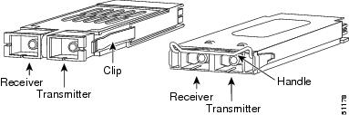
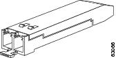
GBICs are integrated fiber-optic transceivers that provide high speed serial links from a port or slot to the network. Various latching mechanisms can be utilized on the GBICs. There is no correlation between the type of latch and the model type (such as SX or LX/LH) or technology type (such as Gigabit Ethernet). See the label on the GBIC for technology type and model. One GBIC model has two clips (one on each side of the GBIC) that secure the GBIC in the slot on the Ethernet card; the other has a locking handle. Both types are shown in GBICs with Clips (Left) and with a Handle (Right).
GBIC dimensions are:
-
Height 0.39 inches (1 cm)
-
Width 1.18 inches (3 cm)
-
Depth 2.56 inches (6.5 cm)
GBIC temperature ranges are:
-
COM—Commercial operating temperature range between 23 degrees Fahrenheit to 158 degrees Fahrenheit (-5 degrees Celsius to 70 degrees Celsius)
-
EXT—Extended operating temperature range between 23 degrees Fahrenheit it to 185 degrees Fahrenheit (-5 degrees Celsius to 85 degrees Celsius)
-
IND—Industrial operating temperature range between -40 degrees Fahrenheit to 185 degrees Fahrenheit (-40 degrees Celsius to 85 degrees Celsius)
Caution |
Do not add labels or markings to the GBICs. |
GBIC Specifications
The following table lists specifications for available GBICs (non-DWDM/CWDM). See the section DWDM and CWDM GBICs for descriptions and specifications for DWDM and CWDM GBICs.
Note |
Operating temperature range for a card with CWDM/DWDM GBICs—15454-GBIC-xx.x and 15454-GBIC-xxxx—installed is limited to -5 to +40 degrees Celsius. Operation with CWDM/DWDM GBICs requires R4.1 or later version of G1K-4 hardware, with CLEI Code WM5IRWPCAA. |
|
GBIC |
Interface |
Transmitter Output Power Min/Max (dBm) |
Receiver Input Power Min/Max (dBm) |
|---|---|---|---|
|
15454-GC-GE-SX= Short Reach |
Gigabit Ethernet Fibre Channel, 1 Gbps |
-9.5 to -4 |
-17 to 0 |
|
15454-GC-GE-LX=Long Reach |
Gigabit Ethernet Fibre Channel, 1 Gbps |
-9.5 to -3 |
-19 to -3 |
|
15454-GC-GE-ZX= Extended Reach |
Gigabit Ethernet |
0 to 5 |
-23 to -3 |
|
15454-GBIC-xx.x= 15454E-GBIC-xx.x= DWDM |
Gigabit Ethernet |
0 to +3 |
-28 to -7 |
|
15454-GBIC-xxxx= 15454E-GBIC-xxxx= CWDM |
Gigabit Ethernet |
1 to 5 |
-29 to -7 |
|
15454-GBIC-LX= / 15454E-GBIC-LX= |
1000Base-LX, SC, SM, or MM |
-9.5 to -3 |
-19 to -3 |
|
15454-GBIC-SX= / 15454E-GBIC-SX= |
1000Base-SX, SC, or MM |
-9.5 to 0 |
-17 to -0 |
|
15454-GBIC-LX/LH= 15454E-GBIC-LX/LH= |
1000Base-LX, SC, SM, or MM |
-9.5 to -3 |
-19 to -3 |
|
15454-GBIC-ZX= 15454E-GBIC-ZX= |
1000Base-ZX, SM |
-5 to 0 |
-23 to -3 |
|
ONS-GX-2FC-MMI= Short Reach |
Fibre Channel, 1 or 2 Gbps |
-9.5 to -5 |
-17 to 0 |
|
ONS-GX-2FC-SML= Long Reach |
Fibre Channel, 1 or 2 Gbps |
-9 to -3 |
-18 to -3 |
Single-Mode Fiber GBIC Port Cabling Specifications
The following table provides cabling specifications for single-mode fiber (SMF) GBICs that you install into Ethernet cards. All GBIC ports have SC-type connectors and the minimum cable distance for all GBICs listed is 6.5 feet (2 m).
Important notes for the following table:
-
The 15454-GC-GE-ZX GBIC operates on SMF optic link spans of up to 49.7 miles (80 km) in length. Link spans of up to 62.1 miles (100 km) are possible using premium SMF or dispersion shifted SMF. When shorter distances of SMF are used, it might be necessary to insert an in-line optical attenuator in the link, to avoid overloading the receiver. For fiber-optic cable spans less than 15.5 miles (25 km), insert a 10 dB in-line optical attenuator between the fiber-optic cable plant and the receiving port on the 15454-GC-GE-ZX GBIC at each end of the link. For fiber-optic cable spans equal to or greater than 15.5 miles (25 km) and less than 31 miles (50 km), insert a 5 dB in-line optical attenuator between the fiber-optic cable plant and the receiving port on the 15454-GC-GE-ZX GBIC at the end of the link.
-
Typical loss on a 1310 nm wavelength SMF is 0.5 dB/km.
-
Typical loss on a 1550 nm wavelength SMF is 0.3 dB/km.
-
The 15454-GC-GE-ZX GBIC requires dispersion-shifted SMF for 100 km (62.1 miles) cable distance.
|
GBIC |
Wavelength |
Fiber Type |
Cable Distance |
|---|---|---|---|
|
15454-GBIC-xx.x= 15454E-GBIC-xx.x= DWDM |
See Table 12 |
9 micron SMF |
100 to 120 km (unamplified) (62 to 74.5 miles) Up to 300 km (amplified) (Up to 186.4 miles) |
|
15454-GBIC-xxxx= 15454E-GBIC-xxxx= CWDM |
See Table 11 |
9 micron SMF |
100 to 120 km (62 to 74.5 miles) |
|
15454-GC-GE-LX= Long Reach |
1310 nm |
9 micron SMF |
10 km (6.2 miles) |
|
50 micron SMF |
550 m (1804 ft) |
||
|
62.5 micron SMF |
275 m (902.2 ft) |
||
|
15454-GC-GE-ZX= Extended Reach |
1550 nm |
9 micron SMF |
70 to 100 km (43.4 to 62 miles) |
|
ONS-GX-2FC-SML= Long Reach |
1310 nm |
9 micron SMF |
10 km (6.2 miles) |
Multimode Fiber GBIC Port Cabling Specifications
Table 9 provides cabling specifications for multimode fiber (MMF) GBICs that you install into Ethernet cards. All GBIC ports have SC-type connectors and the minimum cable distance for all GBICs listed is 6.5 feet (2 m).
Important notes for Table 9:
-
The numbers given for MMF refer to the core diameter. For SMF, 8.3 micron refers to the core diameter. The 9-micron and 10-micron values refer to the mode-field diameter (MFD), which is the diameter of the light-carrying portion of the fiber. This area consists of the fiber core and a small portion of the surrounding cladding. The MFD is a function of the core diameter, the wavelength of the laser, and the refractive index difference between the core and the cladding.
-
When using an LX/LH GBIC with 62.5-micron diameter MMF, you must install a mode-conditioning patchcord (CAB-GELX-625 or equivalent) between the GBIC and the MMF cable on both the transmit and receive ends of the link. The mode-conditioning patchcord is required for link distances less than 328 feet (100 m) or greater than 984 feet (300 m). The mode-conditioning patchcord prevents overdriving the receiver for short lengths of MMF and reduces differential mode delay for long lengths of MMF.
|
GBIC |
Wavelength |
Fiber Type |
Cable Distance |
|---|---|---|---|
|
15454-GC-GE-SX= Short Reach |
850 nm |
62.5 micron MMF |
220 m (722 ft) 275 m (902 ft) |
|
50 micron MMF |
500 m (1640 ft) 550 m (1804 ft) |
||
|
15454-GC-GE-LX= Long Reach |
1310 nm |
62.5 micron MMF |
550 m (1804 ft) |
|
50 micron MMF |
550 m (1804 ft) |
||
|
ONS-GX-2FC-MMI= Short Reach |
850 nm |
62.5 micron MMF |
550 m (1804 ft) |
|
50 micron MMF |
300 m (984.3 ft) |
DWDM and CWDM GBICs
DWDM GBICs (15454-GBIC-xx.x and 15454E-GBIC-xx.x) and CWDM GBICs (15454-GBIC-xxxx and 15454E-GBIC-xxxx) are both WDM technologies that operate over single-mode fibers with SC (subscription channel) connectors. Cisco CWDM GBIC technology uses a 20-nm wavelength grid and Cisco ONS 15454 DWDM GBIC technology uses a 0.8-nm wavelength grid. CTC displays the specific wavelengths of the installed CWDM or DWDM GBICs. DWDM wavelengths are spaced closer together and require more precise lasers than the CWDM. The DWDM spectrum allows for optical signal amplification.
The ONS 15454 SONET/SDH-supported CWDM GBICs reach up to 100 to 120 km over single-mode fiber and can support eight wavelengths as shown in the following table.
|
CWDM GBIC Wavelengths |
1470 nm |
1490 nm |
1510 nm |
1530 nm |
1550 nm |
1570 nm |
1590 nm |
1610 nm |
|
Corresponding GBIC Colors |
Gray |
Violet |
Blue |
Green |
Yellow |
Orange |
Red |
Brown |
|
Band |
47 |
49 |
51 |
53 |
55 |
57 |
59 |
61 |
The ONS 15454 SONET/SDH-supported DWDM GBICs reach up to 100 to 120 km over single-mode fiber and can support 32 different wavelengths at 100-GHz spacing in the C band (see the following table). These wavelengths are compatible with Cisco DWDM filters, such as ONS 15454 MSTP and ONS 15216 FlexLayer. Paired with optical amplifiers, such as the Cisco ONS 15216 EDFA3, the DWDM GBICs allow maximum unregenerated spans of approximately 186.3 miles (300 km).
|
Blue Band |
1530.33 nm |
1531.12 nm |
1531.90 nm |
1532.68 nm |
1534.25 nm |
1535.04 nm |
1535.82 nm |
1536.61 nm |
|
1538.19 nm |
1538.98 nm |
1539.77 nm |
1540.56 nm |
1542.14 nm |
1542.94 nm |
1543.73 nm |
1544.53 nm |
|
|
Red Band |
1546.12 nm |
1546.92 nm |
1547.72 nm |
1548.51 nm |
1550.12 nm |
1550.92 nm |
1551.72 nm |
1552.52 nm |
|
1554.13 nm |
1554.94 nm |
1555.75 nm |
1556.55 nm |
1558.17 nm |
1558.98 nm |
1559.79 nm |
1560.61 nm |
Placement of CWDM or DWDM GBICs
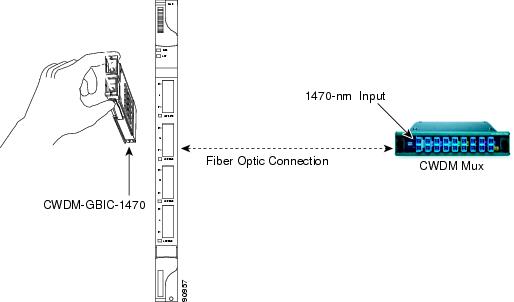
CWDM or DWDM GBICs come in set wavelengths and are not provisionable. The wavelengths are printed on each GBIC, for example, CWDM-GBIC-1490. The user must insert the specific GBIC transmitting the wavelength required to match the input of the CWDM/DWDM device for successful operation (as shown in the following figure). Follow your site plan or network diagram for the required wavelengths.
The DLP-G723 Install PPM on a Line Card task contains specific procedure for installing GBICs and DLP-G724 Connecting Single-Mode and Multimode Optical Fiber task contains specific procedure for attaching optical fiber to GBICs.
Example of CWDM or DWDM GBIC Application
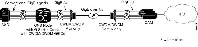
A G-Series card equipped with CWDM or DWDM GBICs supports the delivery of unprotected Gigabit Ethernet service in Metro DWDM applications (as shown in the following figure). It can be used in short-haul and long-haul applications.
SFP and SFP+ Description and Specifications
The SFP modules are integrated fiber optic transceivers that provide high speed serial links from a port or slot to the network. The SFP+ transceiver is an enhancement over the SFP optics developed for 1 Gbps Ethernet and 1 Gbps, 2 Gbps, and 4 Gbps Fibre Channel. The SFP+ modules extend the data rate up to 11.10 Gbps. SFP+ modules also provide 2-wire serial, I2C interface. The I2C interface is used for serial ID, digital diagnostics, and module control functions.
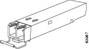
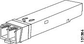
Various latching mechanisms can be utilized on the SFP and SFP+ modules. There is no correlation between the type of latch and the model type (such as SX or LX/LH) or technology type (such as Gigabit Ethernet). See the label on the SFP and SFP+ modules for technology type and model. One type of latch available is a mylar tab as shown in Figure 4, a second type of latch is an actuator/button (Figure 5), and the third type of latch is a bail clasp (Figure 6 and Figure 7).
SFP and SFP+ module dimensions are:
-
Height 0.33 inches (8.5 mm)
-
Width 0.53 inches (13.4 mm)
-
Depth 2.22 inches (56.5 mm)
SFP and SFP+ module temperature ranges are:
-
COM—Commercial operating temperature range between 23 degrees Fahrenheit to 158 degrees Fahrenheit (–5 degrees Celsius to 70 degrees Celsius)
-
EXT—Extended operating temperature range between 23 degrees Fahrenheit it to 185 degrees Fahrenheit (–5 degrees Celsius to 85 degrees Celsius)
-
IND—Industrial operating temperature range between –40 degrees Fahrenheit to 185 degrees Fahrenheit (–40 degrees Celsius to 85 degrees Celsius)
Caution |
Do not add labels or markings to the SFP and SFP+ modules. |
Note |
From Release 11.0, ONS-SI-100-LX-10= and ONS-SE-100-LX-10= pluggables are supported on NCS 2015-ECU for MSM. |
SFP Specifications
The following table lists specifications for available SFPs.
Important notes for the following table:
-
The ONS-SC-2G-28.7, ONS-SC-2G-33.4, ONS-SC-2G-41.3, ONS-SC-2G-49.3, and ONS-SC-2G-57.3 SFPs are supported in Cisco ONS Software Release 8.5 and later releases.
-
The ONS-SC-2G-28.7= through ONS-SC-2G-60.6= SFPs on the TNC and TNCE cards support only GE payload.
-
The LED based SFPs ( ONS-SI-100-FX) do not support the optical power transmitted (OPT) and laser bias current (LBC) optical parameters.
-
For ONS-SE-4G-SM SFP, specified Optical Modulation Amplitude (OMA) at 4.25 Gbps is equal to an average power of -7.3 dBm at an ER of 9 dB (transmitter output power) and specified OMA at 4.25 Gbps is equal to an average power of -17.3 dBm at an ER of 9 dB (receiver power input).
-
For ONS-SE-2G-30.3 through ONS-SE-2G-60.6 SFPs, the power limited performance at bit error rate (BER) = 10e-12 with SONET framed PRBS23, optical signal-to-noise ratio (OSNR) of 21 dB, 0.1 nm bandwidth (BW) and power limited performance at BER = 10e-12 with SONET framed PRBS23, OSNR of 16 dB, 0.1 nm BW.
|
SFP |
Interface |
Transmitter Output Power Min/Max (dBm) |
Receiver Input Power Min/Max (dBm) |
|---|---|---|---|
|
ONS-SC-2G-28.7= through ONS-SC-2G-60.6= |
OC-48, STM-16, GE |
0 to +4 |
–28 to –9 |
|
ONS-SC-4G-30.3= through ONS-SC-4G-61.4= |
4G FC |
0 to +4 |
–28 to –9 |
|
ONS-SE-100-FX= |
100 Mbps long reach - 1310 nm - SM - LC, EXT-TEMP |
–20 to –14 |
–31 to –14 |
|
ONS-SE-100-LX10= |
100 Mbps long reach - 1310 nm - MM - LC, EXT-TEMP |
–15 to –8 |
–28 to –8 |
|
ONS-SE-155-1470= through ONS-SE-155-1610= |
OC-3, STM-1 |
0 to +5 |
–34 to –7 |
|
ONS-SE-4G-MM= |
4G FC/Ficon |
–9 to –2.5 |
–15 –18 to –3 |
|
ONS-SE-4G-SM= |
4G FC/Ficon |
290 microwatts OMA |
29 microwatts OMA |
|
ONS-SE-622-1470= through ONS-SE-622-1610= |
OC-12, STM-4 |
0 to +5 |
–28 to –7 |
|
ONS-SE-2G-30.3= through ONS-SE-2G-60.6= |
OC-48, STM-16 |
0 to +4 |
–28 to –9 |
|
ONS-SE-2G-L2= |
OC-48, STM-16 |
–2.0 to 3.0 |
–22 to –9 |
|
ONS-SE-2G-S1= |
OC-48, STM-16 |
–10 to –3 |
–28 to –9 |
|
ONS-SE-Z1= |
OC-3, OC-12, OC48, STM-1, STM-4, STM-16 |
–5.0 to 0 |
–23 to –3 (155.52/ 622.08 Mbps) –19 to –3 (1250 Mbps) –18 to 0 (2488.32 Mbps) |
|
ONS-SI-155-I1= |
OC-3, STM-1 |
–15 to –8.0 |
–28 to –8 |
|
ONS-SI-155-L1= |
OC-3, STM-1 |
–5.0 to 0 |
–34 to –10 |
|
ONS-SI-155-L2= |
OC-3, STM-1 |
–5.0 to 0 |
–34 to –10 |
|
ONS-SI-2G-I1= |
OC-48, STM-16 |
–5.0 to 0 |
–18 to –0 |
|
ONS-SI-2G-L1= |
OC-48, STM-16 |
–2 to +3 |
–27 to –9 |
|
ONS-SI-2G-L2= |
OC-48, STM-16 |
–2 to +3 |
–28 to –9 |
|
ONS-SI-2G-S1= |
OC-48, STM-16 |
–10 to –3 |
–18 to –3 |
|
ONS-SI-622-I1= |
OC-12, OC-3, STM-4, STM-1 |
–15 to –8.0 |
–28 to –8 |
|
ONS-SI-622-L1= |
OC-12, STM-4 |
–3.0 to 2.0 |
–28 to –8 |
|
ONS-SI-622-L2= |
OC-12, STM-4 |
–3.0 to 2.0 |
–28 to –8 |
|
15454-SFP-LC-SX=/ ONS-SC-GE-SX= |
Gigabit Ethernet (GE) |
–9.5 to –4 |
–17 to 0 |
|
15454-SFP-LC-LX=/ ONS-SC-GE-LX= |
GE |
–9.5 to –3 |
–19 to –3 |
|
15454-SFP3-1-IR= |
OC-3 |
–15 to –8 |
–28 to –8 |
|
15454E-SFP-L.1.1= |
STM-1 |
–15 to –8 |
–34 to –10 |
|
15454-SFP12-4-IR= |
OC-12, D1 Video |
–15 to –8 |
–28 to –7 |
|
15454E-SFP-L.4.1= |
STM-4, D1 Video |
–15 to –8 |
–28 to –8 |
|
15454-SFP-OC48-IR= |
OC-48, DV6000 (C-Cor) |
–5 to +0 |
–18 to +0 |
|
15454E-SFP-L.16.1= |
STM-16, DV6000 (C-Cor) |
–5 to +0 |
–18 to +0 |
|
15454-SFP-200=/ 15454E-SFP-200= |
Enterprise System Connection (ESCON) |
–20.5 to -15 |
–29 to –14 |
|
15454-SFP-GEFC-SX=/ 15454E-SFP-GEFC-S=/ ONS-SE-G2F-SX= |
Fibre Channel (1 and 2 Gbps), FICON, GE |
–10 to –3.5 |
–17 to 0 for 1FC, GE –15 for 2FC |
|
15454-SFP-GE+-LX=/ 15454E-SFP-GE+-LX=/ ONS-SE-G2F-LX |
Fibre Channel (1 and 2 Gbps), FICON, GE, High-definition television (HDTV) |
–9.5 to –3.0 |
–20 to –3 for 1FC, 2FC, and GE |
|
ONS-SI-155-SR-MM= |
OC-3, STM-1 |
–19 to –14 |
–14 to –5 |
|
ONS-SI-622-SR-MM= |
OC-12, STM-4 |
–19 to –14 |
–14 to –5 |
|
ONS-SC-Z3-1470= through ONS-SC-Z3-1610= |
OC48/STM16/GE |
0 to +5 |
–9 (min) |
|
ONS-SE-2G-1470= through ONS-SE-2G-1610= |
OC48/STM16/GE |
–1 to +4 |
–28 to –9 |
|
ONS-SE-Z1= |
OC-3/STM-1 OC-12/STM-4 OC-48/STM-16 Fibre Channel (1 and 2 Gbps) GE |
–5 to 0 |
–23 to –3 (OC-3) –23 to –3 (OC-12) –18 to 0 (OC-48) 0 to –21 (Fibre Channel) 0 to –22 (GE) |
|
ONS-SI-2G-S1 |
OC-48/STM-16 |
–10 to –3 |
–3 (min) |
|
ONS-SE-155-1470 through ONS-SE-155-1610 |
OC-3/STM-1 |
0 to 5 |
–7 to 0 |
|
ONS-SI-GE-ZX |
GE |
0 to +5 |
–23 to –3 |
|
ONS-SE-GE-ZX |
GE |
0 to +5 |
–23 to –3 |
|
ONS-SE-ZE-EL |
1000 Base-T Ethernet |
— |
— |
|
ONS-SE-GE-BXD= |
1000Base BXD/GE |
–9 to –3 |
–19.5 to –3 |
|
ONS-SE-GE-BXU= |
1000Base BXU/GE |
–9 to –3 |
–19.5 to –3 |
|
ONS-SC-EOP1= |
Fast Ethernet over DS1/E1 |
— |
— |
|
ONS-SC-EOP3= |
Fast Ethernet over DS3/E3 |
— |
— |
|
ONS-SC-E1-T1-PW= |
E1/DS1 over Fast Ethernet |
— |
— |
|
ONS-SC-E3-T3-PW- |
E3/DS3 PDH over Fast Ethernet |
— |
— |
|
ONS-SI-100-FX= |
Fast Ethernet |
–19.0 to –14 |
–31.0 to –14 |
|
ONS-SI-100-LX10= |
Fast Ethernet |
–15.0 to –8 |
–28 to –8 |
|
ONS-SC-OSC-ULH= |
OC3/STM1/FE OSC |
+1 to +5 |
43 to –7 |
|
ONS-SC-OSC-18.0= |
OC3/STM1/FE OSC for RAMAN 1518.0 nm signal |
+2.5 to +7 |
43 to –7 |
|
ONS-SE-155-1510= |
OC3/FE TNC OSC |
+1 to +5 |
43 to –7 |
|
ONS-SC-Z3-1510 |
GE TNC OSC |
0 to +5 |
–29 to –9 |
|
ONS-SC-HD3GV-TX= |
3G HD Video TX |
–3 to 0 |
–20 |
|
ONS-SC-HD3GV-RX= |
3G HD Video RX |
–3 to 0 |
–20 |
SFP+ Specifications
The following table lists specifications for available SFP+ modules.
|
SFP+ |
Interface |
Transmitter Output Power Min/Max (dBm) |
Receiver Input Power Min/Max (dBm) |
|---|---|---|---|
|
ONS-SC+-10G-ER= |
10GBASE-ER |
–4.7 to +4.0 |
–15.8 to –1.0 |
|
ONS-SC+-10G-LR= |
10GBASE-LR |
–8.2 to +0.5 |
–14.1 to +0.5 |
|
ONS-SC+-10G-SR= |
10GBASE-SR |
–7.3 to –1.2 |
–9.9 to –1.0 |
|
ONS-SC+-10G-ZR= |
10GBASE-ZR |
–7.3 to –1.3 |
–11 to –1 |
|
ONS-SC+-10G-C= |
OC-192, STM-64, 8GFC, 10GE, 10GFC, OTU2 |
–1.0 to +3.0 |
|
|
ONS-SC+-10G-30.3= through ONS-SC+-10G-61.4= |
OC-192, STM-64, 8GFC, 10GE, 10GFC, OTU2, OTU2e |
–1.0 to +3.0 |
|
|
ONS-SC+-10G-EP30.3= through ONS-SC+-10G-EP61.8= |
OC-192, STM-64, 8GFC, 10GE, 10GFC, OTU2, OTU2e |
–2.0 to +2.0 |
|
SFP and SFP+ Port Cabling Specifications
Table 15 provides cabling specifications for the SMF SFPs, Table 16 provides cabling specifications for MMF SFPs, Table 17 provides cabling specifications of video SFPs, Table 18 provides cabling specifications for SMF SFP+ modules, and Table 19 provides cabling specifications for MMF SFP+ modules that you install into interface cards. The ports of the listed SFP and SFP+ modules have LC-type connectors.
Single-Mode Fiber SFP Port Cabling Specifications
The following table provides cabling specifications for the SMF SFPs.
Important notes for the following table:
-
Typical loss on a 1310 nm wavelength SMF is 0.6 dB/km.
-
The ONS-SC-2G-28.7, ONS-SC-2G-33.4, ONS-SC-2G-41.3, ONS-SC-2G-49.3, and ONS-SC-2G-57.3 SFPs are supported in Cisco ONS Software Release 8.5 and later releases.
-
The ONS-SC-2G-xx.x cable distance varies depending on the DWDM system installation.
-
The ONS-SC-2G-37.4, ONS-SC-2G-45.3, and ONS-SC-2G-53.3 SFPs are supported in Cisco ONS Software Release 9.4 and later releases.
|
SFP |
Transmit Wavelength |
Fiber Type |
Cable Distance |
|---|---|---|---|
|
ONS-SC-2G-28.7= |
1528.70 nm |
9 micron SMF |
N/A |
|
ONS-SC-2G-30.3= |
1530.33 nm |
9 micron SMF |
N/A |
|
ONS-SC-2G-31.1= |
1531.12 nm |
9 micron SMF |
N/A |
|
ONS-SC-2G-31.9= |
1531.90 nm |
9 micron SMF |
N/A |
|
ONS-SC-2G-32.6= |
1532.68 nm |
9 micron SMF |
N/A |
|
ONS-SC-2G-33.4= |
1533.47 nm |
9 micron SMF |
N/A |
|
ONS-SC-2G-34.2= |
1534.25 nm |
9 micron SMF |
N/A |
|
ONS-SC-2G-35.0= |
1535.04 nm |
9 micron SMF |
N/A |
|
ONS-SC-2G-35.8= |
1535.82 nm |
9 micron SMF |
N/A |
|
ONS-SC-2G-36.6= |
1536.61 nm |
9 micron SMF |
N/A |
|
ONS-SC-2G-37.4= |
1537.40 nm |
9 micron SMF |
N/A |
|
ONS-SC-2G-38.1= |
1538.19 nm |
9 micron SMF |
N/A |
|
ONS-SC-2G-38.9= |
1538.98 nm |
9 micron SMF |
N/A |
|
ONS-SC-2G-39.7= |
1539.77 nm |
9 micron SMF |
N/A |
|
ONS-SC-2G-40.5= |
1540.56 nm |
9 micron SMF |
N/A |
|
ONS-SC-2G-41.3= |
1541.35 nm |
9 micron SMF |
N/A |
|
ONS-SC-2G-42.1= |
1542.14 nm |
9 micron SMF |
N/A |
|
ONS-SC-2G-42.9= |
1542.94 nm |
9 micron SMF |
N/A |
|
ONS-SC-2G-43.7= |
1543.73 nm |
9 micron SMF |
N/A |
|
ONS-SC-2G-44.5= |
1544.53 nm |
9 micron SMF |
N/A |
|
ONS-SC-2G-45.3= |
1545.32 nm |
9 micron SMF |
N/A |
|
ONS-SC-2G-46.1= |
1546.12 nm |
9 micron SMF |
N/A |
|
ONS-SC-2G-46.9= |
1546.92 nm |
9 micron SMF |
N/A |
|
ONS-SC-2G-47.7= |
1547.72 nm |
9 micron SMF |
N/A |
|
ONS-SC-2G-48.5= |
1548.51 nm |
9 micron SMF |
N/A |
|
ONS-SC-2G-49.3= |
1549.32 nm |
9 micron SMF |
N/A |
|
ONS-SC-2G-50.1= |
1550.12 nm |
9 micron SMF |
N/A |
|
ONS-SC-2G-50.9= |
1550.92 nm |
9 micron SMF |
N/A |
|
ONS-SC-2G-51.7= |
1551.72 nm |
9 micron SMF |
N/A |
|
ONS-SC-2G-52.5= |
1552.52 nm |
9 micron SMF |
N/A |
|
ONS-SC-2G-53.3= |
1553.33 nm |
9 micron SMF |
N/A |
|
ONS-SC-2G-54.1= |
1554.13 nm |
9 micron SMF |
N/A |
|
ONS-SC-2G-54.9= |
1554.94 nm |
9 micron SMF |
N/A |
|
ONS-SC-2G-55.7= |
1555.75 nm |
9 micron SMF |
N/A |
|
ONS-SC-2G-56.5= |
1556.55 nm |
9 micron SMF |
N/A |
|
ONS-SC-2G-57.3= |
1557.36 nm |
9 micron SMF |
N/A |
|
ONS-SC-2G-58.1= |
1558.17 nm |
9 micron SMF |
N/A |
|
ONS-SC-2G-58.9= |
1558.98 nm |
9 micron SMF |
N/A |
|
ONS-SC-2G-59.7= |
1559.79 nm |
9 micron SMF |
N/A |
|
ONS-SC-2G-60.6= |
1560.61 nm |
9 micron SMF |
N/A |
|
ONS-SE-155-1470= |
1470 nm |
9 micron SMF |
120 km (74.56 miles) |
|
ONS-SE-155-1490= |
1490 nm |
9 micron SMF |
120 km (74.56 miles) |
|
ONS-SE-155-1510= |
1510 nm |
9 micron SMF |
120 km (74.56 miles) |
|
ONS-SE-155-1530= |
1530 nm |
9 micron SMF |
120 km (74.56 miles) |
|
ONS-SE-155-1550= |
1550 nm |
9 micron SMF |
120 km (74.56 miles) |
|
ONS-SE-155-1570= |
1570 nm |
9 micron SMF |
120 km (74.56 miles) |
|
ONS-SE-155-1590= |
1590 nm |
9 micron SMF |
120 km (74.56 miles) |
|
ONS-SE-155-1610= |
1610 nm |
9 micron SMF |
120 km (74.56 miles) |
|
ONS-SE-622-1470= |
1470 nm |
9 micron SMF |
100 km (62.14 miles) |
|
ONS-SE-622-1490= |
1490 nm |
9 micron SMF |
100 km (62.14 miles) |
|
ONS-SE-622-1510= |
1510 nm |
9 micron SMF |
100 km (62.14 miles) |
|
ONS-SE-622-1530= |
1530 nm |
9 micron SMF |
100 km (62.14 miles) |
|
ONS-SE-622-1550= |
1550 nm |
9 micron SMF |
100 km (62.14 miles) |
|
ONS-SE-622-1570= |
1570 nm |
9 micron SMF |
100 km (62.14 miles) |
|
ONS-SE-622-1590= |
1590 nm |
9 micron SMF |
100 km (62.14 miles) |
|
ONS-SE-622-1610= |
1610 nm |
9 micron SMF |
100 km (62.14 miles) |
|
ONS-SE-2G-L2= |
1550 nm |
9 micron SMF |
80 km (49.71 miles) |
|
ONS-SE-2G-S1= Short Reach |
1310 nm |
9 micron SMF |
2 km (1.2 miles) |
|
ONS-SE-4G-SM= |
1270 – 1355 nm |
9 micron SMF |
10 km (6.2 miles) |
|
ONS-SE-Z1= |
1310 nm |
9 micron SMF |
15 km (9.3 miles) |
|
ONS-SI-155-I1= Intermediate Reach |
1310 nm |
9 micron SMF |
21 km (13.05 miles) |
|
ONS-SI-155-L1= Long Reach |
1310 nm |
9 micron SMF |
50 km (31.07 miles) |
|
ONS-SI-155-L2= Long Reach |
1550 nm |
9 micron SMF |
100 km (62.14 miles) |
|
ONS-SI-2G-I1= |
1310 nm |
9 micron SMF |
15 km (9.3 miles) |
|
ONS-SI-2G-L1= |
1310 nm |
9 micron SMF |
40 km (25.80 miles) |
|
ONS-SI-2G-L2= |
1550 nm |
9 micron SMF |
80 km (49.71 miles) |
|
ONS-SI-2G-S1= |
1310 nm |
9 micron SMF |
2 km (1.2 miles) |
|
ONS-SI-622-I1= Intermediate Reach |
1310 nm |
9 micron SMF |
21 km (13.05 miles) |
|
ONS-SI-622-L1= Long Reach |
1310 nm |
9 micron SMF |
42 km (26.10 miles) |
|
ONS-SI-622-L2= Long Reach |
1550 nm |
9 micron SMF |
85 km (52.82 miles) |
|
15454-SFP-LC-LX=/ 15454E-SFP-LC-LX=/ ONS-SC-GE-LX Long Reach |
1310 nm |
9 micron SMF |
10 km (6.2 miles) |
|
15454-SFP3-1-IR= Intermediate Reach |
1310 nm |
9 micron SMF |
15 km (9.3 miles) |
|
15454E-SFP-L.1.1= Short Haul |
1310 nm |
9 micron SMF |
15 km (9.3 miles) |
|
15454-SFP12-4-IR= Intermediate Reach |
1310 nm |
9 micron SMF |
15 km (9.3 miles) |
|
15600-SFP-12-4-LR2= |
1530 nm |
9 micron SMF |
80 km (49.71 miles) |
|
15454E-SFP-L.4.1= Short Haul |
1310 nm |
9 micron SMF |
15 km (9.3 miles) |
|
15454-SFP-OC48-IR= Intermediate Reach |
1310 nm |
9 micron SMF |
15 km (9.3 miles) |
|
15454E-SFP-L.16.1= Short Haul |
1310 nm |
9 micron SMF |
15 km (9.3 miles) |
|
15454-SFP-GE+-LX=/ 15454E-SFP-GE+-LX= Long Reach |
1310 nm |
9 micron SMF |
10 km (6.2 miles) for FC 1G, FC 2G, and GE 5 km (3.1 miles) for HDTV |
|
ONS-SC-Z3-1470= Long Reach |
1470 nm |
9 micron SMF |
80 km (49.71 miles) |
|
ONS-SC-Z3-1490= Long Reach |
1490 nm |
9 micron SMF |
80 km (49.71 miles) |
|
ONS-SC-Z3-1510= Long Reach |
1510 nm |
9 micron SMF |
80 km (49.71 miles) |
|
ONS-SC-Z3-1530= Long Reach |
1530 nm |
9 micron SMF |
80 km (49.71 miles) |
|
ONS-SC-Z3-1550= Long Reach |
1550 nm |
9 micron SMF |
80 km (49.71 miles) |
|
ONS-SC-Z3-1570= Long Reach |
1570 nm |
9 micron SMF |
80 km (49.71 miles) |
|
ONS-SC-Z3-1590= Long Reach |
1590 nm |
9 micron SMF |
80 km (49.71 miles) |
|
ONS-SC-Z3-1610= Long Reach |
1610 nm |
9 micron SMF |
80 km (49.71 miles) |
|
ONS-SE-Z1= Intermediate Reach |
1310 nm |
9 micron SMF |
30 km (18.6 miles) for OC-3/STM1, OC-12/STM-4, OC-48/STM-16, and Fibre Channel (1 and 2 Gbps) 20 km (12.4 miles) for GE |
|
ONS-SI-2G-S1= Short Reach |
1310 nm |
9 micron SMF |
2 km (1.2 miles) |
|
ONS-SE-155-1470= Long Reach |
1470 nm |
9 micron SMF |
80 km (49.71 miles) |
|
ONS-SE-155-1490= Long Reach |
1490 nm |
9 micron SMF |
80 km (49.71 miles) |
|
ONS-SE-155-1510= Long Reach |
1510 nm |
9 micron SMF |
80 km (49.71 miles) |
|
ONS-SE-155-1530= Long Reach |
1530 nm |
9 micron SMF |
80 km (49.71 miles) |
|
ONS-SE-155-1550= Long Reach |
1550 nm |
9 micron SMF |
80 km (49.71 miles) |
|
ONS-SE-155-1570= Long Reach |
1570 nm |
9 micron SMF |
80 km (49.71 miles) |
|
ONS-SE-155-1590= Long Reach |
1590 nm |
9 micron SMF |
80 km (49.71 miles) |
|
ONS-SE-155-1610= Long Reach |
1610 nm |
9 micron SMF |
80 km (49.71 miles) |
|
ONS-SE-622-1470= Long Reach |
1470 nm |
9 micron SMF |
100 km (62.14 miles) |
|
ONS-SE-622-1490= Long Reach |
1490 nm |
9 micron SMF |
100 km (62.14 miles) |
|
ONS-SE-622-1510= Long Reach |
1510 nm |
9 micron SMF |
100 km (62.14 miles) |
|
ONS-SE-622-1530= Long Reach |
1530 nm |
9 micron SMF |
100 km (62.14 miles) |
|
ONS-SE-622-1550= Long Reach |
1550 nm |
9 micron SMF |
100 km (62.14 miles) |
|
ONS-SE-622-1570= Long Reach |
1570 nm |
9 micron SMF |
100 km (62.14 miles) |
|
ONS-SE-622-1590= Long Reach |
1590 nm |
9 micron SMF |
100 km (62.14 miles) |
|
ONS-SE-622-1610= Long Reach |
1610 nm |
9 micron SMF |
100 km (62.14 miles) |
|
ONS-SI-GE-ZX= |
1550 nm |
9 micron SMF |
80 km (49.71 miles) |
|
ONS-SE-GE-ZX= |
1550 nm |
9 micron SMF |
80 km (49.71 miles) |
|
ONS-SE-GE-BXD= |
1550 nm |
9 micron SMF |
80 km (49.71 miles) |
|
ONS-SE-GE-BXU= |
1550 nm |
9 micron SMF |
80 km (49.71 miles) |
|
ONS-SC-EOP1= |
— |
9 micron SMF |
2.5 km (1.56 miles) |
|
ONS-SC-EOP3= |
— |
9 micron SMF |
2.5 km (1.56 miles) |
|
ONS-SC-E1-T1-PW= |
— |
9 micron SMF |
1.83 km (1.136 miles) |
|
ONS-SC-E3-T3-PW= |
— |
9 micron SMF |
1.83 km (1.136 miles) |
|
ONS-SC-E1-T1-CES= |
— |
9 micron SMF |
1.83 km (1.136 miles) |
|
ONS-SC-E3-T3-CES= |
— |
9 micron SMF |
1.83 km (1.136 miles) |
|
ONS-SI-100-LX10= |
1310 nm |
9 micron SMF |
2 km (1.24 miles) |
|
ONS-SC-OSC-ULH= |
1500 – 1520 nm |
9 micron SMF |
160 km (99.41 miles) |
|
ONS-SC-OSC-18.0= |
1518 nm |
— |
— |
Multimode Fiber SFP Port Cabling Specifications
The following table provides cabling specifications for the MMF SFPs.
|
SFP |
Transmit Wavelength |
Fiber Type |
Cable Distance |
|---|---|---|---|
|
ONS-SE-4G-MM= |
830 – 860 nm |
62.5 micron MMF |
300 m (984 ft) |
|
50.0 micron MMF |
500 m (1640 ft) |
||
|
ONS-SE-100-FX= |
1270 – 1380 nm |
MMF |
2 km (1.24 miles) |
|
ONS-SE-100-LX10= |
1260 – 1360 nm |
MMF |
15 km (9.32 miles) |
|
15454-SFP-LC-SX= Short Reach |
850 nm |
62.5 micron MMF |
220 m (722 ft) 275 m (902 ft) |
|
50.0 micron MMF |
500 m (1640 ft) 550 m (1804 ft) |
||
|
15454-SFP-LC-LX= Long Reach |
1310 nm |
62.5 micron MMF |
550 m (1804 ft) |
|
50.0 micron MMF |
550 m (1804 ft) |
||
|
15454-SFP-200= Long Reach |
1310 nm |
62.5 micron MMF |
2 km (1.2 miles) |
|
ONS-SE-200-MM= |
1310 nm |
62.5 micron MMF |
2 km (1.2 miles) |
|
15454-SFP-GEFC-SX= Short Reach |
850 nm |
62.5 micron MMF |
300 m (984 ft) for FC 1 Gbps and GE 150 m (492 ft) for FC 2 Gbps |
|
50.0 micron MMF |
550 m (1804 ft) for FC 1 Gbps and GE 300 m (984 ft) for FC 2 Gbps |
||
|
ONS-SI-155-SR-MM= Intermediate Reach |
1310 nm |
62.5/125 micron MMF |
2 km (1.2 miles) |
|
ONS-SI-622-SR-MM= Intermediate Reach |
1310 nm |
62.5/125 micron MMF |
2 km (1.2 miles) |
|
ONS-SI-100-FX= |
1310 nm |
MMF |
2 km (1.24 miles) |
Video SFP Port Cabling Specifications
The following table provides cabling specifications for video SFPs.
|
SFP |
Operating Wavelength Range |
Fiber Type |
Cable Distance |
|---|---|---|---|
|
ONS-SC-HD3GV-TX= |
1270 – 1350 nm |
— |
— |
|
ONS-SC-HD3GV-RX= |
1270 – 1350 nm |
— |
— |
Single-Mode Fiber SFP+ Port Cabling Specifications
The following table provides cabling specifications for the SMF SFP+ modules.
|
SFP+ |
Transmit Wavelength |
Fiber Type |
Cable Distance |
|---|---|---|---|
|
ONS-SC+-10G-ER= |
1550 nm |
9 micron SMF |
40 km (24.85 miles) |
|
ONS-SC+-10G-LR= |
1310 nm |
9 micron SMF |
10 km (6.214 miles) |
|
ONS-SC+-10G-ZR= |
1550 nm |
9 micron SMF |
80 km (49.71 miles) |
Multimode Fiber SFP+ Port Cabling Specifications
The following table provides cabling specifications for the MMF SFP+ modules.
|
SFP+ |
Transmit Wavelength |
Fiber Type |
Cable Distance |
|---|---|---|---|
|
ONS-SC+-10G-SR= |
840-860 nm |
62.5 micron FDDI-Grade |
26 m (85.3 ft) |
|
62.5 micron OM1 |
33 m (108.27 ft) |
||
|
50.0 micron |
66 m (216.54 ft) |
||
|
50.0 micron OM2 |
82 m (269 ft) |
||
|
50.0 micron OM3 |
300 m (984 ft) |
||
|
50.0 micron OM4 |
400 m (1312.36 ft) |
Copper Fiber SFP+ Port Cabling Specifications
The following table provides cabling specifications for the copper fiber SFP+ modules.
|
SFP+ |
Cable Distance |
|---|---|
|
ONS-SC+-10G-CU1= |
1 m (3.28 ft) |
|
ONS-SC+-10G-CU3= |
3 m (9.84 ft) |
|
ONS-SC+-10G-CU5= |
5 m (16.4 ft) |
|
ONS-SC+-10G-CU7= |
7 m (22.97 ft) |
QSFP Specifications
|
QSFP |
Interface |
Transmitter Output Power Min/Max (dBm) |
Receiver Input Power Min/Max (dBm) |
|---|---|---|---|
|
QSFP-100G-ERL-S |
100 GE |
–3.2 to +7.8 per wavelength |
–8.6 to +7.6 per wavelength |
|
QSFP-40G-SR4= |
IEEE 40GBase-SR4, 10GBase-SR |
–7.6 to –1.0 per wavelength |
–9.5 to +2.4 per wavelength |
|
QSFP-4x10G-LR= |
10GBASE-LR |
–8.2 to +0.5 per wavelength |
–14.4 to +0.5 per wavelength |
|
ONS-QSFP28-LR4 |
IEEE 100GBase-LR4 |
–2.5 to +4.5 per wavelength |
–10.6 |
|
QSFP-100G-SR4-S |
IEEE 100GBase-SR4 |
–8.4 to +2.4 per wavelength |
–10.4 |
|
QSFP-100G-LR4-S |
IEEE 100GBase-LR4 |
–4.3 to +4.5 per wavelength |
–10.6 |
|
QSFP-4x10G-LR-S |
10GBase-LR |
–8.2 to +0.5 per wavelength |
–14.4 |
|
QSFP-MLR |
10GBase-LR |
–8.2 to +0.5 per wavelength |
–14.4 to +0.5 per wavelength |
|
QSFP-100G-SM-SR |
NON-IEEE 100GBase-SM-SR |
–6.9 to +2.5 per wavelength |
+2.5 to –9.5 per wavelength |
|
ONS-QC-16GFC-SW |
Cisco Proprietary (Non-IEEE) |
–3 (OMA) to 0 per wavelength |
–6 (OMA) to +2.4 per wavelength |
|
ONS-QC-16GFC-LW |
FC-PI-5 |
–5 to +2 per wavelength |
–10.4 to +2 per wavelength |
|
QSPF-40G-SR-BD |
40 GE |
–4 to +5 per wavelength |
–6 to +5 per wavelength |
|
QSPF-40/100-SRBD |
100 GE |
–6 to +4 per wavelength (100G mode) –4 to +5 per wavelength (40G mode) |
–7.9 to +4 per wavelength (100G mode) -6 to +5 per wavelength (40G mode) |
|
ONS-QSFP-4X10-MER |
10GE, OTU2, OTU2E, OC192 |
–2.7 to +5.5 per wavelength |
–16.9 to +3 per wavelength |
|
QDD-400G-LR8-S |
IEEE 400GBase-LR8 |
–2.8 to +5.3 per wavelength |
–7.1 to +5.7 per wavelength |
|
QSFP-100G-CWDM4-S |
100GE |
–6.5 to +2.5 per wavelength |
–10 to +2.5 per wavelength |
|
QDD-400G-DR4-S |
IEEE 400GBase-DR4, IEEE 100GBase-DR |
–2.9 to +4.0 per wavelength |
–3.9 to +4.0 per wavelength |
|
QDD-400-AOC1M |
400GE (400GAUI8 Electrical) |
― |
― |
|
QDD-400-AOC2M |
400GE (400GAUI8 Electrical) |
― |
― |
|
QDD-400-AOC3M |
400GE (400GAUI8 Electrical) |
― |
― |
|
QDD-400-AOC5M |
400GE (400GAUI8 Electrical) |
― |
― |
|
QDD-400-AOC7M |
400GE (400GAUI8 Electrical) |
― |
― |
|
QDD-400-AOC10M |
400GE (400GAUI8 Electrical) |
― |
― |
|
QDD-400-AOC15M |
400GE (400GAUI8 Electrical) |
― |
― |
|
QDD-400-FR4-S |
IEEE 400GBase-FR4 |
–3.3 to +3.5 per wavelength |
–4.6 to +3.5 per wavelength |
QSFP Port Cabling Specifications
|
QSFP |
Transmit Wavelength |
Fiber Type |
Fiber Connector |
Cable Distance |
|---|---|---|---|---|
|
QSFP-100G-ERL-S |
1310 nm |
G.652 micron SMF |
Duplex LC |
25 km |
|
QSFP-40G-SR4= |
850 nm |
50 micron MMF |
12-fiber MPO |
100 m (OM3 fiber) 150 m (OM4 fiber) |
|
QSFP-4x10G-LR= |
1310 nm |
G.652 micron SMF |
12-fiber MPO |
10 km (6.2 miles) |
|
ONS-QSFP28-LR4 |
1310 nm |
G.652 micron SMF |
Duplex LC |
10 km (6.2 miles) |
|
QSFP-100G-SR4-S |
850 nm |
50 micron MMF |
12-fiber MPO |
70 m (OM3 fiber) 100 m (OM4 fiber) |
|
QSFP-100G-LR4-S |
1310 nm |
G.652 micron SMF |
Duplex LC |
10 km (6.2 miles) |
|
QSFP-4x10G-LR-S |
1310 nm |
G.652 micron SMF |
12-fiber MPO |
10 km (6.2 miles) |
|
QSFP-MLR |
1310 nm |
G.652 micron SMF |
12-fiber MPO |
10 km (6.2 miles) |
|
QSFP-100G-SM-SR |
1310 nm |
G.652 micron SMF |
Duplex LC |
500 m |
|
ONS-QC-16GFC-SW |
850 nm |
50 micron MMF |
12-fiber MPO |
33 m (OM3 fiber) 50 m (OM4 fiber) |
|
ONS-QC-16GFC-LW |
1310 nm |
G.652 micron SMF |
12-fiber MPO |
2 km (1.24 miles) |
|
QSFP-40G-LR4 |
1310 nm |
G.652 micron SMF |
Duplex LC |
10 km |
|
QSFP-40G-SR-BD |
850 nm |
62.5 micron MMF 50 micron MMF |
Duplex LC |
220m, 275 m (for OM3 and OM4 respectively) for 62.5 micron MMF 500m, 550m (for OM3 and OM4 respectively) for 50 micron MMF |
|
QSFP-40/100-SRBD |
850 nm |
62.5 micron MMF 50 micron MMF |
Duplex LC |
220m, 275 m (for OM3 and OM4 respectively) for 62.5 micron MMF 500m, 550m (for OM3 and OM4 respectively) for 50 micron MMF |
|
ONS-QSFP-4X10-MER |
1310 nm |
G.652 micron SMF |
12-fiber MPO |
25 km |
|
QSFP-100G-FR-S |
1310 nm |
G.652 micron SMF |
Duplex LC |
2 km |
QSFP Limitations
QSFP-100G-ERL-S
The following list provides the limitations of the QSFP-100G-ERL-S pluggable optics:
-
When protection switching is configured on 400G-XP-LC, the QSFP-100G-ERL-S optics takes around 6.5 seconds to switch from working path to protected path and vice versa.
-
After bootup, the QSFP-100G-ERL-S optics takes around 5–7 seconds to bring up laser
-
After turning the laser off and on, the QSFP-100G-ERL-S optics takes 5–6 seconds to achieve the Rx data lock. This delay triggers the ONS 15454 platform to raise the SYNCLOSS alarm.
XFP Description and Specifications
The 10 Gbps 1310 nm XFP transceiver is an integrated fiber optic transceiver that provides high-speed serial link at the following signaling rates—9.95 Gbps, 10.31 Gbps, 10.51 Gbps, and 10.66/10.71/11.10 Gbps. These rates apply to 10GBASE-LR (Fibre Channel and Ethernet) as well as OC-192/STM-64 SONET/SDH.
The XFP integrates the receiver and transmit path. The transmit side recovers and retimes the 10 Gbps serial data and passes it to a laser driver. The laser driver biases and modulates a 1310 nm DFB (distributed feedback) laser, enabling data transmission over SMF through an LC connector. The receive side recovers and retimes the 10 Gbps optical data stream from a positive-intrinsic-negative (PIN) photo detector, transimpedance amplifier and passes it to an output driver.
The XFP module uses the bail clasp latching mechanism as shown unlatched in the following figures. See the label on the XFP for technology type and model.
XFP module dimensions are:
-
Height 0.33 inches (8.5 mm)
-
Width 0.72 inches (18.3 mm)
-
Depth 3.1 inches (78 mm)
XFP temperature ranges are:
-
COM—Commercial operating temperature range between 23 degrees Fahrenheit to 158 degrees Fahrenheit (-5 degrees Celsius to 70 degrees Celsius)
-
EXT—Extended operating temperature range between 23 degrees Fahrenheit it to 185 degrees Fahrenheit (-5 degrees Celsius to 85 degrees Celsius)
-
IND—Industrial operating temperature range between -40 degrees Fahrenheit to 185 degrees Fahrenheit (-40 degrees Celsius to 85 degrees Celsius)
Caution |
Do not add labels or markings to the XFP modules. |
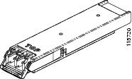
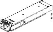
XFP Specifications
The following table lists specifications for available XFPs.
Important notes for the following table:
-
The ONS-XC-10G-L2 XFP installed on a transponder card, must be installed in high-speed slots 5, 6, 12, or 13 for power dissipation when FTA-3 or FTA-48V is used. There is no restriction on the slots in which the ONS-XC-10G-L2-FXP is installed when CC-FTA is used.
-
The IB_5G payload is supported by ONS-XC-10G-S1 XFP P/N version 03 only.
|
XFP |
Interface |
Transmitter Output Power Min/Max (dBm) |
Receiver Input Power Min/Max (dBm) |
|---|---|---|---|
|
ONS-XC-8G-MM= |
OC192/STM64/8GFC |
–8.2 to –1.5 |
0.151 mW (stressed received in OMA) |
|
ONS-XC-8G-SM= |
OC192/STM64/8GFC |
–8.4 to +0.5 |
–13.8 (–11.8 stressed) to +0.5 (targeting up to 10 km distance) |
|
ONS-XC-10G-C= |
OC-192/STM-64/10GE/10GFC/OTU2/IB_5G |
0 to +3 |
–24 to –7 |
|
ONS-XC-10G-I2= |
OC-192/STM-64/10GE/10GFC/OTU2 |
–1 to +2 |
–14 to +2 |
|
ONS-XC-10G-L2= |
OC-192/STM-64/10GE/10GFC/OTU2 |
0 to +4 |
–24 to –7 |
|
ONS-XC-10G-S1= |
OC-192/STM64/10GE/10GFC/IB_5G |
–6 to –1 –8.2 to +0.5 |
–11 to –1 –14.4 to +0.5 |
|
ONS-XC-10G-SR-MM= |
OC-192/STM-64/10GE/10GFC/OTU2 |
–7.3 to –1 |
–9.9 to –1 |
|
ONS-XC-10G-30.3= |
OC-192/STM-64/10GE/10GFC/OTU2/IB_5G |
–1 to +3 |
–23 to –7 |
|
ONS-XC-10G-31.1= |
OC-192/STM-64/10GE/10GFC/OTU2/IB_5G |
–1 to +3 |
–23 to –7 |
|
ONS-XC-10G-31.9= |
OC-192/STM-64/10GE/10GFC/OTU2/IB_5G |
–1 to +3 |
–23 to –7 |
|
ONS-XC-10G-32.6= |
OC-192/STM-64/10GE/10GFC/OTU2/IB_5G |
–1 to +3 |
–23 to –7 |
|
ONS-XC-10G-33.4= |
OC-192/STM-64/10GE/10GFC/OTU2/IB_5G |
–1 to +3 |
–23 to –7 |
|
ONS-XC-10G-34.2= |
OC-192/STM-64/10GE/10GFC/OTU2/IB_5G |
–1 to +3 |
–23 to –7 |
|
ONS-XC-10G-35.0= |
OC-192/STM-64/10GE/10GFC/OTU2/IB_5G |
–1 to +3 |
–23 to –7 |
|
ONS-XC-10G-35.8= |
OC-192/STM-64/10GE/10GFC/OTU2/IB_5G |
–1 to +3 |
–23 to –7 |
|
ONS-XC-10G-36.6= |
OC-192/STM-64/10GE/10GFC/OTU2/IB_5G |
–1 to +3 |
–23 to –7 |
|
ONS-XC-10G-37.4= |
OC-192/STM-64/10GE/10GFC/OTU2/IB_5G |
–1 to +3 |
–23 to –7 |
|
ONS-XC-10G-38.1= |
OC-192/STM-64/10GE/10GFC/OTU2/IB_5G |
–1 to +3 |
–23 to –7 |
|
ONS-XC-10G-38.9= |
OC-192/STM-64/10GE/10GFC/OTU2/IB_5G |
–1 to +3 |
–23 to –7 |
|
ONS-XC-10G-39.7= |
OC-192/STM-64/10GE/10GFC/OTU2/IB_5G |
–1 to +3 |
–23 to –7 |
|
ONS-XC-10G-40.5= |
OC-192/STM-64/10GE/10GFC/OTU2/IB_5G |
–1 to +3 |
–23 to –7 |
|
ONS-XC-10G-41.3= |
OC-192/STM-64/10GE/10GFC/OTU2/IB_5G |
–1 to +3 |
–23 to –7 |
|
ONS-XC-10G-42.1= |
OC-192/STM-64/10GE/10GFC/OTU2/IB_5G |
–1 to +3 |
–23 to –7 |
|
ONS-XC-10G-42.9= |
OC-192/STM-64/10GE/10GFC/OTU2/IB_5G |
–1 to +3 |
–23 to –7 |
|
ONS-XC-10G-43.7= |
OC-192/STM-64/10GE/10GFC/OTU2/IB_5G |
–1 to +3 |
–23 to –7 |
|
ONS-XC-10G-44.5= |
OC-192/STM-64/10GE/10GFC/OTU2/IB_5G |
–1 to +3 |
–23 to –7 |
|
ONS-XC-10G-45.3= |
OC-192/STM-64/10GE/10GFC/OTU2/IB_5G |
–1 to +3 |
–23 to –7 |
|
ONS-XC-10G-46.1= |
OC-192/STM-64/10GE/10GFC/OTU2/IB_5G |
–1 to +3 |
–23 to –7 |
|
ONS-XC-10G-46.9= |
OC-192/STM-64/10GE/10GFC/OTU2/IB_5G |
–1 to +3 |
–23 to –7 |
|
ONS-XC-10G-47.7= |
OC-192/STM-64/10GE/10GFC/OTU2/IB_5G |
–1 to +3 |
–23 to –7 |
|
ONS-XC-10G-48.5= |
OC-192/STM-64/10GE/10GFC/OTU2/IB_5G |
–1 to +3 |
–23 to –7 |
|
ONS-XC-10G-49.3= |
OC-192/STM-64/10GE/10GFC/OTU2/IB_5G |
–1 to +3 |
–23 to –7 |
|
ONS-XC-10G-50.1= |
OC-192/STM-64/10GE/10GFC/OTU2/IB_5G |
–1 to +3 |
–23 to –7 |
|
ONS-XC-10G-50.9= |
OC-192/STM-64/10GE/10GFC/OTU2/IB_5G |
–1 to +3 |
–23 to –7 |
|
ONS-XC-10G-51.7= |
OC-192/STM-64/10GE/10GFC/OTU2/IB_5G |
–1 to +3 |
–23 to –7 |
|
ONS-XC-10G-52.5= |
OC-192/STM-64/10GE/10GFC/OTU2/IB_5G |
–1 to +3 |
–23 to –7 |
|
ONS-XC-10G-53.3= |
OC-192/STM-64/10GE/10GFC/OTU2/IB_5G |
–1 to +3 |
–23 to –7 |
|
ONS-XC-10G-54.1= |
OC-192/STM-64/10GE/10GFC/OTU2/IB_5G |
–1 to +3 |
–23 to –7 |
|
ONS-XC-10G-54.9= |
OC-192/STM-64/10GE/10GFC/OTU2/IB_5G |
–1 to +3 |
–23 to –7 |
|
ONS-XC-10G-55.7= |
OC-192/STM-64/10GE/10GFC/OTU2/IB_5G |
–1 to +3 |
–23 to –7 |
|
ONS-XC-10G-56.5= |
OC-192/STM-64/10GE/10GFC/OTU2/IB_5G |
–1 to +3 |
–23 to –7 |
|
ONS-XC-10G-57.3= |
OC-192/STM-64/10GE/10GFC/OTU2/IB_5G |
–1 to +3 |
–23 to –7 |
|
ONS-XC-10G-58.1= |
OC-192/STM-64/10GE/10GFC/OTU2/IB_5G |
–1 to +3 |
–23 to –7 |
|
ONS-XC-10G-58.9= |
OC-192/STM-64/10GE/10GFC/OTU2/IB_5G |
–1 to +3 |
–23 to –7 |
|
ONS-XC-10G-59.7= |
OC-192/STM-64/10GE/10GFC/OTU2/IB_5G |
–1 to +3 |
–23 to –7 |
|
ONS-XC-10G-60.6= |
OC-192/STM-64/10GE/10GFC/OTU2/IB_5G |
–1 to +3 |
–23 to –7 |
|
ONS-XC-10G-61.4= |
OC-192/STM-64/10GE/10GFC/OTU2/IB_5G |
–1 to +3 |
–23 to –7 |
|
ONS-XC-10G-1470= |
OC-192/STM-64/10GE/10GFC/OTU2 |
+3 to +7 |
–14 to –0 |
|
ONS-XC-10G-1490= |
OC-192/STM-64/10GE/10GFC/OTU2 |
+3 to +7 |
–14 to –0 |
|
ONS-XC-10G-1510= |
OC-192/STM-64/10GE/10GFC/OTU2 |
+3 to +7 |
–14 to –0 |
|
ONS-XC-10G-1530= |
OC-192/STM-64/10GE/10GFC/OTU2 |
+3 to +7 |
–14 to –0 |
|
ONS-XC-10G-1550= |
OC-192/STM-64/10GE/10GFC/OTU2 |
+3 to +7 |
–14 to –0 |
|
ONS-XC-10G-1570= |
OC-192/STM-64/10GE/10GFC/OTU2 |
+3 to +7 |
–14 to –0 |
|
ONS-XC-10G-1590= |
OC-192/STM-64/10GE/10GFC/OTU2 |
+3 to +7 |
–14 to –0 |
|
ONS-XC-10G-1610= |
OC-192/STM-64/10GE/10GFC/OTU2 |
+3 to +7 |
–14 to –0 |
|
ONS-XC-10G-EP30.3= |
OC-192/STM-64/10GE/10GFC/OTU2 |
–1 to +3 |
–27 to –8 |
|
ONS-XC-10G-EP31.1= |
OC-192/STM-64/10GE/10GFC/OTU2 |
–1 to +3 |
–27 to –8 |
|
ONS-XC-10G-EP31.9= |
OC-192/STM-64/10GE/10GFC/OTU2 |
–1 to +3 |
–27 to –8 |
|
ONS-XC-10G-EP32.6= |
OC-192/STM-64/10GE/10GFC/OTU2 |
–1 to +3 |
–27 to –8 |
|
ONS-XC-10G-EP33.4= |
OC-192/STM-64/10GE/10GFC/OTU2 |
–1 to +3 |
–27 to –8 |
|
ONS-XC-10G-EP34.2= |
OC-192/STM-64/10GE/10GFC/OTU2 |
–1 to +3 |
–27 to –8 |
|
ONS-XC-10G-EP35.0= |
OC-192/STM-64/10GE/10GFC/OTU2 |
–1 to +3 |
–27 to –8 |
|
ONS-XC-10G-EP35.8= |
OC-192/STM-64/10GE/10GFC/OTU2 |
–1 to +3 |
–27 to –8 |
|
ONS-XC-10G-EP36.6= |
OC-192/STM-64/10GE/10GFC/OTU2 |
–1 to +3 |
–27 to –8 |
|
ONS-XC-10G-EP37.4= |
OC-192/STM-64/10GE/10GFC/OTU2 |
–1 to +3 |
–27 to –8 |
|
ONS-XC-10G-EP38.1= |
OC-192/STM-64/10GE/10GFC/OTU2 |
–1 to +3 |
–27 to –8 |
|
ONS-XC-10G-EP38.9= |
OC-192/STM-64/10GE/10GFC/OTU2 |
–1 to +3 |
–27 to –8 |
|
ONS-XC-10G-EP39.7= |
OC-192/STM-64/10GE/10GFC/OTU2 |
–1 to +3 |
–27 to –8 |
|
ONS-XC-10G-EP40.5= |
OC-192/STM-64/10GE/10GFC/OTU2 |
–1 to +3 |
–27 to –8 |
|
ONS-XC-10G-EP41.3= |
OC-192/STM-64/10GE/10GFC/OTU2 |
–1 to +3 |
–27 to –8 |
|
ONS-XC-10G-EP42.1= |
OC-192/STM-64/10GE/10GFC/OTU2 |
–1 to +3 |
–27 to –8 |
|
ONS-XC-10G-EP42.9= |
OC-192/STM-64/10GE/10GFC/OTU2 |
–1 to +3 |
–27 to –8 |
|
ONS-XC-10G-EP43.7= |
OC-192/STM-64/10GE/10GFC/OTU2 |
–1 to +3 |
–27 to –8 |
|
ONS-XC-10G-EP44.5= |
OC-192/STM-64/10GE/10GFC/OTU2 |
–1 to +3 |
–27 to –8 |
|
ONS-XC-10G-EP45.3= |
OC-192/STM-64/10GE/10GFC/OTU2 |
–1 to +3 |
–27 to –8 |
|
ONS-XC-10G-EP46.1= |
OC-192/STM-64/10GE/10GFC/OTU2 |
–1 to +3 |
–27 to –8 |
|
ONS-XC-10G-EP46.9= |
OC-192/STM-64/10GE/10GFC/OTU2 |
–1 to +3 |
–27 to –8 |
|
ONS-XC-10G-EP47.7= |
OC-192/STM-64/10GE/10GFC/OTU2 |
–1 to +3 |
–27 to –8 |
|
ONS-XC-10G-EP48.5= |
OC-192/STM-64/10GE/10GFC/OTU2 |
–1 to +3 |
–27 to –8 |
|
ONS-XC-10G-EP49.3= |
OC-192/STM-64/10GE/10GFC/OTU2 |
–1 to +3 |
–27 to –8 |
|
ONS-XC-10G-EP50.1= |
OC-192/STM-64/10GE/10GFC/OTU2 |
–1 to +3 |
–27 to –8 |
|
ONS-XC-10G-EP50.9= |
OC-192/STM-64/10GE/10GFC/OTU2 |
–1 to +3 |
–27 to –8 |
|
ONS-XC-10G-EP51.7= |
OC-192/STM-64/10GE/10GFC/OTU2 |
–1 to +3 |
–27 to –8 |
|
ONS-XC-10G-EP52.5= |
OC-192/STM-64/10GE/10GFC/OTU2 |
–1 to +3 |
–27 to –8 |
|
ONS-XC-10G-EP53.3= |
OC-192/STM-64/10GE/10GFC/OTU2 |
–1 to +3 |
–27 to –8 |
|
ONS-XC-10G-EP54.1= |
OC-192/STM-64/10GE/10GFC/OTU2 |
–1 to +3 |
–27 to –8 |
|
ONS-XC-10G-EP54.9= |
OC-192/STM-64/10GE/10GFC/OTU2 |
–1 to +3 |
–27 to –8 |
|
ONS-XC-10G-EP55.7= |
OC-192/STM-64/10GE/10GFC/OTU2 |
–1 to +3 |
–27 to –8 |
|
ONS-XC-10G-EP56.5= |
OC-192/STM-64/10GE/10GFC/OTU2 |
–1 to +3 |
–27 to –8 |
|
ONS-XC-10G-EP57.3= |
OC-192/STM-64/10GE/10GFC/OTU2 |
–1 to +3 |
–27 to –8 |
|
ONS-XC-10G-EP58.1= |
OC-192/STM-64/10GE/10GFC/OTU2 |
–1 to +3 |
–27 to –8 |
|
ONS-XC-10G-EP58.9= |
OC-192/STM-64/10GE/10GFC/OTU2 |
–1 to +3 |
–27 to –8 |
|
ONS-XC-10G-EP59.7= |
OC-192/STM-64/10GE/10GFC/OTU2 |
–1 to +3 |
–27 to –8 |
|
ONS-XC-10G-EP60.6= |
OC-192/STM-64/10GE/10GFC/OTU2 |
–1 to +3 |
–27 to –8 |
|
ONS-XC-10G-EP61.4= |
OC-192/STM-64/10GE/10GFC/OTU2 |
–1 to +3 |
–27 to –8 |
Single-Mode Fiber XFP Port Cabling Specifications
The following table lists specifications for single-mode fiber XFP port cabling.
Important note for the following table:
-
In CTC card view, ONS-XC-10G-1530 XFP shows the supported wavelength as 1530.33 nm. When you try to set the wavelength as 1530 nm, the PROV-MISMATCH alarm is raised.
|
XFP |
Wavelength |
Fiber Type |
Cable Distance |
|---|---|---|---|
|
ONS-XC-8G-SM= |
1550 nm |
SMF |
— |
|
ONS-XC-10G-C= |
1529.55 nm through 1561.83 nm, with ITU spacing |
SMF |
80 km (49.71 miles) for OC-192/STM64/10GE |
|
ONS-XC-10G-I2= |
Receiver: 1260 nm to 1565 nm Transmitter: 1530 nm to 1565 nm |
SMF |
40 km (25.80 miles) for OC-192/STM64 |
|
ONS-XC-10G-L2= |
Transmitter: 1530 nm to 1565 nm Receiver: 1260 nm to 1565 nm |
SMF |
80 km (49.71 miles) for OC-192/STM64 |
|
ONS-XC-10G-S1= |
1310 nm |
SMF |
10 km (6.2 miles) for 10GE/10GFC 2 km (1.2 miles) for OC-192/STM64 |
|
ONS-XC-10G-29.9= |
1529.95 nm |
SMF |
80 km (49.71 miles) for OC-192/STM64 |
|
ONS-XC-10G-30.3= |
1530.33 nm |
SMF |
80 km (49.71 miles) for OC-192/STM64 |
|
ONS-XC-10G-31.1= |
1531.12 nm |
SMF |
80 km (49.71 miles) for OC-192/STM64 |
|
ONS-XC-10G-31.9= |
1531.90 nm |
SMF |
80 km (49.71 miles) for OC-192/STM64 |
|
ONS-XC-10G-32.6= |
1532.68 nm |
SMF |
80 km (49.71 miles) for OC-192/STM64 |
|
ONS-XC-10G-33.4= |
1533.47 nm |
SMF |
80 km (49.71 miles) for OC-192/STM64 |
|
ONS-XC-10G-34.2= |
1534.25 nm |
SMF |
80 km (49.71 miles) for OC-192/STM64 |
|
ONS-XC-10G-35.0= |
1535.04 nm |
SMF |
80 km (49.71 miles) for OC-192/STM64 |
|
ONS-XC-10G-35.8= |
1535.82 nm |
SMF |
80 km (49.71 miles) for OC-192/STM64 |
|
ONS-XC-10G-36.6= |
1536.61 nm |
SMF |
80 km (49.71 miles) for OC-192/STM64 |
|
ONS-XC-10G-37.4= |
1537.40 nm |
SMF |
80 km (49.71 miles) for OC-192/STM64 |
|
ONS-XC-10G-38.1= |
1538.19 nm |
SMF |
80 km (49.71 miles) for OC-192/STM64 |
|
ONS-XC-10G-38.9= |
1538.98 nm |
SMF |
80 km (49.71 miles) for OC-192/STM64 |
|
ONS-XC-10G-39.7= |
1539.77 nm |
SMF |
80 km (49.71 miles) for OC-192/STM64 |
|
ONS-XC-10G-40.5= |
1540.56 nm |
SMF |
80 km (49.71 miles) for OC-192/STM64 |
|
ONS-XC-10G-41.3= |
1541.35 nm |
SMF |
80 km (49.71 miles) for OC-192/STM64 |
|
ONS-XC-10G-42.1= |
1542.14 nm |
SMF |
80 km (49.71 miles) for OC-192/STM64 |
|
ONS-XC-10G-42.9= |
1542.94 nm |
SMF |
80 km (49.71 miles) for OC-192/STM64 |
|
ONS-XC-10G-43.7= |
1543.73 nm |
SMF |
80 km (49.71 miles) for OC-192/STM64 |
|
ONS-XC-10G-44.5= |
1544.53 nm |
SMF |
80 km (49.71 miles) for OC-192/STM64 |
|
ONS-XC-10G-45.3= |
1545.32 nm |
SMF |
80 km (49.71 miles) for OC-192/STM64 |
|
ONS-XC-10G-46.1= |
1546.12 nm |
SMF |
80 km (49.71 miles) for OC-192/STM64 |
|
ONS-XC-10G-46.9= |
1546.92 nm |
SMF |
80 km (49.71 miles) for OC-192/STM64 |
|
ONS-XC-10G-47.7= |
1547.72 nm |
SMF |
80 km (49.71 miles) for OC-192/STM64 |
|
ONS-XC-10G-48.5= |
1548.51 nm |
SMF |
80 km (49.71 miles) for OC-192/STM64 |
|
ONS-XC-10G-49.3= |
1549.32 nm |
SMF |
80 km (49.71 miles) for OC-192/STM64 |
|
ONS-XC-10G-50.1= |
1550.12 nm |
SMF |
80 km (49.71 miles) for OC-192/STM64 |
|
ONS-XC-10G-50.9= |
1550.92 nm |
SMF |
80 km (49.71 miles) for OC-192/STM64 |
|
ONS-XC-10G-51.7= |
1551.72 nm |
SMF |
80 km (49.71 miles) for OC-192/STM64 |
|
ONS-XC-10G-52.5= |
1552.52 nm |
SMF |
80 km (49.71 miles) for OC-192/STM64 |
|
ONS-XC-10G-53.3= |
1553.33 nm |
SMF |
80 km (49.71 miles) for OC-192/STM64 |
|
ONS-XC-10G-54.1= |
1554.13 nm |
SMF |
80 km (49.71 miles) for OC-192/STM64 |
|
ONS-XC-10G-54.9= |
1554.94 nm |
SMF |
80 km (49.71 miles) for OC-192/STM64 |
|
ONS-XC-10G-55.7= |
1555.75 nm |
SMF |
80 km (49.71 miles) for OC-192/STM64 |
|
ONS-XC-10G-56.5= |
1556.55 nm |
SMF |
80 km (49.71 miles) for OC-192/STM64 |
|
ONS-XC-10G-57.3= |
1557.36 nm |
SMF |
80 km (49.71 miles) for OC-192/STM64 |
|
ONS-XC-10G-58.1= |
1558.17 nm |
SMF |
80 km (49.71 miles) for OC-192/STM64 |
|
ONS-XC-10G-58.9= |
1558.98 nm |
SMF |
80 km (49.71 miles) for OC-192/STM64 |
|
ONS-XC-10G-59.7= |
1559.79 nm |
SMF |
80 km (49.71 miles) for OC-192/STM64 |
|
ONS-XC-10G-60.6= |
1560.61 nm |
SMF |
80 km (49.71 miles) for OC-192/STM64 |
|
ONS-XC-10G-61.4= |
1561.43 nm |
SMF |
80 km (49.71 miles) for OC-192/STM64 |
|
ONS-XC-10G-1470= |
1470 nm |
SMF |
40 km (25.80 miles) for OTU2 and 10GE 10 km (6.2 miles) for OC192/STM64 |
|
ONS-XC-10G-1490= |
1490 nm |
SMF |
40 km (25.80 miles) for OTU2 and 10GE 10 km (6.2 miles) for OC192/STM64 |
|
ONS-XC-10G-1510= |
1510 nm |
SMF |
40 km (25.80 miles) for OTU2 and 10GE 10 km (6.2 miles) for OC192/STM64 |
|
ONS-XC-10G-1530= |
1530 nm |
SMF |
40 km (25.80 miles) for OTU2 and 10GE 10 km (6.2 miles) for OC192/STM64 |
|
ONS-XC-10G-1550= |
1550 nm |
SMF |
40 km (25.80 miles) for OTU2 and 10GE 10 km (6.2 miles) for OC192/STM64 |
|
ONS-XC-10G-1570= |
1570 nm |
SMF |
40 km (25.80 miles) for OTU2 and 10GE 10 km (6.2 miles) for OC192/STM64 |
|
ONS-XC-10G-1590= |
1590 nm |
SMF |
40 km (25.80 miles) for OTU2 and 10GE 10 km (6.2 miles) for OC192/STM64 |
|
ONS-XC-10G-1610= |
1610 nm |
SMF |
40 km (25.80 miles) for OTU2 and 10GE 10 km (6.2 miles) for OC192/STM64 |
|
ONS-XC-10G-EP30.3= |
1530.33 nm |
SMF |
50 km (31.1 miles) |
|
ONS-XC-10G-EP31.1= |
1531.12 nm |
SMF |
50 km (31.1 miles) |
|
ONS-XC-10G-EP31.9= |
1531.90 nm |
SMF |
50 km (31.1 miles) |
|
ONS-XC-10G-EP32.6= |
1532.68 nm |
SMF |
50 km (31.1 miles) |
|
ONS-XC-10G-EP33.4= |
1533.47 nm |
SMF |
50 km (31.1 miles) |
|
ONS-XC-10G-EP34.2= |
1534.25 nm |
SMF |
50 km (31.1 miles) |
|
ONS-XC-10G-EP35.0= |
1535.04 nm |
SMF |
50 km (31.1 miles) |
|
ONS-XC-10G-EP35.8= |
1535.82 nm |
SMF |
50 km (31.1 miles) |
|
ONS-XC-10G-EP36.6= |
1536.61 nm |
SMF |
50 km (31.1 miles) |
|
ONS-XC-10G-EP37.4= |
1537.40 nm |
SMF |
50 km (31.1 miles) |
|
ONS-XC-10G-EP38.1= |
1538.19 nm |
SMF |
50 km (31.1 miles) |
|
ONS-XC-10G-EP38.9= |
1538.98 nm |
SMF |
50 km (31.1 miles) |
|
ONS-XC-10G-EP39.7= |
1539.77 nm |
SMF |
50 km (31.1 miles) |
|
ONS-XC-10G-EP40.5= |
1540.56 nm |
SMF |
50 km (31.1 miles) |
|
ONS-XC-10G-EP41.3= |
1541.35 nm |
SMF |
50 km (31.1 miles) |
|
ONS-XC-10G-EP42.1= |
1542.14 nm |
SMF |
50 km (31.1 miles) |
|
ONS-XC-10G-EP42.9= |
1542.94 nm |
SMF |
50 km (31.1 miles) |
|
ONS-XC-10G-EP43.7= |
1543.73 nm |
SMF |
50 km (31.1 miles) |
|
ONS-XC-10G-EP44.5= |
1544.53 nm |
SMF |
50 km (31.1 miles) |
|
ONS-XC-10G-EP45.3= |
1545.32 nm |
SMF |
50 km (31.1 miles) |
|
ONS-XC-10G-EP46.1= |
1546.12 nm |
SMF |
50 km (31.1 miles) |
|
ONS-XC-10G-EP46.9= |
1546.92 nm |
SMF |
50 km (31.1 miles) |
|
ONS-XC-10G-EP47.7= |
1547.72 nm |
SMF |
50 km (31.1 miles) |
|
ONS-XC-10G-EP48.5= |
1548.51 nm |
SMF |
50 km (31.1 miles) |
|
ONS-XC-10G-EP49.3= |
1549.32 nm |
SMF |
50 km (31.1 miles) |
|
ONS-XC-10G-EP50.1= |
1550.12 nm |
SMF |
50 km (31.1 miles) |
|
ONS-XC-10G-EP50.9= |
1550.92 nm |
SMF |
50 km (31.1 miles) |
|
ONS-XC-10G-EP51.7= |
1551.72 nm |
SMF |
50 km (31.1 miles) |
|
ONS-XC-10G-EP52.5= |
1552.52 nm |
SMF |
50 km (31.1 miles) |
|
ONS-XC-10G-EP53.3= |
1553.33 nm |
SMF |
50 km (31.1 miles) |
|
ONS-XC-10G-EP54.1= |
1554.13 nm |
SMF |
50 km (31.1 miles) |
|
ONS-XC-10G-EP54.9= |
1554.94 nm |
SMF |
50 km (31.1 miles) |
|
ONS-XC-10G-EP55.7= |
1555.75 nm |
SMF |
50 km (31.1 miles) |
|
ONS-XC-10G-EP56.5= |
1556.55 nm |
SMF |
50 km (31.1 miles) |
|
ONS-XC-10G-EP57.3= |
1557.36 nm |
SMF |
50 km (31.1 miles) |
|
ONS-XC-10G-EP58.1= |
1558.17 nm |
SMF |
50 km (31.1 miles) |
|
ONS-XC-10G-EP58.9= |
1558.98 nm |
SMF |
50 km (31.1 miles) |
|
ONS-XC-10G-EP59.7= |
1559.79 nm |
SMF |
50 km (31.1 miles) |
|
ONS-XC-10G-EP60.6= |
1560.61 nm |
SMF |
50 km (31.1 miles) |
|
ONS-XC-10G-EP61.4= |
1561.43 nm |
SMF |
50 km (31.1 miles) |
Multimode Fiber XFP Port Cabling Specifications
The following table lists specifications for multimode fiber XFP port cabling.
|
XFP |
Wavelength |
Fiber Type |
Cable Distance |
|---|---|---|---|
|
ONS-XC-8G-MM= |
840 nm to 860 nm |
MMF |
— |
|
ONS-XC-10G-SR-MM= |
840 nm to 860 nm |
MMF |
26-300 m (0.1864 miles) OC-192/STM64/10GE/10GFC/OTU2 |
CFP Description and Specifications
The C Form factor Pluggable (CFP) modules are hot-swappable I/O devices that plug into 40-Gigabit and 100-Gigabit Ethernet module ports. The CFP modules provide data rate up to 40 Gbps for ONS-CC-40G-LR4 or 100 Gbps for ONS-CC-100G-LR4.
CFP dimensions are:
-
Height 0.53 inches (1.36 cm)
-
Width 3.22 inches (8.2 cm)
-
Depth 5.7 inches (14.48 cm)
The CFP module operating temperature range between 23 degrees Fahrenheit to 158 degrees Fahrenheit (–5 degrees Celsius to 70 degrees Celsius).
The 100 Gbps signal is carried over four wavelengths ( 1295.6 nm, 1300.1 nm, 1304.6 nm, and 1309.1 nm). Multiplexing and demultiplexing of the four wavelengths are managed within the device. The 40 Gbps signal is carried over four wavelengths ( 1271 nm, 1291 nm, 1311 nm, and 1331 nm). Multiplexing and demultiplexing of the four wavelengths are managed within the device.
The following figure shows a CFP module with a 12-fiber MPO connector.
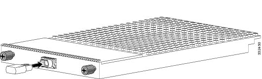
|
1 |
Captive installation screws |
3 |
Transmit and receive multifiber optical bore, MPO/MTP connector |
|
2 |
Optical bore dust plug |
Note |
The MPO connectors on the optical CFP transceivers support network interface cables with either Physical Contact (PC) or Ultra-Physical Contact (UPC) flat polished face types. The MPO connectors on the optical CFP transceivers do not support network interface cables with an Angle Polished Connector (APC) polished face type. |
CFP Specifications
The following table lists specifications for available CFP modules.
|
CFP |
Interface |
Transmitter Output Power Min/Max (dBm) |
Receiver Input Power Min/Max (dBm) |
|---|---|---|---|
|
ONS-CC-100G-LR4= |
100GBASE-LR4 |
–4.3 to 4.5 per wavelength |
–10.6 to 4.5 per wavelength |
|
4I1-9D1-F |
–2.5 to 2.9 per wavelength |
2.9 to –8.8 per wavelength |
|
|
ONS-CC-100GE-LR4= |
100GBASE-LR4 |
–4.3 to 4.5 per wavelength |
–10.6 to 4.5 per wavelength |
|
ONS-CC-40G-LR4= |
40GBASE-LR4 |
–7 to 2.3 per wavelength |
–13.7 to 2.3 per wavelength |
|
C4S1_2D1 |
–2.3 to 2.3 per wavelength |
–9 to 2.3 per wavelength |
|
|
ONS-CC-40G-FR= |
40GBASE-FR |
0 to 3 |
–6 to 3 |
|
CFP-40G-SR4= |
40GBASE-SR4 |
–7.6 to 2.4 per wavelength |
–9.5 to 2.4 per wavelength |
Single-Mode Fiber CFP Port Cabling Specifications
The following table provides cabling specifications for the SMF CFPs.
|
CFP |
Wavelength (nm) |
Fiber Type |
Cable Distance |
|---|---|---|---|
|
ONS-CC-100G-LR4= |
1310 |
SMF |
10 km (6.2 miles) |
|
ONS-CC-40G-LR4= |
1310 |
SMF |
10 km (6.2 miles) |
|
ONS-CC-40G-FR= |
1530 |
SMF |
2 km (1.24 miles) |
Multimode Fiber CFP Port Cabling Specifications
The following table provides cabling specifications for the MMF CFP.
|
CFP |
Wavelength (nm) |
Fiber Type |
Cable Distance |
|---|---|---|---|
|
CFP-40G-SR4 |
850 |
MMF |
30 m (98.4 ft) for OM2 100 m (328 ft) for OM3 150 m (492.1 ft) for OM4 |
CFP2 Description and Specifications
The CFP2 module is a hot pluggable form factor designed for optical networking applications. The module size accommodates a wide range of power dissipations and applications. The module's electrical interface has been generically specified to support supplier-specific customization for various 4 x 25Gbit/s interfaces. It can also support 8x25Gbit/s, 10x10Gbit/s, and 8x50Gbit/s.
The CFP2 pluggable is based on the CFP2-ACO specification with a few modifications. The CFP2-ACO module contains all the required functions to perform bidirectional dual polarization coherent optical signaling over a pair of single mode optical fibers.
The key features of the CFP2 pluggable module:
-
Supports different modulation schemes - BPSK, QPSK, 8-QAM, 16-QAM (200G and 250G)
-
Tunable across the full C-Band, covering 96 Nyquist shaped channels on the 50-GHz grid or griddles with 100MHz tuning granularity per channel
-
Optical output power adjustable
-
Temperature range between –5 degree Celsius up to 75 degrees Celsius
-
Control management interface based on MDIO
-
CFP2 power class 5
-
Dual LC connector
|
CFP2 |
Interface |
Transmitter Output Power Min/Max (dBm) |
Receiver Input Power Min/Max (dBm) |
|---|---|---|---|
|
ONS-CFP2-WDM = |
Duplex LC |
–11.5 to –1.5 dBm |
–20 to 0 dBm |
|
ONS-CFP2D-400G-C |
400ZR, 300ZR, 200ZR |
–10 to –1 dBm |
–23 to +1 dBm |
|
CFP2 |
Wavelength (nm) |
Fiber Type |
Cable Distance |
|---|---|---|---|
|
ONS-CFP2-WDM= |
96 channels |
SMF |
Depends on the selected modulation format |
CXP Description and Specifications
The CXP pluggable transceiver modules has 12 dedicated transmit (Tx) channels and 12 receive (Rx) channels per transceiver with data rates up to 10.3125 Gbps and OTN rates up to 11.25 Gbps. The CXP module provides 2-wire serial (I2C) management interface and digital diagnostics, including Tx and Rx optical power monitoring per wavelength. The CXP module uses a 24-fiber MPO connector that supports bidirectional transmission across the fibers (12 Tx + 12 Rx). The following table lists the supported CXP-CFP MPO connectors:
|
Cable |
Description |
Distance |
|---|---|---|
|
ONS-CCC-100G-5= |
CXP-CFP MPO connector |
5 m (16.4 ft) |
|
ONS-CCC-100G-10= |
CXP-CFP MPO connector |
10 m (32.8 ft) |
|
ONS-CCC-100G-20= |
CXP-CFP MPO connector |
20 m (65.6 ft) |
The CXP module operating temperature range between 23 degrees Fahrenheit to 158 degrees Fahrenheit (–5 degrees Celsius to 70 degrees Celsius).
CXP Specifications
The following table lists specifications for available CXP.
|
CXP |
Interface |
Transmitter Output Power Min/Max (dBm) |
Receiver Input Power Min/Max (dBm) |
|---|---|---|---|
|
ONS-CXP-100G-SR10= |
100GBASE-SR10 |
–7.6 to –1 per wavelength |
–9.5 to 2.4 per wavelength |
CXP Port Cabling Specifications
The following table provides cabling specifications for the MMF CXP.
|
CXP |
Wavelength (nm) |
Fiber Type |
Cable Distance |
|---|---|---|---|
|
ONS-CXP-100G-SR10= |
840 – 860 |
50.0 micron OM3 |
100 m (328 ft) |
|
50.0 micron OM4 |
300 m (984 ft) |
CPAK Description and Specifications
The Cisco CPAK 100GBASE modules CPAK 100GBASE-LR4 and CPAK 100GBASE-SR10 provides a wide variety of high-density100 Gigabit connectivity solutions.
The Cisco CPAK 100GBASE-LR4 module supports link lengths of up to 10 km over standard single-mode fiber (SMF, G.652) operating at a nominal 25 Gbps per lane. The nominal power consumption is less than 5.5W.
The Cisco CPAK 100GBASE-SR10 module supports link lengths of 100m and 150m on laser-optimized OM3 and OM4 multi-fiber cables, respectively. The module delivers high-bandwidth 100 Gigabit links over 24-fiber ribbon cables terminated with MPO, MTP or both connectors. It can also be used in 10 x 10 Gigabit mode along with ribbon-to-duplex-fiber breakout cables for connectivity to ten 10GBASE-SR optical interfaces.
The Cisco CPAK 100GBASE-SR4 is a form factor transceiver module for a multi-mode fiber. It supports short wavelengths over 4 lanes in the 850-nm wavelength window terminated with a MPO-12 connector.
The maximum outer dimensions for the CPAK modules are (H x W x D): 11.6 x 34.8 x 101.2 mm (0.46 x 1.37 x 3.98 in). The Cisco CPAK modules weigh approximately 127 grams (4.48 oz.).
The environmental conditions and power requirements are:
|
Specification |
Value |
|---|---|
|
Storage temperature range |
-40 to 85°C (-40 to 185°F) |
|
CPAK 100GBASE-LR4 operating temperature range |
0 to 75°C (32 to 167°F) |
|
CPAK 100GBASE-SR10 operating temperature range |
0 to 70°C (32 to 158°F) |
|
CPAK 100GBASE-SR4 operating temperature range |
0 to 70°C (32 to 158°F) |
|
CPAK 100GBASE FR operating temperature range |
0 to 70°C (32 to 158°F) |
|
CPAK 100GBASE-LR4 power consumption at 70°C |
less than 6.75W maximum |
|
CPAK 100GBASE-SR10 power consumption at 70°C |
less than 4.5W maximum |
|
CPAK 100GBASE-SR4 power consumption at 70°C |
less than 8W maximum |
|
CPAK 100GBASE FR power consumption at 70°C |
less than 9W maximum |
The following table provides cabling specifications for the Cisco CPAK modules.
|
Module |
Description |
Distance |
|---|---|---|
|
CPAK 100GBASE-LR4 |
Single-mode, Dual SC /PC connector |
10 km |
|
CPAK 100GBASE-SR10 |
Multi-mode MPO-24 or MTP-24 connector |
100 m (OM3) 150 m (OM4) |
|
CPAK 100GBASE-SR4 |
Multi-mode, MPO-12 or MTP-12 connector |
0.5m to 70m (OM3 MMF) 0.5m to 100m (OM4 MMF) |
|
CPAK 100GBASE FR |
Single-mode, Dual SC /PC connector |
2 km |
The following table shows the primary optical characteristics for the Cisco CPAK 100GBASE modules.
|
Module |
Type |
Transmit Power (dBm) |
Receive Power (dBm) |
Transmit and Receive Center Wavelength Range (nm) |
||
|---|---|---|---|---|---|---|
|
Maximum |
Minimum |
Maximum |
Minimum |
|||
|
CPAK 100GBASE-LR4 |
100GBASE-LR4 1310 nm SMF |
4.5 per lane |
-4.3 per lane |
4.5 per lane |
-10.6 per lane |
Four lanes:
|
|
CPAK 100GBASE-SR10 |
100GBASE-SR10 850 nm MMF |
-1.0 per lane |
-7.6 per lane |
2.4 per lane |
-9.5 per lane |
Ten lanes: 840 to 860 nm |
|
CPAK 100GBASE-SR4 |
100GBASE-SR4 850 nm MMF |
2.4 per lane |
-8.4 per lane |
2.4 per lane |
-10.3 per lane |
840 to 860 nm |
|
CPAK-100GBASE FR |
100GBASE FR SMF |
4.0 per lane |
-2.4 per lane |
4.5 per lane |
-6.4 per lane |
One lane: 1304.5 to 1317.5 |
NTP-G324 Install, Provision, and Delete PPMs
 Warning |
GBICs, SFP, SFP+, XFP, CXP, CFP, and CPAK modules are Class I laser products. Statement 1008 |
Warning |
Invisible laser radiation could be emitted from the end of the unterminated fiber cable or connector. Do not stare into the beam directly with optical instruments. Viewing the laser output with certain optical instruments (for example, eye loupes, magnifiers, and microscopes) within a distance of 100 mm could pose an eye hazard. Statement 1056 |
Warning |
Ultimate disposal of this product should be handled according to all national laws and regulations. Statement 1040 |
Warning |
Use of controls, adjustments, or performing procedures other than those specified may result in hazardous radiation exposure. Statement 1057 |
Warning |
During this procedure, wear grounding wrist straps to avoid ESD damage to the card. Do not directly touch the backplane with your hand or any metal tool, or you could shock yourself. Statement 94 |
Warning |
Before you install, operate, or service the system, read the Site Preparation and Safety Guide. This guide contains important safety information you should know before working with the system. |
Warning |
Only trained and qualified personnel should be allowed to install, replace, or service this equipment. Statement 148 |
Warning |
To comply with the Telcordia GR-1089 NEBS standard for electromagnetic compatibility and safety, for Ethernet RJ-45 ports, use only shielded Ethernet cables that are grounded on both ends. In a NEBS installation, all Ethernet ports are limited to intra-building wiring. Statement 7012 |
Warning |
Ethernet ports are intra-building ports and are suitable only for connecting to shielded cabling grounded at both ends. Statement 1084 |
Caution |
Do not use GBICs, SFP, SFP+, XFP, CXP, CFP, and CPAK modules from third-party vendors. Cisco TAC does not support third-party vendor GBICs, SFP, SFP+, XFP, CXP, CFP, and CPAK modules. A third-party vendor GBICs, SFP, SFP+, XFP, CXP, CFP, and CPAK modules is any GBICs, SFP, SFP+, XFP, CXP, CFP, and CPAK module that is not sourced from Cisco directly, or via a Cisco Partner, or Cisco authorized seller. Cisco-sourced GBICs, SFP, SFP+, XFP, CXP, CFP, and CPAK modules can be identified by the Cisco label and logo. |
Note |
GBICs and SFPs must be matched on either end by type: SX to SX, LX/LH to LX/LH, or ZX to ZX (GBIC). |
Note |
The shelf should be equipped with a CC-FAN if the copper SFP is installed on a MXP_MR_10DME card. |
|
Purpose |
This task installs, provisions, and deletes PPMs (GBICs, SFP, SFP+, XFP, CXP, CFP, and CPAK modules) on the line cards. Because GBICs, SFP, SFP+, XFP, CXP, CFP, and CPAK modules are hot-swappable, they can be installed and removed while the card/shelf assembly is powered and running. |
|
Tools/Equipment |
|
|
Prerequisite Procedures |
"NTP-G179 Install the TXP, MXP, AR_MXP, AR_XP, 100G-LC-C, 10x10G-LC, CFP-LC, ADM-10G, and OTU2_XP Cards" task in the chapter "Provision Transponder and Muxponder Cards" of Cisco ONS 15454 DWDM Configuration Guide |
|
Required/As Needed |
As needed |
|
Onsite/Remote |
Onsite |
|
Security Level |
Provisioning or higher |
SUMMARY STEPS
- Install PPMs. Complete the necessary task as applicable:
- Provision the PPM. Complete the necessary task as applicable:
- Delete the PPM. Complete the necessary task as applicable:
DETAILED STEPS
|
Step 1 |
Install PPMs. Complete the necessary task as applicable: |
|
Step 2 |
Provision the PPM. Complete the necessary task as applicable: |
|
Step 3 |
Delete the PPM. Complete the necessary task as applicable: Stop. You have completed this procedure. |
DLP-G723 Install PPM on a Line Card
|
Purpose |
This task installs PPM on a line card. The PPMs provide a fiber interface to the card. |
|
Tools/Equipment |
|
|
Prerequisite Procedures |
"NTP-G179 Install the TXP, MXP, AR_MXP, AR_XP, 100G-LC-C, 10x10G-LC, CFP-LC, ADM-10G, and OTU2_XP Cards" task in the chapter "Provision Transponder and Muxponder Cards" of Cisco ONS 15454 DWDM Line Card Configuration Guide. |
|
Required/As Needed |
As needed |
|
Onsite/Remote |
Onsite |
|
Security Level |
Provisioning or higher |
Warning |
GBICs, SFP, SFP+, XFP, CXP, and CFP modules are Class I laser products. Statement 1008 |
Warning |
Because invisible laser radiation may be emitted from the aperture of the port when no cable is connected, avoid exposure to laser radiation and do not stare into open apertures. Statement 70 |
Warning |
Ultimate disposal of this product should be handled according to all national laws and regulations. Statement 1040 |
Warning |
Use of controls, adjustments, or performing procedures other than those specified may result in hazardous radiation exposure. Statement 1057 |
Warning |
To comply with the Telcordia GR-1089 NEBS standard for electromagnetic compatibility and safety, connect the serial high-speed WAN interface ports only to intra-building or unexposed wiring or cable. The intrabuilding cable must be shielded and the shield must be grounded at both ends. The intra-building port(s) of the equipment or subassembly must not be metallically connected to interfaces that connect to the OSP or its wiring. These interfaces are designed for use as intra-building interfaces only (Type 2 or Type 4 ports as described in GR-1089-CORE) and require isolation from the exposed OSP cabling. The addition of Primary Protectors is not sufficient protection in order to connect these interfaces metallically to OSP wiring. Statement 7003 |
Note |
|
SUMMARY STEPS
- Verify that the GBICs, SFP, SFP+, XFP, CXP, or CFP module is correct for your network. Ensure that you are installing compatible GBICs, SFP, SFP+, XFP, CXP, or CFP module, for example, SX to SX or LX/LH to LX/LH.
- Remove the PPM from its protective packaging.
- Check the label to verify that the PPM is the correct type for your network.
- Verify the type of PPM you are using:
- Install GBICs with clips. Perform the following:
- Install GBICs with a handle. Perform the following:
- Install the SFP, SFP+, XFP, or CXP module. Perform the following:
- Install CFP module. Perform the following:
- Install CFP2 module. Perform the following:
- Return to your originating procedure (NTP).
DETAILED STEPS
|
Step 1 |
Verify that the GBICs, SFP, SFP+, XFP, CXP, or CFP module is correct for your network. Ensure that you are installing compatible GBICs, SFP, SFP+, XFP, CXP, or CFP module, for example, SX to SX or LX/LH to LX/LH. |
||||||
|
Step 2 |
Remove the PPM from its protective packaging. |
||||||
|
Step 3 |
Check the label to verify that the PPM is the correct type for your network.
|
||||||
|
Step 4 |
Verify the type of PPM you are using: |
||||||
|
Step 5 |
Install GBICs with clips. Perform the following: |
||||||
|
Step 6 |
Install GBICs with a handle. Perform the following: |
||||||
|
Step 7 |
Install the SFP, SFP+, XFP, or CXP module. Perform the following:
|
||||||
|
Step 8 |
Install CFP module. Perform the following:
|
||||||
|
Step 9 |
Install CFP2 module. Perform the following:
|
||||||
|
Step 10 |
Return to your originating procedure (NTP). |
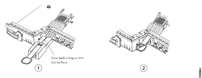
Installing the CFP2-DWDM Pluggable
To correctly insert the CFP2-DWDM pluggable, ensure the following:
-
The electrical connectors should be completely mated.
-
The latching mechanisms on both the sides of the pluggable should be fully engaged.
-
The pluggable is properly seated on the slot, by the application of a symmetrical force of at least 60N on its front surface, along the centerline. See the following figure for reference.
Figure 12. Inserting CFP2-DWDM Pluggable (face-up) 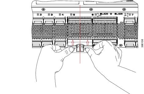
Figure 13. Inserting CFP2-DWDM Pluggable (face-down) 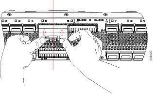
DLP-G724 Connecting Single-Mode and Multimode Optical Fiber
To connect the single-mode or multimode optical fiber, attach the appropriate optical fiber cable directly to the SC-type receptacle on the GBIC or the LC-type connector on the SFP, SFP+, or XFP module. You can use either simplex or duplex connectors for most devices. For simplex connectors, two cables are required, one cable for transmit (Tx) and a second cable for receive (Rx). For duplex connectors, only one cable that has both Tx and Rx connectors is required.
|
Purpose |
This task connects the single-mode or multimode optical fiber for GBICs, SFP, SFP+, and XFP modules installed on the line cards. |
|
Tools/Equipment |
None |
|
Prerequisite Procedures |
None |
|
Required/As Needed |
As needed |
|
Onsite/Remote |
Onsite |
|
Security Level |
Provisioning or higher |
SUMMARY STEPS
- Remove the protective plugs from the GBICs, SFP, SFP+, and XFP module and save them for future use.
- Remove the protective caps from the connectors on the fiber-optic cable and save them for future use.
- Clean fiber-optic connectors on fiber-optic cables.
- Plug the fiber-optic cable into the SC-type receptacle on the GBIC or the LC-type connector on the SFP, SFP+, or XFP module.
- Return to your originating procedure (NTP).
DETAILED STEPS
|
Step 1 |
Remove the protective plugs from the GBICs, SFP, SFP+, and XFP module and save them for future use. |
|
Step 2 |
Remove the protective caps from the connectors on the fiber-optic cable and save them for future use. |
|
Step 3 |
Clean fiber-optic connectors on fiber-optic cables. |
|
Step 4 |
Plug the fiber-optic cable into the SC-type receptacle on the GBIC or the LC-type connector on the SFP, SFP+, or XFP module. |
|
Step 5 |
Return to your originating procedure (NTP). |
DLP-G725 Preprovisioning PPM Slot
|
Purpose |
This task preprovisions PPM (GBIC, SFP, SFP+, XFP, CXP, or CFP) slot. |
|
Tools/Equipment |
None |
|
Prerequisite Procedures |
"DLP-G46 Log into CTC" in the Connect the PC and Log into the GUI document. |
|
Required/As Needed |
As needed |
|
Onsite/Remote |
Onsite or remote |
|
Security Level |
Provisioning or higher |
Note |
GBIC, SFP, SFP+, XFP, CXP, or CFP modules are generically called PPMs in CTC. After installing multirate GBIC, SFP, SFP+, XFP, CXP, or CFP modules, multirate PPMs must be provisioned in CTC. To complete the provisioning of the multirate pluggable port, complete the DLP-G726 Preprovisioning a Multirate PPM task. |
SUMMARY STEPS
- In node view (single-shelf mode) or shelf view (multishelf mode), double-click the card where you want to provision PPM settings.
- Click the Provisioning > Pluggable Port Modules tabs.
- In the Pluggable Port Modules area, click Create. The Create PPM dialog box appears.
- In the Create PPM dialog box, complete the following:
- Click OK. The newly created port appears in the Pluggable Port Modules pane. The row in the Pluggable Port Modules pane turns light blue. The Actual Equipment Type column remains blank until the actual GBIC, SFP, SFP+, XFP, CXP, or CFP module is installed. After the GBIC, SFP, SFP+, XFP, CXP, or CFP module is installed, the row in the pane turns white and the Actual Equipment Type column shows the equipment name.
- Verify that the PPM appears in the list in the Pluggable Port Modules pane. If it does not, repeat Step 3 through Step 5.
- Repeat Step 2 through Step 5 to provision a second PPM, if needed. If not, continue with Step 8.
- Click OK.
- Return to your originating procedure (NTP).
DETAILED STEPS
|
Step 1 |
In node view (single-shelf mode) or shelf view (multishelf mode), double-click the card where you want to provision PPM settings. |
||
|
Step 2 |
Click the Provisioning > Pluggable Port Modules tabs. |
||
|
Step 3 |
In the Pluggable Port Modules area, click Create. The Create PPM dialog box appears. |
||
|
Step 4 |
In the Create PPM dialog box, complete the following:
|
||
|
Step 5 |
Click OK. The newly created port appears in the Pluggable Port Modules pane. The row in the Pluggable Port Modules pane turns light blue. The Actual Equipment Type column remains blank until the actual GBIC, SFP, SFP+, XFP, CXP, or CFP module is installed. After the GBIC, SFP, SFP+, XFP, CXP, or CFP module is installed, the row in the pane turns white and the Actual Equipment Type column shows the equipment name.
|
||
|
Step 6 |
Verify that the PPM appears in the list in the Pluggable Port Modules pane. If it does not, repeat Step 3 through Step 5. |
||
|
Step 7 |
Repeat Step 2 through Step 5 to provision a second PPM, if needed. If not, continue with Step 8. |
||
|
Step 8 |
Click OK. |
||
|
Step 9 |
Return to your originating procedure (NTP). |
DLP-G726 Preprovisioning a Multirate PPM
|
Purpose |
This task provisions a multirate PPM on a line card. |
|
Tools/Equipment |
None |
|
Prerequisite Procedures |
"DLP-G46 Log into CTC" in the Connect the PC and Log into the GUI document. |
|
Required/As Needed |
As needed |
|
Onsite/Remote |
Onsite or remote |
|
Security Level |
Provisioning or higher |
Note |
If the PPM was preprovisioned using the DLP-G725 Preprovisioning PPM Slot task, this task is unnecessary, unless the PPM has an Out-of-Service and Autonomous Management, Unassigned (ANSI) or Unlocked-disabled, unassigned (ETSI) service state. |
SUMMARY STEPS
- In node view (single-shelf mode) or shelf view (multishelf view), double-click the line card where you want to provision the multirate PPM settings.
- If this is the first multirate PPM provisioned for the card, continue with Step 3. If not, complete the following steps.
- Click the Provisioning > Pluggable Port Modules tabs.
- In the Pluggable Port Modules area, click Create. The Create PPM dialog box appears.
- In the Create PPM dialog box, complete the following:
- Click OK. The newly created port appears in the Pluggable Port Modules area. The row in the Pluggable Port Modules area turns white and the Actual Equipment Type column lists the equipment name.
- If you want to provision a PPM on another port, repeat Step 3 through Step 5.
- Return to your originating procedure (NTP).
DETAILED STEPS
|
Step 1 |
In node view (single-shelf mode) or shelf view (multishelf view), double-click the line card where you want to provision the multirate PPM settings. |
|
Step 2 |
If this is the first multirate PPM provisioned for the card, continue with Step 3. If not, complete the following steps.
|
|
Step 3 |
Click the Provisioning > Pluggable Port Modules tabs. |
|
Step 4 |
In the Pluggable Port Modules area, click Create. The Create PPM dialog box appears. |
|
Step 5 |
In the Create PPM dialog box, complete the following:
|
|
Step 6 |
Click OK. The newly created port appears in the Pluggable Port Modules area. The row in the Pluggable Port Modules area turns white and the Actual Equipment Type column lists the equipment name. |
|
Step 7 |
If you want to provision a PPM on another port, repeat Step 3 through Step 5. |
|
Step 8 |
Return to your originating procedure (NTP). |
DLP-G727 Delete PPM Provisioning
-
Before deleting a PPM, delete the PPM from the provisioning pane.
-
This task does not apply to the TXP_MR_10G card. To change the TXP_MR_10G data rate, see the section "DLP-G365 Provision the TXP_MR_10G Data Rate" in the chapter "Provision Transponder and Muxponder Cards" of Cisco ONS 15454 DWDM Configuration Guide.
-
You cannot delete a PPM if the TXP, MXP, AR_MXP, AR_XP, GE_XP, 10GE_XP, GE_XPE, 10GE_XPE, or ADM-10G card is part of a regenerator group. For OTU2_XP card, you cannot delete a PPM if the card configuration is in Standard Regen or Enhanced FEC mode.
|
Purpose |
This task deletes PPM provisioning for GBICs, SFP, SFP+, XFP, CXP, and CFP modules installed on the line cards. |
|
Tools/Equipment |
None |
|
Prerequisite Procedures |
"DLP-G46 Log into CTC" in the Connect the PC and Log into the GUI document. |
|
Required/As Needed |
As needed |
|
Onsite/Remote |
Onsite or remote |
|
Security Level |
Provisioning or higher |
SUMMARY STEPS
- In node view (single-shelf mode) or shelf view (multishelf view), double-click the line card where you want to delete PPM settings.
- Verify that the PPM port Service State is OOS,DSBLD. If it is not OOS,DSBLD, follow the tasks in "NTP-G128 Manage Pluggable Port Modules" in the chapter "Provision Transponder and Muxponder Cards" of Cisco ONS 15454 DWDM Configuration Guide to change the Service State of the PPM port to OOS,DSBLD.
- Click the Provisioning > Pluggable Port Modules tabs.
- To delete a PPM and the associated ports, perform the following:
- Verify that the PPM provisioning is deleted:
- (Optional) If you need to remove the PPM hardware, complete the DLP-G728 Remove PPM from the Line Card.
- Return to your originating procedure (NTP).
DETAILED STEPS
|
Step 1 |
In node view (single-shelf mode) or shelf view (multishelf view), double-click the line card where you want to delete PPM settings. |
|
Step 2 |
Verify that the PPM port Service State is OOS,DSBLD. If it is not OOS,DSBLD, follow the tasks in "NTP-G128 Manage Pluggable Port Modules" in the chapter "Provision Transponder and Muxponder Cards" of Cisco ONS 15454 DWDM Configuration Guide to change the Service State of the PPM port to OOS,DSBLD. |
|
Step 3 |
Click the Provisioning > Pluggable Port Modules tabs. |
|
Step 4 |
To delete a PPM and the associated ports, perform the following: |
|
Step 5 |
Verify that the PPM provisioning is deleted:
|
|
Step 6 |
(Optional) If you need to remove the PPM hardware, complete the DLP-G728 Remove PPM from the Line Card. |
|
Step 7 |
Return to your originating procedure (NTP). |
DLP-G728 Remove PPM from the Line Card
|
Purpose |
This task removes PPMs from the line cards. |
|
Tools/Equipment |
|
|
Prerequisite Procedures |
None |
|
Required/As Needed |
As needed |
|
Onsite/Remote |
Onsite |
|
Security Level |
Provisioning or higher |
Warning |
GBICs, SFP, SFP+, XFP, CXP, and CFP modules are Class I laser products. Statement 1008 |
Warning |
Because invisible laser radiation may be emitted from the aperture of the port when no cable is connected, avoid exposure to laser radiation and do not stare into open apertures. Statement 70 |
Warning |
Ultimate disposal of this product should be handled according to all national laws and regulations. Statement 1040 |
Note |
|
SUMMARY STEPS
- Disconnect the network fiber cable from the PPM connector. If the GBICs, SFP, SFP+, XFP, CXP, and CFP connector has a latch securing the fiber cable, pull it upward to release the cable.
- Remove PPM. Perform the following as necessary:
- Remove GBIC with clips. Perform the following:
- Remove GBIC with a handle. Perform the following:
- Remove SFP, SFP+, or XFP module. Perform the following:
- Remove CFP module. Perform the following:
- Return to your originating procedure (NTP).
DETAILED STEPS
|
Step 1 |
Disconnect the network fiber cable from the PPM connector. If the GBICs, SFP, SFP+, XFP, CXP, and CFP connector has a latch securing the fiber cable, pull it upward to release the cable. |
||
|
Step 2 |
Remove PPM. Perform the following as necessary: |
||
|
Step 3 |
Remove GBIC with clips. Perform the following:
|
||
|
Step 4 |
Remove GBIC with a handle. Perform the following:
|
||
|
Step 5 |
Remove SFP, SFP+, or XFP module. Perform the following: |
||
|
Step 6 |
Remove CFP module. Perform the following:
|
||
|
Step 7 |
Return to your originating procedure (NTP). |
Related Documentation
Use this document in conjunction with the following referenced publications as needed:
-
Cisco ONS 15454 DWDM Configuration Guide
-
Cisco ONS 15454 DWDM Procedure Guide
-
Cisco ONS 15454 DWDM Reference Manual
-
Cisco ONS 15454 DWDM Troubleshooting Guide
-
Cisco ONS 15454 Procedure Guide
-
Cisco ONS 15454 Reference Manual
-
Cisco ONS 15454 Troubleshooting Guide
-
Cisco ONS 15454 SDH Procedure Guide
-
Cisco ONS 15454 SDH Reference Manual
-
Cisco ONS 15454 SDH Troubleshooting Guide
-
Cisco ONS 15310-CL and Cisco ONS 15310-MA Procedure Guide
-
Cisco ONS 15310-CL and Cisco ONS 15310-MA Reference Manual
-
Cisco ONS 15310-CL and Cisco ONS 15310-MA Troubleshooting Guide
-
Cisco ONS 15310-MA SDH Procedure Guide
-
Cisco ONS 15310-MA SDH Reference Manual
-
Cisco ONS 15310-MA SDH Troubleshooting Guide
-
Cisco ONS 15600 Procedure Guide
-
Cisco ONS 15600 Reference Manual
-
Cisco ONS 15600 Troubleshooting Guide
-
Cisco ONS 15600 SDH Procedure Guide
-
Cisco ONS 15600 SDH Reference Manual
-
Cisco ONS 15600 SDH Troubleshooting Guide
-
Regulatory Compliance and Safety Information for Cisco CPT and Cisco ONS Platforms
Additional References
Related Documents
Use this document in conjunction with the other release-specific documentation listed in this table:
| Link | Description |
|---|---|
| Cisco ONS Documentation Roadmap |
Provides quick access to publications of Cisco ONS releases. |
|
Cisco ONS 15454 DWDM Control Card and Node Configuration Guide |
Provides background and reference material and procedures for installation and configuration of control cards and node configuration on Cisco ONS 15454 dense wavelength division multiplexing (DWDM) systems. |
|
Cisco ONS 15454 DWDM Line Card Configuration Guide |
Provides background and reference material and procedures for installation and configuration of line cards on Cisco ONS 15454 dense wavelength division multiplexing (DWDM) systems. |
|
Cisco ONS 15454 DWDM Network Configuration Guide |
Provides background and reference material, procedures for turn up, provisioning, and maintenance of Cisco ONS 15454 dense wavelength division multiplexing (DWDM) systems. |
|
Cisco ONS 15454 DWDM Troubleshooting Guide |
Provides general troubleshooting instructions, alarm troubleshooting instructions, and a list of error messages that apply to the Cisco ONS 15454 dense wavelength division multiplexing (DWDM) systems. |
| Release Notes for Cisco ONS 15454 |
Provides information about new features and enhancements for the Cisco ONS 15454 DWDM platforms. |
| Cisco ONS 15454 Hardware Installation Guide |
Provides installation information of the Cisco ONS 15454 hardware. |
| Cisco ONS 15454 DWDM Licensing Guide |
Provides information about installing and managing Cisco ONS 15454 DWDM licenses. |
| Cisco ONS SDH TL1 Command Guide
Cisco ONS SONET TL1 Command Guide |
Provides a comprehensive list of TL1 commands. |
|
Installing the GBIC, SFP, SFP+, XFP, CXP, CFP, and CPAK Optical Modules in Cisco ONS Platforms |
Provides information about the Pluggable Port Modules support. |
| Link | Description |
|---|---|
|
Cisco NCS 2000 Series Documentation Roadmap |
Provides quick access to publications of Cisco NCS 2000 Series releases. |
|
Cisco NCS 2000 Series Control Card and Node Configuration Guide |
Provides background and reference material and procedures for installation and configuration of control cards and node configuration on Cisco NCS 2000 Series systems. |
|
Cisco NCS 2000 Series Line Card Configuration Guide |
Provides background and reference material and procedures for installation and configuration of line cards on Cisco NCS 2000 Series systems. |
|
Cisco NCS 2000 Series Network Configuration Guide |
Provides background and reference material, procedures for turn up, provisioning, and maintenance of Cisco NCS 2000 Series systems. |
|
Cisco NCS 2000 Series Troubleshooting Guide |
Provides general troubleshooting instructions, alarm troubleshooting instructions, and a list of error messages that apply to the Cisco NCS 2000 Series systems. |
|
Release Notes for Cisco NCS 2000 Series |
Provides information about new features and enhancements for the Cisco NCS 2000 Series systems. |
|
Cisco NCS 2000 Series Hardware Installation Guide |
Provides installation information of the Cisco NCS 2000 Series hardware. |
|
Cisco NCS 2000 Series Licensing Configuration Guide |
Provides information about installing and managing NCS licenses. |
|
Cisco NCS 2000 Series TL1 Command Guide |
Provides a comprehensive list of TL1 commands. |
|
Installing the GBIC, SFP, SFP+, XFP, CXP, CFP, and CPAK Optical Modules in Cisco NCS Platforms |
Provides information about the Pluggable Port Modules support. |
Technical Assistance
| Link | Description |
|---|---|
|
The Cisco Support website provides extensive online resources, including documentation and tools for troubleshooting and resolving technical issues with Cisco products and technologies. To receive security and technical information about your products, you can subscribe to various services, such as the Product Alert Tool (accessed from Field Notices), the Cisco Technical Services Newsletter, and Really Simple Syndication (RSS) Feeds. Access to most tools on the Cisco Support website requires a Cisco.com user ID and password. |
Short Description
Cisco and the Cisco logo are trademarks or registered trademarks of Cisco and/or its affiliates in the U.S. and other countries. To view a list of Cisco trademarks, go to this URL: https://www.cisco.com/c/en/us/about/legal/trademarks.html. Third-party trademarks mentioned are the property of their respective owners. The use of the word partner does not imply a partnership relationship between Cisco and any other company. (1721R)
Communications, Services, and Additional Information
-
To receive timely, relevant information from Cisco, sign up at Cisco Profile Manager.
-
To get the business impact you’re looking for with the technologies that matter, visit Cisco Services.
-
To submit a service request, visit Cisco Support.
-
To discover and browse secure, validated enterprise-class apps, products, solutions and services, visit Cisco DevNet.
-
To obtain general networking, training, and certification titles, visit Cisco Press.
-
To find warranty information for a specific product or product family, access Cisco Warranty Finder.
Cisco Bug Search Tool
Cisco Bug Search Tool (BST) is a web-based tool that acts as a gateway to the Cisco bug tracking system that maintains a comprehensive list of defects and vulnerabilities in Cisco products and software. BST provides you with detailed defect information about your products and software.
 Feedback