Installing the Switch
Available Languages
Table Of Contents
Install the Switch On a Desk or Shelf
Installing the Switch
Read this chapter for the guidelines and procedures to install the switch.
Before You Begin
Before you install the switch, review the information in the Release Notes for the Catalyst Express 520 Switches on Cisco.com.
Before you power or install the switch, review the safety information the "Warnings" section and the "Installation Guidelines" section.
The warnings in this chapter are translated into several languages in the Regulatory Compliance and Safety Information for the Catalyst Express 520 Switches document on Cisco.com.
Chapter Topics
•
Install the Switch On a Desk or Shelf
Warnings
These warnings are translated into several languages in the Regulatory Compliance and Safety Information for the Catalyst Express 520 Switches document that shipped with the switch. Review these warnings before you power or install the switch.

Warning
Warning
Warning
Warning
Warning
Warning
Warning
Statement 371—Power Cable and AC Adapter
Warning
Warning
.
Warning
Warning
Warning
Warning
Warning
Warning
Warning
Warning
Warning
Warning
Warning
Warning
Warning
Installation Guidelines
When determining where to place the switch, make sure to observe these requirements and guidelines. Use these requirements and guidelines with the information in "Reference."
•

Note
•
•
Note
•
•
•
•
•
–
–
–
–
•
•
For additional cabling guidelines, see the "Cabling Guidelines" section.
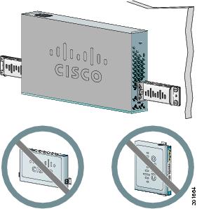
Install the Switch On a Desk or Shelf
Follow these steps:
Install the Switch in a Rack
Prerequisite
Installing the Catalyst Express 520-8PC-K9 switch in a 19-inch rack requires 19-inch rack-mounting brackets and hardware that are not shipped with the switch. You can order a bracket kit from Cisco. The kit part number is RCKMNT-19-CMPCT=.
The other Catalyst Express switches ship with brackets and hardware.
Follow these steps:
Install the Switch on a Wall
Prerequisites
•
The other Catalyst Express switches ship with brackets and hardware.
•
Follow these steps:
Step 1
If you are wall-mounting a Catalyst Express 520-8PC-K9 switch, order the bracket kit from Cisco. The kit part number is RCKMNT-19-CMPCT=.
For the other Catalyst Express switches, locate the brackets and hardware in the accessory kit.
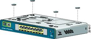
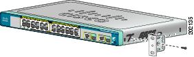
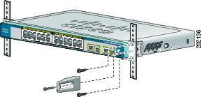
Step 2
Use the Phillips flat-head screws, included in the bracket kit, to attach a 19-inch bracket to each side of the switch.
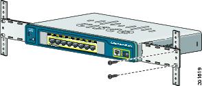
Step 3
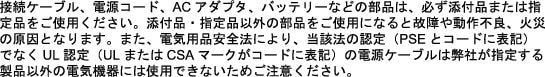
Mount the switch with the front panel facing down, and use your screws to attach the brackets to the wall as shown in Step 2.
For the best support of the switch and cables, make sure that the switch is attached securely to wall studs or to a firmly attached plywood mounting backboard.
Do not wall-mount the switch with its front panel facing up or sideways. According to safety regulations, wall-mount the switch with its front panel facing down to prevent airflow restriction and to provide easier access to the cables.
Step 4
Use the supplied switch power cable to connect the switch to an AC power source.
Step 5
Wait until the System LED blinks green and then turns solid green. A solid green SYSTEM LED means that the switch is operating properly.
Troubleshooting:
If the SYSTEM LED does not blink green, does not turn solid green, or turns amber, contact your Cisco representative or reseller. The switch failed the power-on self-test (POST).
When You Are Done
After you have installed the switch in your network, follow the procedures in "Connecting to the Switch," to properly connect other network devices to the switch. Make sure to review the warnings and installation guidelines.
 Feedback
Contact Cisco
- Open a Support Case

- (Requires a Cisco Service Contract)