Configuring Integrated Routing and Bridging on the Cisco ASR 9000 Series Router
Available Languages
Table Of Contents
Configuring Integrated Routing and Bridging on the Cisco ASR 9000 Series Router
Prerequisites for Configuring IRB
Restrictions for Configuring IRB
Information About Configuring IRB
Bridge-Group Virtual Interface
BVI Interface and Line Protocol States
Packet Flows When Host A Sends to Host B on the Bridge Domain
Packet Flows When Host A Sends to Host C From the Bridge Domain to a Routed Interface
Packet Flows When Host C Sends to Host B From a Routed Interface to the Bridge Domain
Supported Environments for IRB
Configuring the Bridge Group Virtual Interface
Configuring the Layer 2 AC Interfaces
Configuring a Bridge Group and Assigning Interfaces to a Bridge Domain
Associating the BVI as the Routed Interface on a Bridge Domain
Displaying Information About a BVI
Configuration Examples for IRB
Basic IRB Configuration: Example
IRB Using ACs With VLANs: Example
IPv4 Addressing on a BVI Supporting Multiple IP Networks: Example
Comprehensive IRB Configuration with BVI Bundle Interfaces and Multicast Configuration: Example
IRB With BVI and VRRP Configuration: Example
Configuring Integrated Routing and Bridging on the Cisco ASR 9000 Series Router
This module describes the configuration of Integrated Routing and Bridging (IRB) on the Cisco ASR 9000 Series Aggregation Services Routers. IRB provides the ability to exchange traffic between bridging services on the Cisco ASR 9000 Series Router and a routed interface using a Bridge-Group Virtual Interface (BVI).
Feature History for IRB
Contents
•
Prerequisites for Configuring IRB
•
•
Prerequisites for Configuring IRB
You must be in a user group associated with a task group that includes the proper task IDs. The command reference guides include the task IDs required for each command. If you suspect user group assignment is preventing you from using a command, contact your AAA administrator for assistance.
Before configuring IRB, be sure that the following tasks and conditions are met:
•
–
–
–
–
–
–
•
•
•
Restrictions for Configuring IRB
Before configuring IRB, consider the following restrictions:
•
•

Caution
•
–

Note
–
•
–
–
–
–
–
–
–
–
–
–
–
•
•
•
•
–
–
–
Information About Configuring IRB
This section includes the following topics:
•
•
IRB Introduction
IRB provides the ability to route between a bridge group and a routed interface using a BVI. The BVI is a virtual interface within the router that acts like a normal routed interface. A BVI is associated with a single bridge domain and represents the link between the bridging and the routing domains on the router. To support receipt of packets from a bridged interface that are destined to a routed interface, the BVI must be configured with the appropriate IP addresses and relevant Layer 3 attributes.
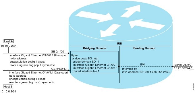
In software releases before Cisco IOS XR 4.0.1 where IRB is not supported, you would need to implement a physical cabling solution to connect the egress Layer 2 bridge domain interface to a Layer 3 routing domain interface on the same Cisco ASR 9000 Series Router. In Cisco IOS XR Release 4.0.1, IRB accomplishes the same functionality using a BVI and its supporting interface and bridge group configuration shown in Figure 1.
Figure 1 IRB Functional View and Configuration Elements
Bridge-Group Virtual Interface
This section includes the following information:
•
BVI Introduction
The BVI is a virtual interface within the router that acts like a normal routed interface. The BVI does not support bridging itself, but acts as a gateway for the corresponding bridge-domain to a routed interface within the router.
Aside from supporting a configurable MAC address, a BVI supports only Layer 3 attributes, and has the following characteristics:
•
•
•
•
Supported Features on a BVI
•
–
–
–
–
–
–
–
•
BVI MAC Address
By default, the Cisco ASR 9000 Series Router uses one MAC address for all BVI interfaces on the router. However, this means that the MAC address is not unique globally. If you want to override the default and specify a unique MAC address at the BVI, then you can configure it at the BVI interface.
BVI Interface and Line Protocol States
Like typical interface states on the router, a BVI has both an Interface and Line Protocol state.
•
–
–
Note
•
–
–
Packet Flows Using IRB
Figure 2 shows a simplified functional diagram of an IRB implementation to describe different packet flows between Host A, B, and C. In this example, Host C is on a network with a connection to the same router. In reality, another router could be between Host C and the router shown.
Figure 2 IRB Packet Flows Between Hosts
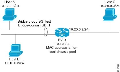
When IRB is configured on a router, the following processing happens:
•
•
•
•
•
Packet Flows When Host A Sends to Host B on the Bridge Domain
When Host A sends data to Host B in the bridge domain on the 10.10.0.0 network, no routing occurs. The hosts are on the same subnet and the packets are bridged between their segment interfaces on the router.
Packet Flows When Host A Sends to Host C From the Bridge Domain to a Routed Interface
Using host information from Figure 2, the following occurs when Host A sends data to Host C from the IRB bridging domain to the routing domain:
•
–
–
•
–
–
•
Packet Flows When Host C Sends to Host B From a Routed Interface to the Bridge Domain
Using host information from Figure 2, the following occurs when Host C sends data to Host B from the IRB routing domain to the bridging domain:
•
–
–
–
–
•
•
Supported Environments for IRB
The following environments and configuration elements are supported with IRB on the Cisco ASR 9000 Series Router:
•
•
•
•
•
•
•
•
•
•
•
•
•
•
•
•
•
•
•
How to Configure IRB
This section includes the following configuration tasks:
•
•
•
•
•
Configuring the Bridge Group Virtual Interface
To configure a BVI, complete the following steps.
Configuration Guidelines
Consider the following guidelines when configuring the BVI:
•
•
SUMMARY STEPS
1.
2.
3.
4.
5.
6.
7.
8.
9.
or
commitDETAILED STEPS
Configuring the Layer 2 AC Interfaces
To configure the Layer 2 AC interfaces for routing by a BVI, complete the following steps.
Prerequisites
The interfaces to be configured as Layer 2 ACs in the bridge domain and routed by a BVI must be located on the following types of cards supporting IRB on the Cisco ASR 9000 Series Router:
•
•
•
•
•
SUMMARY STEPS
1.
2.
3.
4.
or
encapsulation dot1ad vlan-id dot1q vlan-id
5.
6.
or
commitDETAILED STEPS
Configuring a Bridge Group and Assigning Interfaces to a Bridge Domain
To configure a bridge group and assign interfaces to a bridge domain, complete the following steps.
SUMMARY STEPS
1.
2.
3.
4.
5.
6.
or
commitDETAILED STEPS
Associating the BVI as the Routed Interface on a Bridge Domain
To associate the BVI as the routed interface on a bridge domain, complete the following steps.
SUMMARY STEPS
1.
2.
3.
4.
5.
6.
or
commitDETAILED STEPS
Displaying Information About a BVI
To display information about BVI status and packet counters, use the following commands:
Configuration Examples for IRB
This section provides the following configuration examples:
•
•
•
•
•
Basic IRB Configuration: Example
The following example shows how to perform the most basic IRB configuration:
! Configure the BVI and its IPv4 address!RP/0/RSP0/CPU0:router# configureRP/0/RSP0/CPU0:router(config)# interface bvi 1RP/0/RSP0/CPU0:router(config-if))# ipv4 address 10.10.0.4 255.255.255.0RP/0/RSP0/CPU0:router(config-if))# exit!! Configure the Layer 2 AC interface!RP/0/RSP0/CPU0:router(config)# interface GigabitEthernet 0/1/0/0 l2transportRP/0/RSP0/CPU0:router(config-if))# exit!! Configure the L2VPN bridge group and bridge domain and assign interfaces!RP/0/RSP0/CPU0:router(config)# l2vpnRP/0/RSP0/CPU0:router(config-l2vpn)# bridge group 10RP/0/RSP0/CPU0:router(config-l2vpn-bg)# bridge-domain 1RP/0/RSP0/CPU0:router(config-l2vpn-bg-bd)# interface GigabitEthernet 0/1/0/0RP/0/RSP0/CPU0:router(config-l2vpn-bg-bd-if)# exit!! Associate a BVI to the bridge domain!RP/0/RSP0/CPU0:router(config-l2vpn-bg-bd)# routed interface bvi 1RP/0/RSP0/CPU0:router(config-l2vpn-bg-bd)# commitIRB Using ACs With VLANs: Example
The following example shows how to configure IRB on a bridge domain with Layer 2 ACs using 802.1q-encapsulated VLANs:
! Configure the BVI and its IPv4 address!RP/0/RSP0/CPU0:router# configureRP/0/RSP0/CPU0:router(config)# interface bvi 1RP/0/RSP0/CPU0:router(config-if))# ipv4 address 10.10.0.4 255.255.255.0RP/0/RSP0/CPU0:router(config-if))# exit!! Configure the Layer 2 AC interfaces using dot1q encapsulation on a VLAN!RP/0/RSP0/CPU0:router(config)# interface GigabitEthernet 0/1/0/0.1 l2transportRP/0/RSP0/CPU0:router(config-if))# no ip addressRP/0/RSP0/CPU0:router(config-if))# encapsulation dot1q 1 exactRP/0/RSP0/CPU0:router(config-if))# rewrite ingress tag pop 1 symmetricRP/0/RSP0/CPU0:router(config-if))# exitRP/0/RSP0/CPU0:router(config)# interface GigabitEthernet 0/1/0/1.1 l2transportRP/0/RSP0/CPU0:router(config-if))# no ip addressRP/0/RSP0/CPU0:router(config-if))# encapsulation dot1q 1 exactRP/0/RSP0/CPU0:router(config-if))# rewrite ingress tag pop 1 symmetricRP/0/RSP0/CPU0:router(config-if))# exit!! Configure the L2VPN bridge group and bridge domain and assign interfaces!RP/0/RSP0/CPU0:router(config)# l2vpnRP/0/RSP0/CPU0:router(config-l2vpn)# bridge group 10RP/0/RSP0/CPU0:router(config-l2vpn-bg)# bridge-domain 1RP/0/RSP0/CPU0:router(config-l2vpn-bg-bd)# interface GigabitEthernet 0/1/0/0.1RP/0/RSP0/CPU0:router(config-l2vpn-bg-bd)# interface GigabitEthernet 0/1/0/1.1RP/0/RSP0/CPU0:router(config-l2vpn-bg-bd-if)# exit!! Associate a BVI to the bridge domain!RP/0/RSP0/CPU0:router(config-l2vpn-bg-bd)# routed interface bvi 1RP/0/RSP0/CPU0:router(config-l2vpn-bg-bd)# commitIPv4 Addressing on a BVI Supporting Multiple IP Networks: Example
The following example shows how to configure secondary IPv4 addresses on a BVI that supports bridge domains for the 10.10.10.0/24, 10.20.20.0/24, and 10.30.30.0/24 networks. In this example, the BVI must have an address on each of the bridge domain networks:
RP/0/RSP0/CPU0:router# configureRP/0/RSP0/CPU0:router(config)# interface bvi 1RP/0/RSP0/CPU0:router(config-if))# ipv4 address 10.10.10.4 255.255.255.0RP/0/RSP0/CPU0:router(config-if))# ipv4 address 10.20.20.4 255.255.255.0 secondaryRP/0/RSP0/CPU0:router(config-if))# ipv4 address 10.30.30.4 255.255.255.0 secondaryRP/0/RSP0/CPU0:router(config-if))# commitComprehensive IRB Configuration with BVI Bundle Interfaces and Multicast Configuration: Example
NOTE: Router prompts will be added time permitting or in future update.
The following example shows a more comprehensive router configuration with IRB and BVI multicast support:
interface Bundle-Ether25ipv4 address 10.21.0.2 255.255.255.0!interface Loopback0ipv4 address 10.5.5.5 255.255.255.255!interface GigabitEthernet0/0/0/1negotiation auto!interface GigabitEthernet0/0/0/1.1 l2transportencapsulation dot1q 1rewrite ingress tag pop 1 symmetric!interface GigabitEthernet0/0/0/1.2 l2transportencapsulation dot1q 2rewrite ingress tag pop 1 symmetric!interface GigabitEthernet0/0/0/9bundle id 25 mode active!interface GigabitEthernet0/0/0/19bundle id 25 mode active!interface GigabitEthernet0/0/0/29bundle id 25 mode active!interface GigabitEthernet0/0/0/39bundle id 25 mode activeinterface BVI1ipv4 address 10.1.1.1 255.255.255.0!interface BVI2ipv4 address 10.1.2.1 255.255.255.0router ospf 100router-id 10.5.5.5area 0interface Bundle-Ether25interface Loopback0interface BVI1interface BVI2!l2vpnbridge group irbbridge-domain irb1igmp snooping profile irb_snoopinterface GigabitEthernet0/0/0/1.1!routed interface BVI1!bridge-domain irb2igmp snooping profile irb_snoopinterface GigabitEthernet0/0/0/1.2!routed interface BVI2multicast-routingaddress-family ipv4interface all enableigmp snooping profile irb_snoopreport-suppression disable!router pimaddress-family ipv4rp-address 10.10.10.10IRB With BVI and VRRP Configuration: Example
NOTE: Router prompts will be added time permitting or in future update.
The following example shows a partial router configuration for the relevant configuration areas for IRB support of a BVI and VRRP:
l2vpnbridge group irbbridge-domain irb-edgeinterface GigabitEthernet0/0/0/8!routed interface BVI 100!!!interface GigabitEthernet0/0/0/8l2transport!interface BVI100ipv4 address 10.21.1.1 255.255.255.0!router vrrpinterface BVI 100vrrp 1 ipv4 10.21.1.100vrrp 1 priority 100!Additional References
The following sections provide references related to configuring IRB on the Cisco ASR 9000 Series Router.
Related Documents
Ethernet L2VPN
Cisco ASR 9000 Series Aggregation Services Router L2VPN and Ethernet Services Configuration Guide
Cisco ASR 9000 Series Aggregation Services Router L2VPN and Ethernet Services Command Reference
Cisco IOS XR master command reference
Cisco ASR 9000 Series Aggregation Services Router Master Command Listing, Release 4.0
Cisco IOS XR interface configuration commands
Cisco ASR 9000 Series Aggregation Services Router Interface and Hardware Component Command Reference
Cisco IOS XR multicast configuration
Cisco ASR 9000 Series Aggregation Services Router Multicast Configuration Guide
Standards
No new or modified standards are supported by this feature, and support for existing standards has not been modified by this feature.
—
MIBs
IF-MIB
To locate and download MIBs for selected platforms using
Cisco IOS XR Software, use the Cisco MIB Locator found at the following URL:
RFCs
No new or modified RFCs are supported by this feature, and support for existing RFCs has not been modified by this feature.
—
Technical Assistance
 Feedback
Contact Cisco
- Open a Support Case

- (Requires a Cisco Service Contract)