Table Of Contents
Implementing MPLS VPNs over IP Tunnels on
Cisco IOS XR Software
Contents
Prerequisites for Configuring MPLS VPNs over IP Tunnels
Restrictions for Configuring MPLS VPNs over IP Tunnels
Information About MPLS VPNs over IP Tunnels
Overview: MPLS VPNs over IP Tunnels
Advertising Tunnel Type and Tunnel Capabilities Between PE Routers—BGP
PE Routers and Address Space
Packet Validation Mechanism
Quality of Service Using the Modular QoS CLI
BGP Multipath Load Sharing for MPLS VPNs over IP Tunnels
Inter-AS and CSC Support over IP Tunnels
How to Configure MPLS VPNs over IP Tunnels
Configuring the Global VRF Definition
Configuring a Route-Policy Definition
Configuring a Static Route
Configuring an IPv4 Loopback Interface
Configuring a CFI VRF Interface
Configuring the Core Network
Configuring Inter-AS and CSC Support over IP Tunnels
Configuring the ASBRs to Exchange VPN-IPv4 Addresses for IP Tunnels
Configuring the Backbone Carrier Core for IP Tunnels
Configuring CSC-PE Routers for IP Tunnels
Verifying MPLS VPN over IP
Configuration Examples for MPLS VPNs over IP Tunnels
Configuring an L2TPv3 Tunnel: Example
Configuring the Global VRF Definition: Example
Configuring a Route-Policy Definition: Example
Configuring a Static Route: Example
Configuring an IPv4 Loopback Interface: Example
Configuring a CFI VRF Interface: Example
Additional References
Related Documents
Standards
MIBs
RFCs
Technical Assistance
Implementing MPLS VPNs over IP Tunnels on
Cisco IOS XR Software
The MPLS VPNs over IP Tunnels feature lets you deploy Layer 3 Virtual Private Network (L3VPN) services, over an IP core network, using L2TPv3 multipoint tunneling instead of MPLS. This allows L2TPv3 tunnels to be configured as multipoint tunnels to transport IP VPN services across the core IP network.
Note  This feature is available on the Cisco XR 12000 Series Router only.
Feature History for Implementing MPLS VPNs over IP Tunnels on Cisco IOS XR Software
|
Release
|
Modification
|
Release 3.5.0 |
This feature was introduced on the Cisco XR 12000 Series Router. |
Release 3.6.0 |
No modification. |
Release 3.7.0 |
No modification. |
Contents
•Prerequisites for Configuring MPLS VPNs over IP Tunnels
•Restrictions for Configuring MPLS VPNs over IP Tunnels
•Information About MPLS VPNs over IP Tunnels
•How to Configure MPLS VPNs over IP Tunnels
•Configuration Examples for MPLS VPNs over IP Tunnels
•Additional References
Prerequisites for Configuring MPLS VPNs over IP Tunnels
The following prerequisites are required to implement MPLS VPNs over IP Tunnels:
•You must be in a user group associated with a task group that includes the proper task IDs for
–BGP commands
–MPLS commands (generally)
–MPLS Layer 3 VPN commands
For detailed information about user groups and task IDs, see the Configuring AAA Services on Cisco IOS XR Software module of Cisco IOS XR System Security Configuration Guide.
Restrictions for Configuring MPLS VPNs over IP Tunnels
The following restrictions apply when you configure MPLS VPNs over IP tunnels:
•MPLS forwarding cannot be enabled on a provider edge (PE) router.
Information About MPLS VPNs over IP Tunnels
To implement MPLS VPNs over IP Tunnels, you must understand the following concepts:
•Overview: MPLS VPNs over IP Tunnels
•Advertising Tunnel Type and Tunnel Capabilities Between PE Routers—BGP
•PE Routers and Address Space
•Packet Validation Mechanism
•Quality of Service Using the Modular QoS CLI
•BGP Multipath Load Sharing for MPLS VPNs over IP Tunnels
•Inter-AS and CSC Support over IP Tunnels
Overview: MPLS VPNs over IP Tunnels
Traditionally, VPN services are deployed over IP core networks using MPLS, or L2TPv3 tunnels using point-to-point links. However, an L2TPv3 multipoint tunnel network allows L3VPN services to be carried through the core without the configuration of MPLS.
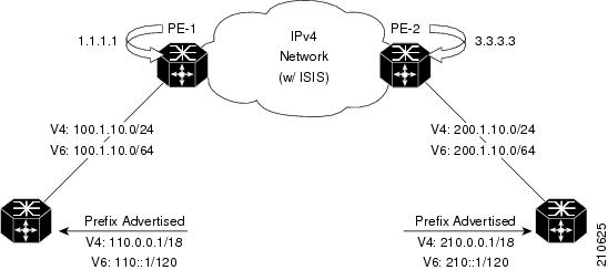
L2TPv3 multipoint tunneling supports multiple tunnel endpoints, which creates a full-mesh topology that requires only one tunnel to be configured on each PE router. This permits VPN traffic to be carried from enterprise networks across cooperating service provider core networks to remote sites.
Figure 25 illustrates the topology used for the configuration steps.
Figure 25 Basic MPLS VPN over IP Topology
Advertising Tunnel Type and Tunnel Capabilities Between PE Routers—BGP
Border Gateway Protocol (BGP) is used to advertise the tunnel endpoints and the subaddress family identifier (SAFI) specific attributes (which contains the tunnel type, and tunnel capabilities). This feature introduces the tunnel SAFI and the BGP SAFI-Specific Attribute (SSA) attribute.
These attributes allow BGP to distribute tunnel encapsulation information between PE routers. VPNv4 traffic is routed through these tunnels. The next hop, advertised in BGP VPNv4 updates, determines which tunnel to use for routing tunnel traffic.
SAFI
The tunnel SAFI defines the tunnel endpoint and carries the endpoint IPv4 address and next hop. It is identified by the SAFI number 64.
BGP SSA
The BGP SSA carries the BGP preference and BGP flags. It also carries the tunnel cookie, tunnel cookie length, and session ID. It is identified by attribute number 19.
PE Routers and Address Space
One multipoint L2TPv3 tunnel must be configured on each PE router. To create the VPN, you must configure a unique Virtual Routing and Forwarding (VRF) instance. The tunnel that transports the VPN traffic across the core network resides in its own address space. A special purpose VRF called a Resolve in VRF (RiV) is created to manage the tunnel address space. You also configure the address space under the RiV that is associated with the tunnel and a static route in the RiV to route outgoing traffic through the tunnel.
Packet Validation Mechanism
The MPLS VPNs over IP Tunnels feature provides a simple mechanism to validate received packets from appropriate peers. The multipoint L2TPv3 tunnel header is automatically configured with a 64-bit cookie and L2TPv3 session ID. This packet validation mechanism protects the VPN from illegitimate traffic sources. The cookie and session ID are not user-configurable, but they are visible in the packet as it is routed between the two tunnel endpoints. Note that this packet validation mechanism does not protect the VPN from hackers who are able to monitor legitimate traffic between PE routers.
Quality of Service Using the Modular QoS CLI
To configure the bandwidth on the encapsulation and decapsulation interfaces, use the modular QoS CLI (MQC).
Note This task is optional.
Use the MQC to configure the IP precedence or Differentiated Services Code Point (DSCP) value set in the IP carrier header during packet encapsulation. To set these values, enter a standalone set command or a police command using the keyword tunnel. In the input policy on the encapsulation interface, you can set the precedence or DSCP value in the IP payload header by using MQC commands without the keyword tunnel.
Note You must attach a QoS policy to the physical interface—not to the tunnel interface.
If Modified Deficit Round Robin (MDRR)/Weighted Random Early Detection (WRED) is configured for the encapsulation interface in the input direction, the final value of the precedence or DSCP field in the IP carrier header is used to determine the precedence class for which the MDRR/WRED policy is applied. On the decapsulation interface in the input direction, you can configure a QoS policy based on the precedence or DSCP value in the IP carrier header of the received packet. In this case, an MQC policy with a class to match on precedence or DSCP value will match the precedence or DSCP value in the received IP carrier header. Similarly, the precedence class for which the MDRR/WRED policy is applied on the decapsulation input direction is also determined by precedence or DSCP value in the IP carrier header.
BGP Multipath Load Sharing for MPLS VPNs over IP Tunnels
BGP Multipath Load Sharing for EBGP and IBGP lets you configure multipath load balancing with both external BGP and internal BGP paths in BGP networks that are configured to use MPLS VPNs. (When faced with multiple routes to the same destination, BGP chooses the best route for routing traffic toward the destination so that no individual router is overburdened.)
BGP Multipath Load Sharing is useful for multihomed autonomous systems and PE routers that import both EBGP and IBGP paths from multihomed and stub networks.
Inter-AS and CSC Support over IP Tunnels
The L3VPN Inter-AS feature provides a method of interconnecting VPNs between different VPN service providers. Inter-AS supports connecting different VPN service providers to provide native IP L3VPN services. For more information about Inter-AS, see Implementing MPLS Layer 3 VPNs on Cisco IOS XR Software.
Carrier Supporting Carrier (CSC) is implemented in circumstances in which one service provider needs to use the transport services provided by another service provider. The service provider that provides the transport is called the backbone carrier. The service provider, which uses the services provided by the backbone carrier, is called a customer carrier. Backbone carriers with CSC, bridge two or more customer carrier sites through an MPLS VPN/MPLS VPN over IP tunnels backbone. For more information about CSC, see Implementing MPLS VPNs over IP Tunnels on Cisco IOS XR Software.
How to Configure MPLS VPNs over IP Tunnels
The following procedures are required to configure MPLS VPN over IP:
•Configuring the Global VRF Definition (required)
•Configuring a Route-Policy Definition (required)
•Configuring a Static Route (required)
•Configuring an IPv4 Loopback Interface (required)
•Configuring a CFI VRF Interface (required)
•Configuring the Core Network (required)
•Configuring Inter-AS and CSC Support over IP Tunnels
•Verifying MPLS VPN over IP (optional)
Note All procedures occur on the local PE (PE1). Corresponding procedures must be configured on the remote PE (PE2).
Configuring the Global VRF Definition
Perform this task to configure the global VRF definition.
SUMMARY STEPS
1. configure
2. vrf vrf-name
3. address-family ipv4 unicast
4. import route-target [0-65535.0-65535:0-65535 | as-number:nn | ip-address:nn]
5. export route-target [0-65535.0-65535:0-65535 | as-number:nn | ip-address:nn]
6. exit
7. address-family ipv6 unicast
8. import route-target [0-65535.0-65535:0-65535 | as-number:nn | ip-address:nn]
9. export route-target [0-65535.0-65535:0-65535 | as-number:nn | ip-address:nn]
10. end
or
commit
DETAILED STEPS
| |
Command or Action
|
Purpose
|
Step 1 |
configure
Example:
RP/0/0/CPU0:router# configure |
Enters global configuration mode. |
Step 2 |
vrf vrf-name
Example:
RP/0/0/CPU0:router(config)# vrf vrf-name |
Specifies a name assigned to a VRF. |
Step 3 |
address-family ipv4 unicast
Example:
RP/0/0/CPU0:router(config-vrf)# address-family ipv4 unicast |
Specifies an IPv4 address-family address. |
Step 4 |
import route-target [0-65535.0-65535:0-65535 | as-number:nn | ip-address:nn]
Example:
RP/0/0/CPU0:router(config-vrf-af)# import route-target 500:99 |
Configures a VPN routing and forwarding (VRF) import route-target extended community. |
Step 5 |
export route-target [0-65535.0-65535:0-65535 | as-number:nn | ip-address:nn]
Example:
RP/0/0/CPU0:router(config-vrf-af)# export route-target 700:44 |
Configures a VPN routing and forwarding (VRF) export route-target extended community. |
Step 6 |
exit
Example:
RP/0/0/CPU0:router(config-vrf-af)# exit |
Exits interface configuration mode. |
Step 7 |
address-family ipv6 unicast
Example:
RP/0/0/CPU0:router(config-vrf)# address-family ipv6 unicast |
Specifies an IPv6 address-family address. |
Step 8 |
import route-target [0-65535.0-65535:0-65535 | as-number:nn | ip-address:nn]
Example:
RP/0/0/CPU0:router(config-vrf-af)# import route-target 500:99 |
Configures a VPN routing and forwarding (VRF) import route-target extended community. |
Step 9 |
export route-target [0-65535.0-65535:0-65535 | as-number:nn | ip-address:nn]
Example:
RP/0/0/CPU0:router(config-vrf-af)# import route-target 700:88 |
Configures a VPN routing and forwarding (VRF) export route-target extended community. |
Step 10 |
end or commit
Example:
RP/0/0/CPU0:router(config-vrf-af)# end or RP/0/0/CPU0:router(config-vrf-af)# commit |
Saves configuration changes. •When you issue the end command, the system prompts you to commit changes:
Uncommitted changes found, commit them before
exiting(yes/no/cancel)?
[cancel]:
–Entering yes saves configuration changes to the running configuration file, exits the configuration session, and returns the router to EXEC mode. –Entering no exits the configuration session and returns the router to EXEC mode without committing the configuration changes. –Entering cancel leaves the router in the current configuration session without exiting or committing the configuration changes. •Use the commit command to save the configuration changes to the running configuration file and remain within the configuration session. |
Configuring a Route-Policy Definition
Perform this task to configure a route-policy definition for CE-PE EBGP.
SUMMARY STEPS
1. configure
2. route-policy name pass
3. end policy
DETAILED STEPS
| |
Command or Action
|
Purpose
|
Step 1 |
configure
Example:
RP/0/0/CPU0:router# configure |
Enters global configuration mode. |
Step 2 |
route-policy name pass
Example:
RP/0/0/CPU0:router(config)# route-policy ottawa_admin pass |
Defines and passes a route policy. |
Step 3 |
end policy
Example:
RP/0/0/CPU0:router(config-rpl)# end policy |
End of route-policy definition. |
Configuring a Static Route
Perform this task to add more than 4K static routes (Global/VRF).
SUMMARY STEPS
1. configure
2. router static
3. maximum path ipv4 1-140000
4. maximum path ipv6 1-140000
5. end
or
commit
DETAILED STEPS
| |
Command or Action
|
Purpose
|
Step 1 |
configure
Example:
RP/0/0/CPU0:router# configure |
Enters global configuration mode. |
Step 2 |
router static
Example:
RP/0/0/CPU0:router(config)# router static |
Enters static route configuration subcommands. |
Step 3 |
maximum path ipv4 1-140000
Example:
RP/0/0/CPU0:router (config-static)# maximum path ipv4 1-140000 |
Enters the maximum number of static ipv4 paths that can be configured. |
Step 4 |
maximum path ipv6 1-140000
Example:
RP/0/0/CPU0:router(config-static)# maximum path ipv6 1-140000 |
Enters the maximum number of static ipv6 paths that can be configured. |
Step 5 |
end or commit
Example:
RP/0/0/CPU0:router(config-static)# end or RP/0/0/CPU0:router(config-static)# commit |
Saves configuration changes. •When you issue the end command, the system prompts you to commit changes:
Uncommitted changes found, commit them before
exiting(yes/no/cancel)?
[cancel]:
–Entering yes saves configuration changes to the running configuration file, exits the configuration session, and returns the router to EXEC mode. –Entering no exits the configuration session and returns the router to EXEC mode without committing the configuration changes. –Entering cancel leaves the router in the current configuration session without exiting or committing the configuration changes. •Use the commit command to save the configuration changes to the running configuration file and remain within the configuration session. |
Configuring an IPv4 Loopback Interface
The following task describes how to configure an IPv4 Loopback interface.
SUMMARY STEPS
1. configure
2. interface type interface-id
3. ipv4 address ipv4-address
4. end
or
commit
DETAILED STEPS
| |
Command or Action
|
Purpose
|
Step 1 |
configure
Example:
RP/0/0/CPU0:router# configure |
Enters global configuration mode. |
Step 2 |
interface type interface-id
Example:
RP/0/0/CPU0:router(config)# interface Loopback0 |
Enters interface configuration mode and enables a Loopback interface. |
Step 3 |
ipv4 address ipv4-address
Example:
RP/0/0/CPU0:router(config-if)# ipv4 address 1.1.1.1 255.255.255.255 |
Enters an IPv4 address and mask for the associated IP subnet. The network mask can be specified in either of two ways: •The network mask can be a four-part dotted decimal address. For example, 255.0.0.0 indicates that each bit equal to 1 means that the corresponding address bit belongs to the network address. •The network mask can be indicated as a slash (/) and number. For example, /8 indicates that the first 8 bits of the mask are ones, and the corresponding bits of the address are the network address. |
Step 4 |
end or commit
Example:
RP/0/0/CPU0:router(config-if)# end or RP/0/0/CPU0:router(config-if)# commit |
Saves configuration changes. •When you issue the end command, the system prompts you to commit changes:
Uncommitted changes found, commit them before
exiting(yes/no/cancel)?
[cancel]:
–Entering yes saves configuration changes to the running configuration file, exits the configuration session, and returns the router to EXEC mode. –Entering no exits the configuration session and returns the router to EXEC mode without committing the configuration changes. –Entering cancel leaves the router in the current configuration session without exiting or committing the configuration changes. •Use the commit command to save the configuration changes to the running configuration file and remain within the configuration session. |
Configuring a CFI VRF Interface
Perform this task to associate a VPN routing and forwarding (VRF) instance with an interface or a subinterface on the PE routers.
SUMMARY STEPS
1. configure
2. interface type interface-id
3. vrf vrf-name
4. ipv4 address ipv4-address
5. ipv6 address ipv6-address
6. dot1q vlan vlan-id
7. end
or
commit
DETAILED STEPS
| |
Command or Action
|
Purpose
|
Step 1 |
configure
Example:
RP/0/0/CPU0:router# configure |
Enters global configuration mode. |
Step 2 |
interface type interface-id
Example:
RP/0/0/CPU0:router(config)# interface GigabitEthernet0/0/0/1.1 |
Enters interface configuration mode and enables a GigabitEthernet interface. |
Step 3 |
vrf vrf-name
Example:
RP/0/0/CPU0:router(config-if)# vrf v1 |
Specifies a VRF name. |
Step 4 |
ipv4 address ipv4-address
Example:
RP/0/0/CPU0:router(config-if)# ipv4 address 100.1.10.2 255.255.255.0 |
Enters an IPv4 address and mask for the associated IP subnet. The network mask can be specified in either of two ways: •The network mask can be a four-part dotted decimal address. For example, 255.0.0.0 indicates that each bit equal to 1 means that the corresponding address bit belongs to the network address. •The network mask can be indicated as a slash (/) and number. For example, /8 indicates that the first 8 bits of the mask are ones, and the corresponding bits of the address are network address. |
Step 5 |
ipv6 address ipv6-address
Example:
RP/0/0/CPU0:router(config-if)# ipv6 100::1:10:2/64 |
Enters an IPv6 address. This argument must be in the form documented in
RFC 2373, where the address is specified in hexadecimal using 16-bit values between colons, as follows: •IPv6 name or address: Hostname or X:X::X%zone •IPv6 prefix: X:X::X%zone/<0-128> |
Step 6 |
dot1q native vlan vlan-id
Example:
RP/0/0/CPU0:router(config-if)# dot1q native vlan 665 |
Enters the trunk interface ID. Range is from 1 to 4094 inclusive (0 and 4095 are reserved). |
Step 7 |
end or commit
Example:
RP/0/0/CPU0:router(config-if)# end or RP/0/0/CPU0:router(config-if)# commit |
Saves configuration changes. •When you issue the end command, the system prompts you to commit changes:
Uncommitted changes found, commit them before
exiting(yes/no/cancel)?
[cancel]:
–Entering yes saves configuration changes to the running configuration file, exits the configuration session, and returns the router to EXEC mode. –Entering no exits the configuration session and returns the router to EXEC mode without committing the configuration changes. –Entering cancel leaves the router in the current configuration session without exiting or committing the configuration changes. •Use the commit command to save the configuration changes to the running configuration file and remain within the configuration session. |
Configuring the Core Network
To configure the core network, refer to the procedures documented in Implementing MPLS Layer 3 VPNs on Cisco IOS XR Software.
The tasks are presented as follows:
•Assessing the needs of MPLS VPN customers
•Configuring routing protocols in the core
•Configuring MPLS in the core
•Enabling FIB in the core
•Configuring BGP on the PE routers and route reflectors
Configuring Inter-AS and CSC Support over IP Tunnels
These tasks describe how to configure Inter-AS and CSC support over IP tunnels:
•Configuring the ASBRs to Exchange VPN-IPv4 Addresses for IP Tunnels (required)
•Configuring the Backbone Carrier Core for IP Tunnels
•Configuring CSC-PE Routers for IP Tunnels
Configuring the ASBRs to Exchange VPN-IPv4 Addresses for IP Tunnels
Perform this task to configure an external Border Gateway Protocol (eBGP) autonomous system boundary router (ASBR) to exchange VPN-IPv4 routes with another autonomous system for IP tunnels
Note This procedure is supported on the Cisco XR 12000 Series Router.
SUMMARY STEPS
1. configure
2. router bgp autonomous-system-number
3. address-family {ipv4 tunnel}
4. address-family {vpnv4 unicast}
5. neighbor ip-address
6. remote-as autonomous-system-number
7. address-family {vpnv4 unicast}
8. route-policy route-policy-name {in}
9. route-policy route-policy-name {out}
10. neighbor ip-address
11. remote-as autonomous-system-number
12. update-source interface-type interface-number
13. address-family {ipv4 tunnel}
14. address-family {vpnv4 unicast}
15. end
or
commit
DETAILED STEPS
| |
Command or Action
|
Purpose
|
Step 1 |
configure
Example:
RP/0/0/CPU0:router# configure |
Enters global configuration mode. |
Step 2 |
router bgp autonomous-system-number
Example:
RP/0/0/CPU0:router(config)# router bgp 120 RP/0/0/CPU0:router(config-bgp)# |
Enters Border Gateway Protocol (BGP) configuration mode allowing you to configure the BGP routing process. |
Step 3 |
address-family {ipv4 tunnel}
Example:
RP/0/0/CPU0:router(config-bgp)# address-family ipv4 tunnel RP/0/0/CPU0:router(config-bgp-af)# |
Configures IPv4 tunnel address family. |
Step 4 |
address-family {vpnv4 unicast}
Example:
RP/0/0/CPU0:router(cconfig-bgp-af)# address-family vpnv4 unicast |
Configures VPNv4 address family. |
Step 5 |
neighbor ip-address
Example:
RP/0/0/CPU0:router(config-bgp-af)# neighbor 172.168.40.24 RP/0/0/CPU0:router(config-bgp-nbr)# |
Places the router in neighbor configuration mode for BGP routing and configures the neighbor IP address 172.168.40.24 as an ASBR eBGP peer. |
Step 6 |
remote-as autonomous-system-number
Example:
RP/0/0/CPU0:router(config-bgp-nbr)# remote-as 2002 |
Creates a neighbor and assigns it a remote autonomous system number. |
Step 7 |
address-family {vpnv4 unicast}
Example:
RP/0/0/CPU0:router(config-bgp-nbr)# address-family vpnv4 unicast RP/0/0/CPU0:router(config-bgp-nbr-af)# |
Configures VPNv4 address family. |
Step 8 |
route-policy route-policy-name {in}
Example:
RP/0/0/CPU0:router(config-bgp-nbr-af)# route-policy pass-all in |
Applies a routing policy to updates that are received from a BGP neighbor. •Use the route-policy-name argument to define the name of the of route policy. The example shows that the route policy name is defined as pass-all. •Use the in keyword to define the policy for inbound routes. |
Step 9 |
route-policy route-policy-name {out}
Example:
RP/0/0/CPU0:router(config-bgp-nbr-af)# route-policy pass-all out |
Applies a routing policy to updates that are sent from a BGP neighbor. •Use the route-policy-name argument to define the name of the of route policy. The example shows that the route policy name is defined as pass-all. •Use the out keyword to define the policy for outbound routes. |
Step 10 |
neighbor ip-address
Example:
RP/0/0/CPU0:router(config-bgp-nbr-af)# neighbor 175.40.25.2 RP/0/0/CPU0:router(config-bgp-nbr)# |
Places the router in neighbor configuration mode for BGP routing and configures the neighbor IP address 175.40.25.2 as an VPNv4 iBGP peer. |
Step 11 |
remote-as autonomous-system-number
Example:
RP/0/0/CPU0:router(config-bgp-nbr)# remote-as 2002 |
Creates a neighbor and assigns it a remote autonomous system number. |
Step 12 |
update-source interface-type interface-number
Example:
RP/0/0/CPU0:router(config-bgp-nbr)# update-source loopback0 |
Allows BGP sessions to use the primary IP address from a particular interface as the local address. |
Step 13 |
address-family {ipv4 tunnel}
Example:
RP/0/0/CPU0:router(config-bgp-nbr)# address-family ipv4 tunnel RP/0/0/CPU0:router(config-bgp-nbr-af)# |
Configures IPv4 tunnel address family. |
Step 14 |
address-family {vpnv4 unicast}
Example:
RP/0/0/CPU0:router(config-bgp-nbr-af)# address-family vpnv4 unicast |
Configures VPNv4 address family. |
Step 15 |
end or commit
Example:
RP/0/0/CPU0:router(config-bgp-nbr-af)# end or RP/0/0/CPU0:router(config-bgp-nbr-af)# commit |
Saves configuration changes. •When you issue the end command, the system prompts you to commit changes:
Uncommitted changes found, commit them before
exiting(yes/no/cancel)?
[cancel]:
–Entering yes saves configuration changes to the running configuration file, exits the configuration session, and returns the router to EXEC mode. –Entering no exits the configuration session and returns the router to EXEC mode without committing the configuration changes. –Entering cancel leaves the router in the current configuration session without exiting or committing the configuration changes. •Use the commit command to save the configuration changes to the running configuration file and remain within the configuration session. |
Configuring the Backbone Carrier Core for IP Tunnels
Configuring the backbone carrier core requires setting up connectivity and routing functions for the CSC core and the CSC-PE routers. To do so, you must complete the following high-level tasks:
•Verify IP connectivity in the CSC core.
•Configure IP tunnels in the core.
•Configure VRFs for CSC-PE routers.
•Configure multiprotocol BGP for VPN connectivity in the backbone carrier.
Configuring CSC-PE Routers for IP Tunnels
Perform this task to configure a CSC-PE for IP tunnels.
For information on how to configure CSC-CE routers, see the Implementing MPLS Layer 3 VPNs on Cisco IOS XR Software module.
SUMMARY STEPS
1. configure
2. router bgp as-number
3. address-family {vpnv4 unicast}
4. address-family {ipv4 tunnel}
5. neighbor A.B.C.D
6. remote-as as-number
7. update-source interface-type interface-number
8. address-family {vpnv4 unicast}
9. address-family {ipv4 tunnel}
10. vrf vrf-name
11. rd {as-number:nn | ip-address:nn | auto}
12. address-family {ipv4 unicast}
13. allocate-label all
14. neighbor A.B.C.D
15. remote-as as-number
16. address-family {ipv4 labeled-unicast}
17. route-policy route-policy-name in
18. route-policy route-policy-name out
19. end
or
commit
DETAILED STEPS
| |
Command or Action
|
Purpose
|
Step 1 |
configure
Example:
RP/0/0/CPU0:router# configure |
Enters global configuration mode. |
Step 2 |
router bgp as-number
Example:
RP/0/0/CPU0:router(config)# router bgp 2
RP/0/0/CPU0:router(config-bgp)#
|
Configures a BGP routing process and enters router configuration mode. •Range for 2-byte numbers is 1 to 65535. Range for 4-byte numbers is 1.0 to 65535.65535. |
Step 3 |
address-family {vpnv4 unicast}
Example:
RP/0/0/CPU0:router(config-bgp)# address-family vpnv4 unicast RP/0/0/CPU0:router(config-bgp-af)# |
Configures VPNv4 address family. |
Step 4 |
address-family {ipv4 tunnel}
Example:
RP/0/0/CPU0:router(config-bgp-af)# address-family ipv4 tunnel |
Configures IPv4 tunnel address family. |
Step 5 |
neighbor A.B.C.D
Example:
RP/0/0/CPU0:router(config-bgp-af)# neighbor 10.10.10.0 RP/0/0/CPU0:router(config-bgp-nbr)# |
Configures the IP address for the BGP neighbor. |
Step 6 |
remote-as as-number
Example:
RP/0/0/CPU0:router(config-bgp-nbr)# remote-as 888 |
Configures the AS number for the BGP neighbor. |
Step 7 |
update-source interface-type interface-number
Example:
RP/0/0/CPU0:router(config-bgp-nbr)# update-source loopback0 |
Allows BGP sessions to use the primary IP address from a particular interface as the local address. |
Step 8 |
address-family {vpnv4 unicast}
Example:
RP/0/0/CPU0:router(config-bgp-nbr)# address-family vpnv4 unicast RP/0/0/CPU0:router(config-bgp-nbr-af)# |
Configures VPNv4 unicast address family. |
Step 9 |
address-family {ipv4 tunnel}
Example:
RP/0/0/CPU0:router(config-bgp-nbr-af)# address-family ipv4 tunnel |
Configures IPv4 tunnel address family. |
Step 10 |
vrf vrf-name
Example:
RP/0/0/CPU0:router(config-bgp-nbr-af)# vrf 9999 RP/0/0/CPU0:router(config-bgp-vrf)# |
Configures a VRF instance. |
Step 11 |
rd {as-number:nn | ip-address:nn | auto}
Example:
RP/0/0/CPU0:router(config-bgp-vrf)# rd auto |
Configures a route distinguisher. Note Use the auto keyword to automatically assign a unique route distinguisher. |
Step 12 |
address-family {ipv4 unicast}
Example:
RP/0/0/CPU0:router(config-bgp-vrf)# address-family ipv4 unicast RP/0/0/CPU0:router(config-bgp-vrf-af)# |
Configures IPv4 unicast address family. |
Step 13 |
allocate-label all
Example:
RP/0/0/CPU0:router(config-bgp-vrf-af)# allocate-label all |
Allocate labels for all local prefixes and prefixes received with labels. |
Step 14 |
neighbor A.B.C.D
Example:
RP/0/0/CPU0:router(config-bgp-vrf-af)# neighbor 10.10.10.0 RP/0/0/CPU0:router(config-bgp-vrf-nbr)# |
Configures the IP address for the BGP neighbor. |
Step 15 |
remote-as as-number
Example:
RP/0/0/CPU0:router(config-bgp-vrf-nbr)# remote-as 888 |
Enables the exchange of information with a neighboring BGP router. |
Step 16 |
address-family {ipv4 labeled-unicast}
Example:
RP/0/0/CPU0:router(config-bgp-vrf-nbr)# address-family ipv4 labeled-unicast RP/0/0/CPU0:router(config-bgp-vrf-nbr-af)# |
Configures IPv4 labeled-unicast address family. |
Step 17 |
route-policy route-policy-name in
Example:
RP/0/0/CPU0:router(config-bgp-vrf-nbr-af)# route-policy pass-all in |
Applies the pass-all policy to all inbound routes. |
Step 18 |
route-policy route-policy-name out
Example:
RP/0/0/CPU0:router(config-bgp-vrf-nbr-af)# route-policy pass-all out |
Applies the pass-all policy to all outbound routes. |
Step 19 |
end or commit
Example:
RP/0/0/CPU0:router(config-bgp-vrf-nbr-af)# end or RP/0/0/CPU0:router(config-bgp-vrf-nbr-af)# commit |
Saves configuration changes. •When you issue the end command, the system prompts you to commit changes:
Uncommitted changes found, commit them before
exiting(yes/no/cancel)?
[cancel]:
–Entering yes saves configuration changes to the running configuration file, exits the configuration session, and returns the router to EXEC mode. –Entering no exits the configuration session and returns the router to EXEC mode without committing the configuration changes. –Entering cancel leaves the router in the current configuration session without exiting or committing the configuration changes. •Use the commit command to save the configuration changes to the running configuration file and remain within the configuration session. |
Verifying MPLS VPN over IP
To verify the configuration of end-end (PE-PE) MPLS VPN over IP provisioning, use the following show commands:
•show cef recursive-nexthop
•show bgp ipv4 tunnel
•show bgp vpnv4 unicast summary
•show bgp vrf v1 ipv4 unicast summary
•show bgp vrf v1 ipv4 unicast prefix
•show cef vrf v1 ipv4 prefix
•show cef ipv6 recursive-nexthop
•show bgp vpnv6 unicast summary
•show bgp vrf v1 ipv6 unicast summary
•show bgp vrf v1 ipv6 unicast prefix
•show cef vrf v1 ipv6 prefix
Configuration Examples for MPLS VPNs over IP Tunnels
This section provides the following examples:
•Configuring an L2TPv3 Tunnel: Example
•Configuring the Global VRF Definition: Example
•Configuring a Route-Policy Definition: Example
•Configuring a Static Route: Example
•Configuring an IPv4 Loopback Interface: Example
•Configuring a CFI VRF Interface: Example
Configuring an L2TPv3 Tunnel: Example
The following example shows how to configure an L2TPv3 tunnel:
tunnel-template t1
encapsulation l2tp
!
source Loopback0
!
Configuring the Global VRF Definition: Example
The following example shows how to configure an L2TPv3 tunnel:
address-family ipv4 unicast
address-family ipv6 unicast
Configuring a Route-Policy Definition: Example
The following example shows how to configure a route-policy definition:
Configuring a Static Route: Example
The following example shows how to configure a static route:
maximum path ipv4 <1-140000>
maximum path ipv6 <1-140000>
Configuring an IPv4 Loopback Interface: Example
The following example shows how to configure an IPv4 Loopback Interface:
configure
interface Loopback0
ipv4 address 1.1.1.1 255.255.255.255
!
Configuring a CFI VRF Interface: Example
The following example shows how to configure an L2TPv3 tunnel:
interface GigabitEthernet0/0/0/1.1
ipv4 address 100.1.10.2 255.255.255.0
ipv6 address 100::1:10:2/64
Additional References
For additional information related to this feature, refer to the following references:
Related Documents
|
Related Topic
|
Document Title
|
Cisco IOS XR L2VPN command reference document |
MPLS Virtual Private Network Commands on Cisco IOS XR Software |
Layer 2 Tunnel Protocol Version 3 |
Layer 2 Tunnel Protocol Version 3 on Cisco IOS XR Software |
Routing (BGP, EIGRP, OSPF, and RIP) commands: complete command syntax, command modes, command history, defaults, usage guidelines, and examples |
Cisco IOS XR Routing Command Reference |
Routing (BGP, EIGRP, OSPF, and RIP) configuration |
Cisco IOS XR Routing Configuration Guide |
MPLS LDP configuration: configuration concepts, task, and examples |
Implementing MPLS Label Distribution Protocol on Cisco IOS XR Software |
MPLS Traffic Engineering Resource Reservation Protocol configuration: configuration concepts, task, and examples |
Implementing RSVP for MPLS-TE and MPLS O-UNI on Cisco IOS XR Software |
Cisco CRS-1 router getting started material |
Cisco IOS XR Getting Started Guide |
Information about user groups and task IDs |
Configuring AAA Services on Cisco IOS XR Software module of the Cisco IOS XR System Security Configuration Guide |
Standards
|
Standards
|
Title
|
No new or modified standards are supported by this feature, and support for existing standards has not been modified by this feature. |
— |
MIBs
RFCs
|
RFCs
|
Title
|
RFC 3931 |
Layer Two Tunneling Protocol - Version 3 (L2TPv3) |
RFC 2547 |
BGP/MPLS VPNs |
Technical Assistance
|
Description
|
Link
|
The Cisco Technical Support website contains thousands of pages of searchable technical content, including links to products, technologies, solutions, technical tips, and tools. Registered Cisco.com users can log in from this page to access even more content. |
http://www.cisco.com/techsupport |

 Feedback