Cisco UPOE+: The Catalyst for Expanded IT-OT Convergence White Paper
Available Languages
Bias-Free Language
The documentation set for this product strives to use bias-free language. For the purposes of this documentation set, bias-free is defined as language that does not imply discrimination based on age, disability, gender, racial identity, ethnic identity, sexual orientation, socioeconomic status, and intersectionality. Exceptions may be present in the documentation due to language that is hardcoded in the user interfaces of the product software, language used based on RFP documentation, or language that is used by a referenced third-party product. Learn more about how Cisco is using Inclusive Language.
Power over Ethernet (PoE) allows Power Sourcing Equipment (PSE) or a switch to provide power and data collectively to Powered Devices (PDs) over standard Ethernet cables. In doing so, it replaces power cables with Ethernet cables, powering newer smart devices with specific power needs and also making power easily accessible to hard-to- reach remote devices such as outdoor cameras, access points, sensors, detectors, security devices, displays, digital signage, and many other PoE-capable devices. PoE standards have significantly evolved in the past few years as more PDs have been added to the network. Earlier industry standards such as IEEE 802.3af provided maximum PoE power of 15 watts, and IEEE 802.3at provided up to 30 watts of PoE, but as the demand continued to increase, Cisco in 2011 came up with an innovative approach to provide up to 60 watts with Cisco UPOE® (Universal Power over Ethernet) over standard Category 5e or above cables. In 2018, a new IEEE standard, 802.3bt, was ratified, which increased PoE capability to 90 watts. This new standard led to the introduction of new PSE that supports not just new capabilities but also compatibility with previous standards. Cisco introduced its 90-watt-capable line card on the Cisco® Catalyst® 9400 Series Switches and a 90-watt-capable switch in the Cisco Catalyst 9300 Series that are in complete compliance with the IEEE 802.3bt standard and also support Cisco UPOE.
Cisco UPOE+ combines the new IEEE 802.3bt standard and Cisco UPOE, which means Cisco UPOE+ switches are in complete compliance with the 802.3bt standard and also support all previous standards, such as 802.3af and IEE 802.3at, as well as Cisco UPOE.
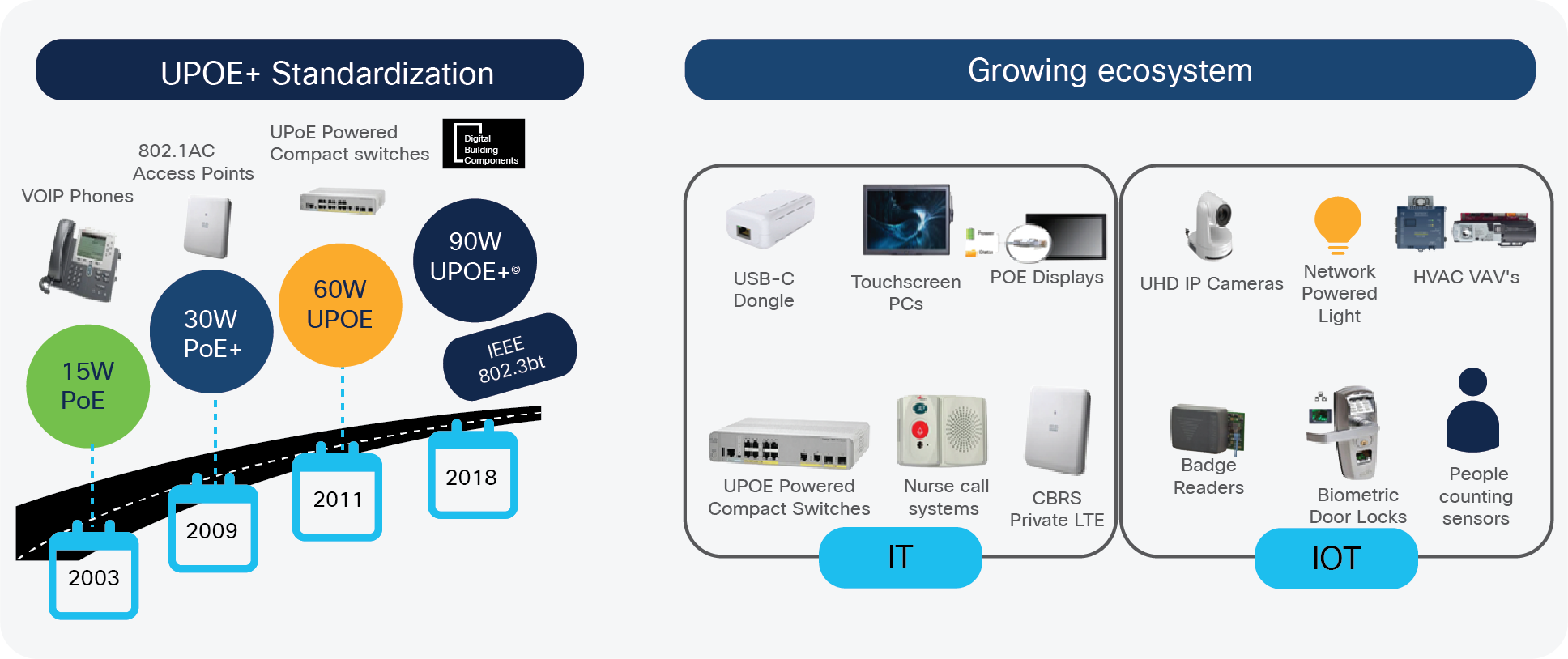
The evolution of the PoE and Cisco UPOE standards
Traditionally, IT and OT had different and specific roles in the system network, but lately they have been in synergy and are increasingly merging. Additionally, numerous endpoints are now entering the network, such as USB-C dongles, digital signage, motorized shades, intelligent sensors, touch-screen PCs, badging systems, emergency alert systems, and high-definition security cameras, and the list is ever-growing. This paper provides information about the benefits of the new 802.3bt standard, its practical use, and its backward compatibility with previous standards. It will also demystify some of the myths linked with the 802.3bt standard.
Use case 1: USB-C power
At 90 watts, 802.3bt PoE brings the ability to charge laptops plus provide high-speed data via standard Category 5e or better cables. It uses a USB-C dongle that connects to an RJ-45 wall outlet, with the other end connecting to the USB-C connector on the laptop, reducing extra cabling costs and providing the flexibility of not carrying a charger. Also, there will be no need for high-voltage power lines, and instead Ethernet cable will reduce the safety concerns of using a high-voltage connection from a wall jack. This will enable IT and operational teams to rapidly set up workspaces that provide network connectivity and USB-C PDs at events, in conference rooms and meeting rooms, and at desks for mobile workers.
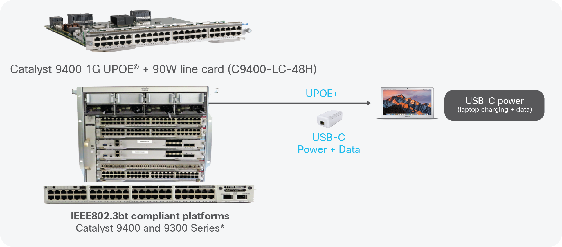
USB-C use case
Use case 2: Pass-through PoE
Pass-through PoE devices, such as compact switches, can be powered up via PoE and additionally can distribute power among their PoE ports. With Cisco UPOE+, these devices are capable of passing more power to the endpoints, which greatly simplifies the overall cabling and is ideal for space-constrained areas and wiring closets. Today Cisco provides pass-through PoE+ capable switches as part of the Cisco Digital Building solution and compact switching portfolio.
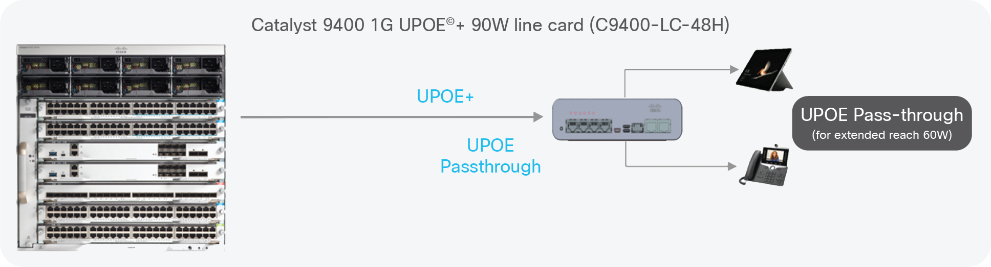
Pass-through PoE use case
Use case 3: Daisy-chaining
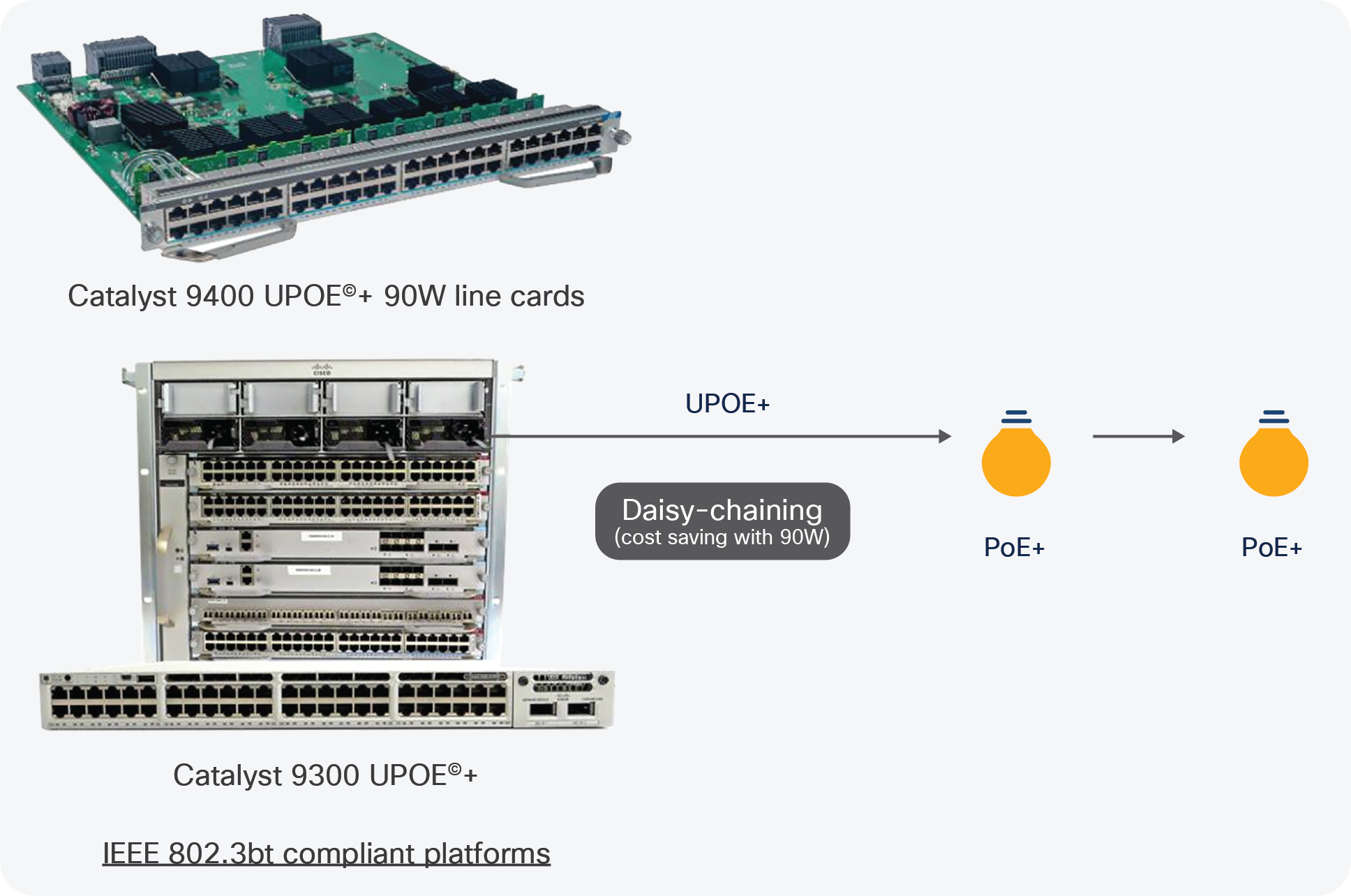
Daisy-chaining use case
Under previous PoE standards, only a few PDs could have been daisy-chained, but with Cisco UPOE+ multiple devices with higher power requirements can be daisy-chained via a single Ethernet port. Instead of daisy- chaining two 30-watt PoE lights, three 30-watt lights can be daisy-chained with Cisco UPOE+, reducing the overall use of switch ports, which in turn will reduce the overall cost. This will also reduce the overall cable footprint and lower the Total Cost of Ownership (TCO).
These use cases are just the start of the revolutionized Digital Building solution and workspace, and this list will continue to grow in the future, including Cisco UPOE+ powered desks and everything in the workspace powered by PoE.
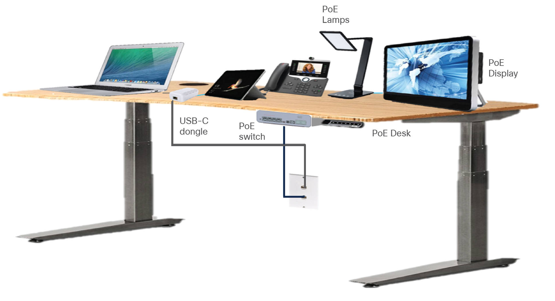
Cisco UPOE+ powered workspace
Introduction to the IEEE 802.3bt standard
Before discussing 802.3bt, let’s look briefly into Cisco UPOE, which was introduced before the 802.3bt standard.
Cisco UPOE uses Cisco Discovery Protocol and Link Layer Discovery Protocol (LLDP) as a device discovery method. Cisco UPOE uses four pairs of twisted-pair Ethernet cables to provide 60 watts (two pairs deliver 30 watts each) from PSE and 54.4 watts to the PDs.
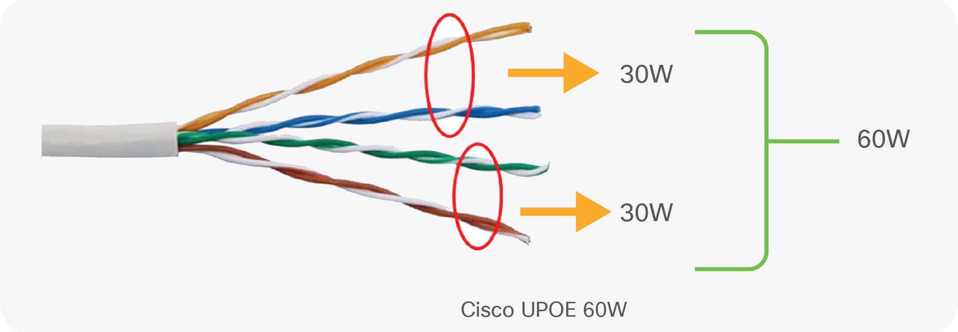
Cisco UPOE cable
The IEEE 802.3bt standard is the latest revision to the broadly adopted IEEE standards for PoE device classification. The amount of power delivered from the PSE is increased by threefold, delivering up to 90 watts to a PD over four pairs of standard Category 5e cables and above. This standard introduces additional types (Type 3 and Type 4) and classes (class 5 to class 8) of PSE and PDs. The PSE output power ranges between 45 and 90 watts, and the PD input power ranges between 40 and 73 watts. It also enables support for dual- signature PDs and single-signature PDs, and also supports power demotion to handle scenarios in which a Type 4 PD is connected to a Type 3 PSE. Type 4 delivers power over all four pairs of Ethernet cables (two pairs deliver 45 watts, totaling up to 90 watts).
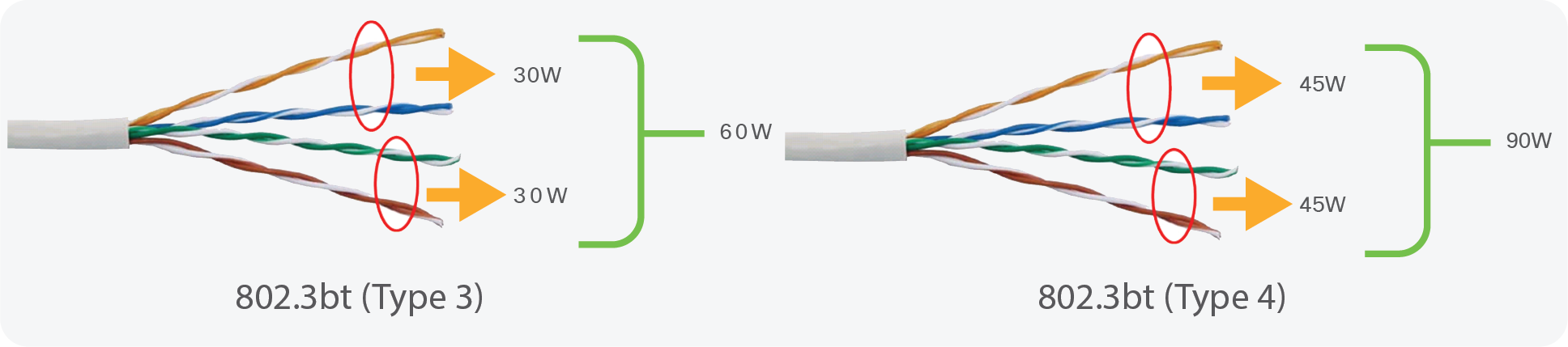
802.3bt Type 3 and Type 4 output
Class
The class defines the maximum power being sourced or drawn in the system. 802.3bt introduces four more classes in addition to previous classes defined by the IEEE 802.3af and 802.3at standards. Type 3 includes two classes (class 5 and class 6), and Type 4 includes classes 7 and 8, where 8 represents the highest power level. Each class defines the maximum power that can be delivered by the PSE to a PD. The power range for each class is shown in Table 1.
Device types
The device type determines the major characteristics of the PSE and PDs. An overview of the types with classes and other details is shown in Table 1 and Figure 7. Type 1 and Type 2 PSEs provide power over only two pairs. Type 3 PSE can provide power on two pairs, supporting all PDs up to Class 4 (25.5 watts), or it can provide power over four pairs, supporting all PDs up to Class 6 (51 watts). Type 4 PSE can provide power over four pairs and can support all PDs up to Class 8 (71.3 watts).
Table 1. PoE types and classes
| Type |
Class |
Power over twisted pairs |
PoE standard |
Maximum power from PSE |
Maximum power to PD |
| 1 |
0 to 3 |
2 pairs |
802.3af (PoE) |
15.4W |
12.95W |
| 2 |
4 |
2 pairs |
802.3at (PoE+) |
30W |
25.5W |
|
|
|
4 pairs |
Cisco UPOE |
60W |
51W |
| 3 |
5, 6 |
4 pairs |
802.3bt (60W) |
60W |
51W |
| 4 |
7, 8 |
4 pairs |
802.3bt (90W) |
90W |
71W |
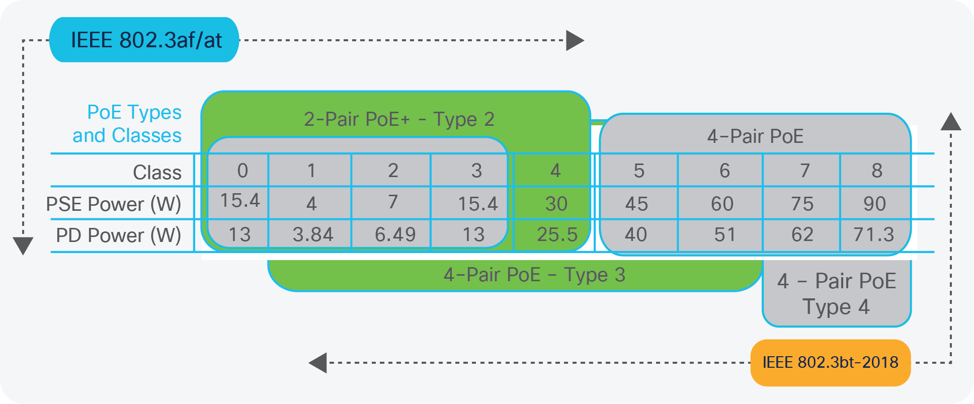
Overview of PoE types and classes
802.3bt startup procedure to negotiate PoE
In this section, only the new implementation of the 802.3bt standard will be discussed, from detection to connection check, power demotion, and standby power.
Detection
One of the most important functions of a PoE system is the detection method, whereby the PSE determines if the remote equipment is capable of receiving power or not. The detection method is similar to that for Type 1 and Type 2 devices, but some detection requirements have been enhanced in the 802.3bt standard.
The resistance of the PD is first measured by the PSE, using at least two voltage/current points, namely effective and absolute. The difference between the two resistance measurements (effective and absolute) is used to evaluate the PD detection. The PSE will then probe the pair set (or pair sets) for a valid PD signature. Power is applied only when a valid PD signature is found. Type 3 and Type 4 capable PSE performs this detection on both pair sets. The requirements for PSE and both of these PD types are quite different.
The standard does not specify a specific method to determine the PD signature; this is considered implementation-specific to the vendor. An implementation can make use of the defined properties to identify single- and dual-signature PDs and make its determination. From the PSE (switch) perspective, it will work with both single- and dual-signature PDs. The following is a brief explanation of single-signature and dual-signature PDs.
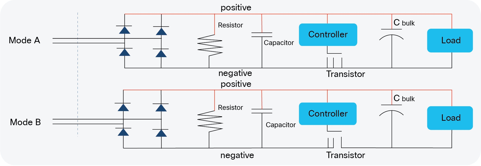
In a single-signature PD, the two pair sets on the cable share a common detect/class circuit. The PD can draw power on both pair sets, and both pairs have the same Maintain Power signature (MPS) and classification and detection signature.
The classification current is shared by the two pair sets (total power = Mode A = Mode B).
Single-signature PD
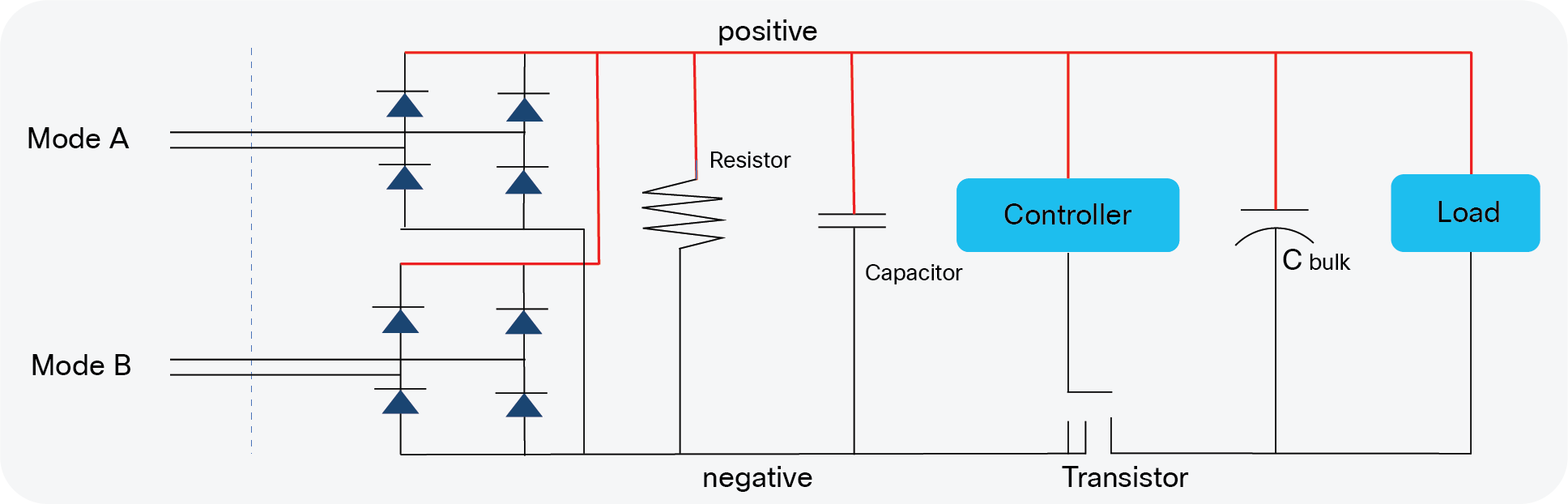
In a dual-signature PD, the two pair sets have independent detect/class circuits. The PD can draw power on both pair sets, and they have independent MPS, with classification and detection on both pairs. Classification currents on each pair set (total power = Mode A + Mode B) – MPS will be enforced on each pair set.
Dual-signature PD
The 802.3bt standard provides the ability to differentiate between single- and dual-signature PDs via the new method of a connection check.
Connection check
Connection check is a mechanism whereby 4-pair-capable PSE probes the PD to find out if it is a single- signature configuration, a dual-signature configuration, or an invalid PD. A connection check can happen before, after, or concurrently with the PD detection.
Detection and connection check exist for different purposes and should not be confused. Detection identifies only whether an attached device is capable of receiving power or not. Connection check determines whether the PD is single-signature or dual-signature. The result of a connection check also helps determine whether a PD may be powered over four pairs and how the PD will be treated by the PSE.
Auto-class and power demotion
Automatic class and power demotion is an optional classification technique that allows the PSE to account for the resistive losses in the cable and optimize the power allocation based on a reference power measurement. This allows the PSE to power more ports from a limited power supply budget. Using this technique, PSE that cannot meet the power demand of a PD can provide it with a lower class. The PD can then operate in a limited mode using the available power. Previously, Type 2 PSEs were not required to support full hardware classification and could instead use LLDP (a protocol over the Ethernet data link) to provide full power to PDs. It is now mandatory for Type 3 and Type 4 PSEs to fully support hardware classification, which leads to a more robust system. LLDP is still used by PDs to fine-tune their power demand.
Short MPS
Short MPS is like a sleep mode that allows PDs to achieve a much lower standby power compared to the existing standards. The minimum standby power has been reduced to one-tenth of what the previous standards allowed (20 milliwatts versus 200 milliwatts). This enables Internet of Things (IoT) devices to be powered with PoE and also have acceptable standby performance.
How to migrate to this new standard
Cisco offers a wide range of PoE switches, ranging from the Cisco Catalyst 9000 family to Cisco Digital Building switches with a complete solution for the ever-increasing number of IoT endpoints. As this paper emphasizes 802.3bt Types 3 and 4, it will touch upon how to migrate to or implement this new standard.
The Catalyst 9000 family offers many PoE options:
Catalyst 9200
| Modular uplink models |
|
| C9200-24P |
24 ports full PoE+ |
| C9200-24PB |
24 ports full PoE+ |
| C9200-24PXG |
24 ports full PoE+ (8 mGig ports up to 10G, 16 ports up to 1G) |
| C9200-48P |
48 ports full PoE+ |
| C9200-48PL |
48 Ports partial PoE+ |
| C9200-48PB |
48 ports full PoE+ |
| C9200-48PXG |
48 ports full PoE+ (8 mGig ports up to 10G, 40 ports up to 1G) |
| Fixed uplink models |
|
| C9200L-24P-4G |
24 ports full PoE+ |
| C9200L-48T-4G |
48 ports data |
| C9200L-48P-4G |
48 ports full POE+ |
| C9200L-48PL-4G |
48 Ports partial PoE+ |
| C9200L-24P-4X |
24 ports full PoE+ |
| C9200L-48P-4X |
48 ports full PoE+ |
| C9200L-48PL-4X |
48 Port partial PoE+ |
| C9200L-24PXG-4X |
24 ports full PoE+ (8 mGig ports up to 10G, 16 ports up to 1G) |
| C9200L-48PXG-4X |
48 ports full POE+ (12 mGig ports up to 10G, 36 ports up to 1G) |
| C9200L-24PXG-2Y |
24 ports full PoE+ (8 mGig ports up to 10G, 16 ports up to 1G) |
| C9200L-48PXG-2Y |
48 ports full POE+ (8 mGig ports up to 10G, 40 ports up to 1G) |
Catalyst 9300
| Modular uplink models |
|
| C9300X-48HX |
48 Cisco UPoE+, 48x 10G Multigigabit (100M, 1G, 2.5G, 5G, or 10 Gbps) w/ 90W UPOE+ |
| C9300X-48HXN |
48 Cisco UPOE+, 8x 10G Multigigabit (100M, 1G, 2.5G, 5G, or 10 Gbps) + 40x 5G Multigigabit (100M/1G/2.5G/5Gbps) |
| C9300X-24HX |
24 Cisco UPOE+, 24x 10G Multigigabit (100M, 1G, 2.5G, 5G, or 10 Gbps) |
| C9300-24P |
24 POE+ |
| C9300-48P |
48 POE+ |
| C9300-24U |
24 Cisco UPOE |
| C9300-48U |
48 Cisco UPOE |
| C9300-24UX |
24 Multigigabit Cisco UPOE |
| C9300-48UXM |
48 Cisco UPOE 36x 100M/1G/2.5G + 12x Multigigabit (100M/1G/2.5G/5G/10Gbps) |
| C9300-48UN |
48 5Gbps UPOE ports (100M/1G/2.5G/5Gbps) |
| C9300-24UB |
24 Cisco UPOE |
| C9300-24UXB |
24 Multigigabit Cisco UPOE (100M/1G/2.5G/5G/10Gbps) |
| C9300-48UB |
48 Cisco UPOE |
| C9300-24H |
24 Cisco UPOE+ |
| C9300-48H |
48 Cisco UPOE+ |
| Fixed Uplinks |
|
| C9300L-24P-4G |
24 PoE+ |
| C9300L-24P-4X |
24 PoE+ |
| C9300L-48P-4G |
48 PoE+ |
| C9300L-48P-4X |
48 PoE+ |
| C9300L-48PF-4G |
48 PoE+ |
| C9300L-48PF-4X |
48 PoE+ |
| C9300L-24UXG-4X |
24 Cisco UPOE 8 Multigigabit (100M/1G/2.5G/5G/10G) + 16x 10M/100M/1G |
| C9300L-24UXG-2Q |
24 Cisco UPOE 8 Multigigabit (100M/1G/2.5G/5G/10G) + 16x 10M/100M/1G |
| C9300L-48UXG-4X |
48 Cisco UPOE 12 Multigigabit (100M/1G/2.5G/5G/10G) + 36x 10M/100M/1G |
| C9300L-48UXG-2Q |
48 Cisco UPOE 12 Multigigabit (100M/1G/2.5G/5G/10G) + 36x 10M/100M/1G |
Catalyst 9400
| Catalyst 9400 line cards |
|
| C9400-LC-48HX |
48 ports 10 Gbps multigigabit, UPOE+ |
| C9400-LC-48HN |
48 ports 5 Gbps multigigabit, UPOE+ |
| C9400-LC-48H |
48 ports 1 Gbps, UPOE+ |
| C9400-LC-48UX |
24 ports 5Gbps multigigabit, 24 ports 1G, UPOE |
| C9400-LC-48U |
48 ports 1 Gbps, UPOE |
| C9400-LC-48P |
48 ports 1 Gbps, PoE+ |
When using Cisco UPOE line cards or switches that support up to 60 watts per port, the following command is required to convert these switches or line cards into Type 3 802.3bt compliance mode:
hw-module slot#/switch# upoe-plus
Example:
Check the show module CLI output in Figure 11. There are two PoE line cards in the switch, a 48-port Cisco UPOE line card (C9400-LC-48UX) and a 48-port 90-watt BT line card (C9400-LC-48H). The 90-watt BT line card in slot 4 supports 802.3bt Type 3 and Type 4 by default and no CLI is required, as was mentioned earlier. However, the 48-port Cisco UPOE line card (C9400-LC-48UX) in slot 1 requires conversion to support 802.3bt Type 3.
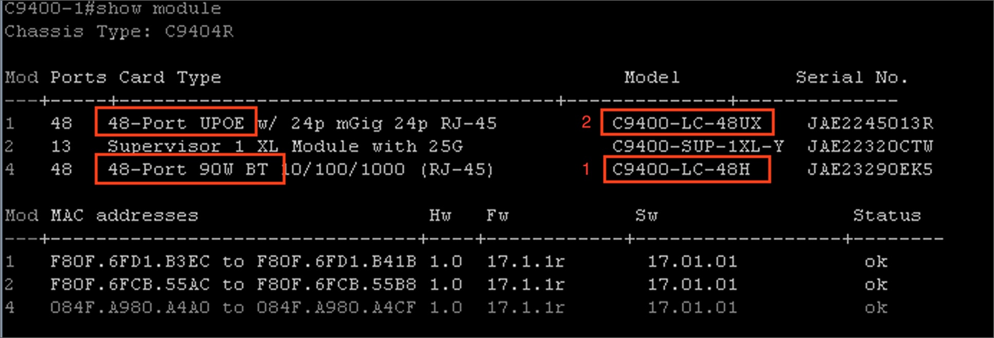
show module output
Once the command (hw-module slot 1 upoe-plus) is executed, Online Insertion and Removal (OIR) is performed on the slot and only the specified line card resets. There is no need to reload the switch or physically remove or reinsert the line card. The output can be seen in Figure 12.
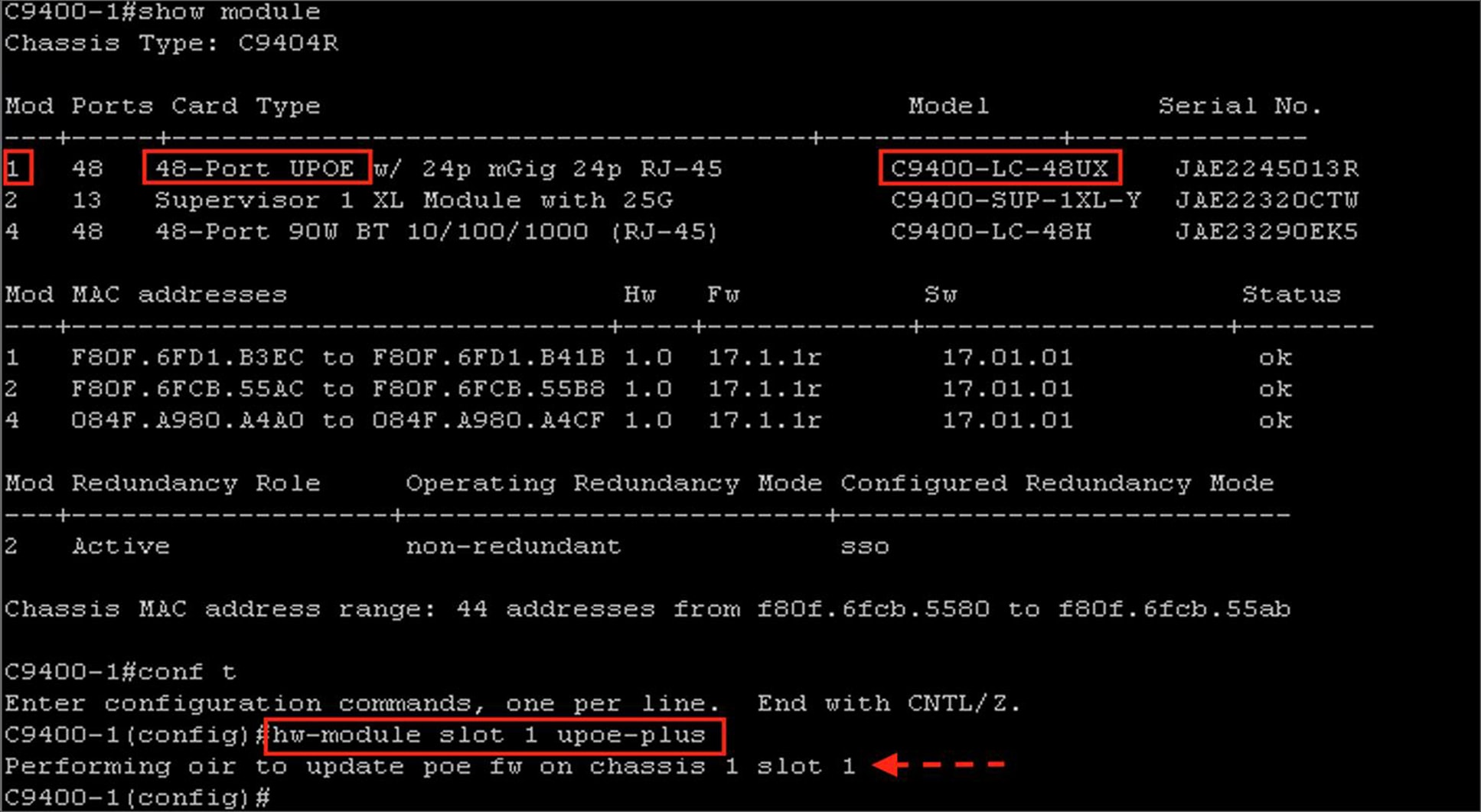
Output after conversion of line card
Cabling requirements for the IEEE 802.3bt standard
IEEE 802.3bt standard use all eight conductors in the Ethernet cable to carry current. A minimum of Category 5e cable is needed, but it’s better to use Category 6A/7A 4-pair balanced twisted-pair cable with new 90-watt PoE installations for the best possible thermal and power efficiency.
For 802.3bt Type 4 installations specific to lighting and applications that are concerned with maximum power transmission efficiency and low data speed installs (i.e., 1Gbps or less), Cisco recommends 22AWG conductors in the cable with a minimum of Cat 5e cable. For IEEE 802.3bt Type 4 installations requiring higher data speeds, it is recommended to use Cat 6a with 23AWG or larger conductors
If the installation does not use the recommended cable, the following are other options that comply with the National Electrical Code (NEC):
● Cables with 24AWG conductors rated at 60 ℃, in bundle sizes of 37 or less
● Cables with 23AWG conductors rated at 60 ℃, in bundle sizes of 61 or less
● Cables with 24AWG conductors rated at 75 ℃, in bundle sizes of 91 or less
● Cables with 23AWG conductors rated at 75 ℃, in bundle sizes of 192 or less
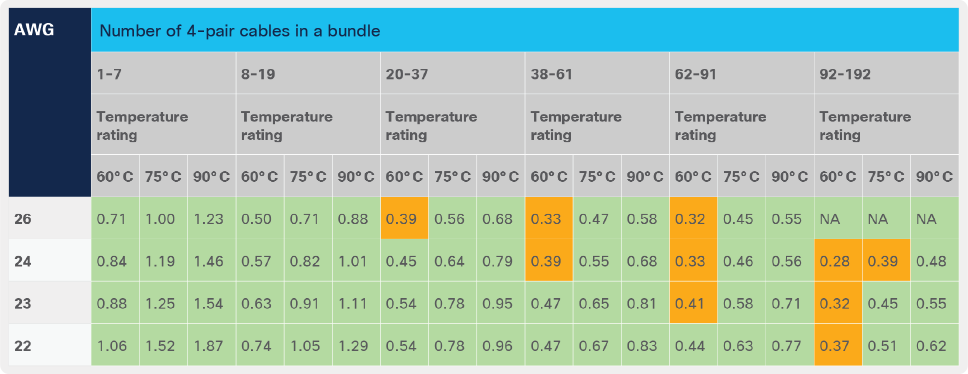
Table 2 is derived from NEC 2020, Table 725.144, adjusted for 45°C ambient temperature using 310.15(B). The values in the green cells are accepted values for IEEE Type 4 PoE systems. Type 4 systems are limited to 0.433A per conductor.
Table 2. NEC 2020 Table 725.144 adjusted for 45°C ambient temperature
802.3bt opens a new chapter in PoE-powered endpoints. In short, it introduces two new types, Type 3 and Type 4 PSE and PDs, working over four pairs on Ethernet cable with additional classes (5 to 8); brings automatic class functionality; supports single-signature and dual-signature PDs; offers extended power capability if the channel length is known; and supports low standby power. Although the technology is relatively new, there are already PDs, such as HD cameras, light fixtures, all-in-one computers, and other use cases that can be powered up and fulfilled by leveraging this new standard. We see more use cases in the future, and the only thing that will need to be replaced is the switch, as long as the cable infrastructure supports Category 5e and above cables that follow NEC specifications. In most of the cases, even if the installation does not use cables that meet the recommended requirements, there are still options that will only reduce the cable bundle size, so there is no extra cooling requirement or replacement of infrastructure. All that is needed is to replace the switch and save big on cabling budget without a need to replace PDs, as Cisco switches are compatible with all previous industry standards and Cisco UPOE.
The global IoT market is growing at a very fast pace, which brings concerns and challenges regarding management, security, and compliance. All of these can be securely handled by Cisco DNA Center and Identity Services Engine (ISE). Cisco also has solutions such as Manufacturer Usage Description (MUD), which the network uses to sort out what kind of access and network functionality the endpoint requires in order to function properly. Network operators can segment the network and at the same time device manufacturers can, thus enhancing the security of their devices and together advancing into the new era of IT and OT convergence.
● Cisco UPOE+ with Cisco Catalyst 9000 Switches Deployment Guide
● IEEE