Asset Visibility
Administrative Access to Cisco ISE Using an External Identity Store
In Cisco ISE, you can authenticate administrators via an external identity store such as Active Directory, LDAP, or RSA SecureID. There are two models you can use to provide authentication via an external identity store:
-
External Authentication and Authorization—There are no credentials that are specified in the local Cisco ISE database for the administrator, and authorization is based on external identity store group membership only. This model is used for Active Directory and LDAP authentication.
-
External Authentication and Internal Authorization—The administrator’s authentication credentials come from the external identity source, and authorization and administrator role assignment take place using the local Cisco ISE database. This model is used for RSA SecurID authentication. This method requires you to configure the same username in both the external identity store and the local Cisco ISE database.
During the authentication process, Cisco ISE is designed to “fall back” and attempt to perform authentication from the internal identity database, if communication with the external identity store has not been established or if it fails. In addition, whenever an administrator for whom you have set up external authentication launches a browser and initiates a login session, the administrator still has the option to request authentication via the Cisco ISE local database by choosing “Internal” from the Identity Store drop-down selector in the login dialog.
Administrators who belong to a Super Admin group, and are configured to authenticate and authorize using an external identity store, can also authenticate with the external identity store for CLI access.
 Note |
You can configure this method of providing external administrator authentication only via the Admin portal. The Cisco ISE Command Line Interface (CLI) does not feature these functions. |
If your network does not already have one or more existing external identity stores, ensure that you have installed the necessary external identity stores and configured Cisco ISE to access those identity stores.
External Authentication and Authorization
By default, Cisco ISE provides internal administrator authentication. To set up external authentication, you must create a password policy for the external administrator accounts that you define in the external identity stores. You can then apply this policy to the external administrator groups that eventually become a part of the external administrator RBAC policy.
In addition to providing authentication via an external identity store, your network may also require you to use a Common Access Card (CAC) authentication device.
To configure external authentication, you must:
-
Configure password-based authentication using an external identity store.
-
Create an external administrator group.
-
Configure menu access and data access permissions for the external administrator group.
-
Create an RBAC policy for external administrator authentication.
Configure a Password-Based Authentication Using an External Identity Store
You must first configure password-based authentication for administrators who authenticate using an external identity store such as Active Directory or LDAP.
Procedure
| Step 1 |
Choose . |
| Step 2 |
On the Authentication Method tab, select Password Based and choose one of the external identity sources you should have already configured. For example, the Active Directory instance that you have created. |
| Step 3 |
Configure any other specific password policy settings that you want for administrators who authenticate using an external identity store. |
| Step 4 |
Click Save. |
Create an External Administrator Group
You will need to create an external Active Directory or LDAP administrator group. This ensures that Cisco ISE uses the username that is defined in the external Active Directory or LDAP identity store to validate the administrator username and password that you entered upon login.
Cisco ISE imports the Active Directory or LDAP group information from the external resource and stores it as a dictionary attribute. You can then specify that attribute as one of the policy elements when it is time to configure the RBAC policy for this external administrator authentication method.
Procedure
| Step 1 |
Choose Administration > System > Admin Access > Administrators > Admin Groups. The External Groups Mapped column displays the number of external groups that are mapped to internal RBAC roles. You can click the number corresponding to a admin role to view the external groups (for example, if you click 2 displayed against Super Admin, the names of two external groups are displayed). |
| Step 2 |
Click Add. |
| Step 3 |
Enter a name and optional description. |
| Step 4 |
Choose the External radio button. If you have connected and joined to an Active Directory domain, your Active Directory instance name appears in the Name field. |
| Step 5 |
From the External Groups drop-down list box, choose the Active Directory group that you want to map for this external administrator group. Click the “+” sign to map additional Active Directory groups to this external administrator group. |
| Step 6 |
Click Save. |
Create an Internal Read-Only Admin
Procedure
| Step 1 |
Choose . |
| Step 2 |
Click Add and select Create An Admin User. |
| Step 3 |
Check the Read Only check box to create a Read-Only administrator. |
Map External Groups to the Read-Only Admin Group
Procedure
| Step 1 |
Choose Administration > Identity Management > External Identity Sources to configure the external authentication source. See the Manage Users and External Identity Sources chapter for more information. |
| Step 2 |
Click the required external identity source, such as Active Directory or LDAP, and then retrieve the groups from the selected identity source. |
| Step 3 |
Choose Administration > System > Admin Access > Authentication to map the authentication method for the admin access with the identity source. |
| Step 4 |
Choose Administration > System > Admin Access > Administrators > Admin Groups and select Read Only Admin group. |
| Step 5 |
Check the Type External check box and select the required external groups for whom you intend to provide read-only privileges. |
| Step 6 |
Click Save. An external group that is mapped to a Read-Only Admin group cannot be assigned to any other admin group.
|
Configure Menu Access and Data Access Permissions for the External Administrator Group
You must configure menu access and data access permissions that can be assigned to the external administrator group.
Procedure
| Step 1 |
Choose . |
| Step 2 |
Click one of the following:
|
| Step 3 |
Specify menu access or data access permissions for the external administrator group. |
| Step 4 |
Click Save. |
Create an RBAC Policy for External Administrator Authentication
In order to configure Cisco ISE to authenticate the administrator using an external identity store and to specify custom menu and data access permissions at the same time, you must configure a new RBAC policy. This policy must have the external administrator group for authentication and the Cisco ISE menu and data access permissions to manage the external authentication and authorization.
Note |
You cannot modify an existing (system-preset) RBAC policy to specify these new external attributes. If you have an existing policy that you would like to use as a “template,” be sure to duplicate that policy, rename it, and then assign the new attributes. |
Procedure
| Step 1 |
Choose . |
| Step 2 |
Specify the rule name, external administrator group, and permissions. Remember that the appropriate external administrator group must be assigned to the correct administrator user IDs. Ensure that the administrator in question is associated with the correct external administrator group. |
| Step 3 |
Click Save. If you log in as an administrator, and the Cisco ISE RBAC policy is not able to authenticate your administrator identity, Cisco ISE displays an “unauthenticated” message, and you cannot access the Admin portal. |
Configure Admin Access Using an External Identity Store for Authentication with Internal Authorization
This method requires you to configure the same username in both the external identity store and the local Cisco ISE database. When you configure Cisco ISE to provide administrator authentication using an external RSA SecurID identity store, administrator credential authentication is performed by the RSA identity store. However, authorization (policy application) is still done according to the Cisco ISE internal database. In addition, there are two important factors to remember that are different from external authentication and authorization:
-
You do not need to specify any particular external administrator groups for the administrator.
-
You must configure the same username in both the external identity store and the local Cisco ISE database.
Procedure
| Step 1 |
Choose . |
||
| Step 2 |
Ensure that the administrator username in the external RSA identity store is also present in Cisco ISE. Ensure that you click the External option under Password.
|
||
| Step 3 |
Click Save. |
External Authentication Process Flow
When the administrator logs in, the login session passes through the following steps in the process:
-
The administrator sends an RSA SecurID challenge.
-
RSA SecurID returns a challenge response.
-
The administrator enters a user name and the RSA SecurID challenge response in the Cisco ISE login dialog, as if entering the user ID and password.
-
The administrator ensures that the specified Identity Store is the external RSA SecurID resource.
-
The administrator clicks Login.
Upon logging in, the administrator sees only the menu and data access items that are specified in the RBAC policy.
External Identity Sources
These pages enable you to configure and manage external identity sources that contain user data that Cisco ISE uses for authentication and authorization.
LDAP Identity Source Settings
The following table describes the fields on the LDAP Identity Sources page, which you can use to create an LDAP instance and connect to it. The navigation path for this page is: .
LDAP General Settings
The following table describes the fields in the General tab.
|
Fields |
Usage Guidelines |
||
|---|---|---|---|
|
Name |
Enter a name for the LDAP instance. This value is used in searches to obtain the subject DN and attributes. The value is of type string and the maximum length is 64 characters. |
||
|
Description |
Enter a description for the LDAP instance. This value is of type string, and has a maximum length of 1024 characters. |
||
|
Schema |
You can choose any one of the following built-in schema types or create a custom schema:
|
||
|
|||
|
Subject Objectclass |
Enter a value to be used in searches to obtain the subject DN and attributes. The value is of type string and the maximum length is 256 characters. |
||
|
Subject Name Attribute |
Enter the name of the attribute containing the username in the request. The value is of type string and the maximum length is 256 characters. |
||
|
Group Name Attribute |
Enter CN or DN or any supported attribute in the Group Name Attribute field.
|
||
|
Certificate Attribute |
Enter the attribute that contains the certificate definitions. For certificate-based authentication, these definitions are used to validate certificates that are presented by clients. |
||
|
Group Objectclass |
Enter a value to be used in searches to specify the objects that are recognized as groups. The value is of type string and the maximum length is 256 characters. |
||
|
Group Map Attribute |
Specifies the attribute that contains the mapping information. This attribute can be a user or group attribute based on the reference direction that is chosen. |
||
|
Subject Objects Contain Reference To Groups |
Click this radio button if the subject objects contain an attribute that specifies the group to which they belong. |
||
|
Group Objects Contain Reference To Subjects |
Click this radio button if the group objects contain an attribute that specifies the subject. This value is the default value. |
||
|
Subjects in Groups Are Stored in Member Attribute As |
(Only available when you select the Group Objects Contain Reference To Subjects radio button) Specifies how members are sourced in the group member attribute and defaults to the DN. |
||
|
User Info Attributes |
By default, predefined attributes are used to collect user information (such as, first name, last name, email, telephone, locality, and so on) for the following built-in schema types:
If you edit the attributes of the predefined schema, Cisco ISE automatically creates a Custom schema. You can also select the Custom option from the Schema drop-down list to edit the user information attributes based on your requirements. |
||
LDAP Connection Settings
The following table describes the fields in the Connection Settings tab.
|
Fields |
Usage Guidelines |
|---|---|
|
Enable Secondary Server |
Check this option to enable the secondary LDAP server to be used as a backup if the primary LDAP server fails. If you check this check box, you must enter configuration parameters for the secondary LDAP server. |
|
Primary and Secondary Servers |
|
|
Hostname/IP |
Enter the IP address or DNS name of the machine that is running the LDAP software. The hostname can contain from 1 to 256 characters or a valid IP address expressed as a string. The only valid characters for hostnames are alphanumeric characters (a to z, A to Z, 0 to 9), the dot (.), and the hyphen (-). |
|
Port |
Enter the TCP/IP port number on which the LDAP server is listening. Valid values are from 1 to 65,535. The default is 389, as stated in the LDAP specification. If you do not know the port number, you can find this information from the LDAP server administrator. |
|
Specify server for each ISE node |
Check this check box to configure primary and secondary LDAP server hostnames/IP and their ports for each PSN. When this option is enabled, a table listing all the nodes in the deployment is displayed. You need to select the node and configure the primary and secondary LDAP server hostname/IP and their ports for the selected node. |
|
Access |
Anonymous Access—Click to ensure that searches on the LDAP directory occur anonymously. The server does not distinguish who the client is and will allow the client read access to any data that is configured as accessible to any unauthenticated client. In the absence of a specific policy permitting authentication information to be sent to a server, a client should use an anonymous connection. Authenticated Access—Click to ensure that searches on the LDAP directory occur with administrative credentials. If so, enter information for the Admin DN and Password fields. |
|
Admin DN |
Enter the DN of the administrator. The Admin DN is the LDAP account that has permission to search all required users under the User Directory Subtree and to search groups. If the administrator specified does not have permission to see the group name attribute in searches, group mapping fails for users who are authenticated by that LDAP server. |
|
Password |
Enter the LDAP administrator account password. |
|
Secure Authentication |
Click to use SSL to encrypt communication between Cisco ISE and the primary LDAP server. Verify that the Port field contains the port number used for SSL on the LDAP server. If you enable this option, you must choose a root CA. |
|
LDAP Server Root CA |
Choose a trusted root certificate authority from the drop-down list to enable secure authentication with a certificate. |
|
Server Timeout |
Enter the number of seconds that Cisco ISE waits for a response from the primary LDAP server before determining that the connection or authentication with that server has failed. Valid values are 1 to 99. The default is 10. |
|
Max. Admin Connections |
Enter the maximum number of concurrent connections (greater than 0) with LDAP administrator account permissions that can run for a specific LDAP configuration. These connections are used to search the directory for users and groups under the User Directory Subtree and the Group Directory Subtree. Valid values are 1 to 99. The default is 20. |
|
Force reconnect every N seconds |
Check this check box and enter the desired value in the Seconds text box to force the server to renew LDAP connection at the specified time interval. The valid range is from 1 to 60 minutes. |
|
Test Bind to Server |
Click to test and ensure that the LDAP server details and credentials can successfully bind. If the test fails, edit your LDAP server details and retest. |
|
Failover |
|
|
Always Access Primary Server First |
Click this option if you want Cisco ISE to always access the primary LDAP server first for authentications and authorizations. |
|
Failback to Primary Server After |
If the primary LDAP server that Cisco ISE attempts to contact cannot be reached, Cisco ISE attempts to contact the secondary LDAP server. If you want Cisco ISE to use the primary LDAP server again, click this option and enter a value in the text box. |
LDAP Directory Organization Settings
The following table describes the fields in the Directory Organization tab.
|
Fields |
Usage Guidelines |
||
|---|---|---|---|
|
Subject Search Base |
Enter the DN for the subtree that contains all subjects. For example: o=corporation.com If the tree containing subjects is the base DN, enter: o=corporation.com or dc=corporation,dc=com as applicable to your LDAP configuration. For more information, refer to your LDAP database documentation. |
||
|
Group Search Base |
Enter the DN for the subtree that contains all groups. For example: ou=organizational unit, ou=next organizational unit, o=corporation.com If the tree containing groups is the base DN, type: o=corporation.com or dc=corporation,dc=com as applicable to your LDAP configuration. For more information, refer to your LDAP database documentation. |
||
|
Search for MAC Address in Format |
Enter a MAC Address format for Cisco ISE to use for search in the LDAP database. MAC addresses in internal identity sources are sourced in the format xx-xx-xx-xx-xx-xx. MAC addresses in LDAP databases can be sourced in different formats. However, when Cisco ISE receives a host lookup request, Cisco ISE converts the MAC address from the internal format to the format that is specified in this field. Use the drop-down list to enable searching for MAC addresses in a specific format, where <format> can be any one of the following:
The format you choose must match the format of the MAC address sourced in the LDAP server. |
||
|
Strip Start of Subject Name Up To the Last Occurrence of the Separator |
Enter the appropriate text to remove domain prefixes from usernames. If, in the username, Cisco ISE finds the delimiter character that is specified in this field, it strips all characters from the beginning of the username through the delimiter character. If the username contains more than one of the characters that are specified in the <start_string> box, Cisco ISE strips characters through the last occurrence of the delimiter character. For example, if the delimiter character is the backslash (\) and the username is DOMAIN\user1, Cisco ISE submits user1 to an LDAP server.
|
||
|
Strip End of Subject Name from the First Occurrence of the Separator |
Enter the appropriate text to remove domain suffixes from usernames. If, in the username, Cisco ISE finds the delimiter character that is specified in this field, it strips all characters from the delimiter character through the end of the username. If the username contains more than one of the characters that are specified in this field, Cisco ISE strips characters starting with the first occurrence of the delimiter character. For example, if the delimiter character is @ and the username is user1@domain, then Cisco ISE submits user1 to the LDAP server.
|
LDAP Group Settings
|
Fields |
Usage Guidelines |
|---|---|
|
Add |
Choose Add > Add Group to add a new group or choose Add > Select Groups From Directory to select the groups from the LDAP directory. If you choose to add a group, enter a name for the new group. If you are selecting from the directory, enter the filter criteria, and click Retrieve Groups. Check the check boxes next to the groups that you want to select and click OK. The groups that you have selected will appear in the Groups page. |
LDAP Attribute Settings
|
Fields |
Usage Guidelines |
|---|---|
|
Add |
Choose Add > Add Attribute to add a new attribute or choose Add > Select Attributes From Directory to select attributes from the LDAP server. If you choose to add an attribute, enter a name for the new attribute. If you are selecting from the directory, enter the username and click Retrieve Attributes to retrieve the user’s attributes. Check the check boxes next to the attributes that you want to select, and then click OK. |
LDAP Advanced Settings
The following table describes the field in the Advanced Settings tab.
|
Fields |
Usage Guidelines |
|---|---|
|
Enable Password Change |
Check this check box to enable the user to change the password in case of password expiry or password reset while using PAP protocol for device admin and RADIUS EAP-GTC protocol for network access. User authentication fails for the unsupported protocols. This option also enables the user to change the password on their next login. |
RADIUS Token Identity Sources Settings
| Fields | Usage Guidelines |
|---|---|
|
Name |
Enter a name for the RADIUS token server. The maximum number of characters allowed is 64. |
|
Description |
Enter a description for the RADIUS token server. The maximum number of characters is 1024. |
|
SafeWord Server |
Check this check box if your RADIUS identity source is a SafeWord server. |
|
Enable Secondary Server |
Check this check box to enable the secondary RADIUS token server for Cisco ISE to use as a backup in case the primary fails. If you check this check box, you must configure a secondary RADIUS token server. |
|
Always Access Primary Server First |
Click this radio button if you want Cisco ISE to always access the primary server first. |
|
Fallback to Primary Server after |
Click this radio button to specify the amount of time in minutes that Cisco ISE can authenticate using the secondary RADIUS token server if the primary server cannot be reached. After this time elapses, Cisco ISE reattempts to authenticate against the primary server. |
| Primary Server | |
|
Host IP |
Enter the IP address of the primary RADIUS token server. This field can take as input a valid IP address that is expressed as a string. Valid characters that are allowed in this field are numbers and dot (.). |
|
Shared Secret |
Enter the shared secret that is configured on the primary RADIUS token server for this connection. |
|
Authentication Port |
Enter the port number on which the primary RADIUS token server is listening. |
|
Server Timeout |
Specify the time in seconds that Cisco ISE should wait for a response from the primary RADIUS token server before it determines that the primary server is down. |
|
Connection Attempts |
Specify the number of attempts that Cisco ISE should make to reconnect to the primary server before moving on to the secondary server (if defined) or dropping the request if a secondary server is not defined. |
| Secondary Server | |
|
Host IP |
Enter the IP address of the secondary RADIUS token server. This field can take as input a valid IP address that is expressed as a string. Valid characters that are allowed in this field are numbers and dot (.). |
|
Shared Secret |
Enter the shared secret configured on the secondary RADIUS token server for this connection. |
|
Authentication Port |
Enter the port number on which the secondary RADIUS token server is listening. Valid values are from 1 to 65,535. The default is 1812. |
|
Server Timeout |
Specify the time in seconds that Cisco ISE should wait for a response from the secondary RADIUS token server before it determines that the secondary server is down. |
|
Connection Attempts |
Specify the number of attempts that Cisco ISE should make to reconnect to the secondary server before dropping the request. |
RSA SecurID Identity Source Settings
RSA Prompt Settings
The following table describes the fields in the RSA Prompts tab.
|
Fields |
Usage Guidelines |
|---|---|
|
Enter Passcode Prompt |
Enter a text string to obtain the passcode. |
|
Enter Next Token Code |
Enter a text string to request the next token. |
|
Choose PIN Type |
Enter a text string to request the PIN type. |
|
Accept System PIN |
Enter a text string to accept the system-generated PIN. |
|
Enter Alphanumeric PIN |
Enter a text string to request an alphanumeric PIN. |
|
Enter Numeric PIN |
Enter a text string to request a numeric PIN. |
|
Re-enter PIN |
Enter a text string to request the user to re-enter the PIN. |
RSA Message Settings
The following table describes the fields in the RSA Messages tab.
|
Fields |
Usage Guidelines |
|---|---|
|
Display System PIN Message |
Enter a text string to label the system PIN message. |
|
Display System PIN Reminder |
Enter a text string to inform the user to remember the new PIN. |
|
Must Enter Numeric Error |
Enter a message that instructs users to enter only numbers for the PIN. |
|
Must Enter Alpha Error |
Enter a message that instructs users to enter only alphanumeric characters for PINs. |
|
PIN Accepted Message |
Enter a message that the users see when their PIN is accepted by the system. |
|
PIN Rejected Message |
Enter a message that the users see when the system rejects their PIN. |
|
User Pins Differ Error |
Enter a message that the users see when they enter an incorrect PIN. |
|
System PIN Accepted Message |
Enter a message that the users see when the system accepts their PIN. |
|
Bad Password Length Error |
Enter a message that the users see when the PIN that they specify does not fall within the range specified in the PIN length policy. |
Cisco ISE Users
In this chapter, the term user refers to employees and contractors who access the network regularly as well as sponsor and guest users. A sponsor user is an employee or contractor of the organization who creates and manages guest-user accounts through the sponsor portal. A guest user is an external visitor who needs access to the organization’s network resources for a limited period of time.
You must create an account for any user to gain access to resources and services on the Cisco ISE network. Employees, contractors, and sponsor users are created from the Admin portal.
User Identity
User identity is like a container that holds information about a user and forms their network access credentials. Each user’s identity is defined by data and includes: a username, e-mail address, password, account description, associated administrative group, user group, and role.
User Groups
User groups are a collection of individual users who share a common set of privileges that allow them to access a specific set of Cisco ISE services and functions.
User Identity Groups
A user’s group identity is composed of elements that identify and describe a specific group of users that belong to the same group. A group name is a description of the functional role that the members of this group have. A group is a listing of the users that belong to this group.
Default User Identity Groups
Cisco ISE comes with the following predefined user identity groups:
-
Employee—Employees of your organization belong to this group.
-
SponsorAllAccount—Sponsor users who can suspend or reinstate all guest accounts in the Cisco ISE network.
-
SponsorGroupAccounts—Sponsor users who can suspend guest accounts created by sponsor users from the same sponsor user group.
-
SponsorOwnAccounts—Sponsor users who can only suspend the guest accounts that they have created.
-
Guest—A visitor who needs temporary access to resources in the network.
-
ActivatedGuest—A guest user whose account is enabled and active.
User Role
A user role is a set of permissions that determine what tasks a user can perform and what services they can access on the Cisco ISE network. A user role is associated with a user group. For example, a network access user.
User Account Custom Attributes
Cisco ISE allows you to restrict network access based on user attributes for both network access users and administrators. Cisco ISE comes with a set of predefined user attributes and also allows you to create custom attributes. Both types of attributes can be used in conditions that define the authentication policy. You can also define a password policy for user accounts so that passwords meet specified criteria.
Custom User Attributes
You can configure more user-account attributes on the User Custom Attributes page (Administration > Identity Management > Settings > User Custom Attributes). You can also view the list of predefined user attributes on this page. You cannot edit the predefined user attributes.
Enter the required details in the User Custom Attributes pane to add a new custom attribute. The custom attributes and the default values that you add on the User Custom Attributes page are displayed while adding or editing a Network Access user (Administration > Identity Management > Identities > Users > Add/Edit) or Admin user (Administration > System > Admin Access > Administrators > Admin Users > Add/Edit). You can change the default values while adding or editing a Network Access or Admin user.
You can select the following data types for the custom attributes on the User Custom Attributes page:
-
String—You can specify the maximum string length (maximum allowed length for a string attribute value).
-
Integer—You can configure the minimum and maximum value (specifies the lowest and the highest acceptable integer value).
-
Enum—You can specify the following values for each parameter:
-
Internal value
-
Display value
You can also specify the default parameter. The values that you add in the Display field are displayed while adding or editing a Network Access or Admin user.
-
-
Float
-
Password—You can specify the maximum string length.
-
Long—You can configure the minimum and maximum value.
-
IP—You can specify a default IPv4 or IPv6 address.
-
Boolean—You can set either True or False as the default value.
-
Date—You can select a date from the calendar and set it as the default value. The date is displayed in yyyy-mm-dd format.
Check the Mandatory check box if you want to make an attribute mandatory while adding or editing a Network Access or Admin user. You can also set default values for the custom attributes.
The custom attributes can be used in the authentication policies. The data type and the allowable range that you set for the custom attributes are applied to the custom attribute values in the policy conditions.
Generate Automatic Password for Users and Administrators
Cisco ISE introduces a Generate Password option on the user and administrator creation page to generate instant password adhering to Cisco ISE password policies. This helps the users or administrators to use the password generated by Cisco ISE than spending time in thinking of a safe password to be configured.
-
Users—Administration > Identity Management > Identities > Users.
-
Administrators—Administration > System > Admin Access > Administrators > Admin Users.
-
Logged in Administrator(Current Administrator)—Settings > Account Settings > Change Password.
Internal User Operations
Add Users
Cisco ISE allows you to view, create, modify, duplicate, delete, change the status, import, export, or search for attributes of Cisco ISE users.
If you are using a Cisco ISE internal database, you must create an account for any new user who needs access to resources or services on a Cisco ISE network.
Procedure
| Step 1 |
Choose . You can also create users by accessing the page. |
| Step 2 |
Click Add (+) to create a new user. |
| Step 3 |
Enter values for the fields. Do not include !, %, :, ;, [, {, |, }, ], `, ?, =, <, >, \ and control characters in the username. Username with only spaces
is also not allowed. If you use the Cisco ISE Internal Certificate Authority (CA) for BYOD, the username that you provide here is used as the Common
Name for the endpoint certificate. Cisco ISE Internal CA does not support "+" or "*" characters in the Common Name field.
|
| Step 4 |
Click Submit to create a new user in the Cisco ISE internal database. |
Export Cisco ISE User Data
You might have to export user data from the Cisco ISE internal database. Cisco ISE allows you to export user data in the form of a password-protected csv file.
Procedure
| Step 1 |
Choose . |
| Step 2 |
Check the check box that corresponds to the user(s) whose data you want to export. |
| Step 3 |
Click Export Selected. |
| Step 4 |
Enter a key for encrypting the password in the Key field. |
| Step 5 |
Click Start Export to create a users.csv file. |
| Step 6 |
Click OK to export the users.csv file. |
Import Cisco ISE Internal Users
You can import new user data into ISE with a csv file to create new internal accounts. A template csv file is available for download on the pages where you can import user accounts. You can import users on . Sponsors can import users on the Sponsor portal. The Sponsor Portal Guide tells Sponsors how to import guest accounts. See the Configure Account Content for Sponsor Account Creation section in Cisco ISE Admin Guide: Guest and BYOD for information about configuring the information types that the sponsor guest accounts use.
Note |
If the csv file contains custom attributes, the data type and the allowable range that you set for the custom attributes will be applied for the custom attribute values during import. |
Procedure
| Step 1 |
Choose . |
| Step 2 |
Click Import to import users from a comma-delimited text file. If you do not have a comma-delimited text file, click Generate a Template to create a csv file with the heading rows filled in. |
| Step 3 |
In the File text box, enter the filename containing the users to import, or click Browse and navigate to the location where the file resides. |
| Step 4 |
Check the Create new user(s) and update existing user(s) with new data check boxes if you want to both create new users and update existing users. |
| Step 5 |
Click Save to save your changes to the Cisco ISE internal database. |
Note |
We recommend that you do not delete all the network access users at a time, because this may lead to CPU spike and the services to crash, especially if you are using a very large database. |
Endpoint Settings
The following table describes the fields on the Endpoints page, which you can use to create endpoints and assign policies for endpoints. The navigation path for this page is: .
|
Fields |
Usage Guidelines |
|---|---|
|
MAC Address |
Enter the MAC address in hexadecimal format to create an endpoint statically. The MAC address is the device identifier for the interface that is connected to the Cisco ISE enabled network |
|
Static Assignment |
Check this check box when you want to create an endpoint statically in the Endpoints page and the status of static assignment is set to static. You can toggle the status of static assignment of an endpoint from static to dynamic or from dynamic to static. |
|
Policy Assignment |
(Disabled by default unless the Static Assignment is checked) Choose a matching endpoint policy from the Policy Assignment drop-down list. You can do one of the following:
|
|
Static Group Assignment |
(Disabled by default unless the Static group Assignment is checked) Check this check box when you want to assign an endpoint to an identity group statically. In you check this check box, the profiling service does not change the endpoint identity group the next time during evaluation of the endpoint policy for these endpoints, which were previously assigned dynamically to other endpoint identity groups. If you uncheck this check box, then the endpoint identity group is dynamic as assigned by the ISE profiler based on policy configuration. If you do not choose the Static Group Assignment option, then the endpoint is automatically assigned to the matching identity group the next time during evaluation of the endpoint policy. |
|
Identity Group Assignment |
Choose an endpoint identity group to which you want to assign the endpoint. You can assign an endpoint to an identity group when you create an endpoint statically, or when you do not want to use the Create Matching Identity Group option during evaluation of the endpoint policy for an endpoint. Cisco ISE includes the following system created endpoint identity groups:
|
Endpoint Import from LDAP Settings
The following table describes the fields on the Import from LDAP page, which you can use to import endpoints from an LDAP server. The navigation path for this page is: .
|
Fields |
Usage Guidelines |
||
|---|---|---|---|
|
Connection Settings |
|||
|
Host |
Enter the hostname, or the IP address of the LDAP server. |
||
|
Port |
Enter the port number of the LDAP server. You can use the default port 389 to import from an LDAP server, and the default port 636 to import from an LDAP server over SSL.
|
||
|
Enable Secure Connection |
Check the Enable Secure Connection check box to import from an LDAP server over SSL. |
||
|
Root CA Certificate Name |
Click the drop-down arrow to view the trusted CA certificates. The Root CA Certificate Name refers to the trusted CA certificate that is required to connect to an LDAP server. You can add (import), edit, delete, and export trusted CA certificates in Cisco ISE. |
||
|
Anonymous Bind |
Check the Anonymous Bind check box to enable the anonymous bind. You must enable either the Anonymous Bind check box, or enter the LDAP administrator credentials from the slapd.conf configuration file. |
||
|
Admin DN |
Enter the distinguished name (DN) configured for the LDAP administrator in the slapd.conf configuration file. Admin DN format example: cn=Admin, dc=cisco.com, dc=com |
||
|
Password |
Enter the password configured for the LDAP administrator in the slapd.conf configuration file. |
||
|
Base DN |
Enter the distinguished name of the parent entry. Base DN format example: dc=cisco.com, dc=com. |
||
|
Query Settings |
|||
|
MAC Address objectClass |
Enter the query filter, which is used for importing the MAC address. For example, ieee802Device. |
||
|
MAC Address Attribute Name |
Enter the returned attribute name for import. For example, macAddress. |
||
|
Profile Attribute Name |
Enter the name of the LDAP attribute. This attribute holds the policy name for each endpoint entry that is defined in the LDAP server. When you configure the Profile Attribute Name field, consider the following:
|
||
|
Time Out [seconds] |
Enter the time in seconds between 1 and 60 seconds. |
||
Identity Group Operations
Create a User Identity Group
You must create a user identity group before you can assign a user to it.
Procedure
| Step 1 |
Choose . You can also create a user identity group by accessing the page. |
| Step 2 |
Enter values in the Name and Description fields. Supported characters for the Name field are space # $ & ‘ ( ) * + - . / @ _ . |
| Step 3 |
Click Submit. |
Export User Identity Groups
Cisco ISE allows you to export locally configured user identity groups in the form of a csv file.
Procedure
| Step 1 |
Choose Administration > Identity Management > Groups > Identity Groups > User Identity Groups. |
| Step 2 |
Check the check box that corresponds to the user identity group that you want to export, and click Export. |
| Step 3 |
Click OK. |
Import User Identity Groups
Cisco ISE allows you to import user identity groups in the form of a csv file.
Procedure
| Step 1 |
Choose . |
| Step 2 |
Click Generate a Template to get a template to use for the import file. |
| Step 3 |
Click Import to import network access users from a comma-delimited text file. |
| Step 4 |
Check the Overwrite existing data with new data check box if you want to both add a new user identity group and update existing user identity groups. |
| Step 5 |
Click Import. |
| Step 6 |
Click Save to save your changes to the Cisco ISE database. |
Endpoint Identity Group Settings
The following table describes the fields on the Endpoint Identity Groups page, which you can use to create an endpoint group. The navigation path for this page is: Administration > Identity Management > Groups > Endpoint Identity Groups.
|
Fields |
Usage Guidelines |
|---|---|
|
Name |
Enter the name of the endpoint identity group that you want to create. |
|
Description |
Enter a description for the endpoint identity group that you want to create. |
|
Parent Group |
Choose an endpoint identity group from the Parent Group drop-down list to which you want to associate the newly created endpoint identity group. |
Configure Maximum Concurrent Sessions
For optimal performance, you can limit the number of concurrent user sessions. You can set the limits at the user level or at the group level. Depending upon the maximum user session configurations, the session count is applied to the user.
You can configure the maximum number of concurrent sessions for each user per ISE node. Sessions above this limit are rejected.
Procedure
| Step 1 |
Choose Administration > System > Settings > Max Sessions > User. |
| Step 2 |
Do one of the following:
|
| Step 3 |
Click Save. |
If you configure the maximum sessions to 1, and the WLC the user connects with is not running a supported version of WLC, then users gets an error telling them to disconnect and reconnect again.
Maximum Concurrent Sessions for a Group
You can configure the maximum number of concurrent sessions for the identity groups.
Sometimes all the sessions can be used by a few users in the group. Requests from other users to create a new session are rejected because the number of sessions has already reached the maximum configured value. Cisco ISE allows you to configure a maximum session limit for each user in the group; each user belonging to a specific identity group cannot open sessions more than the session limit, irrespective of the number of sessions other users from the same group have opened. When calculating the session limit for a particular user, the lowest configuration value takes the precedence—whether the global session limit per user, the session limit per identity group that the user belongs to, or the session limit per user in the group.
To configure maximum number of concurrent sessions for an identity group:
Procedure
| Step 1 |
Choose Administration > System > Settings > Max Sessions > Group. All the configured identity groups are listed. |
||
| Step 2 |
Click the Edit icon next to the group that you want to edit and enter the values for the following:
If you want to set the maximum number of concurrent sessions for a group or maximum concurrent sessions for the users in a group as Unlimited, leave the Max Sessions for Group/Max Sessions for User in Group field blank, click the Tick icon, and then click Save. By default, both these values are set as Unlimited. |
||
| Step 3 |
Click Save. |
Configure Counter Time Limit
You can configure the timeout value for concurrent user sessions.
Procedure
| Step 1 |
Choose Administration > System > Settings > Max Sessions > Counter Time Limit. |
| Step 2 |
Select one of the following options:
|
| Step 3 |
Click Save. |
You can reset the session count from the RADIUS Live Logs page. Click the Actions icon displayed on the Identity, Identity Group, or Server column to reset the session count. When you reset a session, the session is deleted from the counter (thereby allowing new sessions). Users will not be disconnected if their sessions are deleted from the counter.
Account Disable Policy
Cisco ISE introduces the account disable policy for users and administrators to achieve parity with Cisco Secure ACS. While authenticating or querying a user or administrator, Cisco ISE checks the global account disable policy settings at Administration > Identity Management > Settings > User Authentication Settings page and authenticates or returns a result based on the configuration.
Cisco ISE verifies the following three policies:
-
Disable user accounts that exceed a specified date (yyyy-mm-dd)—Disables the user account on the specified date. However, the account disable policy settings for an individual network access user configured at Administration > Identity Management > Identities > Users > Account Disable Policy takes precedence over the global settings.
-
Disable user account after n days of account creation or last enable—Disables user accounts after specific number of days of account creation or the last date when the account was active. You can check the user status at Administration > Identity Management > Identities > Users > Status.
-
Disable accounts after n days of inactivity—Disables administrator and user accounts that have not been authenticated for the configured consecutive number of days.
When you migrate from Cisco Secure ACS to Cisco ISE, the account disable policy settings specified for a network access user in Cisco Secure ACS is migrated to Cisco ISE.
Disable Individual User Accounts
Cisco ISE allows you to disable the user account for each individual user if the disable account date exceeds the date specified by the admin user.
Procedure
| Step 1 |
Choose Administration > Identity Management > Identities > Users. |
||
| Step 2 |
Click Add to create a new user or check the check box next to an existing user and click Edit to edit the existing user details. |
||
| Step 3 |
Check the Disable account if the date exceeds check box and select the date. This option allows you to disable the user account when the configured date exceeds at user level. You can configure different expiry dates for different users as required. This option overrules the global configuration for each individual user. The configured date can either be the current system date or a future date.
|
||
| Step 4 |
Click Submit to configure the account disable policy for an individual user. |
Disable User Accounts Globally
You can disable user accounts on a certain date, several days after account creation or last access date, and after several days of account inactivity.
Procedure
| Step 1 |
Choose Administration > Identity Management > Settings > User Authentication Settings > Account Disable Policy. |
| Step 2 |
Perform one of the following actions:
|
| Step 3 |
Click Submit to configure the global account disable policy. |
Internal and External Identity Sources
Identity sources are databases that store user information. Cisco ISE uses user information from the identity source to validate user credentials during authentication. User information includes group information and other attributes that are associated with the user. You can add, edit, and delete user information from identity sources.
Cisco ISE supports internal and external identity sources. Youi can use both sources to authenticate sponsor and guest users.
Internal Identity Sources
Cisco ISE has an internal user database whree you can store user information. Users in the internal user database are called internal users. Cisco ISE also has an internal endpoint database that stores information about all the devices and endpoints that connect to it.
External Identity Sources
Cisco ISE allows you to configure the external identity source that contains user information. Cisco ISE connects to an external identity source to obtain user information for authentication. External identity sources also include certificate information for the Cisco ISE server and certificate authentication profiles. Cisco ISE uses authentication protocols to communicate with external identity sources. The following table lists authentication protocols and the external identity sources that they support.
Note the following points while configuring policies for internal users:
-
Configure an authentication policy to authenticate internal users against an internal identity store.
-
Configure an authorization policy for internal user groups by selecting the following option:
Identitygroup.Name EQUALS User Identity Groups: Group_Name
|
Protocol (Authentication Type) |
Internal Database |
Active Directory |
LDAP |
RADIUS Token Server or RSA |
||
|---|---|---|---|---|---|---|
|
EAP-GTC, PAP (plain text password) |
Yes |
Yes |
Yes |
Yes |
||
|
MS-CHAP password hash: MSCHAPv1/v2 EAP-MSCHAPv2 (as inner method of PEAP, EAP-FAST, or EAP-TTLS) LEAP |
Yes |
Yes |
No |
No |
||
|
EAP-MD5 CHAP |
Yes |
No |
No |
No |
||
|
EAP-TLS PEAP-TLS (certificate retrieval)
|
No |
Yes |
Yes |
No |
Credentials are stored differently, depending on the external data source connection type, and the features used.
-
When joining an Active Directory Domain (but not for Passive ID), the credentials that are used to join are not saved. Cisco ISE creates an AD computer account, if it does not exist, and uses that account to authenticate users.
-
For LDAP and Passive ID, the credentials that are used to connect to the external data source are also used to authenticate users.
Create an External Identity Source
Cisco ISE can connect with external identity sources such as Active Directory, LDAP, RADIUS Token, and RSA SecurID servers to obtain user information for authentication and authorization. External identity sources also include certificate authentication profiles that you need for certificate-based authentications.
Note |
To work with passive identity services, which enable you to receive and share authenticated user identities, see the "Additional Passive Identity Service Providers" section in Cisco ISE Admin Guide: Asset Visibility. |
Procedure
| Step 1 |
Choose . |
| Step 2 |
Choose one of these options:
|
Authenticate Internal User Against External Identity Store Password
Cisco ISE allows you to authenticate internal users against external identity store passwords. Cisco ISE provides an option to select the password identity store for internal users from the Administration > Identity Management > Identities > Users page. Administrators can select the identity store from the list of Cisco ISE External Identity Sources while adding or editing users in the Users page. The default password identity store for an internal user is the internal identity store. Cisco Secure ACS users will retain the same password identity store during and after migration from Cisco Secure ACS to Cisco ISE.
Cisco ISE supports the following external identity stores for password types:
-
Active Directory
-
LDAP
-
ODBC
-
RADIUS Token server
-
RSA SecurID server
Certificate Authentication Profiles
For each profile, you must specify the certificate field that should be used as the principal username and whether you want a binary comparison of the certificates.
Add a Certificate Authentication Profile
You must create a certificate authentication profile if you want to use the Extensible Authentication Protocol-Transport Layer Security (EAP-TLS) certificate-based authentication method. Instead of authenticating via the traditional username and password method, Cisco ISE compares a certificate received from a client with one in the server to verify the authenticity of a user.
Before you begin
You must be a Super Admin or System Admin.
Procedure
| Step 1 |
Choose > . |
| Step 2 |
Enter the name and an optional description for the certificate authentication profile. |
| Step 3 |
Select an identity store from the drop-down list. Basic certificate checking does not require an identity source. If you want binary comparison checking for the certificates, you must select an identity source. If you select Active Directory as an identity source, subject and common name and subject alternative name (all values) can be used to look up a user. |
| Step 4 |
Select the use of identity from Certificate Attribute or Any Subject or Alternative Name Attributes in the Certificate. This will be used in logs and for lookups. If you choose Any Subject or Alternative Name Attributes in the Certificate, Active Directory UPN will be used as the username for logs and all subject names and alternative names in a certificate will be tried to look up a user. This option is available only if you choose Active Directory as the identity source. |
| Step 5 |
Choose when you want to Match Client Certificate Against Certificate In Identity Store. For this you must select an identity source (LDAP or Active Directory.) If you select Active Directory, you can choose to match certificates only to resolve identity ambiguity.
|
| Step 6 |
Click Submit to add the certificate authentication profile or save the changes. |
Active Directory as an External Identity Source
Cisco ISE uses Microsoft Active Directory as an external identity source to access resources such as users, machines, groups, and attributes. User and machine authentication in Active Directory allows network access only to users and devices that are listed in Active Directory.
|
ISE
Community Resource
ISE Administrative Portal Access with AD Credentials Configuration Example |
Active Directory Supported Authentication Protocols and Features
Active Directory supports features such as user and machine authentications, changing Active Directory user passwords with some protocols. The following table lists the authentication protocols and the respective features that are supported by Active Directory.
|
Authentication Protocols |
Features |
|---|---|
|
EAP-FAST and password based Protected Extensible Authentication Protocol (PEAP) |
User and machine authentication with the ability to change passwords using EAP-FAST and PEAP with an inner method of MS-CHAPv2 and EAP-GTC |
|
Password Authentication Protocol (PAP) |
User and machine authentication |
|
Microsoft Challenge Handshake Authentication Protocol Version 1 (MS-CHAPv1) |
User and machine authentication |
|
Microsoft Challenge Handshake Authentication Protocol Version 2 (MS-CHAPv2) |
User and machine authentication |
|
Extensible Authentication Protocol-Generic Token Card (EAP-GTC) |
User and machine authentication |
|
Extensible Authentication Protocol-Transport Layer Security (EAP-TLS) |
|
|
Extensible Authentication Protocol- Flexible Authentication via Secure Tunneling-Transport Layer Security (EAP-FAST-TLS) |
|
|
Protected Extensible Authentication Protocol-Transport Layer Security (PEAP-TLS) |
|
|
Lightweight Extensible Authentication Protocol (LEAP) |
User authentication |
Active Directory Attribute and Group Retrieval for Use in Authorization Policies
Cisco ISE retrieves user or machine attributes and groups from Active Directory for use in authorization policy rules. These attributes can be used in Cisco ISE policies and determine the authorization level for a user or machine. Cisco ISE retrieves user and machine Active Directory attributes after successful authentication and can also retrieve attributes for an authorization that is independent of authentication.
Cisco ISE may use groups in external identity stores to assign permissions to users or computers; for example, to map users to sponsor groups. You should note the following restrictions on group memberships in Active Directory:
-
Policy rule conditions may reference any of the following: a user’s or computer’s primary group, the groups of which a user or computer is a direct member, or indirect (nested) groups.
-
Domain local groups outside a user’s or computer’s account domain are not supported.
Note |
You can use the value of the Active Directory attribute, msRadiusFramedIPAddress, as an IP address. This IP address can be sent to a network access server (NAS) in an authorization profile. The msRADIUSFramedIPAddress attribute supports only IPv4 addresses. Upon user authentication, the msRadiusFramedIPAddress attribute value fetched for the user will be converted to IP address format. |
Attributes and groups are retrieved and managed per join point. They are used in authorization policy (by selecting first the join point and then the attribute). You cannot define attributes or groups per scope for authorization, but you can use scopes for authentication policy. When you use a scope in authentication policy, it is possible that a user is authenticated via one join point, but attributes and/or groups are retrieved via another join point that has a trust path to the user's account domain. You can use authentication domains to ensure that no two join points in one scope have any overlap in authentication domains.
Note |
During the authorization process in a multi join point configuration, Cisco ISE will search for join points in the order in which they listed in the authorization policy, only until a particular user has been found. Once a user has been found the attributes and groups assigned to the user in the join point, will be used to evaluate the authorization policy. |
Note |
See Microsoft-imposed limits on the maximum number of usable Active Directory groups: http://technet.microsoft.com/en-us/library/active-directory-maximum-limits-scalability(v=WS.10).aspx |
An authorization policy fails if the rule contains an Active Directory group name with special characters such as /, !, @, \, #, $, %, ^, &, *, (, ), _, +, or ~.
Use Explicit UPN
To reduce ambiguity when matching user information against Active Directory's User-Principal-Name (UPN) attributes, you must configure Active Directory to use Explicit UPN. Using Implicit UPN can produce ambiguous results if two users have the same value for sAMAccountName.
To set Explicit UPN in Active Directory, open the Advanced Tuning page, and set the attribute REGISTRY.Services\lsass\Parameters\Providers\ActiveDirectory\UseExplicitUPN to 1.
Support for Boolean Attributes
Cisco ISE supports retrieving Boolean attributes from Active Directory and LDAP identity stores.
You can configure the Boolean attributes while configuring the directory attributes for Active Directory or LDAP. These attributes are retrieved upon authentication with Active Directory or LDAP.
The Boolean attributes can be used for configuring policy rule conditions.
The Boolean attribute values are fetched from Active Directory or LDAP server as String type. Cisco ISE supports the following values for the Boolean attributes:
|
Boolean attribute |
Supported values |
|---|---|
|
True |
t, T, true, TRUE, True, 1 |
|
False |
f, F, false, FALSE, False, 0 |
Note |
Attribute substitution is not supported for the Boolean attributes. |
If you configure a Boolean attribute (for example, msTSAllowLogon) as String type, the Boolean value of the attribute in the Active Directory or LDAP server will be set for the String attribute in Cisco ISE. You can change the attribute type to Boolean or add the attribute manually as Boolean type.
Active Directory Certificate Retrieval for Certificate-Based Authentication
Cisco ISE supports certificate retrieval for user and machine authentication that uses the EAP-TLS protocol. The user or machine record on Active Directory includes a certificate attribute of the binary data type. This certificate attribute can contain one or more certificates. Cisco ISE identifies this attribute as userCertificate and does not allow you to configure any other name for this attribute. Cisco ISE retrieves this certificate and uses it to perform binary comparison.
The certificate authentication profile determines the field where the username is taken from in order to lookup the user in Active Directory to be used for retrieving certificates, for example, Subject Alternative Name (SAN) or Common Name. After Cisco ISE retrieves the certificate, it performs a binary comparison of this certificate with the client certificate. When multiple certificates are received, Cisco ISE compares the certificates to check for one that matches. When a match is found, the user or machine authentication is passed.
Active Directory User Authentication Process Flow
When authenticating or querying a user, Cisco ISE checks the following:
-
MS-CHAP and PAP authentications check if the user is disabled, locked out, expired or out of logon hours and the authentication fails if some of these conditions are true.
-
EAP-TLS authentications checks if the user is disabled or locked out and the authentication fails if some of these conditions is met.
Support for Active Directory Multidomain Forests
Cisco ISE supports Active Directory with multidomain forests. Within each forest, Cisco ISE connects to a single domain, but can access resources from the other domains in the Active Directory forest if trust relationships are established between the domain to which Cisco ISE is connected and the other domains.
Refer to Release Notes for Cisco Identity Services Engine for a list of Windows Server Operating Systems that support Active Directory services.
Note |
Cisco ISE does not support Microsoft Active Directory servers that reside behind a network address translator and have a Network Address Translation (NAT) address. |
Prerequisites for Integrating Active Directory and Cisco ISE
This section describes the manual steps necessary in order to configure Active Directory for integration with Cisco ISE. However, in most cases, you can enable Cisco ISE to automatically configure Active Directory. The following are the prerequisites to integrate Active Directory with Cisco ISE.
-
Ensure you have Active Directory Domain Admin credentials, required in order to make changes to any of the AD domain configurations.
-
Ensure you have the privileges of a Super Admin or System Admin in ISE.
-
Use the Network Time Protocol (NTP) server settings to synchronize the time between the Cisco ISE server and Active Directory. You can configure NTP settings from Cisco ISE CLI.
-
Cisco ISE can connect with multiple Active Directory domains that do not have a two-way trust or have zero trust between them. If you want to query other domains from a specific join point, ensure that trust relationships exist between the join point and the other domains that have user and machine information to which you need access. If trust relationships does not exist, you must create another join point to the untrusted domain. For more information on establishing trust relationships, refer to Microsoft Active Directory documentation.
-
You must have at least one global catalog server operational and accessible by Cisco ISE, in the domain to which you are joining Cisco ISE.
Active Directory Account Permissions Required to Perform Various Operations
| Join Operations | Leave Operations | Cisco ISE Machine Accounts |
|---|---|---|
|
The join operation requires the following account permissions:
It is not mandatory to be a domain administrator to perform a join operation. |
The leave operation requires the following account permissions:
If you perform a force leave (leave without the password), it will not remove the machine account from the domain. |
The ISE machine account that communicates to the Active Directory connection requires the following permissions:
You can precreate the machine account in Active Directory. If the SAM name matches the Cisco ISE appliance hostname, it is located during the join operation and re-used. If there are multiple join operations, multiple machine accounts are maintained inside Cisco ISE, one for each join. |
Note |
The credentials that are used for the join or leave operation are not stored in Cisco ISE. Only the newly created Cisco ISE machine account credentials are stored, which enables the Endpoint probe to run. |
Network Ports That Must Be Open for Communication
|
Protocol |
Port (remote-local) |
Target |
Authenticated |
Notes |
|---|---|---|---|---|
|
DNS (TCP/UDP) |
Random number greater than or equal to 49152 |
DNS Servers/AD Domain Controllers |
No |
— |
|
MSRPC |
445 |
Domain Controllers |
Yes |
— |
|
Kerberos (TCP/UDP) |
88 |
Domain Controllers |
Yes (Kerberos) |
MS AD/KDC |
|
LDAP (TCP/UDP) |
389 |
Domain Controllers |
Yes |
— |
|
LDAP (GC) |
3268 |
Global Catalog Servers |
Yes |
— |
|
NTP |
123 |
NTP Servers/Domain Controllers |
No |
— |
|
IPC |
80 |
Other ISE Nodes in the Deployment |
Yes (Using RBAC credentials) |
— |
DNS Server
While configuring your DNS server, make sure that you take care of the following:
-
The DNS servers that you configure in Cisco ISE must be able to resolve all forward and reverse DNS queries for the domains that you want to use.
-
The Authoritative DNS server is recommended to resolve Active Directory records, as DNS recursion can cause delays and have significant negative impact on performance.
-
All DNS servers must be able to answer SRV queries for DCs, GCs, and KDCs with or without additional Site information.
-
Cisco recommends that you add the server IP addresses to SRV responses to improve performance.
-
Avoid using DNS servers that query the public Internet. They can leak information about your network when an unknown name has to be resolved.
Configure Active Directory as an External Identity Source
Configure Active Directory as an external identity source as part of the configuration for features such as Easy Connect and the PassiveID Work Center. For more information about these features, see Easy Connect and PassiveID Work Center.
Before you configure Active Directory as an External Identity Source, make sure that:
-
The Microsoft Active Directory server does not reside behind a network address translator and does not have a Network Address Translation (NAT) address.
-
The Microsoft Active Directory account intended for the join operation is valid and is not configured with the Change Password on Next Login.
-
You have the privileges of a Super Admin or System Admin in ISE.
Note |
If you see operational issues when Cisco ISE is connected to Active Directory, see the AD Connector Operations Report under . |
You must perform the following tasks to configure Active Directory as an external identity source.
Add an Active Directory Join Point and Join Cisco ISE Node to the Join Point
Before you begin
Make sure that the Cisco ISE node can communicate with the networks where the NTP servers, DNS servers, domain controllers, and global catalog servers are located. You can check these parameters by running the Domain Diagnostic tool.
Join points must be created in order to work with Active Directory as well as with the Agent, Syslog, SPAN and Endpoint probes of the Passive ID Work Center.
If you want to use IPv6 when integrating with Active Directory, then you must ensure that you have configured an IPv6 address for the relevant ISE nodes.
Procedure
| Step 1 |
Choose . |
||||||
| Step 2 |
Click Add and enter the domain name and identity store name from the Active Directory Join Point Name settings. |
||||||
| Step 3 |
Click Submit. A pop-up appears asking if you want to join the newly created join point to the domain. Click Yes if you want to join immediately. If you clicked No, then saving the configuration saves the Active Directory domain configuration globally (in the primary and secondary policy service nodes), but none of the Cisco ISE nodes are joined to the domain yet. |
||||||
| Step 4 |
Check the checkbox next to the new Active Directory join point that you created and click Edit, or click on the new Active Directory join point from the navigation pane on the left. The deployment join/leave table is displayed with all the Cisco ISE nodes, the node roles, and their status. |
||||||
| Step 5 |
Check the checkbox next to the relevant Cisco ISE nodes and click Join to join the Cisco ISE node to the Active Directory domain. You must do this explicitly even though you saved the configuration. To join multiple Cisco ISE nodes to a domain in a single operation, the username and password of the account to be used must be the same for all join operations. If different username and passwords are required to join each Cisco ISE node, the join operation should be performed individually for each Cisco ISE node. |
||||||
| Step 6 |
Enter the Active Directory username and password from the Join Domain dialog box that opens. It is strongly recommended that you choose
Store credentials, in which case your
administrator's user name and password
will be saved in order to be used for all Domain Controllers (DC) that are
configured for monitoring.
The user used for the join operation should exist in the domain itself. If it exists in a different domain or subdomain, the username should be noted in a UPN notation, such as jdoe@acme.com. |
||||||
| Step 7 |
(Optional) Check the Specify Organizational Unit checkbox. You should check this checkbox in case the Cisco ISE node machine account is to be located in a specific Organizational Unit other than CN=Computers,DC=someDomain,DC=someTLD. Cisco ISE creates the machine account under the specified organizational unit or moves it to this location if the machine account already exists. If the organizational unit is not specified, Cisco ISE uses the default location. The value should be specified in full distinguished name (DN) format. The syntax must conform to the Microsoft guidelines. Special reserved characters, such as /'+,;=<> line feed, space, and carriage return must be escaped by a backslash (\). For example, OU=Cisco ISE\,US,OU=IT Servers,OU=Servers\, and Workstations,DC=someDomain,DC=someTLD. If the machine account is already created, you need not check this checkbox. You can also change the location of the machine account after you join to the Active Directory domain. |
||||||
| Step 8 |
Click OK. You can select more than one node to join to the Active Directory domain. If the join operation is not successful, a failure message appears. Click the failure message for each node to view detailed logs for that node.
|
What to do next
Configure Active Directory User Groups
Configure authentication domains.
Add Domain Controllers
Procedure
| Step 1 |
Choose and then from the left panel choose Active Directory. |
||
| Step 2 |
Check the check box next to the Active Directory join point that you created and click Edit. The deployment join/leave table is displayed with all the Cisco ISE nodes, the node roles, and their statuses. |
||
| Step 3 |
Go to the PassiveID tab and click Add DCs.
|
||
| Step 4 |
Check the check box next to the domain controllers that you would like to add to the join point for monitoring and click OK. The domain controllers appear in the Domain Controllers list of the PassiveID tab.
|
||
| Step 5 |
Configure the domain controller:
|
The DC failover mechanism is managed based on the DC priority list, which determines the order in which the DCs are selected in case of failover. If a DC is offline or not reachable due to some error, its priority is decreased in the priority list. When the DC comes back online, its priority is adjusted accordingly (increased) in the priority list.
Note |
Cisco ISE does not support Read-only Domain Controller for authentication flows. |
Configure WMI for Passive ID
Before you begin
Procedure
| Step 1 |
Choose . |
| Step 2 |
Check the checkbox next to the Active Directory join point that you created and click Edit. The deployment join/leave table is displayed with all the Cisco ISE nodes, the node roles, and their statuses. For more information, see Table 2. |
| Step 3 |
Go to the Passive ID tab, check the check box next to the relevant domain controllers and click Config WMI to enable ISE to automatically configure the domain controllers you selected. To configure Active Directory and Domain Controllers manually, or to troubleshoot any problems with configuration, see Prerequisites for Integrating Active Directory and Cisco ISE.
|
Leave the Active Directory Domain
If you no longer need to authenticate users or machines from this Active Directory domain or from this join point, you can leave the Active Directory domain.
When you reset the Cisco ISE application configuration from the command-line interface or restore configuration after a backup or upgrade, it performs a leave operation, disconnecting the Cisco ISE node from the Active Directory domain, if it is already joined. However, the Cisco ISE node account is not removed from the Active Directory domain. We recommend that you perform a leave operation from the Admin portal with the Active Directory credentials because it also removes the node account from the Active Directory domain. This is also recommended when you change the Cisco ISE hostname.
Before you begin
If you leave the Active Directory domain, but still use Active Directory as an identity source for authentication (either directly or as part of an identity source sequence), authentications may fail.
Procedure
| Step 1 |
Choose . |
||
| Step 2 |
Check the checkbox next to the Active Directory join point that you created and click Edit. The deployment join/leave table is displayed with all the Cisco ISE nodes, the node roles, and their statuses. |
||
| Step 3 |
Check the checkbox next to the Cisco ISE node and click Leave. |
||
| Step 4 |
Enter the Active Directory username and password, and click OK to leave the domain and remove the machine account from the Cisco ISE database. If you enter the Active Directory credentials, the Cisco ISE node leaves the Active Directory domain and deletes the Cisco ISE machine account from the Active Directory database.
|
||
| Step 5 |
If you do not have the Active Directory credentials, check the No Credentials Available checkbox, and click OK. If you check the Leave domain without credentials checkbox, the primary Cisco ISE node leaves the Active Directory domain. The Active Directory administrator must manually remove the machine account that was created in Active Directory during the time of the join. |
Configure Authentication Domains
The domain to which Cisco ISE is joined to has visibility to other domains with which it has a trust relationship. By default, Cisco ISE is set to permit authentication against all those trusted domains. You can restrict interaction with the Active Directory deployment to a subset of authentication domains. Configuring authentication domains enables you to select specific domains for each join point so that the authentications are performed against the selected domains only. Authentication domains improves security because they instruct Cisco ISE to authenticate users only from selected domains and not from all domains trusted from join point. Authentication domains also improve performance and latency of authentication request processing because authentication domains limit the search area (that is, where accounts matching to incoming username or identity will be searched). It is especially important when incoming username or identity does not contain domain markup (prefix or suffix). Due to these reasons, configuring authentication domains is a best practice, and we highly recommended it.
Procedure
| Step 1 |
Choose . |
| Step 2 |
Click the Authentication Domains tab. A table appears with a list of your trusted domains. By default, Cisco ISE permits authentication against all trusted domains. |
| Step 3 |
To allow only specified domains, uncheck Use all Active Directory domains for authentication check box. |
| Step 4 |
Check the check box next to the domains for which you want to allow authentication, and click Enable Selected. In the Authenticate column, the status of this domain changes to Yes. You can also disable selected domains. |
| Step 5 |
Click Show Unusable Domains to view a list of domains that cannot be used. Unusable domains are domains that Cisco ISE cannot use for authentication due to reasons such as one-way trust, selective authentication and so on. |
What to do next
Configure Active Directory user groups.
Configure Active Directory User Groups
You must configure Active Directory user groups for them to be available for use in authorization policies. Internally, Cisco ISE uses security identifiers (SIDs) to help resolve group name ambiguity issues and to enhance group mappings. SID provides accurate group assignment matching.
Procedure
| Step 1 |
Choose . |
||
| Step 2 |
Click the Groups tab. |
||
| Step 3 |
Do one of the following:
Do not use double quotes (”) in the group name for the user interface login.
|
||
| Step 4 |
If you are manually selecting a group, you can search for them using a filter. For example, enter admin* as the filter criteria and click Retrieve Groups to view user groups that begin with admin. You can also enter the asterisk (*) wildcard character to filter the results. You can retrieve only 500 groups at a time. |
||
| Step 5 |
Check the check boxes next to the groups that you want to be available for use in authorization policies and click OK. |
||
| Step 6 |
If you choose to manually add a group, enter a name and SID for the new group. |
||
| Step 7 |
Click OK. |
||
| Step 8 |
Click Save.
|
What to do next
Configure Active Directory user attributes.
Configure Active Directory User and Machine Attributes
You must configure Active Directory user and machine attributes to be able to use them in conditions in authorization policies.
Procedure
| Step 1 |
Choose > Active Directory. |
||
| Step 2 |
Click the Attributes tab. |
||
| Step 3 |
Choose to manually add a attribute, or choose to choose a list of attributes from the directory. Cisco ISE allows you to configure the AD with IPv4 or IPv6 address for user authentication when you manually add the attribute type IP. |
||
| Step 4 |
If you choose to add attributes from the directory, enter the name of a user in the Sample User or Machine Account field, and click Retrieve Attributes to obtain a list of attributes for users. For example, enter administrator to obtain a list of administrator attributes. You can also enter the asterisk (*) wildcard character to filter the results.
|
||
| Step 5 |
Check the check boxes next to the attributes from Active Directory that you want to select, and click OK. |
||
| Step 6 |
If you choose to manually add an attribute, enter a name for the new attribute. |
||
| Step 7 |
Click Save. |
Modify Password Changes, Machine Authentications, and Machine Access Restriction Settings
Before you begin
You must join Cisco ISE to the Active Directory domain. For more information, see Add an Active Directory Join Point and Join Cisco ISE Node to the Join Point.
Procedure
| Step 1 |
Choose . |
| Step 2 |
Check the check box next to the relevant Cisco ISE node and click Edit . |
| Step 3 |
Click the Advanced Settings tab. |
| Step 4 |
Modify as required, the Password Change, Machine Authentication, and Machine Access Restrictions (MARs) settings. These options are enabled by default. Enable Machine Access Restrictions - Aging Time: The time in hours before a MAC address in the MAR cache times out, and is deleted. |
| Step 5 |
Check the Enable dial-in check check box to check the dial-in permissions of the user during authentication or query. The result of the check can cause a reject of the authentication in case the dial-in permission is denied. |
| Step 6 |
Check the Enable callback check for dial-in clients check box if you want the server to call back the user during authentication or query. The IP address or phone number used by the server can be set either by the caller or the network administrator. The result of the check is returned to the device on the RADIUS response. |
| Step 7 |
Check the Use Kerberos for Plain Text Authentications check box if you want to use Kerberos for plain-text authentications. The default and recommended option is MS-RPC. Kerberos is used in ISE 1.2. |
Machine Access Restriction (MAR) Cache
Cisco ISE stores the MAR cache content, calling-station-ID list, and the corresponding time stamps to a file on its local disk when you manually stop the the application services. Cisco ISE does not store the MAR cache entries of an instance when there is an accidental restart of the application services. Cisco ISE reads the MAR cache entries from the file on its local disk based on the cache entry time to live when the application services restart. When the application services come up after a restart, Cisco ISE compares the current time of that instance with the MAR cache entry time. If the difference between the current time and the MAR entry time is greater than the MAR cache entry time to live, then Cisco ISE does not retrieve that entry from disk. Otherwise, Cisco ISE retrieves that MAR cache entry and updates its MAR cache entry time to live.
To Configure MAR Cache
On Advanced Settings tab of the Active Directory defined in External Identity Sources, verify that the following options are checked:
-
Enable Machine Authentication: To enable machine authentication.
-
Enable Machine Access Restriction: To combine user and machine authentication before authorization.
To Use MAR Cache in Authorization
Use WasMachineAuthenticated is True in an authorization policy. You can use this rule plus a credentials rule to do dual-authentication. Machine authentication
must be done before AD credentials.
If you created a Node Group on the System > Deployment page, enable MAR Cache Distribution. MAR cache distribution replicates the MAR cache to all the PSNs in the same node group.
For More Information
See the following Cisco ISE Community pages:
-
Why is MAR useful even when EAP-TLS is available https://community.cisco.com/t5/policy-and-access/mar-why-is-it-useful/td-p/3213527
-
MAR aging time vs AnyConnect EAP-TLS https://community.cisco.com/t5/policy-and-access/ise-2-1-mar-aging-time-eap-tls/td-p/3209628
Configure Custom Schema
Before you begin
You must join Cisco ISE to the Active Directory domain.
Procedure
| Step 1 |
Choose . |
| Step 2 |
Select the Join point. |
| Step 3 |
Click the Advanced Settings tab. |
| Step 4 |
Under the Schema section, select the Custom option from the Schema drop-down list. You can update the user information attributes based on your requirements. These attributes are used to collect user information, such as, first name, last name, email, telephone, locality, and so on. Predefined attributes are used for the Active Directory schema (built-in schema). If you edit the attributes of the predefined schema, Cisco ISE automatically creates a custom schema. |
Support for Active Directory Multi-Join Configuration
Cisco ISE supports multiple joins to Active Directory domains. Cisco ISE supports up to 50 Active Directory joins. Cisco ISE can connect with multiple Active Directory domains that do not have a two-way trust or have zero trust between them. Active Directory multi-domain join comprises a set of distinct Active Directory domains with their own groups, attributes, and authorization policies for each join.
You can join the same forest more than once, that is, you can join more than one domain in the same forest, if necessary.
Cisco ISE now allows to join domains with one-way trust. This option helps bypass the permission issues caused by a one-way trust. You can join either of the trusted domains and hence be able to see both domains.
-
Join Point—In Cisco ISE, each independent join to an Active Directory domain is called a join point. The Active Directory join point is an Cisco ISE identity store and can be used in authentication policy. It has an associated dictionary for attributes and groups, which can be used in authorization conditions.
-
Scope—A subset of Active Directory join points grouped together is called a scope. You can use scopes in authentication policy in place of a single join point and as authentication results. Scopes are used to authenticate users against multiple join points. Instead of having multiple rules for each join point, if you use a scope, you can create the same policy with a single rule and save the time that Cisco ISE takes to process a request and help improve performance. A join point can be present in multiple scopes. A scope can be included in an identity source sequence. You cannot use scopes in an authorization policy condition because scopes do not have any associated dictionaries.
When you perform a fresh Cisco ISE install, by default no scopes exist. This is called the no scope mode. When you add a scope, Cisco ISE enters multi-scope mode. If you want, you can return to no scope mode. All the join points will be moved to the Active Directory folder.-
Initial_Scope is an implicit scope that is used to store the Active Directory join points that were added in no scope mode. When multi-scope mode is enabled, all the Active Directory join points move into the automatically created Initial_Scope. You can rename the Initial_Scope.
-
All_AD_Instances is a built-in pseudo scope that is not shown in the Active Directory configuration. It is only visible as an authentication result in policy and identity sequences. You can select this scope if you want to select all Active Directory join points configured in Cisco ISE.
-
Create a New Scope to Add Active Directory Join Points
Procedure
| Step 1 |
Choose . |
| Step 2 |
Click Scope Mode. A default
scope called Initial_Scope is created, and all the current join points are
placed under this scope.
|
| Step 3 |
To create more scopes, click Add. |
| Step 4 |
Enter a name and a description for the new scope. |
| Step 5 |
Click Submit. |
Identity Rewrite
Identity rewrite is an advanced feature that directs Cisco ISE to manipulate the identity before it is passed to the external Active Directory system. You can create rules to change the identity to a desired format that includes or excludes a domain prefix and/or suffix or other additional markup of your choice.
Identity rewrite rules are applied on the username or hostname received from the client, before being passed to Active Directory, for operations such as subject searches, authentication, and authorization queries. Cisco ISE will match the condition tokens and when the first one matches, Cisco ISE stops processing the policy and rewrites the identity string according to the result.
During the rewrite, everything enclosed in square bracket [ ] (such as [IDENTITY]) is a variable that is not evaluated on the evaluation side but instead added with the string that matches that location in the string. Everything without the brackets is evaluated as a fixed string on both the evaluation side and the rewrite side of the rule.
The following are some examples of identity rewrite, considering that the identity entered by the user is ACME\jdoe:
-
If identity matches ACME\[IDENTITY], rewrite as [IDENTITY].
The result would be jdoe. This rule instructs Cisco ISE to strip all usernames with the ACME prefix.
-
If the identity matches ACME\[IDENTITY], rewrite as [IDENTITY]@ACME.com.
The result would be jdoe@ACME.com. This rule instructs Cisco ISE to change the format from prefix for suffix notation or from NetBIOS format to UPN formats.
-
If the identity matches ACME\[IDENTITY], rewrite as ACME2\[IDENTITY].
The result would be ACME2\jdoe. This rule instructs Cisco ISE to change all usernames with a certain prefix to an alternate prefix.
-
If the identity matches [ACME]\jdoe.USA, rewrite as [IDENTITY]@[ACME].com.
The result would be jdoe\ACME.com. This rule instructs Cisco ISE to strip the realm after the dot, in this case the country and replace it with the correct domain.
-
If the identity matches E=[IDENTITY], rewrite as [IDENTITY].
The result would be jdoe. This is an example rule that can be created when an identity is from a certificate, the field is an email address, and Active Directory is configured to search by Subject. This rule instructs Cisco ISE to remove ‘E=’.
-
If the identity matches E=[EMAIL],[DN], rewrite as [DN].
This rule will convert certificate subject from E=jdoe@acme.com, CN=jdoe, DC=acme, DC=com to pure DN, CN=jdoe, DC=acme, DC=com. This is an example rule that can be created when identity is taken from a certificate subject and Active Directory is configured to search user by DN . This rule instructs Cisco ISE to strip email prefix and generate DN.
The following are some common mistakes while writing the identity rewrite rules:
-
If the identity matches [DOMAIN]\[IDENTITY], rewrite as [IDENTITY]@DOMAIN.com.
The result would be jdoe@DOMAIN.com. This rule does not have [DOMAIN] in square brackets [ ] on the rewrite side of the rule.
-
If the identity matches DOMAIN\[IDENTITY], rewrite as [IDENTITY]@[DOMAIN].com.
Here again, the result would be jdoe@DOMAIN.com. This rule does not have [DOMAIN] in square brackets [ ] on the evaluation side of the rule.
Identity rewrite rules are always applied within the context of an Active Directory join point. Even if a scope is selected as the result of an authentication policy, the rewrite rules are applied for each Active Directory join point. These rewrite rules also applies for identities taken from certificates if EAP-TLS is being used.
Enable Identity Rewrite
Note |
This configuration task is optional. You can perform it to reduce authentication failures that can arise because of various reasons such as ambiguous identity errors. |
Before you begin
You must join Cisco ISE to the Active Directory domain.
Procedure
| Step 1 |
Choose . |
| Step 2 |
Click the Advanced Settings tab. |
| Step 3 |
Under the Identity Rewrite section, choose whether you want to apply the rewrite rules to modify usernames. |
| Step 4 |
Enter the match conditions and the rewrite results. You can remove the default rule that appears and enter the rule according to your requirement. Cisco ISE processes the policy in order, and the first condition that matches the request username is applied. You can use the matching tokens (text contained in square brackets) to transfer elements of the original username to the result. If none of the rules match, the identity name remains unchanged. You can click the Launch Test button to preview the rewrite processing. |
Identity Resolution Settings
Some type of identities include a domain markup, such as a prefix or a suffix. For example, in a NetBIOS identity such as ACME\jdoe, “ACME” is the domain markup prefix, similarly in a UPN identity such as jdoe@acme.com, “acme.com” is the domain markup suffix. Domain prefix should match to the NetBIOS (NTLM) name of the Active Directory domain in your organization and domain suffix should match to the DNS name of Active Directory domain or to the alternative UPN suffix in your organization. For example jdoe@gmail.com is treated as without domain markup because gmail.com is not a DNS name of Active Directory domain.
The identity resolution settings allows you to configure important settings to tune the security and performance balance to match your Active Directory deployment. You can use these settings to tune authentications for usernames and hostnames without domain markup. In cases when Cisco ISE is not aware of the user's domain, it can be configured to search the user in all the authentication domains. Even if the user is found in one domain, Cisco ISE will wait for all responses in order to ensure that there is no identity ambiguity. This might be a lengthy process, subject to the number of domains, latency in the network, load, and so on.
Avoid Identity Resolution Issues
It is highly recommended to use fully qualified names (that is, names with domain markup) for users and hosts during authentication. For example, UPNs and NetBIOS names for users and FQDN SPNs for hosts. This is especially important if you hit ambiguity errors frequently, such as, several Active Directory accounts match to the incoming username; for example, jdoe matches to jdoe@emea.acme.com and jdoe@amer.acme.com. In some cases, using fully qualified names is the only way to resolve issue. In others, it may be sufficient to guarantee that the users have unique passwords. So, it is more efficient and leads to less password lockout issues if unique identities are used initially.
Configure Identity Resolution Settings
Note |
This configuration task is optional. You can perform it to reduce authentication failures that can arise because of various reasons such as ambiguous identity errors. |
Before you begin
You must join Cisco ISE to the Active Directory domain.
Procedure
| Step 1 |
Choose . |
| Step 2 |
Click the Advanced Settings tab. |
| Step 3 |
Define the following settings for identity resolution for usernames or machine names under the Identity Resolution section. This setting provides you advanced control for user search and authentication. The first setting is for the identities without a markup. In such cases, you can select any of the following options:
The selection is made based on how the authentication domains are configured in Cisco ISE. If only specific authentication domains are selected, only those domains will be searched (for both “joined forest” or “all forests” selections). The second setting is used if Cisco ISE cannot communicate with all Global Catalogs (GCs) that it needs to in order to comply with the configuration specified in the “Authentication Domains” section. In such cases, you can select any of the following options:
|
Test Users for Active Directory Authentication
The Test User tool can be used to verify user authentication from Active Directory. You can also fetch groups and attributes and examine them. You can run the test for a single join point or for scopes.
Procedure
| Step 1 |
Choose . |
| Step 2 |
Choose one of the following options:
|
| Step 3 |
Enter the username and password of the user (or host) in Active Directory. |
| Step 4 |
Choose the authentication type. Password entry in Step 3 is not required if you choose the Lookup option. |
| Step 5 |
Select the Cisco ISE node on which you want to run this test, if you are running this test for all join points. |
| Step 6 |
Check the Retrieve Groups and Attributes checkboxes if you want to retrieve the groups and attributes from Active Directory. |
| Step 7 |
Click Test. The result and steps of the test operation are displayed. The steps can help to identify the failure reason and troubleshoot.
You can also view the time taken (in milliseconds) for Active Directory to perform each processing step (for authentication, lookup, or fetching groups/attributes). Cisco ISE displays a warning message if the time taken for an operation exceeds the threshold. |
Delete Active Directory Configurations
You should delete Active Directory configurations if you are not going to use Active Directory as an external identity source. Do not delete the configuration if you want to join another Active Directory domain. You can leave the domain to which you are currently joined and join a new domain.
Before you begin
Ensure that you have left the Active Directory domain.
Procedure
| Step 1 |
Choose . |
| Step 2 |
Check the checkbox next to the configured Active Directory. |
| Step 3 |
Check and ensure that the Local Node status is listed as Not Joined. |
| Step 4 |
Click Delete. You have removed the configuration from the Active Directory database. If you want to use Active Directory at a later point in time, you can resubmit a valid Active Directory configuration. |
View Active Directory Joins for a Node
You can use the Node View button on the Active Directory page to view the status of all Active Directory join points for a given Cisco ISE node or a list of all join points on all Cisco ISE nodes.
Procedure
| Step 1 |
Choose . |
| Step 2 |
Click Node View. |
| Step 3 |
Select a node from the ISE Node drop-down list. The table lists the status of Active Directory by node. If there are multiple join points and multiple Cisco ISE nodes in a deployment, this table may take several minutes to update.
|
| Step 4 |
Click the join point Name link to go to that Active Directory join point page and perform other specific actions. |
| Step 5 |
Click the link in the Diagnostic Summary column to go to the Diagnostic Tools page to troubleshoot specific issues. The diagnostic tool displays the latest diagnostics results for each join point per node. |
Diagnose Active Directory Problems
The Diagnostic Tool is a service that runs on every Cisco ISE node. It allows you to automatically test and diagnose the Active Directory deployment and execute a set of tests to detect issues that may cause functionality or performance failures when Cisco ISE uses Active Directory.
There are multiple reasons for which Cisco ISE might be unable to join or authenticate against Active Directory. This tool helps ensure that the prerequisites for connecting Cisco ISE to Active Directory are configured correctly. It helps detect problems with networking, firewall configurations, clock sync, user authentication, and so on. This tool works as a step-by-step guide and helps you fix problems with every layer in the middle, if needed .
Procedure
| Step 1 |
Choose . |
| Step 2 |
Click the Advanced Tools drop-down and choose Diagnostic Tools. |
| Step 3 |
Select a Cisco ISE node to run the diagnosis on. If you do not select a Cisco ISE node then the test is run on all the nodes. |
| Step 4 |
Select a specific Active Directory join point. If you do not select an Active Directory join point then the test is run on all the join points. |
| Step 5 |
You can run the diagnostic tests either on demand or on a scheduled basis.
|
| Step 6 |
Click View Test Details to view the details for tests with Warning or Failed status. This
table allows you to rerun specific tests, stop running tests, and view a report
of specific tests.
|
Enable Active Directory Debug Logs
Active Directory debug logs are not logged by default. You must enable this option on the Cisco ISE node that has assumed the Policy Service persona in your deployment. Enabling Active Directory debug logs may affect ISE performance.
Procedure
| Step 1 |
Choose . |
| Step 2 |
Click the radio button next to the Cisco ISE Policy Service node from which you want to obtain Active Directory debug information, and click Edit. |
| Step 3 |
Click the Active Directory radio button, and click Edit. |
| Step 4 |
Choose DEBUG from the drop-down list next to Active Directory. This will include errors, warnings, and verbose logs. To get full logs, choose TRACE. |
| Step 5 |
Click Save. |
Obtain the Active Directory Log File for Troubleshooting
Download and view the Active Directory debug logs to troubleshoot issues you may have.
Before you begin
Active Directory debug logging must be enabled.
Procedure
| Step 1 |
Choose . |
| Step 2 |
Click the node from which you want to obtain the Active Directory debug log file. |
| Step 3 |
Click the Debug Logs tab. |
| Step 4 |
Scroll down this page to locate the ad_agent.log file. Click this file to download it. |
Active Directory Alarms and Reports
Alarms
Cisco ISE provides various alarms and reports to monitor and troubleshoot Active Directory related activities.
-
Configured nameserver not available
-
Joined domain is unavailable
-
Authentication domain is unavailable
-
Active Directory forest is unavailable
-
AD Connector had to be restarted
-
AD: ISE account password update failed
-
AD: Machine TGT refresh failed
Reports
-
RADIUS Authentications Report—This report shows detailed steps of the Active Directory authentication and authorization. You can find this report here: .
-
AD Connector Operations Report—The AD Connector Operations report provides a log of background operations performed by AD connector, such as Cisco ISE server password refresh, Kerberos ticket management, DNS queries, DC discovery, LDAP, and RPC connections management. If you encounter any Active Directory failures, you can review the details in this report to identify the possible causes. You can find this report here: .
Active Directory Advanced Tuning
The advanced tuning feature provides node-specific settings used for support action under the supervision of Cisco support personnel, to adjust the parameters deeper in the system. These settings are not intended for normal administration flow, and should be used only under guidance.
Active Directory Identity Search Attributes
Cisco ISE identifies users using the attributes SAM, CN, or both. Cisco ISE, Release 2.2 Patch 5 and above, and 2.3 Patch 2 and above, use sAMAccountName attribute as the default attribute. In earlier releases, both SAM and CN attributes were searched by default. This behavior has changed in Release 2.2 Patch 5 and above, and 2.3 Patch 2 and above, as part of CSCvf21978 bug fix. In these releases, only the sAMAccountName attribute is used as the default attribute.
You can configure Cisco ISE to use SAM, CN, or both, if your environment requires it. When SAM and CN are used, and the value of the SAMAccountName attribute is not unique, Cisco ISE also compares the CN attribute value.
Note |
The identity search behavior has been changed in Cisco ISE 2.4 to search the SAM account name only, by default. To modify this default behavior, change the value of the "IdentityLookupField" flag as mentioned in the "Configure Attributes for Active Directory Identity Search" section. |
Configure Attributes for Active Directory Identity Search
-
Choose . In the Active Directory window, click Advanced Tools, and choose Advanced Tuning. Enter the following details:
-
ISE Node—Choose the ISE node that is connecting to Active Directory.
-
Name—Enter the registry key that you are changing. To change the Active Directory search attributes, enter:
REGISTRY.Services\lsass\Parameters\Providers\ActiveDirectory\IdentityLookupField -
Value—Enter the attributes that ISE uses to identify a user:
-
SAM—To use only SAM in the query (this option is the default).
-
CN—To use only CN in the query.
-
SAMCN—To use CN and SAM in the query.
-
-
Comment—Describe what you are changing, for example: Changing the default behavior to SAM and CN
-
-
Click Update Value to update the registry.
A pop-up window appears. Read the message and accept the change. The AD connector service in ISE restarts.
Example Search Strings
For the following examples, assume that the username is userd2only:
-
SAM search string—
filter=[(&(|(objectCategory=person)(objectCategory=computer))(|(cn=userd2only)(sAMAccountName=userd2only)))] -
SAM and CN search string—
filter=[(&(|(objectCategory=person)(objectCategory=computer))(sAMAccountName=userd2only))]
Supplemental Information for Setting Up Cisco ISE with Active Directory
For configuring Cisco ISE with Active Directory, you must configure group policies, and configure a supplicant for machine authentication.
Configure Group Policies in Active Directory
For more information about how to access the Group Policy management editor, refer to the Microsoft Active Directory documentation.
Procedure
| Step 1 |
Open the Group Policy management editor as shown in the following illustration.  |
| Step 2 |
Create a new policy and enter a descriptive name for it or add to an existing domain policy. Example: |
| Step 3 |
Check the Define this policy setting check box, and click the Automatic radio button for the service startup mode as shown in the following illustration. 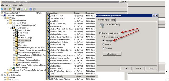 |
| Step 4 |
Apply the policy at the desired organizational unit or domain Active Directory level. The computers will receive the policy when they reboot and this service will be turned on. |
Configure Odyssey 5.X Supplicant for EAP-TLS Machine Authentications Against Active Directory
If you are using the Odyssey 5.x supplicant for EAP-TLS machine authentications against Active Directory, you must configure the following in the supplicant.
Procedure
| Step 1 |
Start Odyssey Access Client. |
| Step 2 |
Choose Odyssey Access Client Administrator from the Tools menu. |
| Step 3 |
Double-click the Machine Account icon. |
| Step 4 |
From the Machine Account page, you must configure a profile for EAP-TLS authentications: |
AnyConnect Agent for Machine Authentication
When you configure AnyConnect Agent for machine authentication, you can do one of the following:
-
Use the default machine hostname, which includes the prefix “host/.”
-
Configure a new profile, in which case you must include the prefix “host/” and then the machine name.
Active Directory Requirements to Support Easy Connect and Passive Identity services
Easy Connect and Passive Identity services use Active Directory login audit events generated by the Active Directory domain controller to gather user login information. The Active Directory server must be configured properly so the ISE user can connect and fetch the user login information. The following sections show how configure the Active Directory domain controller (configurations from the Active Directory side) to support Easy Connect and Passive Identity services.
In order to configure Active Directory domain controllers (configurations from the Active Directory side) to support Easy Connect and Passive Identity services use, follow these steps:
-
Set up Active Directory join points and domain controllers from ISE. See Add an Active Directory Join Point and Join Cisco ISE Node to the Join Point and Add Domain Controllers.
-
Configure WMI per domain controller. See Configure WMI for Passive ID.
-
Perform the following steps from Active Directory:
-
(Optional) Troubleshoot automatic configurations performed by ISE on Active Directory with these steps:
Configure Active Directory for Passive Identity service
ISE Easy Connect and Passive Identity services use Active Directory login audit events generated by the Active Directory domain controller to gather user login information. ISE connects to Active Directory and fetches the user login information.
The following steps should be performed from the Active Directory domain controller:
Procedure
| Step 1 |
Make sure relevant Microsoft patches are installed on the Active Directory domain controllers. |
|||||||||||||||||||||
| Step 2 |
Make sure the Active Directory logs the user login events in the Windows Security Log. Verify that the settings of the “Audit Policy” (part of the “Group Policy Management” settings) allows successful logons to generate the necessary events in the Windows Security Log (this is the default Windows setting, but you must explicitly ensure that this setting is correct). See Setting the Windows Audit Policy. |
|||||||||||||||||||||
| Step 3 |
You must have an Active Directory user with sufficient permissions for ISE to connect to the Active Directory. The following instructions show how to define permissions either for admin domain group user or none admin domain group user:
|
|||||||||||||||||||||
| Step 4 |
The Active Directory user used by ISE can be authenticated either by NT Lan Manager (NTLM) v1 or v2. You need to verify that the Active Directory NTLM settings are aligned with ISE NTLM settings to ensure successful authenticated connection between ISE and the Active Directory Domain Controller. The following table shows all Microsoft NTLM options, and which ISE NTLM actions are supported. If ISE is set to NTLMv2, all six options described in are supported. If ISE is set to support NTLMv1, only the first five options are supported.
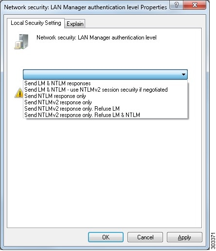 |
|||||||||||||||||||||
| Step 5 |
Make sure that you have created a firewall rule to allow traffic to dllhost.exe on Active Directory domain controllers. You can either turn the firewall off, or allow access on a specific IP (ISE IP address) to the following ports:
Higher ports are assigned dynamically or you can configure them manually. We recommend that you add %SystemRoot%\System32\dllhost.exe as a target. This program manages ports dynamically. All firewall rules can be assigned to specific IP (ISE IP). |
Set the Windows Audit Policy
Ensure that the Audit Policy (part of the Group Policy Management settings) allows successful logons. This is required to generate the necessary events in the Windows Security Log of the AD domain controller machine. This is the default Windows setting, but you must verify that this setting is correct.
Procedure
| Step 1 |
Choose . |
||
| Step 2 |
Navigate under Domains to the relevant domain and expand the navigation tree. |
||
| Step 3 |
Choose Default Domain Controller Policy, right click and choose Edit. The Group Policy Management Editor appears. |
||
| Step 4 |
Choose .
|
||
| Step 5 |
If any Audit
Policy item settings have been changed, you should then run
|
Set Permissions When AD User in the Domain Admin Group
For Windows 2008 R2,Windows 2012, and Windows 2012 R2, the Domain Admin group does not have full control on certain registry keys in the Windows operating system by default. The Active Directory admin must give the Active Directory user Full Control permissions on the following registry keys:
-
HKEY_CLASSES_ROOT\CLSID\{76A64158-CB41-11D1-8B02-00600806D9B6}
-
HKLM\Software\Classes\Wow6432Node\CLSID\{76A64158-CB41-11D1-8B02-00600806D9B6}
No registry changes are required for the following Active Directory versions:
-
Windows 2003
-
Windows 2003R2
-
Windows 2008
To grant full control, the Active Directory admin must first take ownership of the key, as shown below.
Procedure
| Step 1 |
Go to the Owner tab by right clicking the key. |
| Step 2 |
Click Permissions. |
| Step 3 |
Click Advanced. |
Required Permissions when AD User not in Domain Admin Group
For Windows 2012 R2, give the Active Directory user Full Control permissions on the following registry keys:
-
HKEY_CLASSES_ROOT\CLSID\{76A64158-CB41-11D1-8B02-00600806D9B6} -
HKLM\Software\Classes\Wow6432Node\CLSID\{76A64158-CB41-11D1-8B02-00600806D9B6}
The following permissions also are required when an Active Directory user is not in the Domain Admin group, but is in the Domain Users group:
-
Add Registry Keys to Allow ISE to Connect to the Domain Controller (see below)
These permissions are only required for the following Active Directory versions:
-
Windows 2003
-
Windows 2003R2
-
Windows 2008
-
Windows 2008 R2
-
Windows 2012
-
Windows 2012 R2
-
Windows 2016
Add Registry Keys to Allow ISE to Connect to the Domain Controller
You must manually add some registry keys to the domain controller to allow ISE to connect as a Domain User, and retrieve login authentication events. An agent is not required on the domain controllers or on any machine in the domain.
The following registry script shows the keys to add. You can copy and paste this into a text file, save the file with a .reg extension, and double click the file to make the registry changes. To add registry keys, the user must be an owner of the root key.
Windows Registry Editor Version 5.00

[HKEY_CLASSES_ROOT\CLSID\{76A64158-CB41-11D1-8B02-00600806D9B6}]
"AppID"="{76A64158-CB41-11D1-8B02-00600806D9B6}"

[HKEY_CLASSES_ROOT\AppID\{76A64158-CB41-11D1-8B02-00600806D9B6}]
"DllSurrogate"="  "

[HKEY_CLASSES_ROOT\Wow6432Node\AppID\{76A64158-CB41-11D1-8B02-00600806D9B6}]
"DllSurrogate"="  "
Make sure that you include two spaces in the value of the key DllSurrogate.
Keep the empty lines as shown in the script above, including an empty line at the end of the file.
Permissions to Use DCOM on the Domain Controller
The Active Directory user used for ISE Passive Identity services must have permissions to use DCOM (remote COM) on the Domain Controller. You can configure permissions with the dcomcnfg command line tool.
Procedure
| Step 1 |
Run the dcomcnfg tool from the command line. |
| Step 2 |
Expand Component Services. |
| Step 3 |
Expand . |
| Step 4 |
Select Action from the menu bar, click properties, and click COM Security. |
| Step 5 |
Make sure that the account that ISE will use for both Access and Launch has Allow permissions. That Active Directory user should be added to all the four options (Edit Limits and Edit Default for both Access Permissions and Launch and Activation Permissions). |
| Step 6 |
Allow all Local and Remote access for both Access Permissions and Launch and Activation Permissions. 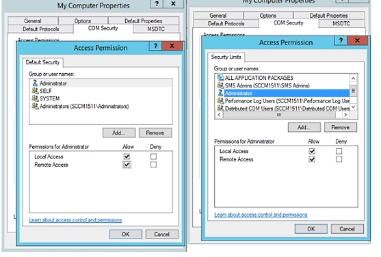 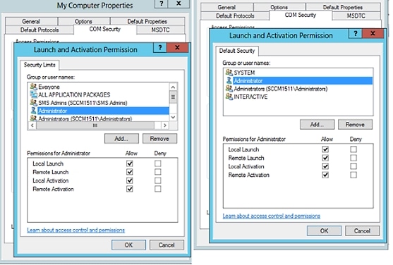 |
Set Permissions for Access to WMI Root/CIMv2 Name Space
By default, Active Directory users do not have permissions for the Execute Methods and Remote Enable. You can grant access using the wmimgmt.msc MMC console.
Procedure
| Step 1 |
Click Start
> Run and type
|
| Step 2 |
Right-click WMI Control and click Properties. |
| Step 3 |
Under the Security tab, expand Root and choose CIMV2. |
| Step 4 |
Click Security. |
| Step 5 |
Add the Active Directory user, and configure the required permissions as shown below. 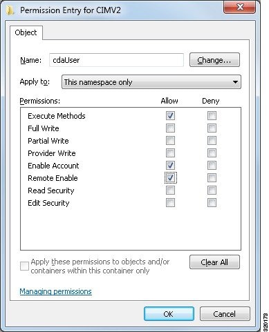 |
Grant Access to the Security Event Log on the AD Domain Controller
On Windows 2008 and later, you can grant access to the AD Domain controller logs by adding the ISE ID Mapping user to a group called Event Log Readers.
On all older versions of Windows, you must edit a registry key, as shown below.
Procedure
| Step 1 |
To delegate access to the Security event logs, find the SID for the account . |
| Step 2 |
Use the following command from the command line, also shown in the diagram below, to list all the SID accounts. You can also use the following command for a specific username and domain:  |
| Step 3 |
Find the SID, open the Registry Editor, and browse to the following location: |
| Step 4 |
Click on Security, and double click CustomSD. See Figure 2-7 For example, to allow read access to the ise_agent account 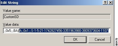 |
| Step 5 |
Restart the WMI service on the Domain Controller. You can restart the WMI services in the following two ways: |
Easy Connect
Easy Connect enables you to easily connect users from a wired endpoint to a network in a secure manner and monitor those users by authenticating them through an Active Directory Domain Controller and not by Cisco ISE. With Easy Connect, ISE collects user authentication information from the Active Directory Domain Controller. Because Easy Connect connects to a Windows system (Active Directory) using the MS WMI interface and queries logs from the Windows event messaging, it currently only supports Windows-installed endpoints. Easy Connect supports wired connections using MAB, which is much easier to configure than 802.1X. Unlike 802.1X, with Easy Connect and MAB:
-
You don't need to configure supplicants
-
You don't need to configure PKI
-
ISE issues a CoA after the external server (AD) authenticates the user
Easy Connect supports these modes of operation:
-
Enforcement-mode— ISE actively downloads the authorization policy to the network device for enforcement based on the user credentials.
-
Visibility-mode—ISE publishes session merge and accounting information received from the NAD device sensor in order to send that information to pxGrid.
In both cases, users authenticated with Active Directory (AD) are shown in the Cisco ISE live sessions view, and can be queried from the session directory using Cisco pxGrid interface by third-party applications. The known information is the user name, IP address, the AD DC host name and the AD DC NetBios name. For more information about pxGrid, see the pxGrid Node section in Cisco ISE Admin Guide: Deployment .
Once you have set up Easy Connect, you can then filter certain users, based on their name or IP address. For example, if you have an administrator from IT services who logs in to an endpoint in order to assist the regular user with that endpoint, you can filter out the administrator activity so it does not appear in Live Sessions, but rather only the regular user of that endpoint will appear. To filter passive identity services, see Filter Passive Identity Services.
Easy Connect Restrictions
-
MAC Authentication Bypass (MAB) supports Easy Connect. Both MAB and 802.1X can be configured on the same port, but you must have a different ISE policy for each service.
-
Only MAB connections are currently supported. You do not need a unique authentication policy for connections, because the connection is authorized and permissions are granted by an Easy Connect condition defined in the authorization policy.
-
Easy Connect is supported in High Availability mode. Multiple nodes can be defined and enabled with a Passive ID. ISE then automatically activates one PSN, while the other nodes remain in standby.
-
Only Cisco Network Access Devices (NADs) are supported.
-
IPv6 is not supported.
-
Wireless connections are not currently supported.
-
Only Kerberos auth events are tracked and therefore Easy Connect enables only user authentication and does not support machine authentication.
Easy Connect requires configuration in ISE, while the Active Directory Domain server must also have the correct patches and configuration based on instructions and guidelines issued by Microsoft. For information about configuring the Active Directory domain controller for ISE, see Active Directory Requirements to Support Easy Connect and Passive Identity services
Easy Connect Enforcement Mode
Easy Connect enables users to log on to a secure network from a wired endpoint (usually a PC) with a Windows operating system, by using MAC address bypass (MAB) protocol, and accessing Active Directory (AD) for authentication. ISE Easy Connect listens for a Windows Management Instrumentation (WMI) event from the Active Directory server for information about authenticated users. Once AD authenticates a user, the Domain Controller generates an event log that includes the user name and IP address allocated for the user. ISE receives notification of log in from AD, and then issues a RADIUS Change of Authorization (CoA).
Note |
MAC address lookup is not done for a MAB request when the Radius service-type is set to call-check. Therefore the return to the request is access-accept. This is the ISE default configuration. |
Easy Connect Enforcement Mode Process Flow
The Easy Connect Enforcement mode process is as follows:
-
The user connects to the NAD from a wired endpoint (such as a PC for example).
-
The NAD (which is configured for MAB) sends an access request to ISE. ISE responds with access, based on user configuration, allowing the user to access AD. Configuration must allow at least access to DNS, DHCP and AD.
-
The user logs in to the domain and a security audit event is sent to ISE.
-
ISE collects the MAC address from RADIUS and the IP address and domain name, as well as accounting information (login information) about the user, from the security audit event.
-
Once all data is collected and merged in the ISE session directory, ISE issues a CoA to the NAD (based on the appropriate policy managed in the policy service node (PSN)), and the user is provided access by the NAD to the network based on that policy.
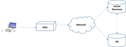
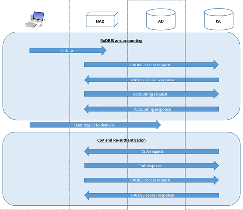
For more information about configuring Enforcement mode, see Configure Easy Connect Enforcement-Mode.
Easy Connect Visibility Mode
With the Visibility mode, ISE only monitors accounting information from RADIUS (part of the device sensor feature in the NAD) and does not perform authorization. Easy Connect listens for RADIUS Accounting and WMI events, and publishes that information to logs and reports, (and optionally, to pxGrid). Both RADIUS accounting start and session termination are published to pxGrid during user login using Active Directory when pxGrid is setup.
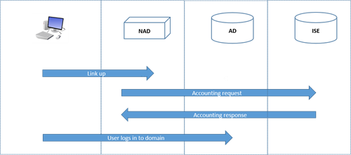
For more information about configuring Easy Connect Visibility mode, see Configure Easy Connect Visibility-Mode .
Configure Easy Connect Enforcement-Mode
Before you begin
-
For best performance, deploy a dedicated PSN to recieve WMI events.
-
Create a list of Active Directory Domain Controllers for the WMI node, which receives AD login events.
-
Determine the Microsoft Domain that ISE must join to fetch user groups from Active Directory.
-
Determine the Active Directory groups that are used as a reference in the authorization policy.
-
If you are using pxGrid to share session data from network devices with other pxGrid-enabled systems, then define a pxGrid persona in your deployment. For more information about pxGrid, see the pxGrid Node section in Cisco ISE Admin Guide: Deployment
-
After successful MAB, the NAD must provide a limited-access profile, which allows the user on that port access to the Active Directory server (as described in the overview).
Procedure
| Step 1 |
Enable the Passive Identity service on the dedicated Policy server (PSN) you intend to use for Easy Connect, so ISE can get group information and event information from Active Directory —Choose , open a node, and under General Settings, enable Enable Passive Identity Service.
|
||
| Step 2 |
Configure an Active Directory join point and domain controller to be used by Easy Connect. To do this, and for more information, see Active Directory Requirements to Support Easy Connect and Passive Identity services. |
||
| Step 3 |
Optionally, map AD domain controller groups in order to create different policies for different groups of users (for example, a different policy for Marketing employees versus Administration employees)—Choose , select the Active Directory to use, select the Groups tab, and add the Active Directory groups you plan to use in your authorization policies. The Active Directory groups that you map for the Domain Controller are
dynamically updated in the PassiveID dictionary and can then be used when you
set up your policy conditions rules.
|
||
| Step 4 |
Activate passive identity tracking—Choose . For any profiles to be used by Easy Connect, open the profile and enable Passive Identify Tracking.
|
||
| Step 5 |
Create policy rules—Choose , to create rules for Easy Connect. Click Add. Then define the condition:
|
||
| Step 6 |
Click Submit. |
Configure Easy Connect Visibility-Mode
Before you begin
-
For best performance, deploy a dedicated PSN to recieve WMI events.
-
Create a list of Active Directory Domain Controllers for the WMI node, which receives AD login events.
-
Determine the Microsoft Domain that ISE must join to fetch user groups from Active Directory.
-
If you are using pxGrid to share session data from network devices with other pxGrid-enabled systems, then define a pxGrid persona in your deployment. For more information about pxGrid, see the pxGrid Node section in Cisco ISE Admin Guide: Deployment
Procedure
| Step 1 |
Enable the Passive Identity service on the dedicated Policy server (PSN) you intend to use for Easy Connect, so ISE can get group information and event information from Active Directory —Choose , open a node, and under General Settings, enable Enable Passive Identity Service. |
| Step 2 |
Configure an Active Directory join point and domain controller to be used by Easy Connect. To do this, and for more information, see Active Directory Requirements to Support Easy Connect and Passive Identity services. |
PassiveID Work Center
Passive Identity Connector (the PassiveID work center) offers a centralized, one-stop installation and implementation enabling you to easily and simply configure your network in order to receive and share user identity information with a variety of different security product subscribers such as Cisco Firepower Management Center (FMC) and Stealthwatch. As the full broker for passive identification, the PassiveID work center collects user identities from different provider sources, such as Active Directory Domain Controllers (AD DC), maps the user login information to the relevant IP addresses in use and then shares that mapping information with any of the subscriber security products that you have configured.
What is Passive Identity?
Standard flows offered by Cisco Identity Services Engine (ISE), which provide an authentication, authorization and accounting (AAA) server, and utilize technologies such as 802.1X or Web Authentication, communicate directly with the user or endpoint, requesting access to the network, and then using their login credentials in order to verify and actively authenticate their identity.
Passive identity services do not authenticate users directly, but rather gather user identities and IP addresses from external authentication servers such as Active Directory, known as providers, and then share that information with subscribers. the PassiveID work center first receives the user identity information from the provider, usually based on the user login and password, and then performs the necessary checks and services in order to match the user identity with the relevant IP address, thereby delivering the authenticated IP address to the subscriber.
Passive Identity Connector (the PassiveID work center) Flow
The flow for the PassiveID work center is as follows:
-
Provider performs the authentication of the user or endpoint.
-
Provider sends authenticated user information to .
-
ISE normalizes, performs lookups, merges, parses and maps user information to IP addresses and publishes mapped details to pxGrid.
-
pxGrid subscribers receive the mapped user details.
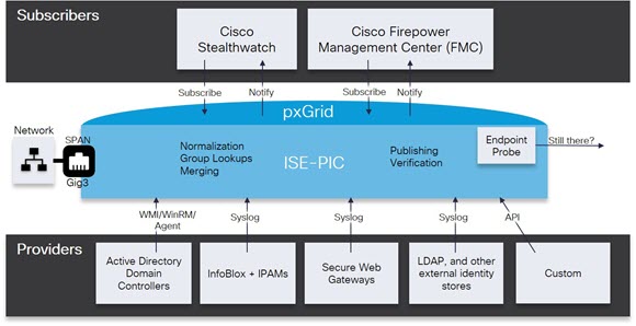
Initial Setup and Configuration
To get started using Cisco PassiveID work center quickly, follow this flow:
-
Ensure you have properly configured the DNS server, including configuring reverse lookup for the client machine from ISE. For more information, see DNS Server.
-
Enable the Passive Identity and pxGrid services on the dedicated Policy server (PSN) you intend to use for any of the Passive Identity services — Choose , open the relevant node, and under General Settings, enable Enable Passive Identity Service and pxGrid.
-
Synchronize clock settings for the NTP servers.
-
Configure an initial provider with the ISE Passive Identity Setup. For more information, see Getting Started with the PassiveID Setup
-
Configure a single or multiple subscribers. For more information, see Subscribers
After setting up an initial provider and subscriber, you can easily create additional providers (see the "Additional Passive Identity Service Providers" section in Cisco ISE Admin Guide: Asset Visibility) and manage your passive identification from the different providers in the PassiveID work center:
-
See the RADIUS Live Sessions section in Cisco ISE Admin Guide: Troubleshooting
-
See the Cisco ISE Alarms section in Cisco ISE Admin Guide: Troubleshooting
-
See the Reports section in Cisco ISE Admin Guide: Maintain and Monitor
-
See the TCP Dump Utility to Validate the Incoming Traffic section in Cisco ISE Admin Guide: Troubleshooting
PassiveID Work Center Dashboard
The Cisco PassiveID Work Center dashboard displays consolidated and correlated summary and statistical data that is essential for effective monitoring and troubleshooting, and is updated in real time. Dashlets show activity over the last 24 hours, unless otherwise noted. To access the dashboard, choose and then from the left panel choose Dashboard. You can only view the Cisco PassiveID Work Center Dashboard in the Primary Administration Node (PAN).
The Home page has two default dashboards that show a view of your PassiveID Work Center data:
-
Main—This view has a linear Metrics dashboard, chart dashlets, and list dashlets. In the PassiveID Work Center, the dashlets are not configurable. Available dashlets include:
-
Passive Identity Metrics—Passive Identity Metrics provides an overview of: the total number of unique live sessions currently being tracked, the total number of identity providers configured in the system, the total number of agents actively delivering identity data, and the total number of subscribers currently configured.
-
Providers—Providers provide user identity information to PassiveID Work Center. You configure the ISE probe (mechanisms that collect data from a given source) through which to receive information from the provider sources. For example, an Active Directory (AD) probe and an Agents probe both help ISE-PIC collect data from AD (each with different technology) while a Syslog probe collects data from a parser that reads syslog messages.
-
Subscribers—Subscribers connect to ISE to retrieve user identity information.
-
OS Types—The only OS type that can be displayed is Windows. Windows types display by Windows versions. Providers do not report the OS type, but ISE can query Active Directory to get that information. Up to 1000 entries are displayed in the dashlet. If you have more endpoints than that, or if you wish to display more OS types than Windows, you can upgrade to ISE.
-
Alarms—User identity-related alarms.
-
Active Directory as a Probe and a Provider
Active Directory (AD) is a highly secure and precise source from which to receive user identity information, including user name, IP address and domain name.
The AD probe, a Passive Identity service, collects user identity information from AD through WMI technology, while other probes use AD as a user identity provider through other technologies and methods. For more information about other probes and provider types offered by ISE, see the "Additional Passive Identity Service Providers" section in Cisco ISE Admin Guide: Asset Visibility.
By configuring the Active Directory probe you can also then quickly configure and enable these other probes (which also use Active Directory as their source):
-
Agent—Active Directory Agents
Note
The Active Directory agents are only supported on Windows Server 2008 and higher.
-
SPAN—SPAN
-
Endpoint probe—Endpoint Probe
In addition, configure the Active Directory probe in order to use AD user groups when collecting user information. You can use AD user groups for the AD, Agents, SPAN and Syslog probes. For more information about AD groups, see Configure Active Directory User Groups.
Set Up an Active Directory (WMI) Probe
To configure Active Directory and WMI for Passive Identity services you can use the Passive ID Work Center Wizard (see Getting Started with the PassiveID Setup) or you can follow the steps as follows (and see Active Directory Requirements to Support Easy Connect and Passive Identity services for additional information):
-
Configure the Active Directory probe. See Add an Active Directory Join Point and Join Cisco ISE Node to the Join Point.
-
Create a list of Active Directory Domain Controllers for the WMI-configured node (or nodes) that receives AD login events. See Add Domain Controllers.
-
Configure the Active Directory in order for it to integrate with ISE. See Configure WMI for Passive ID.
-
(Optional) Manage the Active Directory Provider.
Getting Started with the PassiveID Setup
Before you begin
-
Ensure the Microsoft Active Directory server does not reside behind a network address translator and does not have a Network Address Translation (NAT) address.
-
Ensure the Microsoft Active Directory account intended for the join operation is valid and is not configured with the Change Password on Next Login.
-
Ensure you have the privileges of a Super Admin or System Admin in ISE.
-
Enable the Passive Identity and pxGrid services on the dedicated Policy server (PSN) you intend to use for any of the Passive Identity services — Choose , open the relevant node, and under General Settings, enable Enable Passive Identity Service and pxGrid.
-
Ensure that ISE has an entry in the domain name server (DNS). Ensure you have properly configured reverse lookup for the client machine from ISE. For more information, see DNS Server
Procedure
| Step 1 |
Choose . From the Passive Identity Connector Overview screen, click Passive Identity Wizard. The PassiveID Setup opens: 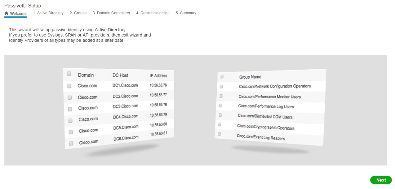 |
| Step 2 |
Click Next to begin the wizard. |
| Step 3 |
From the Active Directory step, enter a unique name that distinguishes this configured Active Directory join point quickly and easily in Join Point Name, from Active Directory domain enter the domain name for the Active Directory Domain to which this node is connected, and enter your Active Directory administrator user name and password. For more information about these and other Active Directory settings, see Active Directory Settings. It is strongly recommended that you choose Store credentials, in which case your administrator's user name and password will be saved in order to be used for all Domain Controllers (DC) that are configured
for monitoring.
|
| Step 4 |
Click Next to define Active Directory groups and check any user groups to be included and monitored. The Active Directory user groups automatically appear based on the Active Directory join point you configured in the previous
step.
|
| Step 5 |
Click Next again to move to the Domain Controllers step. From the Domain Controllers step, select the DCs to be monitored. If you choose Custom, then from the next screen select the specific DCs for monitoring. When finished, click Next. Once you have selected specific DCs, you have finished creating your first Active Directory provider and the summary screen
itemizes the DCs selected and their details.
|
| Step 6 |
Click Exit to complete the wizard. |
What to do next
When you finish configuring Active Directory as your initial provider, you can easily configure additional provider types as well. For more information, see the "Additional Passive Identity Service Providers" section in Cisco ISE Admin Guide: Asset Visibility. Furthermore, you can now also configure a subscriber, designated to receive the user identity information that is collected by any of the providers you have defined. For more information, see Subscribers.
Manage the Active Directory Provider
Once you have created and configured your Active Directory join points, continue to manage the Active Directory probe with these tasks:
Active Directory Settings
Active Directory (AD) is a highly secure and precise source from which to receive user information, including user name and IP address.
To create and manage Active Directory probes by creating and editing join points, choose , from the left panel choose Active Directory.
For more information, see Add an Active Directory Join Point and Join Cisco ISE Node to the Join Point.
| Field | Description |
|---|---|
|
Join Point Name |
A unique name that distinguishes this configured join point quickly and easily. |
|
Active Directory Domain |
The domain name for the Active Directory Domain to which this node is connected. |
|
Domain Administrator |
This is the user principal name or the user account name for the Active Directory user with administrator priveleges. |
|
Password |
This is the domain administrator's password as configured in Active Directory. |
|
Specifiy Organizational Unit |
Enter the administrator's organizational unit information |
|
Store Credentials |
It is strongly recommended that you choose Store credentials, in which case your administrator's user name and password will be saved in order to be used for all Domain Controllers (DC) that are configured
for monitoring.
For the Endpoint probe, you must choose Store credentials. |
| Field | Description |
|---|---|
|
ISE Node |
The URL for the specific node in the installation. |
|
ISE Node Role |
Indicates whether the node is the Primary or Secondary node in the installation. |
|
Status |
Indicates whether the node is actively joined to the Active Directory domain. |
|
Domain Controller |
For nodes that are joined to Active Directory, this column indicates the specific Domain Controller to which the node is connected in the Active Directory Domain. |
|
Site |
When an Active Directory forest is joined with ISE, this field indicates the specific Active Directory site within the forest as it appears in the Active Directory Sites & Services area. |
Choose .
| Field | Description |
|---|---|
|
Domain |
The fully qualified domain name of the server on which the domain controller is located. |
|
DC Host |
The host on which the domain controller is located. |
|
Site |
When an Active Directory forest is joined with ISE, this field indicates the specific Active Directory site within the forest as it appears in the Active Directory Sites & Services area. |
|
IP Address |
The IP address of the domain controller. |
|
Monitor Using |
Monitor Active Directory domain controllers for user identity information by one of these methods:
|
Choose . Click the link for the AD join point to be edited, go to the PassiveID tab and click Edit to edit an existing Domain Controller from the list.
| Field | Description |
|---|---|
|
Host FQDN |
Enter the fully qualified domain name of the server on which the domain controller is located. |
|
Description |
Enter a unique description for this domain controller in order to easily identiy it. |
|
User Name |
The administrator's user name for accessing Active Directory. |
|
Password |
The administrator's password for accessing Active Directory. |
|
Protocol |
Monitor Active Directory domain controllers for user identity information by one of these methods:
|
| Description |
|---|
|
Active Directory groups are defined and managed from Active Directory and the groups for the Active Directory that is joined to this node can be viewed from this tab. For more information about Active Directory, see https://msdn.microsoft.com/en-us/library/bb742437.aspx. |
| Field | Description |
|---|---|
|
History interval |
The time during which the Passive Identity service reads user login information that already occurred. This is required upon startup or restart of the Passive Identity service to catch up with events generated while it was unavailable. When the Endpoint probe is active, it maintains the frequency of this interval. |
|
User session aging time |
The amount of time the user can be logged in. The Passive Identity service identifies new user login events from the DC, however the DC does not report when the user logs off. The aging time enables Cisco ISE to determine the time interval for which the user is logged in. |
|
NTLM Protocol settings |
You can select either NTLMv1 or NTLMv2 as the communications protocol between Cisco ISE and the DC. NTLMv2 is the recommended default. |
Additional Passive Identity Service Providers
In order to enable ISE to provide identity information (Passive Identity Service ) to consumers that subscribe to the service (subscribers), you must first configure an ISE probe, which connects to the identity provider.
Providers that have been mapped and are actively delivering information to ISE can be viewed in the session directory, from the Live Sessions menu. For more information about Live Sessions, See the RADIUS Live Sessions section in Cisco ISE Admin Guide: Troubleshooting .
The table below provides details about all of the provider and probe types available from ISE, while the remainder of the chapter provides information regarding all types available except for Active Directory which is described in detail, in a dedicated chapter. For more information, see Active Directory as a Probe and a Provider.
You can define these provider types:
|
Provider Type (Probe) |
Description |
Source System (Provider) |
Technology |
User Identity Information Collected |
Document Link |
|
|---|---|---|---|---|---|---|
|
Active Directory (AD) |
A highly secure and precise source, as well as the most common, from which to receive user information. As a probe, AD works with WMI technology to deliver authenticated user identities. In addition, AD itself, rather than the probe, functions as a source system (a provider) from which other probes retrieve user data as well. |
Active Directory Domain Controller |
WMI |
|
||
|
Agents |
A native 32-bit application installed on Active Directory domain controllers or on member servers. The Agent probe is a quick and efficient solution when using Active Directory for user identity information. |
Agents installed on the domain controller or on a member server. |
|
|
||
|
Endpoint |
Always runs in the background in addition to other configured probes, in order to verify whether the user is still connected. |
WMI |
Whether the user is still connected |
|||
|
SPAN |
Sits on the network switch in order to listen to network traffic, and extract user identity information based on Active Directory data. |
SPAN, installed on the switch, and Kerberos messages |
|
SPAN | ||
| API providers |
Gather user identity information from any system programmed to communicate with a RESTful API client, using the RESTful API service offered by ISE. |
Any system programmed to communicate with a REST API client. |
RESTful APIs. User identity sent to subscribers in JSON format. |
|
||
| Syslog |
Parse syslog messages and retrieve user identities, including MAC addresses. |
|
Syslog messages |
|
Active Directory Agents
From the Passive Identity service work center install the native 32-bit application, Domain Controller (DC) agents, anywhere on the Active Directory (AD) domain controller (DC) or on a member server (based on your configurations) to retrieve user identity information from AD and then send those identities to the subscribers you have configured. The Agent probe is a quick and efficient solution when using Active Directory for user identity information. Agents can be installed on a separate domain, or on the AD domain, and once installed, they provide status updates to ISE once every minute.
The agents can be either automatically installed and configured by ISE, or you can manually install them. Upon installation, the following occurs:
-
The agent and its associated files are installed at the following path: Program Files/Cisco/Cisco ISE PassiveID Agent
-
A config file called PICAgent.exe.config is installed indicating the logging level for the agent. You can manually change the logging level from within the config file.
-
The CiscoISEPICAgent.log file is stored with all logging messages.
-
The nodes.txt file contains the list of all nodes in the deployment with which the agent can communicate. The agent contacts the first node in the list. If that node cannot be contacted, the agent continues to attempt communication according to the order of the nodes in the list. For manual installations, you must open the file and enter the node IP addresses. Once installed (manually or automatically), you can only change this file by manually updating it. Open the file and add, change or delete node IP addresses as necessary.
-
The Cisco ISE PassiveID Agent service runs on the machine, which you can manage from the Windows Services dialog box.
-
ISE supports up to 100 domain controllers, while each agent can monitor up to 10 domain controllers.
Note
In order to monitor 100 domain controllers, you must configure 10 agents.
Note |
The Active Directory agents are only supported on Windows Server 2008 and higher. If you cannot install agents, then use the Active Directory probe for passive identity services. For more information, see Active Directory as a Probe and a Provider. |
Automatically Install and Deploy Active Directory Agents
Before you begin
Before you begin:
-
Configure reverse lookup for the relevant DNS servers from the server side. For more information about the DNS server configuration requirements for ISE, see DNS Server
-
Ensure Microsoft .NET Framework is updated for the machine designated for the agents, to a minimum of version 4.0. For more information about the .NET framework, see https://www.microsoft.com/net/framework.
-
Active Passive ID and pxGrid services. For more information, see Initial Setup and Configuration.
-
Create an AD join point and add at least one domain controller. For more information about creating join points, see Active Directory as a Probe and a Provider.
Use AD user groups for the AD, Agents, SPAN and Syslog probes. For more information about AD groups, see Configure Active Directory User Groups.
Procedure
| Step 1 |
Choose and then choose Agents from the left panel to view all currently configured Domain Controller (DC) agents, to edit and delete existing agents, and to configure new agents. |
| Step 2 |
To add a new agent, click Add from the top of the table. To edit or change an existing client, checkmark the agent from the table and click Edit from the top of the table. |
| Step 3 |
To create the new agent and automatically install it on the host that you indicate in this configuration, select Deploy New Agent. |
| Step 4 |
Complete all mandatory fields in order to configure the client correctly. For more information, see Active Directory Agent Settings. |
| Step 5 |
Click Deploy. The agent
is automatically installed on the host according to the domain that you
indicated in the configuration, and the settings are saved. The agent now also
appears in the Agents table and can be applied to monitor specified domain
controllers, as described in the following steps.
|
| Step 6 |
Choose and then choose Active Directory from the left panel to view all currently configured join points. |
| Step 7 |
Click the link for the join point from which you would like to enable the agent you created. |
| Step 8 |
Choose the Passive ID tab in order to work with the domain controllers that you added as part of the prerequisites. |
| Step 9 |
Check mark the domain controller that you would like to monitor with the agent you created. and click Edit. |
| Step 10 |
From the dialog box that opens, ensure the mandatory fields are completed, from the Protocol dropdown select Agent, from the Agent field that appears, select the agent you created from the dropdown list, enter the user name and password credentials if you created any for the agent, and click Save. The agent
is enabled for the domain controller and the dialog box closes.
|
Manually Install and Deploy Active Directory Agents
Before you begin
Before you begin:
-
Configure reverse lookup for the relevant DNS servers from the server side. For more information about the DNS server configuration requirements for ISE, see DNS Server
-
Ensure Microsoft .NET Framework is updated for the machine designated for the agents, to a minimum of version 4.0. For more information about the .NET framework, see https://www.microsoft.com/net/framework.
-
Active Passive ID and pxGrid services. For more information, see Initial Setup and Configuration.
-
Create an AD join point and add at least one domain controller. For more information about creating join points, see Active Directory as a Probe and a Provider.
Use AD user groups for the AD, Agents, SPAN and Syslog probes. For more information about AD groups, see Configure Active Directory User Groups.
Procedure
| Step 1 |
Choose and then choose Agents from the left panel to view all currently configured Domain Controller (DC) agents, to edit and delete existing agents, and to configure new agents. |
| Step 2 |
Click Download Agent to download the picagent-installer.zip file for manual installation. The file is downloaded to your standard Windows Download folder.
|
| Step 3 |
Place the zip file on the designated host machine and run the installation. |
| Step 4 |
From the ISE GUI, again choose and then choose Agents from the left panel. |
| Step 5 |
To configure a new agent, click Add from the top of the table. To edit or change an existing client, checkmark the agent from the table and click Edit from the top of the table. |
| Step 6 |
To configure the agent that you have already installed on the host machine, select Register Existing Agent. |
| Step 7 |
Complete all mandatory fields in order to configure the client correctly. For more information, see Active Directory Agent Settings. |
| Step 8 |
Click Save. The agent settings are saved. The agent now also appears in the Agents table and can be applied to monitor specified domain
controllers, as described in the following steps.
|
| Step 9 |
Choose and then choose Active Directory from the left panel to view all currently configured join points. |
| Step 10 |
Click the link for the join point from which you would like to enable the agent you created. |
| Step 11 |
Choose the Passive ID tab in order to work with the domain controllers that you added as part of the prerequisites. |
| Step 12 |
Check mark the domain controller that you would like to monitor with the agent you created. and click Edit. |
| Step 13 |
From the dialog box that opens, ensure the mandatory fields are completed, from the Protocol dropdown select Agent, from the Agent field that appears, select the agent you created from the dropdown list, enter the user name and password credentials if you created any for the agent, and click Save. The agent is enabled for the domain controller and the dialog box closes.
|
Uninstall the Agent
Procedure
| Step 1 |
From the Windows dialog, go to Programs and Features. |
| Step 2 |
Find and select the Cisco ISE PassiveID Agent in the list of installed programs. |
| Step 3 |
Click Uninstall. |
Active Directory Agent Settings
Allow ISE to automatically install agents on a specified host in the network in order to retrieve user identity information from different Domain Controllers (DC) and deliver that information to Passive Identity service subscribers.
To create and manage agents, choose . See Automatically Install and Deploy Active Directory Agents.
View current agent statuses from the Agents table. Choose .
| Field | Description |
|---|---|
|
Name |
The agent name as you configured it. |
|
Host |
The fully qualified domain name of the host on which the agent is installed. |
|
Monitoring |
This is a comma separated list of domain controllers that the specified agent is monitoring. |
| Field | Description |
|---|---|
|
Deploy New Agent or Register Existing Agent |
|
|
Name |
Enter a name by which you can easily recognize the agent. |
|
Description |
Enter a description by which you can easily recognize the agent. |
|
Host FQDN |
This is the fully qualified domain name for the host on which the agent is installed (register existing agent), or is to be installed (automatic deployment). |
|
User Name |
Enter your user name in order to access the host on which to install the agent. Passive Identity service uses these credentials in order to install the agent for you. |
|
Password |
Enter your user password in order to access the host on which to install the agent. Passive Identity service uses these credentials in order to install the agent for you. |
API Providers
The API Providers feature in Cisco ISE enables you to push user identity information from your customized program or from the terminal server (TS)-Agent to the built-in ISE passive identity services REST API service. In this way, you can customize a programmable client from your network to send user identities that were collected from any network access control (NAC) system to the service. Furthermore, the Cisco ISE API provider enables you to interface with network applications such as the TS-Agent on a Citrix server, where all users have the same IP address but are assigned unique ports.
For example, an agent running on a Citrix server that provides identity mappings for users authenticated against an Active Directory (AD) server can send REST requests to ISE to add or delete a user session whenever a new user logs in or off. ISE then takes the user identity information, including the IP address and assigned ports, delivered from the client and sends it to pre-configured subscribers, such as the Cisco Firepower Management Center (FMC).
The ISE REST API framework implements the REST service over the HTTPS protocol (no client certificate validation necessary) and the user identity information is delivered in JSON (JavaScript Object Notation) format. For more information about JSON, see http://www.json.org/ .
The ISE REST API service parses user identities and in addition, maps that information to port ranges, in order to distinguish between the different users logged in simultaneously to one system. Everytime a port is allocated to a user, the API sends a message to ISE.
The REST API Provider Flow
Once you have configured a bridge to your customized client from ISE by declaring that client as a Provider for ISE and enabling that specific customized program (the client) to send RESTful requests, the ISE REST service works in the following way:
-
For client authentication, ISE requires an authentication token. A customized program on the client machine sends a request for an authentication token when initiating contact and then every time ISE notifies that the previous token has expired. The token is returned in response to the request, enabling ongoing communication between the client, and the ISE service.
-
Once a user has logged into the network, the client retrieves user identity information and posts that informaiton to the ISE REST service using the API Add command.
-
ISE receives and maps the user identity information.
-
ISE sends the mapped user identity information to the subscriber.
-
Whenever necessary, the customized machine can send a request to remove user information by sending a Remove API call and including the user ID received as the response when the Add call was sent.
Work with REST API Providers in ISE
Follow these steps to activate the REST service in ISE:
-
Configure the client side. For more information, see the client user documentation.
-
Activate Passive ID and pxGrid services. For more information, see Initial Setup and Configuration.
-
Ensure you have properly configured the DNS server, including configuring reverse lookup for the client machine from ISE. For more information about the DNS server configuration requirements for , see DNS Server
-
See Configure a Bridge to the ISE REST Service for Passive Identity Services.
Note
To configure the API Provider to work with a TS-Agent add the TS-Agent information when creating a bridge from ISE to that agent, and then consult with the TS-Agent documentation for information about sending API calls.
-
Generate an authentication token and send add and remove requests to the API service. .
Configure a Bridge to the ISE REST Service for Passive Identity Services
In order to enable the ISE REST API service to receive information from a specific client, you must first define the specific client from ISE. You can define multiple REST API clients with different IP addresses.
Before you begin
Before you begin:
-
Ensure you have activated Passive ID and pxGrid services. For more information, see Initial Setup and Configuration.
-
Ensure you have properly configured the DNS server, including configuring reverse lookup for the client machine from ISE. For more information about the DNS server configuration requirements for ISE, see DNS Server
Procedure
| Step 1 |
Choose and then choose API Providers from the left panel to view all currently configured clients, to edit and delete existing clients, and to configure new clients. The API
Providers table is displayed, including status information for each existing
client.
|
| Step 2 |
To add a new client, click Add from the top of the table. To edit or change an existing client, checkmark the client from the table and click Edit from the top of the table. |
| Step 3 |
Complete all mandatory fields in order to configure the client correctly. For more information, see API Provider Settings. |
| Step 4 |
Click Submit. The
client configuration is saved and the screen displays the updated API Providers
table. The client can now send posts to the
ISE REST service.
|
What to do next
Send API Calls to the Passive ID REST Service
Procedure
| Step 1 |
Enter the Cisco ISE URL in the address bar of your browser (for example, https://<ise hostname or ip address>/admin/) |
| Step 2 |
Enter the username and password that you specified and configured from the API Providers screen in the .ISE GUI. For more information, see Configure a Bridge to the ISE REST Service for Passive Identity Services. |
| Step 3 |
Press Enter. |
| Step 4 |
Enter the API call in the URL Address field of the target node as follows: |
| Step 5 |
Click Send to issue the API call. |
What to do next
API Provider Settings
Choose to configure a new REST API client for s.
Note |
The full API definition and object schemas can be retrieved with a request call as follows:
|
| Field | Description |
|---|---|
|
Name |
Enter a unique name for this client that distinguishes it quickly and easily from other clients. |
|
Description |
Enter a clear description of this client. |
|
Status |
Select Enabled to enable the client to interact with the REST services immediately upon completing configuration. |
|
Host/ IP |
Enter the IP address for the client host machine. Ensure you have properly configured the DNS server, including configuring reverse lookup for the client machine from ISE. |
|
User name |
Create a unique user name to be used when posting to the REST service. |
|
Password |
Create a unique password to be used when posting to the REST service. |
API Calls
Use these API calls to manage user identity events for Passive Identity services with Cisco ISE.
Purpose: Generate Authentication Token
-
Request
POST
https://<PIC IP address>:9094/api/fmi_platform/v1/identityauth/generatetoken
The request should contain the BasicAuth authorization header—provide the API provider's credentials as previously created from the ISE-PIC GUI. For more information see API Provider Settings.
-
Response Header
The header includes the X-auth-access-token. This is the token to be used when posting additional REST requests.
-
Response Body
HTTP 204 No Content
Purpose: Add User
-
Request
POST
https://<PIC IP address>:9094/api/identity/v1/identity/useridentity
Add X-auth-access-token in the header of the POST request. ( For example, Header: X-auth-access-token, Value: f3f25d81-3ac5-43ee-bbfb-20955643f6a7)
-
Response Header
201 Created
-
Response Body
{
"user": "<username>",
"srcPatRange": {
"userPatStart": <user PAT start value>,
"userPatEnd": <user PAT end value>,
"patRangeStart": <PAT range start value>
},
"srcIpAddress": "<src IP address>",
"agentInfo": "<Agent name>",
"timestamp": "<ISO_8601 format i.e. “YYYY-MM-DDTHH:MM:SSZ" >",
"domain": "<domain>"
}
-
Notes
-
srcPatRange can be removed in above json to create a single IP user binding.
-
Response body contains the "ID" which is the unique identifier for the user session binding created. Use this ID when sending a DELETE request to indicate which user should be removed.
-
This reponse also contains the self link which is the URL for this newly created user session binding.
-
Purpose: Remove User
-
Request
DELETE
https://<PIC IP address>:9094/api/identity/v1/identity/useridentity/<id>
In <id> enter the ID as was received from the Add response.
Add the X-auth-access-token in the header of the DELETE request. (For example, Header: X-auth-access-token, Value: f3f25d81-3ac5-43ee-bbfb-20955643f6a7)
-
Response Header
200 OK
-
Response Body
Response body contains the details about the user session binding which got deleted.
SPAN
SPAN is a Passive Identity service that allows you to quickly and easily enable ISE to listen to the network and retrieve user information without having to configure Active Directory to work directly with ISE. SPAN sniffs network traffic, specifically examining Kerberos messages, extracts user identity information also stored by Active Directory and sends that information to ISE. ISE then parses the information, ultimately delivering user name, IP address and domain name to the subscribers that you have also already configured from ISE.
In order for SPAN to listen to the network and extract Active Directory user information, ISE and Active Directory must both be connected to the same switch on the network. In this way, SPAN can copy and mirror all user identity data from Active Directory.
With SPAN, user information is retrieved in the following way:
-
The user endpoint, on the network, logs in.
-
Log in and user data are stored in Kerberos messages.
-
Once the user logs in and the user data passes through the switch, SPAN mirrors the network data.
-
ISE listens to the network for user information and retrieves the mirrored data from the switch.
-
ISE parses the user information and updates passive ID mappings.
-
ISE delivers the parsed user information to the subscribers.
Working with SPAN
Before you begin
In order to enable ISE to receive SPAN traffic from a network switch, you must first define which nodes and node interfaces are to listen to the switch. You can configure SPAN in order to listen to the different installed ISE nodes. For each node, only one interface can be configured to listen to the network and the interface used to listen must be dedicated to SPAN only.
Before you begin, ensure you have activated Passive ID and pxGrid services. Only nodes for which Passive ID has been turned on will appear in the list of available interfaces for configuring SPAN. For more information, see Initial Setup and Configuration.
In addition, you must:
-
Ensure Active Directory is configured on your network.
-
Run a CLI on the switch in the network that is also connected to Active Directory in order to ensure the switch can communicate with ISE.
-
Configure the switch to mirror the network from AD.
-
Configure a dedicated ISE network interface card (NIC) for SPAN. This NIC is used only for SPAN traffic.
-
Ensure the NIC that you have dedicated to SPAN is activated via the command line interface.
-
Create a VACL that sends only Kerberos traffic into the SPAN port.
Procedure
| Step 1 |
Choose and then choose SPAN from the left panel to configure SPAN. |
||
| Step 2 |
Enter a meaningful description (optional), select status Enabled, and choose the nodes and the relevant NICs that will be used to listen to the network switch. For more information, see SPAN Settings.
|
||
| Step 3 |
Click Save. The SPAN
configuration is saved and
ISE-PIC
ISE is now actively listening to network traffic.
|
SPAN Settings
From each node that you have deployed, quickly and easily configure ISE to receive user identities by installing SPAN on a client network.
| Field | Description | ||
|---|---|---|---|
|
Description |
Enter a unique description to remind you of which nodes and interfaces are currently enabled. |
||
|
Status |
Select Enabled to enable the client immediately upon completing configuration. |
||
|
Interface NIC |
Select one or more of the nodes installed for ISE, and then for each selected node, choose the node interface that is to listen to the network for information.
|
Syslog Providers
With the Syslog feature, the Passive Identity service parses syslog messages from any client (identity data provider) that delivers syslog messages, including regular syslog messages (from providers such as InfoBlox, Blue Coat, BlueCat, and Lucent) as well as DHCP syslog messages, and sends back user identity information, including MAC addresses. This mapped user identity data is then delivered to subscribers.
The Passive Identity service utilizes syslog messages received from a variety of providers once the administrator activates Passive ID and pxGrid services and configures the syslog client from the GUI. When configuring the provider, the administrator indicates the connection method (TCP or UDP) and the syslog template to be used for parsing.
Note |
When TCP is the configured connection type, if there is a problem with the message header and the host name cannot be parsed, then ISE attempts to match the IP address received in the packet to the IP address of any of the providers in the list of providers that have already been configured for Syslog messages in ISE. To view this list, choose . It is recommended that you check the message headers and customize if necessary in order to guarantee parsing succeeds. For more information about customizing headers, see Customize Syslog Headers. |
Once configured, the syslog probe sends syslog messages that are received to the ISE parser, which maps the user identity information, and publishes that information to ISE. ISE then delivers the parsed and mapped user identity information to the Passive Identity service subscribers.
Note |
DHCP syslog messages do not contain user names. Therefore, these messages are delivered from the parser with a delay so that ISE can first check users registered in the local session directory (displayed from Live Sessionss) and attempt to match those users by their IP addresses to the IP addresses listed in the DHCP syslog messages received, in order to correctly parse and deliver user identity information. If the data received from a DHCP syslog message cannot be matched to any of the currently logged in users, then the message is not parsed and user identity is not delivered. |
In order to parse syslog messages for user identity from ISE:
-
Configure syslog clients from which to receive user identity data—Configure Syslog Clients
-
Customize a single message header—Customize Syslog Headers
-
Customize message bodies by creating templates—Customize the Syslog Message Body.
-
Use the message templates pre-defined in ISE when configuring your syslog client as the message template used for parsing, or base your customized header or body templates on these pre-defined templates—Work with Syslog Pre-Defined Message Templates.
Configure Syslog Clients
In order to enable ISE to listen to syslog messages from a specific client, you must first define the specific client from ISE. You can define multiple providers with different IP addresses.
Before you begin
Before you begin, ensure you have activated Passive ID and pxGrid services. For more information, see Initial Setup and Configuration.
Procedure
| Step 1 |
Choose and then choose Syslog Providers from the left panel to view all currently configured clients, to edit and delete existing clients, and to configure new clients. The
Syslog Providers table is displayed, including status information for each
existing client.
|
| Step 2 |
To configure a new syslog client, click Add from the top of the table. To edit or change a previously configured client, checkmark the client from the table and click Edit from the top of the table. |
| Step 3 |
Complete all mandatory fields (see Syslog Settings for more details) and create a message template if necessary (see Customize the Syslog Message Body for more details) in order to configure the client correctly. |
| Step 4 |
Click Submit. The
client configuration is saved and the screen displays the updated Syslog
Providers table.
|
Syslog Settings
Configure ISE to receive user identities, including MAC addresses, by way of syslog messages from a specific client. You can define multiple providers with different IP addresses.
Choose , from the left panel choose Syslog Providers and from the table click Add to create a new syslog client.
| Field | Description | ||||
|---|---|---|---|---|---|
|
Name |
Enter a unique name that distinguishes this configured client quickly and easily. |
||||
|
Description |
A meaningful description of this Syslog provider. |
||||
|
Status |
Select Enabled to enable the client immediately upon completing configuration. |
||||
|
Host |
Enter the FQDN of the host machine. |
||||
|
Connection Type |
Enter UDP or TCP to indicate the channel by which ISE listens for syslog messages.
|
||||
|
Template |
A template indicates precise body message structure so that the parser can identify the pieces of information within the syslog message that should be parsed, mapped and delivered. For example, a template can indicate the exact position of the user name so that the parser can find the user name in every message received. From this field, indicate the template (for the body of the syslog message) to be used in order to recognize and correctly parse the syslog message. Choose either from the pre-defined dropdown list, or click New to create your own customized template. For more information about creating new templates, see Customize the Syslog Message Body. Most of the pre-defined templates use regular expressions, and customized templates should also use regular expressions.
ISE currently offers these pre-defined DHCP provider templates:
ISE offers these pre-defined regular syslog provider templates:
For information about templates, see Work with Syslog Pre-Defined Message Templates. |
||||
|
Default Domain |
If the domain is not identified in the syslog message for the specific user, this default domain is automatically assigned to the user in order to ensure that all users are assigned a domain. With the default domain or with the domain that was parsed from the message, the user name is appended to username@domain, thereby including that domain, in order to get more information about the user and user groups. |
Customize Syslog Message Structures (Templates)
A template indicates precise message structure so that the parser can identify the pieces of information within the syslog message that should be parsed, mapped and delivered. For example, a template can indicate the exact position of the user name so that the parser can find the user name in every message received. Templates determine the supported structures for both new and remove mapping messages.
Cisco ISE enables you to customize a single message header and multiple body structures, to be used by the Passive ID parser.
The templates should include regular expressions to define the structure for user name, IP address, MAC address and domain in order to enable the Passive ID parser to correctly identify whether the message is to add or remove user identity mapping and to correctly parse the user details.
When customizing your message templates, you can choose to base your customization on the message templates pre-defined in ISE-PIC ISE by consulting with the regular expressions and message structures used within those pre-defined options. For more information about the pre-defined template regular expressions, message structures, examples and more, see Work with Syslog Pre-Defined Message Templates.
You can customize:
-
A single message header—Customize Syslog Headers
-
Multiple message bodies—Customize the Syslog Message Body.
Note |
DHCP syslog messages do not contain user names. Therefore, these messages are delivered from the parser with a delay so that ISE-PIC ISE can first check users registered in the local session directory (displayed from Live Sessionss) and attempt to match those users by their IP addresses to the IP addresses listed in the DHCP syslog messages received, in order to correctly parse and deliver user identity information. If the data received from a DHCP syslog message cannot be matched to any of the currently logged in users, then the message is not parsed and user identity is not delivered. The delay necessary to properly match, parse and map details from DHCP messages cannot be applied to customized templates, and therefore it is not recommended that DHCP message templates be customized. Instead, use any of the pre-defined DHCP templates. |
Customize the Syslog Message Body
Cisco ISE enables you to customize your own syslog message templates (by customizing the message body) to be parsed by the Passive ID parser. The templates should include regular expressions to define the structure for user name, IP address, MAC address and domain.
Note |
DHCP syslog messages do not contain user names. Therefore, these messages are delivered from the parser with a delay so that ISE-PIC ISE can first check users registered in the local session directory (displayed from Live Sessionss) and attempt to match those users by their IP addresses to the IP addresses listed in the DHCP syslog messages received, in order to correctly parse and deliver user identity information. If the data received from a DHCP syslog message cannot be matched to any of the currently logged in users, then the message is not parsed and user identity is not delivered. The delay necessary to properly match, parse and map details from DHCP messages cannot be applied to customized templates, and therefore it is not recommended that DHCP message templates be customized. Instead, use any of the pre-defined DHCP templates. |
Create and edit syslog message body templates from within the syslog client configuration screen.
Note |
You can only edit your own customized templates. Pre-defined templates offered by the system cannot be changed. |
Procedure
| Step 1 |
Choose and then choose Syslog Providers from the left panel to view all currently configured clients, to edit and delete existing clients, and to configure new clients. The
Syslog Providers table is displayed, including status information for each
existing client.
|
| Step 2 |
Click Add to add a new syslog client or Edit to update an already configured client. If you only want to add or edit a template, it doesn't matter which of these options you select. For more information about configuring and updating syslog clients, see Configure Syslog Clients. |
| Step 3 |
From the Syslog Providers screen, next to the Template field, click New to create a new message template. To edit an existing template, select the template from the dropdown list and click Edit. The
Syslog
Template
screen opens.
|
| Step 4 |
Complete all mandatory fields. For information about how to enter the values correctly, see Syslog Customized Template Settings and Examples. |
| Step 5 |
Click Test to ensure the message is correctly parsed based on the strings you have entered. |
| Step 6 |
Click Save. The
customized template is saved and now appears in the dropdown list from the
Template field when configuring new and updating
existing syslog clients.
|
Customize Syslog Headers
Syslog headers, amongst other details, also contain the host name from which the message originated. If your syslog messages are not recognized by the ISE message parser, you may need to customize the message header by configuring the delimiter that proceeds the host name, thereby enabling ISE to recognize the host name and parse the message correctly. For more details about the fields in this screen, see Syslog Customized Template Settings and Examples. The customized header configuration is saved and added to the header types that are used by the parser whenever messages are received.
Note |
You can only customize a single header. Once you customize a header, when you click Custom Header, create a template to be stored and click Submit, the newest configuration is saved and overrides the previous customization. |
Procedure
| Step 1 |
Choose and then choose Syslog Providers from the left panel to view all currently configured clients, to edit and delete existing clients, and to configure new clients. The
Syslog Providers table is displayed, including status information for each
existing client.
|
||
| Step 2 |
Click Custom Header to open the Syslog Custom Header screen. |
||
| Step 3 |
From the Paste sample syslog enter an example of the header format in your syslog messages. For example, copy and paste this header from one of your messages: <181>Oct 10 15:14:08 Cisco.com. |
||
| Step 4 |
From the Separator field, indicate whether words are separated by spaces or tabs. |
||
| Step 5 |
From the Position of hostname in header field, indicate which place in the header is the host name. For example, in the header offered above, the host name is the fourth word in the header. Enter 4 to indicate this. The Hostname field displays the host name based on the details indicated in the first three fields. For example, if the header example in Paste sample syslog is as follows: <181>Oct 10 15:14:08 Cisco.com The separator is indicated as Space and the Position of hostname in header is entered as 4. The Hostname will automatically appear as Cisco.com, which is the fourth word in the header phrase pasted in the Paste sample syslog field. If the host name is incorrectly displayed, check the data you have entered in the Separator and Position of hostname in header fields. This example is as in the following screen capture: 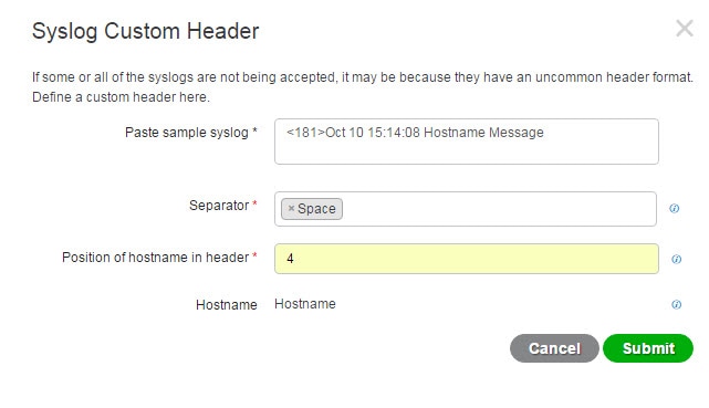 |
||
| Step 6 |
Click Submit.
The
customized header configuration is saved and added to the header types that are
used by the parser whenever messages are received.
|
Syslog Customized Template Settings and Examples
Cisco ISE enables you to customize your own syslog message templates to be parsed by the Passive ID parser. Customized templates determine the supported structures for both new and remove mapping messages. The templates should include regular expressions to define the structure for user name, IP address, MAC address and domain in order to enable the Passive ID parser to correctly identify whether the message is to add or remove user identity mapping and to correctly parse the user details.
Note |
Most of the pre-defined templates use regular expressions. Customized templates should also use regular expressions. |
Syslog Header Parts
You can customize a single header that is recognized by the Syslog probe by configuring the delimiter that proceeds the host name.
Choose , from the left panel choose Syslog Providers and from the table click Custom Header to create a customized syslog message header.
The following table describes the different parts and fields that can be included in your customized syslog header. For more information about regular expressions, see Table 3.
| Field | Description |
|---|---|
|
Paste sample syslog |
Enter an example of the header format in your syslog messages. For example, copy and paste this header: <181>Oct 10 15:14:08 Hostname Message |
|
Separator |
Indicate whether words are separated by spaces or tabs. |
|
Position of hostname in header |
Indicate which place in the header is the host name. For example, in the header offered above, the host name is the fourth word in the header. Enter 4 to indicate this. |
|
Hostname |
Displays the hostname based on the details indicated in the first three fields. For example, if the header example in Paste sample syslog is as follows: <181>Oct 10 15:14:08 Hostname Message The separator is indicated as Space and the Position of hostname in header is entered as 4. The Hostname will automatically appear as Hostname. If the host name is incorrectly displayed, check the data you have entered in the Separator and Position of hostname in header fields. |
Syslog Template Parts and Descriptions for the Message Body
The following table describes the different parts and fields that can be included in your customized syslog message templates. For more information about regular expressions, see Table 3.
|
Part |
Field |
Description |
|---|---|---|
|
Name |
A unique name by which to recognize the purpose of this template. |
|
|
Mapping Operations |
New Mapping |
A regular expression that describes the kind of mapping used with this template to add a new user. For example, enter "logged on from" in this field to indicate a new user that has logged on to the F5 VPN. |
|
Removed Mapping |
A regular expression that describes the kind of mapping used with this template to remove a user. For example, enter "session disconnect" in this field to indicate a user that should be removed for ASA VPN. |
|
|
User Data |
IP Address |
A regular expression that indicates the IP addresses to be captured. For example, for Bluecat messages, to capture identities for users within this IP address range, enter: (on\s|to\s)((?:(?:25[0-5]|2[0-4][0-9]|[01]?[0-9][0-9]?)\.){3}(?:25[0-5]|2[0-4][0-9]|[01]?[0-9][0-9]?)) |
|
User Name |
A regular expression that indicates the user name format to be captured. |
|
|
Domain |
A regular expression that indicates the domain to be captured. |
|
|
Mac Address |
A regular expression that indicates the MAC address format to be captured. |
Regular Expression Examples
In order to parse messages use regular expressions. This sections offers regular expression examples in order to parse IP address, user name and add mapping messages.
For example, use regular expressions to parse the following messages:
<174>192.168.0.1 %ASA-4-722051: Group <DfltGrpPolicy> User <user1> IP <192.168.0.10> IPv4 Address <192.168.0.6> IPv6 address <::> assigned to session
<174>192.168.0.1 %ASA-6-713228: Group = xyz, Username = user1, IP = 192.168.0.12, Assigned private IP address 192.168.0.8 to remote user
The regular expressions are as defined in the following table.
|
Part |
Regular Expression |
|---|---|
|
IP address |
Address <([^\s]+)>|address ([^\s]+) |
|
User name |
User <([^\s]+)>| Username = ([^\s]+) |
|
Add mapping message |
(%ASA-4-722051|%ASA-6-713228) |
Work with Syslog Pre-Defined Message Templates
Syslog messages have a standard structure which include a header and the message body.
The pre-defined templates offered by Cisco ISE are described in this section, including content details for the headers that are supported, as well as the supported body structure, based on the origin of the messages.
In addition, you can create your own templates with customized body content for sources that are not pre-defined in the system. The supported structure for customized templates is also described in this section. You can configure a single customized header to be used in addition to the headers pre-defined in the system, when parsing messages, and you can configure multiple customized templates for the message body. For more information about customizing the header, see Customize Syslog Headers. For more information about customizing the body, see Customize the Syslog Message Body.
Note |
Most of the pre-defined templates use regular expressions, and customized templates should also use regular expressions. |
Message Headers
There are two header types recognized by the parser, for all message types (new and remove), for all client machines. These headers are as follows:
-
<171>Host message
-
<171>Oct 10 15:14:08 Host message
Once received, the header is parsed for host name, which can be IP address, hostname, or full FQDN.
Headers can also be customized. To customize your headers, see Customize Syslog Headers.
Syslog ASA VPN Pre-Defined Template
The supported syslog message format and types for ASA VPN are as described below.
Headers
Headers supported by the parser are identical for all clients, as described in Work with Syslog Pre-Defined Message Templates.
New Mapping Body Messages
There are different ASA VPN body messages that are recognized by the parser as described in the following table.
| Body Message |
Parsing Example |
||
|---|---|---|---|
|
%ASA-6-109005 Authentication succeeded for user UserA from 10.0.0.11/100 to 10.10.11.11/20 on interface eth1/1 |
[UserA,10.0.0.11] |
||
|
%ASA-6-602303 IPSEC: An direction tunnel_type SA (SPI=spi) between local_IP and 10.0.0.11 (UserA) has been created. |
|||
|
%ASA-6-721016 (device) WebVPN session for client user UserA, IP 10.0.0.11 has been created. |
|||
|
%ASA-6-603104 PPTP Tunnel created, tunnel_id is number, remote_peer_ip is remote_address, ppp_virtual_interface_id is number,\ client_dynamic_ip is 10.0.0.11,ffg123 #% UserA is UserA, MPPE_key_strength is string |
|||
|
%ASA-6-603106 L2TP Tunnel created, tunnel_id is number, remote_peer_ip is remote_address, ppp_virtual_interface_id is number,\ client_dynamic_ip is 10.0.0.11, UserA is user |
|||
|
%ASA-6-113039 Group group User UserA IP 10.0.0.11 AnyConnect parent session started. |
|||
|
%ASA-6-802001 User UserA IP 10.100.1.1 OS os_name UDID number MDM action session started. |
|||
|
%ASA-6-713228: Group = xyz, UserA = xxxx227, IP = 192.168.0.11, Assigned private IP address 172.16.0.11 to remote user |
[UserA,172.16.0.11]
|
||
|
%ASA-4-722051: Group <DfltGrpPolicy> User <UserA> IP <172.16.0.12> IPv4 Address <172.16.0.21> IPv6 address <::> assigned to session |
[UserA,172.16.0.12]
|
Remove Mapping Body Messages
The Remove Mapping messages supported for ASA VPN by the parser are as described in this section.
Once received, the body is parsed for user details as follows:
[UserA,10.1.1.1]
| Body Message |
|---|
|
%ASA-4-113019 Group = group, UserA = UserA, IP = 10.1.1.1, Session disconnected. Session Type: type, Duration:\ duration, Bytes xmt: count,Bytes rcv: count, Reason: reason |
|
%ASA-4-717052 Group group name User UserA IP 10.1.1.1 Session disconnected due to periodic certificate authentication failure. Subject Name id subject name Issuer Name id issuer name\ Serial Number id serial number |
|
%ASA-6-602304 IPSEC: An direction tunnel_type SA (SPI=spi) between local_IP and 10.1.1.1 (UserA) has been deleted. |
|
%ASA-6-721018 WebVPN session for client user UserA, IP 10.1.1.1 has been deleted. |
|
%ASA-4-722049 Group group User UserA IP 10.1.1.1 Session terminated: SVC not enabled or invalid image on the ASA |
|
%ASA-4-722050 Group group User UserA IP 10.1.1.1 Session terminated: SVC not enabled for the user. |
|
%ASA-6-802002 User UserA IP 10.1.1.1 OS os_name UDID number MDM action session terminated. |
|
%ASA-3-716057 Group group User UserA IP 10.1.1.1 Session terminated, no type license available. |
|
%ASA-3-722046 Group group User UserA IP 10.1.1.1 Session terminated: unable to establish tunnel. |
|
%ASA-4-113035 Group group User UserA IP 10.1.1.1 Session terminated: AnyConnect not enabled or invalid AnyConnect image on the ASA. |
|
%ASA-4-716052 Group group-name User UserA IP 10.1.1.1 Pending session terminated. |
|
%ASA-6-721018 WebVPN session for client user UserA, IP 10.1.1.1 has been deleted. |
Syslog Bluecat Pre-Defined Template
The supported syslog message format and types for Bluecat are as described below.
Headers
Headers supported by the parser are identical for all clients, as described in Work with Syslog Pre-Defined Message Templates.
New Mapping Body Messages
The messages supported for New Mapping for Bluecat syslog are as described in this section.
Once received, the body is parsed for user details as follows:
[macAddress=nn:xx:nn:ca:xx:nn,ip=172.16.0.12]
| Body |
|---|
| Nov 7 23:37:32 xx-campus1 dhcpd: DHCPACK on 172.16.0.13 to nn:xx:nn:ca:xx:nn via 172.16.0.17 |
Remove Mapping Messages
There are no remove mapping messages known for Bluecat.
Syslog F5 VPN Pre-Defined Template
The supported syslog message format and types for F5 VPN are as described below.
Headers
Headers supported by the parser are identical for all clients, as described in Work with Syslog Pre-Defined Message Templates.
New Mapping Body Messages
There are different F5 VPN body messages that are recognized by the parser as described in the following table.
Once received, the body is parsed for user details as follows:
[user=UserA,ip=172.16.0.12]
| Body |
|---|
| Apr 10 09:33:58 Oct 2 08:28:32 abc.xyz.org security[nnnnn]: [UserA@vendor-abcr] User UserA logged on from 172.16.0.21 to \ 172.16.0.12 Sid = xyz\ |
Remove Mapping Messages
Currently there are no remove messages for F5 VPN that are supported.
Syslog Infoblox Pre-Defined Template
The supported syslog message format and types for Infoblox are as described below.
Headers
Headers supported by the parser are identical for all clients, as described in Work with Syslog Pre-Defined Message Templates.
New Mapping Body Messages
There are different ASA VPN body messages that are recognized by the parser as described in the following table.
Once received, the body is parsed for user details as follows:
[macAddress= nn:xx:xx:xx:nn:nn,ip=10.0.10.100]
| Body Message |
|---|
|
Nov 15 11:37:26 user1-lnx dhcpd[3179]: DHCPACK on 10.0.0.14 to nn:xx:xx:nx:nn:nn (android-df67ddcbb1271593) via eth2 relay 10.0.0.24 lease-duration 3600 |
|
Nov 15 11:38:11 user1-lnx dhcpd[3179]: DHCPACK on 172.16.0.18 to nn:xx:xx:xn:nn:nn (DESKTOP-HUDGAAQ) via eth2 relay 172.16.0.13 lease-duration 691200 (RENEW) |
|
Nov 15 11:38:11 192.168.0.12 dhcpd[25595]: DHCPACK to 10.0.0.11 (nn:xx:xx:xn:nn:nx) via eth1 |
Remove Mapping Messages
The following messages are supported for Remove Mapping.
There are several body messages recognized by the parser for remove mapping messages, as described in the table below.
Once received, the body is parsed for user details as follows:
-
If MAC address is included:
[00:0c:29:a2:18:34,10.0.10.100]
-
If MAC address is not included:
[10.0.10.100]
| Body Message |
|---|
|
07-11-2016 23:37:32 Daemon.Info 10.0.10.2 Jul 12 10:42:26 10.0.10.2 dhcpd[26083]: DHCPEXPIRE 10.0.10.100 has expired |
|
07-11-2016 23:37:32 Daemon.Info 10.0.10.2 Jul 12 10:42:26 10.0.10.2 dhcpd[26083]: DHCPRELEASE of 10.0.10.100 from 00:0c:29:a2:18:34 \ (win10) via eth1 uid 01:00:0c:29:a2:18:34 |
|
07-11-2016 23:37:32 Daemon.Info 10.0.10.2 Jul 12 10:42:26 10.0.10.2 dhcpd[25595]: RELEASE on 10.20.31.172 to c0:ce:cd:44:4f:bd |
Syslog Linux DHCPd3 Pre-Defined Template
The supported syslog message format and types for Linux DHCPd3 are as described below.
Headers
Headers supported by the parser are identical for all clients, as described in Work with Syslog Pre-Defined Message Templates.
New Mapping Messages
There are different Linux DHCPd3 body messages that are recognized by the parser as described in the following table.
Once received, the body is parsed for user details as follows:
[macAddress=24:ab:81:ca:f2:72,ip=172.16.0.21]
| Body Message |
|---|
|
Nov 11 23:37:32 dhcpsrv dhcpd: DHCPACK on 10.0.10.100 to 00:0c:29:a2:18:34 (win10) via eth1 |
|
Nov 11 23:37:32 dhcpsrv dhcpd: DHCPACK on 10.0.10.100 (00:0c:29:a2:18:34) via eth1 |
Remove Mapping Body Messages
The Remove Mapping messages supported for Linux DHCPd3 by the parser are as described in this section.
Once received, the body is parsed for user details as follows:
[00:0c:29:a2:18:34 ,10.0.10.100]
| Body Message |
|---|
|
Nov 11 23:37:32 dhcpsrv dhcpd: DHCPEXPIRE 10.0.10.100 has expired |
|
Nov 11 23:37:32 dhcpsrv dhcpd: DHCPRELEASE of 10.0.10.100 from 00:0c:29:a2:18:34 (win10) via eth1 |
Syslog MS DHCP Pre-Defined Template
The supported syslog message format and types for MS DHCP are as described below.
Headers
Headers supported by the parser are identical for all clients, as described in Work with Syslog Pre-Defined Message Templates.
New Mapping Body Messages
There are different MS DHCP body messages that are recognized by the parser as described in the following table.
Once received, the parser divides data by searching for the comma (,) and then messages of these formats are parsed as in the following example:
[macAddress=000C29912E5D,ip=10.0.10.123]
| Body Message |
|---|
|
Nov 11 23:37:32 10,07/21/16,16:55:22,Assign,10.0.10.123,win10.IDCSPAN.Local,000C29912E5D,,724476048,0,,,,0x4D53465420352E30,MSFT,5.0 |
Remove Mapping Body Messages
The Remove Mapping messages supported for MS DHCP by the parser are as described in this section.
Once received, the parser divides data by searching for the comma (,) and then messages of these formats are parsed as in the following example:
[macAddress=000C29912E5D,ip=10.0.10.123]
| Body Message |
|---|
|
Nov 11 23:37:32 12,07/21/16,16:55:18,Release,10.0.10.123,win10.IDCSPAN.Local,000C29912E5D,,3128563632,\ 0,,,,,,,,,0 |
Syslog SafeConnect NAC Pre-Defined Template
The supported syslog message format and types for SafeConnect NAC are as described below.
Headers
Headers supported by the parser are identical for all clients, as described in Work with Syslog Pre-Defined Message Templates.
New Mapping Body Messages
There are different SafeConnect NAC body messages that are recognized by the parser as described in the following table.
Once received, the body is parsed for user details as follows:
[user=galindk1i,p=xxxx.xx.xxx.xxd,domain=Resnet-Macs]
| Body Message |
|---|
|
Apr 10 09:33:58 nac Safe*Connect: authenticationResult|xxx.xx.xxx.xxx|xxx.xx.xxx.xxx|UserA|true|Resnet-Macs|TCNJ-Chain|001b63b79018|MAC |
Remove Mapping Messages
Currently there are no remove messages for Safe Connect that are supported.
Syslog Aerohive Pre-Defined Templates
The supported syslog message format and types for Aerohive are as described below.
Headers
Headers supported by the parser are identical for all clients, as described in Work with Syslog Pre-Defined Message Templates.
New Mapping Body Messages
There are different Aerohive body messages that are recognized by the parser as described in the following table.
Details parsed from the body include user name and IP address. The regular expression used for parsing is as in the following examples:
-
New mapping—auth\: -
IP—ip ([A-F0-9a-f:.]+) -
User name—UserA ([a-zA-Z0-9\_]+)
Once received, the body is parsed for user details as follows:
[UserA,10.5.50.52]
| Body Message |
|---|
|
2013-04-01 14:06:05 info ah auth: Station 1cab:a7e6:cf7f ip 10.5.50.52 UserA UserA |
Remove Mapping Messages
Currently the system does not support remove mapping messages from Aerohive.
Syslog Blue Coat Pre-Defined Templates—Main Proxy, Proxy SG, Squid Web Proxy
The system supports the following message types for Blue Coat:
-
BlueCoat Main Proxy
-
BlueCoat Proxy SG
-
BlueCoat Squid Web Proxy
The supported syslog message format and types for Bluecoat messages are as described below.
Headers
Headers supported by the parser are identical for all clients, as described in Work with Syslog Pre-Defined Message Templates.
New Mapping Body Messages
There are different Blue Coat body messages that are recognized by the parser as described in the following table.
Once received, the body is parsed for user details as follows:
[UserA,192.168.10.24]
| Body Message (this example is taken from a BlueCoat Proxy SG message) |
|---|
|
2016-09-21 23:05:33 58 10.0.0.1 UserA - - PROXIED "none" http://www.example.com/ 200 TCP_MISS GET application/json;charset=UTF-8 http site.api.example.com 80 /apis/v2/scoreboard/header ?rand=1474499133503 - "Mozilla/5.0 (Windows NT 10.0; Win64; x64) AppleWebKit/537.36 (KHTML, like Gecko) Chrome/46.0.2486.0 Safari/537.36 Edge/13.10586" 192.168.10.24 7186 708 - "unavailable |
The following table describes the different regular expression structures used per client for new mapping messages.
| Client |
Regular expressions |
|---|---|
|
BlueCoat Main Proxy |
New mapping (TCP_HIT|TCP_MEM){1} IP \s((?:(?:[0-9]{1,3}\.){3}[0-9]{1,3})|(?:(?:[a-zA-Z0-9]{1,4}\:{1,2}){1,7}[a-zA-Z0-9]{1,4}))\s User name \s\-\s([a-zA-Z0-9\_]+)\s\-\s |
|
BlueCoat Proxy SG |
New mapping (\-\sPROXIED){1} IP \s((?:(?:[0-9]{1,3}\.){3}[0-9]{1,3})|(?:(?:[a-zA-Z0-9]{1,4}\:{1,2}){1,7}[a-zA-Z0-9]{1,4}))\s[a-zA-Z0-9\_]+\s\- User name \s[0-9]{1,3}\.[0-9]{1,3}\.[0-9]{1,3}\.[0-9]{1,3}\s([a-zA-Z0-9\_]+)\s\- |
|
BlueCoat Squid Web Proxy |
New mapping (TCP_HIT|TCP_MEM){1} IP \s((?:(?:[0-9]{1,3}\.){3}[0-9]{1,3})|(?:(?:[a-zA-Z0-9]{1,4}\:{1,2}){1,7}[a-zA-Z0-9]{1,4}))\sTCP User name \s([a-zA-Z0-9\._]+)\s\-\/ |
Remove Mapping Messages
Remove mapping messages are supported for Blue Coat clients, though no examples are currently available.
The following table describes the different known regular expression structure examples used per client for remove mapping messages.
| Client |
Regular expressions |
|---|---|
|
BlueCoat Main Proxy |
(TCP_MISS|TCP_NC_MISS){1} |
|
BlueCoat Proxy SG |
No example currently available. |
|
BlueCoat Squid Web Proxy |
(TCP_MISS|TCP_NC_MISS){1} |
Syslog ISE and ACS Pre-Defined Templates
When listening to ISE or ACS clients, the parser receives the following message types:
-
Pass authentication—when the user is authenticated by ISE or ACS, the pass authentication message is issued notifying that authentication succeeded, and including user details. The message is parsed and the user details and session ID are saved from this message.
-
Accounting start and accounting update messages (new mapping)—received from ISE or ACS, the accounting start or accounting update message is parsed with the user details and session ID that were saved from the Pass Authentication message and then the user is mapped.
-
Accounting stop (remove mapping)—when received from ISE or ACS, the user mapping is deleted from the system.
The supported syslog message format and types for ISE and ACS are as described below.
Pass Authentication Messages
The following messages are supported for Pass Authentication.
-
Header
<181>Sep 13 10:51:41 Server logTag messageId totalFragments currentFragments messageFor example: <181>Sep 13 10:51:41 Positron CISE_PassiveID 0000005255 1 0 message
-
Body
Passed-Authentication 000011 1 0 2016-05-09 12:48:11.011 +03:00 0000012435 5200 NOTICE Passed-Authentication: Authentication succeeded, ConfigVersionId=104, Device IP Address=10.0.0.12, DestinationIPAddress=10.0.0.18, DestinationPort=1812, UserA=UserA, Protocol=Radius, RequestLatency=45, NetworkDeviceName=DefaultNetworkDevice, User-Name=UserA, NAS-IP-Address=1.1.1.1, Session-Timeout=90, Calling-Station-ID=, cisco-av-pair=audit-session-id=5
-
Parsing Example
User name and session ID only are parsed.
[UserA,5]
Accounting Start/Update (New Mapping) Messages
The following messages are supported for New Mapping.
-
Header
<181>Sep 13 10:51:41 Server logTag messageId totalFragments currentFragments messageFor example: <181>Sep 13 10:51:41 Positron CISE_PassiveID 0000005255 1 0 message
-
Body
CISE_RADIUS_Accounting 000011 1 0 2016-05-09 12:53:52.823 +03:00 0000012451 3000 NOTICE Radius-Accounting: RADIUS Accounting start request, ConfigVersionId=104, Device IP Address=10.0.0.12, RequestLatency=12, NetworkDeviceName=DefaultNetworkDevice, User-Name=UserA, NAS-IP-Address=10.0.0.1, Framed-IP-Address=10.0.0.16, Session-Timeout=90, Calling-Station-ID=, Acct-Status-Type=Start, Acct-Session-Id=6, cisco-av-pair=audit-session-id=5
-
Parsing Example
Parsed details include user name, and framed IP address, as well as the MAC address if it is included in the message.
[UserA,10.0.0.16]
Remove Mapping Messages
The following messages are supported for Remove Mapping.
-
Header
<181>Sep 13 10:51:41 Server logTag messageId totalFragments currentFragments messageFor example: <181>Sep 13 10:51:41 Positron CISE_PassiveID 0000005255 1 0 message
-
Body
2016-05-09 12:56:27.274 +03:00 0000012482 3001 NOTICE Radius-Accounting: RADIUS Accounting stop request, ConfigVersionId=104, Device IP Address=10.0.0.17, RequestLatency=13, NetworkDeviceName=DefaultNetworkDevice, User-Name=UserA, NAS-IP-Address=10.0.0.1, Framed-IP-Address=10.0.0.16, Session-Timeout=90, Calling-Station-ID=, Acct-Status-Type=Stop, Acct-Session-Id=104, cisco-av-pair=audit-session-id=5
-
Parsing Example
Parsed details include user name, and framed IP address, as well as the MAC address if it is included in the message.
[UserA,10.0.0.16]
Syslog Lucent QIP Pre-Defined Template
The supported syslog message format and types for Lucent QIP are as described below.
Headers
Headers supported by the parser are identical for all clients, as described in Work with Syslog Pre-Defined Message Templates.
New Mapping Body Messages
There are different Lucent QIP body messages that are recognized by the parser as described in the following table.
The regular expression structure for these messages is as follows:
DHCP_GrantLease|:DHCP_RenewLease
Once received, the body is parsed for user details as follows:
[00:0C:29:91:2E:5D,10.0.0.11]
| Body Message |
|---|
|
DHCP:subtype=0:Single:$IGNORE_N$ DHCP_GrantLease: Host=$HOSTNAME$ P=10.0.0.11 MAC= 00:0C:29:91:2E:5D |
|
DHCP:subtype=0:Single:$IGNORE_N$ DHCP_RenewLease: Host=$HOSTNAME$ P=10.0.0.11 MAC= 00:0C:29:91:2E:5D |
Remove Mapping Body Messages
There are different Lucent QIP body messages that are recognized by the parser as described in the following table.
The regular expression structure for these messages is as follows:
Delete Lease:|DHCP Auto Release:
Once received, the body is parsed for user details as follows:
[10.0.0.11]
| Body Message |
|---|
|
DHCP:subtype=0:Single:$IGNORE_N$ Delete Lease: IP=10.0.0.11 $IGNORE_N$ |
|
DHCP:subtype=0:Single:$IGNORE_N$ DHCP Auto Release: IP=10.0.0.11 $IGNORE_N$ |
Filter Passive Identity Services
Procedure
| Step 1 |
Choose and then from the left panel choose Mapping Filters. |
| Step 2 |
Choose . |
| Step 3 |
Click Add, enter the Username and or IP address of the user you want to filter and click Submit. |
| Step 4 |
To view the non-filtered users that are currently logged into the Monitoring session directory, choose . |
Endpoint Probe
In addition to the customized providers that you can configure the Endpoint probe is enabled in ISE when the Passive Identity service is activated and always runs in the background. The Endpoint probe periodically checks whether each specific user is still logged in to the system.
Note |
In order to ensure Endpoint runs in the background, you must first configure an initial Active Directory join point and ensure you choose to Store Credentials. For more information about configuring the Endpoint probe, see Work with the Endpoint Probe. |
To manually check for endpoint status go to Live Sessions , from the Actions column click Show Actions and choose Check current user, as in the following figure.
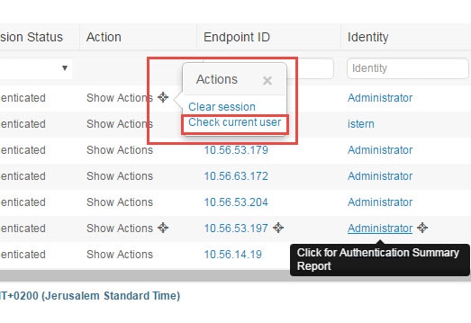
For more information about endpoint user status, and manually running the check, See the RADIUS Live Sessions section in Cisco ISE Admin Guide: Troubleshooting .
When the Endpoint probe recognizes that a user has connected, if 4 hours have passed since the last time the session was updated for the specific endpoint, then it checks whether that user is still logged in and collects the following data:
-
MAC address
-
Operating system version
Based on the this check, the probe does the following:
-
When the user is still logged in, the probe updates ISE with the status Active User.
-
When the user has logged out, the session state is updated as Terminated and fifteen minutes later, the user is removed from the Session Directory.
-
When the user cannot be contacted, for example, when a firewall prevents contact or the endpoint has shut down, the status is updated as Unreachable and the Subscriber policy will determine how to handle the user session. The endpoint will remain in the Session Directory.
Work with the Endpoint Probe
Before you begin
Create and enable Endpoint probes based on subnet ranges. One Endpoint probe can be created per PSN. To work with Endpoint probes, first ensure you have configured the following:
-
Endpoints must have network connectivity to port 445.
-
From ISE, configure an initial Active Directory join point and ensure you select Select Credentials when prompted. For more information about join points, see Active Directory as a Probe and a Provider.
Note
In order to ensure Endpoint runs in the background, you must first configure an initial Active Directory join point, which enables the Endpoint probe to run even when the Active Directory probe is not fully configured.
Procedure
| Step 1 |
Choose and then choose Endpoint Probes. |
| Step 2 |
Click Add to create a new Endpoint probe. |
| Step 3 |
Complete the mandatory fields, ensuring you select Enable from the Status field, and click Submit. See Endpoint Probe Settings for more information. |
Endpoint Probe Settings
Create a single Endpoint probe per PSN, based on subnet ranges. If you have multiple PSNs in your deployment, then you can allot each PSN for a separate set of subnets, and in so doing, use each probe for a different group of users.
Choose and then choose Endpoint Probes to configure a new Endpoint Probe for your PSN.
| Field | Description |
|---|---|
|
Name |
Enter a unique name by which to identify the use of this probe. |
|
Description |
Enter a unique description that explains the use for this probe. |
|
Status |
Choose Enable in order to activate this probe. |
|
Host Name |
Choose a PSN for this probe from the list of available PSNs in your deployment. |
|
Subnets |
Enter the subnet range for the group of endpoints that should be checked by this probe. Use standard subnet mask ranges and separate subnet addresses with commas. For example: 10.56.14.111/32,1.1.1.1/24,2.55.2.0/16,2.2.3.0/16,1.2.3.4/32 Each range must be unique and separate from all other ranges. For example, you cannot enter the following ranges for the same probe because they overlap with each other: 2.2.2.0/16,2.2.3.0/16 |
Subscribers
The Passive Identity services use Cisco pxGrid services to deliver authenticated user identities that are collected from various providers and stored by the Cisco ISE session directory, to other network systems such as Cisco Stealthwatch or Cisco Firepower Management Center (FMC).
Subscribers connected to Cisco ISE must register to use the pxGrid services. Subscribers should adopt the pxGrid Client Library available from Cisco through the pxGrid SDK to become the clients. A subscriber can log in to pxGrid using a unique name and certificate-based mutual authentication. Once they have sent a valid certificate, Cisco pxGrid subscribers are automatically approved by ISE.
Subscribers can connect to either a configured pxGrid server hostname or an IP Address. We recommend that you use hostname to avoid unnecessary errors, particularly to ensure the DNS queries work properly. Capabilities are information topics or channels that are created on pxGrid for subscribers to publish and subscribe. In Cisco ISE, only SessionDirectory and IdentityGroup are supported. You can view capability information is available from the publisher through publish, directed query, or bulk download query, by navigating to Subscribers in the Capabilities tab.
To enable subscribers to receive information from ISE, you must:
-
Optionally, generate a certificate from the subscriber's side.
-
Generate pxGrid Certificates for Subscribers from the PassiveID work center.
-
Enable Subscribers. Either perform this step, or automatically enable approvals, in order to allow subscribers to receive user identities from ISE. See Configure Subscriber Settings.
Generate pxGrid Certificates for Subscribers
Before you begin
You can generate certificates for pxGrid subscribers in order to guarantee mutual trust between pxGrid and the subscribers, thereby enabling user identities to be passed from ISE to the subscribers. To perform the following task, you must be a Super Admin or System Admin.
Procedure
| Step 1 |
Choose and go to the Certificates tab. |
||
| Step 2 |
Select one of the following options from the I want to drop-down list:
|
||
| Step 3 |
(optional) You can enter a description for this certificate. |
||
| Step 4 |
View or edit the pxGrid Certificate template on which this certificate is based. Certificate templates contain properties that are common to all certificates issued by the Certificate Authority (CA) based on that template. The certificate template defines the Subject, Subject Alternative Name (SAN), key type, key size, SCEP RA profile that must be used, validity period of the certificate, and the extended key usage (EKU) that specifies whether the certificate has to be used for client or server authentication or both. The internal Cisco ISE CA (ISE CA) uses a certificate template to issue certificates based on that template. To edit this template choose . |
||
| Step 5 |
Specify the Subject Alternative Name (SAN). You can add multiple SANs. The following options are available:
|
||
| Step 6 |
Select one of the following options from the Certificate Download Format drop-down list:
|
||
| Step 7 |
Enter a certificate password. |
||
| Step 8 |
Click Create. |
Enable Subscribers
Before you begin
-
Enable the pxGrid persona on at least one node to view the requests from the Cisco pxGrid clients.
-
Enable Passive Identity Service. For more information, see Easy Connect.
Procedure
| Step 1 |
Choose and ensure you are viewing the Clients tab. |
| Step 2 |
Check the checkbox next to the subscriber and click Approve. |
| Step 3 |
Click Refresh to view the latest status. |
View Subscriber Events from Live Logs
The Live Logs page displays all the Subscriber events. Event information includes the subscriber and capability names along with the event type and timestamp.
Navigate to and select the Live Log tab to view the list of events. You can also clear the logs and resynchronize or refresh the list.
Configure Subscriber Settings
Before you begin
To perform the following task, you must be a Super Admin or System Admin.
Procedure
| Step 1 |
Choose . |
| Step 2 |
Select the following options based on your requirements:
|
| Step 3 |
Click Save. |
Monitoring and Troubleshooting Service in PassiveID Work Center
Learn about how you can manage PassiveID Work Center with monitoring, troubleshooting and reporting tools.
-
See the RADIUS Live Sessions section in Cisco ISE Admin Guide: Troubleshooting
-
See the Cisco ISE Alarms section in Cisco ISE Admin Guide: Troubleshooting
-
See the Reports section in Cisco ISE Admin Guide: Maintain and Monitor
-
See the TCP Dump Utility to Validate the Incoming Traffic section in Cisco ISE Admin Guide: Troubleshooting
LDAP
Lightweight Directory Access Protocol (LDAP) is a networking protocol defined by RFC 2251 for querying and modifying directory services that run on TCP/IP. LDAP is a lightweight mechanism for accessing an X.500-based directory server.
Cisco ISE integrates with an LDAP external database, which is also called an identity source, by using the LDAP protocol.
LDAP Directory Service
LDAP directory service is based on a client-server model. A client starts an LDAP session by connecting to an LDAP server and sending operation requests to the server. The server then sends its responses. One or more LDAP servers contain data from the LDAP directory tree or the LDAP backend database.
The directory service manages a directory, which is a database that holds information. Directory services use a distributed model for storing information, and that information is usually replicated between directory servers.
An LDAP directory is organized in a simple tree hierarchy and can be distributed among many servers. Each server can have a replicated version of the total directory, which is synchronized periodically.
An entry in the tree contains a set of attributes, where each attribute has a name (an attribute type or attribute description) and one or more values. The attributes are defined in a schema.
Each entry has a unique identifier: its distinguished name (DN). This name contains the relative distinguished name (RDN), which is constructed from attributes in the entry, followed by the DN of the parent entry. You can think of the DN as a full filename, and the RDN as a relative filename in a folder.
Multiple LDAP Instances
By creating more than one LDAP instance with different IP addresses or port settings, you can configure Cisco ISE to authenticate using different LDAP servers or different databases on the same LDAP server. Each primary server IP address and port configuration, along with the secondary server IP address and port configuration, forms an LDAP instance that corresponds to one Cisco ISE LDAP identity source instance.
Cisco ISE does not require that each LDAP instance correspond to a unique LDAP database. You can have more than one LDAP instance set to access the same database. This method is useful when your LDAP database contains more than one subtree for users or groups. Because each LDAP instance supports only one subtree directory for users and one subtree directory for groups, you must configure separate LDAP instances for each user directory and group directory subtree combination for which Cisco ISE submits authentication requests.
LDAP Failover
Cisco ISE supports failover between a primary LDAP server and a secondary LDAP server. A failover occurs when an authentication request fails because Cisco ISE could not connect to an LDAP server because it is down or is otherwise unreachable.
If you establish failover settings and the first LDAP server that Cisco ISE attempts to contact cannot be reached, Cisco ISE always attempts to contact a second LDAP server. If you want Cisco ISE to use the first LDAP server again, you must enter a value in the Failback Retry Delay text box.
Note |
Cisco ISE always uses the primary LDAP server to obtain groups and attributes for use in authorization policies from the Admin portal, so the primary LDAP server must be accessible when you configure these items. Cisco ISE uses the secondary LDAP server only for authentications and authorizations at run time, according to the failover configuration. |
LDAP Connection Management
Cisco ISE supports multiple concurrent LDAP connections. Connections are opened on demand at the time of the first LDAP authentication. The maximum number of connections is configured for each LDAP server. Opening connections in advance shortens the authentication time. You can set the maximum number of connections to use for concurrent binding connections. The number of open connections can be different for each LDAP server (primary or secondary) and is determined based on the maximum number of administration connections configured for each server.
Cisco ISE retains a list of open LDAP connections (including the binding information) for each LDAP server that is configured in Cisco ISE. During the authentication process, the connection manager attempts to find an open connection from the pool. If an open connection does not exist, a new one is opened.
If the LDAP server closed the connection, the connection manager reports an error during the first call to search the directory, and tries to renew the connection. After the authentication process is complete, the connection manager releases the connection.
LDAP User Authentication
You can configure LDAP as an external identity store. Cisco ISE uses plain password authentication. User authentication includes:
-
Searching the LDAP server for an entry that matches the username in the request.
-
Checking the user password with the one that is found in the LDAP server.
-
Retrieving a group’s membership information for use in policies.
-
Retrieving values for specified attributes for use in policies and authorization profiles.
To authenticate a user, Cisco ISE sends a bind request to the LDAP server. The bind request contains the DN and password of the user in clear text. If the DN and password of the user match the username and password in the LDAP directory, then the user is authenticated.
When Active Directory is used as LDAP, UPN names are used for user authentication. When Sun ONE Directory Server is used as LDAP, SAM names are used for user authentication
Note |
Cisco ISE sends two searchRequest messages for every user authentication. This does not impact Cisco ISE authorization or network performance. The second LDAP request is to make sure the Ciso ISE is talking to the right identity. |
Note |
Cisco ISE as a DNS client, uses only the first IP returned in the DNS response to perform the LDAP bind. |
We recommend that you protect the connection to the LDAP server using Secure Sockets Layer (SSL).
Note |
Password change is supported for LDAP only if there are remaining grace logins for the account after the password has expired. If password change is successful, the LDAP server's bindResponse is LDAP_SUCCESS, and includes the remaining grace logins control field in the bindResponse message. If the bindResponse message contains any additional control fields (other than remaining grace logins), Cisco ISE might not be able to decode the message. |
LDAP Group and Attribute Retrieval for Use in Authorization Policies
Cisco ISE can authenticate a subject (user or host) against an LDAP identity source by performing a bind operation on the directory server to find and authenticate the subject. After a successful authentication, Cisco ISE can retrieve groups and attributes that belong to the subject whenever they are required. You can configure the attributes to retrieve in the Cisco ISE Admin portal by choosing . These groups and attributes can be used by Cisco ISE to authorize the subject.
To authenticate a user or query the LDAP identity source, Cisco ISE connects to the LDAP server and maintains a connection pool.
You should note the following restrictions on group memberships when Active Directory is configured as an LDAP store:
-
Users or computers must be direct members of the group defined in the policy conditions to match the policy rule.
-
The defined group may not be a user’s or computer’s primary group. This restriction is applicable only when Active Directory is configured as an LDAP store.
LDAP Group Membership Information Retrieval
For user authentication, user lookup, and MAC address lookup, Cisco ISE must retrieve group membership information from LDAP databases. LDAP servers represent the association between a subject (a user or a host) and a group in one of the following ways:
-
Groups Refer to Subjects—The group objects contain an attribute that specifies the subject. Identifiers for subjects can be sourced in the group as the following:
-
Distinguished names
-
Plain usernames
-
-
Subjects Refer to Groups—The subject objects contain an attribute that specifies the group to which they belong.
LDAP identity sources contain the following parameters for group membership information retrieval:
-
Reference direction—This parameter specifies the method to use when determining group membership (either groups to subjects or subjects to groups).
-
Group map attribute—This parameter indicates the attribute that contains group membership information.
-
Group object class—This parameter determines that certain objects are recognized as groups.
-
Group search subtree—This parameter indicates the search base for group searches.
-
Member type option—This parameter specifies how members are stored in the group member attribute (either as DNs or plain usernames).
LDAP Attributes Retrieval
For user authentication, user lookup, and MAC address lookup, Cisco ISE must retrieve the subject attributes from LDAP databases. For each instance of an LDAP identity source, an identity source dictionary is created. These dictionaries support attributes of the following data types:
-
String
-
Unsigned integer 32
-
IPv4 address
For unsigned integers and IPv4 attributes, Cisco ISE converts the strings that it has retrieved to the corresponding data types. If conversion fails or if no values are retrieved for the attributes, Cisco ISE logs a debug message, but the authentication or lookup process does not fail.
You can optionally configure default values for the attributes that Cisco ISE can use when the conversion fails or when Cisco ISE does not retrieve any values for the attributes.
LDAP Certificate Retrieval
If you have configured certificate retrieval as part of user lookup, then Cisco ISE must retrieve the value of the certificate attribute from LDAP. To retrieve the value of the certificate attribute from LDAP, you must have previously configured the certificate attribute in the list of attributes to be accessed while configuring an LDAP identity source.
Errors Returned by the LDAP Server
The following errors can occur during the authentication process:
-
Authentication Errors—Cisco ISE logs authentication errors in the Cisco ISE log files.
Possible reasons for an LDAP server to return binding (authentication) errors include the following:
-
Parameter errors—Invalid parameters were entered
-
User account is restricted (disabled, locked out, expired, password expired, and so on)
-
Initialization Errors—Use the LDAP server timeout settings to configure the number of seconds that Cisco ISE should wait for a response from an LDAP server before determining that the connection or authentication on that server has failed.
Possible reasons for an LDAP server to return an initialization error are:
-
LDAP is not supported.
-
The server is down.
-
The server is out of memory.
-
The user has no privileges.
-
Administrator credentials are configured incorrectly.
-
-
The following errors are logged as external resource errors, indicating a possible problem with the LDAP server:
-
A connection error occurred
-
The timeout expired
-
The server is down
-
The server is out of memory
The following error is logged as an Unknown User error:
-
A user does not exist in the database
The following error is logged as an Invalid Password error, where the user exists, but the password sent is invalid:
-
An invalid password was entered
LDAP User Lookup
Cisco ISE supports the user lookup feature with an LDAP server. This feature allows you to search for a user in the LDAP database and retrieve information without authentication. The user lookup process includes the following actions:
-
Searching the LDAP server for an entry that matches the username in the request
-
Retrieving a user’s group membership information for use in policies
-
Retrieving values for specified attributes for use in policies and authorization profiles
LDAP MAC Address Lookup
Cisco ISE supports the MAC address lookup feature. This feature allows you to search for a MAC address in the LDAP database and retrieve information without authentication. The MAC address lookup process includes the following actions:
-
Searching the LDAP server for an entry that matches the MAC address of the device
-
Retrieving a MAC Address group information for the device for use in policies
-
Retrieving values for specified attributes for use in policies
Add LDAP Identity Sources
Before you begin
-
To perform the following task, you must be a Super Admin or System Admin.
-
Cisco ISE always uses the primary LDAP server to obtain groups and attributes for use in authorization policies. Therefore, your primary LDAP server must be reachable when you configure these items.
Procedure
| Step 1 |
Choose > LDAP > Add. |
| Step 2 |
Enter the values. |
| Step 3 |
Click Submit to create an LDAP instance. |
LDAP Identity Source Settings
The following table describes the fields on the LDAP Identity Sources page, which you can use to create an LDAP instance and connect to it. The navigation path for this page is: .
LDAP General Settings
The following table describes the fields in the General tab.
|
Fields |
Usage Guidelines |
||
|---|---|---|---|
|
Name |
Enter a name for the LDAP instance. This value is used in searches to obtain the subject DN and attributes. The value is of type string and the maximum length is 64 characters. |
||
|
Description |
Enter a description for the LDAP instance. This value is of type string, and has a maximum length of 1024 characters. |
||
|
Schema |
You can choose any one of the following built-in schema types or create a custom schema:
|
||
|
|||
|
Subject Objectclass |
Enter a value to be used in searches to obtain the subject DN and attributes. The value is of type string and the maximum length is 256 characters. |
||
|
Subject Name Attribute |
Enter the name of the attribute containing the username in the request. The value is of type string and the maximum length is 256 characters. |
||
|
Group Name Attribute |
Enter CN or DN or any supported attribute in the Group Name Attribute field.
|
||
|
Certificate Attribute |
Enter the attribute that contains the certificate definitions. For certificate-based authentication, these definitions are used to validate certificates that are presented by clients. |
||
|
Group Objectclass |
Enter a value to be used in searches to specify the objects that are recognized as groups. The value is of type string and the maximum length is 256 characters. |
||
|
Group Map Attribute |
Specifies the attribute that contains the mapping information. This attribute can be a user or group attribute based on the reference direction that is chosen. |
||
|
Subject Objects Contain Reference To Groups |
Click this radio button if the subject objects contain an attribute that specifies the group to which they belong. |
||
|
Group Objects Contain Reference To Subjects |
Click this radio button if the group objects contain an attribute that specifies the subject. This value is the default value. |
||
|
Subjects in Groups Are Stored in Member Attribute As |
(Only available when you select the Group Objects Contain Reference To Subjects radio button) Specifies how members are sourced in the group member attribute and defaults to the DN. |
||
|
User Info Attributes |
By default, predefined attributes are used to collect user information (such as, first name, last name, email, telephone, locality, and so on) for the following built-in schema types:
If you edit the attributes of the predefined schema, Cisco ISE automatically creates a Custom schema. You can also select the Custom option from the Schema drop-down list to edit the user information attributes based on your requirements. |
||
LDAP Connection Settings
The following table describes the fields in the Connection Settings tab.
|
Fields |
Usage Guidelines |
|---|---|
|
Enable Secondary Server |
Check this option to enable the secondary LDAP server to be used as a backup if the primary LDAP server fails. If you check this check box, you must enter configuration parameters for the secondary LDAP server. |
|
Primary and Secondary Servers |
|
|
Hostname/IP |
Enter the IP address or DNS name of the machine that is running the LDAP software. The hostname can contain from 1 to 256 characters or a valid IP address expressed as a string. The only valid characters for hostnames are alphanumeric characters (a to z, A to Z, 0 to 9), the dot (.), and the hyphen (-). |
|
Port |
Enter the TCP/IP port number on which the LDAP server is listening. Valid values are from 1 to 65,535. The default is 389, as stated in the LDAP specification. If you do not know the port number, you can find this information from the LDAP server administrator. |
|
Specify server for each ISE node |
Check this check box to configure primary and secondary LDAP server hostnames/IP and their ports for each PSN. When this option is enabled, a table listing all the nodes in the deployment is displayed. You need to select the node and configure the primary and secondary LDAP server hostname/IP and their ports for the selected node. |
|
Access |
Anonymous Access—Click to ensure that searches on the LDAP directory occur anonymously. The server does not distinguish who the client is and will allow the client read access to any data that is configured as accessible to any unauthenticated client. In the absence of a specific policy permitting authentication information to be sent to a server, a client should use an anonymous connection. Authenticated Access—Click to ensure that searches on the LDAP directory occur with administrative credentials. If so, enter information for the Admin DN and Password fields. |
|
Admin DN |
Enter the DN of the administrator. The Admin DN is the LDAP account that has permission to search all required users under the User Directory Subtree and to search groups. If the administrator specified does not have permission to see the group name attribute in searches, group mapping fails for users who are authenticated by that LDAP server. |
|
Password |
Enter the LDAP administrator account password. |
|
Secure Authentication |
Click to use SSL to encrypt communication between Cisco ISE and the primary LDAP server. Verify that the Port field contains the port number used for SSL on the LDAP server. If you enable this option, you must choose a root CA. |
|
LDAP Server Root CA |
Choose a trusted root certificate authority from the drop-down list to enable secure authentication with a certificate. |
|
Server Timeout |
Enter the number of seconds that Cisco ISE waits for a response from the primary LDAP server before determining that the connection or authentication with that server has failed. Valid values are 1 to 99. The default is 10. |
|
Max. Admin Connections |
Enter the maximum number of concurrent connections (greater than 0) with LDAP administrator account permissions that can run for a specific LDAP configuration. These connections are used to search the directory for users and groups under the User Directory Subtree and the Group Directory Subtree. Valid values are 1 to 99. The default is 20. |
|
Force reconnect every N seconds |
Check this check box and enter the desired value in the Seconds text box to force the server to renew LDAP connection at the specified time interval. The valid range is from 1 to 60 minutes. |
|
Test Bind to Server |
Click to test and ensure that the LDAP server details and credentials can successfully bind. If the test fails, edit your LDAP server details and retest. |
|
Failover |
|
|
Always Access Primary Server First |
Click this option if you want Cisco ISE to always access the primary LDAP server first for authentications and authorizations. |
|
Failback to Primary Server After |
If the primary LDAP server that Cisco ISE attempts to contact cannot be reached, Cisco ISE attempts to contact the secondary LDAP server. If you want Cisco ISE to use the primary LDAP server again, click this option and enter a value in the text box. |
LDAP Directory Organization Settings
The following table describes the fields in the Directory Organization tab.
|
Fields |
Usage Guidelines |
||
|---|---|---|---|
|
Subject Search Base |
Enter the DN for the subtree that contains all subjects. For example: o=corporation.com If the tree containing subjects is the base DN, enter: o=corporation.com or dc=corporation,dc=com as applicable to your LDAP configuration. For more information, refer to your LDAP database documentation. |
||
|
Group Search Base |
Enter the DN for the subtree that contains all groups. For example: ou=organizational unit, ou=next organizational unit, o=corporation.com If the tree containing groups is the base DN, type: o=corporation.com or dc=corporation,dc=com as applicable to your LDAP configuration. For more information, refer to your LDAP database documentation. |
||
|
Search for MAC Address in Format |
Enter a MAC Address format for Cisco ISE to use for search in the LDAP database. MAC addresses in internal identity sources are sourced in the format xx-xx-xx-xx-xx-xx. MAC addresses in LDAP databases can be sourced in different formats. However, when Cisco ISE receives a host lookup request, Cisco ISE converts the MAC address from the internal format to the format that is specified in this field. Use the drop-down list to enable searching for MAC addresses in a specific format, where <format> can be any one of the following:
The format you choose must match the format of the MAC address sourced in the LDAP server. |
||
|
Strip Start of Subject Name Up To the Last Occurrence of the Separator |
Enter the appropriate text to remove domain prefixes from usernames. If, in the username, Cisco ISE finds the delimiter character that is specified in this field, it strips all characters from the beginning of the username through the delimiter character. If the username contains more than one of the characters that are specified in the <start_string> box, Cisco ISE strips characters through the last occurrence of the delimiter character. For example, if the delimiter character is the backslash (\) and the username is DOMAIN\user1, Cisco ISE submits user1 to an LDAP server.
|
||
|
Strip End of Subject Name from the First Occurrence of the Separator |
Enter the appropriate text to remove domain suffixes from usernames. If, in the username, Cisco ISE finds the delimiter character that is specified in this field, it strips all characters from the delimiter character through the end of the username. If the username contains more than one of the characters that are specified in this field, Cisco ISE strips characters starting with the first occurrence of the delimiter character. For example, if the delimiter character is @ and the username is user1@domain, then Cisco ISE submits user1 to the LDAP server.
|
LDAP Group Settings
|
Fields |
Usage Guidelines |
|---|---|
|
Add |
Choose Add > Add Group to add a new group or choose Add > Select Groups From Directory to select the groups from the LDAP directory. If you choose to add a group, enter a name for the new group. If you are selecting from the directory, enter the filter criteria, and click Retrieve Groups. Check the check boxes next to the groups that you want to select and click OK. The groups that you have selected will appear in the Groups page. |
LDAP Attribute Settings
|
Fields |
Usage Guidelines |
|---|---|
|
Add |
Choose Add > Add Attribute to add a new attribute or choose Add > Select Attributes From Directory to select attributes from the LDAP server. If you choose to add an attribute, enter a name for the new attribute. If you are selecting from the directory, enter the username and click Retrieve Attributes to retrieve the user’s attributes. Check the check boxes next to the attributes that you want to select, and then click OK. |
LDAP Advanced Settings
The following table describes the field in the Advanced Settings tab.
|
Fields |
Usage Guidelines |
|---|---|
|
Enable Password Change |
Check this check box to enable the user to change the password in case of password expiry or password reset while using PAP protocol for device admin and RADIUS EAP-GTC protocol for network access. User authentication fails for the unsupported protocols. This option also enables the user to change the password on their next login. |
Configure LDAP Schema
Procedure
| Step 1 |
Choose Administration > Identity Management > External Identity Sources > LDAP. |
| Step 2 |
Select the LDAP instance. |
| Step 3 |
Click the General tab. |
| Step 4 |
Click the drop-down arrow near the Schema option. |
| Step 5 |
Select the required schema from the Schema drop-down list. You can select the Custom option to update the attributes based on your requirements. Predefined attributes are used for the built-in schema, such as Active Directory, Sun directory Server, Novell eDirectory. If you edit the attributes of the predefined schema, Cisco ISE automatically creates a custom schema. |
Configure Primary and Secondary LDAP Servers
After you create an LDAP instance, you must configure the connection settings for the primary LDAP server. Configuring a secondary LDAP server is optional.
Procedure
| Step 1 |
Choose . |
| Step 2 |
Check the check box next to the LDAP instance that you want to edit and click Edit. |
| Step 3 |
Click the Connection tab to configure the primary and secondary servers. |
| Step 4 |
Enter the values as described in LDAP Identity Source Settings. |
| Step 5 |
Click Submit to save the connection parameters. |
Enable Cisco ISE to Obtain Attributes from the LDAP Server
For Cisco ISE to obtain user and group data from an LDAP server, you must configure LDAP directory details in Cisco ISE. For LDAP identity source, the following three searches are applicable:
-
Search for all groups in group subtree for administration
-
Search for user in subject subtree to locate user
-
Search for groups in which the user is a member
Procedure
| Step 1 |
Choose > LDAP. |
| Step 2 |
Check the check box next to the LDAP instance that you want to edit and click Edit. |
| Step 3 |
Click the Directory Organization tab. |
| Step 4 |
Enter the values as described in LDAP Identity Source Settings. |
| Step 5 |
Click Submit to save the configuration. |
Retrieve Group Membership Details from the LDAP Server
You can add new groups or select groups from the LDAP directory.
Procedure
| Step 1 |
Choose . |
| Step 2 |
Check the check box next to the LDAP instance that you want to edit and click Edit. |
| Step 3 |
Click the Groups tab. |
| Step 4 |
Choose to add a new group or choose to select the groups from the LDAP directory.
|
| Step 5 |
Check the check boxes next to the groups that you want to select and click OK. The groups that you have selected will appear in the Groups page. |
| Step 6 |
Click Submit to save the group selection. |
Note |
Active Directory built-in groups are not supported when Active Directory is configured as LDAP Identity Store in Cisco ISE. |
Retrieve User Attributes From the LDAP Server
You can obtain user attributes from the LDAP server for use in authorization policies.
Procedure
| Step 1 |
Choose . |
| Step 2 |
Check the check box next to the LDAP instance that you want to edit and click Edit. |
| Step 3 |
Click the Attributes tab. |
| Step 4 |
Choose to add a new attribute or choose to select attributes from the LDAP server.
Cisco ISE allows you to configure the LDAP server with IPv4 or IPv6 address for user authentication when you manually add the attribute type IP. |
| Step 5 |
Check the check boxes next to the attributes that you want to select, then click OK. |
| Step 6 |
Click Submit to save the attribute selections. |
Enable Secure Authentication with LDAP Identity Source
When you choose the Secure Authentication option in the LDAP configuration page, Cisco ISE uses SSL to secure communication with the LDAP identity source. Secure connection to LDAP identity source is established using:
-
SSL tunnel—Using SSL v3 or TLS v1 (the strongest version supported by the LDAP server)
-
Server authentication (authentication of LDAP server)—Certificate based
-
Client authentication (authentication of Cisco ISE)—None (Administrator bind is used inside the SSL tunnel)
-
Cipher suites—All cipher suites supported by Cisco ISE
We recommend that you use TLS v1 with the strongest encryption and ciphers that Cisco ISE supports.
To enable Cisco ISE to communicate securely with the LDAP identity source:
Before you begin
-
Cisco ISE must be connected to an LDAP server
-
TCP port 636 should be open
Procedure
| Step 1 |
Import the full Certificate Authority (CA) chain of the CA that issued the server certificate to the LDAP server in to Cisco ISE (). The full CA chain refers to the root CA and intermediate CA certificates; not the LDAP server certificate. |
| Step 2 |
Configure Cisco ISE to use secure authentication when communicating with the LDAP identity source (; be sure to check the Secure Authentication check box in the Connection Settings tab). |
| Step 3 |
Select the root CA certificate in the LDAP identity store. |
ODBC Identity Source
You can use an Open Database Connectivity (ODBC)-compliant database as an external identity source to authenticate users and endpoints. ODBC identity source can be used in an identity store sequence and for Guest and Sponsor authentications. It can also be used for BYOD flow.
The following database engines are supported:
-
MySQL
-
Oracle
-
PostgreSQL
-
Microsoft SQL Server
-
Sybase
Configuring Cisco ISE to authenticate against an ODBC-compliant database does not affect the configuration of the database. To manage your database, refer to your database documentation.
Credential Check for ODBC Database
Cisco ISE supports three different types of credential check for an ODBC database. You must configure appropriate SQL stored procedure for each credential check type. uses the stored procedure to query the appropriate tables in the ODBC database and receive the output parameters and/or recordset from ODBC database. The database can return a recordset or a set of named parameters in response to an ODBC query.
The password can be stored in an ODBC database in clear text or encrypted format. The stored procedure can decrypt it back to clear text when it is called by Cisco ISE.
| Credential Check Type |
ODBC Input Parameters |
ODBC Output Parameters |
Credential Check |
Authentication Protocols |
||
|---|---|---|---|---|---|---|
|
Plain text password authentication in ODBC database |
Username Password |
Result Group Account Info Error string |
If the username and password are matched, relevant user information is returned. |
PAP EAP-GTC (as inner method of PEAP or EAP-FAST) TACACS |
||
|
Plain text password fetching from ODBC database |
Username |
Result Group Account Info Error string Password |
If the username is found, its password and relevant user information is returned by the stored procedure. Cisco ISE calculates the password hash based on the authentication method and compares it with the one received from the client. |
CHAP MSCHAPv1/v2 EAP-MD5 LEAP EAP-MSCHAPv2 (as inner method of PEAP or EAP-FAST) TACACS |
||
|
Lookup |
Username |
Result Group Account Info Error string
|
If the username is found, relevant user information is returned. |
MAB Fast reconnect of PEAP, EAP-FAST, and EAP-TTLS |
The following table lists the mapping between the result codes returned by the ODBC database stored procedure and Cisco ISE authentication result codes:
|
Result code (returned by the stored procedure) |
Description |
Cisco ISE authentication result code |
|---|---|---|
|
0 |
CODE_SUCCESS |
NA (authentication passed) |
|
1 |
CODE_UNKNOWN_USER |
UnknownUser |
|
2 |
CODE_INVALID_PASSWORD |
Failed |
|
3 |
CODE_UNKNOWN_USER_OR_INVALID_PASSWORD |
UnknownUser |
|
4 |
CODE_INTERNAL_ERROR |
Error |
|
10001 |
CODE_ACCOUNT_DISABLED |
DisabledUser |
|
10002 |
CODE_PASSWORD_EXPIRED |
NotPerformedPasswordExpired |
Note |
Cisco ISE performs the actual authentication/lookup operation based on this mapped authentication result code. |
You can use the stored procedures to fetch groups and attributes from the ODBC database.
Sample procedure that returns recordset for plain text password authentication (for Microsoft SQL Server)
CREATE PROCEDURE [dbo].[ISEAuthUserPlainReturnsRecordset]
        @username varchar(64), @password varchar(255)
AS
BEGIN
        IF EXISTS( SELECT  username
        FROM  NetworkUsers
        WHERE  username  = @username
        AND  password  = @password )
        SELECT 0,11,'give full access','No Error'
        FROM  NetworkUsers
        WHERE  username  = @username
        ELSE
        SELECT 3,0,'odbc','ODBC Authen Error'
END
Sample procedure that returns recordset for plain text password fetching (for Microsoft SQL Server)
CREATE PROCEDURE [dbo].[ISEFetchPasswordReturnsRecordset]
        @username varchar(64)
AS
BEGIN
        IF EXISTS( SELECT  username
        FROM  NetworkUsers
        WHERE  username  = @username)
        SELECT 0,11,'give full access','No Error',password
        FROM  NetworkUsers
        WHERE  username  = @username
        ELSE
        SELECT 3,0,'odbc','ODBC Authen Error'
END
Sample procedure that returns recordset for Lookup (for Microsoft SQL Server)
CREATE PROCEDURE [dbo].[ISEUserLookupReturnsRecordset]
        @username varchar(64)
AS
BEGIN
        IF EXISTS( SELECT  username
        FROM  NetworkUsers
        WHERE  username  = @username)
        SELECT 0,11,'give full access','No Error'
        FROM  NetworkUsers
        WHERE  username  = @username
        ELSE
        SELECT 3,0,'odbc','ODBC Authen Error'
END
Sample procedure that returns parameters for plain text password authentication (for Microsoft SQL Server)
CREATE PROCEDURE [dbo].[ISEAuthUserPlainReturnsParameters]
        @username varchar(64), @password varchar(255), @result INT OUTPUT, @group varchar(255) OUTPUT, @acctInfo varchar(255) OUTPUT, @errorString varchar(255) OUTPUT
AS
BEGIN
        IF EXISTS( SELECT  username
        FROM  NetworkUsers
        WHERE  username  = @username
        AND  password  = @password )
        SELECT @result=0, @group=11, @acctInfo='give full access', @errorString='No Error'
        FROM  NetworkUsers
        WHERE  username  = @username
        ELSE
        SELECT @result=3, @group=0, @acctInfo='odbc',  @errorString='ODBC Authen Error'
END
Sample procedure that returns parameters for plain text password fetching (for Microsoft SQL Server)
CREATE PROCEDURE [dbo].[ISEFetchPasswordReturnsParameters]
        @username varchar(64), @result INT OUTPUT, @group varchar(255) OUTPUT, @acctInfo varchar(255) OUTPUT, @errorString varchar(255) OUTPUT, @password varchar(255) OUTPUT
AS
BEGIN
        IF EXISTS( SELECT  username
        FROM  NetworkUsers
        WHERE  username  = @username)
        SELECT @result=0, @group=11, @acctInfo='give full access', @errorString='No Error', @password=password
        FROM  NetworkUsers
        WHERE  username  = @username
        ELSE
        SELECT @result=3, @group=0, @acctInfo='odbc', @errorString='ODBC Authen Error'
END
Sample procedure that returns parameters for Lookup (for Microsoft SQL Server)
CREATE PROCEDURE [dbo].[ISEUserLookupReturnsParameters]
        @username varchar(64), @result INT OUTPUT, @group varchar(255) OUTPUT, @acctInfo varchar(255) OUTPUT, @errorString varchar(255) OUTPUT
AS
BEGIN
        IF EXISTS( SELECT  username
        FROM  NetworkUsers
        WHERE  username  = @username)
        SELECT @result=0, @group=11, @acctInfo='give full access', @errorString='No Error'
        FROM  NetworkUsers
        WHERE  username  = @username
        ELSE
        SELECT @result=3, @group=0, @acctInfo='odbc', @errorString='ODBC Authen Error'
END
Sample procedure that fetches groups from Microsoft SQL Server
CREATE PROCEDURE [dbo].[ISEGroupsH]
        @username varchar(64), @result int output
AS
BEGIN
        if exists (select * from NetworkUsers where username = @username)
        begin
                set @result = 0
                select 'accountants', 'engineers', 'sales','test_group2'
        end
        else
                set @result = 1
END
Sample procedure that fetches all the groups of all the users if the username is "*" (for Microsoft SQL Server)
ALTER PROCEDURE [dbo].[ISEGroupsH]
                @username varchar(64), @result int output
AS
BEGIN
                if @username = '*'
                begin
                                -- if username is equal to '*' then return all existing groups
                                set @result = 0
                                select 'accountants', 'engineers', 'sales','test_group1','test_group2','test_group3','test_group4'
                end
                else
                if exists (select * from NetworkUsers where username = @username)
                begin
                                set @result = 0
                                select 'accountants'
                end
                else
                                set @result = 1
END
Sample procedure that fetches attributes from Microsoft SQL Server
CREATE PROCEDURE [dbo].[ISEAttrsH]
        @username varchar(64), @result int output
AS
BEGIN
        if exists (select * from NetworkUsers where username = @username)
        begin
                set @result = 0
                                select phone as phone, username as username, department as department, floor as floor, memberOf as memberOf, isManager as isManager from NetworkUsers where username = @username
        end
        else
                set @result = 1
END
Add ODBC Identity Source
Before you begin
To perform the following task, you must be a Super Admin or System Admin.
Procedure
| Step 1 |
Choose Administration > Identity Management > External Identity Sources. |
| Step 2 |
Click ODBC. |
| Step 3 |
Click Add. |
| Step 4 |
In the General tab, enter a name and description for the ODBC identity source. |
| Step 5 |
In the Connection tab, enter the following details:
|
| Step 6 |
Click Test Connection to check the connectivity with the ODBC database and to verify the existence of the stored procedures for the configured use cases. |
| Step 7 |
In the Stored Procedures tab, enter the following details:
|
| Step 8 |
Add the required attributes in the Attributes tab. While adding an attribute, you can specify how the attribute name should appear in the authorization policy rules. You can also fetch the attributes from the ODBC database. You can retrieve the attributes from the ODBC database by using both the username and MAC address. String, boolean, and integer attributes are supported. These attributes can be used in the authorization policies. |
| Step 9 |
Add the user groups in the Groups tab. You can also fetch the groups from the ODBC database by specifying the username or MAC address. These groups can be used in the authorization policies. You can rename the groups and attributes. By default, the name that is displayed in the "Name in ISE" field is same as that in ODBC database, however, you can modify this name. This name is used in the authorization policies. |
| Step 10 |
Click Submit. |
RADIUS Token Identity Sources
A server that supports the RADIUS protocol and provides authentication, authorization, and accounting (AAA) services to users and devices is called a RADIUS server. A RADIUS identity source is simply an external identity source that contains a collection of subjects and their credentials and uses the RADIUS protocol for communication. For example, the Safeword token server is an identity source that can contain several users and their credentials as one-time passwords that provides an interface that you can query using the RADIUS protocol.
Cisco ISE supports any RADIUS RFC 2865-compliant server as an external identity source. Cisco ISE supports multiple RADIUS token server identities, for example the RSA SecurID server and the SafeWord server. RADIUS identity sources can work with any RADIUS token server that is used to authenticate a user.
Note |
The Process Host Lookup option must be enabled for MAB authentication. We recommend that you don’t configure the RADIUS token server that is used as the external identity source, for MAB authentication, because the devices that are using MAB authentication cannot generate an OTP or a RADIUS token (which is required for RADIUS token server authentication). Hence, the authentication will fail. You can use the external RADIUS server option to process the MAB requests. |
RADIUS Token Server Supported Authentication Protocols
Cisco ISE supports the following authentication protocols for RADIUS identity sources:
-
RADIUS PAP
-
Protected Extensible Authentication Protocol (PEAP) with inner Extensible Authentication Protocol-Generic Token Card (EAP-GTC)
-
EAP-FAST with inner EAP-GTC
Ports Used By the RADIUS Token Servers for Communication
RADIUS token servers use the UDP port for authentication sessions. This port is used for all RADIUS communication. For Cisco ISE to send RADIUS one-time password (OTP) messages to a RADIUS-enabled token server, you must ensure that the gateway devices between Cisco ISE and the RADIUS-enabled token server allow communication over the UDP port. You can configure the UDP port through the Admin portal.
RADIUS Shared Secret
You must provide a shared secret while configuring RADIUS identity sources in Cisco ISE. This shared secret should be the same as the shared secret that is configured on the RADIUS token server.
Failover in RADIUS Token Servers
Cisco ISE allows you to configure multiple RADIUS identity sources. Each RADIUS identity source can have primary and secondary RADIUS servers. When Cisco ISE is unable to connect to the primary server, it uses the secondary server.
Configurable Password Prompt in RADIUS Token Servers
RADIUS identity sources allow you to configure the password prompt. You can configure the password prompt through the Admin portal.
RADIUS Token Server User Authentication
Cisco ISE obtains the user credentials (username and passcode) and passes them to the RADIUS token server. Cisco ISE also relays the results of the RADIUS token server authentication processing to the user.
User Attribute Cache in RADIUS Token Servers
RADIUS token servers, by default, do not support user lookups. However, the user lookup functionality is essential for the following Cisco ISE features:
-
PEAP session resume: —This feature allows the PEAP session to resume after successful authentication during EAP session establishment.
-
EAP/FAST fast reconnect: This feature allows fast reconnection after successful authentication during EAP session establishment.
-
TACACS+ Authorization: Happens after a successful TACACS+ authentication.
Cisco ISE caches the results of successful authentications to process user lookup requests for these features. For every successful authentication, the name of the authenticated user and the retrieved attributes are cached. Failed authentications are not written to the cache.
The cache is available in the memory at runtime and is not replicated between Cisco ISE nodes in a distributed deployment. You can configure the Time to Live (TTL) limit for the cache through the Admin portal. Starting with ISE 2.6, you may choose to enable the identity caching option and set the aging time in minutes. The option is disabled by default and when enabled, the cache will be available in the memory for the specified amount of time.
RADIUS Identity Source in Identity Sequence
You can add the RADIUS identity source for authentication sequence in an identity source sequence. However, you cannot add the RADIUS identity source for attribute retrieval sequence because you cannot query the RADIUS identity source without authentication. Cisco ISE cannot distinguish among different errors while authenticating with a RADIUS server. RADIUS servers return an Access-Reject message for all errors. For example, when a user is not found in the RADIUS server, instead of returning a User Unknown status, the RADIUS server returns an Access-Reject message.
RADIUS Server Returns the Same Message for All Errors
When a user is not found in the RADIUS server, the RADIUS server returns an Access-Reject message. Cisco ISE provides an option to configure this message through the Admin portal as either an Authentication Failed or a User Not Found message. However, this option returns a User Not Found message not only for cases where the user is not known, but for all failure cases.
The following table lists the different failure cases that are possible with RADIUS identity servers.
|
Failure Cases |
Reasons for Failure |
|---|---|
|
Authentication Failed |
|
|
Process Failed |
|
|
Unknown User |
Authentication failed and the Fail on Reject option is set to false. |
Safeword Server Supports Special Username Format
The Safeword token server supports authentication with the following username format:
Username—Username, OTP
As soon as Cisco ISE receives the authentication request, it parses the username and converts it to the following username:
Username—Username
The SafeWord token servers support both of these formats. Cisco ISE works with various token servers. While configuring a SafeWord server, you must check the SafeWord Server check box in the Admin portal for Cisco ISE to parse the username and convert it to the specified format. This conversion is done in the RADIUS token server identity source before the request is sent to the RADIUS token server.
Authentication Request and Response in RADIUS Token Servers
When Cisco ISE forwards an authentication request to a RADIUS-enabled token server, the RADIUS authentication request contains the following attributes:
-
User-Name (RADIUS attribute 1)
-
User-Password (RADIUS attribute 2)
-
NAS-IP-Address (RADIUS attribute 4)
Cisco ISE expects to receive any one of the following responses:
-
Access-Accept—No attributes are required, however, the response can contain a variety of attributes based on the RADIUS token server configuration.
-
Access-Reject—No attributes are required.
-
Access-Challenge—The attributes that are required per RADIUS RFC are the following:
-
State (RADIUS attribute 24)
-
Reply-Message (RADIUS attribute 18)
-
One or more of the following attributes: Vendor-Specific, Idle-Timeout (RADIUS attribute 28), Session-Timeout (RADIUS attribute 27), Proxy-State (RADIUS attribute 33)
No other attributes are allowed in Access-Challenge.
-
RADIUS Token Identity Sources Settings
| Fields | Usage Guidelines |
|---|---|
|
Name |
Enter a name for the RADIUS token server. The maximum number of characters allowed is 64. |
|
Description |
Enter a description for the RADIUS token server. The maximum number of characters is 1024. |
|
SafeWord Server |
Check this check box if your RADIUS identity source is a SafeWord server. |
|
Enable Secondary Server |
Check this check box to enable the secondary RADIUS token server for Cisco ISE to use as a backup in case the primary fails. If you check this check box, you must configure a secondary RADIUS token server. |
|
Always Access Primary Server First |
Click this radio button if you want Cisco ISE to always access the primary server first. |
|
Fallback to Primary Server after |
Click this radio button to specify the amount of time in minutes that Cisco ISE can authenticate using the secondary RADIUS token server if the primary server cannot be reached. After this time elapses, Cisco ISE reattempts to authenticate against the primary server. |
| Primary Server | |
|
Host IP |
Enter the IP address of the primary RADIUS token server. This field can take as input a valid IP address that is expressed as a string. Valid characters that are allowed in this field are numbers and dot (.). |
|
Shared Secret |
Enter the shared secret that is configured on the primary RADIUS token server for this connection. |
|
Authentication Port |
Enter the port number on which the primary RADIUS token server is listening. |
|
Server Timeout |
Specify the time in seconds that Cisco ISE should wait for a response from the primary RADIUS token server before it determines that the primary server is down. |
|
Connection Attempts |
Specify the number of attempts that Cisco ISE should make to reconnect to the primary server before moving on to the secondary server (if defined) or dropping the request if a secondary server is not defined. |
| Secondary Server | |
|
Host IP |
Enter the IP address of the secondary RADIUS token server. This field can take as input a valid IP address that is expressed as a string. Valid characters that are allowed in this field are numbers and dot (.). |
|
Shared Secret |
Enter the shared secret configured on the secondary RADIUS token server for this connection. |
|
Authentication Port |
Enter the port number on which the secondary RADIUS token server is listening. Valid values are from 1 to 65,535. The default is 1812. |
|
Server Timeout |
Specify the time in seconds that Cisco ISE should wait for a response from the secondary RADIUS token server before it determines that the secondary server is down. |
|
Connection Attempts |
Specify the number of attempts that Cisco ISE should make to reconnect to the secondary server before dropping the request. |
Add a RADIUS Token Server
Before you begin
To perform the following task, you must be a Super Admin or System Admin.
Procedure
| Step 1 |
Choose . |
||||
| Step 2 |
Enter the values in the General and Connection tabs. |
||||
| Step 3 |
Click the Authentication tab. This tab allows you to control the responses to an Access-Reject message from the RADIUS token server. This response could either mean that the credentials are invalid or that the user is not known. Cisco ISE accepts one of the following responses: Failed authentication or User not found. This tab also allows you to enable identity caching and to set the aging time for the cache. You can also configure a prompt to request the password.
|
||||
| Step 4 |
Check the Enable Passcode Caching check box if you want Cisco ISE to store the passcode in the cache after the first successful authentication with an RADIUS token server and use the cached user credentials for the subsequent authentications if they happen within the configured time period. Enter the number of seconds for which the passcode must be stored in the cache in the Aging Time field. Within this period of time, the user can perform more than one authentication with the same passcode. The default value is 30 seconds. The valid range is from 1 to 300 seconds.
|
||||
| Step 5 |
Click the Authorization tab. This tab allows you to configure a name that will appear for the attribute that is returned by the RADIUS token server while sending an Access-Accept response to Cisco ISE. This attribute can be used in authorization policy conditions. The default value is CiscoSecure-Group-Id.
|
||||
| Step 6 |
Click Submit. |
Delete a RADIUS Token Server
Before you begin
-
To perform the following task, you must be a Super Admin or System Admin.
-
Ensure that you do not select the RADIUS token servers that are part of an identity source sequence. If you select a RADIUS token server that is part of an identity source sequence for deletion, the delete operation fails.
Procedure
| Step 1 |
Choose . |
| Step 2 |
Check the check box next to the RADIUS token server or servers that you want to delete, then click Delete. |
| Step 3 |
Click OK to delete the RADIUS token server or servers that you have selected. If you select multiple RADIUS token servers for deleting, and one of them is used in an identity source sequence, the delete operation fails and none of the RADIUS token servers are deleted. |
RSA Identity Sources
Cisco ISE supports the RSA SecurID server as an external database. RSA SecurID two-factor authentication consists of the PIN of the user and an individually registered RSA SecurID token that generates single-use token codes based on a time code algorithm. A different token code is generated at fixed intervals (usually each at 30 or 60 seconds). The RSA SecurID server validates this dynamic authentication code. Each RSA SecurID token is unique, and it is not possible to predict the value of a future token based on past tokens. Thus, when a correct token code is supplied together with a PIN, there is a high degree of certainty that the person is a valid user. Therefore, RSA SecurID servers provide a more reliable authentication mechanism than conventional reusable passwords.
Cisco ISE supports the following RSA identity sources:
-
RSA ACE/Server 6.x series
-
RSA Authentication Manager 7.x and 8.0 series
You can integrate with RSA SecurID authentication technology in any one of the following ways:
-
Using the RSA SecurID agent—Users are authenticated with their username and passcode through the RSA native protocol.
-
Using the RADIUS protocol—Users are authenticated with their username and passcode through the RADIUS protocol.
The RSA SecurID token server in Cisco ISE connects with the RSA SecurID authentication technology by using the RSA SecurID Agent.
Cisco ISE supports only one RSA realm.
Cisco ISE and RSA SecurID Server Integration
These are the two administrative roles involved in connecting Cisco ISE with an RSA SecurID server:
-
RSA Server Administrator—Configures and maintains RSA systems and integration
-
Cisco ISE Administrator—Configures Cisco ISE to connect to the RSA SecurID server and maintains the configuration
This section describes the processes that are involved in connecting Cisco ISE with the RSA SecurID server as an external identity source. For more information on RSA servers, please refer to the RSA documentation.
RSA Configuration in Cisco ISE
The RSA administrative system generates an sdconf.rec file, which the RSA system administrator will provide to you. This file allows you to add Cisco ISE servers as RSA SecurID agents in the realm. You have to browse and add this file to Cisco ISE. By the process of replication, the primary Cisco ISE server distributes this file to all the secondary servers.
RSA Agent Authentication Against the RSA SecurID Server
After the sdconf.rec file is installed on all Cisco ISE servers, the RSA agent module initializes, and authentication with RSA-generated credentials proceeds on each of the Cisco ISE servers. After the agent on each of the Cisco ISE servers in a deployment has successfully authenticated, the RSA server and the agent module together download the securid file. This file resides in the Cisco ISE file system and is in a well-known place defined by the RSA agent.
RSA Identity Sources in a Distributed Cisco ISE Environment
Managing RSA identity sources in a distributed Cisco ISE environment involves the following:
-
Distributing the sdconf.rec and sdopts.rec files from the primary server to the secondary servers.
-
Deleting the securid and sdstatus.12 files.
RSA Server Updates in a Cisco ISE Deployment
After you have added the sdconf.rec file in Cisco ISE, the RSA SecurID administrator might update the sdconf.rec file in case of decommissioning an RSA server or adding a new RSA secondary server. The RSA SecurID administrator will provide you with an updated file. You can then reconfigure Cisco ISE with the updated file. The replication process in Cisco ISE distributes the updated file to the secondary Cisco ISE servers in the deployment. Cisco ISE first updates the file in the file system and coordinates with the RSA agent module to phase the restart process appropriately. When the sdconf.rec file is updated, the sdstatus.12 and securid files are reset (deleted).
Override Automatic RSA Routing
You can have more than one RSA server in a realm. The sdopts.rec file performs the role of a load balancer. Cisco ISE servers and RSA SecurID servers operate through the agent module. The agent module that resides on Cisco ISE maintains a cost-based routing table to make the best use of the RSA servers in the realm. You can, however, choose to override this routing with a manual configuration for each Cisco ISE server for the realm using a text file called sdopts.rec through the Admin portal. Refer to the RSA documentation for information on how to create this file.
RSA Node Secret Reset
The securid file is a secret node key file. When RSA is initially set up, it uses a secret to validate the agents. When the RSA agent that resides in Cisco ISE successfully authenticates against the RSA server for the first time, it creates a file on the client machine called securid and uses it to ensure that the data exchanged between the machines is valid. At times, you may have to delete the securid file from a specific Cisco ISE server or a group of servers in your deployment (for example, after a key reset on the RSA server). You can use the Cisco ISE Admin portal to delete this file from a Cisco ISE server for the realm. When the RSA agent in Cisco ISE authenticates successfully the next time, it creates a new securid file.
Note |
If authentications fail after upgrading to a latest release of Cisco ISE, reset the RSA secret. |
RSA Automatic Availability Reset
The sdstatus.12 file provides information about the availability of RSA servers in the realm. For example, it provides information on which servers are active and which are down. The agent module works with the RSA servers in the realm to maintain this availability status. This information is serially listed in the sdstatus.12 file, which is sourced in a well-known location in the Cisco ISE file system. Sometimes this file becomes old and the current status is not reflected in this file. You must remove this file so that the current status can be recreated. You can use the Admin portal to delete the file from a specific Cisco ISE server for a specific realm. Cisco ISE coordinates with the RSA agent and ensures correct restart phasing.
The availability file sdstatus.12 is deleted whenever the securid file is reset, or the sdconf.rec or sdopts.rec files are updated.
RSA SecurID Identity Source Settings
RSA Prompt Settings
The following table describes the fields in the RSA Prompts tab.
|
Fields |
Usage Guidelines |
|---|---|
|
Enter Passcode Prompt |
Enter a text string to obtain the passcode. |
|
Enter Next Token Code |
Enter a text string to request the next token. |
|
Choose PIN Type |
Enter a text string to request the PIN type. |
|
Accept System PIN |
Enter a text string to accept the system-generated PIN. |
|
Enter Alphanumeric PIN |
Enter a text string to request an alphanumeric PIN. |
|
Enter Numeric PIN |
Enter a text string to request a numeric PIN. |
|
Re-enter PIN |
Enter a text string to request the user to re-enter the PIN. |
RSA Message Settings
The following table describes the fields in the RSA Messages tab.
|
Fields |
Usage Guidelines |
|---|---|
|
Display System PIN Message |
Enter a text string to label the system PIN message. |
|
Display System PIN Reminder |
Enter a text string to inform the user to remember the new PIN. |
|
Must Enter Numeric Error |
Enter a message that instructs users to enter only numbers for the PIN. |
|
Must Enter Alpha Error |
Enter a message that instructs users to enter only alphanumeric characters for PINs. |
|
PIN Accepted Message |
Enter a message that the users see when their PIN is accepted by the system. |
|
PIN Rejected Message |
Enter a message that the users see when the system rejects their PIN. |
|
User Pins Differ Error |
Enter a message that the users see when they enter an incorrect PIN. |
|
System PIN Accepted Message |
Enter a message that the users see when the system accepts their PIN. |
|
Bad Password Length Error |
Enter a message that the users see when the PIN that they specify does not fall within the range specified in the PIN length policy. |
Add RSA Identity Sources
To create an RSA identity source, you must import the RSA configuration file (sdconf.rec). You must obtain the sdconf.rec file from your RSA administrator. To perform this task, you must be a Super Admin or System Admin.
Adding an RSA identity source involves the following tasks:Import the RSA Configuration File
You must import the RSA configuration file to add an RSA identity source in Cisco ISE.
Procedure
| Step 1 |
Choose . |
| Step 2 |
Click Browse to choose the new or updated sdconf.rec file from the system that is running your client browser. When you create the RSA identity source for the first time, the Import new sdconf.rec file field will be a mandatory field. From then on, you can replace the existing sdconf.rec file with an updated one, but replacing the existing file is optional. |
| Step 3 |
Enter the server timeout value in seconds. Cisco ISE will wait for a response from the RSA server for the amount of time specified before it times out. This value can be any integer from 1 to 199. The default value is 30 seconds. |
| Step 4 |
Check the Reauthenticate on Change PIN check box to force a reauthentication when the PIN is changed. |
| Step 5 |
Click Save. Cisco ISE also
supports the following scenarios:
|
Configure the Options File for a Cisco ISE Server and Resetting SecurID and sdstatus.12 Files
Procedure
| Step 1 |
Log into the Cisco ISE server. |
| Step 2 |
Choose . |
| Step 3 |
Click the RSA Instance Files tab. This page lists the sdopts.rec files for all the Cisco ISE servers in your deployment. The Node Secret Status is displayed as Created when the user is authenticated against RSA SecurID token server. The Node Secret Status can be one of the following—Created or Not Created. The Node Secret Status is displayed as Not Created when it is cleared. |
| Step 4 |
Click the radio button next to the sdopts.rec file for a particular Cisco ISE server, and click Update Options File. The existing file is displayed in the Current File region. |
| Step 5 |
Choose one of the following:
|
| Step 6 |
Click OK. |
| Step 7 |
Click the row that corresponds to the Cisco ISE server to reset the securid and sdstatus.12 files for that server: |
| Step 8 |
Click Save. |
Configure Authentication Control Options for RSA Identity Source
You can specify how Cisco ISE defines authentication failures and enable identity caching. The RSA identity source does not differentiate between “Authentication failed” and “User not found” errors and sends an Access-Reject response.
You can define how Cisco ISE should handle such failures while processing requests and reporting failures. Identity caching enables Cisco ISE to process requests that fail to authenticate against the Cisco ISE server the second time. The results and the attributes retrieved from the previous authentication are available in the cache.
Procedure
| Step 1 |
Choose . |
||||
| Step 2 |
Click the Authentication Control tab. |
||||
| Step 3 |
Choose one of the following:
|
||||
| Step 4 |
Check the Enable Passcode Caching check box if you want Cisco ISE to store the passcode in the cache after the first successful authentication and use the cached user credentials for the subsequent authentications if they happen within the configured time period. Enter the number of seconds for which the passcode must be stored in the cache in the Aging Time field. Within this period of time, the user can perform more than one authentication with the same passcode. The default value is 30 seconds. The valid range is from 1 to 300 seconds.
|
||||
| Step 5 |
Check the Enable Identity Caching check box if you want to enable ISE to process requests that fail to authenticate against the Cisco ISE server the second time. |
||||
| Step 6 |
Click Save to save the configuration. |
Configure RSA Prompts
Cisco ISE allows you to configure RSA prompts that are presented to the user while processing requests sent to the RSA SecurID server.
Before you begin
To perform the following task, you must be a Super Admin or System Admin.
Procedure
| Step 1 |
Choose . |
| Step 2 |
Click Prompts. |
| Step 3 |
Enter the values as described in RSA SecurID Identity Source Settings. |
| Step 4 |
Click Submit. |
Configure RSA Messages
Cisco ISE allows you to configure messages that are presented to the user while processing requests sent to the RSA SecurID server.
Before you begin
To perform the following task, you must be a Super Admin or System Admin.
Procedure
| Step 1 |
Choose . |
| Step 2 |
Click Prompts. |
| Step 3 |
Click the Messages tab. |
| Step 4 |
Enter the values as described in RSA SecurID Identity Source Settings. |
| Step 5 |
Click Submit. |
SAMLv2 Identity Provider as an External Identity Source
Security Assertion Markup Language (SAML) is an XML-based open standard data format that enables administrators to access a defined set of applications seamlessly after signing into one of those applications. SAML describes the exchange of security related information between trusted business partners. SAML enables exchange of security authentication information between an Identity Provider (IdP) and a service provider (in this case, ISE).
SAML Single Sign On (SSO) establishes a Circle of Trust (CoT) by exchanging metadata and certificates as part of the provisioning process between the IdP and the Service Provider. The Service Provider trusts the IdP's user information to provide access to the various services or applications.
Enabling SAML SSO results in several advantages:
-
It reduces password fatigue by removing the need for entering different user name and password combinations.
-
It improves productivity because you spend less time re-entering credentials for the same identity.
-
It transfers the authentication from your system that hosts the applications to a third party system.
-
It reduces costs as fewer help desk calls are made for password reset, thereby leading to more savings.
The IdP is an authentication module that creates, maintains, and manages identity information for users, systems, or services. The IdP stores and validates the user credentials and generates a SAML response that allows the user to access the service provider protected resources.
Note |
You must be familiar with your IdP service, and ensure that it is currently installed and operational. |
SAML SSO is supported for the following portals:
-
Guest portal (sponsored and self-registered)
-
Sponsor portal
-
My Devices portal
-
Certificate Provisioning portal
You cannot select IdP as external identity source for BYOD portal, but you can select an IdP for a guest portal and enable BYOD flow.
Cisco ISE is SAMLv2 compliant and supports all SAMLv2 compliant IdPs that use Base64-encoded certificates. The IdPs listed below have been tested with Cisco ISE:
-
Oracle Access Manager (OAM)
-
Oracle Identity Federation (OIF)
-
SecureAuth
-
PingOne
-
PingFederate
-
Azure Active Directory
The IdP cannot be added to an identity source sequence.
The SSO session will be terminated and Session Timeout error message will be displayed if there is no activity for the specified time (default is 5 minutes).
If you want to add the Sign On Again button in the Error page of the portal, add the following JavaScript in the Optional Content field in the Portal Error page:
<button class="cisco-ise"
                     		  data-inline="true" data-mini="true" data-theme="b" id="ui_aup_accept_button"
                     		  onclick="location.href='PortalSetup.action?portal=<Portal ID>'"
                     		  type="button">SignOn Again</button>
Add a SAML Identity Provider
Before you begin
To perform the following task, you must be a Super Admin or System Admin.
Procedure
| Step 1 |
Import the Certificate Authority (CA) certificate in to the Trusted Certificate Store, if the certificate is not self-signed by the IdP. Choose Administration > System > Certificates > Trusted Certificates > Import to import the CA certificate. |
||||
| Step 2 |
Choose Work Centers > Network Access > Ext Id Sources. |
||||
| Step 3 |
Click SAML Id Providers. |
||||
| Step 4 |
Click Add. |
||||
| Step 5 |
In the SAML Identity Provider page, enter the following details: |
||||
| Step 6 |
Click Submit. |
||||
| Step 7 |
Go to the Portal Settings page (Guest, Sponsor, Certificate Provisioning, or My Devices portal) and select the IdP that you want to link to that portal in the Authentication Method field. To access the Portal Settings page:
|
||||
| Step 8 |
Click Save. |
||||
| Step 9 |
Choose Work Centers > Network Access > Ext Id Sources > SAML Id Providers. Select the IdP that is linked to that portal and click Edit. |
||||
| Step 10 |
(Optional) In the Service Provider Info tab, add the load balancer details. You can add a load balancer in front of ISE nodes to simplify the configuration on the Identity Provider side and optimize the load on ISE nodes. The load balancer can be a software-based or hardware-based appliance. It should be able to forward the requests to the ISE nodes in the deployment (by using the port specified at the Portal Settings page). When a load balancer is used, only the load balancer URL is provided in the service provider metadata file. If load balancer is not configured, multiple AssertionConsumerService URLs will be included in the service provider metadata file.
|
||||
| Step 11 |
In the Service Provider Info tab, click Export to export the service provider metadata file. The exported metadata includes the signing certificate of Cisco ISE. The signing certificate is identical to the chosen portal's certificate. The exported metadata zip file includes a Readme file that contains the basic instructions for configuring each IdP (such as, Azure Active Directory, PingOne, PingFederate, SecureAuth, and OAM).
|
||||
| Step 12 |
Click Browse in the dialog box and save the compressed files locally. Unzip the metadata file folder. When you unzip the folder, you will get a metadata file with the name of the portal. The metadata file includes the Provider ID and Binding URI. |
||||
| Step 13 |
Login as Admin user in IdP and import the service provider metadata file. Refer to the Identity Provider user documentation for information on how to import the service provider metadata file. |
||||
| Step 14 |
In the Groups tab, add the required user groups. Enter the assertion attribute that specifies the group membership of users in the Group Membership Attribute field. |
||||
| Step 15 |
Add the user attributes in the Attributes tab. While adding an attribute, you can specify how the attribute appears in the assertions returned from the IdP. The name that you specify in the "Name in ISE" field will appear in the policy rules. The following data types are supported for the attributes:
|
||||
| Step 16 |
Configure the following options in the Advanced Settings tab:
|
||||
| Step 17 |
Click Submit. |
Example
Delete an Identity Provider
Before you begin
To perform the following task, you must be a Super Admin or System Admin.
Ensure that the IdP that you want to delete is not linked to any portal. If the IdP is linked to any portal, the delete operation fails.
Procedure
| Step 1 |
Choose Work Centers > Network Access > Ext Id Sources > SAML Id Providers. |
| Step 2 |
Check the check box next to the IdP that you want to delete, and then click Delete. |
| Step 3 |
Click OK to delete the IdP that you have selected. |
Authentication Failure Log
When authentication against SAML ID Store fails and the IdP redirects the user back to ISE portal (through SAML response), ISE will report a failure reason in the authentication log. For Guest portal (with or without BYOD flow enabled), you can check the RADIUS Livelog (Operations > RADIUS > Live Log) to know the authentication failure reason. For My Devices portal and Sponsor portal, you can check the My Devices Login/Audit report and Sponsor Login/Audit report (under Operations > Reports > Guest) to know the authentication failure reason.
In case of logout failure, you can check the reports and logs to know the failure reason for My Devices, Sponsor, and Guest portal.
Authentication can fail due to the following reasons:
-
SAML Response parse errors
-
SAML Response validation errors (for example, Wrong Issuer)
-
SAML Assertion validation errors (for example, Wrong Audience)
-
SAML Response signature validation errors (for example, Wrong Signature)
-
IdP signing certificate errors (for example, Certificate Revoked)
Note |
Cisco ISE does not support SAML responses with encrypted assertions. If this is configured in the IdP, you will see the following
error message in ISE: |
If the authentication fails, we recommend that you check the "DetailedInfo" attribute in the authentication log. This attribute provides additional information regarding the cause of failure.
Identity Source Sequences
Identity source sequences define the order in which Cisco ISE looks for user credentials in the different databases.
If you have user information in more than one of the databases that are connected to Cisco ISE, you can define the order in which you want Cisco ISE to look for information in these identity sources. Once a match is found, Cisco ISE does not look any further, but evaluates the credentials, and returns the result to the user. This policy is the first match policy.
Create Identity Source Sequences
Before you begin
Ensure that you have configured your external identity sources in Cisco ISE.
To perform the following task, you must be a Super Admin or System Admin.
For allowing guest users to authenticate through Local WebAuth, you must configure both the Guest Portal authentication source and the identity source sequence to contain the same identity stores.
Procedure
| Step 1 |
Choose . |
| Step 2 |
Enter a name for the identity source sequence. You can also enter an optional description. |
| Step 3 |
Check the Select Certificate Authentication Profile check box and choose a certificate authentication profile for certificate-based authentication. |
| Step 4 |
Choose the database or databases that you want to include in the identity source sequence in the Selected List box. |
| Step 5 |
Rearrange the databases in the Selected list in the order in which you want Cisco ISE to search the databases. |
| Step 6 |
Choose one of the following options in the Advanced Search List area:
|
| Step 7 |
Click Submit to create the identity source sequence that you can then use in policies. |
Delete Identity Source Sequences
You can delete identity source sequences that you no longer use in policies.
Before you begin
-
Ensure that the identity source sequence that you are about to delete is not used in any authentication policy.
-
To perform the following task, you must be a Super Admin or System Admin.
Procedure
| Step 1 |
Choose . |
| Step 2 |
Check the check box next to the identity source sequence or sequences that you want to delete, then click Delete. |
| Step 3 |
Click OK to delete the identity source sequence or sequences. |
Identity Source Details in Reports
Cisco ISE provides information about the identity sources through the Authentications dashlet and Identity Source reports.
Authentications Dashlet
From the Authentications dashlet, you can drill down to find more information including failure reasons.
Choose Operations > RADIUS Livelog to view real-time authentication summary. For more information about RADIUS Live Logs, see the RADIUS Live Logs section in Cisco ISE Admin Guide: Troubleshooting .
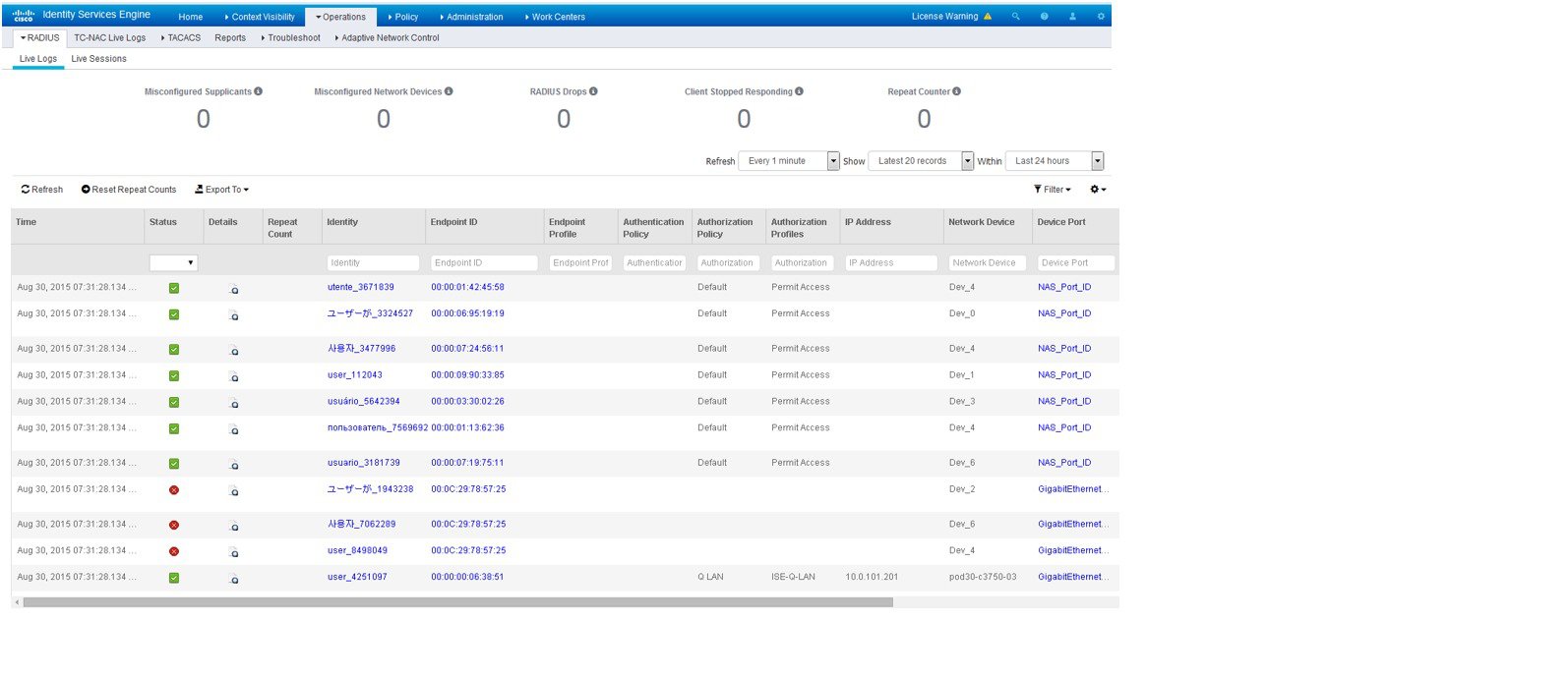
Identity Source Reports
Cisco ISE provides various reports that include information about identity sources. See the Available Reports section for a description of these reports .
Profiled Endpoints on the Network
The Profiler service assists in identifying, locating, and determining the capabilities of all endpoints on your network (known as identities in Cisco ISE), regardless of their device types, to ensure and maintain appropriate access to your enterprise network. The Cisco ISE Profiler function uses a number of probes to collect attributes for all endpoints on your network, and pass them to the Profiler analyzer, where the known endpoints are classified according to their associated policies and identity groups.
The Profiler Feed service allows administrators to retrieve new and updated endpoint profiling policies and the updated OUI database as a feed from a designated Cisco feed server through a subscription in to Cisco ISE.
Profiler Condition Settings
The following table describes the fields in the Profiler Condition window. The navigation path for this window is .
|
Field Name |
Usage Guidelines |
|---|---|
|
Name |
Name of the profiler condition. |
|
Description |
Description of the profiler condition. |
|
Type |
Choose any one of the predefined types. |
|
Attribute Name |
Choose an attribute on which to base the profiler condition. |
|
Operator |
Choose an operator. |
|
Attribute Value |
Enter the value for the attribute that you have chosen. For Attribute Names that contain pre-defined Attribute Values, this option displays a drop-down list with the pre-defined values, and you can choose a value. |
|
System Type |
Profiling conditions can be any one of the following types:
|
Cisco ISE Profiling Service
The profiling service in Cisco Identity Services Engine (ISE) identifies the devices that connect to your network and their location. The endpoints are profiled based on the endpoint profiling policies configured in Cisco ISE. Cisco ISE then grants permission to the endpoints to access the resources in your network based on the result of the policy evaluation.
The profiling service:
-
Facilitates an efficient and effective deployment and ongoing management of authentication by using IEEE standard 802.1X port-based authentication access control, MAC Authentication Bypass (MAB) authentication, and Network Admission Control (NAC) for any enterprise network of varying scale and complexity.
-
Identifies, locates, and determines the capabilities of all of the attached network endpoints regardless of endpoint types.
-
Protects against inadvertently denying access to some endpoints.
Profiler Work Center
The Profiler Work Center menu (Work Centers > Profiler) contains all the profiler pages, which acts as a single start point for ISE administrators. The Profiler Work Center menu contains the following options: Overview, Ext ID Stores, Network Devices, Endpoint Classification, Node Config, Feeds, Manual Scans, Policy Elements, Profiling Policies, Authorization Policy, Troubleshoot, Reports, Settings, and Dictionaries.
Profiler Dashboard
The Profiler dashboard (Work Centers > Profiler > Endpoint Classification) is a centralized monitoring tool for the profiles, endpoints, and assets in your network. The dashboard represents data in both graphical and table formats. The Profiles dashlet displays the logical and endpoint profiles that are currently active in the network. The Endpoints dashlet displays the identity group, PSNs, OS types of the endpoints that connect to your network. The Assets dashlet displays flows such as Guest, BYOD, and Corporate. The table displays the various endpoints that are connected and you can also add new endpoints.
Endpoint Inventory Using Profiling Service
You can use the profiling service to discover, locate, and determine the capabilities of all the endpoints connected to your network. You can ensure and maintain appropriate access of endpoints to the enterprise network, regardless of their device types.
The profiling service collects attributes of endpoints from the network devices and the network, classifies endpoints into a specific group according to their profiles, and stores endpoints with their matched profiles in the Cisco ISE database. All the attributes that are handled by the profiling service need to be defined in the profiler dictionaries.
The profiling service identifies each endpoint on your network, and groups those endpoints according to their profiles to an existing endpoint identity group in the system, or to a new group that you can create in the system. By grouping endpoints, and applying endpoint profiling policies to the endpoint identity group, you can determine the mapping of endpoints to the corresponding endpoint profiling policies.
Cisco ISE Profiler Queue Limit Configuration
Cisco ISE profiler collects a significant amount of endpoint data from the network in a short period of time. It causes Java Virtual Machine (JVM) memory utilization to go up due to accumulated backlog when some of the slower Cisco ISE components process the data generated by the profiler, which results in performance degradation and stability issues.
To ensure that the profiler does not increase the JVM memory utilization and prevent JVM to go out of memory and restart, limits are applied to the following internal components of the profiler:
-
Endpoint Cache—Internal cache is limited in size that has to be purged periodically (based on least recently used strategy) when the size exceeds the limit.
-
Forwarder—The main ingress queue of endpoint information collected by the profiler.
-
Event Handler—An internal queue that disconnects a fast component, which feeds data to a slower processing component (typically related to a database query).
Endpoint Cache
-
maxEndPointsInLocalDb = 100000 (endpoint objects in cache)
-
endPointsPurgeIntervalSec = 300 (endpoint cache purge thread interval in seconds)
-
numberOfProfilingThreads = 8 (number of threads)
The limit is applicable to all profiler internal event handlers. A monitoring alarm is triggered when queue size limit is reached.
Cisco ISE Profiler Queue Size Limits
-
forwarderQueueSize = 5000 (endpoint collection events)
-
eventHandlerQueueSize = 10000 (events)
Event Handlers
-
NetworkDeviceEventHandler—For network device events, in addition to filtering duplicate Network Access Device (NAD) IP addresses, which are already cached.
-
ARPCacheEventHandler—For ARP Cache events.
Configure Profiling Service in Cisco ISE Nodes
You can configure the profiling service that provides you a contextual inventory of all the endpoints that are using your network resources in any Cisco ISE-enabled network.
You can configure the profiling service to run on a single Cisco ISE node that assumes all Administration, Monitoring, and Policy Service personas by default.
In a distributed deployment, the profiling service runs only on Cisco ISE nodes that assume the Policy Service persona and does not run on other Cisco ISE nodes that assume the Administration and Monitoring personas.
Procedure
| Step 1 |
Choose . |
| Step 2 |
Choose a Cisco ISE node that assumes the Policy Service persona. |
| Step 3 |
Click Edit in the Deployment Nodes page. |
| Step 4 |
On the General Settings tab, check the Policy Service check box. If the Policy Service check box is unchecked, both the session services and the profiling service check boxes are disabled. |
| Step 5 |
Perform the following tasks:
|
| Step 6 |
Click Save to save the node configuration. |
Network Probes Used by Profiling Service
Network probe is a method used to collect an attribute or a set of attributes from an endpoint on your network. The probe allows you to create or update endpoints with their matched profile in the Cisco ISE database.
Cisco ISE can profile devices using a number of network probes that analyze the behavior of devices on the network and determine the type of the device. Network probes help you to gain more network visibility.
IP Address and MAC Address Binding
NetFlow Probe
Cisco ISE profiler implements Cisco IOS NetFlow Version 9. We recommend using NetFlow Version 9, which has additional functionality needed to enhance the profiler to support the Cisco ISE profiling service.
You can collect NetFlow Version 9 attributes from the NetFlow-enabled network access devices to create an endpoint, or update an existing endpoint in the Cisco ISE database. You can configure NetFlow Version 9 to attach the source and destination MAC addresses of endpoints and update them. You can also create a dictionary of NetFlow attributes to support NetFlow-based profiling.
For more information on the NetFlow Version 9 Record Format, see Table 6, “NetFlow Version 9 Field Type Definitions” of the NetFlow Version 9 Flow-Record Format document.
In addition, Cisco ISE supports NetFlow versions earlier than Version 5. If you use NetFlow Version 5 in your network, then you can use Version 5 only on the primary network access device (NAD) at the access layer because it will not work anywhere else.
Cisco IOS NetFlow Version 5 packets do not contain MAC addresses of endpoints. The attributes that are collected from NetFlow Version 5 cannot be directly added to the Cisco ISE database. You can discover endpoints by using their IP addresses, and append the NetFlow Version 5 attributes to endpoints, which can be done by combining IP addresses of the network access devices and IP addresses obtained from the NetFlow Version 5 attributes. However, these endpoints must have been previously discovered with the RADIUS or SNMP probe.
The MAC address is not a part of IP flows in earlier versions of NetFlow Version 5, which requires you to profile endpoints with their IP addresses by correlating the attributes information collected from the network access devices in the endpoints cache.
For more information on the NetFlow Version 5 Record Format, see Table 2, “Cisco IOS NetFlow Flow Record and Export Format Content Information” of the NetFlow Services Solutions Guide.
DHCP Probe
The Dynamic Host Configuration Protocol probe in your Cisco ISE deployment, when enabled, allows the Cisco ISE profiling service to reprofile endpoints based only on new requests of INIT-REBOOT, and SELECTING message types. Though other DHCP message types such as RENEWING and REBINDING are processed, they are not used for profiling endpoints. Any attribute parsed out of DHCP packets is mapped to endpoint attributes.
DHCPREQUEST Message Generated During INIT-REBOOT State
If the DHCP client checks to verify a previously allocated and cached configuration, then the client must not fill in the Server identifier (server-ip) option. Instead it should fill in the Requested IP address (requested-ip) option with the previously assigned IP address, and fill in the Client IP Address (ciaddr) field with zero in its DHCPREQUEST message. The DHCP server will then send a DHCPNAK message to the client if the Requested IP address is incorrect or the client is located in the wrong network.
DHCPREQUEST Message Generated During SELECTING State
The DHCP client inserts the IP address of the selected DHCP server in the Server identifier (server-ip) option, fills in the Requested IP address (requested-ip) option with the value of the Your IP Address (yiaddr) field from the chosen DHCPOFFER by the client, and fills in the “ciaddr” field with zero.
|
— |
INIT-REBOOT |
SELECTING |
RENEWING |
REBINDING |
|---|---|---|---|---|
|
broadcast/unicast |
broadcast |
broadcast |
unicast |
broadcast |
|
server-ip |
MUST NOT |
MUST |
MUST NOT |
MUST NOT |
|
requested-ip |
MUST |
MUST |
MUST NOT |
MUST NOT |
|
ciaddr |
zero |
zero |
IP address |
IP address |
Wireless LAN Controller Configuration in DHCP Bridging Mode
DHCP SPAN Probe
The DHCP Switched Port Analyzer (SPAN) probe, when initialized in a Cisco ISE node, listens to network traffic, which are coming from network access devices on a specific interface. You need to configure network access devices to forward DHCP SPAN packets to the Cisco ISE profiler from the DHCP servers. The profiler receives these DHCP SPAN packets and parses them to capture the attributes of an endpoint, which can be used for profiling endpoints.
For example,
switch(config)# monitor session 1 source interface Gi1/0/4
switch(config)# monitor session 1 destination interface Gi1/0/2
HTTP Probe
In HTTP probe, the identification string is transmitted in an HTTP request-header field User-Agent, which is an attribute that can be used to create a profiling condition of IP type, and to check the web browser information. The profiler captures the web browser information from the User-Agent attribute along with other HTTP attributes from the request messages, and adds them to the list of endpoint attributes.
Cisco ISE listens to communication from the web browsers on both port 80 and port 8080. Cisco ISE provides many default profiles, which are built in to the system to identify endpoints based on the User-Agent attribute.
HTTP SPAN Probe
The HTTP probe in your Cisco ISE deployment, when enabled with the Switched Port Analyzer (SPAN) probe, allows the profiler to capture HTTP packets from the specified interfaces. You can use the SPAN capability on port 80, where the Cisco ISE server listens to communication from the web browsers.
HTTP SPAN collects HTTP attributes of an HTTP request-header message along with the IP addresses in the IP header (L3 header), which can be associated to an endpoint based on the MAC address of an endpoint in the L2 header. This information is useful for identifying different mobile and portable IP-enabled devices such as Apple devices, and computers with different operating systems. Identifying different mobile and portable IP-enabled devices is made more reliable because the Cisco ISE server redirects captures during a guest login or client provisioning download. This allows the profiler to collect the User-Agent attribute and other HTTP attributes, from the request messages and then identify devices such as Apple devices.
Unable to Collect HTTP Attributes in Cisco ISE Running on VMware
RADIUS Probe
You can configure Cisco ISE for authentication with RADIUS, where you can define a shared secret that you can use in client-server transactions. With the RADIUS request and response messages that are received from the RADIUS servers, the profiler can collect RADIUS attributes, which can be used for profiling endpoints.
Cisco ISE can function as a RADIUS server, and a RADIUS proxy client to other RADIUS servers. When it acts as a proxy client, it uses external RADIUS servers to process RADIUS requests and response messages.
Note |
When an accounting stop is received, it triggers the Cisco ISE to reprofile the corresponding endpoint if it was originally profiled with an IP address. Therefore if you have custom profiles for endpoints profiled with IP addresses, the only way to meet the total certainty factor for these profiles is to match on the corresponding IP address. |
Network Scan (NMAP) Probe
About the NMAP Probe
Cisco ISE enables you to detect devices in a subnet by using the NMAP security scanner. You enable the NMAP probe on the Policy Service node that is enabled to run the profiling service. You use the results from that probe in an endpoint profiling policy.
Each NMAP manual subnet scan has a unique numeric ID that is used to update an endpoint source information with that scan ID. Upon detection of endpoints, the endpoint source information can also be updated to indicate that it is discovered by the Network Scan probe.
The NMAP manual subnet scan is useful for detecting devices such as printers with a static IP address assigned to them that are connected constantly to the Cisco ISE network, and therefore these devices cannot be discovered by other probes.
NMAP Scan Limitations
Scanning a subnet is highly resource intensive. Scanning a subnet is lengthy process that depends on the size and density of the subnet. Number of active scans is always restricted to one scan, which means that you can scan only a single subnet at a time. You can cancel a subnet scan at any time while the subnet scan is in progress. You can use the Click to see latest scan results link to view the most recent network scan results that are stored in .
Manual NMAP Scan
The following NMAP command scans a subnet and sends the output to nmapSubnet.log:
nmap -O -sU -p U:161,162 -oN /opt/CSCOcpm/logs/nmapSubnet.log
--append-output -oX - <subnet>| -O | Enables OS detection |
| -sU | UDP scan |
| -p <port ranges> | Scans only specified ports. For example, U:161, 162 |
| oN | Normal output |
| oX | XML output |
SNMP Read Only Community Strings for NMAP Manual Subnet Scan
Manual NMAP Scan Results
The most recent network scan results are stored in Work Centers > Profiler > Manual Scans > Manual NMAP Scan Results. The Manaul NMAP Scan Results page displays only the most recent endpoints that are detected, along with their associated endpoint profiles, their MAC addresses, and their static assignment status as the result of a manual network scan you perform on any subnet. This page allows you to edit points that are detected from the endpoint subnet for better classification, if required.
Cisco ISE allows you to perform the manual network scan from the Policy Service nodes that are enabled to run the profiling service. You must choose the Policy Service node from the primary Administration ISE node user interface in your deployment to run the manual network scan from the Policy Service node. During the manual network scan on any subnet, the Network Scan probe detects endpoints on the specified subnet, their operating systems, and check UDP ports 161 and 162 for an SNMP service.
Additional Information
Given below is additional information related to the manual NMAP scan results:
-
To detect unknown endpoints, NMAP should be able to learn the IP/MAC binding via NMAP or a supporting SNMP scan.
-
ISE learns IP/MAC binding of known endpoints via Radius authentication or DHCP profiling.
-
The IP/MAC bindings are not replicated across PSN nodes in a deployment. Therefore, you must trigger the manual scan from the PSN, which has the IP/MAC binding in its local database (for example, the PSN against which a mac address was last authenticated with).
-
The NMAP scan results do not display any information related to an endpoint that NMAP had previously scanned, manually or automatically.
DNS Probe
The Domain Name Service (DNS) probe in your Cisco ISE deployment allows the profiler to lookup an endpoint and get the fully qualified domain name (FQDN). After an endpoint is detected in your Cisco ISE-enabled network, a list of endpoint attributes is collected from the NetFlow, DHCP, DHCP SPAN, HTTP, RADIUS, or SNMP probes.
When you deploy Cisco ISE in a standalone or in a distributed environment for the first time, you are prompted to run the setup utility to configure the Cisco ISE appliance. When you run the setup utility, you will configure the Domain Name System (DNS) domain and the primary nameserver (primary DNS server), where you can configure one or more nameservers during setup. You can also change or add DNS nameservers later after deploying Cisco ISE using the CLI commands.
DNS FQDN Lookup
-
The dhcp-requested-address attribute—An attribute collected by the DHCP and DHCP SPAN probes.
-
The SourceIP attribute—An attribute collected by the HTTP probe
-
The Framed-IP-Address attribute—An attribute collected by the RADIUS probe
-
The cdpCacheAddress attribute—An attribute collected by the SNMP probe
Configure Call Station ID Type in the WLC Web Interface
You can use the WLC web interface to configure Call Station ID Type information. You can go to the Security tab of the WLC web interface to configure the calling station ID in the RADIUS Authentication Servers page. The MAC Delimiter field is set to Colon by default in the WLC user interface.
For more information on how to configure in the WLC web interface, see Chapter 6, “Configuring Security Solutions” in the Cisco Wireless LAN Controller Configuration Guide, Release 7.2.
For more information on how to configure in the WLC CLI using the config radius callStationIdType command, see Chapter 2, “Controller Commands” in the Cisco Wireless LAN Controller Command Reference Guide, Release 7.2.
Procedure
| Step 1 |
Log in to your Wireless LAN Controller user interface. |
| Step 2 |
Click Security. |
| Step 3 |
Expand AAA, and then choose . |
| Step 4 |
Choose System MAC Address from the Call Station ID Type drop-down list. |
| Step 5 |
Check the AES Key Wrap check box when you run Cisco ISE in FIPS mode. |
| Step 6 |
Choose Colon from the MAC Delimeter drop-down list. |
SNMP Query Probe
In addition to configuring the SNMP Query probe in the Edit Node page, you must configure other Simple Management Protocol settings in the following location: .
You can configure SNMP settings in the new network access devices (NADs) in the Network Devices list page. The polling interval that you specify in the SNMP query probe or in the SNMP settings in the network access devices query NADs at regular intervals.
You can turn on and turn off SNMP querying for specific NADs based on the following configurations:
-
SNMP query on Link up and New MAC notification turned on or turned off
-
SNMP query on Link up and New MAC notification turned on or turned off for Cisco Discovery Protocol information
-
SNMP query timer for once an hour for each switch by default
For an iDevice, and other mobile devices that do not support SNMP, the MAC address can be discovered by the ARP table, which can be queried from the network access device by an SNMP Query probe.
Cisco Discovery Protocol Support with SNMP Query
Link Layer Discovery Protocol Support with SNMP Query
| Feature | Feature |
|---|---|
| LLDP global state | Disabled |
| LLDP holdtime (before discarding) | 120 seconds |
| LLDP timer (packet update frequency) | 30 seconds |
| LLDP reinitialization delay | 2 seconds |
| LLDP tlv-select | Enabled to send and receive all TLVs. |
| LLDP interface state | Enabled |
| LLDP receive | Enabled |
| LLDP transmit | Enabled |
| LLDP med-tlv-select | Enabled to send all LLDP-MED TLVs |
CDP and LLDP Capability Codes Displayed in a Single Character
Example 1
lldpCacheCapabilities S
lldpCapabilitiesMapSupported S
Example 2
lldpCacheCapabilities B;T
lldpCapabilitiesMapSupported B;T
Example 3
Switch#show cdp neighbors
Capability Codes:
R - Router, T - Trans Bridge, B - Source Route Bridge, S - Switch, H - Host, I - IGMP,
r - Repeater, P - Phone, D - Remote, C - CVTA, M - Two-port Mac Relay
...
Switch#

Switch#show lldp neighbors
Capability codes:
(R) Router, (B) Bridge, (T) Telephone, (C) DOCSIS Cable Device
(W) WLAN Access Point, (P) Repeater, (S) Station, (O) Other
...
Switch#
SNMP Trap Probe
The SNMP Trap receives information from the specific network access devices that support MAC notification, linkup, linkdown, and informs. The SNMP Trap probe receives information from the specific network access devices when ports come up or go down and endpoints disconnect from or connect to your network, which results in the information received that is not sufficient to create endpoints in Cisco ISE.
For SNMP Trap to be fully functional and create endpoints, you must enable SNMP Query so that the SNMP Query probe triggers a poll event on the particular port of the network access device when a trap is received. To make this feature fully functional you should configure the network access device and SNMP Trap.
Note |
Cisco ISE does not support SNMP Traps that are received from the Wireless LAN Controllers (WLCs) and Access Points (APs). |
Active Directory Probe
The AD probe:
-
Improves the fidelity of OS information for Windows endpoints. Microsoft AD tracks detailed OS information for AD-joined computers including version and service pack levels. The AD probe retrieves this information directly using the AD Runtime connector to provide a highly reliable source of client OS information.
-
Helps distinguish between corporate and non-corporate assets. A basic but important attribute available to the AD probe is whether an endpoint exists in AD. This information can be used to classify an endpoint contained in the AD as a managed device or corporate asset.
You can enable the AD probe under the page. When this probe is enabled, ISE fetches the AD attributes for a new endpoint as soon as it receives a hostname. The hostname is typically learned from the DHCP or DNS probes. Once successfully retrieved, ISE does not attempt to query AD again for the same endpoint until a the rescan timer expires. This is to limit the load on AD for attribute queries. The rescan timer is configurable in the Days Before Rescan field (Administration > System > Deployment > Profiling Configuration > Active Directory). If there is additional profiling activity on the endpoint, the AD is queried again.
-
AD-Host-Exists
-
AD-Join-Point
-
AD-Operating-System
-
AD-OS-Version
-
AD-Service-Pack
Configure Probes per Cisco ISE Node
You can configure one or more probes on the Profiling Configuration tab per Cisco ISE node in your deployment that assumes the Policy Service persona, which could be:
-
A standalone node—If you have deployed Cisco ISE on a single node that assumes all Administration, Monitoring, and Policy Service personas by default.
-
Multiple nodes—If you have registered more than one node in your deployment that assume Policy Service persona.
Before you begin
You can configure the probes per Cisco ISE node only from the Administration node, which is unavailable on the secondary Administration node in a distributed deployment.
Procedure
| Step 1 |
Choose . |
| Step 2 |
Choose a Cisco ISE node that assumes the Policy Service persona. |
| Step 3 |
Click Edit in the Deployment Nodes page. |
| Step 4 |
On the General Settings tab, check the Policy Service check box. If the Policy Service check box is unchecked, both the session services and the profiling service check boxes are disabled. |
| Step 5 |
Check the Enable Profiling Services check box. |
| Step 6 |
Click the Profiling Configuration tab. |
| Step 7 |
Configure the values for each probe. |
| Step 8 |
Click Save to save the probe configuration. |
Setup CoA, SNMP RO Community, and Endpoint Attribute Filter
Cisco ISE allows a global configuration to issue a Change of Authorization (CoA) in the Profiler Configuration page that enables the profiling service with more control over endpoints that are already authenticated.
In addition, you can configure additional SNMP Read Only community strings separated by a comma for the NMAP manual network scan in the Profiler Configuration page. The SNMP RO community strings are used in the same order as they appear in the Current custom SNMP community strings field.
You can also configure endpoint attribute filtering in the Profiler Configuration page.
Procedure
| Step 1 |
Choose . |
| Step 2 |
Choose one of the following settings to configure the CoA type:
|
| Step 3 |
Enter new SNMP community strings separated by a comma for the NMAP manual network scan in the Change custom SNMP community strings field, and re-enter the strings in the Confirm custom SNMP community strings field for confirmation. |
| Step 4 |
Check the Endpoint Attribute Filter check box to enable endpoint attribute filtering. |
| Step 5 |
Click Save. |
Global Configuration of Change of Authorization for Authenticated Endpoints
You can use the global configuration option to disable change of authorization (CoA) by using the default No CoA option or enable CoA by using port bounce and reauthentication options. If you have configured Port Bounce for CoA in Cisco ISE, the profiling service may still issue other CoAs as described in the “CoA Exemptions” section.
You can use the RADIUS probe or the Monitoring persona REST API to authenticate the endpoints. You can enable the RADIUS probe, which allows faster performance. If you have enabled CoA, then we recommend that you enable the RADIUS probe in conjunction with your CoA configuration in the Cisco ISE application for faster performance. The profiling service can then issue an appropriate CoA for endpoints by using the RADIUS attributes that are collected.
If you have disabled the RADIUS probe in the Cisco ISE application, then you can rely on the Monitoring persona REST API to issue CoAs. This allows the profiling service to support a wider range of endpoints. In a distributed deployment, your network must have at least one Cisco ISE node that assumes the Monitoring persona to rely on the Monitoring persona REST API to issue a CoA.
Cisco ISE arbitrarily will designate either the primary or secondary Monitoring node as the default destination for REST queries in your distributed deployment, because both the primary and secondary Monitoring nodes have identical session directory information.
Use Cases for Issuing Change of Authorization
The profiling service issues the change of authorization in the following cases:
-
Endpoint deleted—When an endpoint is deleted from the Endpoints page and the endpoint is disconnected or removed from the network.
-
An exception action is configured—If you have an exception action configured per profile that leads to an unusual or an unacceptable event from that endpoint. The profiling service moves the endpoint to the corresponding static profile by issuing a CoA.
-
An endpoint is profiled for the first time—When an endpoint is not statically assigned and profiled for the first time; for example, the profile changes from an unknown to a known profile.
-
An endpoint identity group has changed—When an endpoint is added or removed from an endpoint identity group that is used by an authorization policy.
The profiling service issues a CoA when there is any change in an endpoint identity group, and the endpoint identity group is used in the authorization policy for the following:
-
The endpoint identity group changes for endpoints when they are dynamically profiled
-
The endpoint identity group changes when the static assignment flag is set to true for a dynamic endpoint
-
-
-
An endpoint profiling policy has changed and the policy is used in an authorization policy—When an endpoint profiling policy changes, and the policy is included in a logical profile that is used in an authorization policy. The endpoint profiling policy may change due to the profiling policy match or when an endpoint is statically assigned to an endpoint profiling policy, which is associated to a logical profile. In both the cases, the profiling service issues a CoA, only when the endpoint profiling policy is used in an authorization policy.
Exemptions for Issuing a Change of Authorization
The profiling service does not issue a CoA when there is a change in an endpoint identity group and the static assignment is already true.
Cisco ISE does not issue a CoA for the following reasons:
-
An Endpoint disconnected from the network—When an endpoint disconnected from your network is discovered.
-
Authenticated wired (Extensible Authentication Protocol) EAP-capable endpoint—When an authenticated wired EAP-capable endpoint is discovered.
-
Multiple active sessions per port—When you have multiple active sessions on a single port, the profiling service issues a CoA with the Reauth option even though you have configured CoA with the Port Bounce option.
-
Packet-of-Disconnect CoA (Terminate Session) when a wireless endpoint is detected—If an endpoint is discovered as wireless, then a Packet-of-Disconnect CoA (Terminate-Session) is issued instead of the Port Bounce CoA. The benefit of this change is to support the Wireless LAN Controller (WLC) CoA.
-
Profiler CoA is suppressed when the Suppress Profiler CoA for endpoints in Logical Profile option is used for the configured logical profile in the Authorization Profile. Profiler CoA will be triggered for all other endpoints by default.
-
Global No CoA Setting overrides Policy CoA—Global No CoA overrides all configuration settings in endpoint profiling policies as there is no CoA issued in Cisco ISE irrespective of CoA configured per endpoint profiling policy.
Note
No CoA and Reauth CoA configurations are not affected, and the profiler service applies the same CoA configuration for wired and wireless endpoints.
Change of Authorization Issued for Each Type of CoA Configuration
|
Scenarios |
No CoA Configuration |
Port Bounce Configuration |
Reauth Configuration |
Additional Information |
|---|---|---|---|---|
|
Global CoA configuration in Cisco ISE (typical configuration) |
No CoA |
Port Bounce |
Reauthentication |
— |
|
An endpoint is disconnected on your network |
No CoA |
No CoA |
No CoA |
Change of authorization is determined by the RADIUS attribute Acct-Status -Type value Stop. |
|
Wired with multiple active sessions on the same switch port |
No CoA |
Reauthentication |
Reauthentication |
Reauthentication avoids disconnecting other sessions. |
|
Wireless endpoint |
No CoA |
Packet-of-Disconnect CoA (Terminate Session) |
Reauthentication |
Support to Wireless LAN Controller. |
|
Incomplete CoA data |
No CoA |
No CoA |
No CoA |
Due to missing RADIUS attributes. |
Attribute Filters for ISE Database Persistence and Performance
Cisco ISE implements filters for Dynamic Host Configuration Protocol (both DHCP Helper and DHCP SPAN), HTTP, RADIUS, and Simple Network Management Protocol probes except for the NetFlow probe to address performance degradation. Each probe filter contains the list of attributes that are temporal and irrelevant for endpoint profiling and removes those attributes from the attributes collected by the probes.
The isebootstrap log (isebootstrap-yyyymmdd-xxxxxx.log) contains messages that handles the creation of dictionaries and with filtering of attributes from the dictionaries. You can also configure to log a debug message when endpoints go through the filtering phase to indicate that filtering has occurred.
The Cisco ISE profiler invokes the following endpoint attribute filters:
-
A DHCP filter for both the DHCP Helper and DHCP SPAN contains all the attributes that are not necessary and they are removed after parsing DHCP packets. The attributes after filtering are merged with existing attributes in the endpoint cache for an endpoint.
-
An HTTP filter is used for filtering attributes from HTTP packets, where there is no significant change in the set of attributes after filtering.
-
A RADIUS filter is used once the syslog parsing is complete and endpoint attributes are merged into the endpoint cache for profiling.
-
SNMP filter for SNMP Query includes separate CDP and LLDP filters, which are all used for SNMP-Query probe.
Global Setting to Filter Endpoint Attributes with Whitelist
You can reduce the number of persistence events and replication events by reducing the number of endpoint attributes that do not change frequently at the collection point. Enabling the EndPoint Attribute Filter will have the Cisco ISE profiler only to keep significant attributes and discard all other attributes. Significant attributes are those used by the Cisco ISE system or those used specifically in a endpoint profiling policy or rule.
A whitelist is a set of attributes that are used in custom endpoint profiling policies for profiling endpoints, and that are essential for Change of Authorization (CoA), Bring Your Own Device (BYOD), Device Registration WebAuth (DRW), and so on to function in Cisco ISE as expected. The whitelist is always used as a criteria when ownership changes for the endpoint (when attributes are collected by multiple Policy Service nodes) even when disabled.
By default, the whitelist is disabled and the attributes are dropped only when the attribute filter is enabled. The white list is dynamically updated when endpoint profiling policies change including from the feed to include new attributes in the profiling policies. Any attribute that is not present in the whitelist is dropped immediately at the time of collection, and the attribute cannot participate in profiling endpoints. When combined with the buffering, the number of persistence events can be reduced.
You must ensure that the whitelist contains a set of attributes determined from the following two sources:
-
A set of attributes that are used in the default profiles so that you can match endpoints to the profiles.
-
A set of attributes that are essential for Change of Authorization (CoA), Bring Your Own Device (BYOD), Device Registration WebAuth (DRW), and so on to function as expected.
|
AAA-Server |
BYODRegistration |
|
Calling-Station-ID |
Certificate Expiration Date |
|
Certificate Issue Date |
Certificate Issuer Name |
|
Certificate Serial Number |
Description |
|
DestinationIPAddress |
Device Identifier |
|
Device Name |
DeviceRegistrationStatus |
|
EndPointPolicy |
EndPointPolicyID |
|
EndPointProfilerServer |
EndPointSource |
|
FQDN |
FirstCollection |
|
Framed-IP-Address |
IdentityGroup |
|
IdentityGroupID |
IdentityStoreGUID |
|
IdentityStoreName |
L4_DST_PORT |
|
LastNmapScanTime |
MACAddress |
|
MatchedPolicy |
MatchedPolicyID |
|
NADAddress |
NAS-IP-Address |
|
NAS-Port-Id |
NAS-Port-Type |
|
NmapScanCount |
NmapSubnetScanID |
|
OS Version |
OUI |
|
PolicyVersion |
PortalUser |
|
PostureApplicable |
Product |
|
RegistrationTimeStamp |
— |
|
StaticAssignment |
StaticGroupAssignment |
|
TimeToProfile |
Total Certainty Factor |
|
User-Agent |
cdpCacheAddress |
|
cdpCacheCapabilities |
cdpCacheDeviceId |
|
cdpCachePlatform |
cdpCacheVersion |
|
ciaddr |
dhcp-class-identifier |
|
dhcp-requested-address |
host-name |
|
hrDeviceDescr |
ifIndex |
|
ip |
lldpCacheCapabilities |
|
lldpCapabilitiesMapSupported |
lldpSystemDescription |
|
operating-system |
sysDescr |
|
161-udp |
— |
Attributes Collection from IOS Sensor Embedded Switches
An IOS sensor integration allows Cisco ISE run time and the Cisco ISE profiler to collect any or all of the attributes that are sent from the switch. You can collect DHCP, CDP, and LLDP attributes directly from the switch by using the RADIUS protocol. The attributes that are collected for DHCP, CDP, and LLDP are then parsed and mapped to attributes in the profiler dictionaries in the following location: .
For information about the supported Catalyst platforms for Device sensors, see https://communities.cisco.com/docs/DOC-72932.
IOS Sensor Embedded Network Access Devices
Integrating IOS sensor embedded network access devices with Cisco ISE involves the following components:
-
An IOS sensor
-
Data collector that is embedded in the network access device (switch) for gathering DHCP, CDP, and LLDP data
-
Analyzers for processing the data and determining the device-type of endpoints
There are two ways of deploying an analyzer, but they are not expected to be used in conjunction with each other:
-
An analyzer can be deployed in Cisco ISE
-
Analyzers can be embedded in the switch as the sensor
-
Configuration Checklist for IOS Sensor-Enabled Network Access Devices
This section summarizes a list of tasks that you must configure in the IOS sensor-enabled switches and Cisco ISE to collect DHCP, CDP, and LLDP attributes directly from the switch:
-
Ensure that the RADIUS probe is enabled in Cisco ISE.
-
Ensure that network access devices support an IOS sensor for collecting DHCP, CDP, and LLDP information.
-
Ensure that network access devices run the following CDP and LLDP commands to capture CDP and LLDP information from endpoints:
cdp enable lldp run -
Ensure that session accounting is enabled separately by using the standard AAA and RADIUS commands.
For example, use the following commands:
aaa new-model aaa accounting dot1x default start-stop group radius radius-server host <ip> auth-port <port> acct-port <port> key <shared-secret> radius-server vsa send accounting -
Ensure that you run IOS sensor-specific commands.
-
Enabling Accounting Augmentation
You must enable the network access devices to add IOS sensor protocol data to the RADIUS accounting messages and to generate additional accounting events when it detects new sensor protocol data. This means that any RADIUS accounting message should include all CDP, LLDP, and DHCP attributes.
Enter the following global command:
device-sensor accounting
-
Disabling Accounting Augmentation
To disable (accounting) network access devices and add IOS sensor protocol data to the RADIUS accounting messages for sessions that are hosted on a given port (if the accounting feature is globally enabled), enter the following command at the appropriate port:
no device-sensor accounting
-
TLV Change Tracking
By default, for each supported peer protocol, client notifications and accounting events are generated only when an incoming packet includes a type, length, and value (TLV) that has not been received previously in the context of a given session.
You must enable client notifications and accounting events for all TLV changes where there are either new TLVs, or where previously received TLVs have different values. Enter the following command:
device-sensor notify all-changes
-
-
Be sure that you disable the IOS Device Classifier (local analyzer) in the network access devices.
Enter the following command:
no macro auto monitor
Note
This command prevents network access devices from sending two identical RADIUS accounting messages per change.
Support for Cisco IND Controllers by the ISE Profiler
ISE can profile and display the status of devices attached to a Cisco Industrial Network Device (IND). PxGrid connects ISE and the Cisco Industrial Network Director to communicate endpoint (IoT) data. pxGrid on ISE consumes CIND events, and queries CIND to update endpoint type.
The ISE profiler has dictionary attributes for IoT devices. Navigate to , and select IOTASSET from the list of System Dictionaries to see the dictionary attributes.
Guidelines and Recommendations
If you have several ISE nodes configured for profiling, we recommend that you enable pxGrid for IND on one node.
If ISE goes down, then when ISE comes back up, you reconnect to IND in CIND. To reconnect, in CIND, navigate to the pxGrid page, and click Reconnect.
Multiple IND devices can connect to a single ISE.
If the same endpoint is received from two or more publishers (IND), ISE only keeps the last publisher's data for that endpoint.
In pxGrid, ISE gets IND data from the service names com.cisco.endpoint.asset, and /topic/com.cisco.endpoint.asset.
IND Profiling Process Flow
CIND Asset discovery finds an IoT device, and publishes the endpoint data for that device to pxGrid. ISE sees the event on pxGrid, and gets the endpoint data. Profiler policies in ISE assign the device data to attributes in the ISE profiler dictionary, and applies those attributes to the endpoint in ISE.
IoT endpoint data which does not meet the existing attributes in ISE are not saved. But you can create more attributes in ISE, and register them with CIND.
ISE does a bulk download of endpoints when the connection to CIND through pxGrid is first established. If there is a network failure, ISE does another bulk download of accumulated endpoint changes.
Configure ISE and CIND for IND Profiling
Note |
You must install the ISE certificate in CIND, and install the CIND certificate in ISE, before you activate pxGrid in CIND. |
-
In ISE, enable pxGrid—Navigate to . Edit the PSN that you plan to use as pxGrid consumer, and enable pxGrid. This PSN is the one that creates endpoints from pxGrid data published by Cisco IND and profiling.
-
In ISE, create a pxGrid certificate—Navigate to to verify that pxGrid is running. Then click the Certificates tab, and fill in the certificate fields. Click Create to issue the certificate, and opens a window for you to select a download directory. The certificate downloads to that directory in a zipped format.
-
For I want to, select “Generate a single certificate (without a certificate signing request), Common Name, enter a name for the CIND you are connecting with.
-
For Certificate Download Format, choose PKS12 format.
-
For Certificate Password, create a password.
Note
The ISE internal CA must be enabled, and if your browser blocks popups, you won’t be able to download the certificate. Unzip the certificate to make the PEM file available for the next step.
-
-
In CIND, export the CIND certificate—In CIND, navigate to , and Click Download .pem IND certificate. Keep this window open.
-
In ISE, navigate to . When you see the IND pxGrid client, approve it.
-
In CIND, move the slider to enable pxGrid. Another screen opens, where you define the location of the ISE node, the name of the certificate that you entered for this pxGrid server in ISE, and the password you provided. Click Upload Certificate, and locate the ISE pxGrid PEM file.
-
In ISE, import the CIND system certificate—Navigate to , click the Import button, and enter the path to the certificate you got from CIND.
-
In CIND, click Activate.
-
In ISE, navigate to Adminstration->Deployment, select the PSN you are using for the IND connection, select the Profiling page, and enable the pxGrid probe.
-
The pxGrid connection between ISE and CIND is now active. Verify that by displaying the IoT endpoints that CIND has found.
Add an Attribute for IND Profiling
CIND may return attributes that are not in the ISE dictionary. You can add more attributes to ISE, so you can more accurately profile that IoT device. To add a new attribute, you create a custom attribute in ISE, and send that attribute to CIND over pxGrid.
-
Create the attribute in ISE—Navigate to , and select Endpoint Custom Attributes. Create an attribute endpoint attribute.
-
You can now use this attribute in a profiler policy to identify assets with the new attribute. Navigate to , and create a new profiler policy. In the Rules section, create a new rule. When you add an attribute/value, select the CUSTOMATTRIBUTE folder, and the custom attribute you created.
ISE Support for MUD
Manufacturer Usage Descriptor (MUD) is an IETF standard, which defines a way to on-board IoT devices. It provides seamless visibility and segmentation automation of IoT devices. MUD has been approved in IETF process, and released as RFC8520.
https://datatracker.ietf.org/doc/draft-ietf-opsawg-mud/.
Cisco ISE, Release 2.6 supports identification of IoT devices. Cisco ISE automatically creates profiling policies and Endpoint Identity Groups. MUD supports profiling IoT devices, creating profiling policies dynamically, and automating the entire process of creating policies and Endpoint Identity Groups. Administrators can use these profiling policies to create manually Authorization Policies and Profiles. IoT devices emitting MUD URL in DHCP and LLDP packets are on board, using those profiles and policies. Full automation, including enforcement in the system, is expected to be added in a future release.
Cisco ISE performs unsigned classification of IoT devices, and accessed through profiler policies. ISE does not store the MUD attributes; the attributes are only used in the current session. In the Context and Visibility > Endpoints window, you can filter IoT devices by the Endpoint Profile field.
The following devices support sending MUD data to Cisco ISE:
-
Cisco Identity Services Engine 2.6
-
Cisco Catalyst 3850 Series Switches running Cisco IOS XE Version 16.9.1 & 16.9.2
-
Cisco Catalyst Digital Building Series Switches running Cisco IOS Version 15.2(6)E2
-
Cisco Industrial Ethernet 4000 Series Switches running Cisco IOS Version 15.2(6)E2
-
Internet of Things (IoT) devices with embedded MUD functionality
Cisco ISE supports the following profiling protocols and profiling probes:
-
LLDP and Radius - TLV 127
-
DHCP - Option 161
Both fields can be sent to ISE by IOS Device Sensor.
Configuring ISE for MUD
-
1. Enable MUD in Profiler Settings. Navigate to , and check Enable profiling for MUD for MUD.
-
Add the Network Access Device that can send MUD URIs to ISE. Network devices are added on .
-
Verify that the MUD-URL connection is working.
-
Open Context , and find IoT endpoints that ISE successfully classified. You can filter IoT devices by the Endpoint profile name, which starts with IOT-MUD.
-
Click the endpoint MAC address of one of the IoT devices, and select the attribute tag. Verify that there is a mud-url in the list of attributes.
-
Navigate to , show the Quick Filter, and filter the list by selecting IOT Created for System Type.
-
-
Optionally configure debug logging for the new IoT devices.
-
Navigate to , and select the ISE node that has the MUD configuration.
-
Select Debug Log Configuration in the left menu, then select profiler.
-
Operation
As more IoT devices are classified, all devices of the same category or group with same MUD-URL are assigned to the same endpoint group. For example, if a Molex light connects, and is classified, a profiler group is created for that Molex light. As more Molex lights of the same type (with the same MUD-URL) are classified, they inherit the same classification or endpoint identity group.
Verify MUD Traffic Flow in ISE and the Switch
-
Before turning on the IoT device, either connect port or unshut the interface.
-
Start packet capture at ISE.
-
Start packet capture at switch ports.
-
-
View the following output on the switch.
-
show device-sensor cache all
-
show access-session
-
show radius statistics
-
-
Turn on the IoT devices.
-
Repeat the following every minute.
-
show device-sensor cache all
-
show access-session
-
show radius statistics
-
-
Wait for 3 to 5 minutes for all the devices show up on ISE.
-
Stop both the ISE and switch packet captures.
-
Repeat the following every minute.
-
show device-sensor cache all
-
show access-session
-
show radius statistics
-
Profiler Conditions
Profiling conditions are policy elements and are similar to other conditions. However unlike authentication, authorization, and guest conditions, the profiling conditions can be based on a limited number of attributes. The Profiler Conditions page lists the attributes that are available in Cisco ISE and their description.
Profiler conditions can be one of the following:
-
Cisco Provided—Cisco ISE includes predefined profiling conditions when deployed and they are identified as Cisco Provided in the Profiler Conditions page. You cannot delete Cisco Provided profiling conditions.
You can also find Cisco Provided conditions in the System profiler dictionaries in the following location: Policy > Policy Elements > Dictionaries > System.
For example, MAC dictionary. For some products, the OUI (Organizationally Unique Identifier) is an unique attribute that you can use it first for identifying the manufacturing organization of devices. It is a component of the device MAC address. The MAC dictionary contains the MACAddress and OUI attributes.
-
Administrator Created—Profiler conditions that you create as an administrator of Cisco ISE or predefined profiling conditions that are duplicated are identified as Administrator Created. You can create a profiler condition of DHCP, MAC, SNMP, IP, RADIUS, NetFlow, CDP, LLDP, and NMAP types using the profiler dictionaries in the Profiler Conditions page.
Although, the recommended upper limit for the number of profiling policies is 1000, you can stretch up to 2000 profiling policies.
Profiling Network Scan Actions
An endpoint scan action is a configurable action that can be referred to in an endpoint profiling policy, and that is triggered when the conditions that are associated with the network scan action are met.
An endpoint scan is used to scan endpoints in order to limit resources usage in the Cisco ISE system. A network scan action scans a single endpoint, unlike resource-intensive network scans. It improves the overall classification of endpoints, and redefines an endpoint profile for an endpoint. Endpoint scans can be processed only one at a time.
You can associate a single network scan action to an endpoint profiling policy. Cisco ISE predefines three scanning types for a network scan action, which can include one or all three scanning types: for instance, an OS-scan, an SNMPPortsAndOS-scan, and a CommonPortsAndOS-scan. You cannot edit or delete OS-scan, SNMPPortsAndOS-scan, and CommonPortsAndOS-scans, which are predefined network scan actions in Cisco ISE. You can also create a new network scan action of your own.
Once an endpoint is appropriately profiled, the configured network scan action cannot be used against that endpoint. For example, scanning an Apple-Device allows you to classify the scanned endpoint to an Apple device. Once an OS-scan determines the operating system that an endpoint is running, it is no longer matched to an Apple-Device profile, but it is matched to an appropriate profile for an Apple device.
Create a New Network Scan Action
A network scan action that is associated with an endpoint profiling policy scans an endpoint for an operating system, Simple Network Management Protocol (SNMP) ports, and common ports. Cisco provides network scan actions for the most common NMAP scans, but you can also create one of your own.
When you create a new network scan, you define the type of information that the NMAP probe will scan for.
Before you begin
The Network Scan (NMAP) probe must be enabled before you can define a rule to trigger a network scan action. The procedure for that is described in Configure Probes per Cisco ISE Node.
Procedure
| Step 1 |
Choose . Alternatively, you can choose . |
||
| Step 2 |
Click Add. |
||
| Step 3 |
Enter a name and description for the network scan action that you want to create. |
||
| Step 4 |
Check one or more check boxes when you want to scan an endpoint for the following:
|
||
| Step 5 |
Click Submit. |
NMAP Operating System Scan
The NMAP tool has limitations on OS-scan which may cause unreliable results. For example, when scanning an operating system of network devices such as switches and routers, the NMAP OS-scan may provide an incorrect operating-system attribute for those devices. Cisco ISE displays the operating-system attribute, even if the accuracy is not 100%.
You should configure endpoint profiling policies that use the NMAP operating-system attribute in their rules to have low certainty value conditions (Certainty Factor values). We recommend that whenever you create an endpoint profiling policy based on the NMAP:operating-system attribute, include an AND condition to help filter out false results from NMAP.
The following NMAP command scans the operating system when you associate Scan OS with an endpoint profiling policy:
nmap -sS -O -F -oN /opt/CSCOcpm/logs/nmap.log -append-output -oX - <IP-address>The following NMAP command scans a subnet and sends the output to nmapSubnet.log:
nmap -O -sU -p U:161,162 -oN /opt/CSCOcpm/logs/nmapSubnet.log
--append-output -oX - <subnet>| -O | Enables OS detection |
| -sU | UDP scan |
| -p <port ranges> | Scans only specified ports. For example, U:161, 162 |
| oN | Normal output |
| oX | XML output |
Operating System Ports
The following table lists the TCP ports that NMAP uses for OS scanning. In addition, NMAP uses ICMP and UDP port 51824.
|
1 |
3 |
4 |
6 |
7 |
9 |
13 |
17 |
19 |
|
20 |
21 |
22 |
23 |
24 |
25 |
26 |
30 |
32 |
|
33 |
37 |
42 |
43 |
49 |
53 |
70 |
79 |
80 |
|
81 |
82 |
83 |
84 |
85 |
88 |
89 |
90 |
99 |
|
100 |
106 |
109 |
110 |
111 |
113 |
119 |
125 |
135 |
|
139 |
143 |
144 |
146 |
161 |
163 |
179 |
199 |
211 |
|
212 |
222 |
254 |
255 |
256 |
259 |
264 |
280 |
301 |
|
306 |
311 |
340 |
366 |
389 |
406 |
407 |
416 |
417 |
|
425 |
427 |
443 |
444 |
445 |
458 |
464 |
465 |
481 |
|
497 |
500 |
512 |
513 |
514 |
515 |
524 |
541 |
543 |
|
544 |
545 |
548 |
554 |
555 |
563 |
587 |
593 |
616 |
|
617 |
625 |
631 |
636 |
646 |
648 |
666 |
667 |
668 |
|
683 |
687 |
691 |
700 |
705 |
711 |
714 |
720 |
722 |
|
726 |
749 |
765 |
777 |
783 |
787 |
800 |
801 |
808 |
|
843 |
873 |
880 |
888 |
898 |
900 |
901 |
902 |
903 |
|
911 |
912 |
981 |
987 |
990 |
992 |
993 |
995 |
999 |
|
1000 |
1001 |
1002 |
1007 |
1009 |
1010 |
1011 |
1021 |
1022 |
|
1023 |
1024 |
1025 |
1026 |
1027 |
1028 |
1029 |
1030 |
1031 |
|
1032 |
1033 |
1034 |
1035 |
1036 |
1037 |
1038 |
1039 |
1040-1100 |
|
1102 |
1104 |
1105 |
1106 |
1107 |
1108 |
1110 |
1111 |
1112 |
|
1113 |
1114 |
1117 |
1119 |
1121 |
1122 |
1123 |
1124 |
1126 |
|
1130 |
1131 |
1132 |
1137 |
1138 |
1141 |
1145 |
1147 |
1148 |
|
1149 |
1151 |
1152 |
1154 |
1163 |
1164 |
1165 |
1166 |
1169 |
|
1174 |
1175 |
1183 |
1185 |
1186 |
1187 |
1192 |
1198 |
1199 |
|
1201 |
1213 |
1216 |
1217 |
1218 |
1233 |
1234 |
1236 |
1244 |
|
1247 |
1248 |
1259 |
1271 |
1272 |
1277 |
1287 |
1296 |
1300 |
|
1301 |
1309 |
1310 |
1311 |
1322 |
1328 |
1334 |
1352 |
1417 |
|
1433 |
1434 |
1443 |
1455 |
1461 |
1494 |
1500 |
1501 |
1503 |
|
1521 |
1524 |
1533 |
1556 |
1580 |
1583 |
1594 |
1600 |
1641 |
|
1658 |
1666 |
1687 |
1688 |
1700 |
1717 |
1718 |
1719 |
1720 |
|
1721 |
1723 |
1755 |
1761 |
1782 |
1783 |
1801 |
1805 |
1812 |
|
1839 |
1840 |
1862 |
1863 |
1864 |
1875 |
1900 |
1914 |
1935 |
|
1947 |
1971 |
1972 |
1974 |
1984 |
1998-2010 |
2013 |
2020 |
2021 |
|
2022 |
2030 |
2033 |
2034 |
2035 |
2038 |
2040-2043 |
2045-2049 |
2065 |
|
2068 |
2099 |
2100 |
2103 |
2105-2107 |
2111 |
2119 |
2121 |
2126 |
|
2135 |
2144 |
2160 |
2161 |
2170 |
2179 |
2190 |
2191 |
2196 |
|
2200 |
2222 |
2251 |
2260 |
2288 |
2301 |
2323 |
2366 |
2381-2383 |
|
2393 |
2394 |
2399 |
2401 |
2492 |
2500 |
2522 |
2525 |
2557 |
|
2601 |
2602 |
2604 |
2605 |
2607 |
2608 |
2638 |
2701 |
2702 |
|
2710 |
2717 |
2718 |
2725 |
2800 |
2809 |
2811 |
2869 |
2875 |
|
2909 |
2910 |
2920 |
2967 |
2968 |
2998 |
3000 |
3001 |
3003 |
|
3005 |
3006 |
3007 |
3011 |
3013 |
3017 |
3030 |
3031 |
3052 |
|
3071 |
3077 |
3128 |
3168 |
3211 |
3221 |
3260 |
3261 |
3268 |
|
3269 |
3283 |
3300 |
3301 |
3306 |
3322 |
3323 |
3324 |
3325 |
|
3333 |
3351 |
3367 |
3369 |
3370 |
3371 |
3372 |
3389 |
3390 |
|
3404 |
3476 |
3493 |
3517 |
3527 |
3546 |
3551 |
3580 |
3659 |
|
3689 |
3690 |
3703 |
3737 |
3766 |
3784 |
3800 |
3801 |
3809 |
|
3814 |
3826 |
3827 |
3828 |
3851 |
3869 |
3871 |
3878 |
3880 |
|
3889 |
3905 |
3914 |
3918 |
3920 |
3945 |
3971 |
3986 |
3995 |
|
3998 |
4000-4006 |
4045 |
4111 |
4125 |
4126 |
4129 |
4224 |
4242 |
|
4279 |
4321 |
4343 |
4443 |
4444 |
4445 |
4446 |
4449 |
4550 |
|
4567 |
4662 |
4848 |
4899 |
4900 |
4998 |
5000-5004 |
5009 |
5030 |
|
5033 |
5050 |
5051 |
5054 |
5060 |
5061 |
5080 |
5087 |
5100 |
|
5101 |
5102 |
5120 |
5190 |
5200 |
5214 |
5221 |
5222 |
5225 |
|
5226 |
5269 |
5280 |
5298 |
5357 |
5405 |
5414 |
5431 |
5432 |
|
5440 |
5500 |
5510 |
5544 |
5550 |
5555 |
5560 |
5566 |
5631 |
|
5633 |
5666 |
5678 |
5679 |
5718 |
5730 |
5800 |
5801 |
5802 |
|
5810 |
5811 |
5815 |
5822 |
5825 |
5850 |
5859 |
5862 |
5877 |
|
5900-5907 |
5910 |
5911 |
5915 |
5922 |
5925 |
5950 |
5952 |
5959 |
|
5960-5963 |
5987-5989 |
5998-6007 |
6009 |
6025 |
6059 |
6100 |
6101 |
6106 |
|
6112 |
6123 |
6129 |
6156 |
6346 |
6389 |
6502 |
6510 |
6543 |
|
6547 |
6565-6567 |
6580 |
6646 |
6666 |
6667 |
6668 |
6669 |
6689 |
|
6692 |
6699 |
6779 |
6788 |
6789 |
6792 |
6839 |
6881 |
6901 |
|
6969 |
7000 |
7001 |
7002 |
7004 |
7007 |
7019 |
7025 |
7070 |
|
7100 |
7103 |
7106 |
7200 |
7201 |
7402 |
7435 |
7443 |
7496 |
|
7512 |
7625 |
7627 |
7676 |
7741 |
7777 |
7778 |
7800 |
7911 |
|
7920 |
7921 |
7937 |
7938 |
7999 |
8000 |
8001 |
8002 |
8007 |
|
8008 |
8009 |
8010 |
8011 |
8021 |
8022 |
8031 |
8042 |
8045 |
|
8080-8090 |
8093 |
8099 |
8100 |
8180 |
8181 |
8192 |
8193 |
8194 |
|
8200 |
8222 |
8254 |
8290 |
8291 |
8292 |
8300 |
8333 |
8383 |
|
8400 |
8402 |
8443 |
8500 |
8600 |
8649 |
8651 |
8652 |
8654 |
|
8701 |
8800 |
8873 |
8888 |
8899 |
8994 |
9000 |
9001 |
9002 |
|
9003 |
9009 |
9010 |
9011 |
9040 |
9050 |
9071 |
9080 |
9081 |
|
9090 |
9091 |
9099 |
9100 |
9101 |
9102 |
9103 |
9110 |
9111 |
|
9200 |
9207 |
9220 |
9290 |
9415 |
9418 |
9485 |
9500 |
9502 |
|
9503 |
9535 |
9575 |
9593 |
9594 |
9595 |
9618 |
9666 |
9876 |
|
9877 |
9878 |
9898 |
9900 |
9917 |
9929 |
9943 |
9944 |
9968 |
|
9998 |
9999 |
10000 |
10001 |
10002 |
10003 |
10004 |
10009 |
10010 |
|
10012 |
10024 |
10025 |
10082 |
10180 |
10215 |
10243 |
10566 |
10616 |
|
10617 |
10621 |
10626 |
10628 |
10629 |
10778 |
11110 |
11111 |
11967 |
|
12000 |
12174 |
12265 |
12345 |
13456 |
13722 |
13782 |
13783 |
14000 |
|
14238 |
14441 |
14442 |
15000 |
15002 |
15003 |
15004 |
15660 |
15742 |
|
16000 |
16001 |
16012 |
16016 |
16018 |
16080 |
16113 |
16992 |
16993 |
|
17877 |
17988 |
18040 |
18101 |
18988 |
19101 |
19283 |
19315 |
19350 |
|
19780 |
19801 |
19842 |
20000 |
20005 |
20031 |
20221 |
20222 |
20828 |
|
21571 |
22939 |
23502 |
24444 |
24800 |
25734 |
25735 |
26214 |
27000 |
|
27352 |
27353 |
27355 |
27356 |
27715 |
28201 |
30000 |
30718 |
30951 |
|
31038 |
31337 |
32768 |
32769 |
32770 |
32771 |
32772 |
32773 |
32774 |
|
32775 |
32776 |
32777 |
32778 |
32779 |
32780 |
32781 |
32782 |
32783 |
|
32784 |
32785 |
33354 |
33899 |
34571 |
34572 |
34573 |
34601 |
35500 |
|
36869 |
38292 |
40193 |
40911 |
41511 |
42510 |
44176 |
44442 |
44443 |
|
44501 |
45100 |
48080 |
49152 |
49153 |
49154 |
49155 |
49156 |
49157 |
|
49158 |
49159 |
49160 |
49161 |
49163 |
49165 |
49167 |
49175 |
49176 |
|
49400 |
49999 |
50000 |
50001 |
50002 |
50003 |
50006 |
50300 |
50389 |
|
50500 |
50636 |
50800 |
51103 |
51493 |
52673 |
52822 |
52848 |
52869 |
|
54045 |
54328 |
55055 |
55056 |
55555 |
55600 |
56737 |
56738 |
57294 |
|
57797 |
58080 |
60020 |
60443 |
61532 |
61900 |
62078 |
63331 |
64623 |
|
64680 |
65000 |
65129 |
65389 |
NMAP SNMP Port Scan
The following NMAP command scans SNMP ports (UDP 161 and 162) when you associate the Scan SNMP Port with an endpoint profiling policy:
nmap -sU -p U:161,162 -oN /opt/CSCOcpm/logs/nmap.log --append-output -oX - <IP-address>| -sU | UDP scan. |
| -p <port-ranges> | Scans only specified ports. For example, scans UDP ports 161 and 16.2 |
| oN | Normal output. |
| oX | XML output. |
| IP-address | IP-address of an endpoint that is scanned. |
NMAP Common Ports Scan
| -sTU | Both TCP connect scan and UDP scan. |
| -p <port ranges> | Scans TCP ports: 21,22,23,25,53,80,110,135,139,143, 443,445,3306,3389,8080 and UDP ports: 53,67,68,123,135,137, 138,139,161,445,500,520,631,1434,1900 |
| oN | Normal output. |
| oX | XML output. |
| IP address | IP address of an endpoint that is scanned. |
Common Ports
| TCP Ports | UDP Ports | ||
|---|---|---|---|
| Ports | Service | Ports | Service |
| 21/tcp | ftp | 53/udp | domain |
| 22/tcp | ssh | 67/udp | dhcps |
| 23/tcp | telnet | 68/udp | dhcpc |
| 25/tcp | smtp | 123/udp | ntp |
| 53/tcp | domain | 135/udp | msrpc |
| 80/tcp | http | 137/udp | netbios-ns |
| 110/tcp | pop3 | 138/udp | netbios-dgm |
| 135/tcp | msrpc | 139/udp | netbios-ssn |
| 139/tcp | netbios-ssn | 161/udp | snmp |
| 143/tcp | imap | 445/udp | microsoft-ds |
| 443/tcp | https | 500/udp | isakmp |
| 445/tcp | microsoft-ds | 520/udp | route |
| 3389/tcp | ms-term-serv | 1434/udp | ms-sql-m |
| 8080/tcp | http-proxy | 1900/udp | upnp |
NMAP Custom Ports Scan
In addition to the common ports, you can use custom ports ( or ) to specify automatic and manual NMAP scan actions. NMAP probes collect the attributes from endpoints via the specified custom ports that are open. These attributes are updated in the endpoint's attribute list in the ISE Identities page (). You can specify up to 10 UDP and 10 TCP ports for each scan action. You cannot use the same port numbers that you have specified as common ports. Refer to the Configure Profiler Policies Using the McAfee ePolicy Orchestrator section for more information.
NMAP Include Service Version Information Scan
The Include Service Version Information NMAP probe automatically scans the endpoints to better classify them, by collecting information about services running on the device. The service version option can be combined with common ports or custom ports.
Example:
CLI Command: nmap -sV -p T:8083 172.21.75.217
|
Port |
State |
Service |
Version |
|---|---|---|---|
|
8083/tcp |
open |
http |
McAfee ePolicy Orchestrator Agent 4.8.0.1500 (ePOServerName: WIN2008EPO, AgentGuid: {1F5ED719-0A22-4F3B-BABA-00FAE756C2FE}) |
NMAP SMB Discovery Scan
NMAP SMB Discovery scan helps differentiate the Windows versions, and results in a better endpoint profiling. You can configure the NMAP scan action to run the SMB discovery script that is provided by NMAP.
The NMAP scan action is incorporated within the windows default policies and when the endpoint matches the policy and the scanning rule, the endpoint is scanned and the result helps to determine the exact windows version. The policy will be then configured on the feed service and new pre-defined NMAP scan is created with the SMB discovery option.
Note |
For SMB discovery, be sure to enable the Windows file sharing option in the endpoint. |
SMB Discovery Attributes
When the SMB discovery script is executed on the endpoint, new SMB discovery attributes, such as SMB.Operating-system, are added to the endpoint. These attributes are considered for updating the Windows endpoint profiling policies on the feed service. When a SMB discovery script is run, the SMB discovery attribute is prefixed with SMB, such as SMB.operating-system, SMB.lanmanager, SMB.server, SMB.fqdn, SMB.domain, SMB.workgroup, and SMB.cpe.
Skip NMAP Host Discovery
Scanning every port of every single IP address is a time-consuming process. Depending on the purpose of the scan, you can skip the NMAP host discovery of active endpoints.
If a NMAP scan is triggered after the classification of an endpoint, the profiler always skips the host discovery of the endpoint. However, if a manual scan action is triggered after enabling the Skip NMAP Host Discovery Scan, then host discovery is skipped.
NMAP Scan Workflow
Steps to be followed to perform a NMAP scan:
Before you begin
In order to run NMAP SMB discovery script, you must enable the file sharing in your system. Refer to the Enable File Sharing to Run NMAP SMB Discovery Script topic for an example.
Procedure
| Step 1 | |
| Step 2 | |
| Step 3 |
Create an SMB Scan Action
Procedure
| Step 1 |
Choose page. |
| Step 2 |
Enter the Action Name and Description. |
| Step 3 |
Check the Run SMB Discovery Script checkbox. |
| Step 4 |
Click Add to create the network access users. |
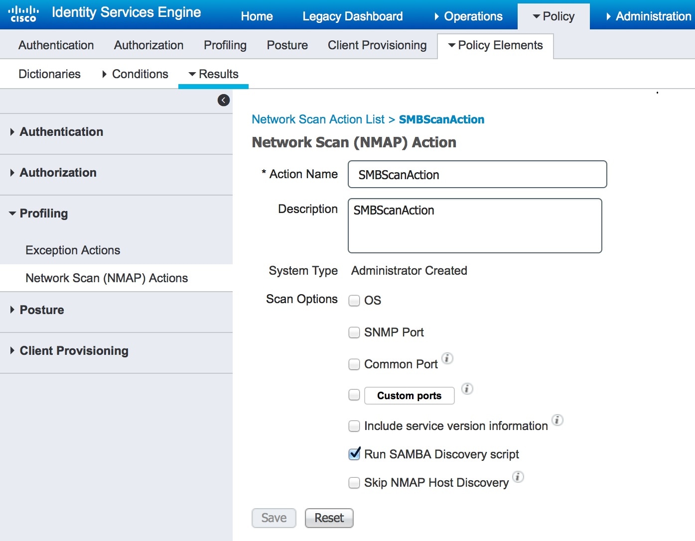
What to do next
You should configure the profiler policy using the SMB scan action.
Configure the Profiler Policy Using the SMB Scan Action
Before you begin
You must create a new profiler policy to scan an endpoint with the SMB scan action. For example, you can scan a Microsoft Workstation by specifying a rule that if the DHCP class identifier contains the MSFT attribute, then a network action should be taken.
Procedure
| Step 1 |
Choose page. |
| Step 2 |
Enter the Name and Description. |
| Step 3 |
In the drop-down, select the scan action (for example, SMBScanAction) that you had created. Network Scan (NMAP) Action
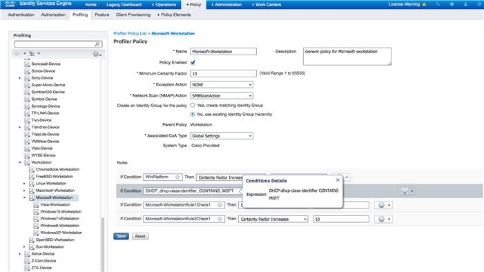 |
What to do next
You should add a new condition using the SMB attribute.
Add a New Condition Using the SMB Attribute
Before you begin
You should create a new profiler policy to scan the version of an endpoint. For example, you can scan for Windows 7 under the Microsoft Workstation parent policy.
Procedure
| Step 1 |
Choose page. |
| Step 2 |
Enter the Name (for example, Windows-7Workstation) and Description. |
| Step 3 |
In the Network Scan (NMAP) Action drop-down, select None. |
| Step 4 |
In the Parent Policy drop-down choose the Microsoft-Workstation policy. 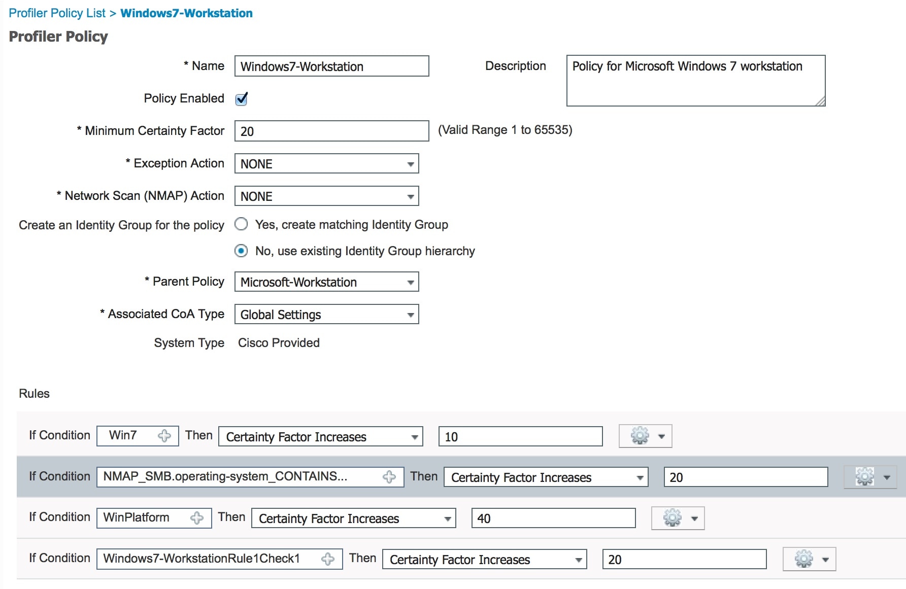 |
Enable File Sharing to Run NMAP SMB Discovery Script
Given below is an example to enable file sharing in Windows OS version 7, to run the NMAP SMB discovery script.
Procedure
| Step 1 |
Choose Control Panel > Network and Internet. |
| Step 2 |
Choose the Network and Sharing Center. |
| Step 3 |
Select Change Advanced Sharing Settings. |
| Step 4 |
Ensure that the Turn on File and Printer Sharing radio button is selected. |
| Step 5 |
Be sure that the Enable File Sharing for Devices That Use 40- or 56-bit Encryption and Turn on Password Protected Sharing radio buttons are selected. |
| Step 6 |
(Optional) Click Save Changes. |
| Step 7 |
Configure the Firewall settings.
|
| Step 8 |
Configure the shared folder.
|
Exclude Subnets from NMAP Scan
You can perform an NMAP scan to identify an endpoint's OS or SNMP port.
When performing the NMAP scan, you can exclude a whole subnet or IP range that should not be scanned by NMAP. You can configure the subnet or IP range in the NMAP Scan Subnet Exclusions page (Work Centers > Profiler > Settings > NMAP Scan Subnet Exclusions). This helps limit the load on your network and saves a considerable amount of time.
For Manual NMAP scan, you can use the Run Manual NMAP Scan page (Work Centers > Profiler > Manual Scans > Manual NMAP Scan > Configure NMAP Scan Subnet Exclusions At) to specify the subnet or IP range.
Manual NMAP Scan Settings
You can perform a manual NMAP scan () using the scan options that are available for automatic NMAP scan. You can choose either the scan options or the predefined ones.
|
Fields |
Usage Guidelines |
|---|---|
|
Node |
Choose the ISE node from which the NMAP scan is run. |
|
Manual Scan Subnet |
Enter the range of subnet IP addresses of endpoints for which you want to run the NMAP scan. |
|
Configure NMAP Scan Subnet Exclusions At |
You will be directed to the page. Specify the IP address and subnet mask that should be excluded. If there is a match, the NMAP scan is not run. |
|
NMAP Scan Subnet |
|
|
Specify Scan Options |
Select the required scan options: OS, SNMP Port, Common Ports, Custom Ports, Include Service Version Information, Run SMB Discovery Script, Skip NMAP Host Discovery. Refer to the Create a New Network Scan Action topic for more information. |
|
Select an Existing NMAP Scan |
Displays the Existing NMAP Scan Actions drop-down that displays the default profiler NMAP scan actions. |
|
Reset to Default Scan Options |
Click the button to restore default settings (all scan options are checked). |
|
Save as NMAP Scan Action |
Enter an action name and a description. |
Run a Manual NMAP Scan
Procedure
| Step 1 |
Choose . |
| Step 2 |
In the Node drop-down, select the ISE node from which you intend to run the NMAP scan. |
| Step 3 |
In the Manual Scan Subnet text box, enter the subnet address whose endpoints you intend to check for open ports. |
| Step 4 |
Select the required Scan Options.
|
| Step 5 |
Click Run Scan. |
Configure Profiler Policies Using the McAfee ePolicy Orchestrator
Cisco ISE profiling services can detect if the McAfee ePolicy Orchestrator (McAfee ePO) client is present on the endpoint. This helps in determining if a given endpoint belongs to your organization.
-
ISE Server
-
McAfee ePO Server
-
McAfee ePO Agent
Cisco ISE provides an in-built NMAP scan action (MCAFeeEPOOrchestratorClientscan) to check if the McAfee agent is running on an endpoint using NMAP McAfee script on the configured port. You can also create new NMAP scan options using the custom ports (for example, 8082). You can configure a new NMAP scan action using the McAfee ePO software by following the steps below:
Procedure
| Step 1 | |
| Step 2 | |
| Step 3 |
Configure profiler policies using the McAfee ePO NMAP scan action. |
Configure the McAfee ePo NMAP Scan Action
Procedure
| Step 1 |
Choose . |
| Step 2 |
Click Add. |
| Step 3 |
Enter the Action Name and Description. |
| Step 4 |
In the Scan Options, check the Custom Ports. |
| Step 5 |
In the Custom Ports dialog box, add the required TCP port. The 8080 TCP port is enabled by default for McAfee ePO. |
| Step 6 |
Check the Include Service Version Information checkbox. |
| Step 7 |
Click Submit. |
What to do next
Configure the McAfee ePO agent.
Configure the McAfee ePO Agent
Procedure
| Step 1 |
In your McAfee ePO server, check the recommended settings to facilitate the communication between the McAfee ePO agent and the ISE server. 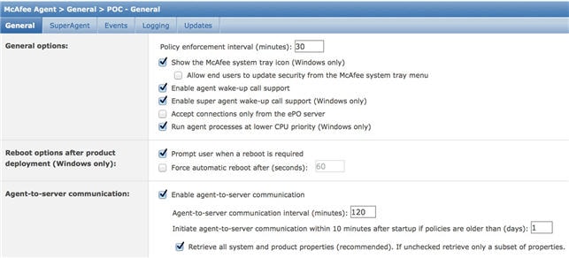 |
| Step 2 |
Verify that the Accept Connections Only From The ePO Server is unchecked. |
What to do next
Configure profiler policies using the McAfee ePO NMAP scan action.
Configure Profiler Policies Using the McAfee ePO NMAP Scan Action
Procedure
| Step 1 |
Choose . |
| Step 2 |
Enter the Name and Description. |
| Step 3 |
In the Network Scan (NMAP) Action drop-down, select the required action (for example, MCAFeeEPOOrchestratorClientscan). |
| Step 4 |
Create the parent profiler policy (for example, Microsoft-Workstation containing a rule to check if the DHCP class identifier contains the MSFT attribute). 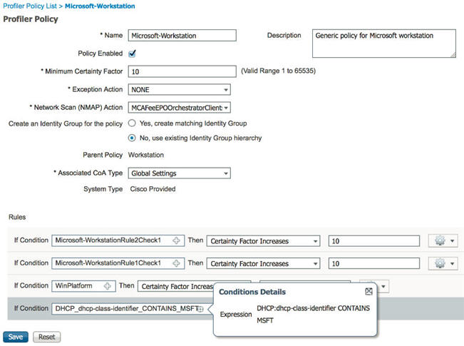 |
| Step 5 |
Create a new policy (for example CorporateDevice) within the parent NMAP McAfee ePO policy (for example, Microsoft-Workstation) to check if the McAfee ePO agent is installed on the endpoint. Endpoints that meet the condition are profiled as corporate devices. You can use the policy to move endpoints profiled with McAfee ePO agent to a new VLAN. 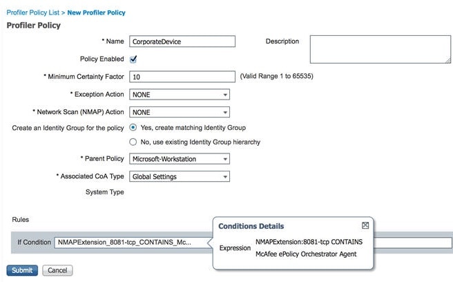 |
Profiler Endpoint Custom Attributes
You can use the Endpoint page to assign attributes to endpoints, besides the attributes that the endpoint gathers from the probe. The endpoint custom attributes can be used in authorization policies to profile endpoints.
You can create a maximum of 100 endpoint custom attributes. The types of endpoint custom attributes supported are: Int, String, Long, Boolean, and Float.
You can add values for the endpoint custom attributes in the page.
Use cases for endpoint custom attributes include, to white list or black list devices based on certain attributes or to assign certain privileges based on the authorization.
Using Endpoint Custom Attributes in Authorization Policy
The endpoint custom attributes section allows you to configure extra attributes. Each definition consists of the attribute and type (String, Int, Boolean, Float, Long). You can profile devices using endpoint custom attributes.
Note |
You must have a plus or higher license to add custom attributes to the endpoints. |
The following steps show how to create an authorization policy using endpoint custom attributes.
Procedure
| Step 1 |
Create the endpoint custom attributes and assign values. |
| Step 2 |
Create an authorization policy using the custom attributes and values.
|
Create a Profiler Condition
Endpoint profiling policies in Cisco ISE allow you to categorize discovered endpoints on your network, and assign them to specific endpoint identity groups. These endpoint profiling policies are made up of profiling conditions that Cisco ISE evaluates to categorize and group endpoints.
Before you begin
To perform the following task, you must be a Super Admin or Policy Admin.
Procedure
| Step 1 |
Choose . |
| Step 2 |
Enter values for the fields as described in the Endpoint Profiling Policies Settings. |
| Step 3 |
Click Submit to save the profiler condition. |
| Step 4 |
Repeat this procedure to create more conditions. |
Endpoint Profiling Policy Rules
You can define a rule that allows you to choose one or more profiling conditions from the library that are previously created and saved in the policy elements library, and to associate an integer value for the certainty factor for each condition, or associate either an exception action or a network scan action for that condition. The exception action or the network scan action is used to trigger the configurable action while Cisco ISE is evaluating the profiling policies with respect to the overall classification of endpoints.
When the rules in a given policy are evaluated separately with an OR operator, the certainty metric for each rule contributes to the overall matching of the endpoint profiles into a specific category of endpoints. If the rules of an endpoint profiling policy match, then the profiling policy and the matched policy are the same for that endpoint when they are dynamically discovered on your network.
Logically Grouped Conditions in Rules
An endpoint profiling policy (profile) contains a single condition or a combination of multiple single conditions that are logically combined using an AND or OR operator, against which you can check, categorize, and group endpoints for a given rule in a policy.
A condition is used to check the collected endpoint attribute value against the value specified in the condition for an endpoint. If you map more than one attribute, you can logically group the conditions, which helps you to categorize endpoints on your network. You can check endpoints against one or more such conditions with a corresponding certainty metric (an integer value that you define) associated with it in a rule or trigger an exception action that is associated to the condition or a network scan action that is associated to the condition.
Certainty Factor
The minimum certainty metric in the profiling policy evaluates the matching profile for an endpoint. Each rule in an endpoint profiling policy has a minimum certainty metric (an integer value) associated to the profiling conditions. The certainty metric is a measure that is added for all the valid rules in an endpoint profiling policy, which measures how each condition in an endpoint profiling policy contributes to improve the overall classification of endpoints.
The certainty metric for each rule contributes to the overall matching of the endpoint profiles into a specific category of endpoints. The certainty metric for all the valid rules are added together to form the matching certainty. It must exceed the minimum certainty factor that is defined in an endpoint profiling policy. By default, the minimum certainty factor for all new profiling policy rules and predefined profiling policies is 10.
Endpoint Profiling Policies Settings
The following table describes the fields in the Endpoint Policies window. The navigation path for this page is: .
|
Field Name |
Usage Guidelines |
|---|---|
|
Name |
Enter the name of the endpoint profiling policy that you want to create. |
|
Description |
Enter the description of the endpoint profiling policy that you want to create. |
|
Policy Enabled |
By default, the Policy Enabled check box is checked to associate a matching profiling policy when you profile an endpoint. When unchecked, the endpoint profiling policy is excluded when you profile an endpoint. |
|
Minimum Certainty Factor |
Enter the minimum value that you want to associate with the profiling policy. The default value is 10. |
|
Exception Action |
Choose an exception action, which you want to associate with the conditions when defining a rule in the profiling policy. The default is NONE. The exception actions are defined in the following location: Policy > Policy Elements > Results > Profiling > Exception Actions. |
|
Network Scan (NMAP) Action |
Choose a network scan action from the list, which you want to associate with the conditions when defining a rule in the profiling policy, if required. The default is NONE. The exception actions are defined in the following location: Policy > Policy Elements > Results > Profiling > Network Scan (NMAP) Actions. |
|
Create an Identity Group for the policy |
Check one of the following options to create an endpoint identity group:
|
|
Yes, create matching Identity Group |
Choose this option to use an existing profiling policy. This option creates a matching identity group for those endpoints and the identity group will be the child of the Profiled endpoint identity group when an endpoint profile matches an existing profiling policy. For example, the Xerox-Device endpoint identity group is created in the Endpoints Identity Groups page when endpoints discovered on your network match the Xerox-Device profile. |
|
No, use existing Identity Group hierarchy |
Check this check box to assign endpoints to the matching parent endpoint identity group using hierarchical construction of profiling policies and identity groups. This option allows you to make use of the endpoint profiling policies hierarchy to assign endpoints to one of the matching parent endpoint identity groups, as well as to the associated endpoint identity groups to the parent identity group. For example, endpoints that match an existing profile are grouped under the appropriate parent endpoint identity group. Here, endpoints that match the Unknown profile are grouped under Unknown, and endpoints that match an existing profile are grouped under the Profiled endpoint identity group. For example,
|
|
Parent Policy |
Choose a parent profiling policy that are defined in the system to which you want to associate the new endpoint profiling policy. You can choose a parent profiling policy from which you can inherit rules and conditions to its child. |
|
Associated CoA Type |
Choose one of the following CoA types that you want to associate with the endpoint profiling policy:
|
|
Rules |
One or more rules that are defined in endpoint profiling policies determine the matching profiling policy for endpoints, which allows you to group endpoints according to their profiles. One or more profiling conditions from the policy elements library are used in rules for validating endpoint attributes and their values for the overall classification. |
|
Conditions |
Click the plus [+] sign to expand the Conditions anchored overlay, and click the minus [-] sign, or click outside the anchored overlay to close it. Click Select Existing Condition from Library or Create New Condition (Advanced Option) . Select Existing Condition from Library---You can define an expression by selecting Cisco predefined conditions from the policy elements library. Create New Condition (Advanced Option)---You can define an expression by selecting attributes from various system or user-defined dictionaries. You can associate one of the following with the profiling conditions:
Choose one of the following predefined settings to associate with the profiling condition:
|
|
Select Existing Condition from Library |
You can do the following:
|
|
Create New Condition (Advance Option) |
You can do the following:
|
Create Endpoint Profiling Policies
You can use the Profiling Policies page to manage endpoint profiling policies that you create as an administrator of Cisco ISE, and also endpoint profiling profiles that are provided by Cisco ISE when deployed.
You can create new profiling policies to profile endpoints by using the following options in the New Profiler Policy page:
-
Policy Enabled
-
Create an Identity Group for the policy to create a matching endpoint identity group or use the endpoint identity group hierarchy
-
Parent Policy
-
Associated CoA Type
Note
When you choose to create an endpoint policy in the Profiling Policies page, do not use the Stop button on your web browsers. This action leads to the following: stops loading the New Profiler Policy page, loads other list pages and the menus within the list pages when you access them, and prevents you from performing operations on all the menus within the list pages except the Filter menus. You might need to log out of Cisco ISE, and then log in again to perform operations on all the menus within the list pages.
You can create a similar characteristic profiling policy by duplicating an endpoint profiling policy through which you can modify an existing profiling policy instead of creating a new profiling policy by redefining all conditions.
Procedure
| Step 1 |
Choose . |
| Step 2 |
Click Add. |
| Step 3 |
Enter a name and description for the new endpoint policy that you want to create. The Policy Enabled check box is checked by default to include the endpoint profiling policy for validation when you profile an endpoint. |
| Step 4 |
Enter a value for the minimum certainty factor within the valid range 1 to 65535. |
| Step 5 |
Click the arrow next to the Exception Action drop-down list to associate an exception action or click the arrow next to the Network Scan (NMAP) Action drop-down list to associate a network scan action. |
| Step 6 |
Choose one of the following options for Create an Identity Group for the policy:
|
| Step 7 |
Click the arrow next to the Parent Policy drop-down list to associate a parent policy to the new endpoint policy. |
| Step 8 |
Choose a CoA type to be associated in the Associated CoA Type drop-down list. |
| Step 9 |
Click in the rule to add conditions and associate an integer value for the certainty factor for each condition or associate either an exception action or a network scan action for that condition for the overall classification of an endpoint. |
| Step 10 |
Click Submit to add an endpoint policy or click the Profiler Policy List link from the New Profiler Policy page to return to the Profiling Policies page. |
Change of Authorization Configuration per Endpoint Profiling Policy
In addition to the global configuration of change of authorization (CoA) types in Cisco ISE, you can also configure to issue a specific type of CoA associated for each endpoint profiling policy.
The global No CoA type configuration overrides each CoA type configured in an endpoint profiling policy. If the global CoA type is set other than the No CoA type, then each endpoint profiling policy is allowed to override the global CoA configuration.
When a CoA is triggered, each endpoint profiling policy can determine the actual CoA type, as follows:
-
General Setting—This is the default setting for all the endpoint profiling policies that issues a CoA per global configuration.
-
No CoA—This setting overrides any global configuration and disables CoA for the profile.
-
Port Bounce—This setting overrides the global Port Bounce and Reauth configuration types, and issues port bounce CoA.
-
Reauth—This setting overrides the global Port Bounce and Reauth configuration types, and issues reauthentication CoA.
Note
If the profiler global CoA configuration is set to Port Bounce (or Reauth), ensure that you configure corresponding endpoint profiling policies with No CoA, the per-policy CoA option so that the BYOD flow does not break for your mobile devices.
See the summary of configuration below combined for all the CoA types and the actual CoA type issued in each case based on the global and endpoint profiling policy settings.
|
Global CoA Type |
Default CoA Type set per Policy |
No coA Type per Policy |
Port Bounce Type per Policy |
Reauth Type per Policy |
|---|---|---|---|---|
|
No CoA |
No CoA |
No CoA |
No CoA |
No CoA |
|
Port Bounce |
Port Bounce |
No CoA |
Port Bounce |
Re-Auth |
|
Reauth |
Reauth |
No CoA |
Port Bounce |
Re-Auth |
Import Endpoint Profiling Policies
You can import endpoint profiling policies from a file in XML by using the same format that you can create in the export function. If you import newly created profiling policies that have parent policies associated, then you must have defined parent policies before you define child policies.
The imported file contains the hierarchy of endpoint profiling policies that contain the parent policy first, then the profile that you imported next along with the rules and checks that are defined in the policy.
Procedure
| Step 1 |
Choose > Profiling Policies. |
| Step 2 |
Click Import. |
| Step 3 |
Click Browse to locate the file that you previously exported and want to import. |
| Step 4 |
Click Submit. |
| Step 5 |
Click the Profiler Policy List link to return to the Profiling Policies page. |
Export Endpoint Profiling Policies
You can export endpoint profiling policies to other Cisco ISE deployments. Or, you can use the XML file as a template for creating your own policies to import. You can also download the file to your system in the default location, which can be used for importing later.
A dialog appears when you want to export endpoint profiling policies, which prompts you to open the profiler_policies.xml with an appropriate application or save it. This is a file in XML format that you can open in a web browser, or in other appropriate applications.
Procedure
| Step 1 |
Choose . |
| Step 2 |
Choose Export, and choose one of the following:
|
| Step 3 |
Click OK to export the endpoint profiling policies in the profiler_policies.xml file. |
Predefined Endpoint Profiling Policies
Cisco ISE includes predefined default profiling policies when Cisco ISE is deployed, and their hierarchical construction allows you to categorize identified endpoints on your network, and assign them to a matching endpoint identity groups. Because endpoint profiling policies are hierarchical, you can find that the Profiling Policies page displays the list of generic (parent) policies for devices and child policies to which their parent policies are associated in the Profiling Policies list page.
The Profiling Policies page displays endpoint profiling policies with their names, type, description and the status, if enabled or not for validation.
The endpoint profiling policy types are classified as follows:
-
Cisco Provided—Endpoint profiling policies that are predefined in Cisco ISE are identified as the Cisco Provided type.
-
Administrator Modified—Endpoint profiling policies are identified as the Administrator Modified type when you modify predefined endpoint profiling policies. Cisco ISE overwrites changes that you have made in the predefined endpoint profiling policies during upgrade.
-
-
Administrator Created—Endpoint profiling policies that you create or when you duplicate Cisco-provided endpoint profiling policies are identified as the Administrator Created type.
We recommend that you create a generic policy (a parent) for a set of endpoints from which its children can inherit the rules and conditions. If an endpoint has to be classified, then the endpoint profile has to first match the parent, and then its descendant (child) policies when you are profiling an endpoint.
For example, Cisco-Device is a generic endpoint profiling policy for all Cisco devices, and other policies for Cisco devices are children of Cisco-Device. If an endpoint has to be classified as a Cisco-IP-Phone 7960, then the endpoint profile for this endpoint has to first match the parent Cisco-Device policy, its child Cisco-IP-Phone policy, and then the Cisco-IP-Phone 7960 profiling policy for better classification.
Note |
Cisco ISE will not overwrite the Administrator Modified policies nor their children policies even if they are still labeled as Cisco Provided. If an Administrator Modified policy is deleted, it reverts back to the previous Cisco Provided policy. Next time when Feed Update happens, all children policies are updated. |
Predefined Endpoint Profiling Policies Overwritten During Upgrade
You can edit existing endpoint profiling policies in the Profiling Policies page. You must also save all your configurations in a copy of the predefined endpoint profiles when you want to modify the predefined endpoint profiling policies.
During an upgrade, Cisco ISE overwrites any configuration that you have saved in the predefined endpoint profiles.
Unable to Delete Endpoint Profiling Policies
You can delete selected or all the endpoint profiling policies in the Profiling Policies page. By default, you can delete all the endpoint profiling policies from the Profiling Policies page. When you select all the endpoint profiling policies and try to delete them in the Profiling Policies page, some of them may not be deleted when the endpoint profiling policies are a parent policy mapped to other endpoint profiling policies or mapped to an authorization policy and a parent policy to other endpoint profiling policies.
For example,
-
You cannot delete Cisco Provided endpoint profiling policies,
-
You cannot delete a parent profile in the Profiling Policies page when an endpoint profile is defined as a parent to other endpoint profiles. For example, Cisco-Device is a parent to other endpoint profiling policies for Cisco devices.
-
You cannot delete an endpoint profile when it is mapped to an authorization policy. For example, Cisco-IP-Phone is mapped to the Profiled Cisco IP Phones authorization policy, and it is a parent to other endpoint profiling policies for Cisco IP Phones.
Predefined Profiling Policies for Draeger Medical Devices
Cisco ISE contains default endpoint profiling policies that include a generic policy for Draeger medical devices, a policy for Draeger-Delta medical device, and a policy for Draeger-M300 medical device. Both the medical devices share ports 2050 and 2150, and therefore you cannot classify the Draeger-Delta and Draeger-M300 medical devices when you are using the default Draeger endpoint profiling policies.
If these Draeger devices share ports 2050 and 2150 in your environment, you must add a rule in addition to checking for the device destination IP address in the default Draeger-Delta and Draeger-M300 endpoint profiling policies so that you can distinquish these medical devices.
Cisco ISE includes the following profiling conditions that are used in the endpoint profiling policies for the Draeger medical devices:
-
Draeger-Delta-PortCheck1 that contains port 2000
-
Draeger-Delta-PortCheck2 that contains port 2050
-
Draeger-Delta-PortCheck3 that contains port 2100
-
Draeger-Delta-PortCheck4 that contains port 2150
-
Draeger-M300PortCheck1 that contains port 1950
-
Draeger-M300PortCheck2 that contains port 2050
-
Draeger-M300PortCheck3 that contains port 2150
Endpoint Profiling Policy for Unknown Endpoints
An endpoint that does not match existing profiles and cannot be profiled in Cisco ISE is an unknown endpoint. An unknown profile is the default system profiling policy that is assigned to an endpoint, where an attribute or a set of attributes collected for that endpoint do not match with existing profiles in Cisco ISE.
An Unknown profile is assigned in the following scenarios:
-
When an endpoint is dynamically discovered in Cisco ISE, and there is no matching endpoint profiling policy for that endpoint, it is assigned to the unknown profile.
-
When an endpoint is statically added in Cisco ISE, and there is no matching endpoint profiling policy for a statically added endpoint, it is assigned to the unknown profile.
If you have statically added an endpoint to your network, the statically added endpoint is not profiled by the profiling service in Cisco ISE. You can change the unknown profile later to an appropriate profile and Cisco ISE will not reassign the profiling policy that you have assigned.
Endpoint Profiling Policy for Statically Added Endpoints
For the endpoint that is statically added to be profiled, the profiling service computes a profile for the endpoint by adding a new MATCHEDPROFILE attribute to the endpoint. The computed profile is the actual profile of an endpoint if that endpoint is dynamically profiled. This allows you to find the mismatch between the computed profile for statically added endpoints and the matching profile for dynamically profiled endpoints.
Endpoint Profiling Policy for Static IP Devices
If you have an endpoint with a statically assigned IP address, you can create a profile for such static IP devices.
You must enable the RADIUS probe or SNMP Query and SNMP Trap probes to profile an endpoint that has a static IP address.
Endpoint Profiling Policy Matching
Cisco ISE always considers a chosen policy for an endpoint that is the matched policy rather than an evaluated policy when the profiling conditions that are defined in one or more rules are met in a profiling policy. Here, the status of static assignment for that endpoint is set to false in the system. But, this can be set to true after it is statically reassigned to an existing profiling policy in the system, by using the static assignment feature during an endpoint editing.
The following apply to the matched policies of endpoints:
-
For statically assigned endpoint, the profiling service computes the MATCHEDPROFILE.
-
For dynamically assigned endpoints, the MATCHEDPROFILEs are identical to the matching endpoint profiles.
You can determine a matching profiling policy for dynamic endpoints using one or more rules that are defined in a profiling policy and assign appropriately an endpoint identity group for categorization.
When an endpoint is mapped to an existing policy, the profiling service searches the hierarchy of profiling policies for the closest parent profile that has a matching group of policies and assigns the endpoint to the appropriate endpoint policy.
Endpoint Profiling Policies Used for Authorization
You can use an endpoint profiling policy in authorization rules, where you can create a new condition to include a check for an endpoint profiling policy as an attribute, and the attribute value assumes the name of the endpoint profiling policy. You can select an endpoint profiling policy from the endpoints dictionary, which includes the following attributes: PostureApplicable, EndPointPolicy, LogicalProfile, and BYODRegistration.
The attribute value for PostureApplicable is auto set based on the operating system. It is set to No for IOS and Android devices since there is no AnyConnect available on those platforms to perform Posture. The value is set as Yes for Mac OSX and Windows devices.
You can define an authorization rule that includes a combination of EndPointPolicy, BYODRegistration, and identity groups.
Endpoint Profiling Policies Grouped into Logical Profiles
A logical profile is a container for a category of profiles or associated profiles, irrespective of Cisco-provided or administrator-created endpoint profiling policies. An endpoint profiling policy can be associated to multiple logical profiles.
You can use the logical profile in an authorization policy condition to help create an overall network access policy for a category of profiles. You can create a simple condition for authorization, which can be included in the authorization rule. The attribute-value pair that you can use in the authorization condition is the logical profile (attribute) and the name of the logical profile (value), which can be found in the EndPoints systems dictionary.
For example, you can create a logical profile for all mobile devices like Android, Apple iPhone, or Blackberry by assigning matching endpoint profiling policies for that category to the logical profile. Cisco ISE contains IP-Phone, a default logical profile for all the IP phones, which includes IP-Phone, Cisco-IP-Phone, Nortel-IP-Phone-2000-Series, and Avaya-IP-Phone profiles.
Create Logical Profiles
You can create a logical profile that you can use to group a category of endpoint profiling policies, which allows you to create an overall category of profiles or associated profiles. You can also remove the endpoint profiling policies from the assigned set moving them back to the available set. For more information about Logical Profiles, see Endpoint Profiling Policies Grouped into Logical Profiles.
Procedure
| Step 1 |
Choose . |
| Step 2 |
Click Add. |
| Step 3 |
Enter a name and description for the new logical profile in the text boxes for Name and Description. |
| Step 4 |
Choose endpoint profiling policies from the Available Policies to assign them in a logical profile. |
| Step 5 |
Click the right arrow to move the selected endpoint profiling policies to the Assigned Policies. |
| Step 6 |
Click Submit. |
Profiling Exception Actions
An exception action is a single configurable action that can be referred to in an endpoint profiling policy, and that is triggered when the exception conditions that are associated with the action are met.
Exception Actions can be any one of the following types:
-
Cisco-provided—You can not delete Cisco-provided exception actions. Cisco ISE triggers the following noneditable profiling exception actions from the system when you want to profile endpoints in Cisco ISE:
-
Authorization Change—The profiling service issues a change of authorization when an endpoint is added or removed from an endpoint identity group that is used by an authorization policy.
-
Endpoint Delete—An exception action is triggered in Cisco ISE and a CoA is issued when an endpoint is deleted from the system in the Endpoints page, or reassigned to the unknown profile from the edit page on a Cisco ISE network.
-
FirstTimeProfiled—An exception action is triggered in Cisco ISE and a CoA is issued when an endpoint is profiled in Cisco ISE for the first time, where the profile of that endpoint changes from an unknown profile to an existing profile but that endpoint is not successfully authenticated on a Cisco ISE network.
-
-
Administrator-created—Cisco ISE triggers profiling exception actions that you create.
Create Exception Actions
You can define and associate one or more exception rules to a single profiling policy. This association triggers an exception action (a single configurable action) when the profiling policy matches and at least one of the exception rules matches in the profiling endpoints in Cisco ISE.
Procedure
| Step 1 |
Choose . |
| Step 2 |
Click Add. |
| Step 3 |
Enter a name and description for the exception action in the text boxes for Name and Description. |
| Step 4 |
Check the CoA Action check box. |
| Step 5 |
Click the Policy Assignment drop-down list to choose an endpoint policy. |
| Step 6 |
Click Submit. |
Create Endpoints with Static Assignments of Policies and Identity Groups
You can create a new endpoint statically by using the MAC address of an endpoint in the Endpoints page. You can also choose an endpoint profiling policy and an identity group in the Endpoints page for static assignment.
The regular and mobile device (MDM) endpoints are displayed in the Endpoints Identities list. In the listing page, columns for attributes like Hostname, Device Type, Device Identifier for MDM endpoints are displayed. Other columns like Static Assignment and Static Group Assignment are not displayed by default.
Note |
You cannot add, edit, delete, import, or export MDM Endpoints using this page. |
Procedure
| Step 1 |
Choose . |
| Step 2 |
Click Add. |
| Step 3 |
Enter the MAC address of an endpoint in hexadecimal format and separated by a colon. |
| Step 4 |
Choose a matching endpoint policy from the Policy Assignment drop-down list to change the static assignment status from dynamic to static. |
| Step 5 |
Check the Static Assignment check box to change the status of static assignment that is assigned to the endpoint from dynamic to static. |
| Step 6 |
Choose an endpoint identity group to which you want to assign the newly created endpoint from the Identity Group Assignment drop-down list. |
| Step 7 |
Check the Static Group Assignment check box to change the dynamic assignment of an endpoint identity group to static. |
| Step 8 |
Click Submit. |
Import Endpoints from CSV Files
Note |
To import endpoint custom attributes, you have to create the same custom attributes as in the CSV file in the page using the correct data types. These attributes have to be prefixed with "CUSTOM." to differentiate them from endpoint attributes. |
There are about 30 attributes that can be imported. The list includes MACAddress, EndPointPolicy, and IdentityGroup. Optional attributes are:
|
Description |
PortalUser |
LastName |
|
PortalUser.GuestType |
PortalUser.FirstName |
EmailAddress |
|
PortalUser.Location |
Device Type |
host-name |
|
PortalUser.GuestStatus |
StaticAssignment |
Location |
|
PortalUser.CreationType |
StaticGroupAssignment |
MDMEnrolled |
|
PortalUser.EmailAddress |
User-Name |
MDMOSVersion |
|
PortalUser.PhoneNumber |
DeviceRegistrationStatus |
MDMServerName |
|
PortalUser.LastName |
AUPAccepted |
MDMServerID |
|
PortalUser.GuestSponsor |
FirstName |
BYODRegistration |
|
CUSTOM.<custom attribute name> |
— |
— |
-
MACAddress
-
MACAddress, EndPointPolicy
-
MACAddress, EndPointPolicy, IdentityGroup
-
MACAddress, EndPointPolicy, IdentityGroup, <List of attributes listed above as optional attributes>
All attribute values, except MAC address, are optional for importing endpoints from a CSV file. If you want to import endpoints without certain values, the values are still separated by the comma.
For example,
-
MAC1, Endpoint Policy1, Endpoint Identity Group1
-
MAC2
-
MAC3, Endpoint Policy3
-
MAC4, , Endpoint Identity Group4
-
MAC5, , Endpoint Identity Group5, MyDescription, MyPortalUser, and so on
Procedure
| Step 1 |
Choose . |
| Step 2 |
Click Import From File. |
| Step 3 |
Click Browse to locate the CSV file that you have already created. |
| Step 4 |
Click Submit. |
Default Import Template Available for Endpoints
You must update the MAC addresses of endpoints, endpoint profiling policies, endpoint identity groups along with any of the optional attribute values you wish to import, and save the file with a new file name. This file can be used to import endpoints. See the header row in the template.csv file that is created when you use the Generate a Template link.
| MAC | EndpointPolicy | IdentityGroup | Other Optional Attributes |
|---|---|---|---|
| 11:11:11:11:11:11 | Android | Profiled | <Empty>/<Value> |
Unknown Endpoints Reprofiled During Import
| MAC Address | Endpoint Profiling Policy Assigned Before Import in Cisco ISE | Endpoint Profiling Policy Assigned After Import in Cisco ISE |
|---|---|---|
| 00:00:00:00:01:02 | Unknown. | Xerox-Device |
| 00:00:00:00:01:03 | Unknown. | Xerox-Device |
| 00:00:00:00:01:04 | Unknown. | Xerox-Device |
| 00:00:00:00:01:05 | If no profile is assigned to an endpoint, then it is assigned to the Unknown profile, and also reprofiled to the matching profile. | Xerox-Device |
Endpoints with Invalid Attributes Not Imported
If any of the endpoints present in the CSV file have invalid attributes, then the endpoints are not imported and an error message is displayed.
For example, if endpoints are assigned to invalid profiles in the file used for import, then they are not imported because there are no matching profiles in Cisco ISE. See below how endpoints are not imported when they are assigned to invalid profiles in the CSV file.
| MAC Address | Endpoint Profiling Policy Assigned Before Import in Cisco ISE | Endpoint Profiling Policy Assigned After Import in Cisco ISE |
|---|---|---|
| 00:00:00:00:01:02 | Unknown. | Xerox-Device |
| 00:00:00:00:01:05 | If an endpoint such as 00:00:00:00:01:05 is assigned to an invalid profile other than the profiles that are available in Cisco ISE, then Cisco ISE displays a warning message that the policy name is invalid and the endpoint will not be imported. | The endpoint is not imported because there is no matching profile in Cisco ISE. |
Import Endpoints from LDAP Server
You can import the MAC addresses, the associated profiles, and the endpoint identity groups of endpoints securely from an LDAP server.
Before you begin
Before you begin to import endpoints, ensure that you have installed the LDAP server.
You have to configure the connection settings and query settings before you can import from an LDAP server. If the connection settings or query settings are configured incorrectly in Cisco ISE, then the “LDAP import failed:” error message appears.
Procedure
| Step 1 |
Choose . |
| Step 2 |
Enter the values for the connection settings. |
| Step 3 |
Enter the values for the query settings. |
| Step 4 |
Click Submit. |
Export Endpoints with Comma-Separated Values File
Note |
To import endpoint custom attributes exported from one deployment to another, you must create the same custom attributes in the page and use the same data type as specified in the original deployment. |
Export All exports all the endpoints in Cisco ISE, whereas Export Selected exports only the endpoints selected by the user. By default, the profiler_endpoints.csv is the CSV file and Microsoft Office Excel is the default application to open the CSV file.
Procedure
| Step 1 |
Choose . |
| Step 2 |
Click Export, and choose one of the following:
|
| Step 3 |
Click OK to save the profiler_endpoints.csv file. |
-
UpdateTime : The last time that the profiler updated the endpoint, due to a change to an endpoint attribute. The value is 0 if there have been no updates since the endpoint session started. It will be blank briefly, during an update.
-
InactivityTime: Time since the endpoint was active.
Identified Endpoints
Cisco ISE displays identified endpoints that connect to your network and use resources on your network in the Endpoints page. An endpoint is typically a network-capable device that connect to your network through wired and wireless network access devices and VPN. Endpoints can be personal computers, laptops, IP phones, smart phones, gaming consoles, printers, fax machines, and so on.
The MAC address of an endpoint, expressed in hexadecimal form, is always the unique representation of an endpoint, but you can also identify an endpoint with a varying set of attributes and the values associated to them, called an attribute-value pair. You can collect a varying set of attributes for endpoints based on the endpoint capability, the capability and configuration of the network access devices and the methods (probes) that you use to collect these attributes.
Dynamically Profiled Endpoints
When endpoints are discovered on your network, they can be profiled dynamically based on the configured profiling endpoint profiling policies, and assigned to the matching endpoint identity groups depending on their profiles.
Statically Profiled Endpoints
An endpoint can be profiled statically when you create an endpoint with its MAC address and associate a profile to it along with an endpoint identity group in Cisco ISE. Cisco ISE does not reassign the profiling policy and the identity group for statically assigned endpoints.
Unknown Endpoints
If you do not have a matching profiling policy for an endpoint, you can assign an unknown profiling policy (Unknown) and the endpoint therefore will be profiled as Unknown. The endpoint profiled to the Unknown endpoint policy requires that you create a profile with an attribute or a set of attributes collected for that endpoint. The endpoint that does not match any profile is grouped within the Unknown endpoint identity group.
Identified Endpoints Locally Stored in Policy Service Nodes Database
Cisco ISE writes identified endpoints locally in the Policy Service node database. After storing endpoints locally in the database, these endpoints are then made available (remote write) in the Administration node database only when significant attributes change in the endpoints, and replicated to the other Policy Service nodes database.
The following are the significant attributes:
-
ip
-
EndPointPolicy
-
MatchedValue
-
StaticAssignment
-
StaticGroupAssignment
-
MatchedPolicyID
-
NmapSubnetScanID
-
PortalUser
-
DeviceRegistrationStatus
-
BYODRegistration
When you change endpoint profile definitions in Cisco ISE, all endpoints have to be reprofiled. A Policy Service node that collects the attributes of endpoints is responsible for reprofiling of those endpoints.
When a Policy Service node starts collecting attributes about an endpoint for which attributes were initially collected by a different Policy Service node, then the endpoint ownership changes to the current Policy Service node. The new Policy Service node will retrieve the latest attributes from the previous Policy Service node and reconcile the collected attributes with those attributes that were already collected.
When a significant attribute changes in the endpoint, attributes of the endpoint are automatically saved in the Administration node database so that you have the latest significant change in the endpoint. If the Policy Service node that owns an endpoint is not available for some reasons, then the Administrator ISE node will reprofile an endpoint that lost the owner and you have to configure a new Policy Service node for such endpoints.
Policy Service Nodes in Cluster
Cisco ISE uses Policy Service node group as a cluster that allows to exchange endpoint attributes when two or more nodes in the cluster collect attributes for the same endpoint. We recommend to create clusters for all Policy Service nodes that reside behind a load balancer.
If a different node other than the current owner receives attributes for the same endpoint, it sends a message across the cluster requesting the latest attributes from the current owner to merge attributes and determine if a change of ownership is needed. If you have not defined a node group in Cisco ISE, it is assumed that all nodes are within one cluster.
There are no changes made to endpoint creation and replication in Cisco ISE. Only the change of ownership for endpoints is decided based on a list of attributes (white list) used for profiling that are built from static attributes and dynamic attributes.
Upon subsequent attributes collection, the endpoint is updated on the Administration node, if anyone of the following attributes changes:
-
ip
-
EndPointPolicy
-
MatchedValue
-
StaticAssignment
-
StaticGroupAssignment
-
MatchedPolicyID
-
NmapSubnetScanID
-
PortalUser
-
DeviceRegistrationStatus
-
BYODRegistration
When an endpoint is edited and saved in the Administration node, the attributes are retrieved from the current owner of the endpoint.
Create Endpoint Identity Groups
Cisco ISE groups endpoints that it discovers in to the corresponding endpoint identity groups. Cisco ISE comes with several system-defined endpoint identity groups. You can also create additional endpoint identity groups from the Endpoint Identity Groups page. You can edit or delete the endpoint identity groups that you have created. You can only edit the description of the system-defined endpoint identity groups; you cannot edit the name of these groups or delete them.
Procedure
| Step 1 |
Choose . |
| Step 2 |
Click Add. |
| Step 3 |
Enter the name for the endpoint identity group that you want to create (do not include spaces in the name of the endpoint identity group). |
| Step 4 |
Enter the description for the endpoint identity group that you want to create. |
| Step 5 |
Click the Parent Group drop-down list to choose an endpoint identity group to which you want to associate the newly created endpoint identity group. |
| Step 6 |
Click Submit. |
Identified Endpoints Grouped in Endpoint Identity Groups
Cisco ISE groups discovered endpoints into their corresponding endpoint identity groups based on the endpoint profiling policies. Profiling policies are hierarchical, and they are applied at the endpoint identify groups level in Cisco ISE. By grouping endpoints to endpoint identity groups, and applying profiling policies to endpoint identity groups, Cisco ISE enables you to determine the mapping of endpoints to the endpoint profiles by checking corresponding endpoint profiling policies.
Cisco ISE creates a set of endpoint identity groups by default, and allows you to create your own identity groups to which endpoints can be assigned dynamically or statically. You can create an endpoint identity group and associate the identity group to one of the system-created identity groups. You can also assign an endpoint that you create statically to any one of the identity groups that exists in the system, and the profiling service cannot reassign the identity group.
Default Endpoint Identity Groups Created for Endpoints
Cisco ISE creates the following five endpoint identity groups by default: Blacklist, GuestEndpoints, Profiled, RegisteredDevices, and Unknown. In addition, it creates two more identity groups, such as Cisco-IP-Phone and Workstation, which are associated to the Profiled (parent) identity group. A parent group is the default identity group that exists in the system.
Cisco ISE creates the following endpoint identity groups:
-
Blacklist—This endpoint identity group includes endpoints that are statically assigned to this group in Cisco ISE and endpoints that are blacklisted in the device registration portal. An authorization profile can be defined in Cisco ISE to permit, or deny network access to endpoints in this group.
-
GuestEndpoints—This endpoint identity group includes endpoints that are used by guest users.
-
Profiled—This endpoint identity group includes endpoints that match endpoint profiling policies except Cisco IP phones and workstations in Cisco ISE.
-
RegisteredDevices—This endpoint identity group includes endpoints, which are registered devices that are added by an employee through the devices registration portal. The profiling service continues to profile these devices normally when they are assigned to this group. Endpoints are statically assigned to this group in Cisco ISE, and the profiling service cannot reassign them to any other identity group. These devices will appear like any other endpoint in the endpoints list. You can edit, delete, and blacklist these devices that you added through the device registration portal from the endpoints list in the Endpoints page in Cisco ISE. Devices that you have blacklisted in the device registration portal are assigned to the Blacklist endpoint identity group, and an authorization profile that exists in Cisco ISE redirects blacklisted devices to an URL, which displays “Unauthorised Network Access”, a default portal page to the blacklisted devices.
-
Unknown—This endpoint identity group includes endpoints that do not match any profile in Cisco ISE.
In addition to the above system created endpoint identity groups, Cisco ISE creates the following endpoint identity groups, which are associated to the Profiled identity group:
-
Cisco-IP-Phone—An identity group that contains all the profiled Cisco IP phones on your network.
-
Workstation—An identity group that contains all the profiled workstations on your network.
Endpoint Identity Groups Created for Matched Endpoint Profiling Policies
If you have an endpoint policy that matches an existing policy, then the profiling service can create a matching endpoint identity group. This identity group becomes the child of the Profiled endpoint identity group. When you create an endpoint policy, you can check the Create Matching Identity Group check box in the Profiling Policies page to create a matching endpoint identity group. You cannot delete the matching identity group unless the mapping of the profile is removed.
Add Static Endpoints in Endpoint Identity Groups
You can add or remove statically added endpoints in any endpoint identity group.
You can add endpoints from the Endpoints widget only to a specific identity group. If you add an endpoint to the specific endpoint identity group, then the endpoint is moved from the endpoint identity group where it was dynamically grouped earlier.
Upon removal from the endpoint identity group where you recently added an endpoint, the endpoint is reprofiled back to the appropriate identity group. You do not delete endpoints from the system but only remove them from the endpoint identity group.
Procedure
| Step 1 |
Choose . |
| Step 2 |
Choose an endpoint identity group, and click Edit. |
| Step 3 |
Click Add. |
| Step 4 |
Choose an endpoint in the Endpoints widget to add the selected endpoint in the endpoint identity group. |
| Step 5 |
Click the Endpoint Group List link to return to the Endpoint Identity Groups page. |
Dynamic Endpoints Reprofiled After Adding or Removing in Identity Groups
If an endpoint identity group assignment is not static, then endpoints are reprofiled after you add or remove them from an endpoint identity group. Endpoints that are identified dynamically by the ISE profiler appear in appropriate endpoint identity groups. If you remove dynamically added endpoints from an endpoint identity group, Cisco ISE displays a message that you have successfully removed endpoints from the identity group but reprofiles them back in the endpoint identity group.
Endpoint Identity Groups Used in Authorization Rules
You can effectively use endpoint identity groups in the authorization policies to provide appropriate network access privileges to the discovered endpoints. For example, an authorization rule for all types of Cisco IP Phones is available by default in Cisco ISE in the following location: .
You must ensure that the endpoint profiling policies are either standalone policies (not a parent to other endpoint profiling policies), or their parent policies of the endpoint profiling policies are not disabled.
Profiler Feed Service
Profiler conditions, exception actions, and NMAP scan actions are classified as Cisco-provided or administrator-created, as shown in the System Type attribute. Endpoint profiling policies are classified as Cisco-provided, administrator-created, or administrator- modified. These classifications are shown in the System Type attribute.
You can perform different operations on the profiler conditions, exception actions, NMAP scan actions, and endpoint profiling policies depending on the System Type attribute. You cannot edit or delete Cisco-provided conditions, exception actions, and nmap scan actions. You can not delete Endpoint policies that are provided by Cisco. When you edit policies, they are called administrator-modified. When the feed service updates policies, the administrator-modified policies are replaced by the up-to-date version of the Cisco-provided policy that it was based on.
You can retrieve new and updated endpoint profiling policies and the updated OUI database from the Cisco feed server. You must have a subscription to Cisco ISE. You can also receive e-mail notifications about applied, success, and failure messages. You can send the anonymous information back to Cisco about feed service actions, which helps Cisco improve the feed service.
The OUI database contains the MAC OUIs assigned to vendors. The OUI list is available here: http://standards.ieee.org/develop/regauth/oui/oui.txt
Cisco ISE downloads policies and OUI database updates every day at 1:00 A.M of the local Cisco ISE server time zone. Cisco ISE automatically applies these downloaded feed server policies, and stores the the changes so that you can revert to the previous state. When you revert to a previous state, the new endpoint profiling policies are removed and updated endpoint profiling policies are reverted to the previous state. In addition, the profiler feed service is automatically disabled.
You can also update the feed services manually in offline mode. You can download the updates manually by using this option if you cannot connect your ISE deployments to Cisco feed service.
Note |
Updates from the Feed Service are not allowed after the license goes Out of Compliance (OOC) for 45 days within a 60-day window period. The license is out of compliance when it has expired, or when the usage exceeds the allowed number of sessions. |
Configure Profiler Feed Service
The Profiler Feed Service retrieves new and updated endpoint profiling policies and MAC OUI database updates from the Cisco Feed server. If the Feed Service is unavailable or other errors have occurred, it is reported in the Operations Audit report.
You can configure Cisco ISE to send anonymous feed service usage report back to Cisco, which sends the following information to Cisco:
-
Hostname - Cisco ISE hostname
-
MaxCount - Total number of endpoints
-
ProfiledCount - Profiled endpoints count
-
UnknownCount - Unknown endpoints count
-
MatchSystemProfilesCount - Cisco Provided profiles count
-
UserCreatedProfiles - User created profiles count
You can change the CoA type in a Cisco-provided profiling policy. When the feed service updates that policy, the CoA type will not be changed, but the rest of that policy's attributes will be still be updated.
Before you begin
The Profiler feed service can only be configured from the Cisco ISE Admin portal in a distributed deployment or in a standalone ISE node.
Set up a Simple Mail Transfer Protocol (SMTP) server if you plan to send e-mail notifications from the Admin portal about feed updates().
To update the Feed Services online:
Procedure
| Step 1 |
Choose , and check if Verisign Class 3 Public Primary Certification Authority and Verisign Class 3 Server CA - G3 are enabled. |
| Step 2 |
Choose . You can also access the option in the
page.
|
| Step 3 |
Click the Online Subscription Update tab. |
| Step 4 |
Click the Test Feed Service Connection button to verify that there is a connection to the Cisco Feed Service, and that the certificate is valid. |
| Step 5 |
Check the Enable Online Subscription Update check box. |
| Step 6 |
Enter time in HH:MM format (local time zone of the Cisco ISE server). By default, Cisco ISE feed service is scheduled at 1.00 AM every day. |
| Step 7 |
Check the Notify administrator when download occurs check box and enter your e-mail address in the Administrator email address text box. Check the Provide Cisco anonymous information to help improve profiling accuracy check box, if you want to allow Cisco ISE to collect non-sensitive information (that will be used to provide better services and additional features in forthcoming releases). |
| Step 8 |
Click Save. |
| Step 9 |
Click Update Now. Instructs Cisco ISE to contact Cisco feed server for new and updated profiles created since the last feed service update. This re-profiles all endpoints in the system, which may cause an increase the load on the system. Due to updated endpoint profiling policies, there may be changes in the authorization policy for some endpoints that are currently connected to Cisco ISE. The Update Now button is disabled when you update new and updated profiles created since the last feed service and enabled only after the download is completed. You must navigate away from the profiler feed service Configuration page and return to this page. |
Configure Profiler Feed Services Offline
You can update the feed services offline when Cisco ISE is not directly connected to the Cisco feed server. You can download the offline update package from the Cisco feed server and upload it to Cisco ISE using the offline feed update. You can also set email notifications about new policies that are added to the feed server.
Configuring the profiler feed services offline involves the following tasks:
-
Download Offline Update Package
-
Apply Offline Feed Updates
Download Offline Update Package
To download offline update package:
Procedure
| Step 1 |
Choose . You can also access the option in the
page.
|
| Step 2 |
Click the Offline Manual Update tab. |
| Step 3 |
Click Download Updated Profile Policies link. You will be redirected to Feed Service Partner Portal. You can
also go to
https://ise.cisco.com/partner/ from your browser, to go to
the feed service partner portal directly.
|
| Step 4 |
If you are a first time user, accept the terms and agreements. An email
will be triggered to Feed Services administrator to approve your request. Upon
approval, you will receive a confirmation email.
|
| Step 5 |
Login to the partner portal using your Cisco.com credentials. |
| Step 6 |
Choose Offline Feed > Download Package . |
| Step 7 |
Click Generate Package . |
| Step 8 |
Click the Click to View the Offline Update Package contents link to view all the profiles and OUIs that are included in the generated package.
|
| Step 9 |
Click Download Package and save the file to your local system. You can
upload the saved file to Cisco ISE server to apply the feed updates in the
downloaded package.
|
Apply Offline Feed Updates
To apply the downloaded offline feed updates:
Before you begin
You must have downloaded the offline update package before applying the feed updates.
Procedure
| Step 1 |
Choose . You can also access the option in the
page.
|
| Step 2 |
Click the Offline Manual Update tab. |
| Step 3 |
Click Browse and choose the downloaded profiler feed package. |
| Step 4 |
Click Apply Update . |
Configure Email Notifications for Profile and OUI Updates
You can configure your email address to receive notifications on profile and OUI updates.
To configure email notifications:
Procedure
| Step 1 |
Perform Step 1 through Step 5 in the Download Offline Update Package section to go to the Feed Service Partner Portal. |
| Step 2 |
Choose Offline Feed > Email Preferences. |
| Step 3 |
Check the Enable Notifications checkbox to receive notifications. |
| Step 4 |
Choose the number of days from the days drop-down list to set the frequency in which you want to receive the notifications on new updates. |
| Step 5 |
Enter the e-mail address/addresses and click Save . |
Undo Feed Updates
You can revert endpoint profiling policies that were updated in the previous update and remove endpoint profiling policies and OUIs that are newly added through the previous update of the profiler feed service .
An endpoint profiling policy, if modified after an update from the feed server is not changed in the system.
Procedure
| Step 1 |
Choose . |
| Step 2 |
Click Go to Update Report Page if you want to view the configuration changes made in the Change Configuration Audit report. |
| Step 3 |
Click Undo Latest. |
Profiler Reports
Cisco ISE provides you with various reports on endpoint profiling, and troubleshooting tools that you can use to manage your network. You can generate reports for historical as well as current data. You may be able to drill down on a part of the report to view more details. For large reports, you can also schedule reports and download them in various formats.
You can run the following reports for endpoints from Operations > Reports > Endpoints and Users:
-
Endpoint Session History
-
Profiled Endpoint Summary
-
Endpoint Profile Changes
-
Top Authorizations by Endpoint
-
Registered Endpoints
Detect Anomalous Behavior of Endpoints
Cisco ISE protects your network from the illegitimate use of a MAC address. ISE detects the endpoints involved in MAC address spoofing and allows you to restrict the permission of the suspicious endpoints.
The following are the two options in the profiler configuration page for Anomalous Behavior:
-
Enable Anomalous Behavior Detection
-
Enable Anomalous Behavior Enforcement
If you enable Anomalous Behavior detection, Cisco ISE probes for data, and checks for any contradiction to the existing data with respect to changes in attributes related to NAS-Port-Type, DHCP Class Identifier, and Endpoint Policy. If so, an attribute called AnomalousBehavior set to true is added to the endpoint which helps you to filter and view the endpoints in the Visibility Context page. Audit logs are also generated for the respective MAC address.
When anomalous behavior detection is enabled, Cisco ISE checks if the following attributes of existing endpoints have changed:
-
Port-Type—Determines if the access method of an endpoint has changed. This only applies when the same MAC address that is connected via Wired Dot1x has been used for Wireless Dot1x and visa-versa.
-
DHCP Class Identifier—Determines whether the type of client or vendor of an endpoint has changed. This only applies when DHCP Class identifier attribute is populated with a certain value and is then changed to another value. If an endpoint is configured with a static IP, the DHCP Class Identifier attribute is empty in Cisco ISE. Later on, if another device spoofs the MAC address of this endpoint and uses DHCP, the Class Identifier changes from an empty value to a specific string. This will not trigger anomalous behavior detection.
-
Endpoint Policy—Determines if there are significant profile changes. This only applies when the profile of an endpoint changes from a “Phone” or “Printer” to a “Workstation”.
If you enable Anomalous Behavior Enforcement, a CoA is issued upon detection of the anomalous Behavior , which can be used to re-authorize the suspicious endpoints, based on the authorization rules configured in the Profiler Configuration page.
To set the authorization policy rules for endpoints with anomalous Behavior, see .
Set Authorization Policy Rules for Endpoints with Anomalous Behavior
You can choose the action to be taken against any endpoint with anomalous Behavior by setting the corresponding rules on the Authorization Policy page.
Procedure
| Step 1 |
Choose Policy > Policy Sets. |
| Step 2 |
Click the arrow icon |
| Step 3 |
From the Actions column on any row, click the cog icon and then from the drop-down list, insert a new authorization rule by selecting any of the insert or duplicate options, as necessary. A new row appears in the Policy Sets table.
|
| Step 4 |
Enter the Rule Name. |
| Step 5 |
From the Conditions column, click the (+) symbol. |
| Step 6 |
Create the required conditions in the Conditions Studio Page. In the Editor section, click the Click To Add an Attribute text box, and select the required Dictionary and Attribute (for example, Endpoints.AnomalousBehaviorEqualsTrue). You can also drag and drop a Library condition to the Click To Add An Attribute text box. |
| Step 7 |
Click Use to set the authorization policy rules for endpoints with anomalous behavior. |
| Step 8 |
Click Done. |
 from the
 View Endpoints with Anomalous Behavior
-
Click Anomalous Behavior from Home > Summary > Metrics. This action opens a new tab with Anomalous Behaviour column in the lower pane of the page.
-
Choose Context Visibility > Endpoints > Endpoint Classification. You can view the Anomalous Behaviour column in the lower pane of the page.
-
You can create a new Anomalous Behavior column in Authentication view or Compromised Endpoints view in the Context Visibility page as explained in the following steps:
Procedure
| Step 1 |
Choose Context Visibility > Endpoints > Authentication or Context Visibility > Endpoints > Compromised Endpoints. |
| Step 2 |
Click the Settings icon in the lower pane of the page and check Anomalous Behavior checkbox.. |
| Step 3 |
Click Go. You can
view the Anomalous Behavior column in the Authentication or Compromised
Endpoints View.
|
Create Endpoints with Static Assignments of Policies and Identity Groups
You can create a new endpoint statically by using the MAC address of an endpoint in the Endpoints page. You can also choose an endpoint profiling policy and an identity group in the Endpoints page for static assignment.
The regular and mobile device (MDM) endpoints are displayed in the Endpoints Identities list. In the listing page, columns for attributes like Hostname, Device Type, Device Identifier for MDM endpoints are displayed. Other columns like Static Assignment and Static Group Assignment are not displayed by default.
Note |
You cannot add, edit, delete, import, or export MDM Endpoints using this page. |
Procedure
| Step 1 |
Choose . |
| Step 2 |
Click Add. |
| Step 3 |
Enter the MAC address of an endpoint in hexadecimal format and separated by a colon. |
| Step 4 |
Choose a matching endpoint policy from the Policy Assignment drop-down list to change the static assignment status from dynamic to static. |
| Step 5 |
Check the Static Assignment check box to change the status of static assignment that is assigned to the endpoint from dynamic to static. |
| Step 6 |
Choose an endpoint identity group to which you want to assign the newly created endpoint from the Identity Group Assignment drop-down list. |
| Step 7 |
Check the Static Group Assignment check box to change the dynamic assignment of an endpoint identity group to static. |
| Step 8 |
Click Submit. |
Import Endpoints from CSV Files
Note |
To import endpoint custom attributes, you have to create the same custom attributes as in the CSV file in the page using the correct data types. These attributes have to be prefixed with "CUSTOM." to differentiate them from endpoint attributes. |
There are about 30 attributes that can be imported. The list includes MACAddress, EndPointPolicy, and IdentityGroup. Optional attributes are:
|
Description |
PortalUser |
LastName |
|
PortalUser.GuestType |
PortalUser.FirstName |
EmailAddress |
|
PortalUser.Location |
Device Type |
host-name |
|
PortalUser.GuestStatus |
StaticAssignment |
Location |
|
PortalUser.CreationType |
StaticGroupAssignment |
MDMEnrolled |
|
PortalUser.EmailAddress |
User-Name |
MDMOSVersion |
|
PortalUser.PhoneNumber |
DeviceRegistrationStatus |
MDMServerName |
|
PortalUser.LastName |
AUPAccepted |
MDMServerID |
|
PortalUser.GuestSponsor |
FirstName |
BYODRegistration |
|
CUSTOM.<custom attribute name> |
— |
— |
-
MACAddress
-
MACAddress, EndPointPolicy
-
MACAddress, EndPointPolicy, IdentityGroup
-
MACAddress, EndPointPolicy, IdentityGroup, <List of attributes listed above as optional attributes>
All attribute values, except MAC address, are optional for importing endpoints from a CSV file. If you want to import endpoints without certain values, the values are still separated by the comma.
For example,
-
MAC1, Endpoint Policy1, Endpoint Identity Group1
-
MAC2
-
MAC3, Endpoint Policy3
-
MAC4, , Endpoint Identity Group4
-
MAC5, , Endpoint Identity Group5, MyDescription, MyPortalUser, and so on
Procedure
| Step 1 |
Choose . |
| Step 2 |
Click Import From File. |
| Step 3 |
Click Browse to locate the CSV file that you have already created. |
| Step 4 |
Click Submit. |
Default Import Template Available for Endpoints
You must update the MAC addresses of endpoints, endpoint profiling policies, endpoint identity groups along with any of the optional attribute values you wish to import, and save the file with a new file name. This file can be used to import endpoints. See the header row in the template.csv file that is created when you use the Generate a Template link.
| MAC | EndpointPolicy | IdentityGroup | Other Optional Attributes |
|---|---|---|---|
| 11:11:11:11:11:11 | Android | Profiled | <Empty>/<Value> |
Unknown Endpoints Reprofiled During Import
| MAC Address | Endpoint Profiling Policy Assigned Before Import in Cisco ISE | Endpoint Profiling Policy Assigned After Import in Cisco ISE |
|---|---|---|
| 00:00:00:00:01:02 | Unknown. | Xerox-Device |
| 00:00:00:00:01:03 | Unknown. | Xerox-Device |
| 00:00:00:00:01:04 | Unknown. | Xerox-Device |
| 00:00:00:00:01:05 | If no profile is assigned to an endpoint, then it is assigned to the Unknown profile, and also reprofiled to the matching profile. | Xerox-Device |
Endpoints with Invalid Attributes Not Imported
If any of the endpoints present in the CSV file have invalid attributes, then the endpoints are not imported and an error message is displayed.
For example, if endpoints are assigned to invalid profiles in the file used for import, then they are not imported because there are no matching profiles in Cisco ISE. See below how endpoints are not imported when they are assigned to invalid profiles in the CSV file.
| MAC Address | Endpoint Profiling Policy Assigned Before Import in Cisco ISE | Endpoint Profiling Policy Assigned After Import in Cisco ISE |
|---|---|---|
| 00:00:00:00:01:02 | Unknown. | Xerox-Device |
| 00:00:00:00:01:05 | If an endpoint such as 00:00:00:00:01:05 is assigned to an invalid profile other than the profiles that are available in Cisco ISE, then Cisco ISE displays a warning message that the policy name is invalid and the endpoint will not be imported. | The endpoint is not imported because there is no matching profile in Cisco ISE. |
Import Endpoints from LDAP Server
You can import the MAC addresses, the associated profiles, and the endpoint identity groups of endpoints securely from an LDAP server.
Before you begin
Before you begin to import endpoints, ensure that you have installed the LDAP server.
You have to configure the connection settings and query settings before you can import from an LDAP server. If the connection settings or query settings are configured incorrectly in Cisco ISE, then the “LDAP import failed:” error message appears.
Procedure
| Step 1 |
Choose . |
| Step 2 |
Enter the values for the connection settings. |
| Step 3 |
Enter the values for the query settings. |
| Step 4 |
Click Submit. |
Export Endpoints with Comma-Separated Values File
Note |
To import endpoint custom attributes exported from one deployment to another, you must create the same custom attributes in the page and use the same data type as specified in the original deployment. |
Export All exports all the endpoints in Cisco ISE, whereas Export Selected exports only the endpoints selected by the user. By default, the profiler_endpoints.csv is the CSV file and Microsoft Office Excel is the default application to open the CSV file.
Procedure
| Step 1 |
Choose . |
| Step 2 |
Click Export, and choose one of the following:
|
| Step 3 |
Click OK to save the profiler_endpoints.csv file. |
-
UpdateTime : The last time that the profiler updated the endpoint, due to a change to an endpoint attribute. The value is 0 if there have been no updates since the endpoint session started. It will be blank briefly, during an update.
-
InactivityTime: Time since the endpoint was active.
Identified Endpoints
Cisco ISE displays identified endpoints that connect to your network and use resources on your network in the Endpoints page. An endpoint is typically a network-capable device that connect to your network through wired and wireless network access devices and VPN. Endpoints can be personal computers, laptops, IP phones, smart phones, gaming consoles, printers, fax machines, and so on.
The MAC address of an endpoint, expressed in hexadecimal form, is always the unique representation of an endpoint, but you can also identify an endpoint with a varying set of attributes and the values associated to them, called an attribute-value pair. You can collect a varying set of attributes for endpoints based on the endpoint capability, the capability and configuration of the network access devices and the methods (probes) that you use to collect these attributes.
Dynamically Profiled Endpoints
When endpoints are discovered on your network, they can be profiled dynamically based on the configured profiling endpoint profiling policies, and assigned to the matching endpoint identity groups depending on their profiles.
Statically Profiled Endpoints
An endpoint can be profiled statically when you create an endpoint with its MAC address and associate a profile to it along with an endpoint identity group in Cisco ISE. Cisco ISE does not reassign the profiling policy and the identity group for statically assigned endpoints.
Unknown Endpoints
If you do not have a matching profiling policy for an endpoint, you can assign an unknown profiling policy (Unknown) and the endpoint therefore will be profiled as Unknown. The endpoint profiled to the Unknown endpoint policy requires that you create a profile with an attribute or a set of attributes collected for that endpoint. The endpoint that does not match any profile is grouped within the Unknown endpoint identity group.
Identified Endpoints Locally Stored in Policy Service Nodes Database
Cisco ISE writes identified endpoints locally in the Policy Service node database. After storing endpoints locally in the database, these endpoints are then made available (remote write) in the Administration node database only when significant attributes change in the endpoints, and replicated to the other Policy Service nodes database.
The following are the significant attributes:
-
ip
-
EndPointPolicy
-
MatchedValue
-
StaticAssignment
-
StaticGroupAssignment
-
MatchedPolicyID
-
NmapSubnetScanID
-
PortalUser
-
DeviceRegistrationStatus
-
BYODRegistration
When you change endpoint profile definitions in Cisco ISE, all endpoints have to be reprofiled. A Policy Service node that collects the attributes of endpoints is responsible for reprofiling of those endpoints.
When a Policy Service node starts collecting attributes about an endpoint for which attributes were initially collected by a different Policy Service node, then the endpoint ownership changes to the current Policy Service node. The new Policy Service node will retrieve the latest attributes from the previous Policy Service node and reconcile the collected attributes with those attributes that were already collected.
When a significant attribute changes in the endpoint, attributes of the endpoint are automatically saved in the Administration node database so that you have the latest significant change in the endpoint. If the Policy Service node that owns an endpoint is not available for some reasons, then the Administrator ISE node will reprofile an endpoint that lost the owner and you have to configure a new Policy Service node for such endpoints.
Policy Service Nodes in Cluster
Cisco ISE uses Policy Service node group as a cluster that allows to exchange endpoint attributes when two or more nodes in the cluster collect attributes for the same endpoint. We recommend to create clusters for all Policy Service nodes that reside behind a load balancer.
If a different node other than the current owner receives attributes for the same endpoint, it sends a message across the cluster requesting the latest attributes from the current owner to merge attributes and determine if a change of ownership is needed. If you have not defined a node group in Cisco ISE, it is assumed that all nodes are within one cluster.
There are no changes made to endpoint creation and replication in Cisco ISE. Only the change of ownership for endpoints is decided based on a list of attributes (white list) used for profiling that are built from static attributes and dynamic attributes.
Upon subsequent attributes collection, the endpoint is updated on the Administration node, if anyone of the following attributes changes:
-
ip
-
EndPointPolicy
-
MatchedValue
-
StaticAssignment
-
StaticGroupAssignment
-
MatchedPolicyID
-
NmapSubnetScanID
-
PortalUser
-
DeviceRegistrationStatus
-
BYODRegistration
When an endpoint is edited and saved in the Administration node, the attributes are retrieved from the current owner of the endpoint.
Create Endpoint Identity Groups
Cisco ISE groups endpoints that it discovers in to the corresponding endpoint identity groups. Cisco ISE comes with several system-defined endpoint identity groups. You can also create additional endpoint identity groups from the Endpoint Identity Groups page. You can edit or delete the endpoint identity groups that you have created. You can only edit the description of the system-defined endpoint identity groups; you cannot edit the name of these groups or delete them.
Procedure
| Step 1 |
Choose . |
| Step 2 |
Click Add. |
| Step 3 |
Enter the name for the endpoint identity group that you want to create (do not include spaces in the name of the endpoint identity group). |
| Step 4 |
Enter the description for the endpoint identity group that you want to create. |
| Step 5 |
Click the Parent Group drop-down list to choose an endpoint identity group to which you want to associate the newly created endpoint identity group. |
| Step 6 |
Click Submit. |
Identified Endpoints Grouped in Endpoint Identity Groups
Cisco ISE groups discovered endpoints into their corresponding endpoint identity groups based on the endpoint profiling policies. Profiling policies are hierarchical, and they are applied at the endpoint identify groups level in Cisco ISE. By grouping endpoints to endpoint identity groups, and applying profiling policies to endpoint identity groups, Cisco ISE enables you to determine the mapping of endpoints to the endpoint profiles by checking corresponding endpoint profiling policies.
Cisco ISE creates a set of endpoint identity groups by default, and allows you to create your own identity groups to which endpoints can be assigned dynamically or statically. You can create an endpoint identity group and associate the identity group to one of the system-created identity groups. You can also assign an endpoint that you create statically to any one of the identity groups that exists in the system, and the profiling service cannot reassign the identity group.
Default Endpoint Identity Groups Created for Endpoints
Cisco ISE creates the following five endpoint identity groups by default: Blacklist, GuestEndpoints, Profiled, RegisteredDevices, and Unknown. In addition, it creates two more identity groups, such as Cisco-IP-Phone and Workstation, which are associated to the Profiled (parent) identity group. A parent group is the default identity group that exists in the system.
Cisco ISE creates the following endpoint identity groups:
-
Blacklist—This endpoint identity group includes endpoints that are statically assigned to this group in Cisco ISE and endpoints that are blacklisted in the device registration portal. An authorization profile can be defined in Cisco ISE to permit, or deny network access to endpoints in this group.
-
GuestEndpoints—This endpoint identity group includes endpoints that are used by guest users.
-
Profiled—This endpoint identity group includes endpoints that match endpoint profiling policies except Cisco IP phones and workstations in Cisco ISE.
-
RegisteredDevices—This endpoint identity group includes endpoints, which are registered devices that are added by an employee through the devices registration portal. The profiling service continues to profile these devices normally when they are assigned to this group. Endpoints are statically assigned to this group in Cisco ISE, and the profiling service cannot reassign them to any other identity group. These devices will appear like any other endpoint in the endpoints list. You can edit, delete, and blacklist these devices that you added through the device registration portal from the endpoints list in the Endpoints page in Cisco ISE. Devices that you have blacklisted in the device registration portal are assigned to the Blacklist endpoint identity group, and an authorization profile that exists in Cisco ISE redirects blacklisted devices to an URL, which displays “Unauthorised Network Access”, a default portal page to the blacklisted devices.
-
Unknown—This endpoint identity group includes endpoints that do not match any profile in Cisco ISE.
In addition to the above system created endpoint identity groups, Cisco ISE creates the following endpoint identity groups, which are associated to the Profiled identity group:
-
Cisco-IP-Phone—An identity group that contains all the profiled Cisco IP phones on your network.
-
Workstation—An identity group that contains all the profiled workstations on your network.
Endpoint Identity Groups Created for Matched Endpoint Profiling Policies
If you have an endpoint policy that matches an existing policy, then the profiling service can create a matching endpoint identity group. This identity group becomes the child of the Profiled endpoint identity group. When you create an endpoint policy, you can check the Create Matching Identity Group check box in the Profiling Policies page to create a matching endpoint identity group. You cannot delete the matching identity group unless the mapping of the profile is removed.
Add Static Endpoints in Endpoint Identity Groups
You can add or remove statically added endpoints in any endpoint identity group.
You can add endpoints from the Endpoints widget only to a specific identity group. If you add an endpoint to the specific endpoint identity group, then the endpoint is moved from the endpoint identity group where it was dynamically grouped earlier.
Upon removal from the endpoint identity group where you recently added an endpoint, the endpoint is reprofiled back to the appropriate identity group. You do not delete endpoints from the system but only remove them from the endpoint identity group.
Procedure
| Step 1 |
Choose . |
| Step 2 |
Choose an endpoint identity group, and click Edit. |
| Step 3 |
Click Add. |
| Step 4 |
Choose an endpoint in the Endpoints widget to add the selected endpoint in the endpoint identity group. |
| Step 5 |
Click the Endpoint Group List link to return to the Endpoint Identity Groups page. |
Dynamic Endpoints Reprofiled After Adding or Removing in Identity Groups
If an endpoint identity group assignment is not static, then endpoints are reprofiled after you add or remove them from an endpoint identity group. Endpoints that are identified dynamically by the ISE profiler appear in appropriate endpoint identity groups. If you remove dynamically added endpoints from an endpoint identity group, Cisco ISE displays a message that you have successfully removed endpoints from the identity group but reprofiles them back in the endpoint identity group.
Endpoint Identity Groups Used in Authorization Rules
You can effectively use endpoint identity groups in the authorization policies to provide appropriate network access privileges to the discovered endpoints. For example, an authorization rule for all types of Cisco IP Phones is available by default in Cisco ISE in the following location: .
You must ensure that the endpoint profiling policies are either standalone policies (not a parent to other endpoint profiling policies), or their parent policies of the endpoint profiling policies are not disabled.
Agent Download Issues on Client Machine
Problem
The client machine browser displays a “no policy matched” error message after user authentication and authorization. This issue applies to user sessions during the client provisioning phase of authentication.
Possible Causes
The client provisioning policy is missing required settings.
Posture Agent Download Issues
Remember that downloading the posture agent installer requires the following:
-
The user must allow the ActiveX installer in the browser session the first time an agent is installed on the client machine. (The client provisioning download page prompts for this.)
-
The client machine must have Internet access.
Resolution
-
Ensure that a client provisioning policy exists in Cisco ISE. If yes, verify the policy identity group, conditions, and type of agent(s) defined in the policy. (Also ensure whether or not there is any agent profile configured under , even a profile with all default values.)
-
Try re-authenticating the client machine by bouncing the port on the access switch.
Endpoints
These pages enable you to configure and manage endpoints that connect to your network.
Endpoint Settings
The following table describes the fields on the Endpoints page, which you can use to create endpoints and assign policies for endpoints. The navigation path for this page is: .
|
Fields |
Usage Guidelines |
|---|---|
|
MAC Address |
Enter the MAC address in hexadecimal format to create an endpoint statically. The MAC address is the device identifier for the interface that is connected to the Cisco ISE enabled network |
|
Static Assignment |
Check this check box when you want to create an endpoint statically in the Endpoints page and the status of static assignment is set to static. You can toggle the status of static assignment of an endpoint from static to dynamic or from dynamic to static. |
|
Policy Assignment |
(Disabled by default unless the Static Assignment is checked) Choose a matching endpoint policy from the Policy Assignment drop-down list. You can do one of the following:
|
|
Static Group Assignment |
(Disabled by default unless the Static group Assignment is checked) Check this check box when you want to assign an endpoint to an identity group statically. In you check this check box, the profiling service does not change the endpoint identity group the next time during evaluation of the endpoint policy for these endpoints, which were previously assigned dynamically to other endpoint identity groups. If you uncheck this check box, then the endpoint identity group is dynamic as assigned by the ISE profiler based on policy configuration. If you do not choose the Static Group Assignment option, then the endpoint is automatically assigned to the matching identity group the next time during evaluation of the endpoint policy. |
|
Identity Group Assignment |
Choose an endpoint identity group to which you want to assign the endpoint. You can assign an endpoint to an identity group when you create an endpoint statically, or when you do not want to use the Create Matching Identity Group option during evaluation of the endpoint policy for an endpoint. Cisco ISE includes the following system created endpoint identity groups:
|
Endpoint Import from LDAP Settings
The following table describes the fields on the Import from LDAP page, which you can use to import endpoints from an LDAP server. The navigation path for this page is: .
|
Fields |
Usage Guidelines |
||
|---|---|---|---|
|
Connection Settings |
|||
|
Host |
Enter the hostname, or the IP address of the LDAP server. |
||
|
Port |
Enter the port number of the LDAP server. You can use the default port 389 to import from an LDAP server, and the default port 636 to import from an LDAP server over SSL.
|
||
|
Enable Secure Connection |
Check the Enable Secure Connection check box to import from an LDAP server over SSL. |
||
|
Root CA Certificate Name |
Click the drop-down arrow to view the trusted CA certificates. The Root CA Certificate Name refers to the trusted CA certificate that is required to connect to an LDAP server. You can add (import), edit, delete, and export trusted CA certificates in Cisco ISE. |
||
|
Anonymous Bind |
Check the Anonymous Bind check box to enable the anonymous bind. You must enable either the Anonymous Bind check box, or enter the LDAP administrator credentials from the slapd.conf configuration file. |
||
|
Admin DN |
Enter the distinguished name (DN) configured for the LDAP administrator in the slapd.conf configuration file. Admin DN format example: cn=Admin, dc=cisco.com, dc=com |
||
|
Password |
Enter the password configured for the LDAP administrator in the slapd.conf configuration file. |
||
|
Base DN |
Enter the distinguished name of the parent entry. Base DN format example: dc=cisco.com, dc=com. |
||
|
Query Settings |
|||
|
MAC Address objectClass |
Enter the query filter, which is used for importing the MAC address. For example, ieee802Device. |
||
|
MAC Address Attribute Name |
Enter the returned attribute name for import. For example, macAddress. |
||
|
Profile Attribute Name |
Enter the name of the LDAP attribute. This attribute holds the policy name for each endpoint entry that is defined in the LDAP server. When you configure the Profile Attribute Name field, consider the following:
|
||
|
Time Out [seconds] |
Enter the time in seconds between 1 and 60 seconds. |
||
Endpoint Profiling Policies Settings
The following table describes the fields in the Endpoint Policies window. The navigation path for this page is: .
|
Field Name |
Usage Guidelines |
|---|---|
|
Name |
Enter the name of the endpoint profiling policy that you want to create. |
|
Description |
Enter the description of the endpoint profiling policy that you want to create. |
|
Policy Enabled |
By default, the Policy Enabled check box is checked to associate a matching profiling policy when you profile an endpoint. When unchecked, the endpoint profiling policy is excluded when you profile an endpoint. |
|
Minimum Certainty Factor |
Enter the minimum value that you want to associate with the profiling policy. The default value is 10. |
|
Exception Action |
Choose an exception action, which you want to associate with the conditions when defining a rule in the profiling policy. The default is NONE. The exception actions are defined in the following location: Policy > Policy Elements > Results > Profiling > Exception Actions. |
|
Network Scan (NMAP) Action |
Choose a network scan action from the list, which you want to associate with the conditions when defining a rule in the profiling policy, if required. The default is NONE. The exception actions are defined in the following location: Policy > Policy Elements > Results > Profiling > Network Scan (NMAP) Actions. |
|
Create an Identity Group for the policy |
Check one of the following options to create an endpoint identity group:
|
|
Yes, create matching Identity Group |
Choose this option to use an existing profiling policy. This option creates a matching identity group for those endpoints and the identity group will be the child of the Profiled endpoint identity group when an endpoint profile matches an existing profiling policy. For example, the Xerox-Device endpoint identity group is created in the Endpoints Identity Groups page when endpoints discovered on your network match the Xerox-Device profile. |
|
No, use existing Identity Group hierarchy |
Check this check box to assign endpoints to the matching parent endpoint identity group using hierarchical construction of profiling policies and identity groups. This option allows you to make use of the endpoint profiling policies hierarchy to assign endpoints to one of the matching parent endpoint identity groups, as well as to the associated endpoint identity groups to the parent identity group. For example, endpoints that match an existing profile are grouped under the appropriate parent endpoint identity group. Here, endpoints that match the Unknown profile are grouped under Unknown, and endpoints that match an existing profile are grouped under the Profiled endpoint identity group. For example,
|
|
Parent Policy |
Choose a parent profiling policy that are defined in the system to which you want to associate the new endpoint profiling policy. You can choose a parent profiling policy from which you can inherit rules and conditions to its child. |
|
Associated CoA Type |
Choose one of the following CoA types that you want to associate with the endpoint profiling policy:
|
|
Rules |
One or more rules that are defined in endpoint profiling policies determine the matching profiling policy for endpoints, which allows you to group endpoints according to their profiles. One or more profiling conditions from the policy elements library are used in rules for validating endpoint attributes and their values for the overall classification. |
|
Conditions |
Click the plus [+] sign to expand the Conditions anchored overlay, and click the minus [-] sign, or click outside the anchored overlay to close it. Click Select Existing Condition from Library or Create New Condition (Advanced Option) . Select Existing Condition from Library---You can define an expression by selecting Cisco predefined conditions from the policy elements library. Create New Condition (Advanced Option)---You can define an expression by selecting attributes from various system or user-defined dictionaries. You can associate one of the following with the profiling conditions:
Choose one of the following predefined settings to associate with the profiling condition:
|
|
Select Existing Condition from Library |
You can do the following:
|
|
Create New Condition (Advance Option) |
You can do the following:
|
Endpoint Context Visibility Using UDID Attribute
The Unique Identifier (UDID) is an endpoint attribute that identifies MAC addresses of a particular endpoint. An endpoint can have multiple MAC addresses. For example, one MAC address for the wired interface and another for the wireless interface. The AnyConnect agent generates a UDID for that endpoint, and saves it as an endpoint attribute. You can use the UDID in authorization query. The UDID remains constant for an endpoint; the UDID does not change with the AnyConnect installation or uninstallation. When using UDID, Context Visibility window (Context Visibility > Endpoints > Compliance) displays one entry instead of multiple entries for endpoints with multiple NICs. You can ensure posture control on a specific endpoint rather than on a Mac address.
Note |
The endpoint must have AnyConnect 4.7 or higher to create the UDID. |
IF-MIB
|
Object |
OID |
|---|---|
|
ifIndex |
1.3.6.1.2.1.2.2.1.1 |
|
ifDescr |
1.3.6.1.2.1.2.2.1.2 |
|
ifType |
1.3.6.1.2.1.2.2.1.3 |
|
ifSpeed |
1.3.6.1.2.1.2.2.1.5 |
|
ifPhysAddress |
1.3.6.1.2.1.2.2.1.6 |
|
ifAdminStatus |
1.3.6.1.2.1.2.2.1.7 |
|
ifOperStatus |
1.3.6.1.2.1.2.2.1.8 |
SNMPv2-MIB
|
Object |
OID |
|---|---|
|
system |
1.3.6.1.2.1.1 |
|
sysDescr |
1.3.6.1.2.1.1.1.0 |
|
sysObjectID |
1.3.6.1.2.1.1.2.0 |
|
sysUpTime |
1.3.6.1.2.1.1.3.0 |
|
sysContact |
1.3.6.1.2.1.1.4.0 |
|
sysName |
1.3.6.1.2.1.1.5.0 |
|
sysLocation |
1.3.6.1.2.1.1.6.0 |
|
sysServices |
1.3.6.1.2.1.1.7.0 |
|
sysORLastChange |
1.3.6.1.2.1.1.8.0 |
|
sysORTable |
1.3.6.1.2.1.1.9.0 |
IP-MIB
|
Object |
OID |
|---|---|
|
ipAdEntIfIndex |
1.3.6.1.2.1.4.20.1.2 |
|
ipAdEntNetMask |
1.3.6.1.2.1.4.20.1.3 |
|
ipNetToMediaPhysAddress |
1.3.6.1.2.1.4.22.1.2 |
|
ipNetToPhysicalPhysAddress |
1.3.6.1.2.1.4.35.1.4 |
CISCO-CDP-MIB
|
Object |
OID |
|---|---|
|
cdpCacheEntry |
1.3.6.1.4.1.9.9.23.1.2.1.1 |
|
cdpCacheIfIndex |
1.3.6.1.4.1.9.9.23.1.2.1.1.1 |
|
cdpCacheDeviceIndex |
1.3.6.1.4.1.9.9.23.1.2.1.1.2 |
|
cdpCacheAddressType |
1.3.6.1.4.1.9.9.23.1.2.1.1.3 |
|
cdpCacheAddress |
1.3.6.1.4.1.9.9.23.1.2.1.1.4 |
|
cdpCacheVersion |
1.3.6.1.4.1.9.9.23.1.2.1.1.5 |
|
cdpCacheDeviceId |
1.3.6.1.4.1.9.9.23.1.2.1.1.6 |
|
cdpCacheDevicePort |
1.3.6.1.4.1.9.9.23.1.2.1.1.7 |
|
cdpCachePlatform |
1.3.6.1.4.1.9.9.23.1.2.1.1.8 |
|
cdpCacheCapabilities |
1.3.6.1.4.1.9.9.23.1.2.1.1.9 |
|
cdpCacheVTPMgmtDomain |
1.3.6.1.4.1.9.9.23.1.2.1.1.10 |
|
cdpCacheNativeVLAN |
1.3.6.1.4.1.9.9.23.1.2.1.1.11 |
|
cdpCacheDuplex |
1.3.6.1.4.1.9.9.23.1.2.1.1.12 |
|
cdpCacheApplianceID |
1.3.6.1.4.1.9.9.23.1.2.1.1.13 |
|
cdpCacheVlanID |
1.3.6.1.4.1.9.9.23.1.2.1.1.14 |
|
cdpCachePowerConsumption |
1.3.6.1.4.1.9.9.23.1.2.1.1.15 |
|
cdpCacheMTU |
1.3.6.1.4.1.9.9.23.1.2.1.1.16 |
|
cdpCacheSysName |
1.3.6.1.4.1.9.9.23.1.2.1.1.17 |
|
cdpCacheSysObjectID |
1.3.6.1.4.1.9.9.23.1.2.1.1.18 |
|
cdpCachePrimaryMgmtAddrType |
1.3.6.1.4.1.9.9.23.1.2.1.1.19 |
|
cdpCachePrimaryMgmtAddr |
1.3.6.1.4.1.9.9.23.1.2.1.1.20 |
|
cdpCacheSecondaryMgmtAddrType |
1.3.6.1.4.1.9.9.23.1.2.1.1.21 |
|
cdpCacheSecondaryMgmtAddr |
1.3.6.1.4.1.9.9.23.1.2.1.1.22 |
|
cdpCachePhysLocation |
1.3.6.1.4.1.9.9.23.1.2.1.1.23 |
|
cdpCacheLastChange |
1.3.6.1.4.1.9.9.23.1.2.1.1.24 |
CISCO-VTP-MIB
|
Object |
OID |
|---|---|
|
vtpVlanIfIndex |
1.3.6.1.4.1.9.9.46.1.3.1.1.18.1 |
|
vtpVlanName |
1.3.6.1.4.1.9.9.46.1.3.1.1.4.1 |
|
vtpVlanState |
1.3.6.1.4.1.9.9.46.1.3.1.1.2.1 |
CISCO-STACK-MIB
|
Object |
OID |
|---|---|
|
portIfIndex |
1.3.6.1.4.1.9.5.1.4.1.1.11 |
|
vlanPortVlan |
1.3.6.1.4.1.9.5.1.9.3.1.3.1 |
BRIDGE-MIB
|
Object |
OID |
|---|---|
|
dot1dTpFdbPort |
1.3.6.1.2.1.17.4.3.1.2 |
|
dot1dBasePortIfIndex |
1.3.6.1.2.1.17.1.4.1.2 |
OLD-CISCO-INTERFACE-MIB
|
Object |
OID |
|---|---|
|
locIfReason |
1.3.6.1.4.1.9.2.2.1.1.20 |
CISCO-LWAPP-AP-MIB
|
Object |
OID |
|---|---|
|
cLApEntry |
1.3.6.1.4.1.9.9.513.1.1.1 |
|
cLApSysMacAddress |
1.3.6.1.4.1.9.9.513.1.1.1.1.1 |
|
cLApIfMacAddress |
1.3.6.1.4.1.9.9.513.1.1.1.1.2 |
|
cLApMaxNumberOfDot11Slots |
1.3.6.1.4.1.9.9.513.1.1.1.1.3 |
|
cLApEntPhysicalIndex |
1.3.6.1.4.1.9.9.513.1.1.1.1.4 |
|
cLApName |
1.3.6.1.4.1.9.9.513.1.1.1.1.5 |
|
cLApUpTime |
1.3.6.1.4.1.9.9.513.1.1.1.1.6 |
|
cLLwappUpTime |
1.3.6.1.4.1.9.9.513.1.1.1.1.7 |
|
cLLwappJoinTakenTime |
1.3.6.1.4.1.9.9.513.1.1.1.1.8 |
|
cLApMaxNumberOfEthernetSlots |
1.3.6.1.4.1.9.9.513.1.1.1.1.9 |
|
cLApPrimaryControllerAddressType |
1.3.6.1.4.1.9.9.513.1.1.1.1.10 |
|
cLApPrimaryControllerAddress |
1.3.6.1.4.1.9.9.513.1.1.1.1.11 |
|
cLApSecondaryControllerAddressType |
1.3.6.1.4.1.9.9.513.1.1.1.1.12 |
|
cLApSecondaryControllerAddress |
1.3.6.1.4.1.9.9.513.1.1.1.1.13 |
|
cLApTertiaryControllerAddressType |
1.3.6.1.4.1.9.9.513.1.1.1.1.14 |
|
cLApTertiaryControllerAddress |
1.3.6.1.4.1.9.9.513.1.1.1.1.15 |
|
cLApLastRebootReason |
1.3.6.1.4.1.9.9.513.1.1.1.1.16 |
|
cLApEncryptionEnable |
1.3.6.1.4.1.9.9.513.1.1.1.1.17 |
|
cLApFailoverPriority |
1.3.6.1.4.1.9.9.513.1.1.1.1.18 |
|
cLApPowerStatus |
1.3.6.1.4.1.9.9.513.1.1.1.1.19 |
|
cLApTelnetEnable |
1.3.6.1.4.1.9.9.513.1.1.1.1.20 |
|
cLApSshEnable |
1.3.6.1.4.1.9.9.513.1.1.1.1.21 |
|
cLApPreStdStateEnabled |
1.3.6.1.4.1.9.9.513.1.1.1.1.22 |
|
cLApPwrInjectorStateEnabled |
1.3.6.1.4.1.9.9.513.1.1.1.1.23 |
|
cLApPwrInjectorSelection |
1.3.6.1.4.1.9.9.513.1.1.1.1.24 |
|
cLApPwrInjectorSwMacAddr |
1.3.6.1.4.1.9.9.513.1.1.1.1.25 |
|
cLApWipsEnable |
1.3.6.1.4.1.9.9.513.1.1.1.1.26 |
|
cLApMonitorModeOptimization |
1.3.6.1.4.1.9.9.513.1.1.1.1.27 |
|
cLApDomainName |
1.3.6.1.4.1.9.9.513.1.1.1.1.28 |
|
cLApNameServerAddressType |
1.3.6.1.4.1.9.9.513.1.1.1.1.29 |
|
cLApNameServerAddress |
1.3.6.1.4.1.9.9.513.1.1.1.1.30 |
|
cLApAMSDUEnable |
1.3.6.1.4.1.9.9.513.1.1.1.1.31 |
|
cLApEncryptionSupported |
1.3.6.1.4.1.9.9.513.1.1.1.1.32 |
|
cLApRogueDetectionEnabled |
1.3.6.1.4.1.9.9.513.1.1.1.1.33 |
CISCO-LWAPP-DOT11-CLIENT-MIB
|
Object |
OID |
|---|---|
|
cldcClientEntry |
1.3.6.1.4.1.9.9.599.1.3.1.1 |
|
cldcClientMacAddress |
1.3.6.1.4.1.9.9.599.1.3.1.1.1 |
|
cldcClientStatus |
1.3.6.1.4.1.9.9.599.1.3.1.1.2 |
|
cldcClientWlanProfileName |
1.3.6.1.4.1.9.9.599.1.3.1.1.3 |
|
cldcClientWgbStatus |
1.3.6.1.4.1.9.9.599.1.3.1.1.4 |
|
cldcClientWgbMacAddress |
1.3.6.1.4.1.9.9.599.1.3.1.1.5 |
|
cldcClientProtocol |
1.3.6.1.4.1.9.9.599.1.3.1.1.6 |
|
cldcAssociationMode |
1.3.6.1.4.1.9.9.599.1.3.1.1.7 |
|
cldcApMacAddress |
1.3.6.1.4.1.9.9.599.1.3.1.1.8 |
|
cldcIfType |
1.3.6.1.4.1.9.9.599.1.3.1.1.9 |
|
cldcClientIPAddress |
1.3.6.1.4.1.9.9.599.1.3.1.1.10 |
|
cldcClientNacState |
1.3.6.1.4.1.9.9.599.1.3.1.1.11 |
|
cldcClientQuarantineVLAN |
1.3.6.1.4.1.9.9.599.1.3.1.1.12 |
|
cldcClientAccessVLAN |
1.3.6.1.4.1.9.9.599.1.3.1.1.13 |
|
cldcClientLoginTime |
1.3.6.1.4.1.9.9.599.1.3.1.1.14 |
|
cldcClientUpTime |
1.3.6.1.4.1.9.9.599.1.3.1.1.15 |
|
cldcClientPowerSaveMode |
1.3.6.1.4.1.9.9.599.1.3.1.1.16 |
|
cldcClientCurrentTxRateSet |
1.3.6.1.4.1.9.9.599.1.3.1.1.17 |
|
cldcClientDataRateSet |
1.3.6.1.4.1.9.9.599.1.3.1.1.18 |
CISCO-AUTH-FRAMEWORK-MIB
|
Object |
OID |
|---|---|
|
cafPortConfigEntry |
1.3.6.1.4.1.9.9.656.1.2.1.1 |
|
cafSessionClientMacAddress |
1.3.6.1.4.1.9.9.656.1.4.1.1.2 |
|
cafSessionStatus |
1.3.6.1.4.1.9.9.656.1.4.1.1.5 |
|
cafSessionDomain |
1.3.6.1.4.1.9.9.656.1.4.1.1.6 |
|
cafSessionAuthUserName |
1.3.6.1.4.1.9.9.656.1.4.1.1.10 |
|
cafSessionAuthorizedBy |
1.3.6.1.4.1.9.9.656.1.4.1.1.12 |
|
cafSessionAuthVlan |
1.3.6.1.4.1.9.9.656.1.4.1.1.14 |
EEE8021-PAE-MIB: RFC IEEE 802.1X
|
Object |
OID |
|---|---|
|
dot1xAuthAuthControlledPortStatus |
1.0.8802.1.1.1.1.2.1.1.5 |
|
dot1xAuthAuthControlledPortControl |
1.0.8802.1.1.1.1.2.1.1.6 |
|
dot1xAuthSessionUserName |
1.0.8802.1.1.1.1.2.4.1.9 |
HOST-RESOURCES-MIB
|
Object |
OID |
|---|---|
|
hrDeviceDescr |
1.3.6.1.2.1.25.3.2.1.3 |
|
hrDeviceStatus |
1.3.6.1.2.1.25.3.2.1.5 |
LLDP-MIB
|
Object |
OID |
|---|---|
|
lldpEntry |
1.0.8802.1.1.2.1.4.1.1 |
|
lldpTimeMark |
1.0.8802.1.1.2.1.4.1.1.1 |
|
lldpLocalPortNum |
1.0.8802.1.1.2.1.4.1.1.2 |
|
lldpIndex |
1.0.8802.1.1.2.1.4.1.1.3 |
|
lldpChassisIdSubtype |
1.0.8802.1.1.2.1.4.1.1.4 |
|
lldpChassisId |
1.0.8802.1.1.2.1.4.1.1.5 |
|
lldpPortIdSubtype |
1.0.8802.1.1.2.1.4.1.1.6 |
|
lldpPortId |
1.0.8802.1.1.2.1.4.1.1.7 |
|
lldpPortDescription |
1.0.8802.1.1.2.1.4.1.1.8 |
|
lldpSystemName |
1.0.8802.1.1.2.1.4.1.1.9 |
|
lldpSystemDescription |
1.0.8802.1.1.2.1.4.1.1.10 |
|
ldpCapabilitiesMapSupported |
1.0.8802.1.1.2.1.4.1.1.11 |
|
lldpCacheCapabilities |
1.0.8802.1.1.2.1.4.1.1.12 |
Session Trace for an Endpoint
You can use the global search box available at the top of the Cisco ISE home page to get session information for a particular endpoint. When you search with a criteria, you get a list of endpoints. Click on any of these endpoints to see the session trace information for that endpoint. The following figure shows an example of the session trace information displayed for an endpoint.
Note |
The dataset used for search is based on Endpoint ID as indexes. Therefore, when authentication occurs, it is mandatory to have Endpoint IDs for the endpoints for those authentications to include them in the search result set. |
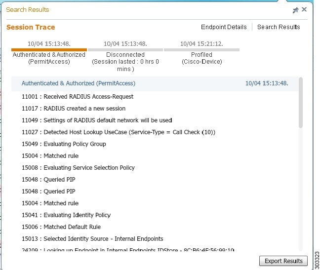
You can use the clickable timeline at the top to see major authorization transitions. You can also export the results in .csv format by clicking the Export Results button. The report gets downloaded to your browser.
You can click on the Endpoint Details link to see more authentication, accounting, and profiler information for a particular endpoint. The following figure shows an example of endpoint details information displayed for an endpoint.
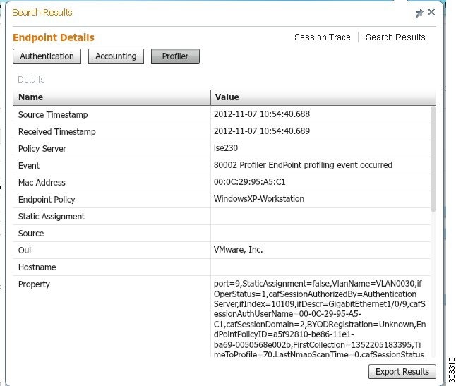
Session Removal from the Directory
Sessions are cleaned from the session directory on the Monitoring and Troubleshooting node as follows:
-
Terminated sessions are cleaned 15 minutes after termination.
-
If there is authentication but no accounting, then such sessions are cleared after one hour.
-
All inactive sessions are cleared after five days.
Global Search for Endpoints
You can use the global search box available at the top of the Cisco ISE home page to search for endpoints. You can use any of the following criteria to search for an endpoint:
-
User name
-
MAC Address
-
IP Address
-
Authorization Profile
-
Endpoint Profile
-
Failure Reason
-
Identity Group
-
Identity Store
-
Network Device name
-
Network Device Type
-
Operating System
-
Posture Status
-
Location
-
Security Group
-
User Type
You should enter at least three characters for any of the search criteria in the Search field to display data.
Note |
If an endpoint has been authenticated by Cisco ISE, or its accounting update has been received, it can be found through the global search. Endpoints that have been manually added and are not authenticated by or accounted for in Cisco ISE will not show up in the search results. |
The search result provides a detailed and at-a-glance information about the current status of the endpoint, which you can use for troubleshooting. Search results display only the top 25 entries. It is recommended to use filters to narrow down the results.
The following figure shows an example of the search result.
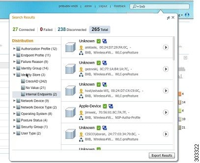
You can use any of the properties in the left panel to filter the results. You can also click on any endpoint to see more detailed information about the endpoint, such as:
-
Session trace
-
Authentication details
-
Accounting details
-
Posture details
-
Profiler details
-
Client Provisioning details
-
Guest accounting and activity
 Feedback