UP Session Activation and Deactivation Service Request Procedures

Feature Summary and Revision History

Summary Data

Table 1. Summary Data
Applicable Product(s) or Functional Area SMF
Applicable Platform(s) SMI
Feature Default Setting Not Applicable
Related Changes in this Release Not Applicable
Related Documentation Not Applicable

Revision History

Table 2. Revision History
Revision Details Release

IPv6 address support introduced to UPF tunnel end point address.

2022.04.0

Introduced support for the selection of UPF nodes based on the query parameters, such as DNN, location, and PDU session type.

2020.03.0

First introduced.

Pre-2020.02.0

Feature Description

Connection Management (CM) includes the functions to establish and release a NAS signaling connection between a UE and the Access and Mobility Management Function (AMF) over the N1 interface. This signaling connection enables the NAS signaling exchange between the UE and the core network.

The 5GS CM states determine the NAS signaling connection of the UE with the AMF. The following are the CM states:

  • CM-Idle—When a UE is in the CM-Idle state, the UE has no NAS signaling connection established with the AMF over the N1 interface. The AN signaling connection, N2 connection, and N3 connection do not exist in this state.

  • CM-Connected—When a UE is in the CM-Connected state, the UE has a NAS signaling connection with the AMF over the N1 interface. A NAS signaling connection uses an RRC Connection between the UE and the NG-RAN and an NGAP UE association between the AN and the AMF for the 3GPP access.

The CM states for the 3GPP access and the non-3GPP access are independent of each other. It implies that both the access can be in the CM-Idle state and the CM-Connected state simultaneously.

The SMF supports the UE idle-to-active and active-to-idle transition procedures.

UE-initiated Service Request Procedure

The UE in CM-IDLE state initiates the Service Request procedure to send uplink signaling messages, user data, or as a response to a network paging request. After receiving the Service Request message, the AMF performs authentication. After the establishment of the signaling connection to an AMF, the UE or network sends signaling messages, for example, PDU session establishment from UE to the SMF, through the AMF.

The Service Request procedure is used by a UE in CM-CONNECTED to request activatation of a User Plane connection for PDU sessions and to respond to a NAS Notification message from the AMF. When a User Plane connection for a PDU session is activated, the AS layer in the UE indicates it to the NAS layer.

Feature Description

The SMF supports activation and deactivation of the user plane connection of a PDU session.

The Activation or Deactivation Service Request procedure is used by a UE in CM-IDLE state or the 5GC to request the establishment of a secure connection to an AMF. The Service Request procedure is also used both when the UE is in CM-IDLE and in CM-CONNECTED to activate a User Plane connection for an established PDU session.


Note


The UE will not initiate a Service Request procedure if there is an ongoing Service Request procedure.


How it Works

This section describes how this feature works.

Deactivation of the User Plane Connection of a PDU Session

The deactivation procedure releases the logical NG-AP signaling connection and the associated N3 user plane connections, and (R)AN RRC signaling and resources.

The following reasons can trigger the initiation of AN release:

  • (R)AN-initiated with cause

    For example, O&M intervention, unspecified failure, (R)AN (for example, Radio) link failure, user inactivity, inter-system redirection, request for establishment of QoS flow for IMS voice, release due to UE-generated signaling connection release, mobility restriction, and so on.

  • AMF-initiated with cause

    For example, unspecified failure.

Limitations

The User Plane Deactivation functionality has the following limitations:

  • SMF supports only UE-initiated deactivation.

  • Location update is not supported.

Call Flow

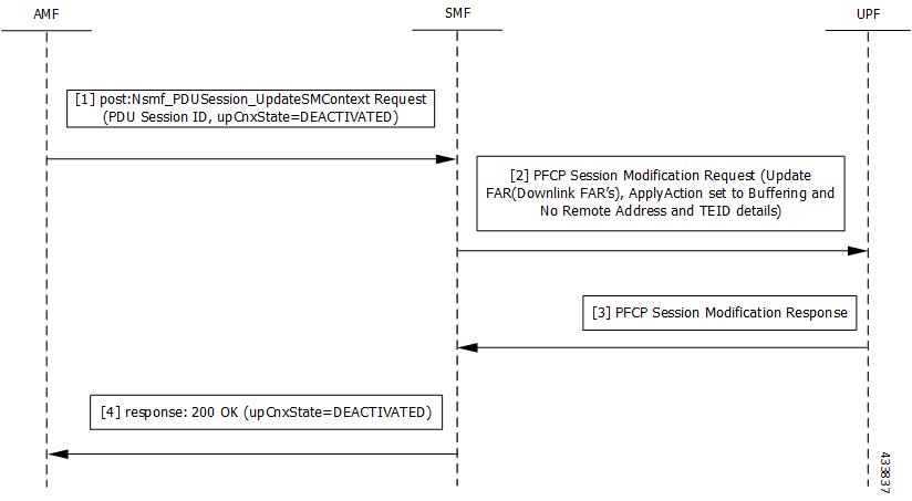
This section describes the call flow for the User Plane Deactivation of a PDU session.

The following figure illustrates the User Plane Deactivation call flow.

Figure 1. Deactivation of the User Plane Connection Call Flow
Table 3. Deactivation of the User Plane Connection Call Flow Description

Step

Description

1

NF Service Consumer requests the SMF to deactivate the user plane connection of the PDU session by sending a POST request with the following information:

  • upCnxState attribute set to DEACTIVATED.

  • User location and user location timestamp.

  • Cause of the user plane deactivation. The cause may indicate a cause received from the 5G-AN or due to an AMF internal event.

  • Other information (if required).

2

SMF deactivates and releases the N3 tunnel of the PDU session after receiving such a request. SMF initiates the PFCP Session Modification procedure towards UPF with downlink FAR updated with the following options:

  • Buffering Action is enabled without remote node "forwarding parameters" details, such as IP address and GTP-U F-TEID.

Note


NOCP (Notify the CP function) is not enabled. Support for notification is not supported on SMF.

3

SMF sets the upCnxState attribute to DEACTIVATED for the PDU session after receiving successful response from the UPF node.

4

SMF initiates a 200 OK response towards AMF including the upCnxState attribute set to DEACTIVATED.

Activation of the User Plane Connection of a PDU Session

The Service Request procedure is used when the UE is in CM-IDLE and CM CONNECTED states to activate a user plane connection for an established PDU session. The UE in CM IDLE state initiates the Service Request procedure to send uplink signaling messages, user data, or a response to a network paging request.

Call Flow

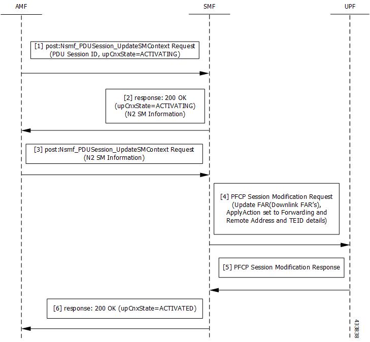
This section describes the call flow for the user plane activation of a PDU session.

The following figure illustrates the UE-initiated user plane activation call flow.

Figure 2. User Plane Connection Activation Call Flow
Table 4. UE-initiated Idle to Active Transition Call Flow Description
Step Description
1

The AMF requests SMF to activate the user plane connection of the PDU session by sending a POST request with the following information:

  • upCnxState attribute set to ACTIVATING.

  • User location, user location timestamp, and access type associated to the PDU session (if modified)

  • Other information (if necessary)

2

Upon receipt of the request, the SMF starts activating the N3 tunnel of the PDU session. The SMF returns a 200 OK response with the following information:

  • upCnxState attribute set to ACTIVATING

  • N2 SM information with the following information to request the 5G-AN to assign resources to the PDU session.

    • Transport layer address (IPv4 or IPv6 address of the UPF)

    • Tunnel endpoint of the uplink termination point for the UP data of current PDU session (that is, GTP-U F-TEID of UPF for uplink traffic)

3

Then, the AMF requests the SMF by sending POST request with the N2 SM information. If the 5G-AN succeeded in establishing resources for the PDU sessions, the N2 SM information includes the following information:

  • Transport layer address

  • Tunnel endpoint of the downlink termination point for the user data of the current PDU session. That is, GTP-U F-TEID of 5G-AN for downlink traffic.

4

The SMF initiates PFCP Session Modification procedure towards UPF with downlink FAR updated with the following options:

  • Forwarding Action enabled along with remote node forwarding parameter details, such as the IPv4 or IPv6 address of RAN and GTP-U F-TEID.

5 Upon receipt of successful response from UPF node, the SMF sets the upCnxState attribute to ACTIVATED for the PDU session.
6 The SMF initiates 200 OK response including the upCnxState attribute set to ACTIVATED towards AMF.

Network-initiated Service Request Procedure

The network-initiated service request procedure is used when the peer network needs to communicate (for example, User Plane connection activation for PDU sessions to deliver mobile terminating user data) with a UE. If the UE is in CM-IDLE state or CM-CONNECTED state in 3GPP access, the network initiates a Network Triggered Service Request procedure. If the UE is in CM-IDLE state, and asynchronous type communication is not activated, the network sends a Paging Request to (R)AN or UE. The Paging Request triggers the UE Triggered Service Request procedure in the UE. If asynchronous type communication is activated, the network stores the received message and forwards the message to the (R)AN and/or the UE (that is, it synchronizes the context with the (R)AN and/or the UE) when the UE enters CM-CONNECTED state.

Feature Description

The SMF sets up N3 tunnel to forward downlink packet to the UE for a PDU session when the UE is in the CM-Idle state.

The N3 tunnel profile helps in defining the Forwarding Action Rules (FAR) while moving from active to idle transition state.

The N3 tunnel profile configuration includes:

  • Enabling control plane notification (notify)

  • Enabling packet buffering on UPF (buffer UPF)

How it Works

When connected to the 5G core, a UE can be in CM-Connected with RRC Inactive state too. This state is between the CM-Idle and CM-Connected states.

The SMF cannot identify the UE CM state when the state is between UE and AMF. The SMF only identifies the user plane connection state. This state and the N1 and N2 transfer message response status control the behavior of SMF for network-initiated messages. These messages are for signaling modification or downlink data-related user plane activation procedures.

The following call flows describe the details for these procedures.

Call Flows

This section describes the following call flows:

Network-initiated Idle to Active Transition Call Flow

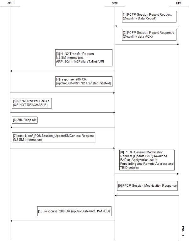
The following figure depicts the network-initiated idle to active transition call flow.

Figure 3. Network-initiated Idle to Active Transition Call Flow
Table 5. Network-initiated Idle to Active Transition Call Flow Description
Step Description
1

The UPF sends PFCP Session Report request to the SMF.

  • Report Type as DLDR (Downlink Data Report)

  • The Downlink Data Report IE contains corresponding PDR ID.

2 The SMF sends the PFCP Session Report response.
3

The SMF sends N1N2MessageTransfer to AMF with the following attributes:

  • SUPI, PDU Session ID

  • N2SMInformation as "ngapIeType":77 (id-PDUSessionResourceSetupListSUReq), "ngapMessageType":27 (id-PDUSessionResourceSetup)

  • PDUSessionResourceSetupListSUReq includes the following information:

    • PDU session id

    • QFI

    • QoS profile

    • GTP-U F-TEID of UPF for uplink traffic

    • QFI

    • QoS profile

    • S-NSSAI

    • User Plane Security Enforcement

    • UE Integrity Protection Maximum Data Rate

    • Cause

  • Area of validity for N2 SM information

  • ARP

  • Paging Policy Indication

  • 5QI

  • N1N2TransferFailure Notification Target Address (n1n2FailureTxfNotifURI)

4

The SMF receives N1N2 Transfer Response with the following status codes:

  • 200/202 OK and cause as "N1_N2_TRANSFER_INITIATED" (proceed to Step 6)

  • 409/504 and cause “UE_IN_NON_ALLOWED_AREA” (proceed to Step 7)

5 The AMF sends the N1N2 Transfer failure response. If the UE is not reachable, proceed to Step 7.
6

Then, the AMF requests the SMF by sending POST request with the following information:

  • N2 SM information received from the 5G-AN includes the following information if the 5G-AN succeeded in establishing resources for the PDU sessions.

    • Transport layer address (IPv4 or IPv6 address of UPF)

    • Tunnel endpoint of the downlink termination point for the user data for the current PDU session (that is, GTP-U F-TEID of 5G-AN for downlink traffic)

7

The SMF initiates PFCP Session Modification procedure towards UPF with downlink FAR updated with the following options:

  • If N2 Transfer is successful, Forwarding Action is enabled along with remote node forwarding parameter details, such as the IPv4 or IPv6 address of RAN and GTP-U F-TEID.

  • If the cause of transfer failure is ATTEMPTING_TO_REACH_UE or UE_IN_NON_ALLOWED_AREA:

    • Update FAR > Apply Action > NOCP: 1

    • Update FAR > Apply Action > DROP: 1

    • PFCPSMReq-Flags > DROBU: 1

  • If the cause of transfer failure is UE_NOT_REACHABLE:

    • Update FAR > Apply Action > NOCP: 0

    • Update FAR > Apply Action > DROP: 1

    • PFCPSMReq-Flags > DROBU: 1

8 Upon receipt of successful response from UPF node, the SMF sets the upCnxState attribute to ACTIVATED for the PDU session.
9 The SMF then initiates 200 OK response including the upCnxState attribute set to ACTIVATED towards AMF (only if Step 6 is completed and response is received from Step 8).
Network-initiated Service Request Rejection Call Flow

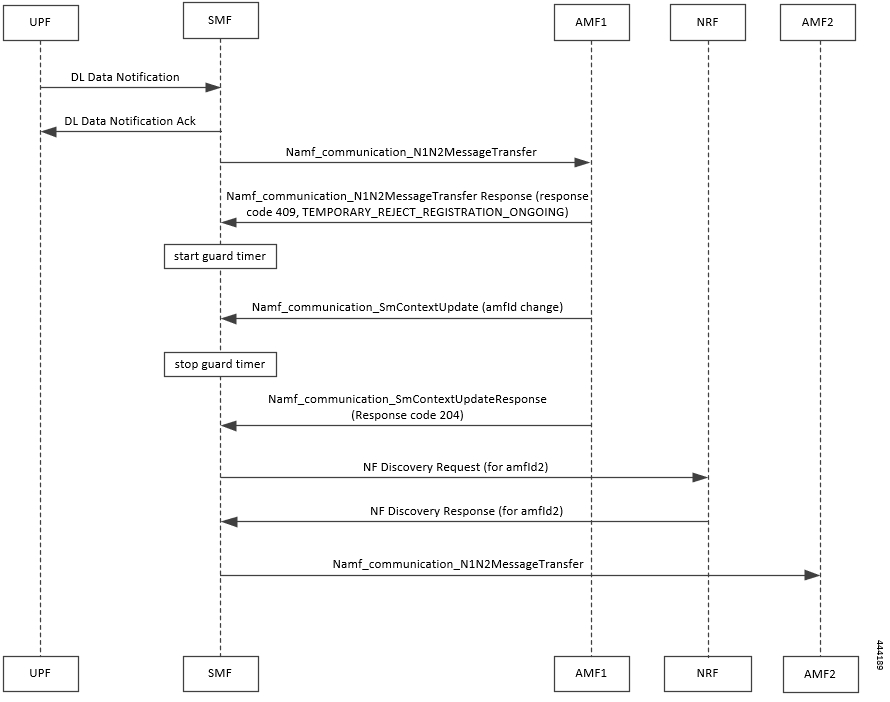
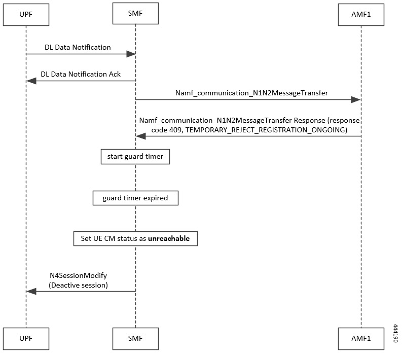
During network-initiated service request, SMF handles the temporary reject for N1N2 response message from AMF as mentioned in 3GPP TS 23.502, section 4.2.3.3.

Figure 4. Temporary Rejection Call Flow for Network-triggered Service Request - 1
Table 6. Temporary Rejection Call Flow Description for Network-triggered Service Request - 1

Step

Description

1

On receiving a trigger for service request in UP IDLE session state, SMF initiates a N1N2 message towards the AMF as part of idle mode exit procedure.

2

If UE registration procedure with new AMF is in progress, then AMF responds with temporary reject for N1N2 message with response code 409 and cause as TEMPORARY_REJECT_REGISTRATION_ONGOING or TEMPORARY_REJECT_HANDOVER_ONGOING SMF.

3

On receiving the response, SMF starts a locally configured guard timer of 2 seconds.

4

While the guard timer is running, SMF expects either a SM Context Update with AMF ID change or SM Context Update for handover.

5

On receiving SM Context Update with AMF ID change, SMF:

  1. Stops the guard timer.

  2. Removes the reference to the discovery information for old AMF.

  3. Stores the new UE location information, PLMN information, and AMF information.

  4. Sends SM Context Update response success without content.

  5. Reinitiates N1N2 message transfer to the new AMF. This involves NF discovery and subsequent transmission to the new AMF.

6

On receiving SM Context Update for N2 handover, SMF:

  1. Starts the handover procedure.

  2. Suspends the idle mode exit procedure and stops the guard timer.

  3. Removes old AMF details and stores new AMF information as part of the handover procedure completion.

  4. Resumes idle mode exit procedure after handover procedure is complete.

  5. Reinitiates N1N2 message transfer, if required, to the new AMF. This involves NF discovery and subsequent transmission to the new AMF.

Figure 5. Temporary Rejection Call Flow for Network-triggered Service Request - 2
Table 7. Temporary Rejection Call Flow Description for Network-triggered Service Request - 2

Step

Description

1

On receiving a trigger for service request in UP IDLE session state, SMF initiates a N1N2 message towards the AMF as part of idle mode exit procedure.

2

If UE registration procedure with new AMF is in progress, then AMF responds with temporary reject for N1N2 message with response code 409 and cause as TEMPORARY_REJECT_REGISTRATION_ONGOING or TEMPORARY_REJECT_HANDOVER_ONGOING SMF.

3

On receiving the response, SMF starts a locally configured guard timer of 2 seconds.

4

Once the guard timer expires, SMF:

  1. Sets the UE CM status as NotReachable.

  2. Deactivates the UP session state.

Downlink Data Notification User Plane Activation Call Flow for UE in CM-Connected State

This section describes the user plane activation procedure for notification of downlink data when the UE is in the CM-Connected state.

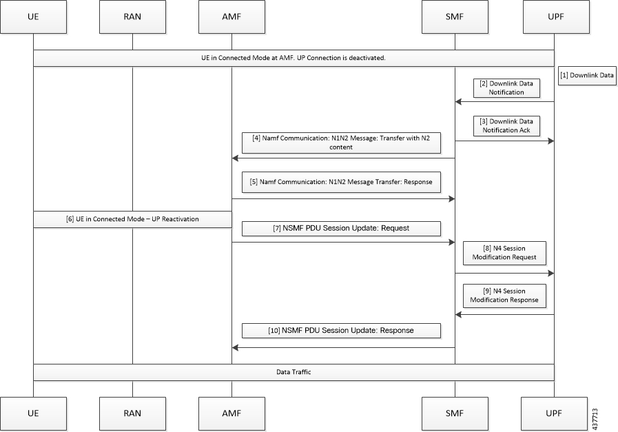
The following figure depicts the downlink data notification user plane activation call flow when the UE is in CM-Connected state.

Figure 6. Downlink Data Notification User Plane Activation Call Flow for UE in CM-Connected State
Table 8. Downlink Data Notification User Plane Activation Call Flow Description for UE in CM-Connected State
Step Description
1 When the UPF receives the downlink data for a PDU session and if no AN tunnel information is saved in the UPF for the PDU session, the UPF buffers the downlink data. The buffering is done based on the instruction from the SMF.
2 The UPF sends data notification towards SMF. This notification includes the N4 session ID, the information to identify the QoS flow for the DL data packet, and the DSCP details.
3 The SMF sends the acknowledgment data notification to the UPF.
4

The SMF initiates the NAMF communication N1 and N2 message transfer towards the AMF.

This message transfer includes the following details:

  • PDU session ID

  • N2 SM information (QFIs, QoS profiles)

  • CN N3 tunnel information

  • S-NSSAI

  • ARP

  • Paging Policy Indicator

  • 5QI

  • N1 and N2 transfer failure notification target address

  • PDU session resource setup request IE

5 As the UE is in CM-Connected state, the AMF initiates N1 and N2 transfer response. This response includes the “200 OK” status code and the “N1_N2_TRANSFER_INITIATED” cause.
6 The User Plane Reactivation procedures begin. The reactivation procedures set up the radio resources and activate the user plane to establish the N3 tunnel.
7 The AMF sends the NSMF PDU Session Update SM Context Request toward SMF. This request contains the SM information of the N2 interface. The connection state of user plane is Activated.
8 The SMF sends the N4 modification procedure toward the UPF to activate the session and to update the AN tunnel information, which is the IP and TEID. The session is activated by performing the remove buffer action and the set forward action.
9 The UPF modifies the session and sends the acknowledgment of the modification to the SMF.
10 The SMF responds to the AMF with “200 OK” status code for NSMF PDU Session Update SM Context Request with the connection state of user plane as Activated.

NOTES:

The following N1 and N2 response error cases are handled:

  • For 404 Context Not Found status, a PDU session is released.

  • For 504 or 403 status with the "UE_IN_NON_ALLOWED_AREA" and "NOT_REACHABLE" cause, an N4 modification request is sent to drop the buffered packets and exclude the CP notification for the downlink data.

  • For the N1and N2 transfer notification failure, the N4 modification request is sent to drop the buffered packets and exclude the CP notification for downlink data.

  • For 409 status code with the Retry After timer value, the N1 and N2 transfer is re-initiated after the timeout value.

  • For the 409 status code with "HIGHER_PRIORITY_REQUEST_ONGOING" cause, the lower priority N1 and N2 transfers are not allowed. Only the higher priority transfers are communicated to the AMF.

Downlink Data Notification User Plane Activation Call Flow for UE in CM-Idle State

This section describes the user plane activation procedure for notification of downlink data when the UE is in the CM-Idle state.

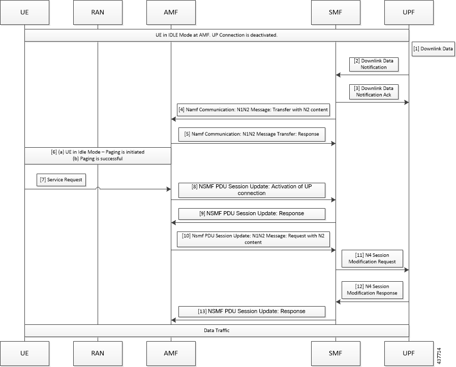
The following figure depicts the downlink data notification user plane activation call flow when the UE is in CM-Idle state.

Figure 7. Downlink Data Notification User Plane Activation Call Flow for UE in CM-Idle State
Table 9. Downlink Data Notification User Plane Activation Call Flow Description for UE in CM-Idle State
Step Description
1 When the UPF receives the downlink data for a PDU session and if no AN tunnel information is saved in the UPF for the PDU session, then based on the instruction from the SMF, the UPF buffers the downlink data.
2 The UPF sends data notification towards the SMF. This notification includes the N4 Session ID, the information to identify the QoS flow for the DL data packet, and the DSCP details.
3 The SMF sends the acknowledgment data notification to the UPF.
4

The SMF initiates the NAMF communication N1 and N2 message transfer toward AMF. This message transfer includes the following details:

  • PDU session ID

  • N2 SM information (QFIs, QoS profiles)

  • CN N3 tunnel information

  • S-NSSAI

  • ARP

  • Paging Policy Indicator

  • 5QI

  • N1 and N2 transfer failure notification target address

5 As the UE is in CM-Connected state, the AMF initiates N1 and N2 transfer response. This response includes the “202 Accepted” status code and “ATTEMPTING_TO_REACH_UE” cause.
6 The AMF triggers the paging procedure towards the UE.
7 The UE receives the paging request and initiates the requested service to activate the session.
8 The AMF initiates the NSMF PDU Session Update SM Context Request towards SMF with connection state of user plane configured as Activating.
9

The SMF responds to the AMF with “200 OK” status code for the NSMF PDU Session Update SM Context Request. This request includes the following details:

  • N2 SM information (QFIs, QoS profiles)

  • CN N3 tunnel information

  • S-NSSAI

  • ARP

  • Paging Policy Indicator

  • 5QI

  • N1 and N2 transfer failure notification target address

  • PDU session resource setup request IE

10 The AMF sends the NSMF PDU Session Update SM Context Request towards the SMF. This request contains the SM information of the N2 interface. The connection state of user plane is Activating.
11 The SMF initiates the N4 Modification procedure towards the UPF to activate the session and to update the AN tunnel information, which is the IP and TEID. The session is activated by performing the remove buffer action and set forward action.
12 The UPF modifies the session and sends the acknowledgment of the modification to the SMF.
13 The SMF responds to the AMF with “200 OK” status code for NSMF PDU Session Update SM Context Request with connection state of user plane as Activated.

Standards Compliance

The Network-initiated Service Request feature complies with the 3GPP TS 23.502, V15.6.0 (2019-10).

Limitations

SMF does not support location update and access-type changes.

Configuring N3 Tunnel Profile

Use the N3 tunnel profile for buffering or notifying actions towards SMF when the UPF receives the downlink data and the N3 tunnel is unavailable. To configure the N3 tunnel profile, use the following sample configuration:

config 
   profile n3-tunnel n3_profile_name 
      buffer upf 
      notify 
      end 

NOTES:

  • profile n3-tunnel n3_profile_name : Specify the N3 tunnel profile name. n3_profile_name must be a string.

  • buffer upf : Configure buffering for Downlink Data.

  • notify : Enable downlink data notification from UPF.

Always-On PDU Session Support

Feature Description

The always-on Protocol Data Unit (PDU) session means that the user plane is always active. Applications such as the IP Multimedia Subsystem (IMS) requires an always-on PDU session.

The UE requests the establishment of a PDU session as an always-on PDU session based on the request indication of the upper layers. It is the network that decides whether to establish a PDU session as an always-on PDU session.

How it Works

Call Flows

This section describes the call flows for Always-On PDU Session support.

PDU Session Establishment Call Flow

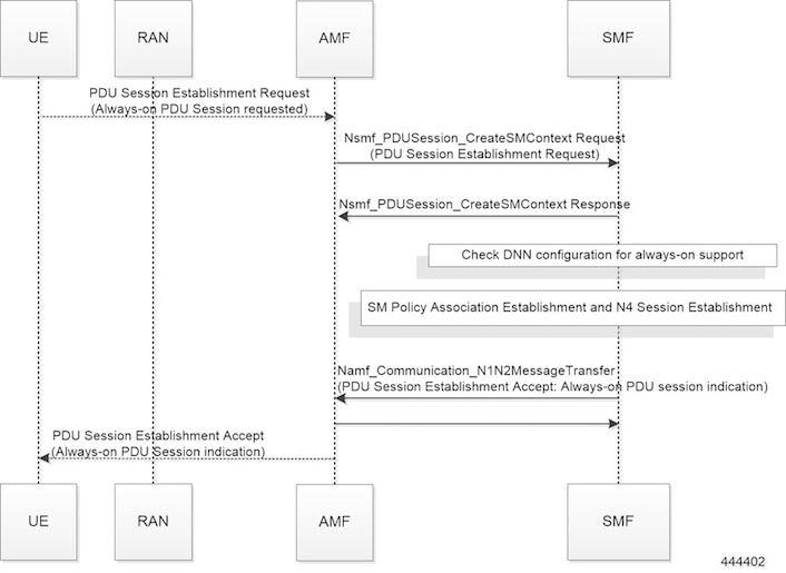
This section describes the PDU session establishment procedure involving a request for Always-on PDU session initiation in the Create Session Request.

The following figure illustrates the PDU Session Establishment call flow.

Figure 8. PDU Session Establishment Call Flow


Table 10. PDU Session Establishment Call Flow Description
Step Description
1

If the UE requests to establish an always-on PDU session, the UE includes an "Always-on PDU Session Requested" IE in the PDU Session Establishment Request message.

2

The SMF checks the DNN profile to determine whether the always-on support is enabled.

3

The SMF includes an "Always-on PDU Session Indication" IE in the PDU Session Establishment Accept message if one of the following is true:

  • "Always-on PDU Session Indication" is sent with value as "enabled" if the always-on configuration is enabled under the DNN profile.

  • "Always-on PDU Session Indication" is sent with value as "disabled" when the "Always-on PDU Session Request" IE is received and configuration is disabled.

4

The SMF does not include an "Always-on PDU Session Indication" only when both these conditions are true:

  • If the UE did not send an "Always-on PDU Session Requested" IE.

  • If the always-on configuration is disabled in the DNN profile.

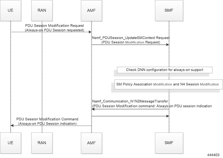
UE-requested PDU Session Modification Call Flow

This section describes the UE-requested PDU session modification procedure in which the Always-on PDU session indication is sent.

The following figure illustrates the UE-requested PDU Session Modification call flow.

Figure 9. UE-requested PDU Session Modification Call Flow


Table 11. UE-requested PDU Session Modification Call Flow Description
Step Description
1

The UE sends an "Always-on PDU Session Requested" IE in the PDU Session Modification Request message.

2

The SMF checks the DNN profile to determine whether the always-on support is enabled.

3

The SMF includes "Always-on PDU Session Indication" in the PDU Session Modification Command when one of the following is true:

  • "Always-on PDU Session Indication" is sent with the value as "enabled" when the always-on configuration is enabled under the DNN profile.

  • "Always-on PDU Session Indication" is sent with the value as "disabled" when the "Always-on PDU Session Request" IE is received and configuration is disabled.

4

The SMF does not include the "Always-on PDU Session Indication" only when both these conditions are true:

  • If the UE did not send the "Always-on PDU Session Requested" IE.

  • If the always-on configuration is disabled in the DNN profile.

Note


As per 3GPP TS 23502, for a PDU session that was established in the EPS, when the UE moves from EPS to 5GS for the first time, the UE includes an "Always-on PDU Session Requested" indication in the PDU Session Modification Request message if it wants to change the PDU session to an "always-on" PDU session.

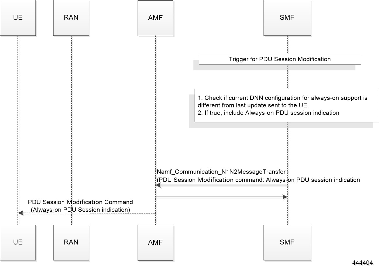
Network-requested PDU Session Modification Call Flow

This section describes the network-requested PDU session modification procedure in which the Always-on PDU session indication is sent.

The following figure illustrates the network-requested PDU Session Modification call flow.

Figure 10. Network-requested PDU Session Modification Call Flow


Table 12. Network-requested PDU Session Modification Call Flow Description
Step Description
1

The SMF decides to trigger a PDU Session Modification due to PCF, UDM, or RAN initiated procedures.

2

The SMF checks the DNN profile to determine whether the always-on support is enabled.

3

The SMF determines whether the current DNN configuration for always-on is different from the last indication sent to UE. If it differs, the SMF includes the "Always-on PDU Session Indication" IE in the PDU Session Modification Command message.

Configuring Always-On PDU Session Support

To configure the parameter for always-on PDU session support, use the following sample configuration:

config 
   profile dnn dnnprofile_name 
      always-on { false | true } 
      end 

NOTES:

  • always-on { false | true } : Configure the always-on PDU session support.

    • false : Disable always-on PDU session support.

    • true : Enable always-on PDU session support.

  • The value of "Always-on PDU Session Indication" IE sent in the PDU Session Establishment Accept message is based on the always-on configuration in DNN profile. That is, if the always-on configuration is enabled under the DNN profile, then the "Always-on PDU Session Indication" IE is sent with value as "enabled".

Verifying Always-On PDU Session Support

To verify the always-on PDU session support., use the show subscriber supi supi_id nf-service smf CLI command.

The show output for always-on PDU session support displays one of the following options:

  • “alwaysOn”: “UE Requested”

  • “alwaysOn”: “Enabled”

  • “alwaysOn”: “UE Requested & Enabled”

The following is a sample output of the command:

show subscriber supi imsi-123456789012345 nf-service smf
subscriber-details
{
  "status": true,
  "genericInfo": {
    "supi": "imsi-123456789012345",
    "pei": "imei-123456786666660",
    "pduSessionId": 5,
    "pduSesstype": "Ipv4PduSession",
   "accessType": "ACCESS_5G",
    "dnn": "intershat",
    "plmnId": {
      "mcc": "123",
      "mnc": "456"
    },
    "sScMode": 1,
    "uetimeZone": "UTC+12:00",
    "allocatedIp": "209.165.201.4",
    "nrLocation": {
      "ncgi": {
        "mcc": "123",
        "mnc": "456",
        "nrCellId": "123456789"
      },
      "tai": {
        "mcc": "123",
        "mnc": "456",
        "tac": "1820"
      }
    }
    “alwaysOn”:  “UE Requested”
  },
  "accessSubData": {
    "amfID": "AFbe08",
    "amfPlmnId": {
      "mcc": "123",
      "mnc": "456"
    },
    "ueCmStatus": "UeCMConnected",
    "amfNrfID": "76517361-338e-4d77-bc76-713a79779574"
  },
  "policySubData": {
    "TotalDynamicRules": 1,
    "TotalFlowCount": 1,
    "TotalNonGBRFlows": 1,
    "pccRuleList": [
      {
        "pccRuleId": "defaultrule",
        "qfi": 1,
        "mbrDl": 125000000,
        "mbrUl": 100000000,
        "flowInformation": [
          {
            "flowDirection": 3,
            "flowDescription": "permit out ip from any to any"
          }
        ]
      }
    ],
    "qosFlow": [
      {
        "qfi": 1,
        "GBRFlow": "False",
        "bindingParameters": {
          "x5Qi": 5,
          "arp": {
            "preemptCap": 1,
            "preemptVuln": 1,
            "priorityLevel": 15
          },
          "priorityLevel": 1
        },
        "AggregatedULMFbr": 100000000,
        "AggregatedDLMFbr": 125000000,
        "pccRuleList": "defaultrule"
      }
    ]
  },
  "chargingData": {},
  "upfServData": {
    "numberOfTunnels": 1,
    "smfSeid": 21790984727,
    "UPState": "Activated",
    "mapping": {
      "tunnelMapping": [
        {
          "TunnelID": 1,
          "tunnelName": "gnbTunnel"
        }
      ]
    }
  }
}
 

Always-On PDU Session OAM Support

This section describes operations, administration, and maintenance information for this feature.

Bulk Statistics Support

The Always-On PDU Session feature supports the following bulk statistics.

Table 13. Always-On PDU Session Bulk Statistics

Bulk Statistics

Description

always-on-pdu

Tracks the number of always-on PDU sessions.

Always-on-pdu-requested

Requests the always-on PDU session.

always-on-pdu-accepted

Accepts the always-on PDU session request.

Always-on-pdu-rejected

Rejects the always-on PDU session request.

pdusetup_req_alwayson_requested

The number of Session Establishment Request messages received with "Always-On PDU Session Requested".

pdusetup_acc_alwayson_allowed

The number of Session Establishment Accept messages sent with "Always-On PDU Session Indication" enabled.

pdusetup_acc_alwayson_not_allowed

The number of Session Establishment Accept messages sent with "Always-On PDU Session Indication" disabled.

pdumod_req_alwayson_requested

The number of Session Modification Request messages received with "Always-On PDU Session Requested".

pdumod_cmd_alwayson_allowed

The number of Session Modification Command messages sent with "Always-On PDU Session Indication" enabled.

pdumod_cmd_alwayson_not_allowed

The number of Session Modification Command messages sent with "Always-On PDU Session Indication" disabled.

pdumod_cmd_nw_init_alwayson_allowed

The number of network-initiated Session Modification Command messages sent with "Always-On PDU Session Indication" enabled.

smf_session_counters

The gauge to show the number of active always-on PDU sessions.

DLDR Handling for N3 Connection Reactivation

Feature Description

When the SMF doesn't trigger the N1N2 setup request on the N11 interface when UPF received the Downlink Data Request (DLDR), the difference in the upContext state between SMF and UPF resulted in UPF triggering the DLDR. With the N3 in an inactive state, UPF used to send the session report request to SMF. With this feature, the SMF reactivates N3 when DLDR is received in N3 activated state.

How it Works

The reactivate-n3-on-dupl-activation-dldr CLI command is added in the supported features at SMF to reactivate the N3 when DLDR is received in the N3 activated state. After this CLI is enabled and if the DLDR is received in the ACTIVATED state, then SMF changes the upState to DEACTIVATED and reactivates the N3 connection.

Configuring N3 Connection Reactivation

To configure N3 connection reactivation, use the following sample configuration.


config 
   profile smf profile_name instances instance-id supported-features [ reactivate-n3-on-dupl-activation-dldr ] 
       [ vsmf dtssa acscr] 

NOTES:

  • supported-features [ reactivate-n3-on-dupl-activation-dldr ] : Reactivate N3 when the DLDR received is in the N3 activated state in supported-features.