AN-initiated Session Modification and Release

Feature Summary and Revision History

Summary Data

Table 1. Summary Data

Applicable Product(s) or FunctionalArea

SMF

Applicable Platform(s)

SMI

Feature Default Setting

Enabled – Always-on

Related Changes in this Release

Not Applicable

Related Documentation

Not Applicable

Revision History

Table 2. Revision History

Revision Details

Release

First introduced.

2020.02.0

Feature Description

The NG-AP signaling connection can be lost due to RAN or AMF failure. In this scenario, the RAN or AMF initiates the AN release procedure without relying on the signaling between RAN and AMF.

The AN-initiated PDU session release procedure involves releasing the logical NG-AP signaling connection for the UE between the RAN and the AMF and the associated N3 User Plane connections, and RAN signaling connection between the UE and the RAN and the associated RAN resources.

The initiation of AN release may be due to:

  • RAN-initiated with cause, for example, O&M Intervention, Unspecified Failure, RAN (for example, Radio) Link Failure, User Inactivity, Inter-System Redirection, request for establishment of QoS Flow for IMS voice, Release due to UE-generated signaling connection release, mobility restriction, Release Assistance Information (RAI) from the UE, and so on, or

  • AMF-initiated with cause like Unspecified Failure, and so on


Note


For AN-initiated modification, SMF does not send policy update message towards PCF as mentioned in step 2 of section 4.3.3.2-1: UE or network requested PDU Session Modification in 3GPP TS 23.502.


How it Works

This section describes how the NG-AP signaling connection, UP connections, and AN resources associated with the PDU session are released.

RAN-initiated PDU Session Release Call Flow

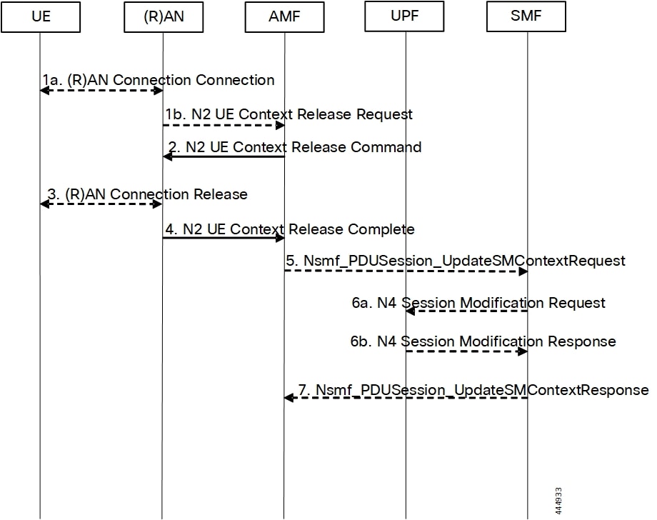
The following call flow diagram represents the messages that are exchanged between UE and SMF when PDU session release is initiated by RAN or AMF. The RAN session release is as defined in 3GPP 23.502.

For this procedure, the impacted SMF and UPF are all under control of the PLMN serving the UE, for example, in Home-Routed roaming case, the SMF and UPF in HPLMN are not involved.

Figure 1. RAN-initiated PDU Session Release Call Flow
Table 3. RAN-initiated PDU Session Release Call Flow Description

Step

Description

1

In cases, such as Radio Link Failure or RAN internal failure, the RAN decides to initiate the UE context release and sends an N2 UE Context Release Request message to the AMF.

If the reason for the release is the NG-RAN received an AS Release Assistance Indicator (RAI), NG-RAN does not release the RRC connection but sends an N2 UE Context Release Request message to the AMF. If the AS RAI indicates that only a single downlink transmission is expected, then NG-RAN sends only the N2 UE Context Release Request after a single downlink NAS PDU or N3 data PDU has been transferred.

If N2 Context Release Request cause indicates the release, then release is requested due to user inactivity or AS RAI. Then, the AMF continues with the AN Release procedure unless the AMF is aware of pending MT traffic or signaling.

2

Upon receiving Release Request message from RAN, AMF sends N2 UE Context Release Command to RAN.

If the AMF receives Service Request or Registration Request to establish another NAS signaling connection through RAN, after successfully authenticating the UE, the AMF releases the existing NAS signaling connection. Then, the AMF continues the Service Request or Registration Request procedure.

The Cause indicates either the cause from (R)AN or the cause due to an AMF event.

3

If the UE connection is not released in Step 1, the RAN performs one of the following operations:

  • the RAN deletes the context of UE upon receiving RAN connection release confirmation

  • the RAN locally releases the RRC connection if the Cause in the Context Release Command indicates that the UE has locally released the RRC connection

4

Note


When the UE does not acknowledge the RRC Connection Release, perform this step after Step 2.

The RAN releases the N2 signaling connection with the AMF for the UE and sends an N2 UE Context Release Complete message to the AMF. This message includes the following information:

  • list of PDU session IDs that RAN serves with active N3 user plane

  • user location information

  • age of location information

The AMF receives the UE Radio Capability information or NB-IoT specific UE Radio Access Capability Information from the NG-RAN node. The NG-RAN sends paging assistance data for CE-capable UE, if available, to AMF through the N2 UE Context Release Complete message. The AMF stores the received Paging Assistance Data for CE-capable UE in the UE context for subsequent paging procedure.

Note


If the PLMN has configured secondary RAT usage reporting, the NG-RAN node provides RAN usage data report.

5

For each of the PDU sessions in the N2 UE Context Release Complete, the AMF sends Nsmf PDU Session Update SM Context Request to SMF. This request message includes the following information:

  • PDU Session ID

  • PDU Session Deactivation

  • Cause (same as Step 2)

  • Operation Type

  • User Location Information

  • Age of Location Information

  • N2 SM Information (Secondary RAT usage data)

If the Release Request message includes list of PDU session IDs with active N3 user plane as in Step 1, SMF and AMF perform Step 5 through Step 7 before Step 2.

The Operation Type is set to "UP deactivate" to indicate deactivation of user plane resources for the PDU session.

If the PDU sessions use Control Plane CIoT 5GS Optimization and if the UE negotiates the use of extended idle mode DRX, the AMF communicates that the UE is unreachable for downlink data to the SMF.

If the PDU sessions use Control Plane CIoT 5GS Optimization and if the UE negotiates the use of MICO mode with active time, the AMF communicates that the UE is unreachable for downlink data to the SMF after the expiry of active time.

6

For PDU sessions not using Control Plane CIoT 5GS Optimization, the SMF sends an N4 Session Modification Request to the UPF. This request message includes the following details to indicate:

  • whether or not to remove the tunnel information of AN or UPF terminating N3.

  • whether or not to buffer the incoming DL PDU.

If the AMF indicates that the UE is unreachable for downlink data, the SMF initiates an N4 Session Modification procedure to activate buffering in the UPF.

If a PDU session uses multiple UPFs, the SMF sends the Modification Request to the specific UPF that terminates N3, and then releases the N4 session associated with that UPF.

If the AN Release is due to user inactivity or UE redirection, the SMF preserves the GBR QoS Flows. Otherwise, the SMF triggers the PDU Session Modification procedure for the GBR QoS Flows of the UE after the AN Release procedure is completed.

If the Ultra Reliable Low Latency Communication (URLLC) uses redundant I-UPFs, the SMF sends N4 Session Modification Request to each I-UPF. The SMF uses the buffering instructions to select the redundant I-UPFs for buffering, dropping, or forwarding the DL packets.

If the URLLC uses redundant N3 tunnels, the SMF sends the modification request to the UPF of N3 termination point to remove the dual AN Tunnel Info for N3 tunnel of the corresponding PDU session.

6b

The UPF sends N4 Session Modification Response to the SMF.

7

The SMF sends Nsmf PDU Session Update SM Context Response to the AMF. Then, the AMF enters CM-IDLE state after releasing the N2 and N3 connection and sends an acknowledgment to the SMF.

RAN-initiated QoS Flow Mobility for Dual Connectivity

The RAN-initiated QoS flow mobility procedure involves transferring QoS flows to and from Secondary RAN Node without reallocation of SMF and UPF. It is assumed that the IP connectivity exists between the UPF and the primary RAN node, and between the UPF and the secondary RAN node.

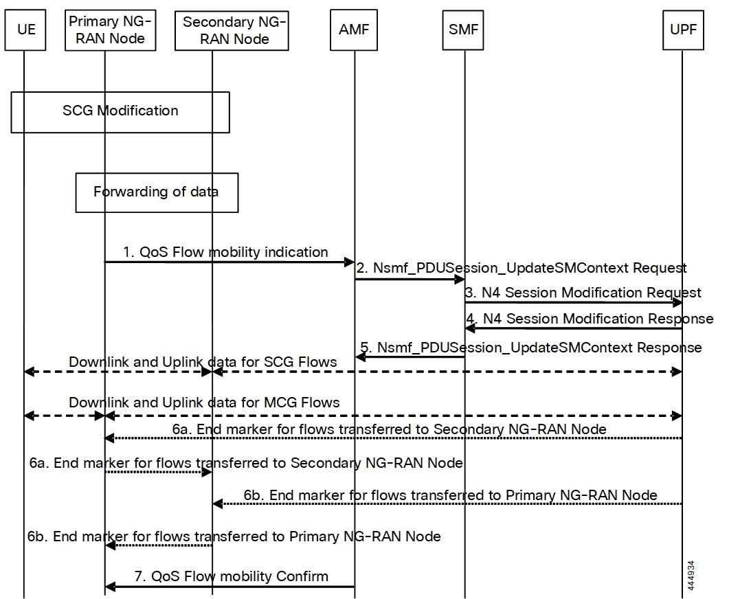
The following call flow diagram represents the QoS flow exchange between Primary and Secondary RAN Nodes.

Figure 2. NG-RAN initiated QoS Flow Mobility Procedure
Table 4. NG-RAN initiated QoS Flow Mobility Call Flow Description

Step

Description

1.

The primary RAN node sends a N2 QoS Flow mobility indication message to the AMF. The QoS flow pertains to the Master Cell Group (MCG) and Secondary Cell Group (SCG). The indication message includes PDU session ID, QFIs, and AN tunnel information. The tunnel information includes the new RAN tunnel endpoint for the QFIs.

2.

AMF sends Nsmf PDU Session Update SM Context request to SMF. This request message includes N2 QoS flow mobility indication message and PDU session ID.

3.

The SMF sends an N4 Session Modification Request message to the UPF. This Modification Request includes PDU session IDs, QFIs, and AN tunnel information for downlink user plane.

4.

The UPF switches the requested QFIs, and then sends an N4 Session Modification Response message to the SMF. The response message includes CN tunnel information for uplink traffic.

Important


Step 7 can occur anytime after receipt of N4 Session Modification Response at the SMF.

5.

SMF sends Nsmf PDU Session Update SM Context response to AMF for QFIs of the PDU session which have been switched successfully. If none of the requested QFIs are switched successfully, the SMF sends an N2 QoS flow mobility failure message.

6.

To assist the reordering function in the Primary RAN node and/or Secondary RAN node, for each affected N3 tunnel, the UPF sends one or more "end marker" packets on the old tunnel immediately after switching the tunnel for the QFI. The UPF starts sending downlink packets to the target NG-RAN.

7.

The AMF sends an acknowledgement message to the primary RAN node. This message indicates the completion of QoS flow mobility procedure.