Policy and User Plane Management

Feature Summary and Revision History

Summary Data

Table 1. Summary Data
Applicable Product(s) or Functional Area SMF
Applicable Platform(s) SMI
Feature Default Setting Disabled – Configuration Required
Related Changes in this Release Not Applicable
Related Documentation Not Applicable

Revision History

Table 2. Revision History
Revision Details Release

Introduced support for the following:

  • Co-located UPF Selection

  • Enhanced Limits for Maximum Groups in Bandwidth Policy Configuration

  • Handling Session Report Rejection Procedure

  • New Format of Outer Header information element (IE)

2021.01.0

Introduced support for the following:

  • UPF node selection based on DNN and PDU Session type

  • Modification of authorized default QoS

  • Additional session report and UPF node report request

2020.03.0

First introduced.

Pre-2020.02.0

Feature Description

The SMF is one of the control plane NFs that provide the Session Management service in the 5G core network. The SMF manages the PDU session lifecycle through the following session management procedures:

  • PDU Session Establishment

  • PDU Session Modification

  • PDU Session Release

This chapter describes the policy and user plane management features.

  • Policy Management—Policy Control Function (PCF) or the local configuration controls the policies managed on SMF. The PCF sends Policy and Charging Control (PCC) rules along with the applicable QoS and charging information to the SMF. The SMF uses this information to define QoS flows and apply QoS enforcement (via User Plane Function (UPF) and charging towards Charging Function (CHF). The PCC rules can be configured locally as well. The locally configured policy rules are labelled as static or predefined rules.

  • User Plane Management—The user plane management on SMF includes selection of UPF and maintaining per session and node level user plane data. The SMF performs Path management of the UPF nodes. At a per session level, SMF publishes the Packet Detection Rules (PDRs), QoS Enforcement Rules (QERs), Forwarding Action Rules (FARs), and Usage Reporting Rules (URRs) to the UPF. Then, the SMF enforces the policy rules received from PCF or configured locally.

QoS Management on SMF

Feature Description

The primary functionality of the SMF is to manage the flow-based QoS model. SMF interacts with the Unified Data Management (UDM) and Policy Control Function (PCF) to get the subscribed and authorized QoS parameters for GBR and non-GBR flows and passes on the relevant information to UE (NAS), gNB (NGAP), and UPF (PFCP) so that all nodes on the network provide the desired QoS to the PDU session.

Use Cases

This section describes the various use case scenarios that can lead to creation, modification, and deletion of QoS-Profile and the corresponding actions taken.

QoS-Profile associated to the PDU Context will be modified in the following scenarios:

  • Response from PCF for SMPolicyContextData

  • Update Notify from PCF

  • Update response from PCF on behalf of Update request sent initially from SMF

  • Update request from SMF will be triggered in the following cases:

    • UE triggered modify request

    • AN triggered modify request

    • UDM triggered modify request

Setup Creation
Figure 1. Setup Creation

Based on the content received in SMPolicyDecision, SMF pushes the following towards various interfaces.

  • UPF:

    • Set of PDR derived from PCC rules

    • Set of QER derived from QoS flows which in turn are derived from QosDescription/QosCharacteristics from PCF

    • One extra QER that will be shared will be derived from SessRules

  • N1:

    • Set of QoS rules derived from QosFlows

    • Each QosRule has its associated packet filter

  • N2:

    • Set of QoS Flow information

UE/AN-initiated Modify
Figure 2. UE/AN-initiated Modify
UDM/PCF-initiated Modify
Figure 3. UDM/PCF-initiated Modify
  • N1:

    • PDU Session Modification command will be triggered from SMF. It can change Session-AMBR and QoS rules.

    • PDU Session Modification Request will be triggered from UE. It can change the QoS rules and maximum number of support-ed packet filters.

      In either case, the QoS rule change can happen from the following:

      • Packet filter add/delete/replace

      • Rule Precedence of QoS Rule

      • QoS Parameter – 5QI/MBR/GBR

  • N2:

    • PDU Session Resource Modify Request will be triggered from SMF. It can change the existing QoS flow that is installed or delete the QoS flow already installed. If the Modify request is received, the parameters - ARP, GBR/MBR, Priority level, and so on, can change.

    • PDU Session Resource Notify will be triggered from AN. This happens when certain flow is to be released, not fulfilled any-more and fulfilled again.

Subscribed QoS

The UDM NF maintains the subscribed QoS for the UE in the Session Management Subscription Data. During the PDU setup procedure, the SMF posts an HTTP2 GET request (see 3GPP TS 29.503) for a resource URI "/{supi}/sm-data" to fetch the Session Management Subscription Data. The subscription data has a set of DNN configurations, one for each DNN which the subscriber is allowed to access. Each DNN configuration consists of the following parameters:

  • sessionAMBR: The maximum aggregated uplink and downlink bit rates to be shared across all non-GBR QoS flows in each PDU session.

  • 5gQosProfile: The default 5G QoS Indicator (5QI) and default ARP values are provided to the SMF in the Session Management Subscription Data in this attribute of the DNN configuration.

The SMF saves the subscribed QoS parameters and sends this across to the PCF during the SM Policy Association Establishment procedure.

QoS Negotiation

The SMF negotiates the QoS with the PCF by initiating a Policy Association Establishment procedure as defined in 3GPP TS 23.502, section 4.16.4. The sessionAMBR and 5gQosProfile parameters that are received from subscription are included in the Npcf_SMPolicyControl_Create request to PCF. The response from PCF may contain the following:

  • Session Rules: A session rule consists of policy information elements that are associated with the PDU session. The QoS related information is Authorized session AMBR and Authorized default QoS.

    • Policy Charging and Control (PCC) Rules: The PCC rule includes the FlowDescription, FlowDirection, and RefQosData parameters among other information. There could be one or more PCC rules in the response from PCF.

      • FlowDescription: This parameter contains packet filters for IP flows. For IP PDU Session Type, the Packet Filter Set supports packet filtering based on at least any combination of:

        - Source / Destination IP address or IPv6 prefix

        - Source / Destination port number

        - Protocol ID of the protocol above IP/Next header type

        - Type of Service (TOS) (IPv4) / Traffic class (IPv6) and mask

        - Flow Label (IPv6)

        - Security parameter index

      • FlowDirection: This parameter indicates the direction of data traffic on which the rule has to be applied. This could be UPLINK, DOWNLINK, or BIDIRECTIONAL.

      • RefQosData: This parameter refers to the QoS description to be applied to this PCC Rule. This matches the QosId of at least one of the QoS Description entries in the response from PCF.

    • QoS Characteristics: The QoS characteristics include parameters such as:

      • Resource Type (GBR, Delay critical GBR, or non-GBR)

      • Priority Level

      • Packet Delay Budget

      • Packet Error Rate

      • Averaging Window

      • Maximum Data Burst Volume (for the Delay-critical GBR resource type only)

        This attribute in the response from PCF is meant to be used only for non-standard 5QI values. For standard 5QI values, the characteristics are already defined in 3GPP TS 23.501, section 5.7.4.

    • QoS Description: The QoS Description parameter consists of the following:

      • 5QI: Standard or non-standard from the QoS Characteristics attribute

      • Uplink and Downlink GBR

      • Uplink and Downlink MBR

      • Maximum Packet Loss Rate

      • QosId – Referenced in PCC rules

      • Default QoS Indication

        There could be more than one QoS Description attribute in the response from PCF.

QoS Flow Management

The information, that is received from PCF in the Npcf_SMPolicyControl_Create response, is used to create and update QoS Flows in the SMF. Each QoS flow has a unique QoS Flow ID (QFI) and one or more PCC rules map to a single QoS flow.

The following figure illustrates how to manage the QoS information at the SMF.

Figure 4. QoS Information Management at SMF

Each QoS Flow in SMF is a combination of three sets of information:

  • QoS profile: A QoS profile stores all QoS attributes for a particular QoS Flow.

    • Some QoS parameters known as the QoS flow binding parameters make a unique combination for one QoS Flow of one PDU Session. This means that, for a PDU session, each unique combination of these parameters represents a separate QoS Flow. These parameters are – 5QI, ARP, Priority, Maximum Data Burst Volume, Average Window and QNC.

    • If the 5QI for the QoS profile of a QoS Flow is non-standard, some additional QoS characteristics such as Resource Type, Packet Delay Budget, Packet Error rate, and Averaging Window are also saved in the QoS profile.

    • The QoS profile also maintains multiple QoS Descriptions, each with a unique QoSId for a specific PDU session. Each QoS Description contains the uplink and downlink GBR, uplink and downlink MBR, maximum packet loss rate and default QoS indication.

  • QoS Rules: A QoS rule is a collection of packet filters that associates with a particular QoS Description in the QoS profile of the QoS flow. The packet filters directly map to the flow descriptions received in the PCC rules in the Npcf_SMPolicyControl_Create response from PCF. The QoS rules have a reference to the QoSId of the QoS Descriptions that the rules associate with.

  • PDRs: Each QoS rule maps to two Packet Detection Rules (PDR) to be sent to the UPF. One PDR is for uplink direction and the other PDR is for downlink direction. The Service Data Flow (SDF) filters in the Packet Detection Information (PDI) attribute within the PDRs map the packet filters of the QoS rule. Each PDR then maps to a Forwarding Action Rule (FAR), which determines the forwarding action for the packets matching the SDF filters. Each PDR is also associated to a QoS Enforcement Rule (QER) which carries the QoS information and it maps to the QoS description associated with the QoS rule.

QoS Communication on 3GPP Interfaces

The negotiated QoS mainly needs to be communicated to the UE (N1 interface using NAS protocol), gNB (N2 interface using NGAP protocol), and UPF (N4 interface using PFCP protocol).

  • N1 Interface: On the N1 interface, the session management messages are exchanged between UE and SMF through AMF. The NAS messages are encoded into an N1 container and sent to SMF or received from SMF.

    • All the negotiated/authorized QoS related information that needs to be sent out to the UE are found in the Authorized QoS rules and Session-AMBR attributes of the PDU SESSION ESTABLISHMENT ACCEPT message in an N1 container, during the PDU session establishment (see 3GPP TS 24.501, section 8.3.2).

    • The PDU SESSION MODIFICATION REQUEST message from UE contains the Requested QoS Rules during the UE initiated QoS modification.

    • The Authorized QoS rules and Session-AMBR attributes are also present in the PDU SESSION MODIFICATION COMMAND message sent from SMF to UE during the PCF/SMF initiated QoS modification.

    • The format of the QoS Rule NAS attribute is defined in 3GPP TS 24.501, section 9.10.4.9. This attribute mainly consists of the packet filter list, QFI, and QoS parameters on a per QoS rule basis. This information is available in the QoS rule within the QoS flow.

  • N2 Interface: On the N2 interface, SMF sends an N2 container to the gNB through AMF. The N2 container is ASN.1 encoded data and consists of specific information elements of NGAP messages. All the QoS related information to gNB is encoded and sent/received in N2 containers to/from SMF. The NGAP IEs and the corresponding NGAP messages that will finally carry the IE from AMF to gNB are listed in 3GPP TS 29.502, section 6.1.6.4.3.

    • During the PDU session setup, the SMF sends N1N2MessageTransfer to AMF with the N2 container in the PDU Session Re-source Setup Request Transfer IE. This IE contains PDU Session Aggregate Maximum Bit Rate and QoS Flow Setup Request List. The QoS Flow Setup Request List contains QoS Flow Level QoS Parameters (GBR flow information, 5QI, and so on). These are defined in 3GPP TS 38.413, section 9.3.1.

    • Similar information (QoS Flow Level QoS Parameters) is also sent by SMF in the PDU Session Resource Modify Request Transfer IE in an N2 container during the PCF/SMF initiated QoS Modification procedure.

      The information required to create the N2 container in SMF is present in the QoS profile of a QoS flow as described in the previous section.

  • N4 Interface: On the N4 interface, the SMF sends the QoS information in the form of Packet Detection Rule (PDR), Forwarding Action Rule (FAR), and QoS Enforcement Rule (QER).

    • The PDR contains the SDF filters in the PDI IE. These SDF filters are the packet filters set in the QoS Rule of a QoS flow.

    • The QER contains the QoS parameters as per the QoS Description to which the QoS rule is associated.

      The contents of PDR, FAR, and QER are defined in 3GPP TS 29.244.

QoS Modification

QoS modification may result in one of the following scenarios:

  • QoS Flow Addition: Whenever a negotiated QoS is received from PCF either as part of UE initiated modification or PCF initiated QoS modification, the SMF extracts the received QoS Flow Binding Parameters (5QI, ARP, Priority, Max Data Burst Volume, QNC). If there is no QoS Flow with the received combination of the flow binding parameters, SMF adds a new QoS flow and the received PCC rules will be mapped against the new QoS flow. As a result, the new QoS flow rules/QoS descriptions/PDR/QER are created and the corresponding interfaces (N1, N2, and N4) are updated by creating new flows.

  • QoS Flow Modification: Whenever a negotiated QoS is received from PCF either as part of UE initiated modification or PCF initiated QoS modification, the SMF extracts the received QoS Flow Binding Parameters (5QI, ARP, Priority, Maximum Data Burst Volume, QNC). If there exists a QoS flow with the same combination of binding parameters, the QoS profile, QoS rules, PDR, and QER for that QoS flow are updated on N1, N2 and N4 interfaces.

Handling of Authorized QoS for Default Bearer

Feature Description

The CHF server interacts with PCF to report the user quota exhaustion. Then, the PCF initiates a policy update request towards SMF to modify the authorized default Quality of Service (QoS) of a session rule. The QoS can be QoS Class Identifier (QCI) or 5G QoS Indicator (5QI), session Aggregate Maximum Bit Rate (AMBR), or both QCI/5QI and session AMBR.

Whenever the quota of user exhausts, this QoS modification results in downgrading:

  • the DSCP marking of the data packets for the session

  • the AMBR of the session

When you replenish the quota, the PCF reverts to the previous authorized QoS for the default bearer.

Be aware of the following changes whenever the QCI/5QI changes for the default flow or bearer.

  • The QCI/5QI information is updated in the Event Data Record (EDR) generated for that session. Then, the SMF sends the updated bearer level information over Packet Forwarding Control Protocol (PFCP) message to support the EDR functionality.

  • DSCP marking for the data packets is updated for all Packet Detection Rules (PDRs) pertaining to the default bearer or flow.

  • Any QCI information sent in LI packets are updated.

  • Rulebase change and Ruledef activation or deactivation work as expected along with 5QI change and session AMBR change.

  • Any modified QoS is sent in Charging Data Request (Update) message to the CHF. Also, change in QCI/5QI in the authorized QoS is treated as a QoS change trigger for charging and CDR-U is sent.

How it Works

This section provides detailed changes in SMF to support change of QCI/5QI value in authorized QoS once the PDU session is established.

Default-Bearer QoS Handling for 4G and WiFi Sessions

The following procedure explains how the SMF handles the modification of authorized default QoS in 4G and WiFi sessions.

  1. The SMF receives SmPolicyUpdateNotify from PCF with changed QCI/5QI in AuthorizedDefaultQoS and/or a different session AMBR value.

  2. The SMF initiates Update Bearer Request towards S-GW for the default bearer.

    1. In the Update Bearer Request, Bearer Context IE is included for the default bearer and the corresponding Bearer QoS is updated with the changed QCI value.

    2. For the 4G session, the extended Protocol Configuration Options (ePCO), if supported, is included in the Update Bearer Request message. The ePCO includes 5G Authorized QoS Flow Information with updated QCI value for the default flow when the interworking (IWF) is enabled for the session. Otherwise, PCO IE is sent with the same details.

    3. For the WiFi session, Additional Protocol Configuration Options (APCO) is included in the Update Bearer Request message. The APCO contains 5G Authorized QoS Flow Information with updated QCI value for the default flow.

  3. The SMF accepts the Update Bearer Response from S-GW.

  4. On the N4 interface, the following changes are done:

    1. New instance of the BearerLvlInfo IE is included with the changed QCI value for default bearer tunnel.

    2. Update PDR is sent for all PDRs which are a part of default flow to reflect the association with the new BearerLvlInfo IE.

    3. FAR associated with all PDRs in the default flow is updated with the new DSCP marking value if the 5QI-DSCP mapping configuration has a different value for the changed 5QI.

Default-Bearer QoS Handling for 5G Sessions

The following procedure explains how the SMF handles the modification of authorized QoS for the default bearer in a 5G session.

  1. The SMF receives SmPolicyUpdateNotify from PCF with changed 5QI in AuthorizedDefaultQoS and/or a different session AMBR value.

  2. The SMF initiates N1N2MessageTransfer procedure with AMF to send N1 PDU Session Modification Command and N2 PDU Session Resource Modify Request Transfer IE in this message.

    1. In the N1 message, the default QoS flow is modified in Authorized QoS Flow Description IE to update the 5QI value.

    2. In the N1 message, the Mapped EPS Bearer Context IE is modified to update the QCI of the default bearer.

    3. In the N2 message, the QoS flow level QoS parameter for the default flow is modified to update the 5QI value.

  3. The SMF accepts the SMContextUpdate Request from AMF with the responses for the N1 and N2 requests sent in N1N2Message Transfer message.

  4. On the N4 interface, the following changes are done:

    1. New instance of the BearerLvlInfo IE is included with the changed 5QI to QFI mapping.

    2. Update PDR is sent for all PDRs which are a part of default flow to reflect the association with the new BearerLvlInfo IE.

    3. Forwarding Action Rule (FAR) associated with all PDRs in the default flow is updated with the new DSCP marking value if the 5QI-DSCP mapping configuration has a different value for the changed 5QI.

Default-Bearer QoS Handling During WiFi Handovers

The following procedure explains how the SMF handles the modification of authorized default QoS during WiFi handover and other handovers.

  1. The SMF sends SMPolicy Update Request to the PCF at the end of each handover procedure. For example, when the PCF arms different policy triggers, the SMF sends SMPolicy Update Request to the PCF. The response from PCF contains the changed QCI in Session Rule (Authorized Default QoS). The SMF initiates the modification procedure towards RAN/UE, and communicates the same information on N1, N2, N4, and S5 interfaces.

  2. For all handovers (excluding WiFi-NR/EPS and NR/EPS-WiFi), the SMF sends SMPolicy Update Request to the PCF indicating the RAT type change. The response from PCF contains the changed QCI in Session Rule (Authorized Default QoS). The SMF initiates the modification procedure towards RAN/UE, and communicates the same information on N1, N2, N4, and S5 interfaces.

The handovers involving WiFi are different from the other handovers. The SMF triggers SMPolicy Update Request towards PCF during the handover and not after the handover. For the handovers involving WiFi, the target RAN installs the flows and bearers as new instead of an update. The SMF sends the latest QCI received in the response from PCF while installing the default flow and bearer during the handover.

Default-Bearer QoS Modification During Failure Handling

For a 5G session, the modification of QCI/5QI typically does not fail on the N1 or N2 interface as the default flow is a non-GBR flow and no resource reservation is required for the QCI/5QI modification. However, if the modification procedure fails due to no N1 or N2 responses from AMF, the modification is rolled back and the session continues with the old QCI/5QI and session AMBR values. If the N2 rejects the flow modification, the session is deleted as it cannot remain without the default flow.

For a 4G session, the Update Bearer response does not fail for default bearer modification. However, if the Update bearer Response is missing or if it fails, the modification is rolled back and the session continues with the old 5QI and session AMBR values.

For both 4G and 5G sessions, if the N4 update fails or the response is not received, then the SMF takes the action according to the UPF failure handling template configuration. For 4G and WiFi sessions, if there is a failure on the N4 interface, another Update Bearer Request is sent with the old 5QI and AMBR values to S-GW and ePDG respectively.

The failure handling mechanism remains the same for the PCF-initiated modification procedure.

Limitations

The Authorized QoS Handling for Default Bearer feature has the following limitations:

  • The SMF supports only the standard QCI/5QI change in authorized default QoS IE of the Session Rules. It does not support any change to the Guaranteed Bit Rate (GBR) QCI/5QI of authorized QoS. The SMF rejects any request for modification of QCI/5QI of a QoS data associated with Policy and Charging Control (PCC) rule.

  • The SMF does not support QCI/5QI change for dynamic rules.

  • The SMF supports QCI/5QI change only for predefined and static rules that are associated to the default bearer. If a predefined rule is associated with a non-default flow or bearer, the SMF does not support QCI/5QI change for that rule.

  • The combination of QoS flow binding parameters, such as 5QI, ARP, and so on, for the authorized QoS never remains the same as that of a dedicated bearer or flow. That is, change in QCI/5QI should not result in the default flow having the binding parameters similar to another flow.

  • The SMF does not support changes to any other binding parameter including Allocation and Retention Priority (ARP) except the QCI/5QI (with or without session AMBR) in the Session Rules.

  • When the QCI/5QI changes, the existing default bearer flow is modified towards N1, N2, and N4 interfaces. In this case, the SMF does not delete the existing flow instead creates a new flow.

Authorized QoS Handling OAM Support

This section describes operations, administration, and maintenance information for this feature.

Statistics Support

The SMF maintains the label "SESSRULE_CHANGE" to indicate any changes to the AMBR value, QCI/5QI value, or a combination of both AMBR and QCI/5QI values.

SMF Affinity

The SMF Affinity support is required in the CN architecture to facilitate stateless architecture.

When a session management procedure is ongoing for a subscriber session in some SMF service instance and another event from the network comes for the same subscriber in the meantime. Then, the SMF protocol layer micro-services such as "smf-rest-ep" and "smf-protocol" direct these events towards the concerned SMF service instance. This ensures that all network events pertaining to an ongoing procedure of a subscriber session are handled by the same SMF service instance until the completion of the procedure.

Upon completion of the procedure, the subscriber session information is updated in the database and the session affinity towards the SMF service instance is removed. Subsequent network events can be handled by any of the available SMF service instances, by fetching the relevant subscriber session information from the database.

Dynamic Configuration Change Support

Feature Description

The Dynamic Configuration Change Support feature allows new sessions, or subsequent messages of existing sessions, with the updated configuration values.

This feature supports the following SMF configurations:

  • SMF Profile

  • SMF Service Profile

SMF provides flexibility to support Maintenance Operational Procedure for certain SMF Profile/Service-Profile configuration parameters. This Maintenance Operational Procedure operation helps to keep the SMF system in maintenance mode so that it doesn't impact the system by rejecting the new sessions. Also, Maintenance Operational Procedure provides flexibility to operators to clear subscribers manually by executing clear subscriber all command.

SMF updates configuration parameters change to NRF by sending "NFUPdate" using PUT Method.

How it Works

This section describes the Maintenance Operational Procedure and how dynamic change in configuration works for the supported SMF configurations.

Maintenance Operational Procedure

  1. Shutdown (offline) SMF by executing mode offline CLI command under SMF Profile.

    SMF sends NFUpdate with Method PUT and NFStatus as “UNDISCOVERABLE”

  2. Clean up the sessions using clear subscriber sess all CLI command.

  3. Change the configurations and remove mode offline CLI command.

    SMF sends NFUpdate with Method PUT and NFStatus as “Registered”.

SMF Profile and SMF-Service Profile

The following table describes how dynamic change in configuration works for the supported SMF configurations.

Configuration parameters Dynamic Change Impact on Existing Sessions NRF Update Maintenance Operational Procedure

locality

Allowed

Sessions will start using the newer values.

Not Required

Allowed

node-id

Not Applicable

No Impact

Not Applicable

Not Applicable

fqdn

Allowed

SMF always fetches the latest FQDN value for sessions while interacting with UDM.

Allowed

Allowed

allowed-nssai

Allowed

Sessions will start using the newer values.

Allowed

Allowed

plmn-id

Allowed

Sessions will start using the newer values.

Allowed

Allowed

service name, schema, service-id, version

Allowed

Sessions will start using the newer values.

Allowed

Allowed

http-endpoint

Allowed

Sessions will start using the newer values.

Allowed

Allowed

icmpv6-profile

Allowed

Sessions will start using the newer values.

Not Required

Not Required

compliance-profile

Allowed

SMF might perform parse-failure because of incompatibility issues between SMF and other NFs for various SBI interfaces.

Not Required

Not Required

access-profile

Allowed

Sessions will start using the newer values.

Not Required

Not Required

subscriber-policy

Allowed

Sessions will start using the newer values.

Not Required

Not Required

Configuring Dynamic Configuration Change Support

Use the following configuration to enable offline mode of operation under SMF profile.

configure 
   profile smf profile_name 
      mode offline 
      end 

NOTES:

  • mode : Specifies the mode of operation.

  • offline : Specifies the mode is offline and new sessions are rejected.

Verifying Dynamic Configuration Change Support Configuration

Use the show running-config profile smf CLI command to verify if the feature is enabled. When enabled, the following field will be displayed as part of the show command output:

  • mode offline

Dynamic PCC Rules Enforcement

Feature Description

SMF uses either the Policy and Charging Control (PCC) rules from Policy Control Function (PCF) or the locally configured policy rules to control the policy management. The PCF sends the PCC rules along with the applicable QoS and charging information to the SMF. The SMF uses this information to define the QoS flows and apply the QoS enforcement (via UPF) and charging towards CHF.

The PCC rules can be configured locally as well. The locally configured policy rules are labelled as static or predefined rules.

The following sections provide information on the features that are implemented for the dynamic policy management.

Supported Features Negotiation

The SMF and the PCF negotiate the supported features during Policy Context Creation and during PDU session establishment. Based on the negotiated features, the PCF provides the relevant information.

The following table lists the features that can be negotiated as defined in the 3GPP specification 29.512.

Table 3. Supported Negotiated Features
Feature Number Feature Name Description
1 TSC This feature indicates support for traffic steering control in the (S)Gi-LAN or routing of the user traffic to a local Data Network identified by the DNAI per Application Function (AF) request. If the SMF supports this feature, the PCF performs the functions as described in 3GPP specification 29.512, subclause 4.2.6.2.20.
2 ResShare This feature indicates the support of service data flows that share resources. If the SMF supports this feature, the PCF performs the functions as described in 3GPP specification 29.512, subclause 4.2.7.4.
4 ADC This feature indicates the support of application detection and control.
6 NetLoc This feature indicates the support of the Access Network Information Reporting for 5GS.
7 RAN-NAS-Cause This feature indicates the support for the detailed release cause code information from the access network.

The SMF sends supportedFeatures attribute in the Npcf_SMPolicyControl_Create message, and further includes a bitmap representing the supported features. The PCF also sends the supportedFeatures attribute in the response message. The response should either match or be a subset of the request.

The string contains a bitmask indicating supported features in hexadecimal representation. Each character in the string takes a value of "0" to "9" or "A" to "F" and represents the support of the features as described in the preceding table. The most significant character representing the highest-numbered features appears first in the string, and the character representing features 1–4 appears last in the string. The list of features and their numbering (starting with 1) are defined separately for each API.

Provisioning and Management of Session AMBR and Default QoS

For the N4 interface, the SMF sends the QoS information in the form of:

  • Packet Detection Rule (PDR)

  • Forwarding Action Rule (FAR)

  • QoS Enforcement Rule (QER)

The SessionAMBR includes the maximum aggregated uplink and downlink bit rates to be shared across all non-GBR QoS flows in each PDU session. The SMF sends the session level QER for non-GBR flows along with existing QER to the UPF.

The SMF receives sessionRule from PCF in SmPolicyDecision during PDU session creation. The sessionRule consists of authSessAmbr and authDefQos. The authorized AMBR consists of the Uplink (UL) and Downlink (DL) MBR at a session level and authDefQos contains the 5Qi, ARP, and other QoS binding parameters for the default QoS flow.

The SMF performs the following actions:

  • Any PCC rules received from the PCF that have an associated QoS Desc with the same binding parameters as received in authDefQos are tagged with the default QoS flow.

  • On the N4 interface, the UL and DL Packet Detection Rules (PDRs) are created for each PCC rule that is associated with the default QoS flow. For session AMBR enforcement, the SMF creates a QoS Enforcement Rule (QER) with appropriate AMBR and associates it with all PDRs for non-GBR rules.

  • On the N1 interface, the "QoS Flow Description" attribute in the PDU SESSION ESTABLISHMENT ACCEPT message contains the QFI and MFBR and 5Qi values. The Session AMBR is also sent in this message.

  • On the N2 interface, the PDU Session Resource Setup Transfer Request IE contains the AMBR and the "QoS flow level QoS parameters" (5Qi, ARP, and so on) and QFI.

  • The SMF supports the UDM-initiated Session AMBR modification. In this case:

    • The SMF sends Npcf_SMPolicyControl_Update to the PCF along with the new subscribed session AMBR within the "subsSessAmbr" attribute and the SE_AMBR_CH policy control request trigger within the "repPolicyCtrlReqTriggers". On receiving the change of session AMBR, the PCF provisions the new authorized session AMBR to the SMF in the response.

    • Update the QERs on N4 interface for Session AMBR enforcement.

    • Initiate N1N2MessageTransfer towards the AMF with Sess AMBR in PDU SESSION MODIFICATION COMMAND message in N1 interface and PDU Session Resource Modify Request transfer IE in N2 container having the new AMBR.

Provisioning of Policy Revalidation Time

Feature Description

The PCF instructs the SMF to trigger PCF interaction to request PCC rule from the PCF if not provided yet. The PCF performs this operation by providing revalidation time within the "revalidationTime" attribute and the RE_TIMEOUT policy control request trigger within the "policyCtrlReqTriggers" attribute in SmPolicyDecision. The PCF can change the revalidation time by including a new value for the "revalidationTime" attribute. The PCF can also disable the revalidation function by removing RE_TIMEOUT policy control request trigger if it has been provided.

If the SMF receives the existing revalidation time or the new revalidation time, the SMF stores the received value and starts the timer based on it. Then, the SMF sends the PCC rule request before the indicated revalidation time. If the RE_TIMEOUT policy control request trigger is removed, the SMF stops the timer for revalidation.


Note

When the RE_TIMEOUT is removed, the revalidation time value previously provided to the SMF is no longer applicable.


How it Works

Revalidation time is a string of the format "date-time" as defined in OpenAPI specification. The SMF, on receiving the revalidation time in "revalidationTime" attribute and RE_TIMEOUT trigger in "policyCtrlReqTriggers" attribute, starts a timer for the difference duration (revalidationTime – currentTime – 5 seconds buffer). Once the timer expires, the SMF initiates the PCF interaction to request PCC rules.

Standard Compliance

The Policy Revalidation Time feature complies with 3GPP TS 29.512, v15.2.0.

Provisioning and Management of Additional QoS Flows

The PCF can create, modify, or delete multiple GBR and non-GBR PCC rules.

The following scenarios are possible:

  1. Multiple non-GBR and GBR PCC rules are activated during PDU session establishment. In this case:

    1. The SMF creates the QoS flow according to the QoS flow binding principle as described in the QoS Management section.

    2. On the N4 interface, the UL and DL PDRs are created for each PCC rule that is associated with all the flows. For flow-level QoS enforcement, the SMF creates QERs with the MFBR and GFBR (for GBR flows) values and associates it with each PDR of a flow.

    3. On the N1 interface, the "QoS Flow Description" attribute in the PDU SESSION ESTABLISHMENT ACCEPT message contains the QFI and MFBR, GFBR, and 5Qi values. The packet filters associated with each QoS rule are sent on the N1 interface in the "Authorized QoS Rules" attribute.

    4. Different types of packet filters are supported on both the N4 and the N1 interfaces. This list includes:

      
      Packet filter component type identifier 
      Bits 
      8 7 6 5 4 3 2 1 
      0 0 0 0 0 0 0 1 Match-all type 
      0 0 0 1 0 0 0 0 IPv4 remote address type 
      0 0 0 1 0 0 0 1 IPv4 local address type 
      0 0 1 0 0 0 0 1 IPv6 remote address/prefix length type 
      0 0 1 0 0 0 1 1 IPv6 local address/prefix length type 
      0 0 1 1 0 0 0 0 Protocol identifier/Next header type 
      0 1 0 0 0 0 0 0 Single local port type 
      0 1 0 0 0 0 0 1 Local port range type 
      0 1 0 1 0 0 0 0 Single remote port type 
      0 1 0 1 0 0 0 1 Remote port range type 
      
    5. On the N2 interface, the PDU Session Resource Setup Transfer Request IE contains the "QoS flow level QoS parameters" (5Qi, ARP, and so on) and QFIs for each of the flows. The "GBR QoS Flow Information" field of the IE contains the MFBR and GFBR of the GBR flows.

  2. Modification of PCC rules after PDU session establishment. In this case, the following scenarios are observed:

    1. Modification, addition, and removal of packet filters of one or more PCC rules:

      1. In this case, the SDF filters of the PDR on the N4 interface are changed by invoking N4 session modification.

      2. The SMF initiates N1N2MessageTransfer towards the AMF with "Authorized QoS Rules" attribute in PDU SESSION MODIFICATION COMMAND message in N1 interface. The rule operation code in this attribute is one of the following:

        
        0 1 1 Modify existing QoS rule and add packet filters 
        1 0 0 Modify existing QoS rule and replace all packet filters 
        1 0 1 Modify existing QoS rule and delete packet filter 
        
    2. Change in QoS associated with one or more PCC rules:

      1. The SMF performs QoS flow binding evaluation which in turn results in the following operations:

        1. Addition of a new QoS flow results in change of QFI on the N4 interface for some of the PDRs.

        2. Movement of a PCC rule from one QoS flow to another QoS flow. In this case, the PDR/QER of impacted PCC rules are modified to update the QFI.

        3. Removal of a QoS flow when the last PCC rule in that flow is moved to a different QoS flow. In this case, the PDR/QER of impacted PCC rules are modified to update the QFI.

      2. In the preceding cases, on the N1 interface the Authorized QoS Rules and Authorized QoS Descriptors are sent with the operation code as one of the following:

        
        0 0 1 Create new QoS flow description 
        0 1 0 Delete existing QoS flow description 
        0 1 1 Modify existing QoS flow description 
        
      3. On the N2 interface, QoS Flow Level QoS parameters of the PDU Session Resource Modify Request transfer IE carry the modified GFBR, MFBR, 5Qi and so on. For any flow removal, the QoS Flow to re-lease List is included in this IE.

    3. PCC rule removal:

      1. In this case, the SMF removes all the PDRs associated with a QoS flow on the N4 interface.

      2. On the N1 interface, the Authorized QoS Rules and Authorized QoS Descriptors are sent with the operation code as one of the following:

        
        0 1 0 Delete existing QoS flow description 
        
      3. On the N2 interface, the PDU Session Resource Modify Request transfer IE carries the QoS Flow to release List.

QoS Enforcement

The SMF enforces QoS at PCC rule (SDF) level, QoS flow level, and session level by creating one QER:

  • per PCC rule level to enforce MBR/GBR as per the associated QoS Desc supplied by PCF and associated to the given PCC rule.

  • at QoS flow level which has aggregated MBR/GBR of all the PCC rules associated with a QFI.

  • at session level to enforce the Session AMBR for all non-GBR QoS flows.

Once these QERs are created, the SMF associates:

  • the session level QER to all PDRs belonging to the non-GBR QoS category.

  • the SDF level QER to each individual PCC rule.

For any QoS modification including movement of the PCC rules from one flow to another and QoS modification within flow, the SMF modifies the GFBR/MFBR (or Session AMBR) and updates the QERs accordingly on the N4 interface.

Policy Control Request Triggers

The PCF provides one or more policy control request trigger(s) by including the triggers in the "policyCtrlReqTriggers" attribute(s) in the SmPolicyDecision data structure.

During the lifetime of the PDU session, the PCF updates or removes the policy control request triggers. To update the trigger, the PCF provides a new complete list of applicable policy control request triggers by including the trigger(s) in the "policyCtrlReqTriggers" attribute.

The PCF removes all previously provided triggers by providing a "policyCtrlReqTriggers" attribute set to NULL value. Upon reception of a policy control request trigger with this value, the SMF does not inform PCF of any trigger except for those triggers that are always reported and does not require provisioning from the PCF.

Whenever the PCF provisions the trigger, unless otherwise specified in the trigger's value definition, the SMF sends the corresponding currently applicable values (for example, access type, RAT type, user location information, and so on) to the PCF within the UeCampingRep data structure in the response of the HTTP POST message. In this case, the "repPolicyCtrlReqTriggers" attribute is not included.

The list of supported triggers is as follows:

Trigger Description
RES_MO_RE

A request for resource modification has been received by the SMF. This is a mandatory trigger.

Note 

This request is sent from SMF to PCF when UE/AMF requested QoS modification is triggered.

UE_IP_CH UE IP address change. This is a mandatory trigger.
DEF_QOS_CH Default QoS Change. This is a mandatory trigger.
SE_AMBR_CH Session AMBR Change. This is a mandatory trigger.
SAREA_CH Location Change about the Serving Area in N11 update.
SCNN_CH Location Change about the Serving CN node. See the following section for details on how the SMF supports this trigger during the different handover scenarios.
RE_TIMEOUT Indicates that the SMF has generated the request because there has been a PCC revalidation timeout (that is, Enforced PCC rule request as defined in Table 6.1.3.5.-1 of 3GPP TS 29.503).
Support SCNN_CH Trigger in Handovers

The SMF supports the serving network change trigger in the following handovers:

  • Inter AMF Handover: If the "SCNN_CH" is provisioned, when the SMF detects a change of serving Network Function (for example, the AMF), the SMF includes the "SCNN_CH" within the "repPolicyCtrlReqTriggers" attribute and the current serving Network Function in the "servNfId" attribute. When the serving Network Function is an AMF, the SMF includes the AMF Network Function Instance Identifier within the "servNfInstId" attribute and the Globally Unique AMF Identifier within the "guami" attribute.

  • 5G to 4G handover: When the UE handed over from the 5GS to EPC/E-UTRAN, the SMF includes, if the "SCNN_CH" policy control request trigger is provisioned and met, the "servNfId" attribute including the S-GW identification within the "anGwAddr" attribute.

  • 4G to 5G handover: The SMF includes the AMF Network Function Instance Identifier within the "servNfInstId" attribute and the Globally Unique AMF Identifier within the "guami" attribute.

  • WiFi to 5G handover: The SMF includes the AMF Network Function Instance Identifier within the "servNfInstId" attribute and the Globally Unique AMF Identifier within the "guami" attribute.

  • 5G to WiFi handover: When the UE handed over from the 5GS to EPC non-3GPP access, the SMF includes, if the "SCNN_CH" policy control request trigger is provisioned and met, the ePDG identification within the "anGwAddr" attribute included in the "servNfId" attribute.

Gating Control

Feature Description

Gating control is the capability to block or allow IP packets belonging to a certain IP flow, based on the decisions by the PCF. The PCF could, for example, make gating decisions based on session events (start and stop of service) reported by the AF.

The AF instructs the PCF to temporarily block the user traffic corresponding to a specific PCC rule on uplink or downlink direction, or both the directions.

To enable the PCF gating control decisions, the AF reports session events (for example, session termination, modification) to the PCF. For example, session termination, in gating control, triggers the blocking of packets or "closing the gate".


Note

Gating Control applies only for service data flows of IP type.


How it Works

The Gating Control feature works in the following manner:

  1. PCF sends flowStatus attribute in TrafficControlData referenced by the PCC rule. The value of this attribute is set to "enabled", "disabled", "enable_uplink", or "enable_downlink" based on the PCF decision.

  2. On receiving this attribute, the SMF instructs the UPF to open or close the GATE for the UL or DL Packet Detection Rule (PDR), or both UL and DL PDRs for the associated PCC rule. The Gate Status Information Element (IE) in Create QoS Enhancement Rule (QER) or Update QER associated with the PDR is set to OPEN or CLOSED.

  3. If there is any subsequent change, the PCF triggers a N4 modification request to change the GATE status.

Standard Compliance

The Gating Control feature complies with 3GPP TS 29.512, v15.2.0.

How it Works

The SMF requests the policy information from PCF. The PCF in turn provides the policy rules during and after PDU session creation to enable the dynamic policy application. Dynamic policy management involves the following operations:

  • Policy Context Creation: This operation is performed at the time of PDU session create and the PCF sends the PCC rules and the associated QoS, Charging and other policy data in the response message.

  • Policy Context Update: For any RAN-initiated or UE-initiated policy updates and for notification of trigger events, the SMF initiates a policy context update. In response, the PCF sends the changed policy data that impacts the QoS and charging.

  • Policy Context Update Notification: During the lifecycle of a PDU session, the PCF can initiate a policy update based on interaction with the AF or local configuration changes at PCF. The SMF handles the updated policy rules when received in a notification from the PCF.

  • Policy Context Delete: At the end of a PDU session, the SMF terminates the Policy Context with PCF.

The following figure illustrates the dynamic policy management procedure for a PDU session.

Figure 5. Dynamic Policy Management Call Flow

Standards Compliance

The Dynamic PCC Rules Enforcement feature complies with the 3GPP TS 29.512, Release 15.2.0.

Limitations

The Dynamic PCC Rules Enforcement feature has the following limitations:

  • SMF supports only the following combination of operations:

    • Creation of new PCC Rule with new QoS descriptor to create new QoS Flow

    • Addition of new PCC Rule to an existing QoS Flow

    • Removal of PCC rule

    • Updating of GBR/MBR parameters associated with the rule

    • Session AMBR Changes

    • Session AMBR Changes and PCC Rules cannot be combined in the same update operation

  • The current implementation supports only QoS Descriptors with standard 5QI and ignores the non-standard ones. If all the QoS Desc received are non-standard, then all are ignored and the default one created by SMF is used.

Configuring the Dynamic PCC Rules Enforcement Feature

This section describes how to configure the Dynamic PCC Rules Enforcement feature.

Configuring the Dynamic PCC Rules Enforcement feature involves the following steps:

  1. Creating QoS Profile

  2. Configuring QoS Parameters

  3. Defining QoS Profile in DNN Profile Configuration

Creating QoS Profile

This section describes how to create an instance of a quality of service (QoS) profile.

configure 
   profile qos qos_profile_name 
   end 

NOTES:

  • qos qos_profile_name : This command creates a quality of service profile and provides access to the QoS Profile Configuration mode to use the commands to configure the QoS parameters. See the qos-profile section of the Command Line Interface Reference for command information. qos_profile_name must be an alphanumeric string uniquely identifying the QoS profile.

Configuring QoS Parameters

This section describes how to configure the QoS parameters.

configure 
   profile qos qos_profile_name 
      ambr { ul uplink_ambr | dl downlink_ambr } 
      arp { preempt-cap preemption_capability |   
      preempt-vuln preemption_vulnerability |  
      priority-level priority_level } 
      max data-burst burst_volume 
      priority qos_priority 
      qi5 5qi_value 
      end 

NOTES:

  • ambr { ul uplink_ambr | dl downlink_ambr } : Defines the Aggregate Maximum Bit Rate (AMBR) for the uplink (subscriber to network) and the downlink (network to subscriber) traffic.

  • arp preempt-cap preemption_capability : Specifies the preemption capability flag. Options are:

    • MAY_PREEMPT: Bearer may be preempted

    • NOT_PREEMPT: Bearer cannot be preempted

  • arp preempt-vuln preemption_vulnerability : Specifies the preemption vulnerability flag. Options are:

    • PREEMPTABLE: Bearer may be preempted

    • NOT_PREEMPTABLE: Bearer cannot be preempted

  • arp priority-level priority_level : Defines the Allocation and Retention Priority (ARP) for the service data. The default value of priority_level is 8.

  • max data-burst burst_volume : Defines the maximum data burst volume. burst_volume must be an integer value in the range of 1–4095.

  • priority qos_priority : Specifies the 5QI priority level. qos_priority must be an integer value in the range of 1–127.

  • qi5 5qi_value : Specifies the 5G QoS Identifier (5QI) for the authorized QoS parameters. 5qi_value must be an integer value in the range of 0–255.

Defining QoS Profile in DNN Profile Configuration

This section describes how to configure the QoS profile in the existing DNN profile configuration.


configure 
   profile dnn dnn_profile_name 
      qos-profile qos_profile_name 
      end 

NOTES:

  • qos-profile qos_profile_name : This command defines locally configured default QoS profile. This profile is configured under the existing DNN Profile Configuration. qos_profile_name must be the name of the configured QoS profile.

Verifying the Dynamic PCC Rules Enforcement Feature Configuration

This section describes how to verify the Dynamic PCC Rules Enforcement feature configuration.

Use the following show command to verify the feature configuration details.

show full-configuration

The following is an example of this show command output.

show full-configuration 
profile dnn dnn1 
qos-profile qos1 
! 
profile qos qos1 
ambr ul 1024 
ambr dl 1024 
qi5 128 
arp priority-level 8 
arp preempt-cap NOT_PREEMPT 
arp preempt-vuln NOT_PREEMPTABLE 
priority 9 
max data-burst 2048 
exit 

Troubleshooting Information

This section provides information for troubleshooting any issues that may arise during the feature operation.

The SMF maintains various logs such as trace logs, event logs, and so on. Use kubectl get pods -n namespace CLI command to check all the pods and the services that are currently running. Then, use kubectl logs podname -n namespace command to display the log in a pod.

If you encounter any error during the operation of this feature, use the SMF service logs for a particular subscriber session to identify the issues and determine the solution to your problem.

Static PCC Rules Support

Feature Description

Static PCC rules are configured in the SMF. These rules can be activated immediately upon PDU session establishment. Static rule is identified by the ruledef configuration using the action priority CLI command.

The local configuration on SMF represents the rulebase which is sent to the UPF during session establishment. The SMF uses the configuration representing the PCC rules, QoS Desc, and Charging Data received from PCF to perform QoS flow binding. This configuration is present in the UPF as well. The SMF does not send the PDRs, QERs, and FARs, instead sends only the rulebase name in a default PDR (referred as rulebase PDR) over the N4 interface. The UPF generates the PDRs, FARs, QERs, and URRs for predefined rules based on the rulebase configuration.


Important

The Static PCC Rules Support on SMF is applicable to both 4G and 5G calls.


Relationships

This feature utilizes the functionalities provided by PDU Session Lifecycle feature.

Converged Core Refactoring Changes

This section describes the changes related to converged core refactoring in this chapter.

The host-pool CLI command in the ACS Rule Definitions mode is deprecated in 2021.01 and later releases.

How it Works

PCF must send the rulebase name to enable the static PCC rule support on SMF.

When the PCF provides the rulebase name, the SMF performs the following steps during the PDU session creation:

  1. The SMF sends Npcf_SMPolicycontrolCreate message to PCF. In response to this message, the PCF may send SMPolicyDecision with a PccRule. If the rule ID of the PccRule is in cbn# rulebase name format, the SMF assumes that the rule id is representing a rulebase name.

  2. The SMF sends the rulebase name to the UPF in PFCP Session Establishment Request in a proprietary IE within Create PDR IE.


Note

The SMF sends this name only in the default PDR which does not have any SDF filters. No other PDR, FAR, QER, and URR are sent to the UPF for the static rules. The UPF can derive the same from the rulebase name.


Pre-processing During Configuration

Once the Active Charging Service configuration is done (including rulebase, associated ruledefs, and charging actions), SMF processes the configured values and derives PCC Rules, QoSData, and ChargingData from the configured values. The following principles are used to create these entities:

  1. QoSData:

    1. Each configured charging action results in a QoSDesc creation.

    2. The flow-limit-bandwidth configured under charging action provides the GBR/MBR for the QoSData.

    3. The QCI and ARP configured in charging action constitute the 5QI and ARP of the QoSData. If no QCI and ARP are configured, the 5QI and ARP of the default QoS flow are associated with this QoSData.

  2. ChargingData:

    1. The billing-action configuration under charging action determines whether offline charging is enabled in the created ChargingData.

    2. The cca charging credit configuration under charging action determines whether online charging is enabled in the created ChargingData.

    3. The rating group and service ID of the ChargingData are provided by content-id and service-identifier configuration under charging action.

  3. PCCRule:

    1. Each ruledef under a rulebase results in creation of a PCCRule.

    2. The packet-filter configured under charging action is used for the FlowInformation in the PCCRule.

    3. The QoSData and ChargingData associated with this ruledef in the rulebase configuration form the refQoS and refChg for this PCCRule.

All the created PCCRules, QoSData, and ChargingData are saved per rulebase.

During PDU Session Creation

  1. During PDU session creation, PCF sends the rulebase name (value configured under upf-apn is selected if the PCF does not send it) as PCCRule with ID set to cbn# configured rulebase name. It may also send any predefined rule to be activated as another PCCRule with ID set to crn# configured ruledef name. All such PCC rules will have only the RuleId attribute present.

  2. On receiving such a request, SMF selects the constructed PCCRules, QoSData, and ChargingData which correspond to the received rulebase and ruledef names, and uses these to create QoS flows in QoSModel.

  3. On the N4 interface, the SMF sends the rulebase name in the CreatePDR IE in a Cisco Proprietary IW named "rulebase".

  4. For all activated predefined rules, SMF sends one uplink and one downlink PDR containing the ruledef name in "Activate Predefined Rule" IE.

  5. The UPF also has similar configuration for active charging service. From the rulebase name and ruledef names, it can create the corresponding QER and URR.

  6. On N1 and N2 interfaces, the processing of the predefined and static rules are the same as that of dynamic rule.

  7. For all static and activated predefined rules, QoSRules are sent on N1 interface if packet-filters were configured.

  8. The GFBR and MFBR of a flow are computed using the GBR/MBR of the QoSData associated with all static and activated predefined rules at any point of time and the same is sent on N2 interface in an AuthorisedQoSDescription IE on N1 interface.

During PDU Session Modification

  1. During PDU session modification, PCF sends the rulebase name as PCCRule with ID set to cbn#configured rulebase name. In case of predefined rule PCF can activate new rule crn#configured ruledef name or delete the existing rule (crn#"nil"). All such PCC Rules will have only the RuleId attribute present.

  2. On receiving new rule addition request, SMF selects the constructed PCCRules, QoSData and ChargingData which correspond to the received rulebase and ruledef names, and uses these to create QoS flows in QoSModel.

  3. On receiving an existing rule deletion request, if the SMF received a ruledef name with nil value or a rulebase name different from the existing one, the SMF deletes the QoS flows which correspond to previous rulebase name or ruledef in QoSModel.

  4. On N4 interface, SMF sends the new rulebase name in the CreatePDR IE in a Cisco Proprietary IW named "rulebase" and RemovePDR with PDR ID which correspond to the old rulebase name.

  5. For all activated predefined rules, SMF sends one uplink and one downlink PDR containing the ruledef name in "Activate Predefined Rule" IE.

  6. For all deactivated predefined rules, SMF sends RemovePDR with PDR ID which corresponds to the predefined rule.

  7. The UPF also has similar configuration for active charging service. From the rulebase name and ruledef names, it can create or delete the corresponding QER and URR.

  8. On N1 and N2 interfaces, the processing of the predefined and static rules are the same as that of dynamic rule.

  9. For all static and activated/deactivated predefined rules, QoSRules are sent on N1 interface if packet-filters were configured.

  10. The GFBR and MFBR of a flow are computed using the GBR/MBR of the QoSData associated with all static and activated/deactivated predefined rules at any point of time and the same is sent on N2 interface in an AuthorisedQoSDescription IE on N1 interface.

Limitations

The Dynamic PCC Rules Enforcement feature has the following limitations:

  • SMF supports only the following combination of operations:

    • Creation of new PCC Rule with new QoS descriptor to create new QoS Flow

    • Addition of new PCC Rule to an existing QoS Flow

    • Removal of PCC rule

    • Updating of GBR/MBR parameters associated with the rule

    • Session AMBR Changes

    • Session AMBR Changes and PCC Rules cannot be combined in the same update operation

  • The current implementation supports only QoS Descriptors with standard 5QI and ignores the non-standard ones. If all the QoS Desc received are non-standard, then all are ignored and the default one created by SMF is used.

Configuring the Static PCC Rules Support

This section describes how to configure the Static PCC Rules Support on SMF.

The configuration for static and predefined rules is based on the ECS configuration of the StarOS based P-GW. This is to ensure that the UPF can work seamlessly with the SMF.

Configuring the Static PCC Rules Support involves the following steps:

  1. Configuring ACS

  2. Configuring Charging Action

  3. Configuring Packet Filter

  4. Configuring ACS Ruledef

  5. Configuring ACS Group of Ruledefs

  6. Configuring Rulebase and Predefined Rule Prefix

  7. Configuring ACS Rulebase (ACS Configuration Mode)

  8. Configuring URR ID

  9. Configuring GTPP Group

  10. Configuring Access Point Name (APN)

  11. Associating GTPP Group with APN

  12. Configuring ACS Rulebase (APN Configuration Mode)

  13. Defining UPF APN Profile in DNN Profile Configuration

  14. Configuring QoS Parameters

  15. Associating Default Session Rule to DNN Profile

Configuring ACS

ACS provides flexible, differentiated, and detailed billing to subscribers through Layer 3 through Layer 7 packet inspection and the ability to integrate with back-end billing mediation systems.


Important

In this release, only one active charging service can be configured per system.


This section describes how to configure ACS.


configure 
   active-charging service service_name 
   end 

NOTES:

  • active-charging service service_name : Specifies the name of an Active Charging Service. service_name must be an alphanumeric string of 1 to 15 characters.

  • If the named ACS does not exist, it is created, and the CLI mode changes to the ACS Configuration Mode wherein the service can be configured. If the named ACS already exists, the CLI mode changes to the ACS Configuration Mode. The ACS Configuration mode is used to manage ACS or enhanced charging service (ECS) configurations.

Configuring Charging Action

This section describes how to configure charging action. The charging action represents actions to be taken when a configured rule is matched. Actions could range from generating an accounting record (for example, an EDR) to dropping the IP packet, and so on. The charging action will also determine the metering principle—whether to count retransmitted packets and which protocol field to use for billing (L3, L4, L7, and so on).

The charging action configuration is used to define the QoS and charging related parameters associated with ruledefs.

configure 
    active-charging service service_name 
       charging-action charging_action 
          allocation-retention-priority priority  [ pci pci_value 
          | pvi pvi_value billing-action egcdr cca 
          charging credit [ rating-group coupon_ id  
          ] [ preemptively-request ] 
          content-id content_id 
          flow action { discard [ downlink | uplink ] | redirect-url  
          redirect_url | terminate-flow } 
          flow limit-for-bandwidth { { direction { downlink | uplink }  
          peak-data-rate bps peak-burst-size bytes violate-action  
          { discard | lower-ip-precedence } [ committed-data-rate  
          bps committed-burst-size bytes 
          [ exceed-action { discard | lower-ip-precedence  
          } ] ] } | { id id } } 
          nexthop-forwarding-address ipv4_address/ipv6_address 
          qos-class-identifier qos_class_identifier 
          service-identifier service_id 
          tft packet-filter packet_filter_name 
          tft-notify-ue 
          tos { af11 | af12 | af13 | af21 | af22 | af23 | af31 | af32  
          | af33 | af41 | af42 | af43 | be | ef | lower-bits tos_value  
          } [ downlink | uplink ] 
          end 

NOTES:

  • charging-action charging_action_name : Specifies the name of a charging action. charging_action_name must be an alphanumeric string of 1 to 63 characters and can contain punctuation characters. Each charging action must have a unique name.

  • If the named charging action does not exist, it is created, and the CLI mode changes to the ACS Charging Action Configuration Mode wherein the charging action can be configured.

  • If the named charging action already exists, the CLI mode changes to the ACS Charging Action Configuration Mode for that charging action.

  • allocation-retention-priority priority [ pcipci_value | pvi pvi_value : Configures the Allocation Retention Priority (ARP). priority must be an integer value in the range of 1-15.

    • pci pci_value : Specifies the Preemption Capability Indication (PCI) value. The options are:

      • MAY_PREEMPT - Flow can be preempted. This is the default value.

      • NOT_PREEMPT - Flow cannot be preempted

    • pvi pvi_value: Specifies the Preemption Vulnerability Indication (PVI) value. The options are:

      • NOT_PREEMPTABLE - Flow cannot be preempted. This is the default value.

      • PREEMPTABLE - Flow can be preempted

  • billing-action : Configures the billing action for packets that match specific rule definitions.

  • cca charging credit : Enables or disables Credit Control Application (CCA) and configures the RADIUS/Diameter prepaid charging behavior.

  • content-id: Configures the rating group.

  • flow action: Specifies the action to take on packets that match rule definitions.

  • flow limit-for-bandwidth: Configures the QoS parameters such as MBR, GBR, and so on.

    • peakdatarate(MBR): Default is 3000 bps

    • peakburstsize: Default is 3000 bytes

    • committedDataRate(GBR): Default is 144000 bps

    • committedBurstSize: Default is 3000 bytes

  • nexthop-forwarding-address ipv4_address/ipv6_address : Configures the nexthop forwarding address.

  • qos-class-identifier qos_class_identifier : Configures the QoS Class Identifier (QCI) for a charging action. qos_class_identifier must be an integer value in the range of 1-9 or from 128-254 (Operator specific).

  • service_identifier service_id : Configures the service identifier to use in generated billing records.service_id must be an integer value in the range of 1-2147483647.

  • tft packet-filter packet_filter_name : Specifies the packet filter to add or remove from the current charging action. packet_filter_name must be the name of a packet filter, and must be an alphanumeric string of 1 to 63 characters.

  • tft-notify-ue : Control the TFT updates towards the UE based on certain trigger conditions.

  • tos : Configures the Type of Service (ToS) octets.

Configuring Packet Filter

This section describes the commands that are used to configure packet filter.

configure 
   active-charging service service_name 
      packet-filter packet_filter_name 
         direction { bi-directional | downlink | uplink } 
         ip local-port { = port_number | range start_port_number to 
         end_port_number } 
         ip protocol = protocol_number 
         ip remote-port { = port_number | range start_port_number to  
         end_port_number } 
         ip tos-traffic-class = { type-of-service | traffic class } 
         mask { = mask-value} 
         priority priority 
         end 

NOTES:

  • packet-filter packet_filter_name : Configures the packet filters to be sent to UE. packet_filter_name must be the name of the packet filter, and must be an alphanumeric string of 1 to 15 characters.

  • direction { bi-directional | downlink | uplink } : Configures the direction in which the packet filter has to be applied. The default value is bi-directional.

  • ip local-port : Configures the IP 5-tuple local port(s) for the current packet filter.

  • ip protocol : Configures the IP protocol(s) for the current packet filter.

  • ip remote-address : Configures the IP remote address(es) for the current packet filter.

  • ip remote-port : Configures the IP remote port(s) for the current packet filter.

  • ip tos-traffic-class : Configures Type of Service (TOS)/Traffic class under charging action in the Packet filter mode.

  • priority priority : Configures the current packet filter's priority.

Configuring ACS Ruledef

A ruledef represents a set of matching conditions across multiple L3 – L7 protocol based on protocol fields and state information. Each ruledef can be used across multiple rulebases within the active charging service.

This section describes how to create, configure, or delete ACS rule definitions.

configure 
   active-charging service service_name 
      ruledef ruledef_name 
         ip any-match [ = | != ] [ TRUE | FALSE ] 
         ip dst-address { operator { { ipv4_address | ipv6_address 
         } | { ipv4_address/mask | ipv6_address/mask} | 
         address-group ipv6_address } | { !range | range }  

         rule-application { charging | post-processing | routing } 
         end 

NOTES:

  • ruledef ruledef_name : Specifies the ruledef to add, configure, or delete. ruledef_name must be the name of an ACS ruledef, and must be an alphanumeric string of 1 to 63 characters, and can contain punctuation characters. Each ruledef must have a unique name. Host pool, port map, IMSI pool, and firewall, routing, and charging ruledefs must have unique names.

  • If the named ruledef does not exist, it is created, and the CLI mode changes to the ACS Ruledef Configuration Mode wherein the ruledef can be configured.

  • If the named ruledef already exists, the CLI mode changes to the ACS Ruledef Configuration Mode for that ruledef. The ACS Ruledef Configuration Mode is used to create and manage rule expressions in individual rule definitions (ruledefs).

  • ip any-match [= | !=] [TRUE | FALSE]: This command defines the rule expressions to match IPv4/IPv6 packets. The operator and condition in the command specifies the following:

    • operator

      • !=: Does not equal

      • < =: Equals

    • condition

      • FALSE

      • TRUE

  • ip dst-address { operator { { ipv4_address | ipv6_address } | { ipv4_address/mask |ipv6_address/mask } | address-group ipv6_address } | { !range | range } host-pool host_pool_name } : This command allows defining rule expressions to match IP destination address field within IP headers.

    • ipv4_address | ipv6_address : Specifies the IP address of the destination node for outgoing traffic. ipv4_address | ipv6_address must be an IP address in IPv4 dotted-decimal or IPv6 colon-separated-hexadecimal notation.

    • ipv4_address/mask | ipv6_address/mask : Specifies the IP address of the destination node for outgoing traffic. ipv4_address/mask | ipv6_address/mask must be an IP address in IPv4 dotted-decimal or IPv6 colon-separated-hexadecimal notation with subnet mask bit. The mask bit is a numeric value which corresponds to the number of bits in the subnet mask.

    • address-group ipv6_address : Specifies a group of IPv6 addresses configured with wildcard input and/or specialized range input. Multiple wildcard characters can be accepted as input and only one 2 byte range input will be accepted. Both wildcard character input and 2-byte range input can be configured together within a given IPv6 address.

    • The operator in the command specifies the following:

      • !=: Does not equal

      • <: Lesser than or equals

      • =: Equals

      • >=: Greater than or equals

  • multi-line-or all-lines : This command allows a single ruledef to specify multiple URL expressions. When a ruledef is evaluated, if the multi-line-or all-lines command is configured, the logical OR operator is applied to all the rule expressions in the ruledef to decide if the ruledef matches or not. If the multi-line-or all-lines command is not configured, the logical AND operator is applied to all the rule expressions.

  • rule-application { charging | post-processing | routing } : This command specifies the rule application for a rule definition.

    • charging : Specifies that the current ruledef is for charging purposes.

    • post-processing : Specifies that the current ruledef is for post-processing purposes. This enables processing of packets even if the rule matching for them has been disabled.

    • routing : Specifies that the current ruledef is for routing purposes. Up to 256 rule definitions can be defined for routing in an Active Charging Service. Default: Disabled.

Configuring ACS Group of Ruledefs

A group-of-ruledefs can contain optimizable ruledefs. Ruledef group optimization depends on the optimization ability of ruledefs in the group-of-ruledefs, and the optimization configuration of the group in a rulebase.

Upon adding a new ruledef, the following checks occur:

  • Determines if the new ruledef is part of any existing group of ruledefs

  • Identifies if the new ruledef requires optimization

Use the following configuration to combine a set of ruledefs together to apply the same charging action on them.


configure 
   active-charging service service_name 
      group-of-ruledefs ruledef_group_name 
         add-ruledef priority ruledef_priority ruledef ruledef_name 
         end 

NOTES:

  • group-of-ruledefs ruledef_group_name : Specifies the ruledef group name to add, configure, or delete. This command allows up to a maximum of 128 group of ruledef configurations.

  • add-ruledef: This command allows you to add or remove ruledefs from a group-of-ruledefs. This command allows up to a maximum of 128 ruledef configurations.

  • priority: Specifies the priority of the ruledef in the current group of ruledefs. ruledef_priority is an integer from 1 through 10000.

  • ruledef ruledef_name : Specifies name of the ruledef to add to the current group-of-ruledefs. ruledef_name must be the name of an ACS ruledef, and must be an alphanumeric string of 1 to 63 characters.

Configuring Rulebase and Predefined Rule Prefix

Rulebase and predefined rule prefix configuration is mandatory for static rule installation from PCF. The SMF supports the predefined rule installation with prefix and without prefix. The SMF also supports the group-of-ruledef installation for both predefined and static rules.

Use the following configuration to configure the rulebase prefix and predefined rule prefix.


configure 
   profile network-element pcf pcf_service_name 
      predefined-rule-prefix predef_rule_prefix 
      rulebase-prefix rulebase_prefix 
      end 

NOTES:

  • predefined-rule-prefix predef_rule_prefix : Specifies the predefined rule prefix to be added. For example, the prefix for predefined rule is cbr .

  • This is an optional configuration for the predefined rule. When there is no prefix defined within the PCF network element profile, the predefined rule application behaves as defined in the 3GPP TS 29.244 specification.

  • rulebase-prefix rulebase_prefix : Specifies the rulebase prefix to be added. For example, the prefix for rulebase is rbn . This is a mandatory configuration for the static rule.

Configuring ACS Rulebase (APN Configuration Mode)

This section describes how to enable and configure an ACS rulebase to be used for subscribers who use the configured APN.


configure 
   apn apn_name 
      active-charging rulebase rulebase_name 
      end 

NOTES:

  • active-charging rulebase rulebase_name : Specifies the name of the ACS rulebase. rulebase_name must be an alphanumeric string of 1 to 63 characters.

Configuring URR ID

This section describes how to configure the Usage Reporting Rules (URR) ID for the rating and service groups.


configure 
   active-charging service service_name 
      urr-list list_name 
         rating-group rating_id service-identifier service_id_value  
          urr-id urr_id_value 
          end 

NOTES:

  • urr-list list_name : Specifies the name of the URR list, and must be an alphanumeric string of 1 to 63 characters.

  • rating-group rating_id : Specifies the rating ID used in charging. rating_id must be an integer value in the range of 0-2147483647.

  • service-identifier service_id_value : Configures the service identifier value. service_id_value must be an integer value in the range of 0-2147483647.

  • urr-id urr_id_value : Configures URR identifier for rating/service group. urr_id_value must be an integer value in the range of 1-8388607.

  • The URR ID configuration is per rating group and service ID. For different rating group and service ID combinations, use the URR ID configuration command as many times as needed.

Configuring GTPP Group

This section describes the commands that are used to configure GTPP group.


configure 
   gtpp group group_name 
      gtpp trigger { time-limit | volume-limit } 
      end 

NOTES:

  • gtpp group group_name : Specifies the GTPP group name. group_name must be an alphanumeric string of 1 to 63 characters.

  • gtpp trigger { time-limit | volume-limit } : Configures triggers for CDR.

    • time-limit : Enables time-limit trigger for the CDR.

    • volume-limit : Enables volume-limit trigger for the CDR.

Configuring Access Point Name (APN)

This section describes how to create APN templates. This APN configuration represents the access point configuration in the UPF and further facilitates configuring a rulebase name within.


configure 
   apn apn_name 
   end 

NOTES:

  • apn apn_name : Specifies a name for the APN template as an alphanumeric string of 1 to 62 characters and is case insensitive.

Associating GTPP Group with APN

This section describes how to associate the GTTP group with the configured APN.


configure 
   apn apn_name 
      gtpp group group_name 
      end 

NOTES:

  • gtpp group group_name : Associates the defined GTPP group with the already configured APN.

Configuring ACS Rulebase (ACS Configuration Mode)

This section describes how to create, configure, or delete an ACS rulebase. A rulebase is a collection of protocol rules to match a flow and associated actions to be taken for matching flow. The default rulebase is used when a subscriber/APN is not configured with a specific rulebase to use.

Rulebase configuration is the one that combines all the specified configurations together to construct the static and predefined PCC rules.


configure 
   active-charging service service_name 
      rulebase rulebase_name 
         action priority action_priority { [ dynamic-only ]  
         | static-and-dynamic | timedef timedef_name ]  
         { group-of-ruledefs ruledefs_group_name | 
         ruledef ruledef_name } charging-action charging_action_name 
         [ monitoring-key monitoring_key ] [ description description ] } 
         cca quota { holding-time holding_time content-id content_id  
         | retry-time retry_time [ max-retries retries ] } 
         cca quota time-duration algorithm { consumed-time seconds  
         [ plus-idle ] | continuous-time-periods seconds | 
         parking-meter seconds} [ content-id content_id]    
         credit-control-group cc_group_name 
         dynamic-rule order { always-first | first-if-tied } 
         egcdr threshold { interval interval  
         [ regardless-of-other-triggers ] | volume { downlink | total | 
         uplink } bytes } 
         route priority route_priority ruledef ruledef_name  
         analyzer { dns | file-transfer | ftp-control | ftp-data | h323 
         | http | imap | mipv6 | mms | pop3 | pptp | radius | rtcp | rtp 
         | rtsp | sdp | secure-http | sip [ advanced | basic-and-advanced 
         ] 
         | smtp | tftp | wsp-connection-less | wsp-connection-oriented } 
         [ description description ] 
         tcp check-window-size 
         tcp mss tcp_mss { add-if-not-present | limit-if-present } 
         tcp packets-out-of-order { timeout timeout_duration| 
         transmit [ after-reordering | immediately ] } 
         end 

NOTES:

  • rulebase rulebase_name : Specifies the name of the ACS rulebase. rulebase_name must be an alphanumeric string of 1 to 63 characters.

  • action priority action_priority { [ dynamic-only ] | static-and-dynamic | timedef timedef_name ] { group-of-ruledefs ruledefs_group_name | ruledef ruledef_name } charging-action charging_action_name [ monitoring-key monitoring_key ] [ description description ] } : Configures the priority order in which ruledefs are matched and the associated charging action.

    • priority must be an integer value in the range of 1-65535.

    • monitoring_key must be an integer value in the range of 100000-4000000000.

    Use the no action priority action_priority command to remove the configured ruledef, group-of-ruledefs, and charging action.


    Important

    Currently, the SMF does not support individual removal of ruledef, group-of-ruledefs, and charging action.


  • cca quota { holding-time holding_time content-id content_id | retry-time retry_time [ max-retries retries ] } : Configures the quota for the online charging.

    • holding_time : must be an integer value in the range of 1-4000000000

    • content_id : must be an integer value in the range of 1-2147483647

    • retry_time : must be an integer value in the range of 0-86400

    • retries : must be an integer value in the range of 1-65535

  • cca quota time-duration algorithm { consumed-time seconds [ plus-idle ] | continuous-time-periods seconds | parking-meter seconds } [ content-id content_id ]

    • consumed-time: must be an integer value in the range of 1-4294967295

    • content-id: must be an integer value in the range of 1-2147483647

    • continuous-time-periods: must be an integer value in the range of 1-4294967295

    • parking-meter: must be an integer value in the range of 1-4294967295

  • credit-control-group cc_group_name : Configures the online charging parameters used by this rulebase. cc_group_name must be an alphanumeric string of 1 to 63 characters.

  • dynamic-rule order : Configures the order of dynamic rule matching vs the static rules in a rulebase.

  • egcdr threshold { interval interval [ regardless-of-other-triggers ] | volume { downlink | total | uplink } bytes } : Configures the threshold for offline charging.

    • interval : must be an integer value in the range of 60-40000000.

    • downlink : must be an integer value in the range of 100000-4000000000. Default: 4000000000.

    • uplink : must be an integer value in the range of 100000-4000000000. Default: 4000000000.

    • total : must be an integer value in the range of 100000-4000000000.

  • route priority route_priority ruledef ruledef_name analyzer { dns | file-transfer | ftp-control | ftp-data | h323 | http | imap | mipv6 | mms | pop3 | pptp | radius | rtcp | rtp | rtsp | sdp | secure-http | sip [ advanced | basic-and-advanced ] | smtp | tftp | wsp-connection-less | wsp-connection-oriented } [ description description ] : This command is used only on UPF.

    • route_priority must be an integer value in the range of 0-65535.

    • ruledef_name must be an alphanumeric string of 1 to 63 characters.

  • tcp check-window-size : This command is used only on UPF.

  • tcp mss tcp_mss : This command is used only on UPF. tcp_mss must be an integer value in the range of 496-65535.

  • tcp packets-out-of-order { timeout timeout_duration | transmit [ after-reordering | immediately ] } : This command is used only on UPF.

    • timeout_duration must be an integer value in the range of 100-30000. Default value is 5000.

Defining UPF APN Profile in DNN Profile Configuration

This section describes how to configure the UPF APN profile in the existing DNN Profile Configuration.


configure 
   profile dnn dnn_profile_name 
      upf apn apn_name 
      end 

NOTES:

  • upf apn apn_name : This command enables UPF APN profile configuration. This profile is configured under the existing DNN profile configuration. apn_name must be the name of the APN template, and must be an alphanumeric string of 1 to 62 characters.

Configuring QoS Parameters

This section describes how to configure the QoS parameters.

configure 
   profile qos qos_profile_name 
      ambr { ul uplink_ambr | dl downlink_ambr } 
      arp { preempt-cap preemption_capability |   
      preempt-vuln preemption_vulnerability |  
      priority-level priority_level } 
      max data-burst burst_volume 
      priority qos_priority 
      qi5 5qi_value 
      end 

NOTES:

  • ambr { ul uplink_ambr | dl downlink_ambr } : Defines the Aggregate Maximum Bit Rate (AMBR) for the uplink (subscriber to network) and the downlink (network to subscriber) traffic.

  • arp preempt-cap preemption_capability : Specifies the preemption capability flag. Options are:

    • MAY_PREEMPT: Bearer may be preempted

    • NOT_PREEMPT: Bearer cannot be preempted

  • arp preempt-vuln preemption_vulnerability : Specifies the preemption vulnerability flag. Options are:

    • PREEMPTABLE: Bearer may be preempted

    • NOT_PREEMPTABLE: Bearer cannot be preempted

  • arp priority-level priority_level : Defines the Allocation and Retention Priority (ARP) for the service data. The default value of priority_level is 8.

  • max data-burst burst_volume : Defines the maximum data burst volume. burst_volume must be an integer value in the range of 1–4095.

  • priority qos_priority : Specifies the 5QI priority level. qos_priority must be an integer value in the range of 1–127.

  • qi5 5qi_value : Specifies the 5G QoS Identifier (5QI) for the authorized QoS parameters. 5qi_value must be an integer value in the range of 0–255.

Verifying the Static PCC Rules Support Feature Configuration

This section describes how to verify the Static PCC Rules Support configuration.

Use the following show command to verify the feature configuration details.

show full-configuration

The following is an example of this show command output.

active-charging service acs 
charging-action ca1 
  arp priority-level 15 preempt-cap MAY_PREEMPT preempt-vuln PREEMPTABLE 
  cca charging credit preemptively-request 
  content-id 320001 
  flow limit-for-bandwidth direction uplink peak-data-rate 1000000 peak-burst-size 1000000 violate-action discard committedDataRate 2000000 committed-burst-size 2000000 exceed-action lower-ip-precedence 
  nexthop-forwarding-address fa00:965a:c263:25::16/128 
  qos-class-identifier 9 
  service-identifier 32000 
  tft packet-filter pf1 
  tft-notify-ue 
  tos af11 downlink 
rulebase rb1 
  cca quota time-duration algorithm parking-meter 1000 content-id 18000 
  credit-control-group cg1 
  dynamic-rule order first-if-tied 
  egcdr threshold volume total 400000 
  tcp packets-out-of-order transmit immediately 
  action priority 95 timedef ruledef rd6 charging-action ca6 description ruledef 
  action priority 96 ruledef rd3 charging-action ca5 
  action priority 97 group-of-ruledefs grd3 charging-action ca4 monitoring-key 200000 
  action priority 98 static-and-dynamic group-of-ruledefs grd2 charging-action ca2 
  action priority 99 dynamic-only ruledef rd1 charging-action ca1 monitoring-key 100000 
  action priority 100 dynamic-only group-of-ruledefs grd1 charging-action ca1 monitoring-key 100000 description gruledefs 
  route priority 1 ruledef rd1 analyzer dns description dns 
exit 
packet-filter pk1 
  direction uplink 
  ip local-port = 23 
  ip protocol = 23 
  ip remote-address = 10.10.10.0/24 
  ip remote-port = 23 
  ip tos-traffic-class = 23 mask = 10 
  priority  4 
exit 
ruledef prepaidBgl 
  multi-line-or all-lines 
  rule-application charging 
  ip any-match = TRUE 
  ip server-ip-address range host-pool 12 
  ip dst-address = 10.10.10.10 
exit 
urr-list urrlocal 
  rating-group 1 service-identifier 1 urr-id 2 
  rating-group 1 service-identifier 3 urr-id 2 
exit 
exit 

Use the following show command to verify the group-of-ruledefs configuration details.

show running-config

The following is an example of this show command output.


show running-config 
profile network-element pcf pcf1 
rulebase-prefix   rbn 
predefined-rule-prefix cbr 
! 
active-charging service acs1 
group-of-ruledefs IPV6-whtlst-https_2300 
  add-ruledef priority 1 ruledef IPV6-whtlst-https_2300_01 
  add-ruledef priority 2 ruledef IPV6-whtlst-https_2300_02 
  add-ruledef priority 3 ruledef IPV6-whtlst-https_2300_03 
  add-ruledef priority 4 ruledef IPV6-whtlst-https_2300_04 
  add-ruledef priority 5 ruledef IPV6-whtlst-https_2300_05 
  add-ruledef priority 6 ruledef IPV6-whtlst-https_2300_06 
  add-ruledef priority 7 ruledef IPV6-whtlst-https_2300_07 
  add-ruledef priority 8 ruledef IPV6-whtlst-https_2300_08 
  add-ruledef priority 9 ruledef IPV6-whtlst-https_2300_09 
  add-ruledef priority 10 ruledef IPV6-whtlst-https_2300_10 
  add-ruledef priority 11 ruledef IPV6-2dns-whtlst-https_2300_01 
  add-ruledef priority 12 ruledef IPV6-2dns-whtlst-https_2300_02 
  add-ruledef priority 13 ruledef IPV6-2dns-whtlst-https_2300_03 
exit 
group-of-ruledefs rdg1 
  add-ruledef priority 10 ruledef rd2 
  add-ruledef priority 12 ruledef rd1 
exit 
exit 

Predefined PCC Rules

Feature Description

Most of the concepts applicable for static rules also apply for predefined rules. The configuration set, mechanism for QoS binding and pre-constructed QoS model remain the same.


Important

Predefined PCC Rules are applicable to both 4G and 5G calls.


Predefined Rules vs Static Rules

This section lists the differences between the predefined and static rules.

  • Predefined rule is identified by the dynamic-only keyword in the action priority associated with a ruledef under rulebase configuration.

  • Predefined rules are not activated automatically but are enabled or disabled by PCF on a per rule basis. The PCF sends a PCC rule with the ruledef name alone or ruledef and rulebase names together as the rule ID to activate the predefined rule and sends the PCC rule map with null entry for the ruledef previously activated to deactivate a predefined rule.

  • The QoS binding and modelling is not done for predefined rules at the time of configuration unlike the static rule. Instead during PDU session activation/modification the ECS configuration of activated ruledefs are considered to create or change the QoS model applicable for the session.

  • On N4 interface, one PDR and corresponding FAR per ruledef activated by the PCF is sent to the UPF with ruledef name in the Activate predefined Rule IE and rulebase name is sent in Rulebase IE in default PDR. On rule removal, the corresponding PDR is removed.


Note

The PCF sends the predefined rules, and activates these rules only if the UPF APN is configured with "rulebase" name. Otherwise, the PCF must send the rule name along with the "rulebase" name.


Combined Application of Static, Predefined, and Dynamic Rules

All three static, predefined, and dynamic rules can coexist for a session. In such a case:

  • Pre-constructed QoS model is prepared only for static rules. During PDU session activation/modification, any dynamic and predefined rules are evaluated to modify the QoS model and accordingly modifications are done on N1, N2, and N4 interfaces.

  • If the rating-group and service ID for a dynamic rule are the same as that of a configured predefined and static rule, then the URR ID for the static and predefined rule is retained even for the dynamic rule.

Support for Configuring the Bandwidth ID

Feature Description

The SMF expects the user to configure the bandwidth limitation, for both downlink and uplink packets, in all charging actions, even if the bandwidth limitation configuration is the same for all the charging actions.

To optimise these configurations, the SMF allows the user to define a bandwidth ID to include all bandwidth related configurations and associate the bandwidth ID under the charging actions.

If the bandwidth value is changed, the new subscribers use the configured bandwidth values while the existing subscribers continue to use the old values.

Limitations

The SMF imposes the following limitations related to the configuration of bandwidth-policy.

  • Allows up to 64 k flow ID configurations within the bandwidth-policy

  • Allows configuring up to a maximum of 64 bandwidth policies

  • The maximum number of groups that can be configured per bandwidth policy is 1000.

  • The maximum number of bandwidth IDs that can be configured per bandwidth policy is 1000.

Configuring Bandwidth ID

Use the following configuration to define the bandwidth ID within the charging action.

configure 
   active-charging service service_name 
      bandwidth-policy policy_name 
      flow limit-for-bandwidth id bandwidth_id group-id group_id 
      group-id group_id direction { downlink | uplink } 
      peak-data-rate peak_data_rate peak-burst-size  
      peak_burst_size violate-action { discard | lower-ip-precedence }  
      [ committed-data-rate committed_data_rate committed-burst-size  
      committed_burst_size [ exceed-action { discard | lower-ip-precedence 
      } ] ] 
      exit 
   active-charging service service_name 
   charging-action charging_action_name 
      flow limit-for-bandwidth bandwidth_id 
      end 
  • bandwidth-policy policy_name : Specifies the name of the bandwidth policy. This CLI option allows configuring up to a maximum of 64 bandwidth policies.

  • flow limit-for-bandwidth id bandwidth_id : Defines a bandwidth ID to include all the bandwidth related configurations within the charging action for predefined and static rules.

    bandwidth_id is an integer ranging from 1 to 65535.


    Note

    The maximum number of bandwidth IDs that can be configured per bandwidth policy is 1000.


  • If the bandwidth ID is configured and the individual uplink and downlink limit-for-bandwidth are also configured in the charging actions, then the bandwidth ID configuration takes the precedence.

  • group-id group_id : This command specifies the group ID as an integer ranging from 1 to 65535.

    The group ID identifies the QoS parameters such as MBR, GBR, and so on. Each group ID is mapped to a particular bandwidth ID.

  • The maximum number of groups that can be configured per bandwidth policy is 1000.

Verifying Bandwidth ID Configuration

Use the following show command to verify the bandwidth ID configuration.

show config-error 

This show command helps in identifying any invalid configurations such as the configured bandwidth ID being removed but still defined in the charging action. For such invalid configurations, this show command displays appropriate errors as shown in the following example output:

show-config-error 

ERROR COMPONENT      ERROR DESCRIPTION
--------------------------------------------------------------------------------------------------
RuleBase        Default bandwidth policy does not exist in rulebase <rba1> for charging action <ca1> .Dropping ruleDef <rda1>
RuleBase        Default bandwidth policy does not exist in rulebase <rba6> for charging action <ca1>.Dropping ruleDef <rda60>
RuleBase        Default bandwidth policy does not exist in rulebase <rba6> for charging action <ca1>.Dropping ruleDef <rda61>
ChargingAction  Packet filter <pkt1234> configured for charging action <ca4> associated with rulebase <rb1> does not exist
BandWidthPolicy Uplink peak data rate less than commited data rate in charging action <ca6>Dropping ruleDef <rd6>


Generating UE Camping Report for PCF

Feature Description

PCF needs to be aware of UE location, RAT type, access type, and other details to provision relevant policies during the PDU session life cycle. To facilitate this, during PCF initiated policy update procedure, the SMF sends "UeCampingRep" attribute in the response message based on the triggers enabled by PCF.

The SMF sends the UeCampingRep to PCF as per the Table 5.5.2.2-2 defined in 3GPP specification 29.512. When validation of all the PCF provided rules succeed, the SMF sends the UeCampingRep in the update response message to the PCF.

If validation of any of the rules fail, then the SMF sends the ueCampingRep in “PartialSuccessReport” as defined in 4.2.3.2 section of 3GPP specification 29.512.

The fields in the "UeCampingRep" IE are populated based on the following triggers set by PCF.

  • Access type (AC_TY_CH)

  • RAT change (RAT_TY_CH)

  • User location change (SAREA_CH)

  • PLMN Change (PLMN_CH)

The SMF supports the following attributes:

  • accessType

  • ratType

  • servingNetwork

  • userLocationInfo


Important

The SMF currently does not support the ueTimeZone attribute.


UPF Node Selection

The UPF Selection feature enables the 5GS and EPS core networks, during subscriber’s session creation, to select an UPF for reduced latency on user plane and priority-based serviceability.

The SMF performs UPF selection based on certain query parameters such as DNN, PDU session type, and so on, and also based on the priority and load information of the UPF.

The network operator leverages this functionality for efficient handling of the user plane traffic based on priority, PDU session type, and so on. This functionality is also used for effective load balancing of the user plane connections across multiple UPFs.

UPF Selection Based on Query Parameters

This section describes how the SMF selects the UPF based on certain selection parameters.

Feature Description

The SMF performs UPF selection from a list of all UPFs having an active association based on certain selection criteria including the query parameters. These parameters consist of DNN, pdn-type-subscription, pdn-type-session, priority, load, and Dual Connectivity with New Radio (DCNR) (only for EPS).

The 5GS and EPS core networks apply the selection mechanism to select a UPF node during the creation of a subscriber session.

The UPF selection can be based on the load of the UPFs. The load-based UPF selection distributes calls among active UPFs associated with SMF. 3GPP specifies Load Control feature as optional feature over N4 reference points. This enables UPF to send its load information to CP functions.

To support load-based UPF selection, the SMF uses UPF-provided Load Control information in the following Packet Forwarding Control Protocol (PFCP) messages:

  • Session Establishment Response

  • Session Modification Response

  • Session Deletion Response

  • Session Report Request

Load Control procedure details are mentioned in 3GPP TS 29.244 v14.0.0 Release 14, section 6.2.3 and SMF adheres to the CP functionality.

How it Works

The UPF initiates an N4 Association Setup request to set up an association with SMF.

The following is a high-level summary of how SMF selects the UPF node for the core network:

  • The SMF selects the UPF node for EPS and 5GS sessions based on the following parameters:

    • DNN

    • DCNR (only for EPS calls)

    • pdn-type-subscription

    • pdn-type-session

  • The SMF/PGW-C enables you to define the UPF selection criteria which it uses to query the appropriate node.

  • If multiple UPFs match the SMF's selection criteria, then SMF selects the active UPFs and sorts them based on their priority and load information. The SMF then attempts to access the UPF one by one until the N4 Session Establishment is successful.

  • The SMF stores the load information provided by UPF and uses it in selecting the UPF for new sessions being established. The SMF selects the less loaded UPF among the candidate (DNN based) active UPFs.

  • The SMF considers priority and capacity configured statically against each UPF. In cases where UPF does not send the load information statically, configured capacity is considered while selecting the UPFs.

UPF Selection Algorithm

The SMF determines the UPF node based on an algorithm.

The following figure depicts the UPF node selection workflow.

Figure 6. UPF Node Selection Workflow

This image https://www-author3.cisco.com/c/dam/en/us/td/i/400001-500000/440001-450000/448001-449000/448087.jpg is not available in preview/cisco.com

The SMF lists the UPF nodes based on the priority assigned to the node. When there are multiple nodes with the same priority value, then the SMF selects a UPF experiencing the lowest level of load. The load parameter is applied only for UPFs that have the same priority.

When load is not available as a selection criteria, then SMF selects a random UPF when there are multiple UPFs with the same priority.

The SMF stores UPF order list based on priority. When a failure occurs, the SMF selects the next entry in the list based on failure handling template (FHT) configuration.

If priority is not available as a selection criteria and load is available as a selection criteria, then SMF selects least loaded UPF from the list of selected UPFs.


Important

The SMF performs UPF selection only during initial call establishment. In 2021.01 and earlier releases, the support for UPF reselection during HO does not exist.


Standards Compliance

The Load-based UPF Selection complies with 3GPP TS 29.244, Release 14 specification.

Limitations

Post nodemgr POD restart, UPF association should be re-established for subsequent PDU session establishments to be successful.

Configuring the UPF Selection Feature

This section describes how to configure the UPF Selection feature.

Configuring the UPF Selection feature involves the following steps:

  1. Defining the UPF Group

  2. Associating the UPF Group with UPF Network Element

  3. Defining UPF Selection Query Parameters

  4. Associating UPF Selection Query Parameters with DNN Profile

Creating the ECGI-Group Profile for EPS Session

This section describes how to create an instance of the ECGI-Group Profile.

The ECGI-Group Profile allows you to configure the list of individual ECGI values and range.

Use the following configuration to create an ECGI-Group.

  configure 
    profile ecgi-group profile_name 
    mcc mcc_value mnc mnc_value 
    ecgi list [ ecgi_value1 ecgi_value2 ecgi_valueN ]  
    ecgi range start start_value end end_value 
    end 

NOTES:

  • configure : Enters the global configuration mode.

  • profile ecgi-group profile_name : Specifies the name of the ECGI Group Profile to enter the profile configuration. The profile ecgi-group supports configuration of maximum 16 PLMNs under an ecgi-group.

  • mcc mcc_value mnc mnc_value : Specifies the MCC and MNC values.

  • ecgi list [ ecgi_value1 ecgi_value2 ecgi_valueN ] : Specifies the list of ECGI values to be configured. Accepted value is the 7-digit hex string E-UTRAN Cell ID. The SMF supports configuration of 64 ECGI values in the ecgi list under a PLMN.

  • ecgi range start start_value end end_value : Specifies the start and end range of ECGI. Accepted start and end range of ECGI is the 7-digit hex string E-UTRAN Cell ID. ecgi range is an optional attribute. You can configure multiple ECGI range values. The SMF supports a maximum of 64 ECGI range under a PLMN.


    Important

    The SMF ignores ECGI range values if the start range value is greater than the end range value.


Verifying the ECGI-Group Profile Creation

This section describes how to verify if the ECGI-Group Profile is created.

The following configuration is a sample output of the show running-config profile ecgi-group command:

profile ecgi-group e1
mcc 123 mnc 45
  ecgi list [ 1234567 abcdef0 ]
  ecgi range start 1111111 end fffffff
  exit
exit
exit
Creating the NCGI-Group Profile for 5GS Session

This section describes how to create an instance of the NCGI-Group Profile.

The NCGI-Group Profile allows you to configure the list of individual NCGI values and range.

Use the following configuration to create an NCGI-Group.

  configure 
    profile ncgi-group profile_name 
    mcc mcc_value mnc mnc_value 
    ncgi list [ ncgi_value1 ncgi_value2 ncgi_valueN ] 
    ncgi range start start_value end end_value 
    end 

NOTES:

  • configure : Enters the global configuration mode.

  • profile ncgi-group profile_name : Specifies the name of the NCGI Group Profile to enter the profile configuration. The profile ncgi-group supports configuration of maximum 16 PLMNs under a ncgi-group.

  • mcc mcc_value mnc mnc_value : Specifies the MCC and MNC values.

  • ncgi list [ ncgi_value1 ncgi_value2 ncgi_valueN ] : Configures the list of NCGI values to be configured. Accepted value is the 9-digit hex string NR Cell ID. The SMF supports configuration of 64 NCGI values in the ncgi list under a PLMN.

  • ncgi range start start_value end end_value : Configures a specific NCGI range or multiple NCGI range lists. Accepted start and end range is the 9-digit hex string NR Cell ID. ncgi range is an optional attribute. You can configure multiple NCGI range values. The SMF supports a maximum of 64 NCGI range under a PLMN.


    Important

    The SMF ignores NCGI range values if the start range value is greater than the end range value.


Verifying the NCGI-Group Profile Creation

This section describes how to verify if the NCGI-Group Profile is created.

The following configuration is a sample output of the show running-config profile ncgi-group command:

profile ncgi-group n1
mcc 123 mnc 45 
  ncgi list [ 123456789 12ab34CD9 ]
  ncgi range start 111111111 end FFFFFFFFF
  exit
exit
exit
Creating the Location-Area-Group Profile

The SMF associates one or more serving location details to a peer UPF. Location details include individual tracking areas and/or a range of tracking areas along with optional supported cells details.

Use the following configuration to create an instance of the location area group profile which is added under the ecgi-group and ncgi-group.

configure 
   profile location-area-group profile_name 
      tai-group tai_group_name 
      ecgi-group ecgi_group_name 
      ncgi-group ncgi_group_name 
      end 

NOTES:

  • tai-group tai_group_name : Enters the global configuration mode.

  • profile location-area-group profile_name : Specifies the name of the location area group to enter the profile configuration.

  • tai-group group_name : Specifies the name of TAI group.

  • ecgi-group group_name : Specifies the name of ECGI group. This configuration is optional.

  • ncgi-group group_name : Specifies the name of NCGI group. This configuration is optional.

Verifying the Location-Area-Group Profile Creation

This section describes how to verify if the Location-Area-Group Profile is created.

The following configuration is a sample output of the show running-config profile location-area-group command:

profile location-area-group la1
tai-group  t1
ecgi-group e1
ncgi-group n1
exit
Configuring Tracking Area Identity Group

The SMF provides configuration to define the supported list of Tracking Areas and Tracking Area Ranges for a PLMN. Upon enabling this configuration, the SMF sends the configured Tracking Area Identity (TAI) to the NRF during the SMF Service Registration.

Use the following configuration to define multiple TAI groups with different names.

configure 
   profile tai-group group_name 
      mcc mcc mnc mnc 
      tac list [ tac_value1 tac_value2 tac_valueN ] 
      tac range start tac_start_value end tac_end_value 
      end 

NOTES:

  • configure : Enters the global configuration mode.

  • profile tai-group group_name : Specifies the name of the TAI Group to enter the profile configuration.

  • mcc mcc_value : Specifies the mobile country code.

  • mnc mnc_value : Specifies the mobile network code.

  • tac list [ tac_value1 tac_value2 tac_valueN ] : This keyword allows you to configure —

    • multiple PLMNs and TAC values within the specified TAI group

    • a maximum of 16 PLMNs within the specified TAI group

    • a maximum of 64 TAC values under a PLMN

  • tac range start tac_start_value end tac_end_value : This keyword allows you to configure —

    • multiple TAC range values

    • a maximum of 64 TAC ranges under a PLMN


    Important

    The SMF ignores TAC range values if the start range value is greater than the end range value.


  • The SMF derives TAC list and TAC range from TAI group or NCGI group configuration. If the NCGI list already includes a TAC, you can skip the TAC configuration under TAI group. However, if the TAC is associated to a different UPF, this behavior is not applicable.

Defining the UPF Group

This section describes how to configure the UPF group, and define pdn-session-type and other parameters for the UPF group profile.

Use the following configuration to define the UPF group profile.

configure 
   profile upf-group upfgroup_name 
      pdn-session-type [ ipv4 | ipv4v6 | ipv6 ] 
      dcnr { false | true } 


      end 

NOTES:

  • configure : Enters the global configuration mode.

  • profile upf-group upfgroup_name : Specify a name for the UPF group that must be associated to the specified UPF network configuration.

  • pdn-session-type [ ipv4 | ipv4v6 | ipv4v6 ] : Configures the PDN session type that is supported by UPF. The query parameters for pdn-session-type accept the "pdn-type-subscription" and "pdn-type-session". This parameter selects the pdn-type from UDM returned subscription or UE session, respectively.


    Note

    If both "pdn-type-subscription" and "pdn-type-session" parameters are configured, SMF considers "pdn-type-subscription".


    The SMF provides this CLI option to associate the UPF to servicing different PDN session types such as IPv4, IPv6, and IPv4v6. An UPF serves more than one PDN session type.

  • dcnr { true | false } : Configures the Dual Connectivity with New Radio (DCNR) capability. The default configuration is false.


    Note

    The DCNR capability is applicable only for 4G calls.


Verifying the UPF Group Profile Configuration

This section describes how to verify if the UPF Group Profile is configured.

The following configuration is a sample output of the show running-config profile upf-group upfgroup_name command:

profile upf-group ug1
pdn-session-type     ipv4v6
slice-group-list    [ slice1 ]
location-area-group-list    [ loc1 ]
dcnr           true
exit    
Associating the UPF Group with UPF Network Element

Use the following configuration to associate the defined UPF group with the UPF network element.

The UPF profile contains a list of UPFs configured in the SMF.

configure 
   profile network-element upf upf_name 
      upf-group-profile upfgroup_name 
      capacity service_capacity 
      priority priority_value 
      dnn-list dnn_list 
      end 

NOTES:

  • profile network-element upf upf_name : Configures the UPF network configuration to which the defined UPF group is associated.

  • upf-group-profile upf_group : Configures the UPF group name that must be associated to the specified UPF network configuration.

  • capacity service_capacity : Indicates the static weight relative to other UPFs of the same type. server_capacity must be an integer value in the range of 0-65535. Default: 10.

  • priority priority_value : Indicates the static priority relative to other UPFs of the same type. priority_value must be an integer value in the range of 0-65535. Default: 1

  • dnn-list dnn_list : Specifies the list of DNNs supported by the UPF node.

Verifying the UPF Configuration

This section describes how to verify the UPF configuration and the association of UPF group with UPF network element.

The following configuration is a sample output of the show configuration command:

profile network-element nrf nrf1
http-endpoint base-url http://1.1.1.111:8082
…
profile network-element upf upf2
upf-group-profile ug1
capacity 10
priority 1
n4-peer-address ipv4 1.2.3.4
n4-peer-port 8805
keepalive 60
dnn-list [ dnn1 intershat cisco.com ]
…
Defining UPF Selection Query Parameters
This section describes how to configure parameters that enable SMF to select the UPF using the selection query.

Use the following configuration to define the UPF selection policy specific configuration.

configure 
   policy upf-selection upfpolicy_name 
      precedence priority_value [ dcnr | dnn | pdn-type-session | pdn-type-subscription ] 
      end 

NOTES:

  • configure : Enters the global configuration mode.

  • policy upf-selection upfpolicy_name : Specifies the UPF policy name that must be associated with the DNN profile. The SMF selects the UPF node with the lowest precedence value. The SMF selects the node with the highest precedence selection-criteria when the previous lower precedence criteria did not return any UPF. If the configured criteria are exhausted, and nodes are not selected, then the UPF selection policy fails.

    Within the precedence value, the intersection of UPFs from each criterion is performed to retrieve the UPF list.

  • precedence priority_value [ dcnr | dnn | pdn-type-subscription | pdn-type-session ] : Assigns the precedence value to the UPF policy. Specifies the DNN and other parameters for the UPF selection. The precedence keyword allows a maximum of four precedence values to be configured under the UPF selection policy.

    If the DNN profile does not have any UPF selection policy associated with it, then the SMF performs UPF selection using DNN, priority, and load information.

Verifying the UPF Selection Policy Configuration

This section describes how to verify if the the UPF selection policy is configured.

The following configuration is a sample output of the show running-config policy upf-selection command:

#show running-config policy upf-selection
policy upf-selection polUpf1
   precedence 1
         [dnn location pdn-type-subscription]
   exit
   precedence 2
         [dnn pdn-type-session slice]
   exit
   precedence 3
          [dnn]
   exit
exit
Associating UPF Selection Query Parameters with DNN Profile

This section describes how to associate UPF selection query parameters with DNN profile.

To associate the UPF selection policy with DNN profile, use the following configuration:

configure 
   profile dnn profile_name 
      upf-selection-policy upfpolicy_name 
      end 

NOTES:

  • configure : Enters the global configuration mode.

  • profile dnn profile_name : Specifies the DNN profile name. profile_name must be an alphanumeric string.

  • upf-selection-policy upfpolicy_name : Specifies the name of UPF selection policy that must be associated to the DNN profile.

Verifying the Association of UPF Selection Policy and DNN Profile

This section describes how to verify if the UPF selection policy association with the DNN profile is established.

The following configuration is a sample output of the show running-config profile dnn profile_name command:

profile dnn intershat
upf-selection-policy upfPol1
end

UPF Selection OA&M Support

This section describes operations, administration, and maintenance information for this feature.

Statistics

The following statistics are added in support of UPF node selection based on DNN, pdn-type-session, priority, and load.

  • upf-selector

    req_type="upf-selector",

    status="Precedence:2 Dnn-Upf-List:3 Pdn-Type-Upf-List:2 Dcnr-Upf-List:0"

    status="upf_selector_empty_upf_list"

    status="upf_selector_invalid_upf_selection_policy"

    Example:

    smf_service_resource_mgmt_stats{app_name="SMF",cluster="Local",
    data_center="DC",dnn="intershat",emergency_call="",instance_id="0",ip_req_type
    ="upf-selector",pdu_type="ipv4",procedure_type="PDU Session Establishment", 
    rat_type="NR", service_name="smf-service", status="Precedence:2 Dnn-Upf-List:3
     Pdn-Type-Upf-List:2 Dcnr-Upf-List:0"} 1

Co-located UPF Selection During Initial EPS Attach

This section describes how the SMF performs UPF selection during the initial EPS Attach procedure.

Feature Description

The SMF performs co-located UPF selection based on the SGW-U node name received in the Create Session Request (CSR) message.

How it Works

The SMF performs the following steps to handle co-located UPF selection during PDN Session Establishment in 4G network.

  1. Upon receiving the CSR request, the SMF fetches the "SGW-U node name" and compares with the FQDN defined in UPF configuration.

    The SMF skips the existing UPF selection logic and uses the UPF selected by SGW-C.

  2. In the absence of the SGW-U node name, the SMF follows the existing UPF selection algorithm.

  3. The SMF uses the existing selection logic if it is unable to derive the UPF from the configuration based on the SGW-U node name.

Configuring Node ID

Use the following configuration to select the co-located UPF.

configure 
   profile network-element upf upf_name 
      node-id value 
      end 

NOTES:

  • profile network-element upf upf_name : Specify a profile name for the UPF.

  • node-id value : This keyword aids in configuring the node ID of UPF. The SMF compares this node name with SGW-U node name to select the co-located UPF. value is an alphanumeric string.

Statistics Support

The SMF maintains the following statistics in support of this feature.

upf_selection_stats

Description: Displays the total number of times the same co-located UPF is selected by SMF.

Metrics-Type: Counter

Labels:

  • upf_selection_type

  • upf_fqdn

  • preferred

  • upf_not_associated

  • upf_profile_not_found

  • upf_not_active

  • n4_failed

  • pdu_session_type

  • pdu_subscription_type

  • snssai

Status:

  • attempted

  • failure

Reason: If the status is failure, the value can be one of the following:

  • upf_not_associated

  • upf_profile_not_found

  • upf_not_active

  • n4_failed

Support for UPF Node Reports and Proprietary Session Reports

Feature Description

The SMF triggers Packet Forwarding Control Protocol (PFCP) Node Report procedure as per the 3GPP TS 29.244, section 6.2.9. The UPF sends this report to indicate a user plane path failure affecting all the PFCP sessions towards a remote GTP-U peer. The UPF notifies this failure to the SMF through User Plane Path Failure Report (UPFR). When the UPF detects a GTP-U path failure, the SMF clears the PDU sessions belonging to the GTP-U peer and UPF node ID.

In addition to the existing UPF session report, the SMF supports the following new proprietary report types:

  • Graceful Termination Report (GTER) – This type of report is sent when the UPF is unable to recover a PDU session during Session Recovery (SR) or Inter-Chassis Session Recovery (ICSR).

  • Session Replacement Report (SRIR) – This type of report is sent to replace a session due to identical GTP-U tunnel endpoint identifier (TEID) allocated by gNB. This is possible with the restart of gNB. In this case, the old session with the same TEID is deleted.

  • Self-protection Termination Report (SPTER) – This type of report is sent to terminate a PFCP session during overload scenarios.

Converged Core Refactoring Changes

This section describes the changes related to converged core refactoring in this chapter.

  • The namespace keyword is added to the show subscriber CLI command to display the output pertaining to the respective namespace.

  • For Node Report and Session Report SMF-protocol statistics:

    • n4 prefix in the message names are removed

    • smf prefix in the statistic names are removed

    • interface_type label is added in the query expression

How it Works

This section describes how the SMF supports the UPF node report and the proprietary session reports.

PFCP Node Report Handling

For proper handling of PFCP node report, the GTP-U peer address must include a non-unique secondary session key. The Common Data Layer (CDL) stores the peer address and the UPF IP address along with the session details. If the GTP-U peer address changes during idle to active transition procedure, N2 handover (HO), 5G to 4G HO, or 4G to 5G HO, the CDL database deletes the old key and adds the new one.

  1. The UPF sends PFCP Node Report Request to the SMF along with the IP address of the failed GTP-U peer.

  2. The SMF protocol checks the node ID, that is, the UPF IP address included in the request. If the node ID is not found or if the node ID is not in associated state, the SMF protocol sends a failure response.

  3. If the node ID is found, the node manager queries the CDL for EPS session with the GTP-U peer IP address and node ID. The node manager sends bulk notification to the CDL to clear the corresponding sessions.

  4. The CDL sends the notification to rest endpoint (REST-EP) pod to clear the sessions.

  5. The REST-EP pod sends the subscriber clear notification to the SMF service based on the affinity. The SMF service clears the sessions on all interfaces.

PFCP Session Report Handling

The UPF sends PFCP session report along with GTER, SRIR, and SPTER to the SMF. If the session is found, the SMF sends a successful PFCP session report response. Then, the SMF triggers the PDU session release procedure and deletes the sessions on all interfaces.

Collision Handling

For the newly supported messages (node report and session report), the SMF triggers the PDU session release procedure. If the PDU session release procedure collides with the HO procedure, the SMF does not abort the HO procedure as the GTP-U peer IP changes during the HO. To achieve this, the PDU release procedure involves comparing the GTP-U peer IP address received in release request with the one present in the PDU session. If the two addresses are different, then the SMF aborts the release procedure.


Important

The collision handling depends on the arrival time of the incoming HO message and clear subscriber command triggered by node report.


Resiliency Handling

The SMF uses a retry timer to check and report any pending session deletions for a GTP-U peer. After the restart of SMF node manager, if any sessions are not deleted, then these sessions remain as is.

Standards Compliance

The UPF Node Report and Session Report Support feature complies with 3GPP TS 29.244, version 15.6.0.

Limitations

This feature has the following limitations:

  • If the CDL notifications are lost and the sessions are not cleared, the SMF node manager retries the bulk deletion operation only once after 10 minutes.

  • If the node report request arrives and the system is in overload state, some CDL notifications are dropped. In this case, the SMF performs the session clean-up based on error indication report request from the UPF.

  • The UPF currently sends only one Remote GTP-U peer in the Node Report request. So, the SMF can validate only one remote GTP-U peer.

OAM Support

This section describes operations, administration, and maintenance information for this feature.

Monitoring Support

An alarm is added to indicate that a GTP-U peer for a particular UPF has gone down. The alarm data includes GTP-U peer IP and UPF IP addresses.

Use the following commands to configure alert rules related to the UPF Node Report Request.

configure 
   alerts rules group alert_group_name 
   interval-seconds seconds 
   rule rule_name 
      expression promql_expression 
      severity severity_level 
      type alert-type 
      annotationannotation_name 
      value annotation_value 
      exit 
   exit 
  • alerts rules : Specifies the Prometheus alerting rules.

  • group alert_group_name : Specifies the Prometheus alerting rule group. One alert group can have multiple lists of rules. alert-group-name is the name of the alert group. The alert-group-name must be a string in the range of 0–64 characters.

  • interval-seconds seconds : Specifies the evaluation interval of the rule group in seconds.

  • rule rule_name : Specifies the alerting rule definition. rule_name is the name of the rule.

The following is a sample configuration.

configure 
   alerts rules group NodeReportGTPURemotePeer 
   interval-seconds 300 
   rule NodeReportGTPURemotePeerDown 
      expression smf_protocol_udp_res_msg_total{message_name=\"n4_node_report_req\", message_direction= \“inbound\”, status=\“accepted\”}” 
      severity major 
      type "Communications Alarm" 
      annotation summary 
      value “This alert is fired when the UPF Sends Node Report Request to SMF” 
      exit 
   exit 

Show Command Support

Use the show subscriber all command to view the configuration related to GTP-U peer IP address.

The following is a sample output.

[unknown] smf# show subscriber all nf-service smf
subscriber-details
{
  "subResponses": [
    [
      "supi:imsi-123456789012345",
      "gpsi:msisdn-223310101010101",
      "pei:imei-123456786666660",
      "psid:5",
      "dnn:intershat",
      "emergency:false",
      "rat:e-utran",
      "access:3gpp access",
      "connectivity:4g",
      "udm-sdm:10.84.17.111",
      "pcfGroupId:PCF-dnn=;",
      "policy:2",
      "pcf:10.84.17.111",
      "upf:10.84.17.111",
      "upfEpKey:10.84.17.111:10.84.17.112",
      "ipv4-addr:poolv4/12.0.0.1",
      "ipv4-pool:poolv4",
      "ipv4-range:poolv4/12.0.0.1",
      "ipv4-startrange:poolv4/12.0.0.1",
      "gtp-peer:10.84.17.112",
      "peerGtpuEpKey:10.84.17.111:10.84.17.111",
      "namespace:smf"
    ]
  ]
}
 

Use the show subscriber count peerGtpuEpKey command to view the number of sessions associated with the specified GTP-U peer and the UPF node.


Important

Use the show subscriber count peerGtpuEpKey command carefully and sensibly as it might impact the system performance.


The following is a sample output of show subscriber count peerGtpuEpKey command.

smf# show subscriber count peerGtpuEpKey 30.30.30.63:50.50.0.58
  subscriber-details
  {
    "sessionCount": 12568
  }
 

Statistics Support

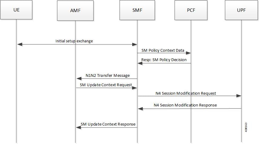
The SMF maintains the following statistics to track the total number of attempted, successful, and failed node-level and session-level requests.

  • SMF_SERVICE_STATS for the following procedure types:

    • upf_node_report_pdu_sess_rel

      attempted: Total number of attempted PDU session release requests triggered due to the node report.

      successful: Total number of successful PDU session release requests triggered due to the node report.

      failure: Total number of failed PDU session release requests triggered due to the node report.

    • upf_sess_report_gter_pdu_sess_rel

      attempted: Total number of attempted PDU session release requests triggered due to the session report “GTER”.

      successful: Total number of successful PDU session release requests triggered due to the session report “GTER”.

      failure: Total number of failed PDU session release requests triggered due to the session report “GTER”.

  • SMF_PROTOCOL_UDP_REQ_MSG_TOTAL for the following message types:

    • n4_node_report_req

      attempted: Total number of attempted N4 requests triggered due to the node report.

      successful: Total number of successful N4 requests triggered due to the node report.

      failure: Total number of failed N4 requests triggered due to the node report.

    • n4_session_report_req

      attempted: Total number of attempted N4 requests triggered due to the session report.

      successful: Total number of successful N4 requests triggered due to the session report.

      failure: Total number of failed N4 requests triggered due to the session report.

  • SMF_PROTOCOL_UDP_RES_MSG_TOTAL for the following message types:

    • n4_node_report_res

      attempted: Total number of attempted N4 responses triggered due to the node report.

      successful: Total number of successful N4 responses triggered due to the node report.

      failure: Total number of failed N4 responses due to the node report.

    • n4_session_report_res

      attempted: Total number of attempted N4 responses triggered due to the session report.

      successful: Total number of successful N4 responses triggered due to the session report.

      failure: Total number of failed N4 responses due to the session report.

  • SMF_DISCONNECT_STATS triggered for the following disconnect reasons:

    gtpu_peer_path_failure : This statistic is triggered when the session is deleted due to the node report.

    upf_sess_report_gter_pdu_sess_rel: This statistic is triggered when the session is deleted due to the session report.

The following is an example of the statistics:

Node Report SMF-service stats:

smf_service_stats{app_name="SMF",cluster="Local",data_center="DC",dnn="intershat",
emergency_call="false",instance_id="0",pdu_type="ipv4",
procedure_type="upf_node_report_pdu_sess_rel",qos_5qi="",rat_type="NR",
reason="",service_name="smf-service",status="attempted",up_state=""} 
smf_service_stats{app_name="SMF",cluster="Local",data_center="DC",dnn="intershat",
emergency_call="false",instance_id="0",pdu_type="ipv4",
procedure_type="upf_node_report_pdu_sess_rel",qos_5qi="",rat_type="NR",
reason="",service_name="smf-service",status="success",up_state=""} 1
 

Session Report SMF-service stats:

smf_service_stats{always_on="",app_name="smf",cluster="smf",data_center="unknown",
dcnr="",dnn="intershat",emergency_call="false",instance_id="0",pdu_type="ipv4",
procedure_type="upf_sess_report_gter_pdu_sess_rel",qos_5qi="",rat_type="NR",
reason="",service_name="smf-service",status="attempted",up_state=""} 1 
smf_service_stats{always_on="",app_name="smf",cluster="smf",data_center="unknown",
dcnr="",dnn="intershat",emergency_call="false",instance_id="0",pdu_type="ipv4",
procedure_type="upf_sess_report_gter_pdu_sess_rel",qos_5qi="",rat_type="NR",
reason="",service_name="smf-service",status="success",up_state=""} 1 

Node Report SMF-protocol stats:

smf_proto_udp_req_msg_total{app_name="smf",cluster="smf",data_center="unknown",
instance_id="0",message_direction="inbound",message_name="n4_node_report_req",
msgpriority="",service_name="smf-protocol",status="accepted",
transport_type="origin"} 15 
smf_proto_udp_res_msg_total{app_name="smf",cause="1",cluster="smf",
data_center="unknown",instance_id="0",message_direction="outbound",
message_name="n4_node_report_res",msgpriority="",service_name="smf-protocol",
status="accepted",transport_type="origin"} 15 

Session Report SMF-protocol stats:

smf_proto_udp_req_msg_total{app_name="smf",cluster="smf",data_center="unknown",
instance_id="1",message_direction="inbound",message_name="n4_session_report_req",
msgpriority="",service_name="smf-protocol",status="accepted",
transport_type="origin"} 43 
smf_proto_udp_res_msg_total{app_name="smf",cause="1",cluster="smf",
data_center="unknown",instance_id="1",message_direction="outbound",
message_name="n4_session_report_res",msgpriority="",service_name="smf-protocol",
status="accepted",transport_type="origin”} 

The SMF also maintains labels to track the number of session deletions due to the node report and session report types – GTER, SRIR, and SPTER.

For example, the label "LABEL_DISC_PDNREL_GTER_SESSION_REP" is added to track the session deletion due to the presence of GTER.

Support for Session Report Rejection Procedure

Feature Description

The SMF rejects the UPF-originated Session Report Request with a specific cause code during any mismatch in the charging configuration of SMF and UPF.

For any session report rejection by the SMF, the UPF locally purges the sessions. The SMF is unaware of the purging operation and continues to send the N4 message to the UPF. This action triggers the UPF to send “context not found” message to the SMF for the locally purged sessions.

This behavior impacts the UE experience and results in the loss of charging data. So, the current implementation of handling the session report errors is modified to avoid local purging of sessions on the UPF and also to support graceful clearing of sessions.

With this modification, the UPF ignores the Session Report Error Response. The SMF triggers the Session Deletion Request followed by the rejection of Session Report. The UPF responds to the delete request and clears the session gracefully.

The existing Failure Handling (FH) configuration introduces a new parameter “N4SessionReportReq” to control the UPF from locally purging the rejected sessions. This CLI also triggers the SMF to send a Session Deletion Request after the Session Report rejection.

Relationships

This feature involves implementing some behavioral changes to the SMF and the UPF. The new CLI configuration aids in controlling this behavior. For details on the UPF behavioral changes, see the UCC 5G UPF Configuration and Administration Guide.

Configuring FH Action for Handling Session Report Errors

This section describes how to define the parameter within the UPF failure handling configuration to gracefully handle the session report errors.

When the SMF rejects the Session Report Request message and the failure handling configuration includes the parameter, the SMF supports the following failure handling actions:

  • ignore : Ignores the error and does not take any further action

  • terminate : Terminates the session (Triggers the Session Deletion Request)

During this scenario, if the failure handling configuration is unavailable, the SMF does not initiate the Session Deletion Request.

configure 
   profile failure-handling profile_name 
      interface pfcp message N4SessionReportReq 
         cause-code cause_ID 
         action { ignore | terminate } 
         end 

NOTES:

  • profile failure-handling : Specifies the UPF profile that is associated with Failure Handling Template (FHT).

  • interface pfcp message N4SessionReportReq : Specifies the failure handling for N4 Session Report Request.

  • cause-code cause_ID : Specifies the error codes that the SMF receives in the failure response message from the UPF. cause_ID can be any integer from 2 through 255. The cause code value can be separated by either '-' or ',' or both. For example, cause-code 72-74,76,78-100

  • action { ignore | terminate } : Specifies the action to perform based on the error cause code received in the failure response message from the UPF.

    • ignore : Specifies to ignore the session.

    • terminate : Specifies to terminate the session.

Verifying the Feature Configuration

Use the show running-config CLI command to verify if the feature is enabled.

show running-config 

The following configuration is a sample output of the show running-config command:

show running-config profile failure-handling interface pfcp
profile failure-handling FH1
 interface pfcp message N4SessionEstablishmentReq
  cause-code pfcp-entity-in-congestion action retry-terminate max-retry 2
  cause-code system-failure action terminate
  cause-code service-not-supported action terminate
  cause-code no-resource-available action retry-terminate max-retry 3
  cause-code no-response-received action retry-terminate max-retry 1
  cause-code reject action terminate
 exit
 interface pfcp message N4SessionModificationReq
  cause-code mandatory-ie-incorrect action terminate
  cause-code session-ctx-not-found action terminate
  cause-code reject action terminate
 exit
 interface pfcp message N4SessionReportReq
  cause-code 69 action terminate
  cause-code 72-74,76,78-100 action terminate
 exit
exit
 

OAM Support

This section describes operations, administration, and maintenance information for this feature.

Statistics Support

The SMF supports the following disconnect reasons as part of “smf_disconnect_stats”:

  • smf_sess_pdn_rel_peer_request_reject — This disconnect reason is applicable for 4G and WiFi calls.

  • smf_sess_pdu_rel_peer_request_reject — This disconnect reason is applicable for 5G calls.

Outer Header Format

The SMF accepts the new format of the Outer Header information element (IE) from the UPF. The Packet Detection Rule (PDR) of Packet Forwarding Control Protocol (PFCP) session includes this IE. The Outer Header IE is present in the N4 Session Establishment Request message sent over the Sx interface. The version 16.4.0 of 3GPP TS 29.244 specification defines the format of this IE.

The following table identifies the encoding format of Outer Header Creation Description field. It takes the form of a bitmask where each bit indicates the outer header to be added to the outgoing packet. Note that the receiver (SMF) ignores the spare bits.

Octet / Bit Outer Header Created in the Outgoing Packet
5/1 GTP-U/UDP/IPv4
5/2 GTP-U/UDP/IPv6
5/3 UDP/IPv4
5/4 UDP/IPv6
5/5 IPv4
5/6 IPv6
5/7 C-TAG
5/8 S-TAG
6/1 N19 Indication
6/2 N6 Indication
6/3 TCP/IPv4
6/4 TCP/IPv6

NOTE:

  • Currently, the UP or UPF does not support the following values of Outer Header Creation Description:

    • IPv4

    • IPv6

    • C-TAG

    • S-TAG

    • N19 Indication

    • N6 Indication

  • The third and fourth bits of sixth Octet (that is, 6/3 and 6/4) are spare bits (that is, not part of 3GPP TS) used for LI over TCP.


Important

The SMF and the UPF must support the same version of Outer Header IE for a successful session establishment.