Virtual Wireless LAN Controller Deployment Guide 8.2
Available Languages
Contents
- Introduction
- New Features in 8.2
- Features Not Supported on Cisco Virtual WLCs ( as of 8.2.100.0 and below)
- High Availability Features not Supported
- Hardware Requirement for Virtual Wireless LAN Controller Version 8.2
- Download Cisco Virtual Wireless LAN Controller
- VMware Virtual Machine
- VMware Prerequisite for Hosting Virtual WLC (vWLC)
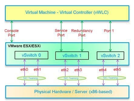
- Virtual Controller Virtual Interfaces
- Switch Interface Configuration Connected to UCS Server
- Deploying vWLC OVA
- Optional Virtual Controller Console Port
- vWLC Simplified Setup
- Linux Kernel-based Virtual Machine (KVM)
- KVM Prerequisite for Hosting Virtual WLC (vWLC)
- Installing Fedora OS
- Updating Fedora OS
- Installing KVM and openvswitch with Supporting Packages
- Verifying the Installation of KVM
- Network Configuration
- Creating a Bridge and Mapping it to Port (Ethernet Interface)
- Viewing the Bridge Mapping
- Creating XML Files
- Allowing CDP Packets to Forward from Open vSwitch
- Viewing the Virtual Network
- Deleting the Default Network
- Creating Virtual Network
- Viewing the Virtual Network
- Starting the Virtual Network
- Installing vWLC Using Virtual Machine Manager (VMM) in Fedora
- Accessing vWLC's Console in Fedora
- Installing vWLC and KVM with Ubuntu
- One Time Network Configuration on Ubuntu
- Launching vWLC Using VMM
- Accessing vWLC in VMM
- Installing vWLC and Host Linux with Suse Linux
- Install KVM and Supporting Packages in Suse
- Enabing SSH
- Network Configuration
- Creating a Bridge and Mapping it to Port (Ethernet Interface)
- Viewing the Bridge Mapping
- Creating XML Files
- Starting Open vSwitch
- Configuring Open vSwitch to Start When the System Boots
- Starting libvirt
- Allowing CDP Packets to Forward from Open vSwitch
- Viewing the Virtual Network
- Deleting the Default Network
- Creating Virtual Network
- Viewing the Virtual Network
- Starting the Virtual Network
- Installing vWLC Using VMM
- RTU Licensing
- RTU Licensing Using CLI
- Smart Licensing
- Smart Licensing Using Web GUI
- Enable Smart Licensing and Register Device
- Virtual Controller Management with Cisco Prime 3.0
- Upgrading the Virtual Controller
Introduction
Prior to release 7.4, WirelessLAN (WLAN) controller software ran on dedicated hardware you were expected to purchase. The Virtual WirelessLAN Controller (vWLC)runs on general hardware under an industry standard virtualization infrastructure. The vWLC is ideal for small and mid-size deployments with a virtual infrastructure and require an on-premises controller. Distributed branch environments can also benefit with a centralized virtual controller with fewer branches required (up to 200).
vWLCs are not a replacement of shipping hardware controllers. The function and features of the vWLC offer deployment advantages and benefits of controller services where data centers with virtualization infrastructure exist or are considered.
Advantages of the vWLC
New Features in 8.2
The new features in 8.2 are:
Increased scale support for Small and Large vWLC Deployment in the private cloud for simplified operations, flexible deployments and pay as you grow model
Support for Smart Licensing for vWLC - Provide cloud based license visibility on what the customer owns and what the customer is using, this improves visibility, reduced activation complexity, and optimal utilization.
Features Not Supported on Cisco Virtual WLCs ( as of 8.2.100.0 and below)
- Internal DHCP server
- TrustSec SXP
- Access points in local mode
- Mobility/Guest Anchor
- Multicast
- Cisco WLC integration with Lync SDN
FlexConnect Central Switching
Note
FlexConnect Local Switching is supported.
Note
FlexConnect local-switched multicast traffic is bridged transparently for both wired and wireless on the same VLAN. FlexConnect access points do not limit traffic based on IGMP or MLD snooping.
High Availability Features not Supported
Note
When an AP moves from one vWLC to another, it may refuse to join the second vWLC. It occurs when the server hardware fails, or a new instance of vWLCs are created. It is recommended to implement server mirroring scheme at the VMware level such as vMotion or some orchestrator. It is highly recommended to retain a snapshot of the VM instance, one from the mobility domain to which access points have joined previously. Then use the snapshot to start the vWLC instance. Access points then join the vWLC. This method can be also be used for priming access points instead of a physical controller.
Download Cisco Virtual Wireless LAN Controller
Download the latest 8.x software from: https://software.cisco.com/download/type.html?mdfid=284464214&i=rm
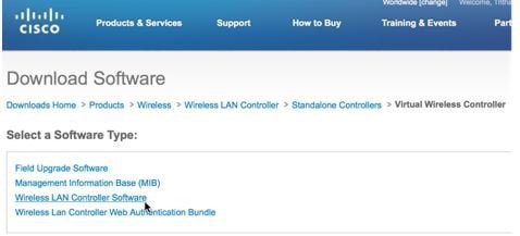
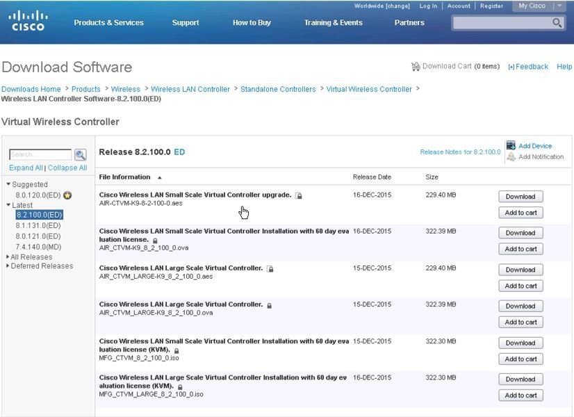
For software release 8.2, virtual wireless controllers will be offered in 2 types of deployment, SMALL or LARGE, in *aes (software upgrade) or *.ova (VMware) or *.iso (KVM) format. Refer to the HW requirement needed to support the target deployment.
Software upgrade is *.aes format.
Cisco Wireless LAN Small Scale Virtual Controller upgrade
AIR-CTVM-K9-8-2-100-0.aes
Cisco Wireless LAN Large Scale Virtual Controller
AIR_CTVM_LARGE-K9_8_2_100_0.aes
To upgrade existing vWLC, use the *.aes software and go through the normal upgrade process of WLCs.
Note
vWLC upgrade supports only of the same type (e.g. Small to Small, Large to Large). Mixed is not supported (e.g. Small to Large, or Large to Small).
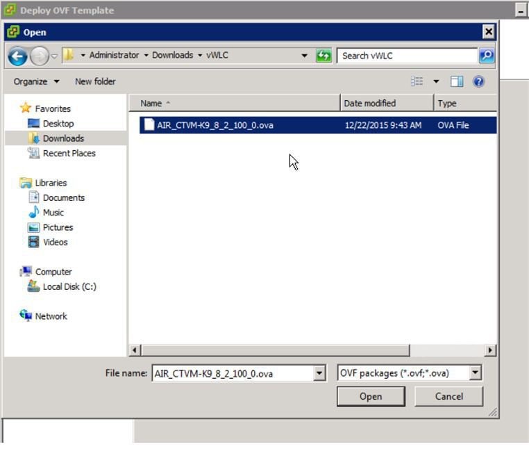
For installing NEW virtual wireless controllers on VMware, use *.ova.
Cisco Wireless LAN Small Scale Virtual Controller Installation with 60 day evaluation license
AIR_CTVM-K9_8_2_100_0.ova
Cisco Wireless LAN Large Scale Virtual Controller
AIR_CTVM_LARGE-K9_8_2_100_0.ova
For installing NEW virtual wireless controllers on KVM, use *.iso.
Cisco Wireless LAN Small Scale Virtual Controller Installation with 60 day evaluation license (KVM)
MFG_CTVM_8_2_100_0.iso
Cisco Wireless LAN Large Scale Virtual Controller Installation with 60 day evaluation license (KVM)
MFG_CTVM_LARGE_8_2_100_0.iso
VMware Virtual Machine
This document is an update for vWLC based on the CUWN 8.2 software release and the support for VMware ESX. VMware is supported in Cisco Wireless Release 7.4 and later releases.
VMware Prerequisite for Hosting Virtual WLC (vWLC)
Following are the VMware prerequisites for hosting vWLC:
- Minimum of 2 G (small) or 8 G (large) memory
- Minimum of 1 vCPU (small) or 2 vCPU (large)
- Minimum of 2 network interfaces
- Required storage of 8 G
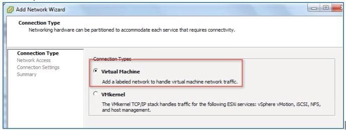
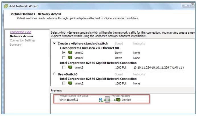
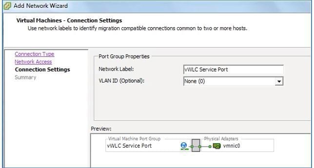
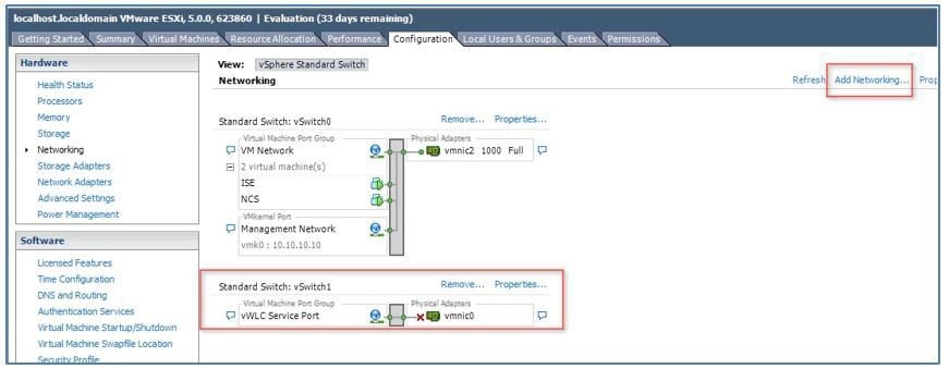
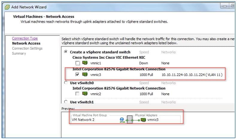
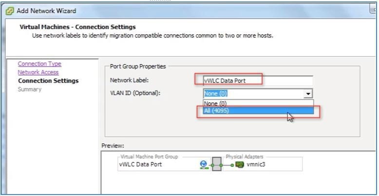
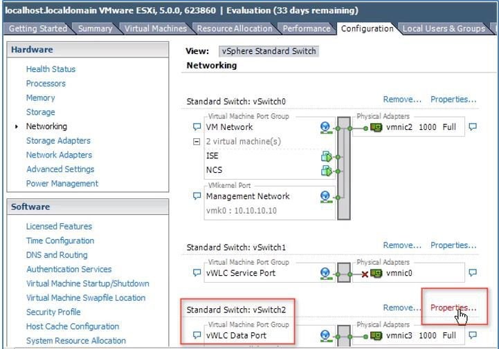
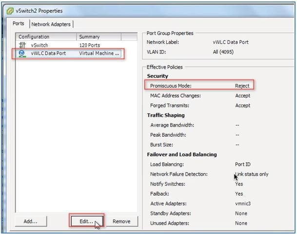
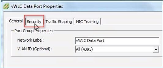
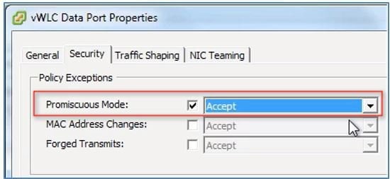
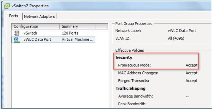
In ESXi, configure the appropriate networking needed to support vWLC. The recommendation is to use a trunk for Dataport, and an optional access port for the Service Port*, such as the example below:
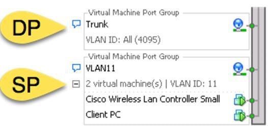
Note
* vWLC service port can be used to enable the feature of Simplified initial (or day 0 Controller Provisioning setup) for Cisco WLCs. This provides an alternate setup using a client browser and following a minimal set of steps. By using the simplified setup, best practices defaults including RF parameter optimization and network profiles are enabled.
Switch Interface Configuration Connected to UCS Server
ProcedureA sample configuration of the Cisco Catalyst interface connection to the ESXi server for the virtual switch as trunk interface. Management interface can be connected to an access port on the switch.
interface GigabitEthernet1/1/2
description ESXi Management
 switchport access vlan 10
 switchport mode access
!
interface GigabitEthernet1/1/3
 description ESXi Trunk
 switchport trunk encapsulation dot1q
 switchport mode trunk
end
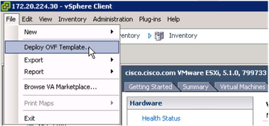
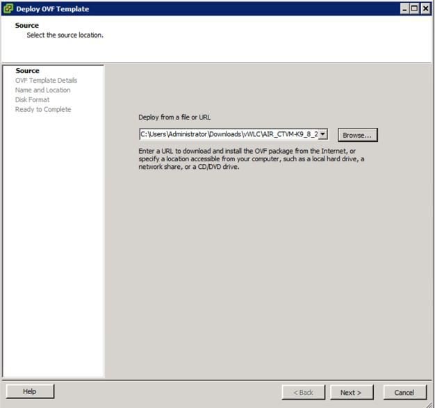
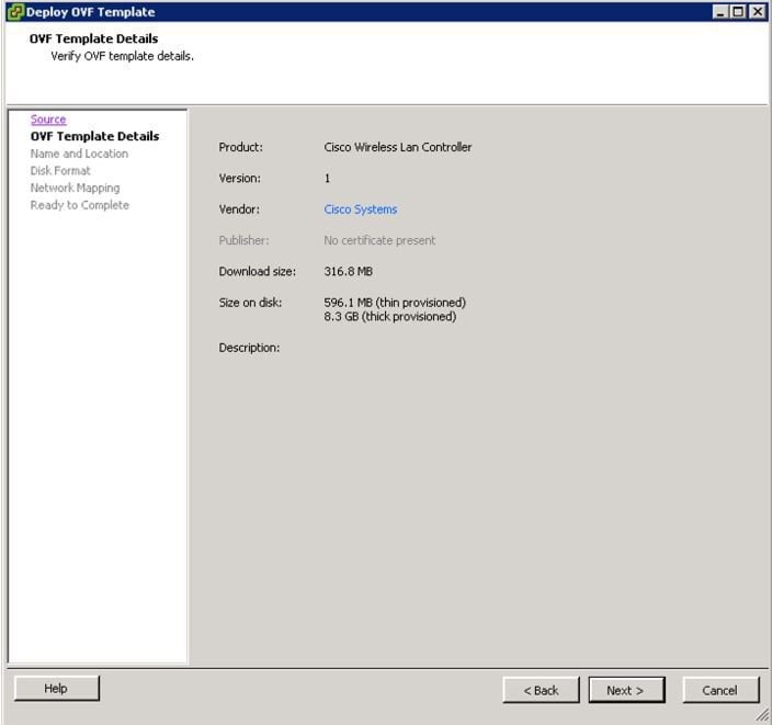
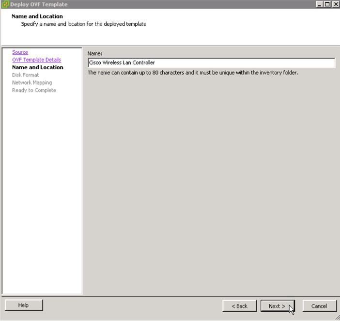
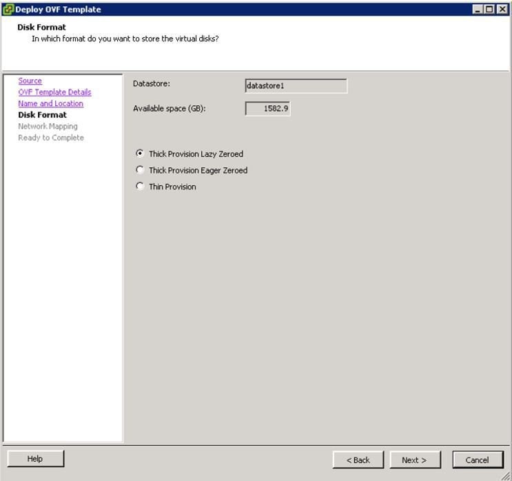
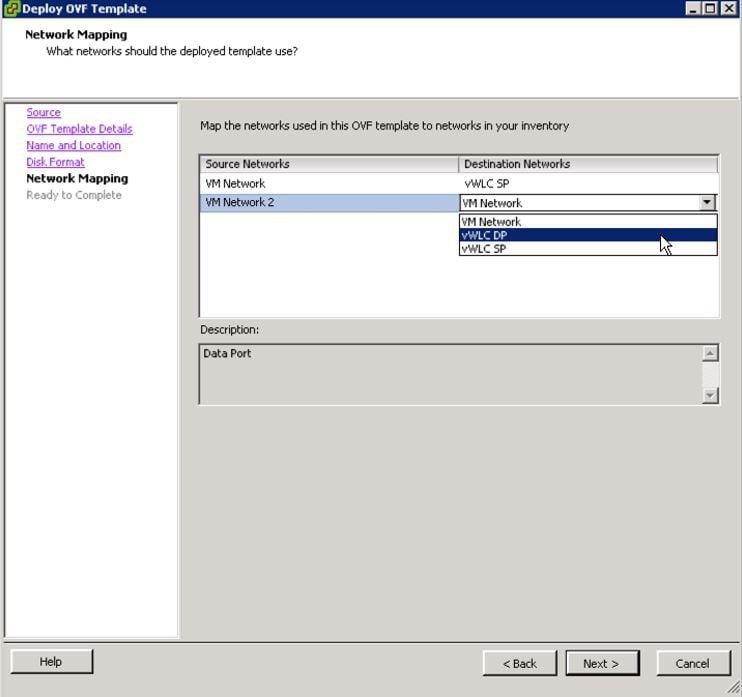
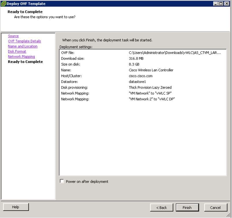
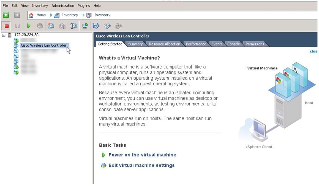
Deploying vWLC OVA
Procedure
Optional Virtual Controller Console Port
ProcedureThe console port will give access to console prompt of Wireless LAN Controller. So the VM can be provisioned with serial ports to connect to these. In the absence of serial ports, the VSphere Client Console will get connected to the console on vWLC.
VMWare ESXi supports a virtual serial console port that can be added to vWLC VM. The serial port can be accessed in one of the following two ways:
Physical Serial Port on the Host: vWLC's virtual serial port will be mapped to the hardware serial port on the server. This option is limited to the # of physical serial port(s) on the host, if in a multi-tenant vWLC scenario, this may not be ideal.
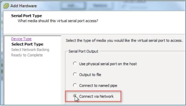
Connect via Network: vWLC's virtual serial port can be accessed using telnet session from a remote machine to a specific port allocated for the VM on hypervisor. For example, if the hypervisor's IP address is 10.10.10.10 and port allocated for a vWLC VM is 9090, using "telnet 10.10.10.10 9090", just like accessing a physical WLC's console using a Cisco terminal server, vWLC's serial console can be accessed.
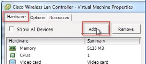
Step 1 In the vWLC Hardware tab, click 'Add'.
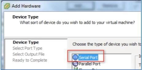
Step 2 Select Serial Port, and click Next.
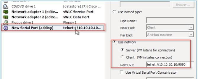
Step 3 In this scenario, select 'Connect via Network'. Click Next.
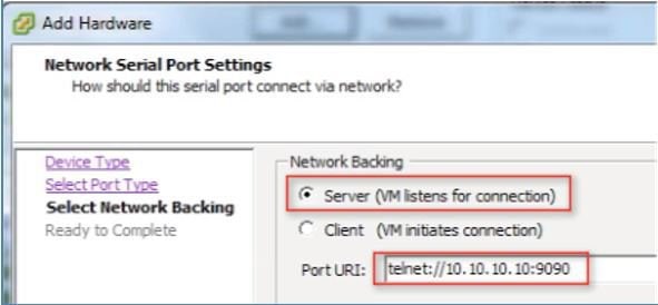
Step 4 Select Network Backing > Server (VM listens for connection) Step 5 Port URI: telnet://<host>:<port> e.g. telnet://10.10.10.10:9090
Step 6 Click Next to review options, and click Finish.
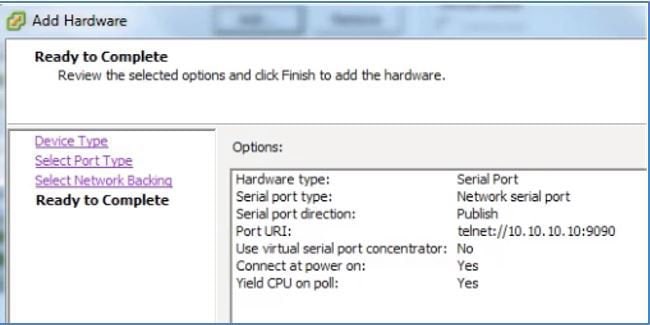
Step 7 Click OK to complete the configured settings.
To enable for the serial via network, ESX must be configured to allow for such requests.
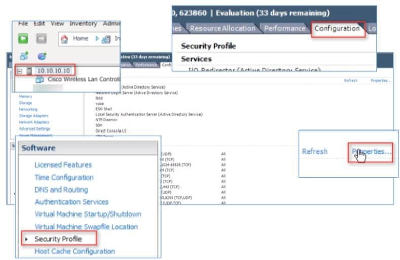
Step 8 Navigate to the ESX > Configuration > Software > Security Profile, and click Properties.
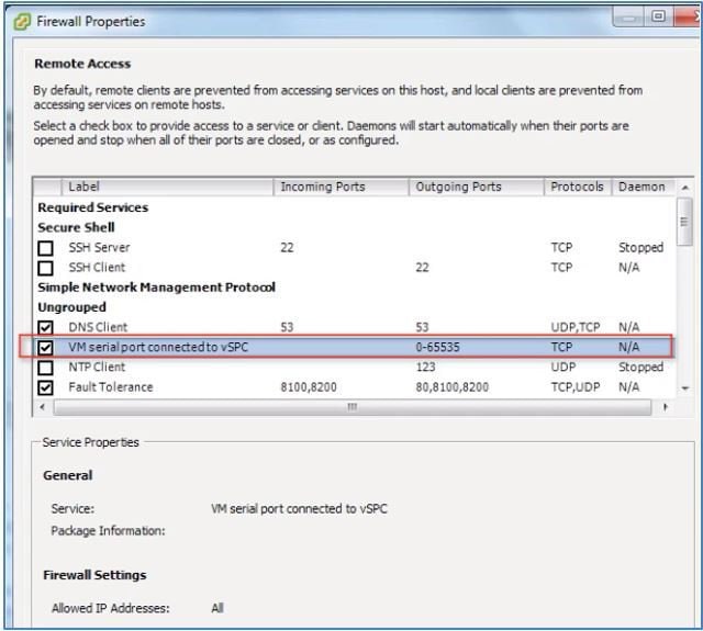
Step 9 In the Firewall Properties > select / check VM serial port connected to vSPC, and click OK to finish with settings. Starting Up the vWLC
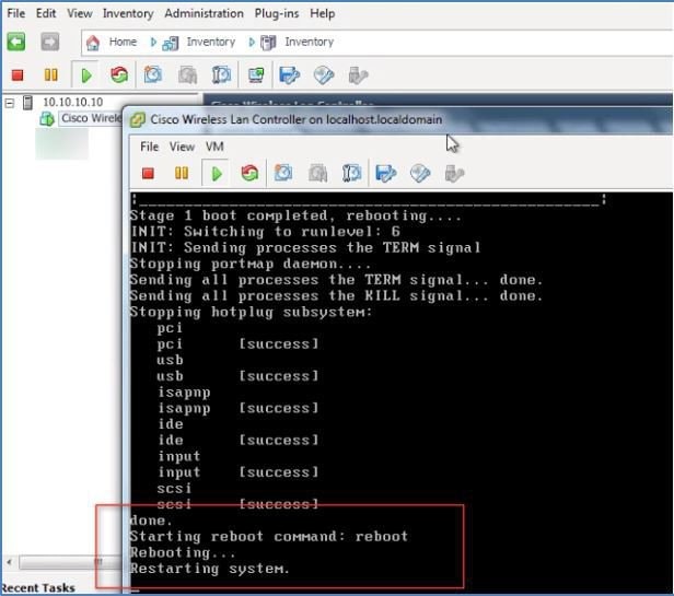
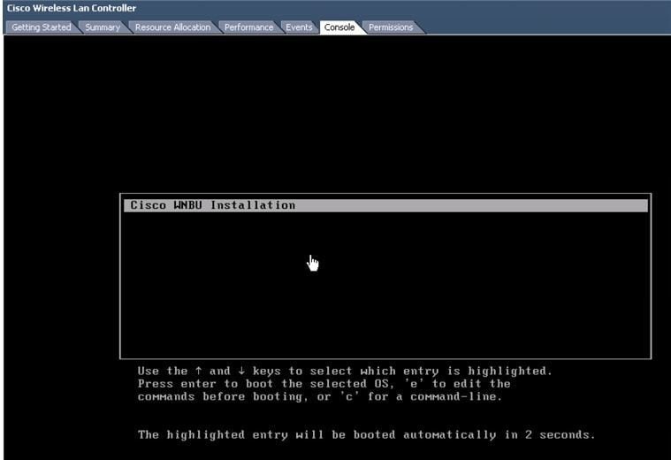
Step 10 Start the virtual WLC, and select console to observe the first-time installation process.
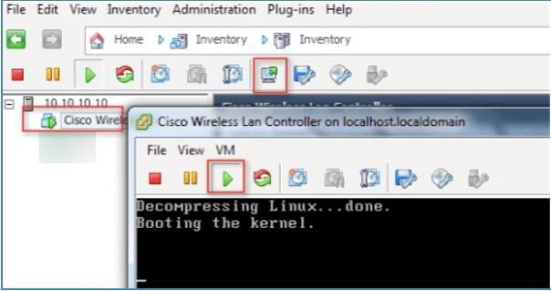
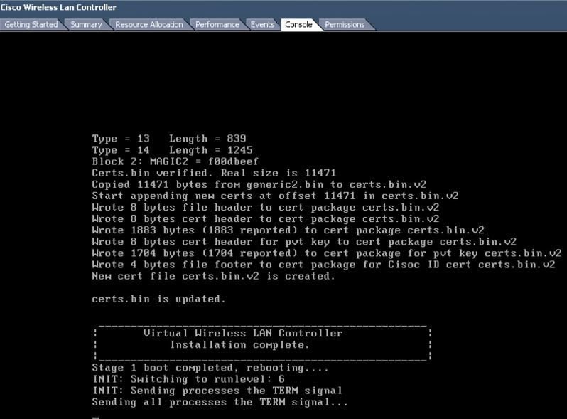
Step 11 Monitor progress until the VM console shows that the vWLC has restarted (this is automatic).
Step 12 At this time, open telnet session to vWLC such as in the example below.
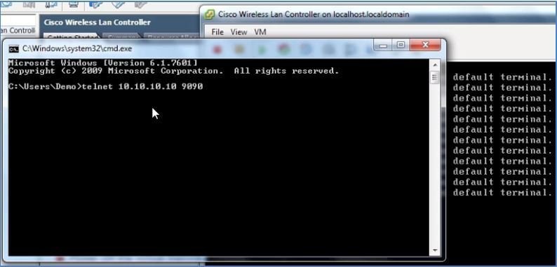
Step 13 Telnet session will now manage the console to vWLC.
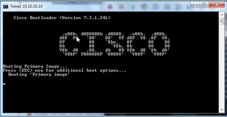
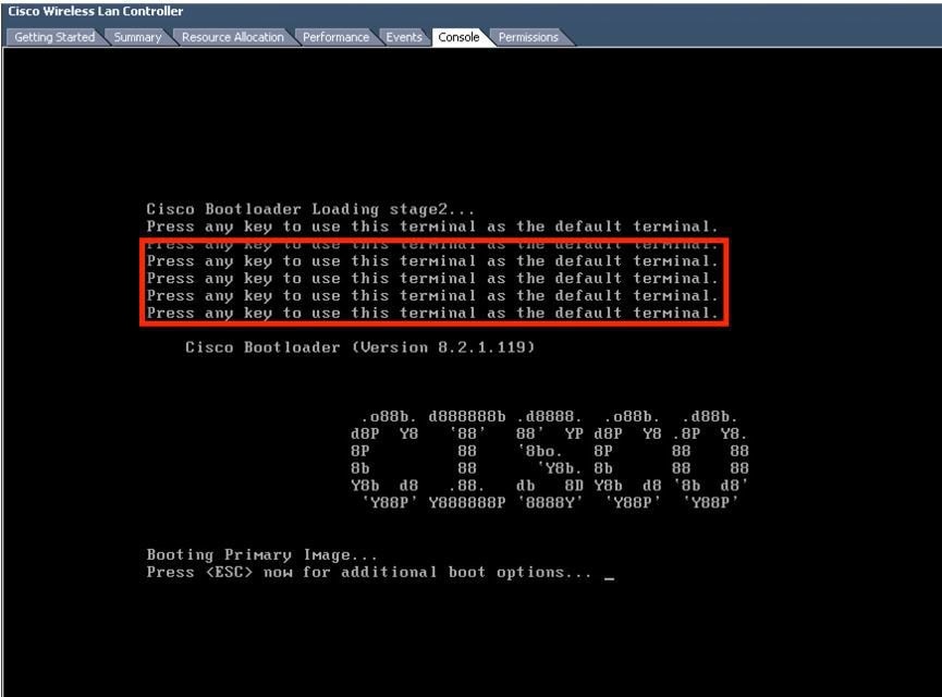
Note Only 1 mode of console can be operational at any time, such as VM console (by key-interrupt at startup), or serial console (physical/network). It is not possible to maintain both at the same time.
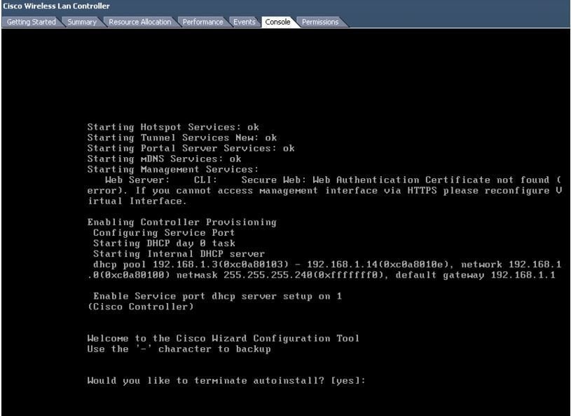
Step 14 Continue to wait until the vWLC has fully come online and prompt to start the configuration tool wizard.
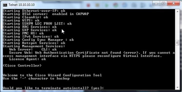
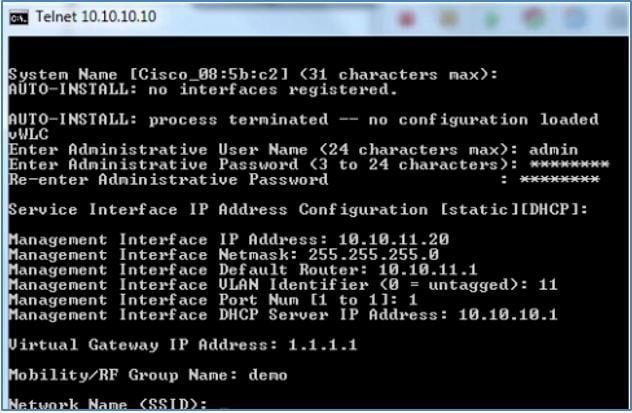
Step 15 Configure the management interface address / mask / gateway. Configure Management Interface VLAN ID if tagged. Continue with the remainder.
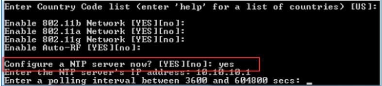
Step 16 Similar to all network device(s), it is crucial and very important to configure NTP. The virtual controller must have correct clock as it is possible to have an incorrect clock on the ESX host, or from manual configuration, which may result in access points not joining in the process.
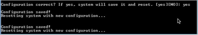
Step 17 Complete the configuration and allow the vWLC to Reset.
Step 18 A suggestion is to ping the vWLC management interface to ensure that it has come online. Log into the vWLC.
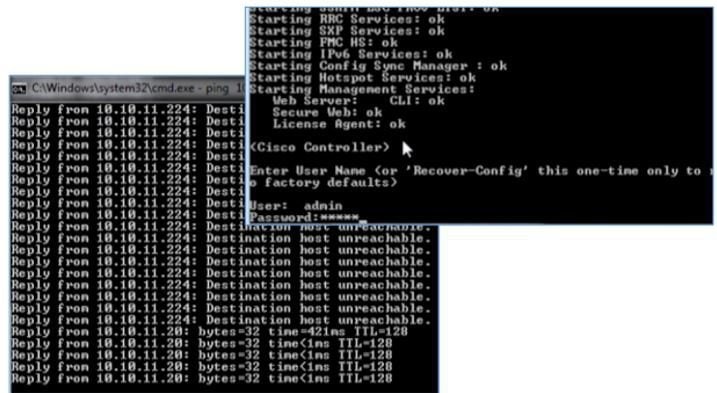
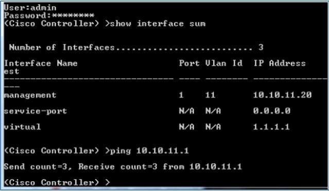
Step 19 You can perform 'show interface summary' and ping the gateway from the vWLC.
Step 20 Connect to vWLC management using a web browser
vWLC Simplified Setup
ProcedureAn alternative to configuring the vWLC using CLI through the VMware console, is using the simplified controller provisioning feature, applicable both in VMware or KVM deployment. As mentioned early in this guide, any client PC wired connected accessing the network mapped to the vWLC Service Port will be able to use this feature. This feature is enabled after first boot from an non-configured vWLC, temporarily provides DHCP service on the Service Port segment, and assign PC clients a limited network address. The client PC can connect to the vWLC using a web browser.
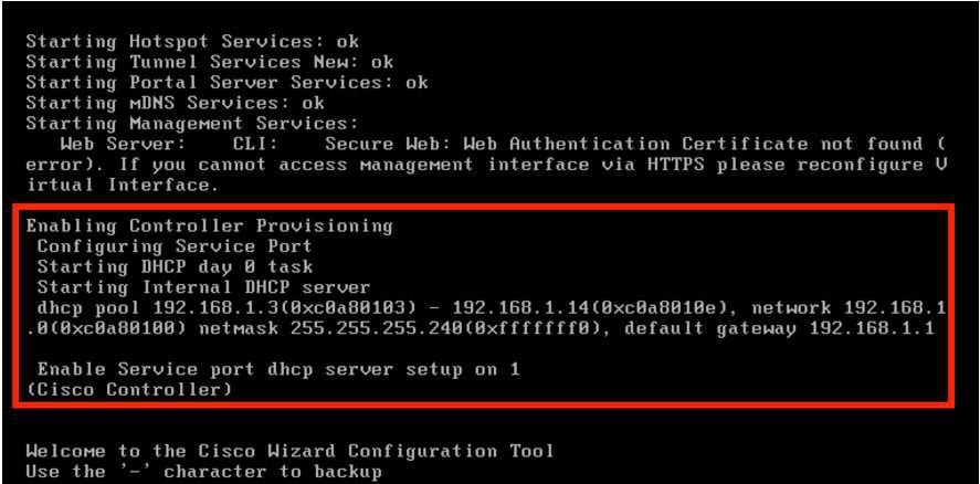
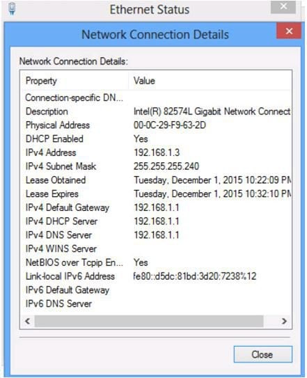
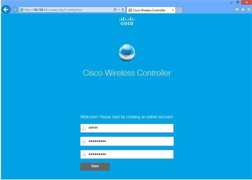
Step 1 With a client PC connected to the vWLC mapped Service Port, it gets an address from a limited range of 192.168.1.3 through 192.168.1.14. The vWLC is assigned a fixed 192.168.1.1.
Step 2 From the client PC, open a browser and connect to http://192.168.1.1, the Simplified Setup wizard will navigate the admin through the minimal steps required to fully configure vWLC. The first step is creating the admin account, provide the admin username and password, then click Start
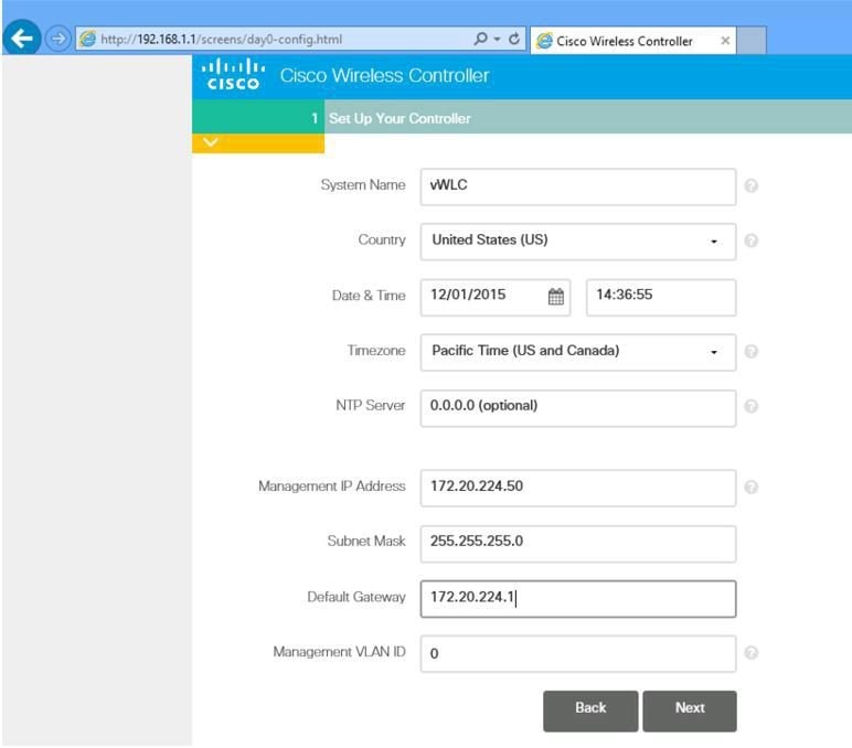
Step 3 In step 1 of the simplified setup wizard, set up the vWLC with a system name, country, date/time (automatically taken from client PC clock) and NTP server. Also, define the management IP address, subnet mask, gateway and VLAN for the management interface. This assignment needs to be configured and available on the Data Port (trunk) from the initial VMware/KVM setup of network interfaces. Click Next.
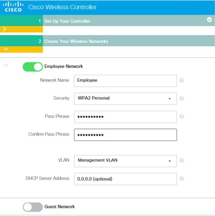
Step 4 In step 2, create the wireless network (SSID), security, and network/VLAN assignment as required. Optional is the inclusion of a Guest Network setup, a quick and simple step to add secure guest access with separate network and access method for guests. Click Next.
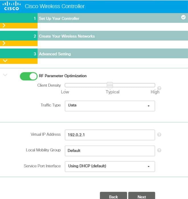
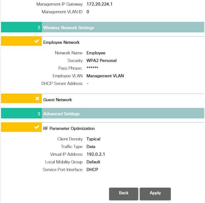
Step 5 In step 3 of the simplified setup, an admin can optimize the WLC setup for intended RF use, and taking advantages of Cisco Wireless LAN Controller best practices defaults. Click Next to finalize the setup.
Note Cisco best practices are continuously updated at this location:http://www.cisco.com/c/en/us/td/docs/wireless/technology/wlc/82463-wlc-config-best-practice.html
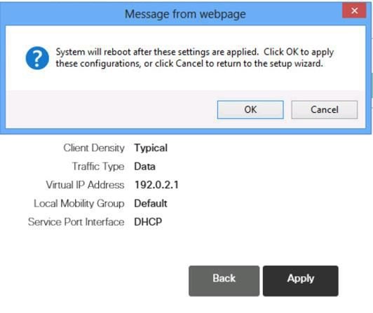
Step 6 The simplified setup wizard will summarize the detail of configuration. Click apply to save and reboot the vWLC.
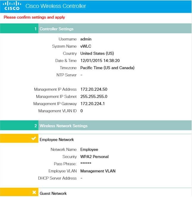
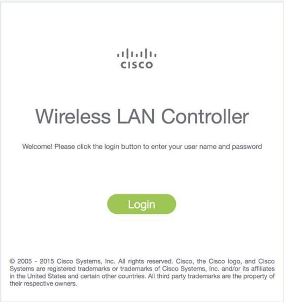
Step 7 Once the vWLC reboots, it will disable the simplified setup feature and use of the Service Port. Operation is dedicated to the Data Port, and in effect using the management interface and any dynamic interfaces defined. Log in through the assigned management IP address of the vWLC to continue.
Linux Kernel-based Virtual Machine (KVM)
This document is an update for vWLC based on the CUWN 8.2 software release and the support for Linux Kernel-based Virtual Machine(KVM). KVM is supported in Cisco Wireless Release8.1.102.0 and later releases.
Note
After KVM is deployed, it is recommended that you do not downgrade to a Cisco Wireless release that is older than Release 8.1.102.0.
KVM Prerequisite for Hosting Virtual WLC (vWLC)
Following are the KVM prerequisites for hosting vWLC:
- Minimum of 2 G (small) or 8 G (large) memory
- Minimum of 1 vCPU
- Minimum of 2 network interfaces
- Required storage of 8 G
- Network device model is "virtio"
- The physical devicesconnected to Open vswitch bridgeshould not have any IP addresses configured on it.
For more information, refer to http://www.linux-kvm.org/page/FAQ
Installing Fedora OS
Procedure
Step 1 Install Fedora21 or later. Click the followinglink to downloadFedora. Step 2 After installing Fedora, configure IP address to go to internet. In this scenario, two dedicated Linuxinterfaces/ports are used for vWLC.
Step 3 Find out your interface using ifconfig. Example:
First interface - for uplink (service-port of WLC); no IP addressis required to this interface but should be connected and up.
Second interface - for WLC Management interface; no IP address is required to this interfacebut should be connected and up.
Third or fourth interface - for Linux accessibility; provide IP address to this interface, so that there is a network connectivity to the Linux box.
Note By default, KVM uses first interface as service-port for vWLC.
Step 4 Configure IP address to the third or fourth interface to access Linux and access internet to get update. vi /etc/sysconfig/network-scripts/ifcfg-enp2s0f3
Note You will need to change BOOTPROTO from DHCP to static and add IPADDR, NETMASK, BROADCAST, and NETWORK variables. It is recommended to choose the static IP address.
Example
NM_CONTROLLED="yes"
BOOTPROTO=static
DEVICE=eth1
ONBOOT=yes
IPADDR=192.168.8.248
NETMASK=255.255.255.0
BROADCAST=192.168.8.255
NETWORK=192.168.8.0
GATEWAY=192.168.8.1
TYPE=Ethernet
PEERDNS=no
Step 5 Save the file. OR
ifconfig <interface_name> <IP_address>
ifconfig <interface_name> netmask <netmask_address>
ifconfig <interface_name> broadcast <broadcast_address>
OR
ifconfig <interface_name> <IP_address> netmask <netmask_address> broadcast <broadcast_address>
Note Configure proxy and DNS information if required. Make sure internet is accessible after configuration.
Updating Fedora OS
Procedure
Step 1 Update Fedora OS: yum install updateStep 2 Install GUI: yum install @gnome-desktop -yStep 3 Install VNC server, http://www.namhuy.net/3134/install-vnc-server-on-fedora-20.html: yum install tigervnc-server -yStep 4 Install x11: yum groupinstall "X Software Development"
Network Configuration
Creating a Bridge and Mapping it to Port (Ethernet Interface)
ovs-vsctl add-br ov_10nw
ovs-vsctl add-port ov_10nw enp2s0f0
ovs-vsctl add-br ov_9nw
ovs-vsctl add-port ov_9nw en
The bridge name must be the same as created in the XML file.
Viewing the Bridge Mapping
ovs-vsctl showExample:
[root@localhost ~]# ovs-vsctl show
099e8b7e-bf00-4071-be62-ec55f9b543cc
Bridge "ov_9nw"
Port "ov_9nw"
Interface "ov_9nw"
type: internal
Port"enp2s0f1" Interface
"enp2s0f1"
Bridge "ov_10nw"
Port "ov_10nw"
Interface "ov_10nw"
type: internal
Port"enp2s0f0" Interface
"enp2s0f0"
ovs_version: "2.3.1-git3282e51"
Creating XML Files
Create two XML files; one for service-nw (10nw) and the other for management (9nw).
Example:
10nw_eth0_ov.xml
9nw_eth1_ov.xml
Both XML files containVLAN information based on the network, or based on what you want to allow.
Example: To Allow All VLANs
<network>
<name>10-nw</name>
<forward mode='bridge'/>
<bridge name='ov_10nw'/>
<virtualport type='openvswitch'/>
<portgroup name='vlan-any' default='yes'>
</portgroup>
</network>
The bridge name must be the same as created during "ovs-vsctl" command.
If only specific VLANs need to be allowed, use the following format:
<network>
<name>ov-nw</name>
<forward mode='bridge'/>
<bridge name='bridge_1'/>
<virtualport type='openvswitch'/>
<portgroup name='all_vlans' default='yes'>
</portgroup>
<portgroup name='vlan-152-untagged'>
<vlan>
<vlan mode='native-untagged'/>
<tag id='152'/>
</vlan>
</portgroup>
<portgroup name='vlan-153'>
<vlan>
<tag id='153'/>
</vlan>
</portgroup>
<portgroup name='two-vlan'>
<vlan trunk='yes'>
<tag id='152'/>
<tag id='153'/>
</vlan>
</portgroup>
</network>
In the above configuration:
portgroup name='all_vlans', allows all VLANs.
portgroup name='vlan-152-untagged', allows only untagged VLAN that is 152.
portgroup name='vlan-153', allows only 153 VLAN.
portgroup name='two-vlan', allows only two VLANs,that is, 152 and 153.
Allowing CDP Packets to Forward from Open vSwitch
ovs-vsctl set bridge ov_9nw other-config:forward-bpdu=trueStarting the Virtual Network
virsh net-start <network_name_that is in the list>Example:
[root@localhost ~]# virsh net-list --all
Name State Autostart Persistent
-----------------------------------------------------
default inactive no yes
[root@localhost ~]# virsh net-undefine default
Network default has been undefined
[root@localhost ~]# virsh net-define 10nw_eth0_ov.xml
Network 10-nw defined from 10nw_eth0_ov.xml
[root@localhost ~]# virsh net-define 9nw_eth1_ov.xml
Network 9-nw defined from 9nw_eth1_ov.xml
[root@localhost ~]# virsh net-list --all
Name State Autostart Persistent
-----------------------------------------------
10-nw inactive no yes
9-nw inactive no yes
[root@localhost ~]# virsh net-start 10-nw
Network 10-nw started
[root@localhost ~]#
[root@localhost ~]# virsh net-start 9-nw
Network 9-nw started
[root@localhost ~]# virsh net-list --all
Name State Autostart Persistent
-------------------------------------------
10-nw active no yes
9-nw active no yes
Installing vWLC Using Virtual Machine Manager (VMM) in Fedora
ProcedureTo install vWLC using VMM in Fedora, perform the following steps:
Note
Console to Fedora. GUI is required for VMM.
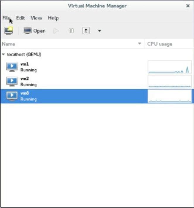
Step 1 Open the terminal (command prompt). Step 2 Execute the commandvirt-manager. The Virt Manager(VMM) pop-up window appears.
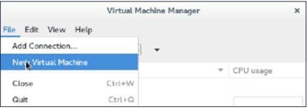
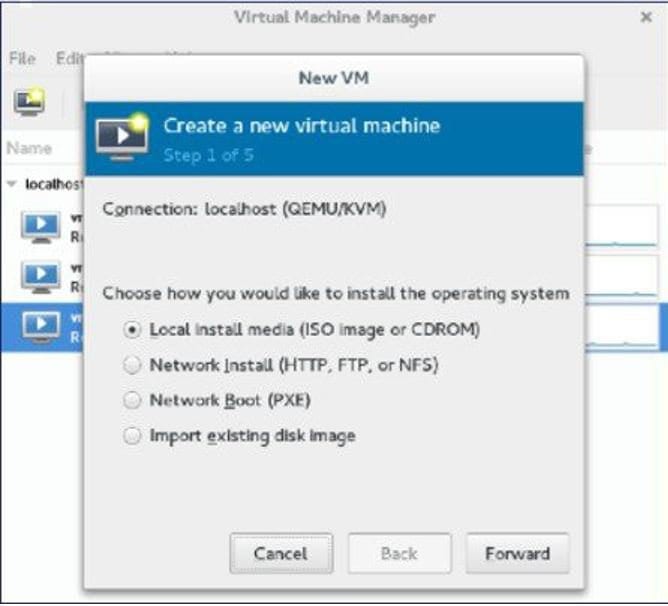
Step 3 Create a new virtual machine (VM).
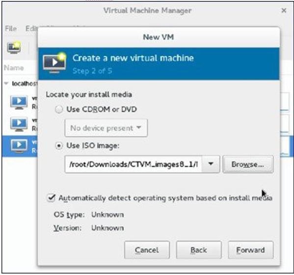
Step 4 Select the path.
Step 5 Select the ISO file of vWLC.
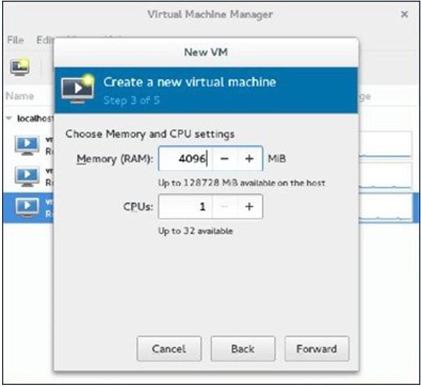
Step 6 Select the memory and CPU.
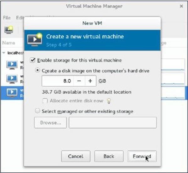
Step 7 Select the disk space.
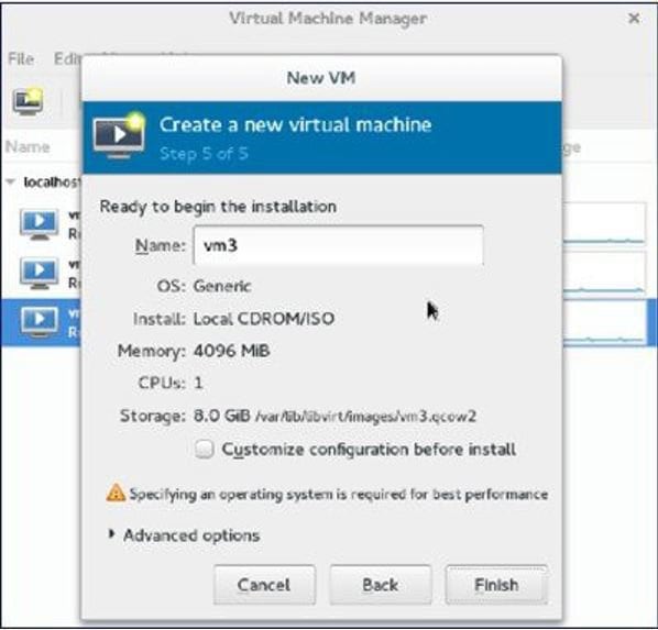
Step 8 Name the VM.
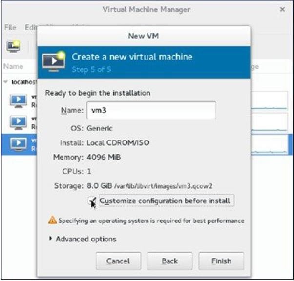
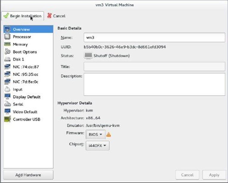
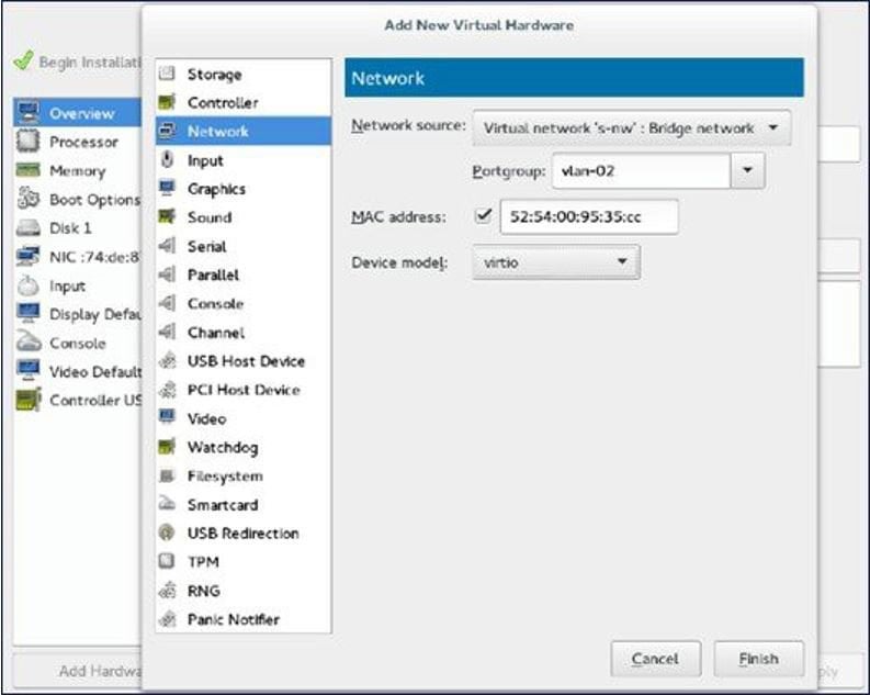
Step 9 Check the Customize configuration before install check box and then click Finish. (This helps to configure other options)
Step 10 Click Add Hardware. The Add New Virtual Hardware window appears.
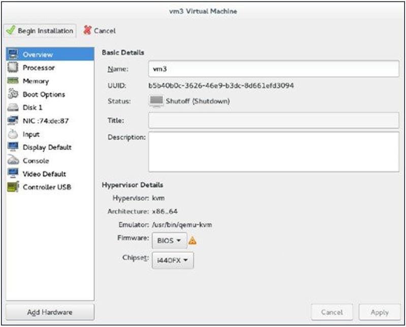
This window helps you to configure service port, management interface, and serial connection:
Step 11 Click Begin Installation.
Step 12 Wait for WLC prompt for initial configuration.
Accessing vWLC's Console in Fedora
Procedure
Step 1 From the terminal, execute the following command: virsh console <vm_name eg. vm1>Step 2 Reboot vWLC through virt-manager. To find out the vnet mapped to vWLC, execute the following command on vWLC:
show interface detail management
Note Match the last six octet with "ifconfig" output.
This is how, you get your targeted "vnet", if there are multiple vWLCs configured.
Installing vWLC and KVM with Ubuntu
Procedure
Step 1 Install Ubuntu Server 13.10 or later, select virtualization module/package during installation. Step 2 Install QEMU/KVM/Open vSwitch packages: apt-get install qemu-kvm qemu-utils uml-utilities bridge-utils socat vnc4server vncviewer apt-get install kvm libvirt-bin virtinst apt-get install openvswitch-controller openvswitch-switch openvswitch-datapath-sourceStep 3 Start the open vswitchservice. service openvswitch-switch startStep 4 Reboot the system.
One Time Network Configuration on Ubuntu
Procedure
Step 1 Create two open vswitch bridges and map eth0, eth1 to the corresponding bridges: ovs-vsctl add-br ovsbr0 [bridge name] ovs-vsctl add-port ovsbr0 eth0 ovs-vsctl add-br ovsbr1[bridge name] ovs-vsctl add-port ovsbr1 eth1 ovs-vsctl set bridge ovsbr1 other-config:forward-bpdu=true Required for CDP packets forwarding from Open Vswitch]Step 2 To define a management network, create an XML file [mgmt.xml] as follows: <network> <name>VM-Mgmt-Nw</name> <forward mode='bridge'/> <bridge name='ovsbr'/> <virtualport type='openvswitch'/> <!-- If the linux host port[For eg, eth1] is connected in trunk mode to the downstream switch[which is also connected to the openvswitch bridge ovsbr], then by choosing the following portgroup,traffic from all vlan is passed up to the vWLC. The management interface should be in vlan tagged mode. And multiple interfaces can also be created with different vlans. If the linux host port is connected in untagged mode to the downstream switch, then on choosing this portgroup,untagged frames are passed up to the vWLC. Hence management interface has to be untagged. --> <portgroup name='default-portgroup' default='yes'> </portgroup> <!-- If the linux host port is connected in trunk mode to the downstream switch [which is also connected to openvswitch bridge ovsbr],and if only certain vlans are to be allowed, choose this portgroup. Uncomment the following portgroup and edit the tag ids to the vlans allowed. You are free to add as many vlan ids as needed. --> <!-- <portgroup name='Management-Portgroup'> <vlan trunk='yes'> <tag id='4092'/> <tag id='4093'/> </vlan> </portgroup> --> </network>
Note Edit the vlan tags as per requirement.
Step 3 Run the following commands to create the management network: virsh net-define mgmt.xml virsh net-start VM-Mgmt-NetworkStep 4 Repeat step 2 for creating a service port network. To define the service port network, create an XML file [service.xml] as follows: <network> <name>VM-SP-Nw</name> <forward mode='bridge'/> <bridge name='ovsbr'/> <virtualport type='openvswitch'/> <!-- If this portgroup is chosen, it is presumed that the linux host port [For eg :eth0, connected to the openvswitch bridge "ovsbr"] is connected in access mode to the neighboring switch. --> <portgroup name='default-portgroup' default='yes'> </portgroup> <!-- If the same linux host port[connected to the openvswitch bridge "ovsbr"] as that of management interface is mapped to Service interface in vWLC and if the linux host port is in trunk mode ,then choose the following portgroup to have untagged packets for service port access. Uncomment the following portgroup and create the network. Also, edit the native-vlan as per your network settings. --> <!-- <portgroup name='Service-portgroup'> <vlan> <vlan mode='native-untagged'/> <tag id='4094'/> </vlan> </portgroup> --> </network>
Note Edit the vlan tags as per requirement.
Step 5 Run the following commands to create the service network: virsh net-define mgmt.xml virsh net-start VM-Service-NetworkStep 6 Check the virtual network status by using the following command: virsh net-list --all All the created networks are listed as active.
Launching vWLC Using VMM
ProcedureTo launch vWLC using VMM, perform the following steps:
Note
This is similar to installation using Fedora.
Step 1 Launch Virtual Machine Manager (VMM):
Step 2 From the command prompt, vWLC can be instantiated from shell as well with the following command (modify the filename and path as needed): virt-install --connect=qemu:///system --network=network:VM-Service-network,model=virtio --network=network:VM-Mgmt-network,model=virtio --name=vm1 --cdrom=/home/user/vWLC/images/<AS_CTVM_8_1_xx_xx.iso> --disk path=/var/lib/libvirt/images/4.img,size=8 --ram 2048 --vcpus=1 --vnc --vncport=5926
Installing vWLC and Host Linux with Suse Linux
ProcedureDownload SLEs 12 - https://www.suse.com. (You must create a login)
eth0—for uplink (service-port of WLC); no IP address is required to this interface but should be connected and up.
eth1—for WLC Management interface; no IP address is required to this interface but should be connected and up.
eth2 or 3— for Linux accessibility; provide IP address to this interface, so that there is a network connectivity for Linux box and internet from it.
Note
Before working on any other package or KVM/vswitch, check the Linux kernel. Make sure the kernel version is 3.12.36-38 or above.
If the kernel version is not 3.12.36-38 or above, upgrade it by performing the following steps:
Step 1 Install SLES 12 on the server. Step 2 Once the server is up, copy the kernel rpm to the machine. Step 3 On a terminal, execute rpm --ivh <kernel>.rpm. The rpm is installed and would take some time to configure.
Step 4 Reboot the machine once the installation is complete, and verify that the latest kernel is loaded using uname --a.
Network Configuration
Creating a Bridge and Mapping it to Port (Ethernet Interface)
ovs-vsctl add-br ov_10nw
ovs-vsctl add-port ov_10nw eth0 ovs-vsctl add-br ov_9nw
ovs-vsctl add-port ov_9nw eth1
The bridge name must be the same as created in the XML file.
Viewing the Bridge Mapping
ovs-vsctl showExample:
linux-f8es:~ # ovs-vsctl show
51600b63-b508-45b0-9d0c-9f74036114c5
Bridge "ov_9nw"
Port "ov_9nw"
Interface "ov_9nw"
type: internal
Port "eth1"
Interface "eth1"
Bridge "ov_10nw"
Port"ov_10nw"
Interface "ov_10nw"
type: internal
Port "eth0"
Interface "eth0"
ovs_version: "2.1.2"
Creating XML Files
Create two XML files; one for service-nw (10nw) and the other for management (9nw).
10nw_eth0_ov.xml
9nw_eth1_ov.xml
Both XML files contain VLAN information based on the network, or based on what you want to allow.
Example: To Allow All VLANs
<network>
<name>10-nw</name>
<forward mode='bridge'/>
<bridge name='ov_10nw'/>
<virtualport type='openvswitch'/>
<portgroup name='vlan-any' default='yes'>
</portgroup>
</network>
The bridge name must be the same as created during "ovs-vsctl" command.
Configuring Open vSwitch to Start When the System Boots
chkconfig openvswitch-switch on
Note
vSwitch must be started before creating the bridge using above command.
Allowing CDP Packets to Forward from Open vSwitch
ovs-vsctl set bridge ov_9nw other-config:forward-bpdu=trueStarting the Virtual Network
virsh net-start <network_name_that is in the list>Example:
linux-f8es:~ # virsh net-list --all Name State Autostart Persistent ---------------------------------------------------------- default inactive no yes linux-f8es:~ # virsh net-undefine default Network default has been undefined linux-f8es:~ # virsh net-define 10nw_eth0_ov.xml Network 10-nw defined from 10nw_eth0_ov.xml linux-f8es:~ # virsh net-define 9nw_eth1_ov.xml Network 9-nw defined from 9nw_eth1_ov.xml linux-f8es:~ # virsh net-list --all Name State Autostart Persistent ---------------------------------------------------------- 10-nw inactive no yes 9-nw inactive no yes linux-f8es:~ # virsh net-start 10-nw Network 10-nw started linux-f8es:~ # linux-f8es:~ # virsh net-start 9-nw Network 9-nw started linux-f8es:~ # virsh net-list --all Name State Autostart Persistent ---------------------------------------------------------- 10-nw active no yes 9-nw active no yesRTU Licensing
Procedure
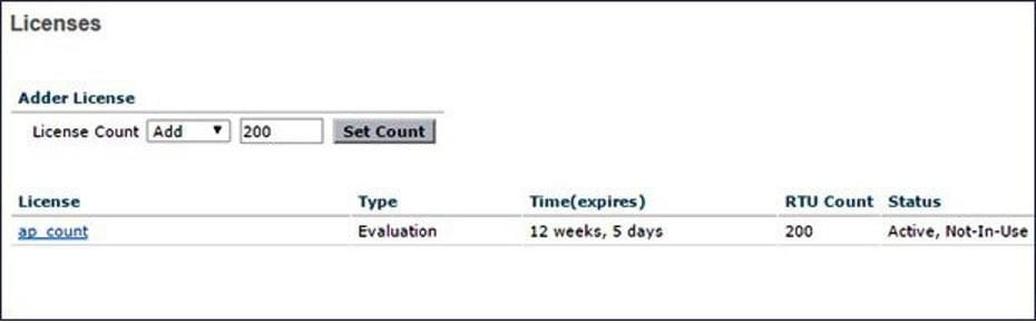
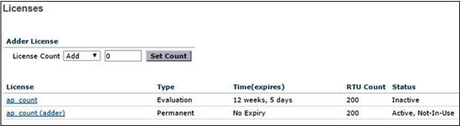
Step 1 To install AP adder licenses, click Management > Software Activation > Licenses. Step 2 In the Adder Licensearea, in the License Count field, set the license task to Add, enter the number of AP licenses you have purchased for the vWLC, and then click Set Count.
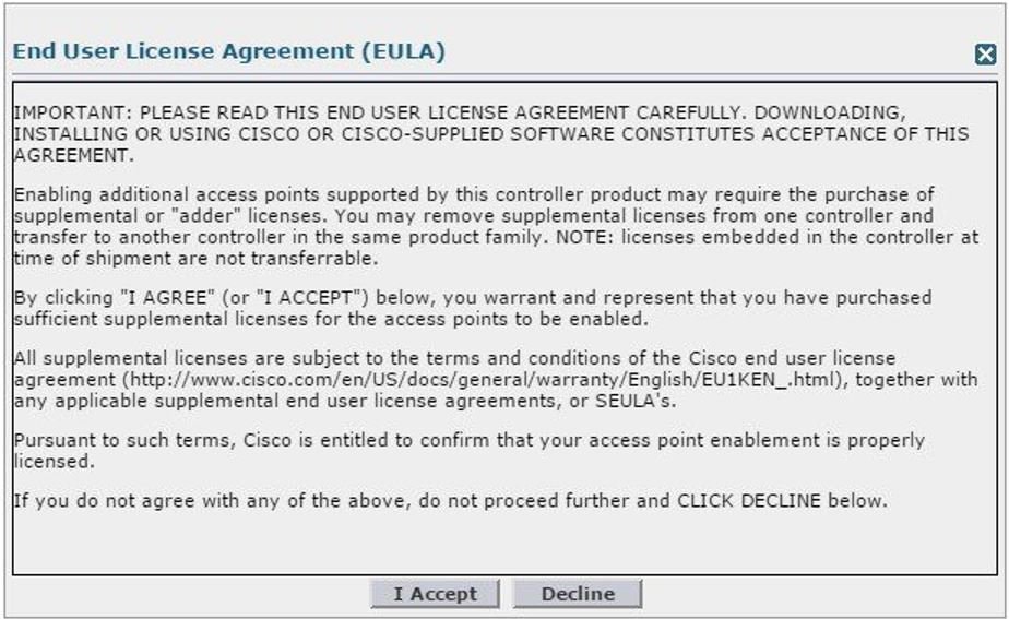
Step 3 Read the End User License Agreement (EULA) and click I Accept.
The AP adder licenses are installed and activated on the vWLC.
RTU Licensing Using CLI
Procedure
Step 1 To install AP adder licenses using the CLI, enter the following command: (Cisco Controller) > license add ap-count<1-200>
Step 2 Read the End User License Agreement(EULA), type Y, and press Enter to accept: Feature Name: ap-count
Right to Use

Enabling additional access points supported by this controller
product may require the purchase of supplemental or "adder"
licenses. You may remove supplemental licenses from one controller
and transfer to another controller in the same product family.
NOTE: licenses embedded in the controller at time of
shipment are not transferrable.
By clicking "I AGREE" (or "I ACCEPT") below, you warrant
and represent that you have purchased sufficient supplemental
licenses for the access points to be enabled.
All supplemental licenses are subject to the terms and
conditions of the Cisco end user license agreement
(http://www.cisco.com/en/US/docs/general/warranty/English/EU1KEN_.html),
together with any applicable supplemental end user license agreements,
or SEULA's.
Pursuant to such terms, Cisco is entitled to confirm that your
access point enablement is properly licensed.
If you do not agree with any of the above, do not proceed further
and CLICK "DECLINE" below. ACCEPT? [y/n]: Y
Successfully added the license.
Step 3 The AP adder licenses are installed and activated on the vWLC. You can view the installed licenses by typing the show license summary command: (Cisco Controller) > show license summary
Feature name:
ap_count License type:
Evaluation License Eula:
Not Accepted
Evaluation total period: 12
weeks 6 days License state:
Inactive, Not-In-Use
RTU License Count: 200

Feature name:
ap_count (adder)
License type:
Permanent
License state:
Active, Not-In-Use
RTU License Count:
200
Step 4 To activate or deactivate a feature license, enter the following command: license {activate | deactivate} feature license_name
Smart Licensing
Cisco Smart Software Licensing makes it easier to buy, deploy, track, and renew Cisco software by removing today’s entitlement barriers and providing information about your software install base. This is a major change to Cisco’s software strategy, moving away from a PAK-based model to a new approach that enables flexibility and advanced consumer-based models.
With Cisco Smart Software Licensing, you will have:
Visibility into devices and software that you have purchased and deployed
Automatic license activation
Product simplicity with standard software offers, licensing platform, and policies
Possibility of decreased operational costs
You, your chosen partners, and Cisco can view your hardware, software entitlements, and eventually services in the Cisco Smart Software Manager interface.
All Smart Software Licensed products, upon configuration and activation with a single token, will self-register, removing the need to go to a website and register product after product with PAKs. Instead of using PAKs or license files, Smart Software Licensing establishes a pool of software licenses or entitlements that can be used across your entire portfolio in a flexible and automated manner. Pooling is particularly helpful with RMAs because it eliminates the need to re-host licenses. You may self manage license deployment throughout your company easily and quickly in the Cisco Smart Software Manager.
Through standard product offers, a standard license platform, and flexible contracts you will have a simplified, more productive experience with Cisco software.
Smart Licensing Using Web GUI
The below steps are for the Direct Cloud Access, the most common deployment mode. This guide is not intended to explain or cover Smart Licensing in-depth. It is expected that the user already has access and fully understands Smart Licensing feature and administration.
The user must have the ability to create a token-ID required to register the vWLC. Please refer to the deployment guide for more information regarding Smart Licensing if needed.
Enable Smart Licensing and Register Device
Procedure
Step 1 To activate Smart Licensing on the WLC go to Management > Software Activation > License Type. Step 2 Select Licensing Type as Smart-Licensing from the drop-down menu. Enter the DNS server IP address that will be used to resolve the Smart License and Smart call-home URLs in the call-home profile. Click Apply.
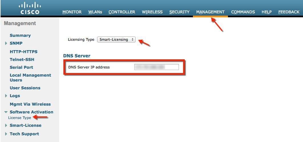
After this step, restart the controller under Commands > Restart.
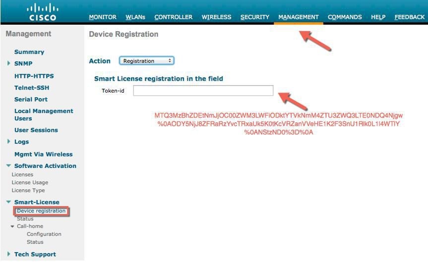
Step 3 Go to Management > Smart-License > Device registration. Select action as Registration. Register the device by entering the copied token ID.
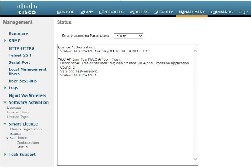
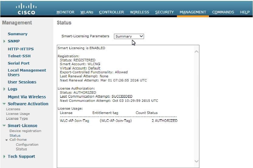
Step 4 Verify the status of Registration and Authorization under Management > Smart-License > Status.
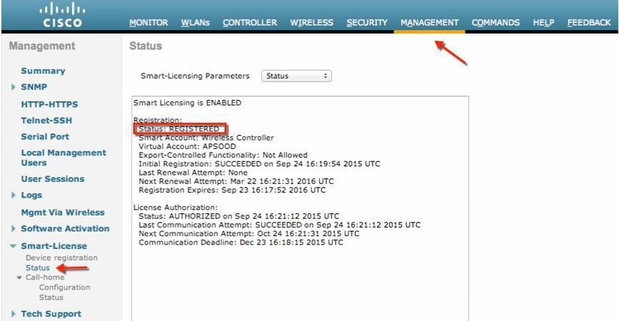
In the CSSM portal the device will show up under the Product Instances tab on the corresponding virtual account that the device was registered with.
Step 5 Once APs join the WLC, entitlements are requested once in 24 hours and the status of entitlements can be viewed under Management > Smart-license > Status.
Virtual Controller Management with Cisco Prime 3.0
ProcedureCisco Prime Infrastructure version 3.0 is the minimum release required to centrally manage one or more Cisco Virtual Controller(s). CPI 3.0 provides configuration, software management, monitoring, reporting and troubleshooting of virtual controllers. Refer to Cisco Prime Infrastructure documentation as required for administrative and management support.
Cisco Prime Compatibility Matrix:
Step 1 Log into Cisco Prime Infrastructure server as root.
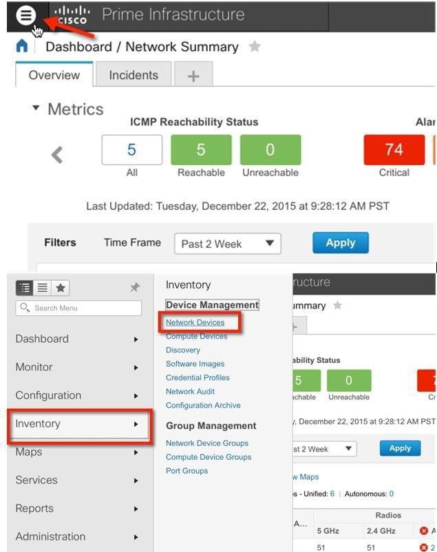
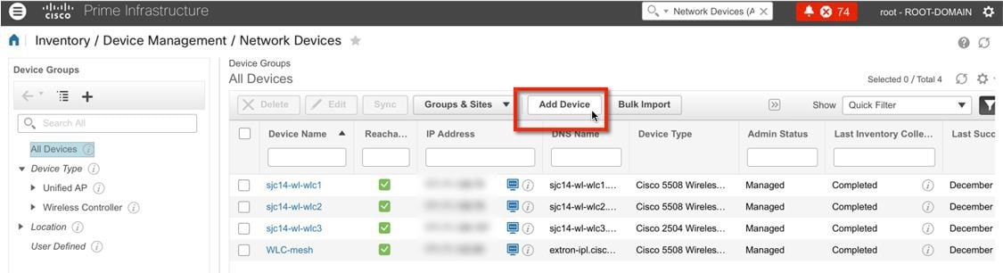
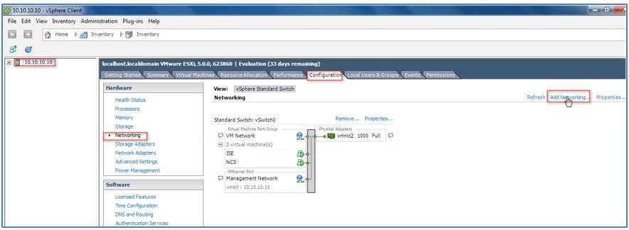
Step 2 Navigate to Inventory, and Device Management > Network Devices.
Step 3 In Network Devices, click Add Device.
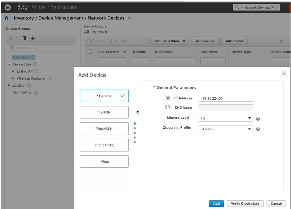
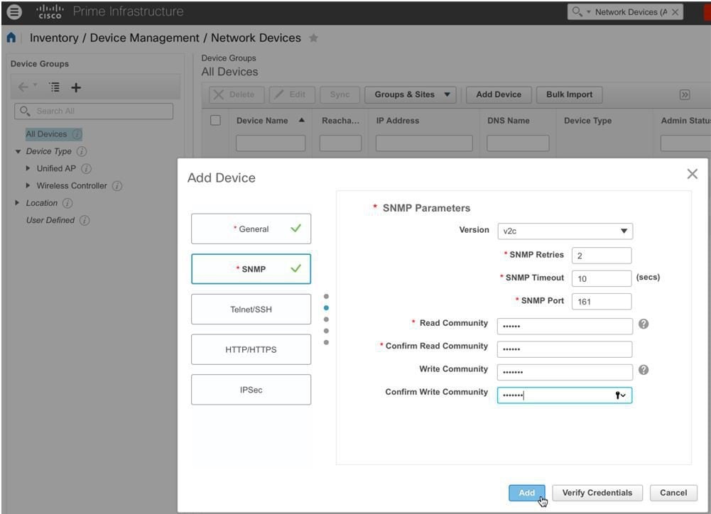
Step 4 Enter the IP address and SNMP community string (Read/Write). By default, the SNMP RW for the controller is Private, and click Add.
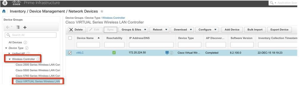
Step 5 Cisco Prime Infrastructure will discover and synchronize with the virtual controller, and click on the refresh button to update the screen. When the virtual controller is discovered, it will list as Managed, with good Reachability shown in green. Add any other virtual controller(s) at this point if available.
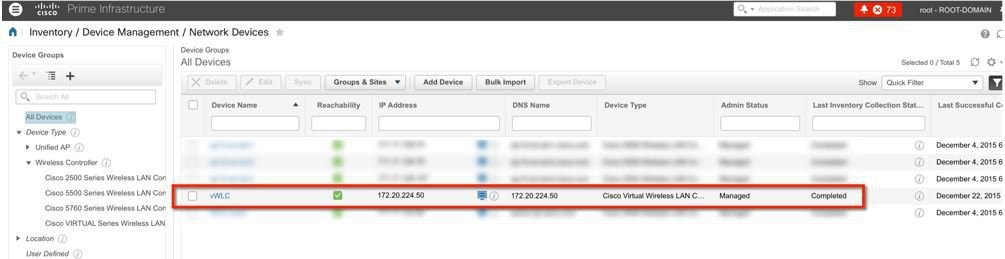
Step 6 The new controller will be listed in the Device Type, Cisco Virtual Series Wireless LAN Controller.
Upgrading the Virtual Controller
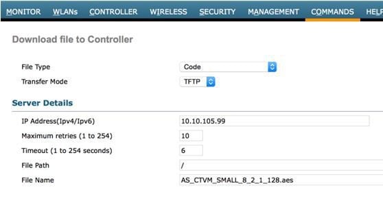
ProcedureIn the early steps of installation, the Cisco Virtual Controller initially required an OVA file for new virtual appliance creation; however, maintaining virtual controller features and software upgrade require a common AES file downloadable from Cisco site.
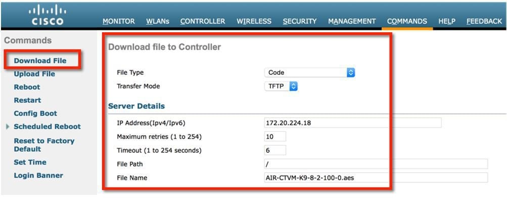
Step 1 Download the upgrade software *aes file to a target host (e.g. TFTP/FTP) or use HTTP file transfer. Step 2 Same as for legacy controllers, navigate to the web GUI of the controller, COMMANDS > Download File. Select File Type, Transfer Mode, IP address, path and File Name (aes file). Click Download button to start the process.
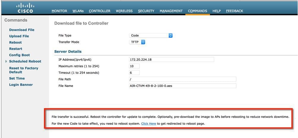
Step 3 When the process is completed successfully, user will be prompted to Reboot to take into effect of the new software image. Click on the link to the Reboot Page to continue.
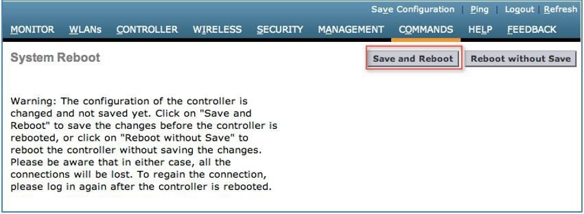
Step 4 Click Save and Reboot.
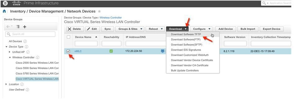
Step 5 Cisco Prime Infrastructure 3.0 can also be useful for upgrading virtual controller, or many virtual controllers at the same time. Navigate to Network Device. Select (check box) one or more virtual controller(s) > from the command pull-down select Download (TFTP/TFTP). This example uses TFTP mode of image upgrade.
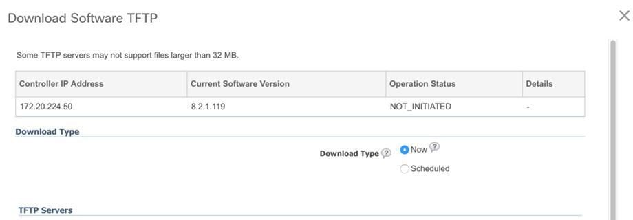
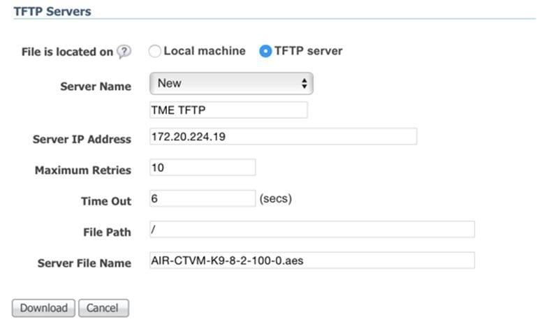
Step 6 Provide the Download Type (Now / Scheduled) > New or Existing server IP address, path and Server File Name (*.aes upgrade software). Click Download to begin.
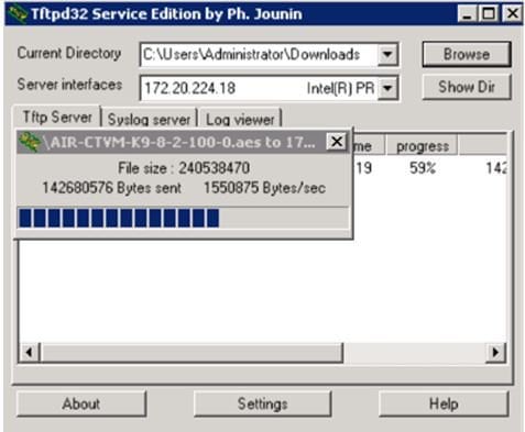
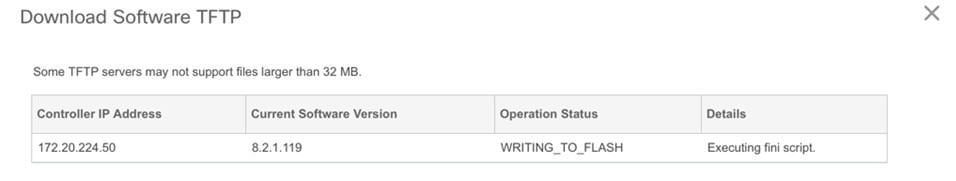
Step 7 The following screen is an example of the AES image being transferred to the virtual controllers from a TFTP server.
Step 8 Cisco Prime Infrastructure will update the status until the software has successfully been transferred.
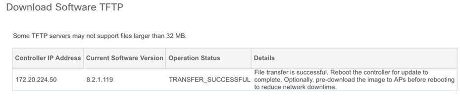
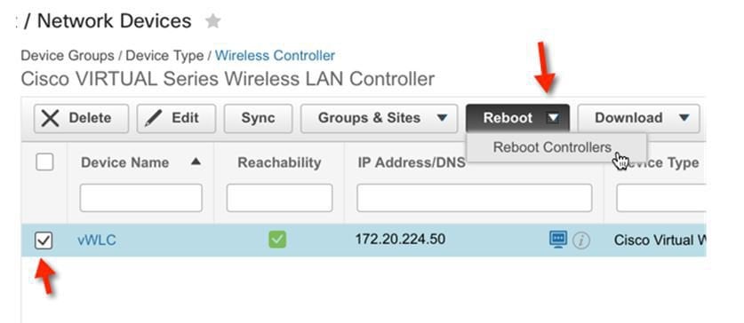
Step 9 Similar to the experience directly from the controller, when the transfer is complete a reboot is required. Navigate in Cisco Prime Infrastructure by selecting the virtual controller(s), and select from command pull-down, Reboot > Reboot Controllers.
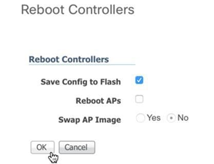
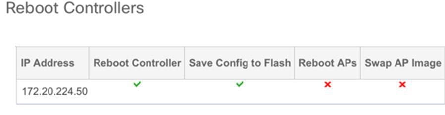
Step 10 Cisco Prime Infrastructure will prompt for reboot parameters such as save configuration, etc. Click OK to continue.
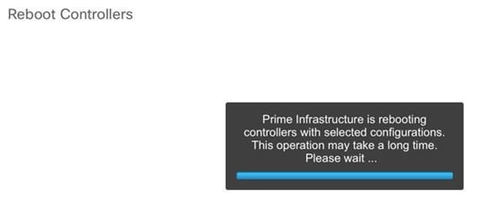
Step 11 Cisco Prime Infrastructure will notify the admin that the virtual controllers are being rebooted.
Step 12 When complete, Cisco Prime Infrastructure will provide the result of the process.
Copyright © 2015, Cisco Systems, Inc. All rights reserved.

 Feedback
Contact Cisco
- Open a Support Case

- (Requires a Cisco Service Contract)