CUWN 8.8 WLC and FC AP - EoGRE Tunnel Gateway Deployment Guide
WLC EoGRE Tunneling
Ethernet over GRE (EoGRE) is a new aggregation solution for aggregating Wi-Fi traffic from hotspots. This solution enables customer premises equipment (CPE) devices to bridge the Ethernet traffic coming from an end host, and encapsulate the traffic in Ethernet packets over an IP GRE tunnel. When the IP GRE tunnels are terminated on a service provider broadband network gateway, the end host’s traffic is terminated and subscriber sessions are initiated for the end host.
Benefits of Tunneling in General
-
Client can maintain IP address and policy across heterogeneous access networks with different technologies and/or vendors.
-
Bypass MAC address scaling limitation of the L2 switch connecting to the WLC.
-
Lawful Intercept (LI)
-
Reduces network congestion by reducing OpEx and increasing network efficiency by offloading 3G and 4G traffic.
-
Provides access to 3G and 4G core in spite of a lack of weak cell signal, leading to subscriber retention.
-
Lowers CapEx on per user basis or bandwidth basis in dense metro environments.
-
Provides WiFi security and subscriber control.
-
Delivers scalable, manageable, and secure wireless connectivity.
-
Enables new revenue-sharing business models.
-
Delivers a WiFi platform that offers new location-based services.
-
Provides enhanced quality of experience to subscribers on WiFi networks.
-
Provides unified billing across access networks.
-
Provides mobility across radio access technologies—3G or 4G to WiFi and WiFi to WiFi.
-
Provides multiple options within the Wi-Fi platform, thereby enabling location-based services.
-
Begin with rel 8.2 EoGRE Tunneling is supported on the Dynamic interface.
-
Dynamic IPv6 AP-manager interface is not supported.
-
In rel 8.3 Dynamic interface with IPv6 supports only as tunnel interface.
-
In rel 8.3 maximum number of dynamic interface to which IPv6 address can be assigned is 16.
-
In rel 8.3 TGW supports both IPv4 and IPv6 address format. You can create up to 10 tunnel gateways.
-
In release 8.4 EoGRE IPv4 and IPv6 tunnel is supported from WLC and Flex Connect AP to TGW.
-
In release 8.5 support for Primary and Secondary TGW failover and redundancy was added.
-
In release 8.5 SNMP MIBs are added to manage the EoGRE tunnel.
-
In release 8.6 added support for the DHCP Option 82 on the Cisco Wave-2 APs
-
In release 8.6 added enhancement to send keep-alive to the TGW mapped to the enabled WLANs
-
In Release 8.8 VLAN override enhancement was added to eliminate 10 VLAN support and increase it to number of the VLANs supported by a specific controller model, i.e. 5520 and 8540 support up to 4096 VLANs
Supported Controller and APs
-
Cisco 3504, 5508, 5520 series, and vWLC wireless controllers
-
Rel 8.2 – 8.5 support EoGRE on the 2500 series
-
7500 controllers support only Flex Connect Aps with EoGRE direct tunnel to TGW.
-
Cisco WLC 8.8 supported access points—3700, 2700, 1700, 702, 702W, 1530, 1570
-
Wave-2 APs: 1800 series, 2800 series, 3800 series, 4800 series; 1540 and 1560
In rel 8.8 and starting with rel 8.5 Cisco 3504, 5520, 8540 and vWLC are supported.
 Note |
Please reference to the 8.8 release notes for the list of the supported APs. |
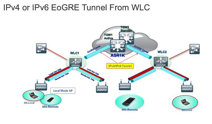
EoGRE Tunnels System Design Options
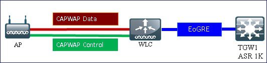
Design 1: WLC based EoGRE Tunnel
-
CAPWAP Control Path (AP-WLC)
-
CAPWAP Data Path (AP-WLC)
-
EoGRE Data Flow (WLC-TGW)
-
IP/GRE as defined in PMIPv6 (RFC 5213) – L3
-
Ethernet over GRE – L2
Note |
In this deployment guide, only EoGRE tunnel is discussed. |
Only one type of tunnel is supported per WLAN. EoGRE is supported on either open or 802.1x based WLANs. Tunneled clients support EAP-SIM or EAP-AKA mode only. Other authentication modes are not supported by the tunneled clients.
When open SSID WLAN is used, either all local/simple or all tunneled clients are supported but cannot be mixed on the same WLAN. However, 802.1x authenticated simple or tunneled EoGRE clients are supported on the same WLAN.
Prior to Release 8.3, only WLANs configured for Open and WPA2-802.1X were supported.
It is now possible to assign EoGRE Tunnel Profiles to WLANs configured for Internal WebAuth and WPA2-PSK. WLANs configured with WPA2-PSK / WPA2-802.1X and Internal WebAuth are also supported.
Based on authentication, clients will be separated into local or tunneled mode. The WLC supports two types of user’s traffic such as Remote-Tunneled and Local on the same WLAN.
Local users traffic is defined as traffic that is locally bridged by the WLC.
Remote-Tunneled user traffic is defined as traffic of remote-tunnel users and is tunneled by the WLC to a TGW.
AAA override for EoGRE users is supported. Tunnel gateway can also act as AAA proxy.
-
WLC parses Access Accept and looks for MPC-Protocol-Type, such as EoGRE, GTPv2 or PMIPv6.
-
If the Protocol-Type AVP exists, WLC looks for all parameters related to that tunnel-type. The static profile is ignored and the AAA provided parameters are used to setup tunnel.
-
If AVP is not present, WLC uses static profile on WLC to determine tunnel type based on the realm extracted from user name.
-
If some of the parameters are not present, the authentication fails. For example, if everything is present except T-GW IP, then the client authentication fails.
-
If the MPC-Protocol-Type is None, then it will be simple IP.
Some of the attributes that can be returned by the AAA server are: User-Name, Calling-Station-Id, gw-domain-name, mn-service, cisco-mpc-protocol-interface, and eogre_vlan_id.
Configuring WLC EoGRE Tunneling
To configue EoGRE tunnel, perform the following steps:
Procedure
| Step 1 |
To configure EoGRE feature, create SSID. |
||
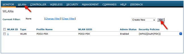
| Step 2 |
From the WLC main menu, choose WLANs and click Go.
|
||
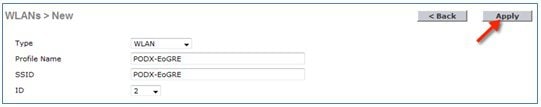
| Step 3 |
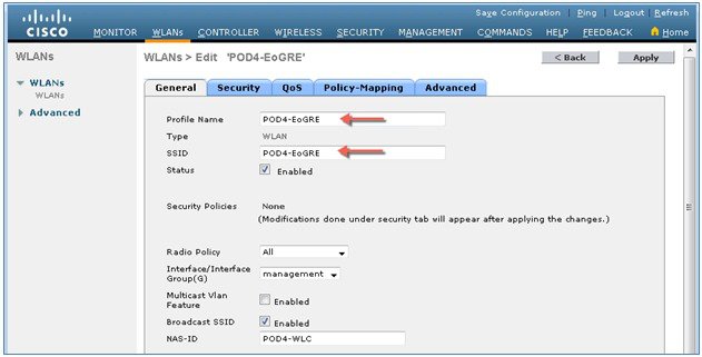
Create a WLAN with the naming convention, for example, POD4-EoGRE, and then click Apply.
|
||
| Step 4 |
On the General tab, map the WLAN to management interface or begin with rel 8.2 choose a Management or a Dynamic Interface.
|
||
| Step 5 |
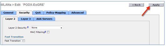
On the Security tab, set Layer 2 Security to None, and then click Apply.
|
Configuring WLC EoGRE tunnel parameters
Note |
EoGRE tunnel configuration can be performed through GUI or CLI. |
Support for IPv6 addresses on the TGW in rel 8.3
In Release 8.3, support is added for client IPv6 traffic and IPv6 address format for the EoGRE tunnel gateway. Client IPv6 traffic is supported on both IPv4 and IPv6 EoGRE tunnels. A maximum of 8 different client IPv6 address supported per client. Cisco WLCs send all the client IPv6 addresses that they have learned to the Accounting server in the accounting update message. All RADIUS or Accounting messages exchanged between Cisco WLCs and tunnel gateways or RADIUS servers are outside the EoGRE tunnel.
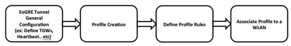
To configure the WLC EoGRE tunnel through GUI, perform the following steps:
Procedure
| Step 1 |
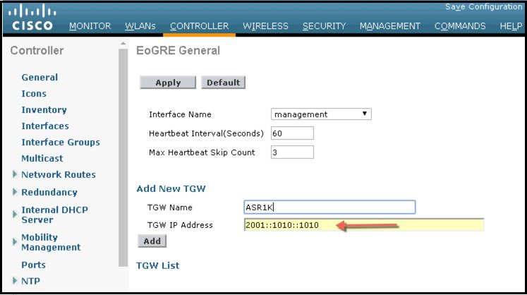
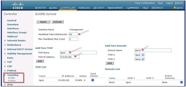
Assign a tunnel gateway address:
|
||
| Step 2 |
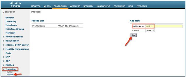
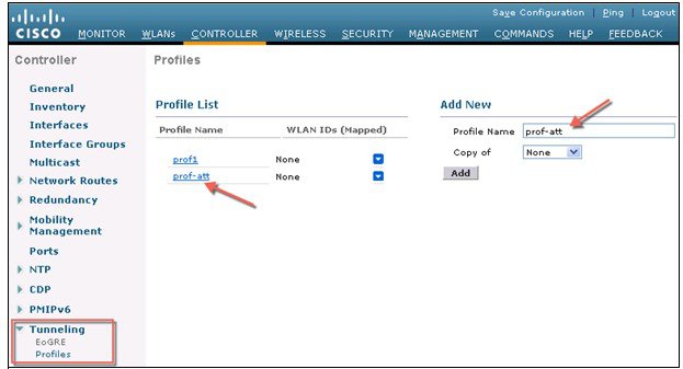
Create a tunnel profile:
|
||
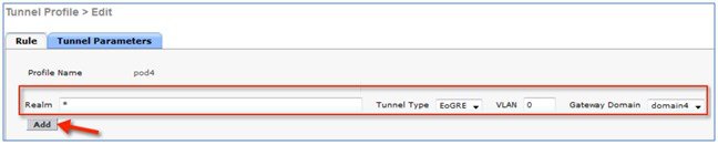
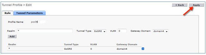
| Step 3 |
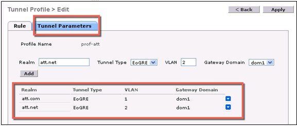
Define a tunnel profile rule:
|
||
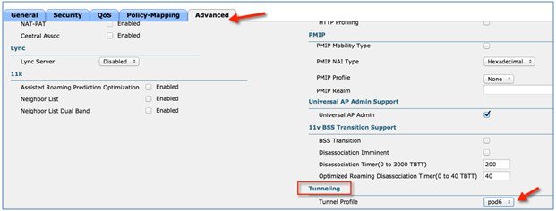
| Step 4 |
Add / Associate the tunnel profile to WLAN:
|
||
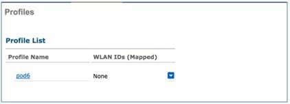
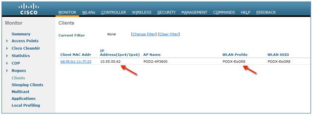
| Step 5 |
To verify if the tunnel is properly configured, from WLC main menu, choose CONTROLLER > Tunneling > Profiles and see if the profile name is set to the correct WLAN. In this example, the ASR1K is pre-configured for EoGRE tunnel and a DHCP pool. For your reference, the tunnel configuration on ASR1K is shown below. 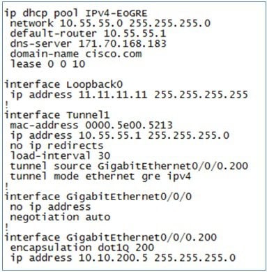
Connect a wireless client to the SSID, for example, POD4-EoGRE. You get an IP address from 10.55.55.0 subnet, which is configured on the ASR1K. 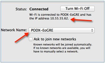
You can also verify that the client is associated through EoGRE tunnel by running show client detail command on your POD WLC. 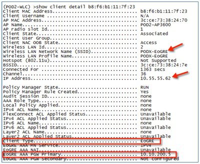
|
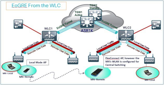
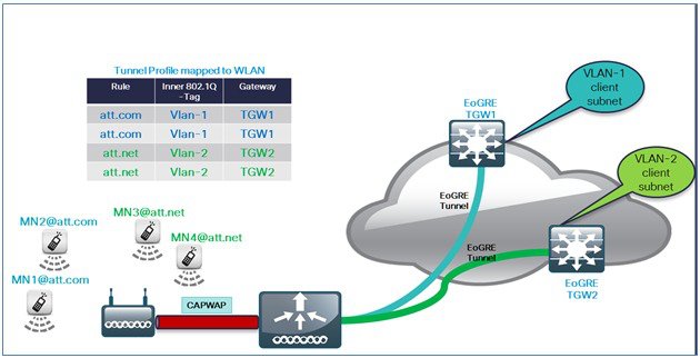
Typical Deployment: WLC EoGRE Topology
In this typical EoGRE deployment configuration, two users MN1 and MN2 are connected to Realm @att.com and two other users MN3 and MN4 are connected to Realm @att.net. When the users MN1 and MN2 connect, they must be on the VLAN1 and TGW1 and users MN3 and MN4 must connect to VLAN2 and TGW2 as shown in the following figure. In this setup, two profiles with one realm in each are created and mapped to TGW1 and TGW2 accordingly in the same domain.
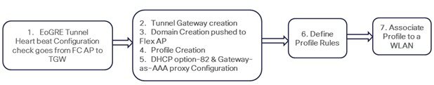
To configure WLC EoGRE, perform the following steps:
Procedure
| Step 1 |
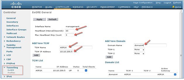
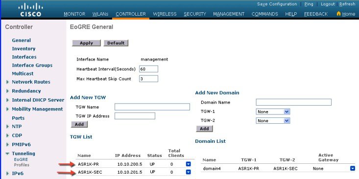
Create tunnel gateways and configure heartbeats:
|
||
| Step 2 |
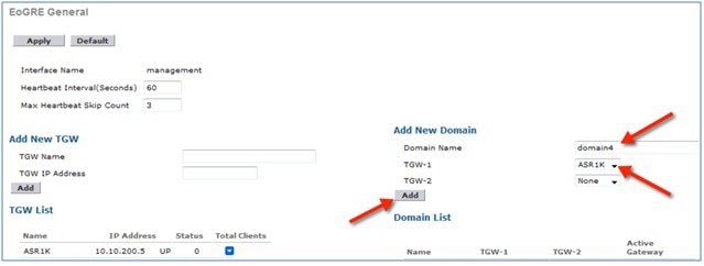
Configure EoGRE Tunnel Domain. 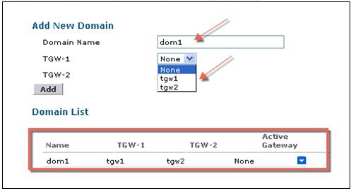 To create tunnel domain from CLI:
|
||
| Step 3 |
Create profiles and add rules:
|
||
| Step 4 |
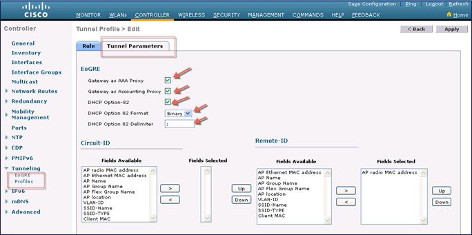
Configure the tunnel parameters. The following figure shows a sample configuration from GUI of tunnel parameters with AAA proxy GW enabled and and DHCP option-82 enabled. 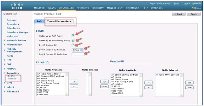
|
||
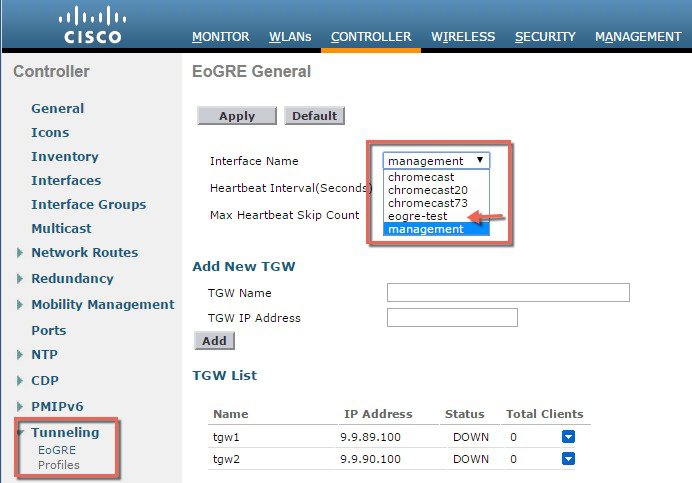
| Step 5 |
Configuring EoGRE Tunnel from GUI On the controller general interface when configuring Interface
name choose other than Management interface.
 |
||
| Step 6 |
Map the profile to a WLAN. 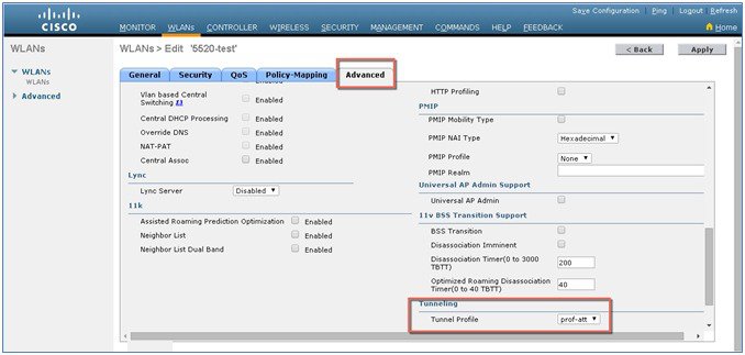 To map the profile to WLAN2 from CLI:
|
Tunneling Source Changes in Release 8.2
Prior to releases 8.2, for all Tunnels, e.g. EoGRE, PMIPV6 etc., only management interface could be used as the tunnel end point. In release 8.2 a capability was added to specify a tunnel source other than management interfaces so that data traffic and management traffic in the network can be segregated in different network segments.
-
There are 4094 L3 interfaces available for configuration.
-
Admin is able to configure the dynamic interface as the tunnel endpoint for tunnels like EoGRE
-
There are no changes in the configuration for any features with the exception of tunneling protocols mentioned above.
-
IPv6 addresses on dynamic interface are not be supported in 8.2.
-
AP Manager cannot be enabled on the L3 interface, which is hosting a tunnel (EoGRE, PMIPv6 and so on).
-
All Controllers including vWLC and 2500 are supported.
In Release 8.2, all 4094 interfaces are L3 dynamic interfaces (if IPv4 is configured as IPv6 then it is not supported on these interfaces in 8.2) for all types of supported controllers except vWLC, for which only 512 L3 interfaces will be supported. If IP address is not configured, they remain as L2 interface. These L2 interfaces are not used as client interfaces in this release to avoid change in the behavior of the controller already deployed in the field, upgrade or downgrade scenario, and DHCP Support (Supporting DHCP using the L2 parameter instead of L3 parameter in Option 82 to get the IP on that L2 interface). Based on the requirements these L2 interfaces may be used as client interfaces in subsequent releases.
The dynamic interface feature is specific to tunnel from the WLC to WAG. For tunnels from the AP the tunnel source will always be the interface having the AP IP assigned to it. The tunnel Outer VLAN will be the VLAN of this AP interface on which the IP is assigned.
EoGRE Tunnel DHCP Option-82 Design
The DHCP option-82 for EoGRE clients is inserted at the WLC in the bridge mode. The DHCP request packets from the clients are punted up to the controller as with any other DHCP packets. In the controller, based on the client type, the EoGRE clients are handled specially. For EoGRE clients, the DHCP option-82 configurations are picked from the Tunnel Profile data base. The global DHCP configurations have no impact on EoGRE clients.
The DHCP code in controller inserts DHCP option-82 parameters based on the tunnel profile configurations. Also, the EoGRE tunnel header information is added in the controller. The controller assembles the complete DHCP packet along with EoGRE tunnel headers and sends out on the tunnel.
The configuration commands give flexibility to configuring option-82format , delimiter character, remote-id, and circuit-id. The remote-id and circuit-id can be easily configured by providing up to a maximum of five different parameter-ids supported. The parameters entered will overwrite the previously entered configurations. If no parameters are input, the remote-id and circuit-id will be erased and no parameter for that field will be sent.
Begin with release 8.6 DHCP Option 82 for EoGRE Tunnel is supported in Cisco Wave 2 APs.
Configuration commands
config tunnel profile eogre
                     		  <profile name> dhCP-Opt-82 enable / disable
config tunnel profile eogre
                     		  <profile name> dhCP-Opt-82 format binary / ascii
config tunnel profile eogre
                     		  <profile name> dhCP-Opt-82 delimiter <delimiter character>
config tunnel profile eogre
                     		  <profile name> dhCP-Opt-82 remote-id <Paramater ID - 1>
                     		  <Paramater ID - 2> <Paramater ID - 3> <Paramater ID - 4>
                     		  <Paramater ID - 5>
config tunnel profile eogre
                     		  <profile name> dhCP-Opt-82 circuit-id <Paramater ID - 1>
                     		  <Paramater ID - 2> <Paramater ID - 3> <Paramater ID - 4>
                     		  <Paramater ID - 5>
To configure DHCP option82 from CLI:
config tunnel profile eogre
                     		  prof-att DHCP-Opt-82 format Binary
config tunnel profile eogre
                     		  prof-att DHCP-Opt-82 delimiter
config tunnel profile eogre
                     		  prof-att DHCP-Opt-82 enable
config tunnel profile eogre
                     		  prof-att DHCP-Opt-82 circuit-id ap-ethmac flex-group-name
                     		  ap-group-name
config tunnel profile eogre
                     		  prof1 DHCP-Opt-82 remote-id ap-name ap-location
To configure gateway as AAA proxy from CLI:
config tunnel profile eogre
                     		  prof-att gateway-radius-proxy enable
config tunnel profile eogre
                     		  prof-att gateway-radius-proxy accounting enable
Redundancy of the EoGRE Tunnels
Two or more tunnels can be configured for redundancy, so that when the primaryor active tunnelfails, the secondaryor standby tunnel will take over the operation of the EoGRE tunnel.Keep-alive messages are sent periodically and the periodicity is configurable, that is, how many keep-alives can be missedbefore tunnel is considered as down. This is a global commandand is applicable for all types of tunnels. In EoGRE tunnelsdesign, DTLS ICMP packets are sent to the tunnelgateway. When EoGRE tunnelis created, ICMP echo request packetis sent to the tunnel gateway. After receiving, ICMP echo responseis sent back updating the tunnel gateway status.
When primary tunnel fails, the clients will de-authenticate and dis-associate from the primary WAG. If a secondary WAG is available, the controller will establish a secondary tunnel and reconnect to the secondary WAG, if the secondary tunnel is configured as shown in the following example. After secondary tunnel is established, the remote-client devices will re-authenticate and re-associate to WAG and will renew their IP addresses from the DHCP server on the secondary WAG. Clients will remain connected to the secondary WAG even if the primary WAG comes back on line.
Redundancy and Failover in rel 8.5
Prior to release 8.5 EoGRE TGW failover was not controlled as primary or secondary for the failover or redundancy as indicated in the screen shot above. In release 8.5 a new option available for the TGW-1 and TGW-2 as Primary and Secondary for the failover purposes.
In a Domain, Primary gateway is active by default, when Primary gateway goes down then secondary gateway becomes active or Primary. Clients will have to re-associate to secondary gateway. During and after failover the WLC continues to ping the primary gateway, when primary gateway comes back on line then the primary gateway becomes Active gateway. Clients will fallback to primary gateway.
With the rel of 8.6 additional enhancements added to reduce keep-alive ping overhead.
Prior to Release 8.6 WLC was sending ”keep-alive” to all TGWs configured on WLC.
In release 8.6 “keep-alive” sent only to TGWs which are mapped to the enabled WLANs.
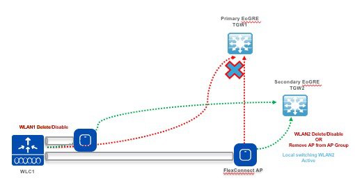
When WLAN disabled or deleted on WLC, periodic “keep-alive” will stop to the TGW to which WLAN were mapped.
When WLAN disabled/deleted on WLC then delete message of those gateways sent to AP and AP group.
Same option is available for the TGW from the Flex Connected Aps in a locally switched mode.
Note |
AP 1040, 1260 and 1140 are not supported starting rel 8.5. |
Configurations Steps for EoGRE TGW Failover
Procedure
| Step 1 |
Configuring EoGRE Tunnel from CLI or GUI with IPv4 or IPv6 addresses. 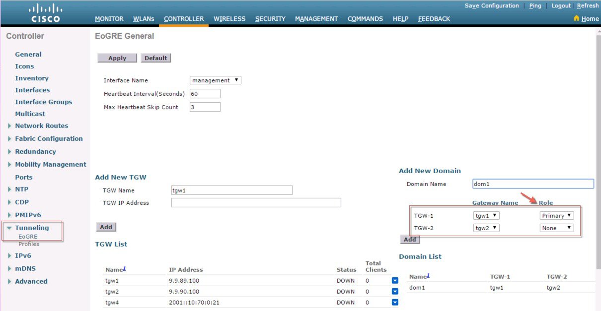 |
| Step 2 |
Configuring EoGRE Profile with VLAN and Domain from CLI or GUI . 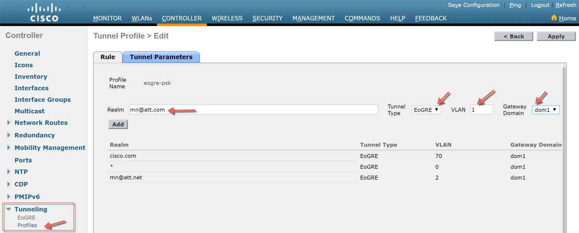 |
| Step 3 |
Configure WLAN with Flex Connect Local Switching. 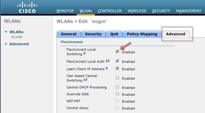 |
| Step 4 |
Configure WLAN and bind EoGRE Tunnel Profile. 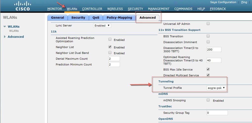 |
| Step 5 |
Bind profile to WLAN as shown below. 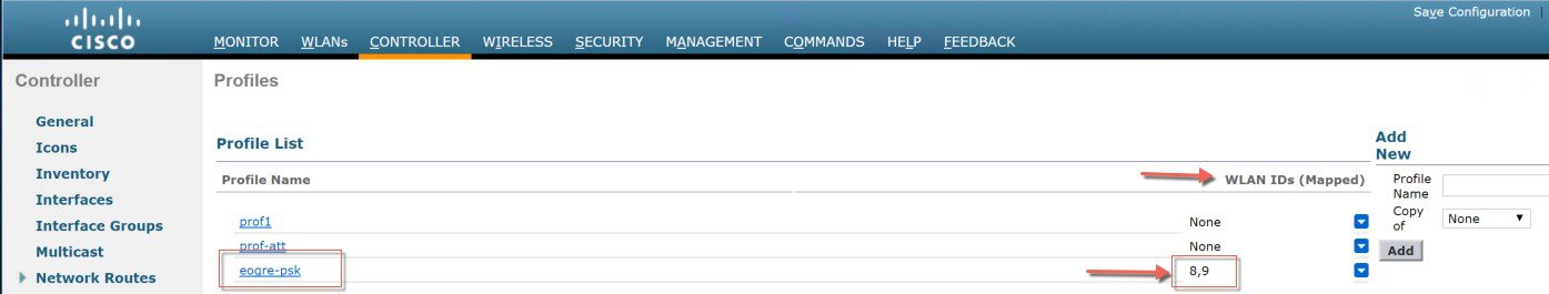 |
EoGRE Tunnels with VLAN Override Feature in rel 8.8
Some of the Cisco customers that deploy EoGRE tunnelling have an issue with supported number of VLANs. The problem they are facing is that our EoGRE implementation for open SSIDs is limited to a maximum of 16 SSIDs/VLANs per WLC. They provide those open SSIDs to their B2B customers (hotels, food chains, cafes, etc...)
That’s a huge limitation for a Service Provider application, especially if you take into account that 5520 or 8540 controllers supports 512 WLANs/4096 VLANs.
The limitation happens because for open SSIDs we are forced to use wildcards to identify them and map to VLANs. That leads to only one SSID/VLAN pair per tunnel profile and then a maximum of 10 SSID/VLAN pairs per box (because there is a maximum limit of 10 tunnel profiles).
Certain Cisco cusstomers need to have a one to one mapping between open SSIDs and VLANs because VLAN on the WiFi GW identifies the B2B customer and the policies are applied.
To solve the above-mentioned Service Provider’s issue a new enhancement was introduced in the release 8.8. This enhancement will introduce one-to-one Mapping of WLAN to EoGRE VLAN. Prior to release 8.8 512 WLANs are supported and only 10 EoGRE Profiles.
With this enhancement up to 4096 EoGRE VLAN’s from the Controller to the TGW will be supported.
In case of Open Auth Clients there will be only one “ * “ Rule which will have the EoGRE VLAN and other configuration for that WLAN.
With this new enhancement the EoGRE VLAN configuration will be overridden within the WLAN. All the existing Rules will apply. But when this EoGRE VLAN override option is enabled then this will override the EoGRE VLAN irrespective of AAA Override or Profile Rule match.
This will be the precedence order and nothing will be changed as part of this feature, AAA Override will be at the highest precedence.
-
If WLAN EoGRE VLAN override value
-
If AAA Override then AAA Values
-
NAI matched in the Profile Rule
Configuring WLC EoGRE Tunneling with VLAN Override
To configure EoGRE tunnel, perform the following steps:
Procedure
| Step 1 |
To configure EoGRE feature, create SSID. Create a WLAN with the naming convention, for example, “eogre-test”, and then click Apply. 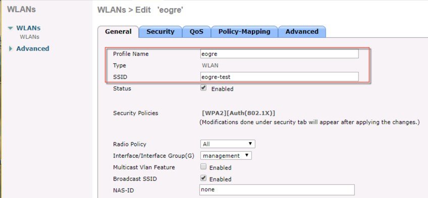 |
| Step 2 |
Assign a tunnel gateway address:
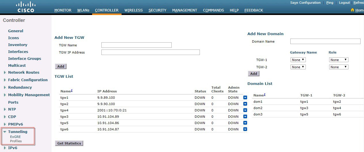 |
| Step 3 |
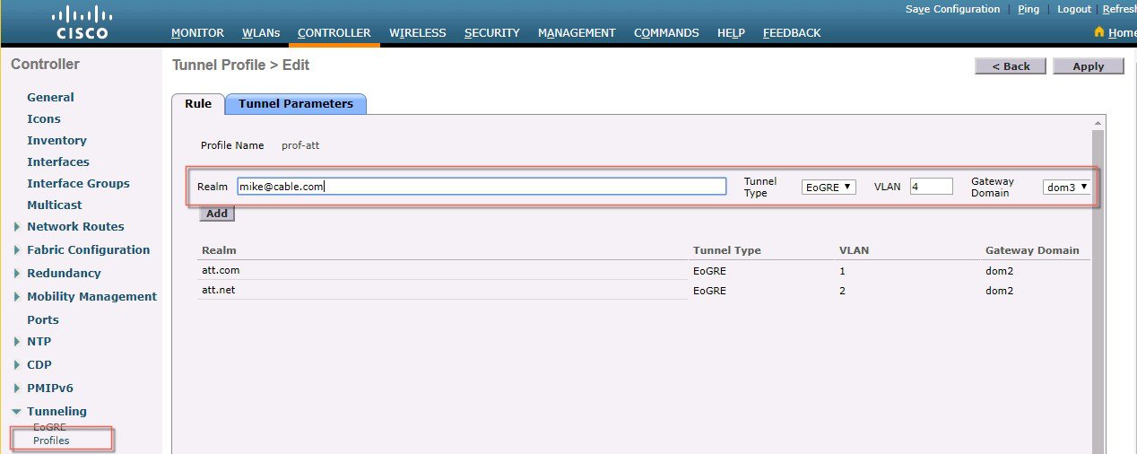
Define a tunnel profile rule:
 |
| Step 4 |
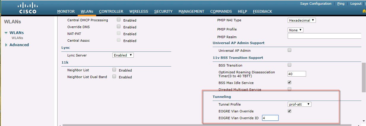
Add / Associate the tunnel profile to WLAN:
 |
CLI Commands for EoGRE VLAN Overridencept
Add following CLIs to enable feature and update override vlan.
# configure wlan tunnel profile eogre-vlan-override enable/disable-
Enables/Disables the EoGRE VLAN Override feature per WLAN.
-
LAN should be in disabled state to configure this.
# configure wlan tunnel profile eogre-vlan-override <vlanId> -
Configures VLAN ID in a WLAN.
-
This VLAN ID will be overridden with EoGRE VLAN ID configured in the tunnel profile.
-
WLAN should be in disabled state to configure this.
Default value is disable.
Default value of eogre vlan override is 0.
Console Log Example
(WLC-5520MA) >show wlan 3
DHCP Address Assignment Required................. Disabled
Static IP client tunneling....................... Disabled
Tunnel Profile................................... Prof1
EoGRE Override VLAN state........................ Enable
EoGRE Override VLAN ID........................... 4
PMIPv6 Mobility Type............................. none
    PMIPv6 MAG Profile........................... Unconfigured
    PMIPv6 Default Realm......................... Unconfigured
    PMIPv6 NAI Type.............................. Hexadecimal
    PMIPv6 MAG location.......................... APQuality of Service.................... Gold
Per-SSID Rate Limits............................. Upstream     Downstream
Average Data Rate....................................   0             0
Average Realtime Data Rate.....................   0             0
Burst Data Rate.........................................   0             0
Burst Realtime Data Rate..........................   0             0
Per-Client Rate Limits........................... Upstream      Downstream
Average Data Rate.....................................   0             0
Average Realtime Data Rate......................   0             0
Burst Data Rate..........................................   0             0
Burst Realtime Data Rate..........................   0             0
Scan Defer Priority.............................. 4,5,6
Scan Defer Time.................................. 100 milliseconds
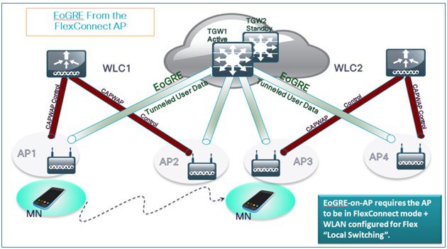
Design 2: FlexConnect AP based EoGRE Tunnel
-
CAPWAP Control Path (Flex AP-WLC)
-
EoGRE Data Path (Flex AP-TGW)
-
Once tunnel is established, data flows from FC AP directly to the TGW.
In this design, direct tunneling from the AP offers data and control planes separation from the controller and the AP. The central data throughput is limited only by the capacity of the core network with optimal data-path routing towards the core of the network. The inter/intra controller mobility is not supported but client can still roam in the same FlexConnect group in Locally Switched mode.
-
FlexConnect AP – EoGRE is supported on Open and 802.1x based WLANs.
-
802.1x authenticated “simple” and “tunneled” EoGRE clients are supported on the same WLAN.
-
Based on authentication, clients are separated into local or tunneled mode.
-
Tunneled clients support EAP-SIM or EAP-AKA modes.
-
Open SSID WLAN supports either all local or all tunneled clients.
-
AAA override for EoGRE users is supported.
-
Tunnel GW can also act as AAA proxy.
-
Flex Connect AP supports TGW failure detection and switch over to alternate TGW.
-
TGW supports Fault Tolerance with Active/Standby mode.
-
Inter and Intra Controller mobility is supported in connected FlexAP mode.
-
In Stand-Alone mode, mobility supported only within FlexConnect group tunnel GW can be configured as AAA and Accounting proxy.
-
Tunnel GW supports “Configurable” DHCP Option-82.
-
Flex Connect supports IPv6 addresses in releases 8.4 and above.
Basic Flex AP EoGRE Configuration
When configuring Flex AP with EoGRE tunnel:
-
Same tunnel configurations apply to WLC or FC AP tunnels when profile is applied on the WLAN.
-
When FC AP is in Locally Switched mode, the FC AP gateway tunnel automatically applies.
-
Clients connected to Local Mode AP communicates through the WLC-TGW tunnel.
-
Clients connected to FC AP communicates through the FC AP-TGW tunnel.
-
Client selection is also impacted by the AAA or Profile override.
Note |
In redundancy tunnel configuration mode, the keep-alive pings will be sent from every FC AP that is configured in the EoGRE tunnel mode. |
Typical Deployment: Flex Connect AP - EoGRE Topology
In this typical FC AP -EoGRE tunnel deployment configuration, two users MN1 and MN2 are connected to Realm @att.com and two other users MN3 and MN4 are connected to Realm @att.net. When users MN1 and MN2 connect, they should be on the VLAN1 and TGW1 and users MN3 and MN4 should connect to VLAN-2 and TGW2 as shown in the following figure. In this setup, two profiles with one realm in each will be created and mapped to TGW1 and TGW2 accordingly in the same domain. In this deployment scenario, the tunnel will be setup directly between FlexConnect AP in a Locally switched mode and TGW1 and TGW2; all data traffic will flow bypassing the controller.
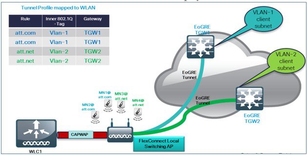
Note |
In this configuration, EoGRE tunnel TGW, Domain, Profile Rules, and Realms are setup exactly in the same manner as in the deployment scenario with WLC-EoGRE. The only change is FC AP is setup in the Locally Switched mode. |
-
Configure AP to FlexConnect Local Switching.
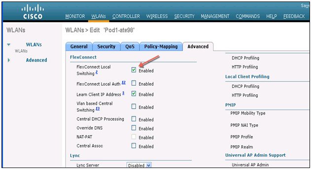
Note |
Only FlexConnect Local Switching option has to be configured on the FG AP or FC Group to enable FC AP-TGW tunnel. Other WLC EoGRE configurations will apply to FC AP-EoGRE settings. |
Managing EoGRE Feature
Begin with Release 8.5 the following SNMP MIBS are available to manage EoGRE Tunnel
-
* Gateway/ AP EoGRE Tunnel Admin State
-
* Gateway / AP EoGRE Tunnel Keepalive Loss
-
* Gateway / AP EoGRE Tunnel Uptime
-
* Gateway / AP EoGRE Tunnel traffic
-
* Controller / Gateway EoGRE Tunnel Admin State
-
* Controller / Gateway EoGRE Tunnel Keepalive Loss
-
* Controller / Gateway EoGRE Tunnel Uptime
-
* Controller / Gateway EoGRE Tunnel traffic
Troubleshooting commands
Existing interface/application related debugs will be reused. Below are the debugs and show commands to be used for packet flow, tunnel and IPv6 related issues.
Debugs:
debug arp all/detail/error/message enable/disable
debug packet logging enable all
debug pm rules enable/disable
debug ipv6 neighbor-binding
debug ipv6 address-learning
debug system printk
debug Tunnel eogre
debug Tunnel errors/events
Show commands:
debug fastpath dump vlandb
debug fastpath dump portdb
show system route
show arp kernel
Troubleshooting on the WLC:
- show tunnel eogre gateway summary.
- Debug tunnel eogre events/detail/errors enable.
- Show tunnel eogre statistics.
- Show ap eogre gateway <ap-name> - - - – shows tunnel information if tunnel is between AP and TGW.
Troubleshooting on FC AP:
show tunnel eogre gateway summary.
show dot11 eogre-tunnel gateway.
debug dot11 eogre-tunnel event/packets.
Feature Configuration Step-by-Step
There is no new CLI requirement for supporting L3 interface as such. In releases prior to 8.2, user cannot select any configured interface as tunnel end point other than management. New CLI, for configuring the global interface to be used as tunnel end point, will be required. This configuration will be separate for different types of tunnels e.g. EoGRE, PMIPv6 and so on.
For details on configuring PMIPv6 tunnels please refer to the following Deployment Guide http://www.cisco.com/c/en/us/support/docs/wireless/5500-series-wireless-controllers/113686-pmipv6-config-00.html
Configuring EoGRE Tunnel from CLI
config tunnel eogre interface <interface-name>Show Command:
show tunnel eogre summaryConfiguring PMIPv6 Tunnel from CLI
config pmipv6 interface <interface-name>show pmipv6 mag globalsShow Commands
Show Commands on WLC
Show tunnel eogre summary
show tunnel eogre gateway summary
show tunnel eogre domain summary
show tunnel profile summary
show tunnel profile detail <profile name>
show ap eogre domain <ap-name>
Show ap eogre gateway <ap-name>
Show Commands on AP
show dot11 eogre-tunnel domain summary
show dot11 eogre-tunnel gateway summary
show capwap reap associations
show capwap client detailrcb
Example Configuration of the EoGRE Feature
CLI Summary Steps on ASR 1K
-
enable
-
configure terminal
-
interface interface-name
-
ip unnumbered loopback interface-name or ip address ip-address
-
tunnel source interface-type interface-number
-
(For simple IP mode) mac-address H.H.H
-
tunnel mode ethernet gre ipv4 or tunnel mode ethernet gre ipv6
-
(Optional) tunnel vlan vlan-id
-
end
Sample Configuration on ASR 1K
aaa new-model
!
aaa group server radius AAA_SERVER_CAR
server-private 5.3.1.76 auth-port 2145 acct-port 2146 key cisco
!
aaa authentication login default none
aaa authentication login ISG_PROXY_LIST group AAA_SERVER_CAR
aaa authorization network ISG_PROXY_LIST group AAA_SERVER_CAR
aaa authorization subscriber-service default local group AAA_SERVER_CAR
aaa accounting network PROXY_TO_CAR
action-type start-stop
group AAA_SERVER_CAR
!
aaa accounting network ISG_PROXY_LIST start-stop group AAA_SERVER_CAR
!
Intelligent Wireless Access Gateway Configuration Guide
46 OL-30226-06
Service Provider WiFi: Support for Integrated Ethernet Over GRE
Example: Configuring the EoGRE Feature
aaa server radius dynamic-author
client 5.3.1.76 server-key cisco
auth-type any
ignore server-key
!!
ip dhcp excluded-address 172.16.254.254
!
ip dhcp pool ISG_SIMPLE_IP
network 172.16.0.0 255.255.0.0
default-router 172.16.254.254
domain-name cisco.com
!
policy-map type control EOGRE_L2_ISG
class type control always event session-start
2 authorize aaa list ISG_PROXY_LIST password cisco identifier mac-address
4 set-timer IP_UNAUTH_TIMER 5
!
class type control always event service-start
1 service-policy type service identifier service-name
2 collect identifier nas-port
!
!
interface Loopback0
ip address 9.9.9.9 255.255.255.255
interface GigabitEthernet1/0/0
ip address 192.168.0.9 255.255.255.0
negotiation auto
!
interface GigabitEthernet1/0/0.778
description "to ASR5K GGSN"
encapsulation dot1Q 778
ip address 172.16.199.9 255.255.255.0
!
interface Tunnel10
description "EoGRE Tunnel for Simple IP subscribers"
mac-address 0000.5e00.5213
ip address 172.16.254.254 255.255.0.0
no ip redirects
tunnel source 172.16.199.9
tunnel mode ethernet gre ipv4
service-policy type control EOGRE_L2_ISG
ip subscriber l2-connected
initiator unclassified mac-address
initiator dhcp
interface Tunnel100
description "IPv4 EoGRE Tunnel for PMIP/GTP subscribers"
ip unnumbered Loopback0
tunnel source GigabitEthernet1/0/0
tunnel mode ethernet gre ipv4
tunnel vlan 100
service-policy type control EOGRE_L2_ISG
ip subscriber l2-connected
initiator unclassified mac-address
initiator dhcp
!
interface Tunnel200
description "IPv6 EoGRE Tunnel for PMIP/GTP subscribers"
ip unnumbered Loopback0
tunnel source 2001:161::9
tunnel mode ethernet gre ipv6
tunnel vlan 200
service-policy type control EOGRE_L2_ISG
ip subscriber l2-connected
initiator unclassified mac-address
initiator dhcp
!
mcsa
enable sessionmgr
!
ipv6 mobile pmipv6-domain D1
replay-protection timestamp window 255
lma LMA_5K
Intelligent Wireless Access Gateway Configuration Guide
OL-30226-06 47
Service Provider WiFi: Support for Integrated Ethernet Over GRE
Example: Configuring the EoGRE Feature
ipv4-address 192.168.199.1
!
ipv6 mobile pmipv6-mag M1 domain D1
sessionmgr
role 3GPP
address ipv4 9.9.9.9
interface Tunnel100
interface Tunnel200
lma LMA_5K D1
ipv4-address 192.168.199.1
encap gre-ipv4
!
ntp master
!
gtp
information-element rat-type wlan
interface local GigabitEthernet1/0/0.778
apn 1
apn-name gtp.com
ip address ggsn 172.16.199.1
fixed link-layer address 00ab.00cd.00ef
default-gw 20.100.254.254 prefix-len 16
dns-server 20.100.254.254
dhcp-server 20.100.254.254
!
end
You can use the following commands to check and show subscriber session information:
show ip dhcp sip statistics
show subscriber statistics
show subscriber session
show ipv6 mobile pmipv6 mag binding
show gtp pdp-context all
show interface tunnel-name
 Feedback