Cisco Aironet Sensor Deployment Guide
Available Languages
Contents
- Overview of Cisco Aironet Sensor Deployment Guide
- Access Points as Sensors
- Minimum Software requirements
- DNAC Configuration Prerequisites
- Sensor Data Flow
- Adding a sensor to DNAC
- Creating the test suites
- Differences between AP Sensor and AP-1800s
- Enabling DNAC Discovery
- Troubleshooting Commands
- Useful URLs
Overview of Cisco Aironet Sensor Deployment Guide
Years ago, wireless networks were limited to conference rooms and public areas for convenience, today wireless LANs are not only the standard part of enterprise networks for the entire facility, they are even more critical as many companies are also migrating from Ethernet to a complete wireless only infrastructure.
As these wireless networks grow especially in remote facilities where IT professionals may not always be on site, it becomes even more important to be able to quickly identify and resolve potential connectivity issues ideally before the users complain or notice connectivity degradation.
To address these issues we have created Cisco's Wireless Service Assurance and a new AP mode called "sensor" mode. Cisco's Wireless Service Assurance platform has three components, namely, Wireless Performance Analytics, Real-time Client Troubleshooting, and Proactive Health Assessment. Using a supported AP or dedicated sensor the device can actually function much like a WLAN client would associating and identifying client connectivity issues within the network in real time without requiring an IT or technician to be on site.
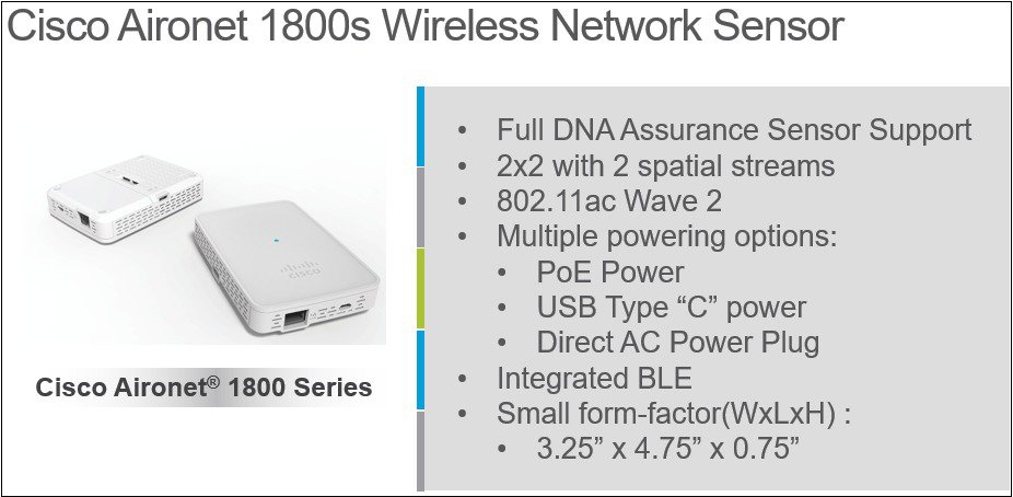
This document covers the Cisco 1815i, 1830, 1850, 2800 & 3800 Series Access Points as a sensor as well as the standalone Cisco Aironet 1800s Wireless Network Sensor.
The Cisco Aironet 1800s wireless network sensor is a part of Cisco's Wireless Service Assurance solution.
Access Points as Sensors
Cisco Access Point Models AP-1815, 1830, 1850, 2800 and 3800 Series can function as a dedicated sensor.
This is a new AP mode type on the controller listed as AP Mode Sensor.
When in sensor mode, the radio inside the Access Point functions much like a client would establishing a connection to the network (as a WLAN client) to allow the following tests/functions to be performed.
Note
When the AP-1815i, 1830 and AP-1850 models are in sensor mode, the ability for the APs to serve the clients is disabled. These models only permit operation in one mode at a time (be it sensor or AP).
AP-2800 and 3800 Series APs contains a special radio known as an XOR radio that can allow the APs to function in a hybrid mode as a sensor. This allows the other radio within the AP to service clients, when in this mode one radio is configured in local mode while the other is configured in sensor mode.
The advantage of sensor mode is to allow the AP to use its own radio (as a client) to test the quality and performance of the network at any time. When the AP is in sensor mode, some functionality on the AP to service clients is limited. This is because one or more of the AP radios are working as a client type device rather than servicing clients.
Sensor mode in the AP is a great solution when you have plenty of APs coverage and can use the AP in that mode. In areas where you need the AP to service clients primarily for performance and/or you have areas where do not wish the AP to act as a sensor, then a dedicated sensor would be recommended.
Note
When the AP is connected as a sensor it connects like a client. If there are any RF issues, then the AP allows the client to access it to pass this traffic up to the DNC.
The Cisco-Aironet AP-1800s is a very small form factor dedicated sensor that can be powered in many different ways through a small sliding module that inserts into the sensor.
Without a PoE module, power can be a local 5 Volt USB supply. Additionally there are modules that allow for a direct AC power supply, as well as PoE operation.
Due to the small size of the sensor, (much smaller than an Access Point) if wall mounting is desired, this sensor uses a small bracket Cisco Part Number AIR-AP-BRACKET-NS
In addition to the 2.4 and 5 GHz radios built into the sensor, there is also a dedicated Bluetooth Low Energy radio as well to future proof the device for possible BLE applications.
Examining the antenna system on the AP-1800s sensor.
The dual band antennas (vertical polarity) are on the side of the sensor while the BLE antenna is mounted on the printed circuit board of the sensor.
DNAC Configuration Prerequisites
Before setting up the sensor in DNAC, the WLC should already be added for brownfield Assurance. This can be confirmed by running "show network assurance summary" on the WLC and checking that no errors are reported and that the "Last Success" time is recent.
To add the WLC for assurance follow these 4 steps:
- Create Site, Building, and Floor hierarchy
- Create a sensor profile and claim sensor
- Add device credentials and run a discovery for the WLC
- Provision the WLC to a site
- Assign discovered AP’s to a floor
Create Site, Building, and Floor hierarchy.
From the main DNA Center screen, select the link under the Design icon to “Add site locations on the network” .
Then select "Add Site" and create a site, building, and floor as necessary for your environment.
Add device Credentials and run discovery.
Device Credentials for the WLC need to be added so that DNAC can configure and enable the Network Assurance Service and learn about devices and clients connected to the WLC. SNMP RW and CLI credentials need to be entered into the Design > Network Settings > Device Credentials tab as seen below.
Once the device credentials are added, a discovery is ran to discover the WLC. From the main DNAC page, select the "Discovery" icon and then enter the necessary IP details for the WLC and select the credentials that were added earlier.
Provision WLC to site.
Next assign the WLC and AP to a site and floor. Select the "Provision WLCs and APs to defined sites" link under the "Provision" icon from the main DNAC page.
From this page, select the tickbox next to the WLC and AP(s) and select “Assign Device to Site” to assign the devices to a building and floor. Ensure that the WLC is assigned to a building and all AP’s are assigned to a floor.
Optinally position the AP on the floor by following the 4 steps below.
The DNAC is now setup for Assurance and AP's are placed on the floor plan.
Sensor Data Flow
When functioning as a sensor, the Sensor AP receives the test suite configuration from the WLC, after it's been created within the DNAC. The actual test results however, do not transverse the WLC as they go directly from the sensor to the DNAC.
DNA Center requires the Sensor package to be installed once the system is online and initial configuration is completed. The "Assurance-Sensor" package needs to be installed from the Application Management catalog. To do this, login to DNAC and select the 'cog' from the top right, select "System Status" and then select the "App Management" tab.
The "Application Management - Packages & Updates" page is displayed, this is where the "Assurance - Sensor" package is listed. Click the "Install" link to start the sensor package installation. This can take up to 40 minutes to complete.
Adding a sensor to DNAC
Ensure that your sensor has network reachability to DNAC. Sensor can be wired or wireless. If sensor is wireless then make sure to prep the network by following the steps in section, "Provisioning an 1800s sensor without Ethernet" below. If sensor is wired ensure it can reach DNAC via wired network.
Next on DNAC we must create a sensor profile. Go to Design -> Network Settings -> Wireless à scroll down to "Sensor Settings" in the window.
Next click the Add button and Provide the "Settings Name", and "Wireless network SSID", and configure it with the appropriate security settings. Save the profile. NOTE: The "Wirless network SSID" is the backhaul SSID which should match the backhaul setup configured on the WLC. See section, " Backhaul Configuration" for steps to setup backhaul on WLC.
Now you must claim the device. If sensor has network reachability to DNAC it will appear in the unclaimed device list. Go to the Provision > Unclaimed devices.
Select the sensor in the unclaimed device list and click on "Sensor Provision". Next you must add the sensor to a floor and choose a sensor profile.
Now the sensor will provision and appear in the Inventory after it is complete. If it is in managed state then it is ready to be setup with a testsuite.
Creating the test suites
ProcedureOnce the Sensor package is installed, navigate to DNA Assurance > Manage > Sensor Driven Tests then select "Add Test" to begin the test suite creation.
Differences between AP Sensor and AP-1800s
The Cisco-Aironet AP-1800s is a dedicated sensor radio in a very small form factor. It is a dedicated sensor only and does not join controller as it uses PnP to find DNAC (sensor package).
Note
Plug and Play happens through the WLC onboarding if it is an Access Point.
Plug and Play happens through the WLC onboarding if it is an Access Point.
Provisioning an 1800s sensor without Ethernet.
When using the 1800s sensor (without the Ethernet module) the sensor would be provisioned over the WLAN by enabling the provisional SSID as shown in the screenshot below.
Once provisioning is enabled (and SSID is set to TFTP) it will create a hidden WLAN called "CiscoSensorProvisioning" and the sensor will join using an EAP-TLS client cert.
This will allow the sensor to find the DNAC IP and is done via DHCP Option 43 or through DNS.
Backhaul Configuration
The backhaul is an SSID you must choose from your existing wlans which will be used by a wireless sensor to connect and communicate with the DNAC. This is how test configurations will be pushed down to your device, or test results pushed back to the DNAC, if you DNAC isn't reachable through the wired network.
To configure the backhaul on the WLC from the UI go to "Management" -> Cloud Services -> Network Assurance -> Sensor. Backhaul configuration will be at the top of the window. Ensure that the SSID name matches an existing wlan and the security also matches.
Enabling DNAC Discovery
ProcedureFor DHCP
You must configure Option 43 with the following ASCII String -example 5A1D;B2;K4;l
<IP address of PnP Server >;J80
For DNS there are two steps:
Step 1 Create a host file on the DNS server that has the host name "PNPSERVER", and the IP address of the PNP server. Step 2 Add option 15 to the DHCP scope and provide the name of your domain name, as well as add option 6 with your DNS server.
Note In the screen below we have also added Option 42 as there is no other way to provide the time.
Example of Scope Options:
For a better understanding of Option 43 and DNS see the following guide https://www.cisco.com/c/en/us/td/docs/solutions/Enterprise/Plug-and-Play/solution/guidexml/b_pnp-solution-guide.html#con_115699
If you need to upgrade the image on an 1852, 2800, or 3800 sensor, this will be done by upgrading the image on the WLC.
If you need to upgrade the 1800s, this can be done via DNAC. To upgrade the 1800S from DNAC first download the image from Cisco's website and add the image to the repository on DNAC. On the main page of DNAC scroll all the way down and click on Image Repository.
Step 3 Click Import Image/SMU
You can add the image by importing the sn1g5-k9w8 image you downloaded from CCO or by providing a url. Click the Import button.
Now image should be in repository. Click on down arrow next to "Cisco 1800S Unified Access Point (Sensor). You should see your imported image listed. You must click on the star next to the imported image in the "Golden Image" column. This will let the repository know which image you want to download to the sensor. Only one star can be selected at a time.
Click on Upgrade Device and you will be taken to the inventory page. Select the 1800S you want to upgrade and at the top of the page choose “Actions” > Update OS Image.
A new window will appear with the sensor selected and the Target Image listed.
Step 4 Choose Now or Laterto upgrade.
Troubleshooting Commands
CLI Commands for troubleshooting. These are to be ran from the sensor AP console (telnet/ssh).
# show dot11 sensor heartbeat statusA heartbeat between DNAC and the sensor occurs every 60 seconds. Run this command to see the status and last success time of the heartbeat. If fail confirm connectivity to DNAC.
# show dot11 sensor test result# This shows the results of the test that the sensor has ran. These results flow directly to the DNAC and do not go thru the WLC.
# show dot11 sensor test configThis shows the configuration that the Sensor has received from the DNAC through the WLC.
# show dot11 sensor synthetic work listThis shows details for each tests that the sensor will execute.
# show dot11 sensor statsLook for "Total Test Cases Ran", "Successful Test Cases" and "Failed Test Cases". This gives in indication of how many tests the sensor has performed and the overall status of those tests. Note this also includes radio stats and does show you if DNAC connectivity is enabled.
# show dot11 sensor scan listThis shows the AP's that the sensor can hear and at what signal level. Only AP's with RSSI of -75 or higher are tested against.
# debug wsa debugUse 'term mon' to view the full debug output from the wsa debug
Detailed Troubleshooting Commands Output
STUB01-SENS3-1815I# show dot11 sensor heartbeat statusHeartbeat Status: Success
Heartback Version: 1
Heartbeat Last Success Time: 2018-01-17 00:53:08.016900
STUB01-SENS3-1815I#	show dot11 sensor test results
Test No: 1, Name: DNS, Time: 2018-01-09 18:48:17.464181
Test Results: {
   "macAddress": "00:a3:8e:16:05:a0",
   "testCompleted": "no",
   "type": "DEDICATED",
   "connectivityStats": {
      "wireless": {
         "status": "SUCCESS",
         "channelWidth": 20,
         "txDataRate": 24000,
         "responseTimesInMillis": {
            "probeRequest": 1,
            "authenticationRequest": 1,
            "handshake": 38,
            "associationRequest": 47
         },
         "snr": 60,
         "rssi": -35,
         "channel": 64
      },
      "DHCP": {
         "status": "SUCCESS",
         "totaltime": 4566,
         "slack": 0,
         "offer": 4202,
         "ack": 118,
         "IP": "10.40.233.115",
         "request": 30,
         "discover": 0,
         "DefaultGWIP": "10.40.239.254",
         "dhcpv6": 0,
         "DNSIP": "208.67.222.222",
         "FailureReason": "DHCP_SUCCESS"
      },
      "DefaultGW": {
         "reachabilityStatus": "yes",
         "reachabilityTimeMillis": "1.616"
      },
      "DNS-Server": {
         "reachabilityStatus": "yes",
         "reachabilityTimeMillis": "1.982"
      }
 <Remainder removed>
STUB01-SENS3-1815I#	show dot11 sensor test config
Test Config Received Time: 2018-01-09 05:57:18.971401
{
    advancedConfig: {
        rssiThreshold: -75
    }
    testConfig:
        {
            name: DNS
            bands: BOTH
            connection: WIRELESS
            frequency: {
                value: 30
                unit: MINUTES
            }
            ssids:
                {
                    username: null
                    validTo: 0
                    numAps: 0
                    id: 0
                    authTypeRcvd: null
                    authType: OTHER
                    ssid: ubcvisitor
                    authProtocol: null
                    eapMethod: null
                    certxferprotocol: HTTP
                    status: ENABLED
                    psk: null
                    bands: 5GHz
                    certfilename: null
                    profileName: eduroam
                    password: ****
                    certstatus: ACTIVE
                    wlc: 10.0.32.145
                    certpassphrase: null
                    numSensors: 0
                    certdownloadurl: null
                    wlanId: 0
                    validFrom: 0
                }
STUB01-SENS3-1815I#	show dot11 sensor synthetic work list
Test 1 Suite 5a331790d07f6f00201c8b0b_afdb243d-67bf-488b-a4d7-d8b59ae93868 DNS AP 00:c8:8b:46:7b:ee radio 1 Wlan eduroam band 802.11a
ssid eduroam frequency 30 freq_unit MINUTES on_demand 0 repeatCountOnFailure 0
Test 2 Suite 5a331790d07f6f00201c8b0b_afdb243d-67bf-488b-a4d7-d8b59ae93868 DNS AP 1c:6a:7a:fc:0c:8e radio 1 Wlan eduroam band 802.11a ssid eduroam frequency 30 freq_unit MINUTES on_demand 0 repeatCountOnFailure 0Test 3 Suite 5a331790d07f6f00201c8b0b_afdb243d-67bf-488b-a4d7-d8b59ae93868 DNS AP 10:05:ca:72:06:de radio 1 Wlan eduroam band 802.11a ssid eduroam frequency 30 freq_unit MINUTES on_demand 0 repeatCountOnFailure 0Test 4 Suite 5a331790d07f6f00201c8b0b_afdb243d-67bf-488b-a4d7-d8b59ae93868 DNS AP 10:05:ca:c4:0b:7e radio 1 Wlan eduroam band 802.11a ssid eduroam frequency 30 freq_unit MINUTES on_demand 0 repeatCountOnFailure 0Test 5 Suite 5a331790d07f6f00201c8b0b_afdb243d-67bf-488b-a4d7-d8b59ae93868 DNS AP 1c:6a:7a:f2:0d:4e radio 1 Wlan eduroam band 802.11a ssid eduroam frequency 30 freq_unit MINUTES on_demand 0 repeatCountOnFailure 0Test 6 Suite 5a331790d07f6f00201c8b0b_afdb243d-67bf-488b-a4d7-d8b59ae93868 DNS AP 1c:6a:7a:fc:00:be radio 1 Wlan eduroam band 802.11a ssid eduroam frequency 30 freq_unit MINUTES on_demand 0 repeatCountOnFailure 0
STUB01-SENS3-1815I#	show dot11 sensor stats
## Network Assurance Sensor Statistics ##
WSA Status: Enabled
NA Connectivity: Not Connected
NA Connectivity I/F: Radio 0  http
NA Server URL: https://10.0.32.42
Auth Type: 10
HTTP Proxy IP:
Backhaul SSID:
Id-token: <BASE64 Encoded String removed>
Port: 80
Total Test Cases Run: 0
Successful Test Cases: 0
Failed Test Cases: 0
Network Assurance 5G Radio Statistics
--------------------------
Host Rx K Bytes: 58643
Host Tx K Bytes: 8097
Unicasts Rx: 267431
Unicasts Tx: 59926
Broadcasts Rx: 53327
Broadcasts Tx: 5550
Beacons Rx: 456662
Beacons Tx: 0
Multicasts Rx: 0
Multicasts Tx: 0
CRC errors: 4178

Network Assurance 2G Radio Statistics
--------------------------
Host Rx K Bytes: 0

Sensor Troubleshooting on the WLC
Copyright © 2018, Cisco Systems, Inc. All rights reserved.


 Feedback
Contact Cisco
- Open a Support Case

- (Requires a Cisco Service Contract)