Supported EPA
The following table lists the supported EPA on the Cisco Catalyst 9800-80 Wireless Controller.
|
PID |
Description |
|---|---|
|
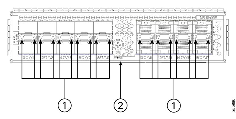
EPA-18X1GE |
Eighteen 1GE-ports that support small form-factor pluggable (SFP) optical transceivers to provide network connectivity. Ports are numbered 0 – 17. See the Supported SFP Transceivers section, for supported transceivers. |
|
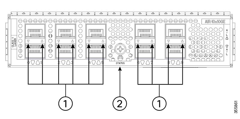
EPA-10X10GE |
Ten 10GE-ports that support small form-factor pluggable (SFP+) optical transceivers to provide network connectivity. Ports are numbered 0 – 9. See Table 3: Supported SFP Transceivers, for supported transceivers. |
|
EPA-1X40GE |
|
|
EPA-2X40GE |
|
|
EPA-1X100GE |
EPA-1X100GE uses a CPAK module to provide network connectivity. See Table 5: Supported CPAK Interface, for supported CPAKs. |
An EPA has two types of LEDs: an A/L (Active/Link) LED for each port on the EPA, and a STATUS LED, as shown in the following figure.
|
1 |
A/L |
2 |
STATUS |
|
Function |
Color or State |
Description |
|---|---|---|
|
A/L (Active/Link) |
Green |
Port is enabled and the link is up. |
|
Amber |
Port is enabled and the link is down. |
|
|
Off |
Port is not enabled. |
|
|
Status |
Green |
EPA is ready and operational. |
|
Amber |
EPA power is on and good, and the EPA is being configured. |
|
|
Off |
EPA power is off. |


 Feedback