KubeVirt-based virtual machine management

KubeVirt-based virtual machine management is a container-native virtualization solution that:

  • enables the deployment of virtual machine-based workloads on Kubernetes infrastructure,

  • provides a unified platform for managing both containerized microservices and virtual machines, and

  • maintains the operational characteristics of traditional virtual environments while leveraging modern cloud-native orchestration.

KubeVirt addresses the need to adopt Kubernetes for existing workloads that are not easily containerized. By packaging virtual machines inside containers, this solution allows network functions to run on the same platform as other cloud-native applications, benefiting from shared infrastructure, management tools, and automated lifecycle processes.


Note


This feature is supported only on Legacy GW (P-GW/SAE-GW/S-GW).

Architecture and key features

The illustration is an example of running VMs inside containers, phasing out OpenStack.

Figure 1. KubeVirt solution

The architecture enables the deployment of VPC-SI and VPC-DI instances on Kubernetes using KubeVirt, bridging traditional VM-based network functions with cloud-native orchestration. This solution provides bare-metal performance characteristics while leveraging the operational advantages of Kubernetes.

Key Features:
  • Declarative infrastructure: Utilizes a YANG-based configuration model with ConfD integration for validation and automated Helm chart generation.

  • High-performance networking: Employs SR-IOV for data plane acceleration and supports flexible network topologies, including management, DI-NET, and service networks.

  • Granular resource control: Enables precise per-instance allocation of CPU, memory, and storage, alongside advanced node affinity and placement policies.

How VPC-SI and VPC-DI deployments work

Summary

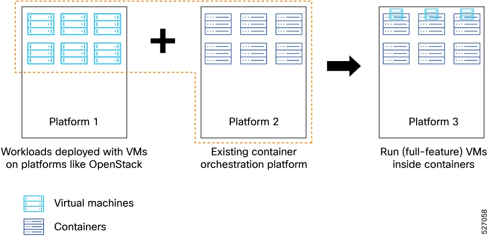
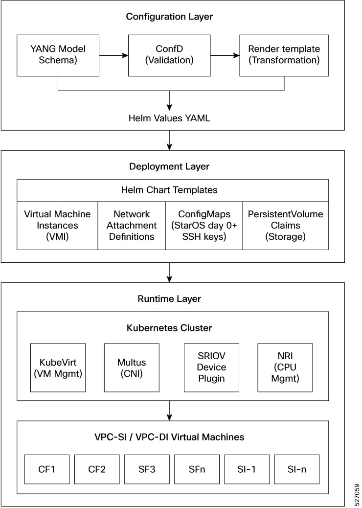
The deployment process uses a model-driven approach to orchestrate virtual machines on Kubernetes. The key components involved in the process are

  • Configuration Layer: Uses YANG models to define infrastructure requirements and validate user input.

  • Deployment Layer: Uses Helm charts to generate Kubernetes resources, including virtual machine definitions and network attachments.

  • Runtime Layer: Uses KubeVirt and Kubernetes to execute the virtual machines and manage networking through Multus and SR-IOV

Workflow

Figure 2. KubeVirt architecture layers

The process involves these stages:

  1. Define the deployment requirements, such as network attachments, resource allocations, and instance configurations, using the YANG-based model.
  2. The configuration system validates the input against the defined schema and stores it in the configuration database.
  3. Helm charts generate the necessary Kubernetes resources, including virtual machine definitions, network attachment definitions, and storage claims.
  4. KubeVirt creates and manages the virtual machine lifecycle on the Kubernetes infrastructure, providing near-native performance for network functions.

Result

The process achieves a standardized and scalable deployment of virtual machine-based network functions within modern Kubernetes environments.

Configure a cluster deployer

Enable the KubeVirt addon on the CNDP inception server.

This section provides sample configurations for the cluster, OpsCenter CEE, VPC-DI, and VPC-SI configurations from the OpsCenter.

Follow these steps and sample configuration to configure inception server and to enable the KubeVirt addon.

Procedure


Step 1

Access the CNDP inception server to configure clusters and enter the manadatory parameters.

Step 2

Enable the addon kubevirt .

Example:

addons cpu-partitioner enabled
 addons cert-manager enabled
 addons kubevirt enabled
 addons ingress bind-ip-address 10.2.4.72
 addons ingress enabled

Step 3

Use this sample configuration to configure StarOS OpsCenter.

Example:

ops-centers epc-core 1
  app-name-override kvpc
  repository-local  kvpc-products-2025.12.10.d02
  netconf-ip        10.2.4.72
  netconf-port      3024
  ssh-ip            10.2.4.72
  ssh-port          3022
  initial-boot-parameters use-volume-claims true
  initial-boot-parameters first-boot-password $8$jnv5psxA9BnwVT1V56qVFoswKbljoTF32AMez2bWiO4=
  initial-boot-parameters auto-deploy false
  initial-boot-parameters single-node true
 exit

Step 4

To deploy VPC-SI or VPC-DI with NUMA aligned resource allocation, use the configuration resource-manager nri-plugin-type topology-aware mandatory cluster configuration .

Note

 
CNDP enables “balloons” as the default NRI plugin type.

Example:

clusters di-kv
 environment di-kv
 configuration cni type cilium
   configuration resource-manager nri-plugin-type topology-aware

Step 5

Enter exit to save and exit all configurations.


Sample configurations

Use these sample configuration to configure Clusters on the CNDP Inception server.
clusters di-kv
 environment di-kv
 configuration cni type cilium
 configuration enable-pod-security-policy false
 configuration pod-subnet   192.117.0.0/16
 configuration service-subnet 10.117.0.0/16
 configuration size         production
 configuration enable-multus true
 configuration allow-insecure-registry true
 configuration restrict-logging false
 configuration enable-ssh-firewall-rules false
configuration resource-manager nri-plugin-type topology-aware
 configuration topology-manager-policy best-effort
 configuration topology-manager-scope pod
 configuration resource-manager infra-flavor small
 configuration cilium enable-legacy-host-routing true
 node-defaults ssh-username cloud-user
 node-defaults ssh-connection-private-key "$8$6yvxg+F8uslTozF7EoHJdnDdyBC9FOTR2M0izsjw4UXmda9D+D/zPZYHNf8joaAhx1i4Kw8X\nTTZzeaxgqXs3YmMUkz3u+JCQ/deRRf1fcjHZqzHsvq8TPFnAmWr6+lse6WZHgbv6F1awv7FU\nE5M6w9eFbuQ3UXC6PvauXvBirE8TjBIGxGgcy+WY3i/1Ts9U5P/k+YGbFYqSLN7UGRK8Z68M\nqMUp6RyKEouAMlh9WMjurHGvQnx2xGI4bvH9EsMDFytyUNA6Zv33S7qp/6FU2GY14zAFtHJ3\nmxzbcM20faxe94/Jj+1pPYfnO0+oPRI0vRsb5Yxr0iwXfdo6PHt/+2BgdVPTQWfk5CMcsww2\nfRJHoh0/xw8mDn8CcBxBFTM2/YPDhiU+Ut9ysfK0TnvUt7FfFCvMzoEerubNkVf3NVHA1+eV\nw274J9aZAmGtPGgTOy5thBzE8w5m2Q9J7EsKr0lpHHwLN7DzmEFRUcvCsqFx1X2c1e1e00pM\n5yDScQn1Fd9VQGE1rk9mNCjw/psngH2jf+kwLNX7zqOwNusZs0w="
 node-defaults host-profile di-kubevirt-host-profile-cilium-isol
 node-defaults initial-boot default-user cloud-user
 node-defaults initial-boot default-user-ssh-public-key "ssh-ed25519 AAAAC3NzaC1lZDI1NTE5AAAAIJX1Gbj1XApuMSK1SRHaw+RuQxfh6QVZRY1dAjIj0VvD svi@cisco.com"
 node-defaults initial-boot default-user-password $8$Ve53md6fjSIM17o1BBwYJrwnwc4Rbn489cwLHg7O21A=
 node-defaults initial-boot default-user-password-expiration-days 9999
 node-defaults initial-boot netplan ethernets eno5
  dhcp4     false
  dhcp6     false
  accept-ra false
 exit
 node-defaults initial-boot netplan ethernets eno6
  dhcp4     false
  dhcp6     false
  accept-ra false
 exit
 node-defaults initial-boot netplan ethernets enp216s0f0
  dhcp4     false
  dhcp6     false
  accept-ra false
 exit
 node-defaults initial-boot netplan ethernets enp216s0f1
  dhcp4     false
  dhcp6     false
  accept-ra false
 exit
 node-defaults initial-boot netplan ethernets enp94s0f0
  dhcp4     false
  dhcp6     false
  accept-ra false
 exit
 node-defaults initial-boot netplan ethernets enp94s0f1
  dhcp4     false
  dhcp6     false
  accept-ra false
 exit
 node-defaults initial-boot netplan bonds bd0
  dhcp4      false
  dhcp6      false
  accept-ra  false
  optional   true
  interfaces [ eno5 eno6 ]
  parameters mode      active-backup
  parameters mii-monitor-interval 100
  parameters fail-over-mac-policy active
 exit
 node-defaults initial-boot netplan vlans vlan3576
  dhcp4     false
  dhcp6     false
  accept-ra false
  id        3576
  link      bd0
 exit
 node-defaults initial-boot netplan vlans vlan64
  dhcp4 false
  dhcp6 false
  id    64
  link  bd0
 exit
 node-defaults k8s max-pods 256
 node-defaults ucs-server cimc certificate rehydrate true
 node-defaults os tuned base-profile latency-performance
 node-defaults os sriov-device-config resource-list-config-map resource-name intel_sriov_dpdk1
  pf-vf-list pf-name enp94s0f0
   bind-driver vfio-pci
   vf-numbers  [ 0 1 2 3 4 5 6 7 8 9 10 11 12 13 14 15 ]
  exit
 exit
 node-defaults os sriov-device-config resource-list-config-map resource-name intel_sriov_dpdk2
  pf-vf-list pf-name enp94s0f1
   bind-driver vfio-pci
   vf-numbers  [ 0 1 2 3 4 5 6 7 8 9 10 11 12 13 14 15 ]
  exit
 exit
 node-defaults os sriov-device-config resource-list-config-map resource-name intel_sriov_dpdk3
  pf-vf-list pf-name enp216s0f0
   bind-driver vfio-pci
   vf-numbers  [ 0 1 2 3 4 5 6 7 8 9 10 11 12 13 14 15 ]
  exit
 exit
 node-defaults os sriov-device-config resource-list-config-map resource-name intel_sriov_dpdk4
  pf-vf-list pf-name enp216s0f1
   bind-driver vfio-pci
   vf-numbers  [ 0 1 2 3 4 5 6 7 8 9 10 11 12 13 14 15 ]
  exit
 exit
 node-defaults os netplan-additions bridges br-mgmt
  dhcp4      false
  dhcp6      false
  gateway4   10.84.108.65
  nameservers search [ mitg-bxb300.cisco.com cisco.com ]
  nameservers addresses [ 10.84.96.130 64.102.6.247 ]
  interfaces [ vlan3576 ]
 exit
 node-defaults os ntp enabled
 node-defaults os ntp servers 10.2.4.71
 exit
 nodes host-1
  k8s node-type       control-plane
  k8s ssh-ip          10.2.4.72
  k8s sshd-bind-to-ssh-ip true
  k8s node-ip         10.2.4.72
  k8s node-labels smi.cisco.com/node-type oam
  exit
  ucs-server ignore-health true
  ucs-server cimc user admin
  ucs-server cimc password $8$u2mpniNtiKHtKZGrZtgJ1VXNBM6vVjKwifWN4yR7Y3g=
  ucs-server cimc remote-management sol enabled
  ucs-server cimc remote-management sol baud-rate 115200
  ucs-server cimc remote-management sol comport com0
  ucs-server cimc remote-management sol ssh-port 2400
  ucs-server cimc ip-address 10.2.4.43
  ucs-server cimc networking ntp enabled
  ucs-server cimc networking ntp servers 10.2.4.71
  exit
  initial-boot netplan vlans vlan64
   dhcp4     false
   addresses [ 10.2.4.72/24 ]
   gateway4  10.2.4.1
   nameservers search [ mitg-bxb300.cisco.com cisco.com ]
   nameservers addresses [ 10.84.96.130 64.102.6.247 ]
  exit
  os tuned enabled
  os additional-ssh-ips [ 10.2.4.72 ]
 exit
 secrets docker-registry regcred
  docker-server   dockerhub.cisco.com
  docker-username tsengalv
  docker-password "$8$qdK+MluRhsYi94avGGpuEd8bDWiPgB8tC2DNl1PhkrLDZACoJ2AHy3oZfMPg9tksXktxSVJJ\nmBMAzyWgjj1HhkzwRQ10Th3fOtHdcGaKmVLmwAPX3VGae5LdyGb1nxW4"
  docker-email    tsengalv@cisco.com
  namespace       epc-core-1
 exit
 ops-centers cee k8s-master-cee
  repository-local        cee-2025.04.1.i16
  sync-default-repository true
  netconf-ip              10.2.4.72
  netconf-port            2024
  ssh-ip                  10.2.4.72
  ssh-port                2022
  ingress-hostname        10.2.4.72.nip.io
  initial-boot-parameters use-volume-claims true
  initial-boot-parameters first-boot-password $8$mqxkpPXDFHZHiwBKEUM9QoXc30wlHcyOagv36ebriWY=
  initial-boot-parameters auto-deploy true
  initial-boot-parameters single-node true
 exit
 ops-centers epc-core 1
  app-name-override kvpc
  repository-local  kvpc-products-2025.12.10.d02
  netconf-ip        10.2.4.72
  netconf-port      3024
  ssh-ip            10.2.4.72
  ssh-port          3022
  initial-boot-parameters use-volume-claims true
  initial-boot-parameters first-boot-password $8$jnv5psxA9BnwVT1V56qVFoswKbljoTF32AMez2bWiO4=
  initial-boot-parameters auto-deploy false
  initial-boot-parameters single-node true
 exit
 addons cpu-partitioner enabled
 addons cert-manager enabled
 addons kubevirt enabled
 addons ingress bind-ip-address 10.2.4.72
 addons ingress enabled
exit

Configure a VPC-SI instance

Deploy a single-instance virtualized packet core gateway on KubeVirt infrastructure.

This task involves providing the necessary configuration parameters to the management interface to initiate the deployment of a VPC-SI instance.

Before you begin

  • Ensure the Kubernetes cluster is operational with KubeVirt enabled.

  • Verify that the required network attachments and storage classes are available.

Procedure


Step 1

Access the management interface and navigate to the deployment configuration section.

Step 2

Define the administrative credentials, hostname, and management network settings for the VPC-SI instance. Refer to the VPC-SI parameters section before specifying parameters for VPC-SI deployment on KubeVirt.

Step 3

Specify the resource requirements, including CPU cores, memory, and persistent storage size.

Step 4

Configure the required network attachments, ensuring the management and service network interfaces are correctly mapped.

Step 5

Apply the node selector configuration to specify the target worker node for the deployment.

Step 6

Commit the configuration to trigger the deployment of the virtual machine.


The system initiates the creation of the virtual machine pod. The VPC-SI instance is provisioned according to the specified parameters. Use this sample configuration to configure VPC-SI from OpsCenter.

deployment
 vpcsi vpcsi1
  staros-config
   admin-login          admin
   admin-password       $8$1Xjm6fJciZlR6s+CTqxzBePdrjPO8lb4F1u5H5q7ODM=
      hostname             epc-core-1
   management-ip        10.84.108.90
   management-prefix    26
   gateway-ip           10.84.108.65
  exit
  staros-params            "FORWARDER_TYPE=iftask\n"
  use-persistent-root-disk true
  node-selector            di-kv-host-1
  cpu cores 12
  memory                   32Gi
  storage size 16Gi
  network-attachments
   management
    type        bridge
    bridge-name br-mgmt
   exit
   service
    sriov-resource smi.cisco.com/intel_sriov_dpdk3
     number-of-ports 2
    exit
    sriov-resource smi.cisco.com/intel_sriov_dpdk4
     number-of-ports 2
    exit
   exit
  exit
 exit
exit
system mode running
exit

What to do next

Verify the status of the deployed VMs using the show kubevirt-vm-status command to confirm all instances have reached the "Ready" state.

VPC-SI parameters

A VPC-SI parameter is a configuration detail that

  • Specifies credentials, resource allocation, and connectivity for a VPC-SI instance.

  • It determines network, storage, and hardware resource assignments.

  • It ensures successful deployment and operation of the StarOS virtual machine.

Key parameters for VPC-SI configuration

The VPC-SI configuration model requires the following key parameters to ensure successful deployment and operation:

Table 1. VPC-SI parameter

Parameter

Description

Admin Login/Password

Credentials for accessing the StarOS instance.

CPU/Memory

Resource allocation for the virtual machine.

Hostname

Unique identifier for the VPC-SI instance.

Management IP/Prefix

Network settings for the management interface.

Network Attachments

Definitions for management and service network connectivity, including SR-IOV resources.

Node selector The node selector is a mandatory requirement for successful virtual machine provisioning. Omitting this parameter will cause the configuration to fail during the commit process, as the system requires a defined target worker node to allocate the necessary physical resources and network attachments.
Persistent Root Disk Enables the use of Persistent Volume Claims (PVCs) for VM storage, ensuring configuration persistence
StarOS parameters Defines specific operational parameters such as FORWARDER_TYPE and CARDSLOT for each function.

Storage Size

Capacity for the persistent root disk.

Configure a VPC-DI instance

Deploy a distributed virtualized packet core instance that consists of multiple Control Functions (CF) and Service Functions (SF).

A VPC-DI instance enables high availability and performance by distributing control and service functions as virtual machines.

Follow these steps to configure a VPC-DI instance:

Before you begin

  • Ensure the Kubernetes cluster is operational with KubeVirt enabled.

  • Verify that the required network attachments (management, DI-NET, and service) and storage classes are available.

  • Prepare the SSH public key for secure instance access.

Follow these steps to configure a VPC-DI instance:

Procedure


Step 1

Access the management interface and navigate to the deployment configuration section.

Step 2

Define the global instance settings, including the hostname, administrative credentials, and management network settings.

Step 3

Configure the Control Functions (CF):

  • Specify the number of CF instances.

  • Assign the required CPU and memory resources for each CF.

  • Map the management and DI-NET network attachments.

Step 4

Configure the Service Functions (SF):

  • Specify the number of SF instances.

  • Assign the required CPU and memory resources for each SF.

  • Map the DI-NET and service network attachments, including SR-IOV resource specifications.

Step 5

Apply the mandatory node selector configuration for each function to ensure proper resource placement.

Step 6

Review the configuration to ensure all network attachments and resource allocations match your design requirements .

Step 7

Commit the configuration to trigger the deployment of the distributed virtual machine pods.


The system initiates the deployment of the CF and SF virtual machines, establishing the distributed packet core instance. This example displays the sample configuration.
deployment
 vpcdi vpcdi2
  staros-config
   admin-login       admin
   admin-password    $8$1Xjm6fJciZlR6s+CTqxzBePdrjPO8lb4F1u5H5q7ODM
   hostname          epc-core-kv-m8-epc-core-1
   management-ip     10.84.21.5
   management-prefix 25
   gateway-ip        10.84.21.1
  exit
  ssh-config
   public-key  "ssh-rsa AAAAB3NzaC1yc2EAAAADAQABAAABAQC8TeEHPynw9xHSvuYw8T9j1yuy0sdME+Smgck+apwwtodGASWZukvNtH361FXIPrJnBBLFzAlLPCIKMi9TAO4jUgieF2g
/aSckxXr2hm4QcN0DvCqLiR6NVUceY957qUK05dz7P0NHl5SyRCJp1Z0RzZRC8eydqiiItfwVswRUhFH5b6nmHwj2Pkz+ivPsI+aNRRJ8Q1hs01E1Wti+pu1lBsdjDqbgYYIqNAd4n1OzbjEZ5aP7oxcIfzTsTVuIJHm8q7P95aifWSrJUxdfWwGc6ZEqCl
+C1GSa1P7dOxQslFb1TCprkUZnbvfp1Q4E5BXNI/JW7yqVUKJu2/yMhxtV root@localhost"
  private-key "-----BEGIN RSA PRIVATE KEY-----\nMIIEowIBAAKCAQEAvE3hBz8p8PcR0r7mMPE
/Y9crstLHTBPkpoHJPmqcMLaHRgEl\nmbpLzbR9+tRVyD6yZwQSxcwJSzwiCjIvUwDuI1IInhdoP2knJMV69oZuEHDdA7wq\ni4kejVVHHmPee6lCtOXc+z9DR5eUskQiadWdEc2UQvHsnaooiLX8FbMEVIRR+W+p\n5h8I9j5M
/orz7CPmjUUSfENYbNNRNVrYvqbtZQbHYw6m4GGCKjQHeJ9Ts24xGeWj\n+6MXCH807E1biCR5vKuz/eWon1kqyVMXX1sBnOmRKgpfgtRkmtT+3TsULJRW9Uwq\na5FGZ2736dUOBOQVzSPyVu8qlVCibtv8jIcbVQIDAQABAoIBACoq9n1885N2gJNF
\nFJ9ZJuzgvnRpJyAuREHVRo+nqBpwhZJzp0vpoBgMlzmYWy1gfOr8yodozZv/d0/5\nNQfNaYaXVD6y1zF8BrwBTSvvpq4f2B6CALUGm8Til+6CRsxCdyGzZ+0LmbFqjG3v
\nPBWfNHFMLCthqa8U78bNmgnx8MJMDPcHiEon2gwzX89SShxCgRWcnyX04n3nmrc5\nXymV74DwLS9EnoWLbtA/GvoQglgn/qc BkMjzh00oxuSOdXeG7DL+e3BoC6vVNqEnp\n2jQkOv8JjNd8mZrxA3n79SqAkFwDhCHy320w6l/E0PP9YuyAkXwR
\n-----END RSA PRIVATE KEY-----"
  exit
  control-functions cf1
   node-selector            kv-m8-node-1
   network-attachments
    management
     type        bridge
     bridge-name di-mgmt
    exit
   dinet 
    sriov-resource smi.cisco.com/intel_sriov_dpdk_node1_phy0
    sriov-resource smi.cisco.com/intel_sriov_dpdk_node1_phy1
    dinet vlan    3587
    dinet mtu     9100
   exit
   cpu cores 8
   memory                   16Gi
   use-persistent-root-disk true
   storage size 16Gi
   staros-params            "CARDSLOT=1\nCARDTYPE=0x40010100
\nDI_INTERFACE=BOND:TYPE:iavf-1,TYPE:iavf-2\nFORWARDER_TYPE=iftask\n"
  exit
  control-functions cf2
   node-selector            kv-m8-node-1
   network-attachments
    management
     type        bridge
     bridge-name di-mgmt
    exit
    dinet 
    sriov-resource smi.cisco.com/intel_sriov_dpdk_node1_phy0
    sriov-resource smi.cisco.com/intel_sriov_dpdk_node1_phy1
    vlan    3587
    mtu     9100
   exit
   cpu cores 8
   memory                   16Gi
   use-persistent-root-disk true
   storage size 16Gi
   staros-params            "CARDSLOT=2\nCARDTYPE=0x40010100\nDI_INTERFACE=BOND:TYPE:iavf-1,TYPE:iavf-2\nFORWARDER_TYPE=iftask\n"
  exit
  service-functions sf1
   node-selector            kv-m8-node-1
   cpu cores 16
   memory                   32Gi
   use-persistent-root-disk true
   staros-params            "CARDSLOT=3\nCARDTYPE=0x42040100
  \nDI_INTERFACE=BOND:TYPE:iavf-1,TYPE:iavf-2\nIFTASK_CORES=50\nIFTASK_MCDMA_CORES=30\nFORWARDER_TYPE=iftask\n"
   network-attachments
    dinet 
    sriov-resource smi.cisco.com/intel_sriov_dpdk_node1_phy0
    sriov-resource smi.cisco.com/intel_sriov_dpdk_node1_phy1
    vlan    3587
    mtu     9100
    exit
    service
     sriov-resource smi.cisco.com/intel_sriov_dpdk_node1_phy0
      number-of-ports 2
     exit
     sriov-resource smi.cisco.com/intel_sriov_dpdk_node1_phy1
      number-of-ports 2
     exit
    exit
   exit
  exit
  service-functions sf2
   node-selector            kv-m8-node-1
   cpu cores 16
   memory                   32Gi
   use-persistent-root-disk true
   staros-params            "CARDSLOT=4\nCARDTYPE=0x42040100\nDI_INTERFACE=BOND:TYPE:iavf-1,TYPE:iavf-2\nFORWARDER_TYPE=iftask\n"
   network-attachments
    dinet 
    sriov-resource smi.cisco.com/intel_sriov_dpdk_node1_phy0
    sriov-resource smi.cisco.com/intel_sriov_dpdk_node1_phy1
    vlan    3587
    mtu     9100
    exit
    service
     sriov-resource smi.cisco.com/intel_sriov_dpdk_node1_phy0
      number-of-ports 2
     exit
     sriov-resource smi.cisco.com/intel_sriov_dpdk_node1_phy1
      number-of-ports 2
     exit
    exit
   exit
  exit
  service-functions sf3
   node-selector            kv-m8-node-1
   cpu cores 16
   memory                   32Gi
   hugepage-size            2Mi
   use-persistent-root-disk true
   staros-params            "CARDSLOT=5\nCARDTYPE=0x42040100\nDI_INTERFACE=BOND:TYPE:iavf-1,TYPE:iavf-2\nIFTASK_CORES=50\nIFTASK_MCDMA_CORES=30\nFORWARDER_TYPE=iftask\n"
   network-attachments
    dinet 
    sriov-resource smi.cisco.com/intel_sriov_dpdk_node0_phy0
    sriov-resource smi.cisco.com/intel_sriov_dpdk_node0_phy1
    vlan    3587
    mtu     9100
    exit
    service
     sriov-resource smi.cisco.com/intel_sriov_dpdk_node0_phy0
      number-of-ports 2
     exit
     sriov-resource smi.cisco.com/intel_sriov_dpdk_node0_phy1
      number-of-ports 2
     exit
    exit
   exit
  exit
  service-functions sf4
   node-selector            kv-m8-node-1
   cpu cores 16
   memory                   32Gi
   use-persistent-root-disk true
   staros-params            "CARDSLOT=6\nCARDTYPE=0x42040100\nDI_INTERFACE=BOND:TYPE:iavf-1,TYPE:iavf-2\nIFTASK_CORES=50\nIFTASK_MCDMA_CORES=30\nFORWARDER_TYPE=iftask\n"
   network-attachments
    dinet 
    sriov-resource smi.cisco.com/intel_sriov_dpdk_node0_phy0
    sriov-resource smi.cisco.com/intel_sriov_dpdk_node0_phy1
    vlan    3587
    mtu     9100
    exit
    service
     sriov-resource smi.cisco.com/intel_sriov_dpdk_node0_phy0
      number-of-ports 2
     exit
     sriov-resource smi.cisco.com/intel_sriov_dpdk_node0_phy1
      number-of-ports 2
     exit
    exit
   exit
  exit
 exit
exit

What to do next

Verify the status of the deployed VMs using the show kubevirt-vm-status command to confirm all instances have reached the "Ready" state.

VPC-DI parameters

A VPC-DI parameter is a configuration detail that specifies credentials, resource allocation, and connectivity for a VPC-DI instance

Key parameters for VPC-DI configuration

The VPC-DI configuration model requires the following key parameters to ensure successful deployment and operation:

Table 2. VPC-DI parameter

Parameter

Description

Admin Login/Password

Credentials for accessing the StarOS instance.

Control Functions (CF)

Defines the control plane instances, including CPU, memory, and management/DI-NET network attachments.

CPU/Memory

Resource allocation for the virtual machine.

DI-NET attachments Specifies the virtual network interfaces used for communication between CF and SF instances.

Hostname

Unique identifier for the VPC-DI instance.

Management IP/Prefix

Network settings for the management interface.

Network Attachments

Definitions for management and service network connectivity, including SR-IOV resources.

Node selector The node selector is a mandatory requirement for successful virtual machine provisioning. Omitting this parameter will cause the configuration to fail during the commit process, as the system requires a defined target worker node to allocate the necessary physical resources and network attachments.
Persistent Root Disk Enables the use of Persistent Volume Claims (PVCs) for VM storage, ensuring configuration persistence

Service Functions (SF)

Defines the data plane instances, including CPU, memory, and DI-NET/service network attachment.

SSH configuration

Optional public key configuration for secure remote access to the distributed instances.

StarOS parameters Defines specific operational parameters such as FORWARDER_TYPE and CARDSLOT for each function.

Storage Size

Capacity for the persistent root disk.