- Preface
- Product Overview
- Preparing for Installation
- Mounting the Access Point
- Installing Other Components
- Troubleshooting
- Appendix A - Access Point Tech Specs References
- Appendix B - Declarations of Conformity and Regulatory Information
- Appendix C - Access Point Pinouts
- Appendix D - Configuring DHCP Option 43
Product Overview
The Cisco Aironet 1570 Series Outdoor Access Point (hereafter called the access point or AP) is a wireless outdoor access point which is designed for use in a variety of network configurations. The access point can be configured, monitored, and operated through a Cisco wireless LAN controller (hereafter called a controller). The controllers use a browser-based management system, a command-line interface (CLI), or the Cisco Prime Infrastructure (PI) network management system to manage the controller and the associated access points. The access point supports hardware-based advanced encryption standard (AES) encryption between wireless nodes to provide end-to-end security. The access point can also be deployed in an autonomous mode and be configured via the CLI.
Access Point Models
The Cisco Aironet 1570 Series Outdoor Access Point is available in three models: AP1572IC, AP1572EC, and AP1572EAC. The features of these models are described in the following table:
Product IDs and Supported Regulatory Domains
Figure 1-1 Product ID Nomenclature of Access Point Models
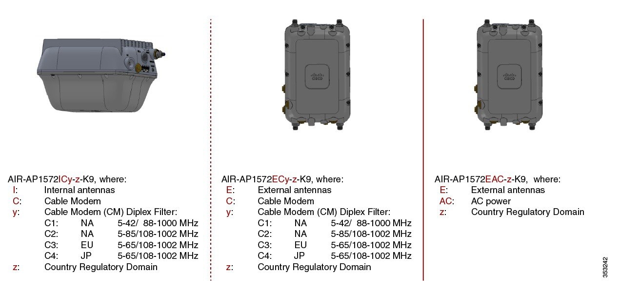
The 1570 series access points have product IDs in the format AIR-AP1572xyy-z-K9, where:
–![]() I—indicating internal antennas.
I—indicating internal antennas.
–![]() E—indicating external antennas.
E—indicating external antennas.
- yy indicates the cable modem type. The models with cable modems can be powered by Power-over-cable or DC power. The options are:
–![]() C1—Indicates Power-over-cable with North American domain (N4) cable modem supporting 5-42/ 54-1000 MHz Diplex Filter, and 8x4 or 16x4 channel bonding options.
C1—Indicates Power-over-cable with North American domain (N4) cable modem supporting 5-42/ 54-1000 MHz Diplex Filter, and 8x4 or 16x4 channel bonding options.
–![]() C2— Indicates Power-over-cable with North American domain (N8) cable modem supporting 5-85/108-1002 MHz Diplex Filter, and 8x4 or 16x8 or 24x8 channel bonding options.
C2— Indicates Power-over-cable with North American domain (N8) cable modem supporting 5-85/108-1002 MHz Diplex Filter, and 8x4 or 16x8 or 24x8 channel bonding options.
–![]() C3—Indicates Power-over-cable with European domain (E8) cable modem supporting 5-65/108-1002 MHz Diplex Filter, and 8x4 or 16x4 or 24x8 channel bonding options.
C3—Indicates Power-over-cable with European domain (E8) cable modem supporting 5-65/108-1002 MHz Diplex Filter, and 8x4 or 16x4 or 24x8 channel bonding options.
–![]() C4—Indicates Power-over-cable with Japanese domain (J8) cable modem supporting 5-65/108-1002 MHz Diplex Filter, and 8x4 or 16x4 or 24x8 channel bonding options.
C4—Indicates Power-over-cable with Japanese domain (J8) cable modem supporting 5-65/108-1002 MHz Diplex Filter, and 8x4 or 16x4 or 24x8 channel bonding options.
–![]() AC— indicates AC power supply, applicable only to external antenna models.
AC— indicates AC power supply, applicable only to external antenna models.
–![]() A, B, C, D, E, F, H, K, M, N, Q, R, S, T, Z
A, B, C, D, E, F, H, K, M, N, Q, R, S, T, Z
Click this URL to browse to a list of countries and regulatory domains supported by the 1570:
www.cisco.com/go/aironet/compliance
Product IDs of Access Point Models in the Cisco Aironet 1570 Series
The following table shows the nine product IDs based on radios, antenna types and powering options:
|
|
|
|---|---|
Parts of each Access Point Model
The parts, ports, and connectors of each side of each AP model is illustrated in the following sections.
Face of the AP
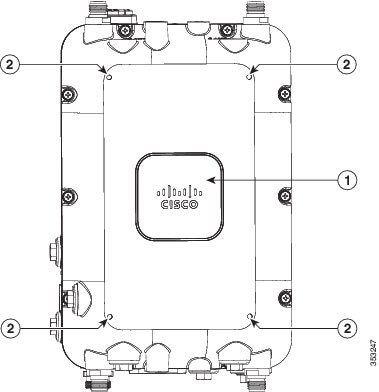
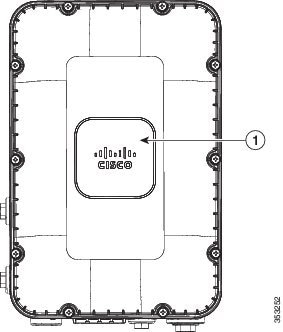
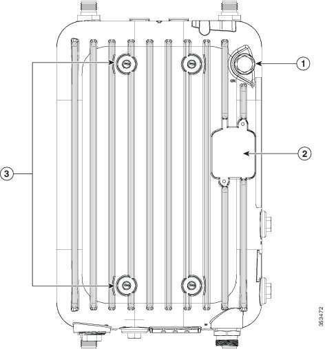
The Face of the access point has the recognizable Cisco logo on it. It is devoid of any ports and connectors. For AP1572EC and AP1572EAC models, the face of the AP has screw holes on it (see Figure 1-2 and Figure 1-3), which support mounting an external module in future applications.
Figure 1-2 Face of the AP, on AP1572EC and AP1572EAC models
|
|
|
Figure 1-3 Face of the AP, on AP1572IC model
|
|
Back of the AP
The Back of the access point is identifiable by the radiation fins, and also the screw holes that are used when mounting the AP on the supported mounting kits. The back of the AP faces upwards when the AP is mounted in a horizontal orientation. The back of the AP on AP1572IC and AP1572EC (see Figure 1-4) is different from that of AP1572EAC (see Figure 1-5).
Figure 1-4 Back of the AP on AP1572IC and AP1572EC
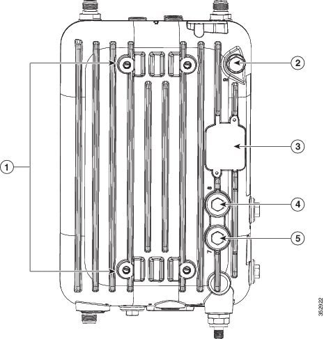
Figure 1-5 Back of the AP on AP1572EAC
|
|
|
||
|
|
Four screw holes for M8 x16mm bolts used to fasten the AP onto mounting kits. |
|
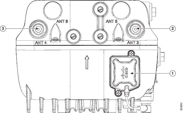
Head of the AP
The Head of the AP faces upwards when the AP is mounted in a vertical orientation. The head of the AP for the internal antenna model is devoid of any ports and connectors (see Figure 1-6), and is different from that of the external antenna models (see Figure 1-7).
Figure 1-6 Head of the AP, on AP1572IC model
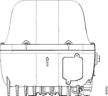
Figure 1-7 Head of the AP, on AP1572EC and AP1572EACmodels
|
|
Spot for mounting the GPS antenna (here, showing the GP antenna mounted). |
|
|
|
|
|
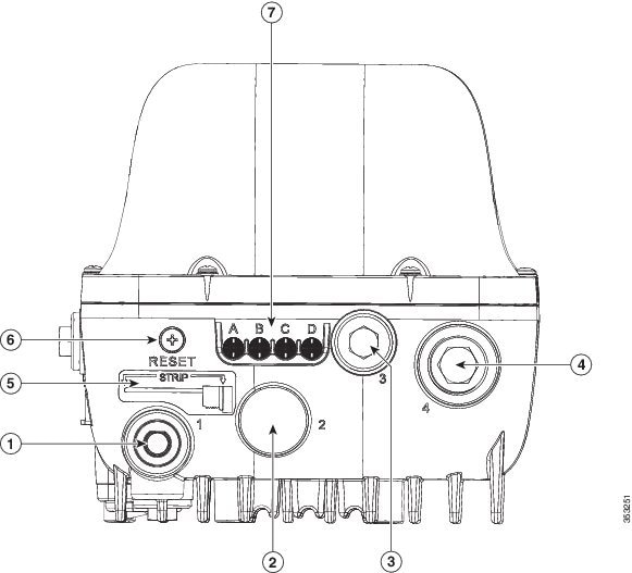
Base of the AP
The Base of the AP is identifiable by the four LED status lights and the Reset button on it. The base of the AP faces downwards when the AP is mounted in a vertical orientation. The base for different AP models is shown in Figure 1-8, Figure 1-9, and Figure 1-10.
Figure 1-8 Base of the AP on AP1572IC model
|
|
|
||
|
|
|
||
|
|
Stinger trim measure for cutting any non-Cisco cable stinger to size |
|
|
|
|
Status LEDs labeled “A” to “D”1 |
|
|
1.The LEDs are visible when AP is installed in both horizontal and vertical orientations. |
Figure 1-9 Base of the AP on AP1572EC model
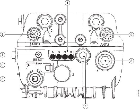
|
|
Status LEDs labeled “A” to “D”2 |
|
|
|
|
|
||
|
|
|
Stinger trim measure for cutting any non-Cisco cable stinger to size |
|
|
|
|
|
2.The LEDs are visible when AP is installed in both horizontal and vertical orientations. |
Figure 1-10 Base of the AP1572EAC model

|
|
|
||
|
|
|
||
|
|
|
||
|
|
Status LEDs labeled “A” to “D”3 |
|
|
3.The LEDs are visible when AP is installed in both horizontal and vertical orientations. |
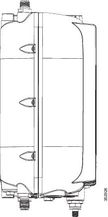
Left Side of the AP
The Left side of the access point is devoid of any ports and connectors. The left side of the AP is similar across all AP models (see Figure 1-11).
Figure 1-11 Left Side of the AP
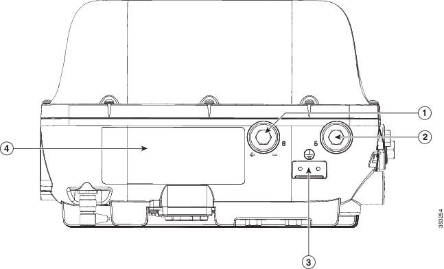
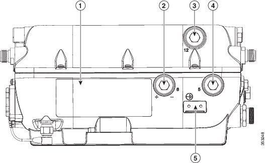
Right Side of the AP
The Right side of the access point is also called the Ground side, because it has the metal surface with the ground strap screw holes. The right side of the AP for the internal antenna model (see Figure 1-12) is different from that of the external antenna models (see Figure 1-13)
Figure 1-12 Right side of the AP, on AP1572IC model
|
|
|
Console port, labeled “5” on the AP4 |
|
|
|
|
|
|
Figure 1-13 Right side of the AP, on AP1572EC and AP1572EAC models
|
|
|
||
|
|
|
Console port, labeled “5” on the AP5 |
|
|
|
|
|
|
 Feedback