- Preface
- Product Overview
- Preparing for Installation
- Mounting the Access Point
- Installing Other Components
- Troubleshooting
- Appendix A - Access Point Tech Specs References
- Appendix B - Declarations of Conformity and Regulatory Information
- Appendix C - Access Point Pinouts
- Appendix D - Configuring DHCP Option 43
Mounting the Access Point
This chapter describes how to install the 1572 access point and contains the following sections:
Unpacking the Access Point
To unpack the access point, follow these steps:
Step 1![]() Open the shipping container and carefully remove the contents.
Open the shipping container and carefully remove the contents.
Step 2![]() Return all packing materials to the shipping container, and save it.
Return all packing materials to the shipping container, and save it.
Step 3![]() Ensure that all items listed in the following sections are included in the shipment. If any item is damaged or missing, notify your authorized Cisco sales representative.
Ensure that all items listed in the following sections are included in the shipment. If any item is damaged or missing, notify your authorized Cisco sales representative.
AP1572IC Package Contents
AP1572EC Package Contents
AP1572EAC Package Contents
- One AP1572EAC series access point
- Grounding Lug kit containing #6 AWG grounding wire with grounding lug (having two holes), and two M4.0 x 10mm screws
- Four 10 inch environmental seal tape
- Oxide inhibitor paste
- Two PG13.5 cable glands
- DC Connector (Cisco Part Number 29-100226-01)
- Cisco product documentation pointer card
Optional AP Hardware
Depending on your requirements, you can order the following optional equipment from Cisco as part of your shipment:
Tools and Hardware Common For All Mounting Options
The tools and hardware required for each mounting option, is listed in the corresponding sections. The following tools and materials are required during various stages of installing the AP, for all mounting options:
- 10 mm open end or box wrench, for M6 bolts
- 13 mm box-end wrench or socket set, for M8 bolts
- Adjustable wrench with opening up to 33 mm and 28 mm socket.
- 0.5 inch or 13 mm wrench (for port plugs)
- Ground lug crimping tool (Panduit CT-720 with CD-720-1 die)
- 6-AWG copper ground wire
- Small flat-screwdriver for DC power connector
- Optional shielded outdoor-rated Ethernet (CAT5e or better) cable with 0.20 to 0.35 in
(0.51 to 0.89 cm) diameter - Optional Ethernet RJ-45 connector and installation tool
- Optional shielded outdoor-rated DC power cable with 0.20 to 0.35 inch (.0.51 to 0.89 cm) diameter, rated at 10 amp, 10-16 V DC cable.
- Optional ground rod, as required by local regulations
- Optional ladder, power lift, rope, or other tools as required
- 5/16" socket wrench (alternative to M8 bolts) for PMK1 mount clamp
- Installation tool for the steel band straps (AIR-BAND-INST-TL=) for fastening the strap brackets when using PMK2 and PMK3.
Typical Access Point Installation Components
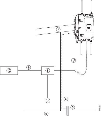
The access point is designed to be installed in an outdoor environment, such as on exterior walls, off cable strands, and on vertical and horizontal poles, such as streetlight poles. Carefully review Figure 3-1 to become familiar with the system components, connectors, indicators, cables, system interconnection, and grounding.

Note![]() The illustrations in this document show all available connections for the access point. Unused connections are capped with a connector plug to ensure the watertight integrity of the access point, except for the AC power entry connector on the in AP1572EAC version access point. Liquid-tight adapters are provided for connector openings, which can be installed before or after deploying the access point.
The illustrations in this document show all available connections for the access point. Unused connections are capped with a connector plug to ensure the watertight integrity of the access point, except for the AC power entry connector on the in AP1572EAC version access point. Liquid-tight adapters are provided for connector openings, which can be installed before or after deploying the access point.
When not using the AC input connector to power the in AP1572EAC version (for example when powering using the Cisco power injector), it is important to cover the AC power entry connector. The correct cap is Remke part number 75-0086 (http://www.remke.com/). This cap is included with the AIR-PWRINJ1500-2= power injector. If you are using PoE directly from a switch or powering via DC, then you will need to order AIR-ACC15-AC-CAP=.
Figure 3-1 Components in a Typical Access Point Installation
|
|
|
||
|
|
Shielded outdoor-rated Ethernet |
|
AC power cord2 |
|
|
|
Power injector3 |
|
|
|
|
||
|
|
|
Note![]() The access point is designed with consideration for resistance to effects of lightning effects on the access point electronics. The access point employs lightning arrestor circuitry on the Ethernet and power ports. On the input Ethernet port, Gas Discharge Tubes (GDT) are used for the Power Entry Module (PEM) to mitigate lightning effect. On the AC power, GDTs are also used along with fuses to mitigate high-current condition. For the DC power, a fuse is used to mitigate high current condition.
The access point is designed with consideration for resistance to effects of lightning effects on the access point electronics. The access point employs lightning arrestor circuitry on the Ethernet and power ports. On the input Ethernet port, Gas Discharge Tubes (GDT) are used for the Power Entry Module (PEM) to mitigate lightning effect. On the AC power, GDTs are also used along with fuses to mitigate high-current condition. For the DC power, a fuse is used to mitigate high current condition.
While not a common practice, the user may want to consider using lightning protection at the antenna ports for added protection. To meet EN/IEC60950-22 (Clause 4.2) requirements, the installer must ensure that additional protection is provided external to this equipment to reduce transient surges from Overvoltage IV to Overvoltage Category II at the AC power input of the access point. The over-voltage and fault-current protection components used to achieve this protection must comply with the IEC 61643 series of standards. To meet CAN/CSA-C22.2 No. 60950-22-07/UL60950-22 requirements, the installer may use alternative components to provide this additional protection. Those components may comply with ANSI/IEEE C62.11, CSA Certification Notice No. 516, CSA C22.2 No. 1, or UL 1449. Suitability of the components for the application must be determined for the intended installation. (For example, some devices are suitable for installation on the load side of the service entrance only, and some are suitable for use with cord-connected equipment only.)
Choosing the Mounting Kit
Personnel installing the access point must understand wireless access points and bridging techniques and grounding methods.
Note ●![]() When mounting an access point horizontally or vertically, ensure that the base of the access point, with the LED indicators, is visible from the ground below the access point.
When mounting an access point horizontally or vertically, ensure that the base of the access point, with the LED indicators, is visible from the ground below the access point.
- Ensure that the access point is mounted in such a way so that all antenna ports and the console port are accessible for future use.
Depending on the particular AP version, the 1570 Series Access Point can be strand, wall, or pole mounted. From the following tables, choose a mounting kit for you access point version based on your mounting scenario.
Strand Mount Kit 1 [AIR-ACCSMK1570-1] |
|
Strand Mount Kit 2 [AIR-ACCSMK1570-2] Strand Mount Kit 3 [AIR-ACCSMK1570-3] |
|
Kit for Wall, Vertical Pole, Horizontal Pole and Off-Angle Pole |
Pole Mount Kit 3 [AIR-ACCPMK1570-3=] |
AP1572EC can be mounted in horizontal and vertical orientations. However, Strand Mount Kit 1 is not supported. |
|
Strand Mount Kit 2 [AIR-ACCSMK1570-2] Strand Mount Kit 3 [AIR-ACCSMK1570-3] |
|
Pole Mount Kit 1 [AIR-ACCPMK1570-1] Pole Mount Kit 2 [AIR-ACCPMK1570-2=] |
|
Pole Mount Kit 2 [AIR-ACCPMK1570-2=] |
|
Kit for Wall, Vertical Pole, Horizontal Pole and Off-Angle Pole |
Pole Mount Kit 3 [AIR-ACCPMK1570-3=] |
AP1572EAC is always mounted in a vertical orientation. It is not mounted on cable strands. |
|
Pole Mount Kit 1 [AIR-ACCPMK1570-1] Pole Mount Kit 2 [AIR-ACCPMK1570-2=] |
|
Pole Mount Kit 2 [AIR-ACCPMK1570-2=] |
Strand Mount Kit 1
The Strand Mount Kit 1 (abbreviated as SMK1) is for mounting the AP directly to a cable strand, when there is no cable bundle. SMK1 consists of two single-piece clamps, which clamp the cable strand across the back of the access point. As the cable strand runs directly across the back surface of the AP, there is no space left between the back surface of the AP and the cable strand.
For instructions on mounting an AP using SMK1, see Strand Mounting Using SMK1.
Strand Mounting Using SMK1
When mounting the access point on a cable strand where you don’t have to accommodate a cable bundle, you can use the SMK1 strand mount kit.
Note![]() The access point must be installed on a cable strand by a professional cable installer.
The access point must be installed on a cable strand by a professional cable installer.
Table 3-1 lists the materials you need to strand mount the AP using SMK1.
Table 3-1 Materials Needed to Mount the AP using SMK1
To mount the access point, follow these steps:
Step 1![]() Hold the AP’s back surface up against the support cable, and ensure that the cable runs through one of the three sets of cable grooves.
Hold the AP’s back surface up against the support cable, and ensure that the cable runs through one of the three sets of cable grooves.
When installing external antennas, which are mounted on the AP using an additional antenna bracket, the AP may tilt to one side due to the uneven weight distribution. To counteract this tilt, three sets of cable grooves are provided on the back surface of the AP. This allows you to run the cable through different sets of the grooves so as to adjust the cable’s position against the AP’s back surface, and thereby counter the tilt.
Figure 3-2 AP Back Surface with Cable Strand in Cable Grooves
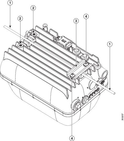
Step 2![]() Clamp the cable using the SMK1 cable clamps. Secure each clamp with two M8 x16mm bolts (with lock washers) on the back surface of the access point (see Figure 3-2). Hand-tighten the bolts to 13 to 15 ft.lbf (17.6 to 20.3 Nm).
Clamp the cable using the SMK1 cable clamps. Secure each clamp with two M8 x16mm bolts (with lock washers) on the back surface of the access point (see Figure 3-2). Hand-tighten the bolts to 13 to 15 ft.lbf (17.6 to 20.3 Nm).
Note![]() The strand support cable and the SMK1 kit together provide the grounding for the access point.
The strand support cable and the SMK1 kit together provide the grounding for the access point.
Step 3![]() Continue with installing antennas, connecting the data cables, grounding the access point, and powering the access point. For information on these, see Chapter4, “Installing Other Components”
Continue with installing antennas, connecting the data cables, grounding the access point, and powering the access point. For information on these, see Chapter4, “Installing Other Components”
Strand Mount Kit 2
The Strand Mount Kit 2 (abbreviated as SMK2) can accommodate a 1.75 inch cable bundle between the support cable strand and the back surface of the AP. The SMK2 allows a distance of 2.42 inches from the back surface of the AP to the center of the cable strand (see Figure 3-4).
The SMK2 consists of these parts:
- Strand mount cable brackets (see Figure 3-5)
- Cable clamps (see Figure 3-5)
- 5/16"-18 bolt for fastening the cable clamps to the strand mount cable bracket (see Figure 3-5)
For instructions on mounting an AP using SMK2, see Strand Mounting Using SMK2.
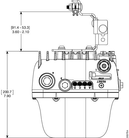
Figure 3-3 SMK2 Cable Clamps and Cable Bracket Assembly Dimensions in inches [and millimeters]
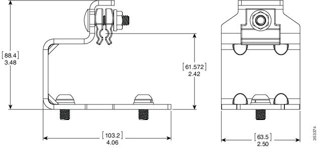
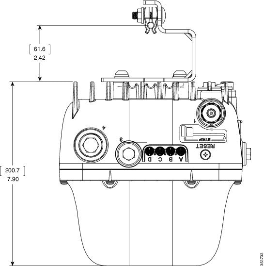
Figure 3-4 AP Mounted Using SMK2 - Dimensions in inches [and millimeters]
Strand Mounting Using SMK2
When mounting the access point on a cable strand where you need to accommodate a cable bundle also, you must use SMK2 strand mount kit.
Note![]() The access point must be installed on a cable strand by a professional cable installer.
The access point must be installed on a cable strand by a professional cable installer.
Table 3-2 lists the materials you need to strand mount the AP using SMK2.
Table 3-2 Materials Needed to Mount the AP using SMK2
To mount the access point, follow these steps:
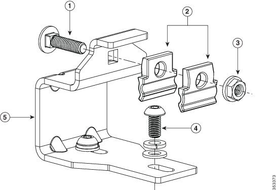
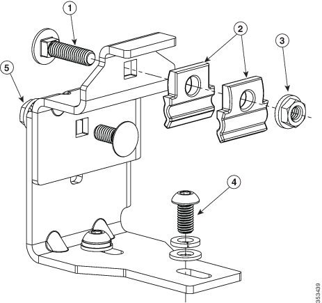
Step 1![]() Assemble the cable clamps to the cable bracket, on both cable brackets (see Figure 3-5). You should hand-tighten the nuts sufficiently enough to only prevent them from falling off.
Assemble the cable clamps to the cable bracket, on both cable brackets (see Figure 3-5). You should hand-tighten the nuts sufficiently enough to only prevent them from falling off.
Figure 3-5 Assembling Cable Clamps on Cable Bracket
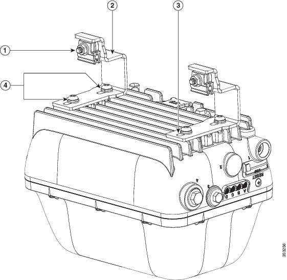
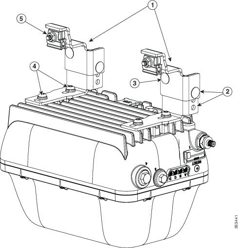
Step 2![]() Secure each cable bracket with two M8 x16 bolts (with lock washers) on the back surface of the access point. (Figure 3-7). Hand-tighten the bolts to 13 to 15 lb.ft (17.6 to 20.3 Nm).
Secure each cable bracket with two M8 x16 bolts (with lock washers) on the back surface of the access point. (Figure 3-7). Hand-tighten the bolts to 13 to 15 lb.ft (17.6 to 20.3 Nm).

Tip![]() When installing external antennas, which are mounted on the AP using an additional antenna bracket, the AP may tilt to one side due to the uneven weight distribution. To counteract this tilt, elongated M8x16 bolt holes are provided on the cable bracket. This allows you to adjust the cable brackets’ position against the AP’s back surface, to cancel the tilt.
When installing external antennas, which are mounted on the AP using an additional antenna bracket, the AP may tilt to one side due to the uneven weight distribution. To counteract this tilt, elongated M8x16 bolt holes are provided on the cable bracket. This allows you to adjust the cable brackets’ position against the AP’s back surface, to cancel the tilt.
Figure 3-6 Cable Brackets Attached to Back Surface of Access Point
5/16"-18 bolt, flange washer, and cable clamps on the cable bracket |
|||
M8 x16mm button-head bolts, which fasten the cable bracket assembly to the AP. |
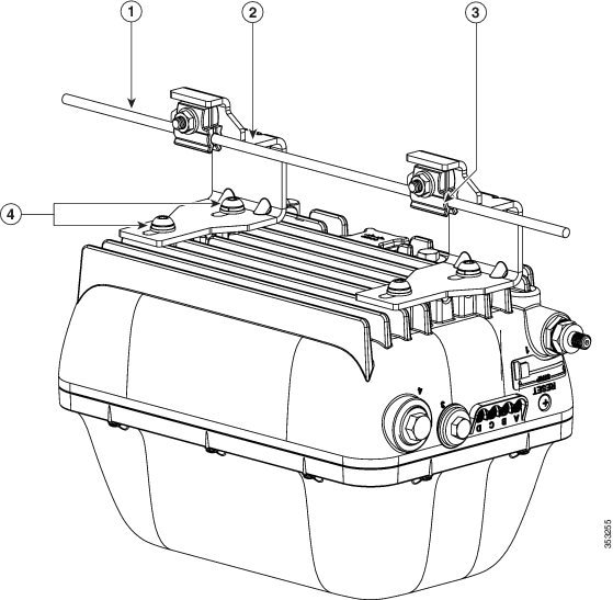
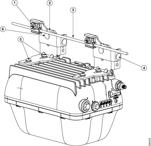
Step 3![]() Place the cable bracket, attached to the AP, on the cable strand, with each pair of cable clamps clamping on to the cable strand. Then, tighten the cable clamps by tightening the two 5/16"-18 nuts to 13 to 15 lb.ft (17.6 to 20.3 Nm). See Figure 3-7.
Place the cable bracket, attached to the AP, on the cable strand, with each pair of cable clamps clamping on to the cable strand. Then, tighten the cable clamps by tightening the two 5/16"-18 nuts to 13 to 15 lb.ft (17.6 to 20.3 Nm). See Figure 3-7.
Figure 3-7 Attaching the Cable Mount Brackets to the Cable Strand
Note![]() During installation, the cable strand/support cable might have to be pulled away from the fiber or cable bundle. Be sure to resecure the cable after installation.
During installation, the cable strand/support cable might have to be pulled away from the fiber or cable bundle. Be sure to resecure the cable after installation.
Note![]() The strand support cable and the SMK2 kit together provide the grounding for the access point.
The strand support cable and the SMK2 kit together provide the grounding for the access point.
Step 4![]() Continue with installing antennas, connecting the data cables, grounding the access point, and powering the access point. For information on these, see Chapter4, “Installing Other Components”
Continue with installing antennas, connecting the data cables, grounding the access point, and powering the access point. For information on these, see Chapter4, “Installing Other Components”
Strand Mount Kit 3
The Strand Mount Kit 3 (abbreviated as SMK3) is used when you have large external antennas mounted to the AP using external antenna mounts such as AIR-ACCAMK1=. The SMK3 can accommodate a 3.6 inch cable bundle between the support cable strand and the back surface of the AP (see Figure 3-9). The SMK3 can also accommodate up to 10 degrees of strand/cable droop.
The SMK3 consists of these parts:
- Height-adjustable strand mount cable brackets (see Figure 3-10)
- Cable clamps (see Figure 3-10)
- Fasteners (see Figure 3-10)
For instructions on mounting an AP using SMK3, see Strand Mounting Using SMK3.
Figure 3-8 SMK3 Cable Clamps and Cable Bracket Assembly Dimensions in inches [and millimeters]
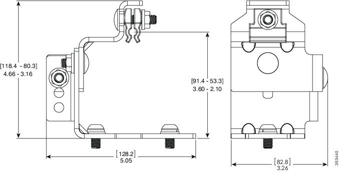
Figure 3-9 AP Mounted Using SMK3 - Dimensions in inches [and millimeters]
Strand Mounting Using SMK3
When mounting the access point on a cable strand where you need to accommodate a cable bundle also, you must use SMK3 strand mount kit.
Note![]() The access point must be installed on a cable strand by a professional cable installer.
The access point must be installed on a cable strand by a professional cable installer.
Table 3-2 lists the materials you need to strand mount the AP using SMK3.
Table 3-3 Materials Needed to Mount the AP using SMK2
To mount the access point, follow these steps:
Step 1![]() Assemble the cable clamps to the cable bracket, on both cable brackets (see Figure 3-10).
Assemble the cable clamps to the cable bracket, on both cable brackets (see Figure 3-10).
Set the height of the cable brackets as required.
You should hand-tighten the cable clamp nuts sufficiently enough to only prevent them from falling off.
Figure 3-10 Assembling Cable Clamps on Cable Bracket
5/16"-18 bolt and nut for the height-adjustable cable bracket |
Step 2![]() Secure each cable bracket with two M8 x16 bolts (with lock washers) on the back surface of the access point. (Figure 3-12). Hand-tighten the bolts to 13 to 15 lb.ft (17.6 to 20.3 Nm).
Secure each cable bracket with two M8 x16 bolts (with lock washers) on the back surface of the access point. (Figure 3-12). Hand-tighten the bolts to 13 to 15 lb.ft (17.6 to 20.3 Nm).
Tip![]() When installing external antennas, which are mounted on the AP using an additional antenna bracket, the AP may tilt to one side due to the uneven weight distribution. To counteract this tilt, elongated M8x16 bolt holes are provided on the cable bracket. This allows you to adjust the cable brackets’ position against the AP’s back surface, to cancel the tilt.
When installing external antennas, which are mounted on the AP using an additional antenna bracket, the AP may tilt to one side due to the uneven weight distribution. To counteract this tilt, elongated M8x16 bolt holes are provided on the cable bracket. This allows you to adjust the cable brackets’ position against the AP’s back surface, to cancel the tilt.
Figure 3-11 Cable Brackets Attached to Back Surface of Access Point
Step 3![]() Place the cable bracket, attached to the AP, on the cable strand, with each pair of cable clamps clamping on to the cable strand. Then, tighten the cable clamps by tightening the two 5/16"-18 nuts to 13 to 15 lb.ft (17.6 to 20.3 Nm). See Figure 3-12.
Place the cable bracket, attached to the AP, on the cable strand, with each pair of cable clamps clamping on to the cable strand. Then, tighten the cable clamps by tightening the two 5/16"-18 nuts to 13 to 15 lb.ft (17.6 to 20.3 Nm). See Figure 3-12.
Figure 3-12 Attaching the Cable Mount Brackets to the Cable Strand
Note![]() During installation, the cable strand/support cable might have to be pulled away from the fiber or cable bundle. Be sure to resecure the cable after installation.
During installation, the cable strand/support cable might have to be pulled away from the fiber or cable bundle. Be sure to resecure the cable after installation.
Note![]() The strand support cable and the SMK2 kit together provide the grounding for the access point.
The strand support cable and the SMK2 kit together provide the grounding for the access point.
Step 4![]() Continue with installing antennas, connecting the data cables, grounding the access point, and powering the access point. For information on these, see Chapter4, “Installing Other Components”
Continue with installing antennas, connecting the data cables, grounding the access point, and powering the access point. For information on these, see Chapter4, “Installing Other Components”
Pole Mount Kit 1
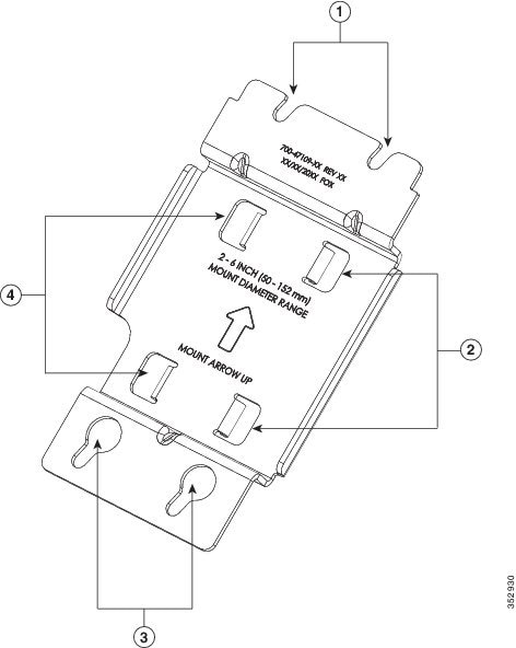
The Pole Mount Kit 1 (abbreviated as PMK1) can be used to vertically mount the AP on a vertical pole. Poles of diameter ranging from 2 to 6 inches (50 to 152 mm) are supported. PMK1 consists of a one-piece pole mount bracket, and two adjustable steel band straps.
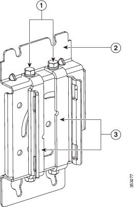
Figure 3-13 shows the one-piece pole mount bracket PMK1 kit.
Note![]() PMK1 maintains a very low profile with only a 1.0 inch clearance between the pole and the AP.
PMK1 maintains a very low profile with only a 1.0 inch clearance between the pole and the AP.
Figure 3-13 PMK1 One-Piece Pole Mounting Bracket
|
|
Key hole slots for the four M8 x 12mm hex head bolts, using which the AP is mounted on PMK1 |
|
For mounting the AP using PMK1, see Pole Mounting Using PMK1.
Pole Mounting Using PMK1
You can use PMK1 for vertically mounting the AP on vertical poles, with diameters ranging from 2 to 6 inches (50 to 152 mm). Ensure that you have the materials listed in Table 3-4 to mount the AP.
Table 3-4 Materials Needed to Mount the AP using PMK1
Two stainless steel band straps (adjustable to fit poles of 2– 6 inches, 50–152 mm). These band straps have a pull-lock-tighten system. |
|
5/16 socket head wrench for tightening the steel band straps |
A typical installation using PMK1 is show in Figure 3-15.
To mount the access point onto a vertical pole or streetlight pole, follow these steps:
Step 1![]() Select a mounting location on the pole to mount the access point.
Select a mounting location on the pole to mount the access point.
Note![]() If you will be using a streetlight power tap adapter, position the access point within 3 ft (1 m) of the outdoor light control. The AC/DC adapter must be used with street light power tap.
If you will be using a streetlight power tap adapter, position the access point within 3 ft (1 m) of the outdoor light control. The AC/DC adapter must be used with street light power tap.
Step 2![]() Slide the two band straps through the top and bottom set of mounting slots on the mounting brackets, and then hold the bracket up against the pole.
Slide the two band straps through the top and bottom set of mounting slots on the mounting brackets, and then hold the bracket up against the pole.
Step 3![]() Wrap the band straps around the pole, lock them and then lightly tighten the clamps using the 5/16 socket head wrench. Only tighten them enough to keep the bracket from sliding down the pole.
Wrap the band straps around the pole, lock them and then lightly tighten the clamps using the 5/16 socket head wrench. Only tighten them enough to keep the bracket from sliding down the pole.
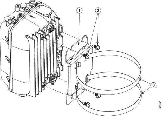
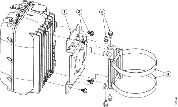
Step 4![]() Screw a M8 x 12mm hex head bolt into each of the four bolt holes on the back side of the access point. Do not screw the bolt in all the way. Leave a gap of about 0.13 inch (3.3 mm). Refer Figure 3-14.
Screw a M8 x 12mm hex head bolt into each of the four bolt holes on the back side of the access point. Do not screw the bolt in all the way. Leave a gap of about 0.13 inch (3.3 mm). Refer Figure 3-14.
Step 5![]() Position the four bolts on the access point into the bracket’s keyhole slots. Check to be sure that the access point is properly seated in the slots. Refer Figure 3-14.
Position the four bolts on the access point into the bracket’s keyhole slots. Check to be sure that the access point is properly seated in the slots. Refer Figure 3-14.
Note![]() Ensure that the access point should be positioned with its base facing the ground so that the LEDs on the base can be viewed from the ground.
Ensure that the access point should be positioned with its base facing the ground so that the LEDs on the base can be viewed from the ground.
Step 6![]() Using a 13 mm wrench, tighten the four M8 bolts that connect the access point to the bracket to a torque of 13 to 15 lb.ft (17.6 to 20.3 Nm).
Using a 13 mm wrench, tighten the four M8 bolts that connect the access point to the bracket to a torque of 13 to 15 lb.ft (17.6 to 20.3 Nm).
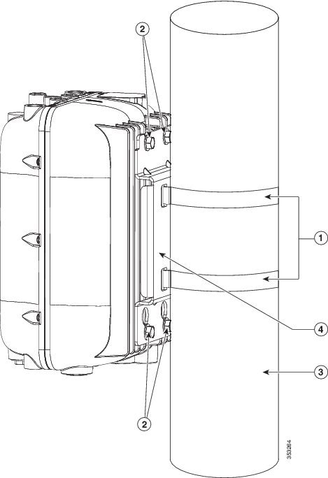
Step 7![]() Tighten the band straps with the wrench so that the access point does not slide on the pole. Ensure that the straps are tight enough to not let the AP move. Refer Figure 3-15.
Tighten the band straps with the wrench so that the access point does not slide on the pole. Ensure that the straps are tight enough to not let the AP move. Refer Figure 3-15.
Step 8![]() Continue with installing antennas, connecting the data cables, grounding the access point, and powering the access point. For information on these, see Chapter4, “Installing Other Components”
Continue with installing antennas, connecting the data cables, grounding the access point, and powering the access point. For information on these, see Chapter4, “Installing Other Components”
Figure 3-14 Exploded view of PMK1 used to Vertically Mount an AP1572E
|
|
|
||
|
|
|
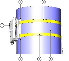
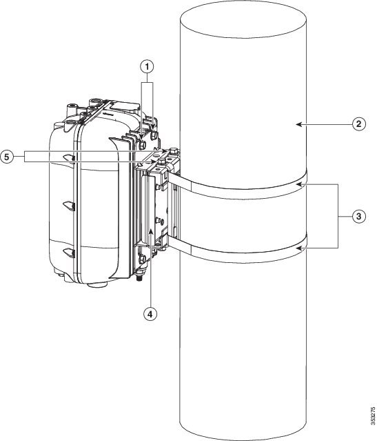
Figure 3-15 AP1572E Vertically Mounted on Vertical Pole with PMK1
|
|
|
||
|
|
|
Pole Mount Kit 2
The Pole Mount Kit 2 (abbreviated as PMK2) can be used to vertically mount the AP on a vertical pole, a horizontal pole, or on an off-angle pole. Poles of diameter ranging from 2 to 16 inches are supported. This kit can also be used to vertically mount the AP on a wall.
The PMK2 consists of these parts:
- A wall mount bracket, for vertical mounting on walls (see Figure 3-17)
- A pivot bracket (see Figure 3-18)
- Two strap brackets (see Figure 3-19)
- Two adjustable steel band straps
The Pivot Bracket and the Strap Brackets, are used only when mounting the AP on poles.
By itself, the Wall Mount Bracket, is used for vertical mounting on the AP on walls. For more information, see Wall Mounting Using PMK2. When mounting the AP on poles, the Wall Mount Bracket is used along with the Pivot Bracket and the Strap Brackets.
When all three pieces of the PKM2 kit are assembled (see Figure 3-20), the pivot bracket attached to the wall mount bracket allows reorienting the PMK2 mount assembly by up to 90 degrees from vertical. This allows the AP to be vertically mounted on horizontal poles and off-angle poles. The pivot bracket also provides three sets of bolt holes for the strap brackets to attach, thereby supporting three pole diameter ranges: 2 to 6, 6 to 11, and 11 to 16 inches (see Figure 3-18 and Figure 3-19).
For more information on vertically mounting the AP on poles, see Pole Mounting Using PMK2.
You can choose to discard the pivot bracket and attach the strap brackets directly to the wall mount bracket. However, this assembly can be used for vertically mounting the AP only on vertical poles, with diameter ranging from 4 to 8 inches. See Vertically Mounting Without Pivot Bracket For 4 to 8 inches Vertical Pole.
Figure 3-16 PMK2 Wall Mount Bracket Dimensions in inches [and millimeters]
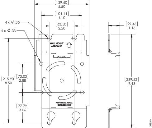
Figure 3-17 PMK2 Wall Mount Bracket
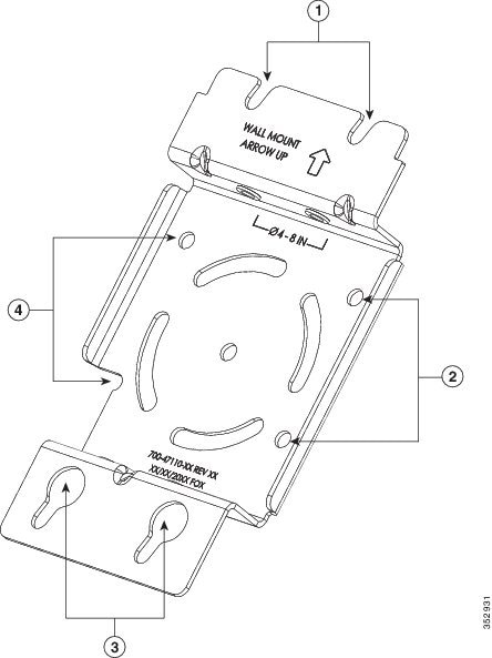
Figure 3-18 Pivot Bracket with Adjustment Hole Locations
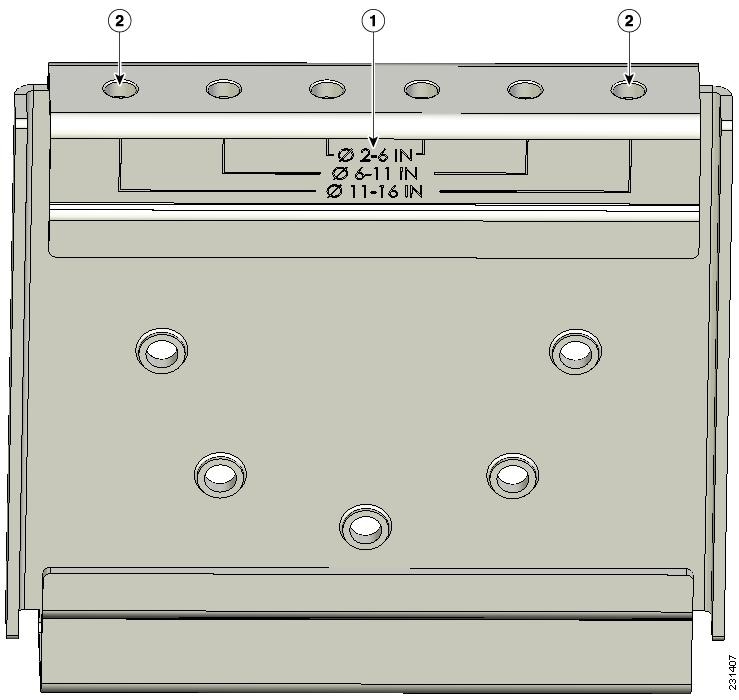
Figure 3-19 Strap Brackets assembled on the Pivot Bracket
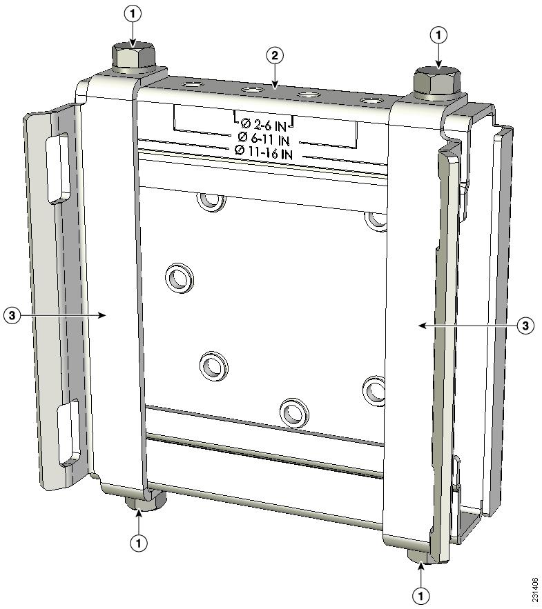
Strap bracket (shown positioned for 11 to 16 inch diameter pole) |
Figure 3-20 All Three Parts of PMK2 Assembled 5
Pole Mounting Using PMK2
You can use PMK2 for vertically mounting the AP on vertical poles, horizontal poles, and off-angle poles of diameter ranging from 2 to 16 inches. For more information, see Pole Mount Kit 2.
Table 3-5 Materials Needed to Mount the AP using PMK2
Tip![]() If you need to vertically mount the AP on vertical poles of diameter ranging from 5 to 8 inches (127 to 203 mm), you can use PMK2 without the pivot bracket. See Vertically Mounting Without Pivot Bracket For 4 to 8 inches Vertical Pole
If you need to vertically mount the AP on vertical poles of diameter ranging from 5 to 8 inches (127 to 203 mm), you can use PMK2 without the pivot bracket. See Vertically Mounting Without Pivot Bracket For 4 to 8 inches Vertical Pole
To mount the AP using PMK2, follow these steps.
Step 1![]() Position the strap brackets on the pivot bracket according to the diameter of the pole. Secure each strap bracket with two M8 x16 bolts (with lock washers) and M8 nuts (Figure 3-21). Tighten the bolts to 13 to 15 lb.ft (17.6 to 20.3 Nm).
Position the strap brackets on the pivot bracket according to the diameter of the pole. Secure each strap bracket with two M8 x16 bolts (with lock washers) and M8 nuts (Figure 3-21). Tighten the bolts to 13 to 15 lb.ft (17.6 to 20.3 Nm).
Step 2![]() Select a mounting location on the pole to mount the access point.
Select a mounting location on the pole to mount the access point.
–![]() For vertical poles, position the strap and pivot brackets assembly as shown in Figure 3-24. The pivot bracket is oriented vertically.
For vertical poles, position the strap and pivot brackets assembly as shown in Figure 3-24. The pivot bracket is oriented vertically.
–![]() For horizontal poles, position the strap and pivot brackets assembly as shown in Figure 3-25. The pivot bracket is oriented horizontally.
For horizontal poles, position the strap and pivot brackets assembly as shown in Figure 3-25. The pivot bracket is oriented horizontally.
Note![]() If you will be using a streetlight power tap adapter, position the access point within 3 ft (1 m) of the outdoor light control
If you will be using a streetlight power tap adapter, position the access point within 3 ft (1 m) of the outdoor light control
Step 3![]() Mount the strap and pivot brackets assembly at the mounting location on the pole, using the two band straps (refer Figure 3-23), as follows:
Mount the strap and pivot brackets assembly at the mounting location on the pole, using the two band straps (refer Figure 3-23), as follows:
–![]() For pole diameters more than 3.5 inch (89 mm), loop each metal band strap twice through the slots on the strap brackets (see Figure 3-22). Follow the instructions provided with the band strap tool (BAND IT) (AIR-BAND-INST-TL=).
For pole diameters more than 3.5 inch (89 mm), loop each metal band strap twice through the slots on the strap brackets (see Figure 3-22). Follow the instructions provided with the band strap tool (BAND IT) (AIR-BAND-INST-TL=).
–![]() For pole diameters equal to or less than 3.5 inch (89 mm), loop each metal band strap twice through the slots on the strap brackets and also through the narrow space between the pole clamp bracket and the strap brackets (see Figure 3-22). This ensures maximum holding strength, especially for extreme environments. Following the instructions provided with the band strap tool (BAND IT) (AIR-BAND-INST-TL=).
For pole diameters equal to or less than 3.5 inch (89 mm), loop each metal band strap twice through the slots on the strap brackets and also through the narrow space between the pole clamp bracket and the strap brackets (see Figure 3-22). This ensures maximum holding strength, especially for extreme environments. Following the instructions provided with the band strap tool (BAND IT) (AIR-BAND-INST-TL=).

Step 4![]() Tighten the metal band straps using the banding strap tool (BAND IT) (Cisco AIR-BAND-INST-TL=) by following the operating instructions in the box with the tool. Ensure that the metal band straps are as tight as possible.
Tighten the metal band straps using the banding strap tool (BAND IT) (Cisco AIR-BAND-INST-TL=) by following the operating instructions in the box with the tool. Ensure that the metal band straps are as tight as possible.
Step 5![]() Hold the wall mount bracket against the pivot bracket such that the curved slots and the bolt holes line up.
Hold the wall mount bracket against the pivot bracket such that the curved slots and the bolt holes line up.
Step 6![]() Insert and hand-tighten four M8 x16 bolts (with flat and lock washers) into the bolt holes. Do not over tighten.
Insert and hand-tighten four M8 x16 bolts (with flat and lock washers) into the bolt holes. Do not over tighten.
Step 7![]() For off-angle poles, you can now rotate the mounting bracket as required. Rotate to ensure that the AP will be oriented vertically and that the LEDs on the base of the AP will be visible from the ground.
For off-angle poles, you can now rotate the mounting bracket as required. Rotate to ensure that the AP will be oriented vertically and that the LEDs on the base of the AP will be visible from the ground.
Note![]() The wall mount bracket can be rotated to up to 45o from the vertical, while attached to the pivot bracket. This allows you to compensate for the tilt of off-angle poles, such as tilted streetlight arms.
The wall mount bracket can be rotated to up to 45o from the vertical, while attached to the pivot bracket. This allows you to compensate for the tilt of off-angle poles, such as tilted streetlight arms.
Step 8![]() Make final adjustments, if needed, to the top edge of the wall mount bracket so that it is horizontal. Ensure such that the AP will be oriented vertically and that the LEDs on the base of the AP will be visible from the ground. Then tighten the bolts four bolts to 13 to 15 lb.ft (17.6 to 20.3 Nm).
Make final adjustments, if needed, to the top edge of the wall mount bracket so that it is horizontal. Ensure such that the AP will be oriented vertically and that the LEDs on the base of the AP will be visible from the ground. Then tighten the bolts four bolts to 13 to 15 lb.ft (17.6 to 20.3 Nm).
Step 9![]() Screw an M8 bolt into each of the four bolt holes on the back side of the access point. Do not screw the bolt in all the way. Leave a gap of about 0.13 inch (3.3 mm).
Screw an M8 bolt into each of the four bolt holes on the back side of the access point. Do not screw the bolt in all the way. Leave a gap of about 0.13 inch (3.3 mm).
Step 10![]() Position the four bolts on the access point into the bracket’s keyhole slots. Check to ensure that the access point is properly seated in the slots. (see Figure 3-26)
Position the four bolts on the access point into the bracket’s keyhole slots. Check to ensure that the access point is properly seated in the slots. (see Figure 3-26)
Step 11![]() Using a 13 mm open-end or socket wrench, tighten the four bolts that connect the access point to the bracket to a torque of 13 to 15 lb.ft (17.6 to 20.3 Nm).
Using a 13 mm open-end or socket wrench, tighten the four bolts that connect the access point to the bracket to a torque of 13 to 15 lb.ft (17.6 to 20.3 Nm).
Step 12![]() Continue with installing antennas, connecting the data cables, grounding the access point, and powering the access point. For information on these, see Chapter4, “Installing Other Components”
Continue with installing antennas, connecting the data cables, grounding the access point, and powering the access point. For information on these, see Chapter4, “Installing Other Components”
Figure 3-21 Strap Brackets attached to Pivot Bracket
Strap bracket (shown positioned for 11 to 16 inch diameter pole) |
|||
Figure 3-22 Spaces and Slots for Looping Band Straps
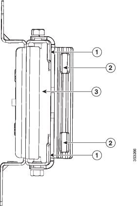
Figure 3-23 Strap Bracket-Pivot Bracket Assembly Mounted on Pole with Band Straps
|
|
|
||
|
|
|
Figure 3-24 Wall Bracket Attached to Strap Bracket-Pivot Bracket Assembly for Vertical Pole
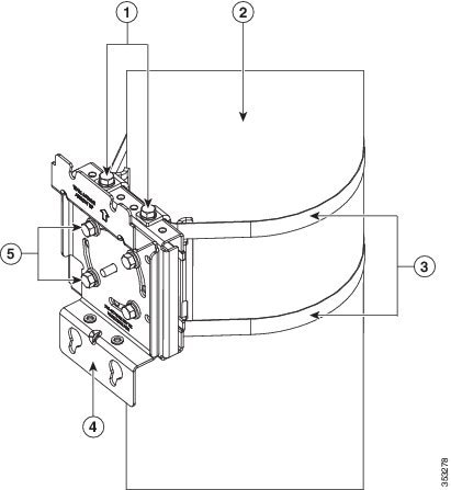
Figure 3-25 Wall Bracket attached to Strap Bracket-Pivot Bracket Assembly for Horizontal Pole
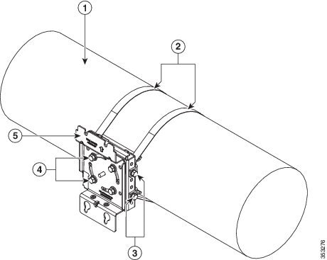
Figure 3-26 AP1572E Vertically Mounted on Vertical Pole using PMK2 Kit
Vertically Mounting Without Pivot Bracket For 4 to 8 inches Vertical Pole
If you need to vertically mount the AP on vertical poles of diameter ranging from 4 to 8 inches (102 to 203 mm), you can use PMK2 without the pivot bracket. In this case, you fix the PMK2 strap brackets directly to the PMK2 wall mount bracket.
Step 1![]() Position the strap brackets on the wall mount bracket as shown in Figure 3-27.
Position the strap brackets on the wall mount bracket as shown in Figure 3-27.
Step 2![]() Secure each strap bracket with two M8 x16 bolts (with lock washers). Tighten the bolts to 13 to 15 lb.ft (17.6 to 20.3 Nm).
Secure each strap bracket with two M8 x16 bolts (with lock washers). Tighten the bolts to 13 to 15 lb.ft (17.6 to 20.3 Nm).
Step 3![]() Select a mounting location on the pole to mount the access point.
Select a mounting location on the pole to mount the access point.
Step 4![]() Mount the strap and wall-mount brackets assembly to the pole using the two metal band straps (refer Figure 3-28). Ensure such that the AP will be oriented vertically and that the LEDs on the base of the AP will be visible from the ground.
Mount the strap and wall-mount brackets assembly to the pole using the two metal band straps (refer Figure 3-28). Ensure such that the AP will be oriented vertically and that the LEDs on the base of the AP will be visible from the ground.
Loop each band strap twice through the slots on the strap bracket, and then tighten the band straps using the band strap tool (BAND IT) (AIR-BAND-INST-TL=). Follow the operating instructions provided by tool’s manufacturer to tighten the metal bands to full tension.
Note![]() Installing and final tightening of the band straps are done together. After the metal bands are tightened to full tension, the position of the AP on the pole cannot be adjusted unless the metal bands are cut or disassembled.
Installing and final tightening of the band straps are done together. After the metal bands are tightened to full tension, the position of the AP on the pole cannot be adjusted unless the metal bands are cut or disassembled.
Step 5![]() Screw an M8 x 12 mm bolt into each of the four bolt holes on the back side of the access point. Do not screw the bolt in all the way. Leave a gap of about 0.13 inch (3.3 mm).
Screw an M8 x 12 mm bolt into each of the four bolt holes on the back side of the access point. Do not screw the bolt in all the way. Leave a gap of about 0.13 inch (3.3 mm).
Step 6![]() Position the four bolts on the access point into the bracket’s keyhole slots. Check to ensure that the access point is properly seated in the slots. (refer Figure 3-28)
Position the four bolts on the access point into the bracket’s keyhole slots. Check to ensure that the access point is properly seated in the slots. (refer Figure 3-28)
Step 7![]() Using a 13mm wrench, tighten the four bolts that connect the access point to the bracket to a torque of 13 to 15 lb.ft (17.6 to 20.3 Nm).
Using a 13mm wrench, tighten the four bolts that connect the access point to the bracket to a torque of 13 to 15 lb.ft (17.6 to 20.3 Nm).
Step 8![]() Continue with installing antennas, connecting the data cables, grounding the access point, and powering the access point. For information on these, see Chapter4, “Installing Other Components”
Continue with installing antennas, connecting the data cables, grounding the access point, and powering the access point. For information on these, see Chapter4, “Installing Other Components”
Figure 3-27 PMK2 Strap Brackets directly attached to PMK2 Wall Mount Bracket
|
|
M8x16mm bolts used to attach the strap brackets to the wall mount bracket |
|
|
|
|
|
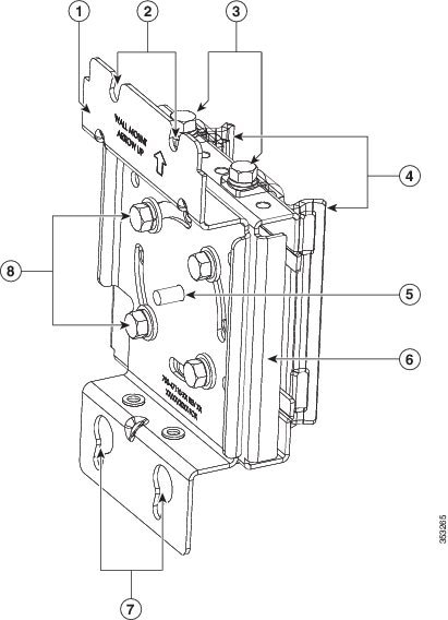
Figure 3-28 Exploded view of PMK2 mount without Pivot Bracket for 4 to 8 inches Vertical Pole
|
|
|
M8x12mm bolts, used to fasten the AP to the PMK2 wall mount bracket |
|
|
|
M8x16mm bolts used to attach the strap brackets to the wall mount bracket |
|
Wall Mounting Using PMK2
To vertically mount the AP on a wall, you can use PMK2 without the pivot bracket and the strap brackets. Using only the PMK2 wall mount bracket, you can vertically mount the AP on a wall. For more information about PMK2, see Pole Mount Kit 2.
Table 3-6 Materials Needed to Mount the AP on a Wall using PMK2
(22.7 kg) static weight, and should conform to all local codes and regulations.
To mount the access point on a vertical wall, follow these instructions:
Step 1![]() Use the wall mount bracket as a template to mark four screw hole locations on your mounting surface.
Use the wall mount bracket as a template to mark four screw hole locations on your mounting surface.
The recommended screw hole locations are shown in Figure 3-17.
The dimensions of the wall mount bracket are shown in Figure 3-16.
Step 2![]() Using four screws and optional screw anchors, attach the wall mount bracket to the wall. Ensure that the four screws are fully tightened.
Using four screws and optional screw anchors, attach the wall mount bracket to the wall. Ensure that the four screws are fully tightened.
Note![]() If necessary, use suitable screw anchors and an exterior-grade plywood backboard to mount the access point to stucco, cement, or drywall.
If necessary, use suitable screw anchors and an exterior-grade plywood backboard to mount the access point to stucco, cement, or drywall.
Step 3![]() Screw an M8 bolt into each of the four bolt holes on the back side of the access point. Do not screw the bolt in all the way. Leave a gap of about 0.13 inch (3.3 mm).
Screw an M8 bolt into each of the four bolt holes on the back side of the access point. Do not screw the bolt in all the way. Leave a gap of about 0.13 inch (3.3 mm).
Step 4![]() Position the four bolts on the access point into the bracket’s keyhole slots. Check to be sure that the access point is properly seated in the slots.
Position the four bolts on the access point into the bracket’s keyhole slots. Check to be sure that the access point is properly seated in the slots.
Step 5![]() Using a 13mm wrench, tighten the four bolts that connect the access point to the bracket to a torque of 13 to 15 lb.ft (17.6 to 20.3 Nm).
Using a 13mm wrench, tighten the four bolts that connect the access point to the bracket to a torque of 13 to 15 lb.ft (17.6 to 20.3 Nm).
Step 6![]() Continue with installing antennas, connecting the data cables, grounding the access point, and powering the access point. For information on these, see Chapter4, “Installing Other Components”
Continue with installing antennas, connecting the data cables, grounding the access point, and powering the access point. For information on these, see Chapter4, “Installing Other Components”
Pole Mount Kit 3
The Pole Mount Kit 3 (abbreviated as PMK3) can be used to horizontally mount the AP on a vertical pole, a horizontal pole, or on an off-angle pole, that has a diameter of 2 to 16 inches. This kit can also be used to horizontally mount the AP on a wall.
The PMK3 consists of these parts:
- A wall mount bracket for horizontal mounting (see Figure 3-30)
- A pivot bracket, same as that in PMK2 (see Figure 3-18)
- Two strap brackets, same as those in PMK2 (see Figure 3-19)
- Two adjustable steel band straps
Figure 3-18 illustrates the pole diameter indicators and bolt holes on the pivot bracket. The Pivot Bracket and the Strap Brackets, are used only when mounting the AP on poles.
By itself, the PMK3 Wall Mount Bracket, is used for horizontally mounting on the AP on walls. For more information, see Wall Mounting Using PMK3. When mounting the AP on poles, the Wall Mount Bracket is used along with the Pivot Bracket and the Strap Brackets.
When all three pieces of the PKM3 kit are assembled, the pivot bracket attached to the wall mount bracket allows reorienting the PMK2 mount assembly by up to 90 degrees from vertical. This allows the AP to be vertically mounted on horizontal poles and off-angle poles. The pivot bracket also provides three sets of bolt holes for the strap brackets to attach, thereby supporting three pole diameter ranges: 2 to 6, 6 to 11, and 11 to 16 inches (see Figure 3-18 and Figure 3-19).
For more information on horizontally mounting the AP on poles, see Pole Mounting Using PMK3.
Figure 3-29 PMK3 Wall Mount Bracket Dimensions in inches [and millimeters]
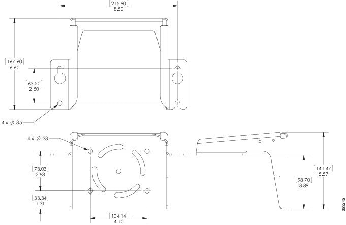
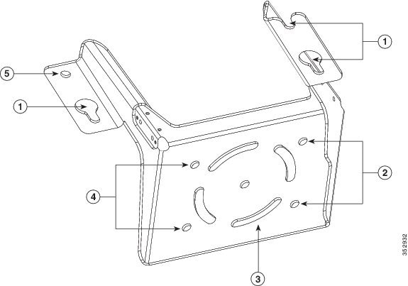
Figure 3-30 PMK3 Wall Mounting Bracket for Mounting AP Horizontally
Pole Mounting Using PMK3
You can use PMK3 for horizontally mounting the AP on vertical poles, horizontal poles, and on off-angle poles of diameter ranging from 2 to 16 inches. For more information about PMK3, see Pole Mount Kit 3.
Table 3-7 Materials Needed to Mount the AP using PMK3
Two 0.75 inches (19 mm) stainless steel band straps (adjustable 2– 6 inches, 50–406 mm) |
|
To mount the AP using PMK3, follow these steps.
Step 1![]() Position the strap brackets on the pivot bracket according to the diameter of the pole. Secure each strap bracket with two M8 x16 bolts (with lock washers) and M8 nuts (Figure 3-21). Tighten the bolts to 13 to 15 lb.ft (17.6 to 20.3 Nm).
Position the strap brackets on the pivot bracket according to the diameter of the pole. Secure each strap bracket with two M8 x16 bolts (with lock washers) and M8 nuts (Figure 3-21). Tighten the bolts to 13 to 15 lb.ft (17.6 to 20.3 Nm).
Step 2![]() Select a mounting location on the pole to mount the access point.
Select a mounting location on the pole to mount the access point.
–![]() For vertical poles, position the strap and pivot brackets assembly as shown in Figure 3-32. The pivot bracket is oriented vertically.
For vertical poles, position the strap and pivot brackets assembly as shown in Figure 3-32. The pivot bracket is oriented vertically.
–![]() For horizontal poles, position the strap and pivot brackets assembly as shown in Figure 3-33. The pivot bracket is oriented horizontally.
For horizontal poles, position the strap and pivot brackets assembly as shown in Figure 3-33. The pivot bracket is oriented horizontally.
Note![]() If you will be using a streetlight power tap adapter, position the access point within 3 ft (1 m) of the outdoor light control
If you will be using a streetlight power tap adapter, position the access point within 3 ft (1 m) of the outdoor light control
Step 3![]() Mount the strap and pivot brackets assembly at the mounting location on the pole, using the two band straps, as follows:
Mount the strap and pivot brackets assembly at the mounting location on the pole, using the two band straps, as follows:
–![]() For pole diameters more than 3.5 inch (89 mm), loop each metal band strap twice through the slots on the strap brackets (see Figure 3-22). Follow the instructions provided with the band strap tool (BAND IT) (AIR-BAND-INST-TL=).
For pole diameters more than 3.5 inch (89 mm), loop each metal band strap twice through the slots on the strap brackets (see Figure 3-22). Follow the instructions provided with the band strap tool (BAND IT) (AIR-BAND-INST-TL=).
–![]() For pole diameters equal to or less than 3.5 inch (89 mm), loop each metal band strap twice through the slots on the strap brackets and also through the narrow space between the pole clamp bracket and the strap brackets (see Figure 3-22). This ensures maximum holding strength, especially for extreme environments. Following the instructions provided with the band strap tool (BAND IT) (AIR-BAND-INST-TL=).
For pole diameters equal to or less than 3.5 inch (89 mm), loop each metal band strap twice through the slots on the strap brackets and also through the narrow space between the pole clamp bracket and the strap brackets (see Figure 3-22). This ensures maximum holding strength, especially for extreme environments. Following the instructions provided with the band strap tool (BAND IT) (AIR-BAND-INST-TL=).
Step 4![]() Tighten the metal band straps using the banding strap tool (BAND IT) (Cisco AIR-BAND-INST-TL=) by following the operating instructions in the box with the tool. Ensure that the metal band straps are as tight as possible.
Tighten the metal band straps using the banding strap tool (BAND IT) (Cisco AIR-BAND-INST-TL=) by following the operating instructions in the box with the tool. Ensure that the metal band straps are as tight as possible.
Step 5![]() Hold the PMK3 horizontal wall mount bracket against the pivot bracket such that the curved slots and the bolt holes line up.
Hold the PMK3 horizontal wall mount bracket against the pivot bracket such that the curved slots and the bolt holes line up.
Step 6![]() Insert and hand-tighten four M8 x16 bolts (with flat and lock washers) into the bolt holes. Do not over tighten.
Insert and hand-tighten four M8 x16 bolts (with flat and lock washers) into the bolt holes. Do not over tighten.
Step 7![]() For off-angle poles, you can now rotate the mounting bracket as required. Rotate to ensure that the AP will be oriented vertically and that the LEDs on the base of the AP will be visible from the ground.
For off-angle poles, you can now rotate the mounting bracket as required. Rotate to ensure that the AP will be oriented vertically and that the LEDs on the base of the AP will be visible from the ground.
Note![]() The horizontal wall mount bracket can be rotated to up to 45o from the vertical, while attached to the pivot bracket. This allows you to compensate for the tilt of off-angle poles, such as tilted streetlight arms.
The horizontal wall mount bracket can be rotated to up to 45o from the vertical, while attached to the pivot bracket. This allows you to compensate for the tilt of off-angle poles, such as tilted streetlight arms.
Step 8![]() Make final adjustments, if needed, to the top edge of the horizontal wall mount bracket so that it is horizontal. Ensure such that the AP will be oriented vertically and that the LEDs on the base of the AP will be visible from the ground. Then tighten the bolts four bolts to 13 to 15 lb.ft (17.6 to 20.3 Nm).
Make final adjustments, if needed, to the top edge of the horizontal wall mount bracket so that it is horizontal. Ensure such that the AP will be oriented vertically and that the LEDs on the base of the AP will be visible from the ground. Then tighten the bolts four bolts to 13 to 15 lb.ft (17.6 to 20.3 Nm).
Step 9![]() Screw M8 bolts into three of the four bolt holes on the back side of the access point (Screw holes 1, 4, and 5 in Figure 3-31)
Screw M8 bolts into three of the four bolt holes on the back side of the access point (Screw holes 1, 4, and 5 in Figure 3-31)
Do not screw in the bolts all the way. Leave a gap of about 0.13 inch (3.3 mm).
Step 10![]() Position the three bolts on the access point into the wall mount bracket’s keyhole slots. Check to ensure that the access point is properly seated in the slots. (see Figure 3-34)
Position the three bolts on the access point into the wall mount bracket’s keyhole slots. Check to ensure that the access point is properly seated in the slots. (see Figure 3-34)
Step 11![]() Screw in the fourth M8 x 12mm hex head bolt into the non-keyhole type screw hole (Screw hole 6 in Figure 3-31).
Screw in the fourth M8 x 12mm hex head bolt into the non-keyhole type screw hole (Screw hole 6 in Figure 3-31).
Using a 13 mm open-end or socket wrench, tighten all four M8 x 12mm hex head bolts to a torque of 13 to 15 lb.ft (17.6 to 20.3 Nm).
Step 12![]() Continue with installing antennas, connecting the data cables, grounding the access point, and powering the access point. For information on these, see Chapter4, “Installing Other Components”
Continue with installing antennas, connecting the data cables, grounding the access point, and powering the access point. For information on these, see Chapter4, “Installing Other Components”
Figure 3-31 Keyhole type Screw Holes and the Non-keyhole type Screw Hole
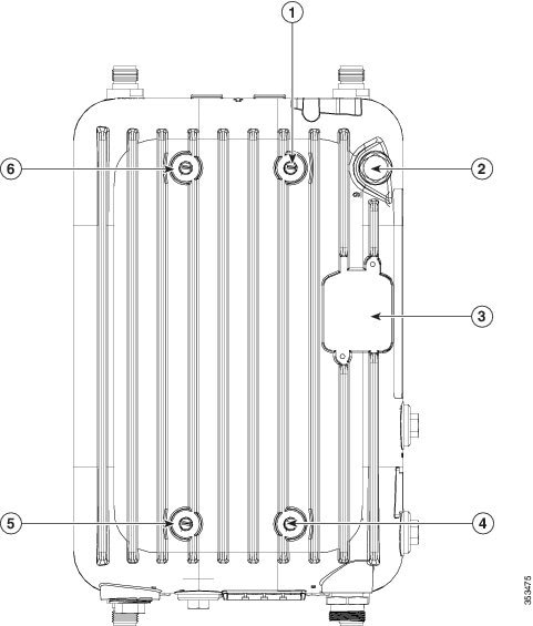
Figure 3-32 Wall Bracket Attached to Strap Bracket-Pivot Bracket Assembly for Vertical Pole
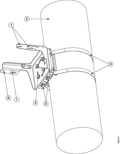
Figure 3-33 Wall Bracket attached to Strap Bracket-Pivot Bracket Assembly for Horizontal Pole
|
|
|
M8x16mm bolts used to attach the strap brackets to the pivot bracket. The strap brackets are set for pole of 6 to 11 inches diameter, and the pivot bracket is in horizontal orientation. |
|
|
|
|
Figure 3-34 AP1572I Horizontally Mounted on Horizontal Pole using PMK3 Kit
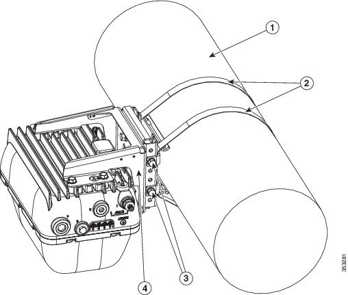
|
|
|
||
|
|
M8x16mm bolts used to attach the strap brackets to the pivot bracket. The strap brackets are set for pole of 6 to 11 inches diameter, and the pivot bracket is in horizontal orientation. |
|
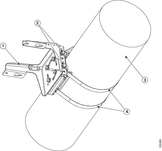
Figure 3-35 AP1572I Horizontally Mounted on Vertical Pole using PMK3 Kit
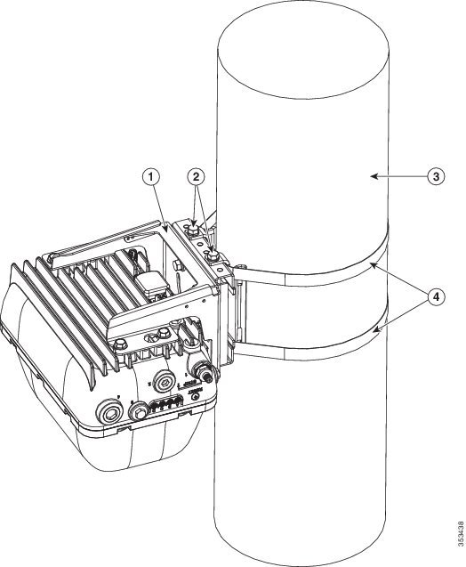
|
|
|
M8x16mm bolts used to attach the strap brackets to the pivot bracket. The strap brackets are set for pole of 6 to 11 inches diameter, and the pivot bracket is in horizontal orientation. |
|
|
|
|
Wall Mounting Using PMK3
To horizontally mount the AP on a wall, you can use PMK3 without the pivot bracket and the strap brackets. Using only the PMK3 wall mount bracket, you can horizontally mount the AP on a wall. For more information about PMK3, see Pole Mount Kit 3.
Table 3-8 Materials Needed to Mount the AP on a Wall using PMK2
(22.7 kg) static weight, and should conform to all local codes and regulations.
To mount the access point on a vertical wall, follow these instructions:
Step 1![]() Use the wall mount bracket as a template to mark four screw hole locations on your mounting surface.
Use the wall mount bracket as a template to mark four screw hole locations on your mounting surface.
The recommended screw hole locations are shown in Figure 3-30.
The dimensions of the PMK3 wall mount bracket is shown in Figure 3-29.
Step 2![]() Using four screws and optional screw anchors, attach the wall mount bracket to the wall. Ensure that the four screws are fully tightened.
Using four screws and optional screw anchors, attach the wall mount bracket to the wall. Ensure that the four screws are fully tightened.
Note![]() If necessary, use suitable screw anchors and an exterior-grade plywood backboard to mount the access point to stucco, cement, or drywall.
If necessary, use suitable screw anchors and an exterior-grade plywood backboard to mount the access point to stucco, cement, or drywall.
Step 3![]() Screw M8 bolts into three of the four bolt holes on the back side of the access point (Screw holes 1, 4, and 5 in Figure 3-31).
Screw M8 bolts into three of the four bolt holes on the back side of the access point (Screw holes 1, 4, and 5 in Figure 3-31).
Do not screw in the bolts all the way. Leave a gap of about 0.13 inch (3.3 mm).
Step 4![]() Position the three bolts on the access point into the wall mount bracket’s keyhole slots. Check to ensure that the access point is properly seated in the slots. (see Figure 3-34)
Position the three bolts on the access point into the wall mount bracket’s keyhole slots. Check to ensure that the access point is properly seated in the slots. (see Figure 3-34)
Step 5![]() Screw in the fourth M8 x 12mm hex head bolt into the non-keyhole type screw hole (Screw hole 6 in Figure 3-31).
Screw in the fourth M8 x 12mm hex head bolt into the non-keyhole type screw hole (Screw hole 6 in Figure 3-31).
Using a 13 mm open-end or socket wrench, tighten all four M8 x 12mm hex head bolts to a torque of 13 to 15 lb.ft (17.6 to 20.3 Nm).
Step 6![]() Continue with installing antennas, connecting the data cables, grounding the access point, and powering the access point. For information on these, see Chapter4, “Installing Other Components”
Continue with installing antennas, connecting the data cables, grounding the access point, and powering the access point. For information on these, see Chapter4, “Installing Other Components”
 Feedback