- Preface
- Product Overview
- Preparing for Installation
- Mounting the Access Point
- Installing Other Components
- Troubleshooting
- Appendix A - Access Point Tech Specs References
- Appendix B - Declarations of Conformity and Regulatory Information
- Appendix C - Access Point Pinouts
- Appendix D - Configuring DHCP Option 43
- Power-over-Cable
- AC Power Supply
- DC Interface
- PoE-Input
- Restrictions on Features under Different Operating Conditions
- Connecting a Power Injector
- Connecting an Ethernet Cable to the Access Point
- Connecting a DC Power Cable to the Access Point
- Connecting Streetlight AC Power
- Connecting an AC Power Cable to the Access Point
- Connecting PoC Power to the Access Point
Installing Other Components
This chapter contains information on AP accessories and instructions on installing antennas, grounding the AP, and powering the AP. It contains the following sections:
Supported Antennas
All versions of 1570 series access points have 4x4:3 2.4 GHz radios and 4x4:3 5 GHz radios.
AP1572I Internal Antennas
AP1572I has four internal dual band antennas. The maximum 2.4 GHz gain is 4 dBi. The maximum 5 GHz gain is 6 dBi.
AP1572E External Antennas
AP1572E has four dual band antenna ports, to which external antennas can be mounted to or connected to, as specified in Table 4-1.

Note![]() When operating in the 5GHz UNII-1 band, all Omni Directional antennas should be installed vertically, and all directional antennas should be installed with the main beam aimed parallel to or tilted down toward the horizon.
When operating in the 5GHz UNII-1 band, all Omni Directional antennas should be installed vertically, and all directional antennas should be installed with the main beam aimed parallel to or tilted down toward the horizon.
Table 4-1 Supported External Antennas for AP1572E
Non-Cisco Antennas
Cisco does not support any third-party antennas. RF connectivity and compliance of third party antennas is the customer’s responsibility. Cisco does not recommend any third-party antennas, and Cisco Technical Assistance Center will not be able to provide any support for third-party antennas. Cisco’s FCC Part 15 compliance is only guaranteed with Cisco antennas or antennas that are of the same design and gain as Cisco antennas.
Antenna Configurations
All versions of the 1570 series access points contain a 4x4:3 2.4 GHz radio and a 4x4:3 5 GHz radio, which are connected to physical antennas/antenna ports numbered 1, 2, 3, and 4. These radios can be configured for both dual-band (both 2.4 GHz and 5 GHz signals coming from the same antenna ports) and single band (2.4 GHz and 5 GHz signals coming from different antennas / antenna ports). The 2.4 and 5 GHz radios connected to these antennas/antenna ports are user configurable as follows:
- The maximum number of active Tx/Rx antennas/antenna ports paths for both the 2.4 and 5 GHz 4x4 radios is restricted to the modes of operation set forth in Section 3.2.7.
- The allowable configurations for the 5 GHz radio are:
- The allowable configurations for the 2.4 GHz radio are:
|
|
|
|||
|---|---|---|---|---|
|
|
|
|
|
|
|
|
|
|||
|---|---|---|---|---|
|
|
|
|
|
|
Installing External Antennas
Note![]() Before connecting power to the access point, ensure that the antennas are attached to the access point
Before connecting power to the access point, ensure that the antennas are attached to the access point
See the section “Supported Antennas” section for details of the antennas supported by the 1572 series access points.
For installation instructions and detailed information on an antenna, refer to that particular antenna’s document located at:
http://www.cisco.com/c/en/us/support/wireless/aironet-antennas-accessories/products-installation-guides-list.html
Follow all safety precautions when installing the antennas. For information on safety, refer to “Safety Precautions when Installing Antennas” section.
Note![]() Omnidirectional antennas are vertically polarized and should be mounted vertically.
Omnidirectional antennas are vertically polarized and should be mounted vertically.
Note![]() When operating in the 5GHz UNII-1 band, all Omni Directional antennas should be installed vertically, and all directional antennas should be installed with the main beam aimed parallel to or tilted down toward the horizon.
When operating in the 5GHz UNII-1 band, all Omni Directional antennas should be installed vertically, and all directional antennas should be installed with the main beam aimed parallel to or tilted down toward the horizon.
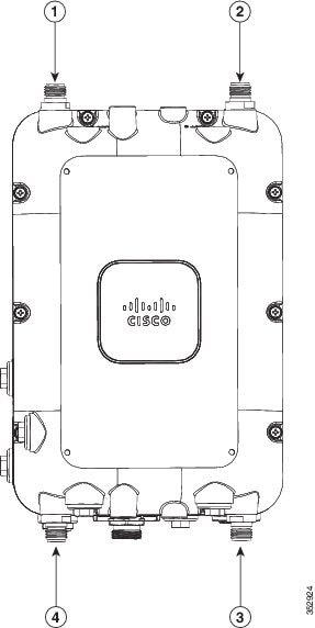
Antenna N-Type Connector Locations
The AP1572E access point version has two N-type antenna connectors located on the base and two N-type antenna connectors on the head of the access point. The N-type connectors support variety of the Cisco Aironet antennas. For detailed information on these antennas, refer to Antenna Configurations, in chapter 1.
Figure 4-1 shows the antenna port locations on the AP.
Figure 4-1 Antenna Port Locations - AP Face View
|
|
|
||
|
|
|
External Antenna Mounting Configurations
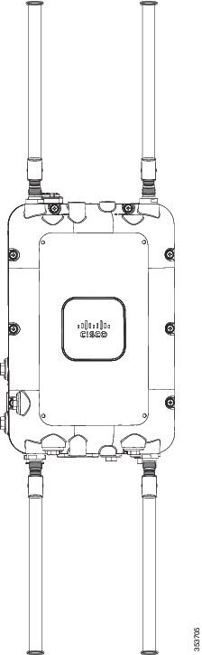
Omni Antennas
Omni antennas can be mounted directly to the access point (see Figure 4-2). The supported omni antennas are:
- AIR-ANT2547V-N
- AIR-ANT2547VG-N
- AIR-ANT2568VG-N
- AIR-ANT2440V-N
- AIR-ANT2450V-N
- AIR-ANT2480V-N
- AIR-ANT5140V-N
- AIR-ANT5180V-N
The AP should always be operated with four omni antennas attached for best performance. If you decide to use less than four antennas, ensure that the unused antenna ports are properly covered with an appropriate N-male connector cap (Cisco provides a kit of 10 such caps in AIR-ACC15-N-CAP=).
Figure 4-2 AIR-CAP1572EAC-x-K9 with AIR-ANT2547VG-N
AIR-ANT2513P4M-N=
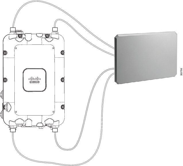
The AP1572 can be used with a directional antenna that connects via cables (either directly attached to the antenna or with separate cables). See Figure 4-3.
AIR-ANT2513P4M-N= comes with its own mounting kit that will allow it to be mounted to the same pole or wall where the AP1572 is also mounted. Four N-male to N-male cables (such as AIR-CAB005LL-N=) are required to connect the antenna to the AP.
Figure 4-3 AIR-CAP1572EAC-x-K9 with AIR-ANT2513P4M-N=
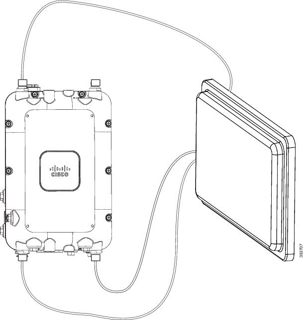
AIR-ANT2588P3M-N=
The AIR-ANT2588P3M-N= comes with its own mounting kit which allows it to be mounted to the same pole or wall where the AP1572 is mounted. Three N-male to N-male cables (such as AIR-CAB005LL-N=) are required to connect the antenna to the AP. Connect the cables to Ports 1,2, and 3 and install an N-male cap on Port 4. See Figure 4-4.
Figure 4-4 AIR-CAP1572EAC-x-K9 with AIR-ANT2588P3M-N=
AIR-ANT2413P2M-N= and AIR-ANT5114P2M-N=
The AIR-ANT2413P2M-N= and AIR-ANT5114P2M-N= antennas come with their own mounting kits which will allow them to be mounted on the same pole or wall where the AP1572 is mounted. These antennas come with two attached cables to connect directly to the AP. The AP should be placed in single band antenna mode and AIR-ANT2413P2M-N= should be connected to Antenna Ports 1 and 2, and AIR-ANT5114P2M-N= should be connected to Antenna Ports 3 and 4 on the AP. See Figure 4-5
Using an optional antenna mounting bracket kit, the directional antennas AIR-ANT2413P2M-N and AIR-ANT5114P2M-N can also be mounted directly on the AP1572EC access point in a strand mount or pole mount environment. The antenna bracket kit contains four bracket sections and fasteners that you can assemble in multiple configurations to position and aim the directional antenna in a range of positions. For more information on mounting the antenna with the optional mounting bracket, refer to Installing Directional-Antenna Mounting Kits on Cisco 1550 Series Outdoor Mesh Access Points, at the following URL:
http://www.cisco.com/c/en/us/td/docs/wireless/access_point/1550/quick/guide/1550antbracket.html
Figure 4-5 AIR-CAP1572EAC-x-K9 with AIR-ANT2413P2M-N= and AIR-ANT5114P2M-N=
Weatherproofing the Type N Connector Joint
Note![]() The following is a general procedure for weatherproofing a Type N connector joint.
The following is a general procedure for weatherproofing a Type N connector joint.
Step 1![]() Ensure that the type N connectors are clean and dry.
Ensure that the type N connectors are clean and dry.
Step 2![]() Apply the oxide inhibitor paste with a Q-tip to each connector pin and the receptacle interiors of both the connectors. This ensures an airtight and watertight seal between the connectors.
Apply the oxide inhibitor paste with a Q-tip to each connector pin and the receptacle interiors of both the connectors. This ensures an airtight and watertight seal between the connectors.
Step 3![]() Fasten the antenna cable’s N-type male connector to the access point’s N-type male connector and tighten as directed in the antenna guide.
Fasten the antenna cable’s N-type male connector to the access point’s N-type male connector and tighten as directed in the antenna guide.
Step 4![]() Wipe away any excess oxide inhibitor paste.
Wipe away any excess oxide inhibitor paste.
Step 5![]() Tightly wrap the fastened connectors with two layers of electrical tape, such that the wrapping extends 1 inch past each end of the connection.
Tightly wrap the fastened connectors with two layers of electrical tape, such that the wrapping extends 1 inch past each end of the connection.
Step 6![]() Tightly wrap the electrical tape layers with two layers of butyl mastic tape, such that the wrapping extends 1 inch past each end of the electrical tape wrapping.
Tightly wrap the electrical tape layers with two layers of butyl mastic tape, such that the wrapping extends 1 inch past each end of the electrical tape wrapping.
Your RF connection can now stay clean and dry for a long time.
Detailed Documentation for all Supported External Antennas
For detailed information on supported antennas, refer the following links:
http://www.cisco.com/c/en/us/td/docs/wireless/antenna/installation/guide/ant2568vgn.html
http://www.cisco.com/c/en/us/td/docs/wireless/antenna/installation/guide/ant2547vgn.html
http://www.cisco.com/c/en/us/td/docs/wireless/antenna/installation/guide/ant2588p3m-n.html
http://www.cisco.com/c/en/us/td/docs/wireless/antenna/installation/guide/ant2513p4mn.html
http://www.cisco.com/c/en/us/td/docs/wireless/antenna/installation/guide/ant2450v.html
http://www.cisco.com/c/en/us/td/docs/wireless/antenna/installation/guide/ant2480v.html
http://www.cisco.com/c/en/us/td/docs/wireless/antenna/installation/guide/ant2413p2m-n.html
http://www.cisco.com/c/en/us/td/docs/wireless/antenna/installation/guide/ant5140v.html
http://www.cisco.com/c/en/us/td/docs/wireless/antenna/installation/guide/ant5180v.html
http://www.cisco.com/c/en/us/td/docs/wireless/antenna/installation/guide/ant5114p2m-n.html
http://www.cisco.com/c/en/us/td/docs/wireless/antenna/installation/guide/ant5114P.html
Installing a Lightning Arrestor
Overvoltage transients can be created through lightning static discharges, switch processes, direct contact with power lines, or through earth currents. The Cisco Aironet AIR-ACC245LA-N Lightning Arrestor limits the amplitude and duration of disturbing interference voltages and improves the over voltage resistance of in-line equipment, systems, and components. A lightning arrestor installed according to these mounting instructions balances the voltage potential, thus preventing inductive interference to parallel signal lines within the protected system.
Installation Considerations
Cisco recommends that you bulkhead mount the lightning arrestor so it can be installed as a wall-feed through on the wall of the protected space.
The importance of obtaining a good ground and bonding connection cannot be overstressed. Consider these points when grounding the lightning arrestor:
Installation Notes
This lightning arrestor is designed to be installed between the antenna cable that is attached to an outdoor antenna and the Cisco Aironet wireless device. You can install the lightning arrestor either indoors or outdoors. It can be connected directly to a wireless device having an external N connector. It can also be mounted inline or as a feed-through. Feed-through installations require 5/8 in. (16 mm) hole to accommodate the lightning arrestor.
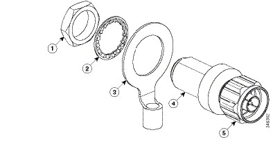
Note![]() This lightning arrestor is part of a lightning arrestor kit. The kit contains a lightning arrestor and a grounding lug.
This lightning arrestor is part of a lightning arrestor kit. The kit contains a lightning arrestor and a grounding lug.
Note![]() When you install the lightning arrestor, follow the regulations or best practices applicable to lightning protection installation in your local area.
When you install the lightning arrestor, follow the regulations or best practices applicable to lightning protection installation in your local area.
Installing the Lightning Arrestor Outdoors
If you install the lightning arrestor outdoors, use the supplied ground lug and a heavy wire (#6 solid copper) to connect it to a good earth ground, such as a ground rod. The connection should be as short as possible.
Figure 4-6 Lightning Arrestor Details
|
|
|
||
|
|
|
||
|
|
|||
Cable for the Lightning Arrestor
Coaxial cable loses efficiency as the frequency increases, resulting in signal loss. The cable should be kept as short as possible because cable length also determines the amount of signal loss (the longer the run, the greater the loss).
Cisco recommends a high-quality, low-loss cable for use with the lightning arrestor.
Grounding the Access Point
The access point must be grounded before connecting power.

Warning![]() This equipment must be externally grounded using a customer-supplied ground wire before power is applied. Contact the appropriate electrical inspection authority or an electrician if you are uncertain that suitable grounding is available. Statement 366
This equipment must be externally grounded using a customer-supplied ground wire before power is applied. Contact the appropriate electrical inspection authority or an electrician if you are uncertain that suitable grounding is available. Statement 366
In all outdoor installations, you must follow these instructions to properly ground the case:
Step 1![]() If using insulated 6-AWG copper ground wire, strip the insulation as required for the grounding lug.
If using insulated 6-AWG copper ground wire, strip the insulation as required for the grounding lug.
Step 2![]() Use the appropriate crimping tool to crimp the bare 6-AWG copper ground wire to the supplied grounding lug.
Use the appropriate crimping tool to crimp the bare 6-AWG copper ground wire to the supplied grounding lug.
Note![]() The grounding lug and hardware used must comply with local and national electrical codes.
The grounding lug and hardware used must comply with local and national electrical codes.
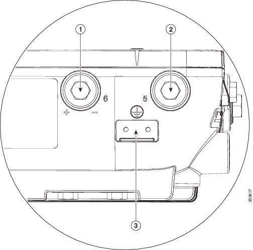
Step 3![]() Open the anti-corrosion sealant (supplied), and apply a liberal amount over the metal surface where the ground strap screw holes are located (see Figure 4-7 below).
Open the anti-corrosion sealant (supplied), and apply a liberal amount over the metal surface where the ground strap screw holes are located (see Figure 4-7 below).
Figure 4-7 Ground Strap Screw Holes Located on the Right Side of the AP
|
|
|
Metal plate with screw holes for attaching the grounding lug |
|
|
|
|
Step 4![]() Connect the grounding lug to the access point grounding screw holes using the supplied two Phillips head screws (M4 x10 mm) with lock washers. Tighten the grounding screw to 22 to 24 lb-in (2.49 to 2.71 Nm).
Connect the grounding lug to the access point grounding screw holes using the supplied two Phillips head screws (M4 x10 mm) with lock washers. Tighten the grounding screw to 22 to 24 lb-in (2.49 to 2.71 Nm).
Step 5![]() Connect the other end of the ground wire to a reliable earth ground, such as a grounding rod or an appropriate grounding point on a metal streetlight pole that is grounded.
Connect the other end of the ground wire to a reliable earth ground, such as a grounding rod or an appropriate grounding point on a metal streetlight pole that is grounded.
Connecting a Fiber-optic Cable to the AP
The Cisco supplied fiber-optic kit enables the access point to support fiber-optic network connections.
Your require the following materials for connecting the fiber-optic cable to the AP:
- Small form-factor pluggable (SFP) transceiver module
- SFP module adapter
- SC or Duplex LC fiber-optic cables. The outer diameter of the fiber optic cable should be 0.24-0.47 inches (6-12 mm).
- Cable gland. The cable gland cannot hold a cable with diameter more than 0.47” (12 mm).
- Adjustable wrench
You can connect the fiber-optic networking cable to the SFP port (labeled '4' on the base of the AP). The small form-factor pluggable (SFP) transceiver module is used to connect the cable to the SFP port. The SFP port provides both Power-over-Cable and backhaul over fiber options. To install the SFP transceiver module and the cable, follow this procedure:
Step 1![]() Ensure that all power sources have been disconnected from the access point.
Ensure that all power sources have been disconnected from the access point.
Step 2![]() Remove the covering plug from the SFP port by following the guidelines given in this step.
Remove the covering plug from the SFP port by following the guidelines given in this step.
The SFP port covering plug is designed to be removed only once, and then be replaced with the SFP adapter. The plug does not have a rubber O-ring, but is fixed in place using a sealant on the threads at manufacturing. While removing the plug, you need to ensure that its hex bolt-head does not get stripped. For this:
a.![]() Place the AP on it's back (resting on the heat fins) on a solid, but padded surface, to avoid scratching the paint.
Place the AP on it's back (resting on the heat fins) on a solid, but padded surface, to avoid scratching the paint.
b.![]() Pressing down with your hand on the face of the AP and holding the AP firmly in place, proceed to the next step.
Pressing down with your hand on the face of the AP and holding the AP firmly in place, proceed to the next step.
c.![]() Use a 5/8” (16 mm) 6-point socket wrench to loosen the hex bolt-head SFP port plug. Firmly and carefully, turn the socket wrench counter-clockwise to loosen the plug. This requires a torque of 25 ft-lb (34 Nm).
Use a 5/8” (16 mm) 6-point socket wrench to loosen the hex bolt-head SFP port plug. Firmly and carefully, turn the socket wrench counter-clockwise to loosen the plug. This requires a torque of 25 ft-lb (34 Nm).
Though not ideal, a 5/8” (16 mm) 12-point socket wrench can be used too. A crescent wrench is to be used only if the socket wrenches are not available. Do not use a pipe or monkey wrench for this task, as it will strip the hex bolt-head.
Step 3![]() Insert the SFP module into the SFP port, and ensure that it latches properly.
Insert the SFP module into the SFP port, and ensure that it latches properly.
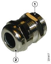
Step 4![]() Loosen the cable gland’s nut (round end of the cable gland) by turning counterclockwise, but do not remove.
Loosen the cable gland’s nut (round end of the cable gland) by turning counterclockwise, but do not remove.
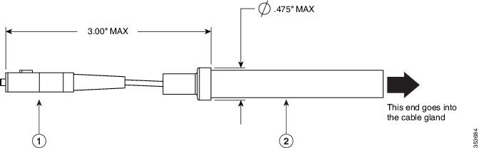
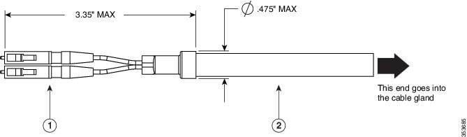
Step 5![]() Thread the fiber optic cable, from its unterminated end, into the cable gland. See Figure 4-8 and Figure 4-9.
Thread the fiber optic cable, from its unterminated end, into the cable gland. See Figure 4-8 and Figure 4-9.
Thread the cable through the gland all the way till the gland is near the SC or LC optic fiber connectors. The cable gland’s nut must remain loose at this time.
Note![]() The SC or LC optic fiber connectors are too big to pass through the cable gland. That is the reason why you need to thread the cable through the gland from the unterminated end (even if the cable is quite long).
The SC or LC optic fiber connectors are too big to pass through the cable gland. That is the reason why you need to thread the cable through the gland from the unterminated end (even if the cable is quite long).
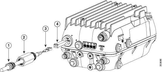
Step 6![]() Insert the SC or LC optic fiber connector-end of the cable, into the SFP module adapter. Do not attach the cable gland to the adapter yet. See Figure 4-10.
Insert the SC or LC optic fiber connector-end of the cable, into the SFP module adapter. Do not attach the cable gland to the adapter yet. See Figure 4-10.
Step 7![]() Insert the SC or LC optic fiber connector into the SFP module and ensure that it latches into place. See Figure 4-10.
Insert the SC or LC optic fiber connector into the SFP module and ensure that it latches into place. See Figure 4-10.
Step 8![]() Add sealant or tape around the adapter's pipe thread, and then it screw into the AP chassis.
Add sealant or tape around the adapter's pipe thread, and then it screw into the AP chassis.
Step 9![]() Keeping the cable gland nut loose, carefully screw the threaded end of the cable gland into the SFP module adapter and hand-tighten. Use an adjustable wrench to tighten the threaded end of the cable gland to 6-7 lb.ft (8.1 to 9.5 Nm).
Keeping the cable gland nut loose, carefully screw the threaded end of the cable gland into the SFP module adapter and hand-tighten. Use an adjustable wrench to tighten the threaded end of the cable gland to 6-7 lb.ft (8.1 to 9.5 Nm).
Step 10![]() Tighten the cable gland nut until it is properly fastened around the fiber optic cable. Use an adjustable or open-end wrench to tighten to 2.7 to 3.2 lb.ft (3.66 to 4.34 Nm).
Tighten the cable gland nut until it is properly fastened around the fiber optic cable. Use an adjustable or open-end wrench to tighten to 2.7 to 3.2 lb.ft (3.66 to 4.34 Nm).

Figure 4-8 SC Fiber-optic cable
|
|
|
Figure 4-9 Duplex LC Fiber Optic Cable
|
|
|
Figure 4-10 Exploded View of Connecting Fiber-optic Cable to AP
|
|
|
||
|
|
|
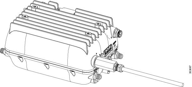
Figure 4-11 Fiber-optic Cable Successfully Connected to AP
Powering the Access Point
The external antenna versions (AP1572E versions) support power over Ethernet input (on the AC version only), power over Ethernet output supporting up to 802.3at devices, internal AC or power over cable power supply options.
If multiple power sources are available, the access point will select the power source which is higher on the following prioritization list. If a power source is removed, access point will automatically switch to the next available power source, as per this list:
1.![]() Power-over-cable or AC (whichever is available on your AP)
Power-over-cable or AC (whichever is available on your AP)
3.![]() PoE (available in AC powered versions of AP)
PoE (available in AC powered versions of AP)
Power-over-Cable
All versions of AP1572I and some versions of AP1572E are equipped with a power-over-cable (PoC) power supply. The power supply can accept quasi-AC signals in the 40 to 90 V RMS range.
Versions of the AP that have a PoC power supply, also have a shunt/fuse interface providing direct in-line access to the PoC AC signal. The AP comes with a shunt in the shunt/fuse location. By removing the shunt or fuse, field technicians can immediately remove power to the AP for service and repairs, and then restore power by re-installing the shunt or fuse. You can install a fuse in the shunt/fuse location to limit the maximum sustained current supplied to the AP to prevent damage to the AP or to the cable plant. Fuses of various amperage are available, and so you can select the appropriate fuse rating depending on the configuration and operating voltage.
For connecting a PoC power supply to the access point, see Connecting PoC Power to the Access Point.
AC Power Supply
Non PoC versions of the AP come equipped with an AC power supply. The power supply is designed to accept AC voltage from 100 V to 277 V RMS.
The following AC power cords are supported:
|
|
|
|---|---|
For connecting Streetlight AC power to the access point, see Connecting Streetlight AC Power.
For connecting an AC power supply to the access point, see Connecting an AC Power Cable to the Access Point.
DC Interface
All versions of the AP have an externally accessible DC input connector. The DC input accepts voltages in the 10 to 16V range. To check the power distribution budget, see https://www.cisco.com/c/en/us/td/docs/wireless/access_point/1570/installation/guide/1570hig/1570_axa.html.
For connecting a DC power supply to the access point, see Connecting a DC Power Cable to the Access Point.
PoE-Input
AC powered versions of AP1572EAC can be powered by UPOE compliant power sourcing equipment.
In addition to being powered by UPOE sources, the access point can also be powered by the AIR-PWRINJ1500-2 power injector.
The access point also supports an Ethernet uplink port (PoE-In). The access point Ethernet uplink port uses an RJ-45 connector (with weatherproofing) to link the access point to the 10BASE-T, 100BASE-T or 1000BASE-T network. The Ethernet cable is used to send and receive Ethernet data and to optionally supply inline power from the power injector or a suitably powered switch port.

Tip![]() The access point senses the Ethernet and power signals and automatically switches internal circuitry to match the cable connections.
The access point senses the Ethernet and power signals and automatically switches internal circuitry to match the cable connections.
The Ethernet cable must be a shielded outdoor rated Category 5e (CAT5e) or better cable. The access point senses the Ethernet and power signals and automatically switches internal circuitry to match the cable connections.
Depending on the version of the AP, a 1572 series access point supports these power sources:
The 1572EAC access point can be powered via the PoE input from an in-line power injector or a suitably powered switch port. The AIR-PWRINJ1500-2= power injector can be used.
Warning![]() Connect the unit only to DC power source that complies with the Safety Extra-Low Voltage (SELV) requirements in IEC 60950 based safety standards Statement 1033
Connect the unit only to DC power source that complies with the Safety Extra-Low Voltage (SELV) requirements in IEC 60950 based safety standards Statement 1033
For connecting the AIR-PWRINJ1500-2 power injector, see Connecting a Power Injector.
For connecting an Ethernet cable to the access point, see Connecting an Ethernet Cable to the Access Point
Restrictions on Features under Different Operating Conditions
To limit the maximum power consumption and ensure thermal integrity of the access point, there are factory-defined restrictions on the features that are active under a given operating condition. This is different for different versions of the AP.
The following restrictions are applicable to all versions under all operating conditions:
–![]() If an SFP device is detected on startup, the cable modem will be disabled and remain disabled until the AP is rebooted.
If an SFP device is detected on startup, the cable modem will be disabled and remain disabled until the AP is rebooted.
–![]() If no SFP device is detected on startup, the SFP port will be disabled and remain disabled until the AP is rebooted.
If no SFP device is detected on startup, the SFP port will be disabled and remain disabled until the AP is rebooted.
–![]() If no SFP device is detected at startup and the cable modem is connected, then the cable modem will be used as the uplink. The SFP will not be disabled. However, if an SFP device is plugged in later, the AP will require a reboot to choose the SFP port as the uplink.
If no SFP device is detected at startup and the cable modem is connected, then the cable modem will be used as the uplink. The SFP will not be disabled. However, if an SFP device is plugged in later, the AP will require a reboot to choose the SFP port as the uplink.
- You cannot disable any Ethernet ports.
- The power available on the PoE output port can be 802.3at, 802.3af, or disabled depending on other configuration options.
- PoE-Output is disabled when PoE-Input voltage is present.
- If the AP is powered by other means and then switches to UPOE, the AP will automatically reconfigure itself as required.
- The access point has protection mechanisms to prevent overheating by reducing certain functionalities, if internal temperatures exceed factory-defined limits. Protection measures include reducing the number of active transmit paths on one or more radios. The number of active transmit paths will return to the user’s selected configuration when the overheating condition subsides. However, if the protection measures do not sufficiently reduce the temperature, then the AP will ultimately power down, with the LEDs flashing yellow at flashes per second. When the overheating condition subsides, the AP will power up automatically.
The following tables show the maximum radio transmission paths for various versions of the AP depending on the kind of input power, cable modem status, and SFP port status.
Note![]() The AP supports all modes described in the following tables, in ambient temperatures of -40°C to +45°C in all supported orientations, with a solar loading of 753 Watts/m2. For details on the operating temperature ranges of the access point, see Access Point Operating Temperature Specifications.
The AP supports all modes described in the following tables, in ambient temperatures of -40°C to +45°C in all supported orientations, with a solar loading of 753 Watts/m2. For details on the operating temperature ranges of the access point, see Access Point Operating Temperature Specifications.
|
|
|
|
|
|---|---|---|---|
|
|
|
|
|
|
|---|---|---|---|---|
|
|
|
|
|
|---|---|---|---|
Connecting a Power Injector
The 1570 Series Access Points supports the AIR-PWRINJ1500-2= (100-240 VAC input, indoor use only) power injectors.The power injector provides (AIR-PWRINJ1500-2=) 56 VDC to the access point over the Ethernet cable and supports a total end-to-end Ethernet cable length of 100 m (328 ft) from the switch to the access point.
When your access point is powered by an optional power injector, follow these steps to complete the installation:
Step 1![]() Before applying PoE to the access point, ensure that the access point is grounded (see the “Grounding the Access Point” section).
Before applying PoE to the access point, ensure that the access point is grounded (see the “Grounding the Access Point” section).
Step 2![]() Review Figure 3-1 to identify the components needed for the installation.
Review Figure 3-1 to identify the components needed for the installation.
Note![]() The 1500 power injector can only be used in an indoor environment, therefore, the cable from the injector must travel from the protected location to the outside mounted access point.
The 1500 power injector can only be used in an indoor environment, therefore, the cable from the injector must travel from the protected location to the outside mounted access point.
Step 3![]() Connect a CAT5e or better Ethernet cable from your wired LAN network to the power injector.
Connect a CAT5e or better Ethernet cable from your wired LAN network to the power injector.
Warning![]() To reduce the risk of fire, use only No. 26 AWG or larger telecommunication line cord. Statement 1023
To reduce the risk of fire, use only No. 26 AWG or larger telecommunication line cord. Statement 1023
Note![]() The installer is responsible for ensuring that powering the access point from this type of power injector is allowed by local and/or national safety and telecommunications equipment standards.
The installer is responsible for ensuring that powering the access point from this type of power injector is allowed by local and/or national safety and telecommunications equipment standards.
Tip To forward bridge traffic, add a switch between the power injector and controller. Refer to the Cisco Wireless Mesh Access Points, Design and Deployment Guide, Release 7.0 for more information.
Step 4![]() Ensure that the antennas are connected and that a ground is attached to the access point before you apply power to the access point.
Ensure that the antennas are connected and that a ground is attached to the access point before you apply power to the access point.
Step 5![]() Connect a shielded outdoor-rated Ethernet (CAT5e or better) cable between the power injector and the PoE-in connector of the access point.
Connect a shielded outdoor-rated Ethernet (CAT5e or better) cable between the power injector and the PoE-in connector of the access point.
Step 6![]() Connect the Ethernet cable to the access point PoE-In port (see “Connecting an Ethernet Cable to the Access Point” section).
Connect the Ethernet cable to the access point PoE-In port (see “Connecting an Ethernet Cable to the Access Point” section).
Connecting an Ethernet Cable to the Access Point
You need to supply these tools and materials:
- Shielded outdoor-rated Ethernet (CAT5e or better) cable with 0.2 to 0.35 in. (0.51 to 0.89 cm) diameter
- RJ-45 connector and installation tool
- Adjustable Wrench or 0.875 inch open-end wrench
- 0.5 inch or 13 mm wrench
To connect the shielded Ethernet cable to the access point, follow these steps:
Step 1![]() Disconnect power to the power injector, and ensure all power sources to the access point are turned off.
Disconnect power to the power injector, and ensure all power sources to the access point are turned off.
Warning![]() This unit might have more than one power supply connection. All connections must be removed to de-energize the unit. Statement 1028
This unit might have more than one power supply connection. All connections must be removed to de-energize the unit. Statement 1028
Step 2![]() Ensure that access point is properly grounded as described in “Grounding the Access Point” section.
Ensure that access point is properly grounded as described in “Grounding the Access Point” section.
Step 3![]() Use a 0.5 inch or 13 mm wrench to remove the Ethernet connector cover plug which covers the Ethernet port labeled ‘3’ on the base of the access point. See Base of the AP for more information on where the port is located.
Use a 0.5 inch or 13 mm wrench to remove the Ethernet connector cover plug which covers the Ethernet port labeled ‘3’ on the base of the access point. See Base of the AP for more information on where the port is located.
Do not discard the plug and rubber seal unless you are certain that the port will not have to be re-plugged.
Step 4![]() Loosen the sealing nut of the cable gland, which is at its round end (see Figure 4-12), by turning it counter clockwise, but do not remove it.
Loosen the sealing nut of the cable gland, which is at its round end (see Figure 4-12), by turning it counter clockwise, but do not remove it.
Note![]() Verify that the cable gland has a rubber gasket and ensure that it is not damaged.
Verify that the cable gland has a rubber gasket and ensure that it is not damaged.
Warning![]() Failure to install the cable gland and rubber gasket properly will cause the cable grip to leak.
Failure to install the cable gland and rubber gasket properly will cause the cable grip to leak.
|
|
|
Step 5![]() Insert the unterminated end of the Ethernet cable through the sealing nut end of the cable gland (see Figure 4-12), and pull several inches of cable through the cable gland.
Insert the unterminated end of the Ethernet cable through the sealing nut end of the cable gland (see Figure 4-12), and pull several inches of cable through the cable gland.
Step 6![]() Install an RJ-45 connector on the unterminated end of the Ethernet cable using your Ethernet cable installation tool.
Install an RJ-45 connector on the unterminated end of the Ethernet cable using your Ethernet cable installation tool.
Warning![]() To reduce the risk of fire, use only No. 26 AWG or larger telecommunication line cord. Statement 1023
To reduce the risk of fire, use only No. 26 AWG or larger telecommunication line cord. Statement 1023
Warning![]() When installing the RJ-45 connector, ensure that cable gland and the rubber gasket are present and installed properly, to avoid water leakage into the enclosure. See Figure 4-12.
When installing the RJ-45 connector, ensure that cable gland and the rubber gasket are present and installed properly, to avoid water leakage into the enclosure. See Figure 4-12.
Step 7![]() Carefully insert the RJ-45 cable connector into the Ethernet port opening on the access point, and connect to the internal Ethernet connector.
Carefully insert the RJ-45 cable connector into the Ethernet port opening on the access point, and connect to the internal Ethernet connector.
Step 8![]() Slide the cable gland with the rubber gasket towards the access point, and screw the threaded end of the body into the access point, and hand-tighten.
Slide the cable gland with the rubber gasket towards the access point, and screw the threaded end of the body into the access point, and hand-tighten.
Step 9![]() Use an adjustable wrench or a 0.875 inch wrench to tighten the threaded end of the body into the enclosure. Tighten to 15 lb.ft.
Use an adjustable wrench or a 0.875 inch wrench to tighten the threaded end of the body into the enclosure. Tighten to 15 lb.ft.
Step 10![]() Use an adjustable wrench and tighten the thread-lock seal nut to 6 to 7 lb.ft (8.1 to 9.5 Nm).
Use an adjustable wrench and tighten the thread-lock seal nut to 6 to 7 lb.ft (8.1 to 9.5 Nm).
Step 11![]() Turn on power to the power injector.
Turn on power to the power injector.
Connecting a DC Power Cable to the Access Point
When powering the access point with DC power, you must ensure that DC power can be conveniently removed from the unit. The power should not be removed by disconnecting the DC power connector on the unit.
Warning![]() A readily accessible two-poled disconnect device must be incorporated in the fixed wiring.
A readily accessible two-poled disconnect device must be incorporated in the fixed wiring.
Statement 1022
Warning![]() Connect the unit only to DC power source that complies with the safety extra-low voltage (SELV) requirements in IEC 60950 based safety standards. Statement 1033
Connect the unit only to DC power source that complies with the safety extra-low voltage (SELV) requirements in IEC 60950 based safety standards. Statement 1033
To connect a DC power cable, you need these tools and material:
- Shielded outdoor-rated DC power cable (minimum 18 AWG) with outside cable diameter of 0.20 to 0.35 inch (0.51 to 0.89 cm).
- Adjustable wrench or 0.875 inch open-end wrench
- Small flat-head screw driver
- Two-pin DC terminal block connector (use only the Cisco supplied DC connector. Cisco Part Number 29-100226-01)
- 0.5 inch or 13mm wrench
To connect the DC power cable to the access point, follow these steps:
Step 1![]() Before connecting DC power to the access point, ensure that the ground is connected to the access point (see the “Grounding the Access Point” section).
Before connecting DC power to the access point, ensure that the ground is connected to the access point (see the “Grounding the Access Point” section).
Step 2![]() Turn off all power sources to the access point, including the DC power source.
Turn off all power sources to the access point, including the DC power source.
Warning![]() This unit might have more than one power supply connection. All connections must be removed to de-energize the unit. Statement 1028
This unit might have more than one power supply connection. All connections must be removed to de-energize the unit. Statement 1028
Step 3![]() Use a 0.5 inch or 13 mm wrench to remove the DC connector cover plug from the access point. The DC power port is located on the right side of the access point and is labeled ‘6’. See Right Side of the AP for more information on where the port is located.
Use a 0.5 inch or 13 mm wrench to remove the DC connector cover plug from the access point. The DC power port is located on the right side of the access point and is labeled ‘6’. See Right Side of the AP for more information on where the port is located.
Do not discard plug and rubber seal unless you are certain that the port will not have to be re-plugged.
Step 4![]() Loosen the thread-Lock sealing nut of the cable gland by turning it counter clockwise, but do not remove (see Figure 4-13).
Loosen the thread-Lock sealing nut of the cable gland by turning it counter clockwise, but do not remove (see Figure 4-13).
Note![]() Verify that the cable gland has a rubber gasket and ensure that it is not damaged.
Verify that the cable gland has a rubber gasket and ensure that it is not damaged.
Warning![]() Failure to install the cable gland and the rubber gasket properly will cause the cable grip to leak.
Failure to install the cable gland and the rubber gasket properly will cause the cable grip to leak.
|
|
|
Note![]() The cable gland can accept cables of diameter from 0.20 to 0.35 in. (0.51 to 0.89 cm).
The cable gland can accept cables of diameter from 0.20 to 0.35 in. (0.51 to 0.89 cm).
Step 5![]() Insert a bare end of the DC power cable into the rounded end of the cable gland (see Figure 4-13), and pull approximately 6 inches of cable through the adapter.
Insert a bare end of the DC power cable into the rounded end of the cable gland (see Figure 4-13), and pull approximately 6 inches of cable through the adapter.
Warning![]() When installing the DC power cable, ensure that cable gland and the rubber gasket are present and installed properly, to avoid water leakage into the enclosure.
When installing the DC power cable, ensure that cable gland and the rubber gasket are present and installed properly, to avoid water leakage into the enclosure.
Step 6![]() Strip the DC cable jacket back by about 1 inch to expose the wires and then strip the insulation by about 0.5 inch (or 12 mm) from each wire.
Strip the DC cable jacket back by about 1 inch to expose the wires and then strip the insulation by about 0.5 inch (or 12 mm) from each wire.
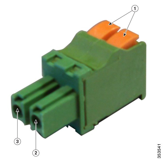
Step 7![]() Push in the orange colored spring-loaded securing tabs and insert the wire (see Figure 4-14) all the way into the two-position terminal block connector (Cisco Part Number 29-100226-01, Figure 4-15), and then release the tabs. Tug on the wire to ensure that it is properly secured.
Push in the orange colored spring-loaded securing tabs and insert the wire (see Figure 4-14) all the way into the two-position terminal block connector (Cisco Part Number 29-100226-01, Figure 4-15), and then release the tabs. Tug on the wire to ensure that it is properly secured.
Figure 4-14 Push in the securing tab, and wire, as the arrow shows
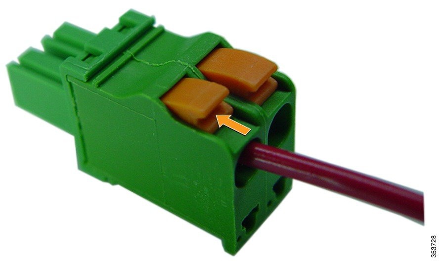
Figure 4-15 Two-Position Terminal Block Connector
|
|
|
||
|
|
|
Step 8![]() Insert the terminal block connector into the DC power opening in the access point case, and carefully push the terminal block connector into the internal connector.
Insert the terminal block connector into the DC power opening in the access point case, and carefully push the terminal block connector into the internal connector.
Note![]() Ensure that the polarity of the terminal block connector properly matches the polarity markings on the enclosure - see Figure 4-15. Use only the Cisco supplied block connector 29-100226-01.
Ensure that the polarity of the terminal block connector properly matches the polarity markings on the enclosure - see Figure 4-15. Use only the Cisco supplied block connector 29-100226-01.
Step 9![]() Slide the cable gland with the rubber seal towards the access point, and screw the threaded end of the body into the access point, and hand-tighten.
Slide the cable gland with the rubber seal towards the access point, and screw the threaded end of the body into the access point, and hand-tighten.
Step 10![]() Use an adjustable wrench or a 28 mm wrench to tighten the threaded end of the body to 15 lb.ft.
Use an adjustable wrench or a 28 mm wrench to tighten the threaded end of the body to 15 lb.ft.
Step 11![]() Use an adjustable wrench and tighten the thread-lock seal nut to 6 to 7 lb.ft (8.1 to 9.5 Nm).
Use an adjustable wrench and tighten the thread-lock seal nut to 6 to 7 lb.ft (8.1 to 9.5 Nm).
Step 12![]() Ensure that the antennas are connected to the access point before you apply power to the access point.
Ensure that the antennas are connected to the access point before you apply power to the access point.
Connecting Streetlight AC Power
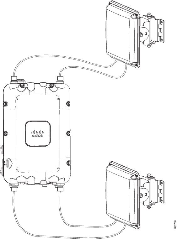
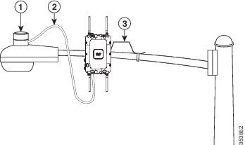
The access point can be installed on a streetlight pole and powered from a streetlight outdoor light control using the optional streetlight power tap adapter (AIR-PWR-ST-LT-R3P). See Figure 4-16.
100-to 277-VAC 50/60 Hz power. Do not connect to an outdoor light control powered by higher voltages.
When powering the access point with AC power other than the streetlight power tap adapter, you must ensure that the following conditions are observed:
1.![]() AC power can be conveniently removed from the unit. The power should not be removed by disconnecting the AC power connector on the unit.
AC power can be conveniently removed from the unit. The power should not be removed by disconnecting the AC power connector on the unit.
Warning![]() A readily accessible two-poled disconnect device must be incorporated in the fixed wiring.
A readily accessible two-poled disconnect device must be incorporated in the fixed wiring.
Statement 1022
2.![]() You must protect any AC power plugs and AC receptacles from water and other outdoor elements. You can use a UL-listed waterproofing enclosure suitable for covering the AC receptacle and AC power plug that supplies power to the unit as described in Article 406 of the NEC.
You must protect any AC power plugs and AC receptacles from water and other outdoor elements. You can use a UL-listed waterproofing enclosure suitable for covering the AC receptacle and AC power plug that supplies power to the unit as described in Article 406 of the NEC.
3.![]() When you install the access point outdoors or in a wet or damp location, the AC branch circuit that powers the access point should have ground fault protection (GFCI), as required by Article 210 of the National Electrical Code (NEC).
When you install the access point outdoors or in a wet or damp location, the AC branch circuit that powers the access point should have ground fault protection (GFCI), as required by Article 210 of the National Electrical Code (NEC).
Warning![]() Be very careful when connecting the streetlight adapter to Category 3 pole-top power. If you are not careful, you may electrocute yourself or fall. Statement 363
Be very careful when connecting the streetlight adapter to Category 3 pole-top power. If you are not careful, you may electrocute yourself or fall. Statement 363
To install an access point on a streetlight pole, follow these steps:
Step 1![]() Before beginning the installation, ensure the AC power to the streetlight pole is turned off.
Before beginning the installation, ensure the AC power to the streetlight pole is turned off.
Step 2![]() Turn off power to the AC power source at the designated circuits.
Turn off power to the AC power source at the designated circuits.
Warning![]() This unit might have more than one power supply connection. All connections must be removed to de-energize the unit. Statement 1028
This unit might have more than one power supply connection. All connections must be removed to de-energize the unit. Statement 1028
Step 3![]() When using the streetlight power tap adapter (AIR-PWR-ST-LT-R3P=), ensure that the access point is mounted within 3 feet (1 m) of the outdoor light control.
When using the streetlight power tap adapter (AIR-PWR-ST-LT-R3P=), ensure that the access point is mounted within 3 feet (1 m) of the outdoor light control.
Step 4![]() Ensure that a 6-AWG ground wire is attached to the access point and connected to the streetlight pole (for instructions see Grounding the Access Point).
Ensure that a 6-AWG ground wire is attached to the access point and connected to the streetlight pole (for instructions see Grounding the Access Point).
Step 5![]() Ensure that the streetlight power tap adapter, which uses a 3-pronged LC-10 twist-lock adapter, is placed between the outdoor light control and its fixture. The LC-10 twist-lock adapter is designed to be used with LC-10 listed outdoor light controls operating at 100 to 277 VAC, 50 to 60 Hz.
Ensure that the streetlight power tap adapter, which uses a 3-pronged LC-10 twist-lock adapter, is placed between the outdoor light control and its fixture. The LC-10 twist-lock adapter is designed to be used with LC-10 listed outdoor light controls operating at 100 to 277 VAC, 50 to 60 Hz.
Step 6![]() Disconnect the outdoor light control from its fixture.
Disconnect the outdoor light control from its fixture.
Step 7![]() Verify that the voltage available at the fixture is between 100 and 277 VAC, 50 to 60 Hz.
Verify that the voltage available at the fixture is between 100 and 277 VAC, 50 to 60 Hz.
Step 8![]() Turn off power to the fixture at the designated circuits.
Turn off power to the fixture at the designated circuits.
Note![]() Ensure that your antennas are connected to the access point before you apply power to the access point.
Ensure that your antennas are connected to the access point before you apply power to the access point.
Step 9![]() Connect the streetlight power tap adapter to the access point.
Connect the streetlight power tap adapter to the access point.
Step 10![]() Plug the streetlight power tap adapter into the outdoor light control fixture.
Plug the streetlight power tap adapter into the outdoor light control fixture.
Step 11![]() Plug the outdoor light control into the streetlight power tap adapter.
Plug the outdoor light control into the streetlight power tap adapter.
Step 12![]() Turn on the power to the outdoor light control fixture at the designated circuits.
Turn on the power to the outdoor light control fixture at the designated circuits.
Figure 4-16 Connecting Streetlight AC Power
|
|
|
||
|
|
|
Connecting an AC Power Cable to the Access Point
When powering the access point with AC power other than the streetlight power tap adapter, you must
ensure that the following conditions are observed:
- AC power can be conveniently removed from the unit. The power should not be removed by disconnecting the AC power connector on the unit.
Note![]() Before connecting or disconnecting a power cord, you must remove AC power from the power cord using a suitable service disconnect.
Before connecting or disconnecting a power cord, you must remove AC power from the power cord using a suitable service disconnect.
- You must protect all AC power plugs and AC receptacles from water and other outdoor elements. You can use a UL-listed waterproofing enclosure suitable for covering the AC receptacle and AC power plug that supplies power to the unit as described in Article 406 of the NEC.
- When you install the access point in a wet or damp location, the AC branch circuit that powers the access point should have ground fault protection (GFCI), as required by Article 210 of the National Electrical Code (NEC).
The AP1572EAC supports the following AC power cables and connectors available from Cisco:
|
|
|
|
|---|---|---|
This cord is for installations in the US and Canada, and comes with pre-installed connectors at both ends. The three prong plug is limited to 120 VAC. Internal wiring is rated at 600 VAC insulation protection. |
||
This cord for installations in the European Union. This cord comes with a pre-installed connector for connecting to the AP’s AC port. You will need to source and install a country-specific connector to the blunt cut end of the cable. For information on installing an AC power plug, see Installing AC Power Plug on AIR-CORD-R3P-40UE=. Power cord rating is 100 to 480 VAC. Internal wiring is 16 AWG. |
||
This is a kit of five field terminable connectors. For these connectors you will need to source an appropriate 3-wire AC cable. This connector supports a cable of 330 VAC, 13 Amps rating. The wiring size supported is 12 to 16 AWG. |
Installing AC Power Plug on AIR-CORD-R3P-40UE=
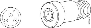
When using a user-supplied AC power plug on the AIR-CORD-R3P-40UE= power cord, ensure that the plug is certified for outdoor use and that it has a minimum IP67 rating, such as Interpower 84131251 or Hubbell HBL316P6W (IEC/EN 60309) pin-and-sleeve type connectors. The power cord plug pinouts are listed in Figure 4-17.
|
|
|
|
|
|
|
|---|---|---|---|---|---|
Procedure for Connecting AC power Cable to Access Point
To connect an AC power cable to the access point, perform these steps:
Step 1![]() Prior to applying AC power, ensure the access point is grounded (see Grounding the Access Point).
Prior to applying AC power, ensure the access point is grounded (see Grounding the Access Point).
Step 2![]() Turn off power to the AC power source at the designated circuits.
Turn off power to the AC power source at the designated circuits.
Warning![]() This unit might have more than one power supply connection. All connections must be removed to de-energize the unit. Statement 1028
This unit might have more than one power supply connection. All connections must be removed to de-energize the unit. Statement 1028
Step 3![]() Align the numbered holes in the AC power cable connector with the pins in the access point AC power port (on the base of the 1572EAC. See Figure 1-10), and push the cable connector into the access point connector.
Align the numbered holes in the AC power cable connector with the pins in the access point AC power port (on the base of the 1572EAC. See Figure 1-10), and push the cable connector into the access point connector.
Step 4![]() When the connector is fully seated in the AC port, hand tighten the cable connector ring by turning it clockwise.
When the connector is fully seated in the AC port, hand tighten the cable connector ring by turning it clockwise.
Connecting PoC Power to the Access Point
The Power-over-Cable (PoC) configuration contains a cable modem, RF splitter (within the AP), and a cable stinger connector. The cable stinger port for Power-over-Cable connections is labeled '1' on the base of the AP (see Base of the AP).
Note![]() To ensure system performance, with respect to immunity from external electromagnetic fields, use a well shielded coaxial cable, preferably a quad-shield cable.
To ensure system performance, with respect to immunity from external electromagnetic fields, use a well shielded coaxial cable, preferably a quad-shield cable.
Note![]() The AP1572IC and AP1572EC versions of the AP are classified as a type “Hazardous Voltage Secondary” circuit as per the UL/IEC/EN 60950-1 safety standard. The cable distribution network used with this versions must provide transient reduction to the level for this type of circuit classification (that is, 500V transient/lightning surge).
The AP1572IC and AP1572EC versions of the AP are classified as a type “Hazardous Voltage Secondary” circuit as per the UL/IEC/EN 60950-1 safety standard. The cable distribution network used with this versions must provide transient reduction to the level for this type of circuit classification (that is, 500V transient/lightning surge).
To connect cable PoC power to the access point, follow these steps:
Step 1![]() Ensure that all power sources have been disconnected from the access point and that the AP is properly grounded. See Grounding the Access Point.
Ensure that all power sources have been disconnected from the access point and that the AP is properly grounded. See Grounding the Access Point.
Warning![]() This unit might have more than one power supply connection. All connections must be removed to de-energize the unit. Statement 1028
This unit might have more than one power supply connection. All connections must be removed to de-energize the unit. Statement 1028
Step 2![]() Remove the attenuator plug (port labeled '7'), and the Shunt plug (port labeled '8') from their ports on the back of the AP. Follow your cable company's procedures to measure the cable signal strength and possibly adjust signal attenuation externally to the access point or on the RF splitter.
Remove the attenuator plug (port labeled '7'), and the Shunt plug (port labeled '8') from their ports on the back of the AP. Follow your cable company's procedures to measure the cable signal strength and possibly adjust signal attenuation externally to the access point or on the RF splitter.
For more information on the attenuator and shunt ports, see Installing Attenuators, Fuses, and Shunts
Step 3![]() The Cisco-supplied cable stinger connector pin is 29-100357-01. If you are using a third-party cable stinger connector pin, then cut it down to the correct length using the trim measure provided right next to the Power-over-Cable port (labeled '1' on the base of the AP).
The Cisco-supplied cable stinger connector pin is 29-100357-01. If you are using a third-party cable stinger connector pin, then cut it down to the correct length using the trim measure provided right next to the Power-over-Cable port (labeled '1' on the base of the AP).
The cable stinger connector pin must be 1.70 ± 0.05 inch (43.1 ± 1.2 cm) in length, but your are encouraged to use the trim measure on the AP as the scale of measure.
Step 4![]() Insert the cable stinger connector pin into the Power-over-Cable port. The Power-over-Cable port is equipped with a spring-loaded stinger seizing mechanism. Hence, push the stinger all the way in until the threads hit.
Insert the cable stinger connector pin into the Power-over-Cable port. The Power-over-Cable port is equipped with a spring-loaded stinger seizing mechanism. Hence, push the stinger all the way in until the threads hit.
Step 5![]() Thread the cable stinger connector ring into the PoC connector opening. Use an adjustable wrench to tighten the connector to 6 to 7 ft lbs (8.1 to 9.5 Nm).
Thread the cable stinger connector ring into the PoC connector opening. Use an adjustable wrench to tighten the connector to 6 to 7 ft lbs (8.1 to 9.5 Nm).
Step 6![]() Connect the cable company's PoC cable to cable stinger plug as per their specifications.
Connect the cable company's PoC cable to cable stinger plug as per their specifications.
Step 7![]() Turn on cable PoC power.
Turn on cable PoC power.
Step 8![]() Reinstall the RF splitter shunt plug, and the attenuator plug.
Reinstall the RF splitter shunt plug, and the attenuator plug.
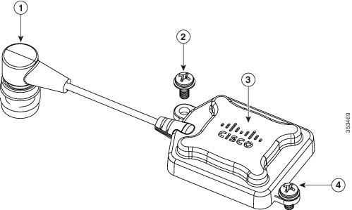
Installing the GPS Antenna
All models of the 1570 Series support location information when the optional GPS antenna (AIR-ANT-GPS-1) is installed and connected. The AP has two mounting positions for the GPS antenna, on the head of the AP and on the back of the AP, which need to be used depending on whether the AP is horizontally or vertically oriented when deployed (see Figure 4-19 and Figure 4-20).
Note![]() Ensure that the GPS antenna always has a clear unobstructed view of the sky, for proper functioning.
Ensure that the GPS antenna always has a clear unobstructed view of the sky, for proper functioning.
Step 1![]() Remove the protective cap covering the access point’s GPS antenna connector port.
Remove the protective cap covering the access point’s GPS antenna connector port.
Step 2![]() Screw down the GPS antenna connector onto the AP's GPS antenna connector port, just enough so that it doesn't fall off.
Screw down the GPS antenna connector onto the AP's GPS antenna connector port, just enough so that it doesn't fall off.
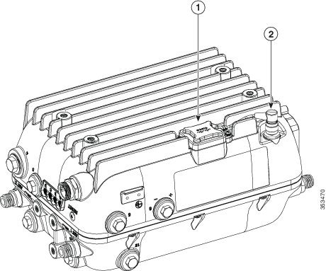
Step 3![]() If the AP is mounted horizontally, screw down the GPS antenna at the designated spot on the back of the AP (see Figure 4-19).
If the AP is mounted horizontally, screw down the GPS antenna at the designated spot on the back of the AP (see Figure 4-19).
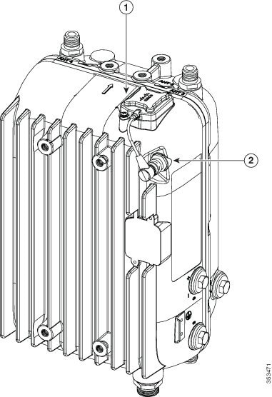
If the AP is mounted vertically, screw down the GPS antenna at the designated spot on the head of the AP (see Figure 4-20).
Step 4![]() The GPS antenna is fixed to the AP using two M3.5x0.6x8 mm Pan Head Phillips stainless steel screws.
The GPS antenna is fixed to the AP using two M3.5x0.6x8 mm Pan Head Phillips stainless steel screws.
Step 5![]() Fully tighten the GPS antenna connector onto the access point's GPS antenna connector port.
Fully tighten the GPS antenna connector onto the access point's GPS antenna connector port.
Figure 4-18 GPS Antenna and its connector
|
|
|
M3.5x0.6x8 mm Pan Head Phillips stainless steel screws, used to fasten the GPS antenna to the AP. |
|
|
|
|
Figure 4-19 GPS antenna installed on a horizontally oriented AP1572EC
|
|
|
GPS antenna connector plugged into AP’s antenna connector port |
Figure 4-20 GPS antenna installed on a vertically oriented AP1572EC
|
|
|
GPS antenna connector plugged into AP’s antenna connector port |
Installing Attenuators, Fuses, and Shunts
Installing an Attenuator Plug
You can install an attenuator plug on the RF splitter, in port 8 on the back of the access point (see Figure 1-4).
Plug-in attenuator pads produce flat (even) loss across the forward and reverse frequency spectrum. Pads are used during station balancing to adjust signal levels as needed. The loss (in dB) produced is equal to the pad value printed on the top of the pad.
Using a Signal Test Probe
You can use test probes (such as the Communication Associates CA008927) to measure the DS signal level directly from the attenuator plug-in interface in port 8 on the back of the access point (see Figure 1-4).
You need to remove any installed attenuator pads, which will disconnect the cable modem from the HFC network. You can then insert the test probe into the plug-in interface, providing an F-connector interface to directly measure downstream signal levels. Based on the measured signal level, you can decide on an attenuator value and then plug in the corresponding attenuator pad into the port.
Installing a Fuse or Shunt
You can install a power fuse or a power shunt in port 7 on the back of the access point (see Figure 1-4). Fuses with different fuse ratings are available from Cisco.
Note![]() By default a 20 A fuse is provided as shunt.
By default a 20 A fuse is provided as shunt.
Handling the AP when installing Attenuators, Fuses, and Shunts
To access port 7 or port 8 (see Figure 1-4):
- For strand mounted APs, you can access ports 7 and 8, without having to dislodge the AP from its mount.
- For pole and wall mounted APs, you can following one of the following procedures, depending on your mounting kit,
For pole mounted and wall mounted APs, mounted using PMK1 or PMK2, to access port 7 or port 8:
Step 1![]() Slide the AP up, off the wall mount bracket’s key hole slots.
Slide the AP up, off the wall mount bracket’s key hole slots.
Step 2![]() Remove the four M8 x 12mm hex head bolts from the back of the AP, and then fix them on the face of the AP in the screw holes intended for future external module support (see Face of the AP). Do not fully tighten the bolts.
Remove the four M8 x 12mm hex head bolts from the back of the AP, and then fix them on the face of the AP in the screw holes intended for future external module support (see Face of the AP). Do not fully tighten the bolts.
Step 3![]() With the face of the AP aligned to the wall mount bracket, slide bolts on the face of the AP, down into the key hole slots on the wall mount bracket.
With the face of the AP aligned to the wall mount bracket, slide bolts on the face of the AP, down into the key hole slots on the wall mount bracket.
Step 4![]() Unscrew the protector cap of the port and proceed with your task. When you are done with your task, retrace your steps to mount the AP back properly. See the following sections to ensure that you have properly mounted the AP.
Unscrew the protector cap of the port and proceed with your task. When you are done with your task, retrace your steps to mount the AP back properly. See the following sections to ensure that you have properly mounted the AP.
For pole mounted and wall mounted APs, mounted using PMK3, to access port 7 or port 8:
Step 1![]() Remove the three M8 x 12mm hex head bolts, used in the key hole type screw holes on the PMK3 wall mount bracket, as marked in Figure.
Remove the three M8 x 12mm hex head bolts, used in the key hole type screw holes on the PMK3 wall mount bracket, as marked in Figure.
Step 2![]() You can now rotate the AP outwards from the mount, using the remaining one bolt as the pivot. Rotate the AP out just enough access port 7 or 8.
You can now rotate the AP outwards from the mount, using the remaining one bolt as the pivot. Rotate the AP out just enough access port 7 or 8.
Note![]() You many need to loosen this bolt just enough to rotate the AP out.
You many need to loosen this bolt just enough to rotate the AP out.
Step 3![]() Unscrew the protector cap of the port and proceed with your task. When you are done with your task, retrace your steps to mount the AP back properly. See Pole Mount Kit 3 to ensure that you have properly mounted the AP.
Unscrew the protector cap of the port and proceed with your task. When you are done with your task, retrace your steps to mount the AP back properly. See Pole Mount Kit 3 to ensure that you have properly mounted the AP.
What to do after hardware installation
Once your AP and its accessories are installed, power up the AP. The following operating modes are supported by the 1570 series access points:
–![]() Flexconnect with Bridge Mode
Flexconnect with Bridge Mode
After the AP is powered up you can proceed with configuring the access point. For more information, see the following documents:
- For information on configuring a Lightweight Access Points and Mesh Access Points, see the Cisco Wireless LAN Controller Configuration Guide, release 8.0 or newer. The release 8.0 guide is available at:
http://www.cisco.com/c/en/us/td/docs/wireless/controller/8-0/configuration-guide/b_cg80.html
- For Access Points in autonomous mode, see the Cisco IOS Configuration Guide for Autonomous Aironet Access Points Cisco IOS Release 15.3(3)JAB, or newer. The 15.3(3)JAB guide is available at:
http://www.cisco.com/c/en/us/td/docs/wireless/access_point/15-3-3/configuration/guide/cg15-3-3.html
 Feedback