Q Signaling Configuration
Available Languages
Table Of Contents
Data Required to Provision QSIG PBXs
Call Routing in a QSIG Environment
Call from PBX 1 to Cisco Unified CallManager Cluster 1
Configuring QSIG Links and QSIG Intercluster Trunks
Cisco Unified CallManager Configuration for QSIG-Related Service Parameters
Cisco Catalyst 6500 Switch Configuration for QSIG Links
Cisco Unified CallManager Configuration for QSIG Links
Cisco Unified CallManager Configuration for QSIG Intercluster Trunks
Q Signaling Configuration
The Q Signaling (QSIG) protocol is a series of international standards that define services and signaling protocols for Private Integrated Services Networks (PISNs). In Cisco IP Communications Release 5.0(2) testing, a Cisco Unified CallManager cluster was connected through the QSIG to third-party PBXs and to another CallManager cluster.
This chapter provides an overview of the provisioning and configuration required for these connections. It also describes how calls are routed in a QSIG environment.
This chapter does not describe how QSIG features such as Call Back or Path Replacement work, nor does it explain why particular configuration values were used. It also does not provide detailed configuration instructions for third-party PBXs.
For additional information about QSIG, refer to the "Understanding IP Telephony Protocols" chapter in Cisco Unified CallManager System Guide, which is available at this URL:
http://www.cisco.com/univercd/cc/td/doc/product/voice/c_callmg/5_0/sys_ad/5_0_2/ccmsys/index.htm
This chapter includes the following topics:
•
Data Required to Provision QSIG PBXs
•
•
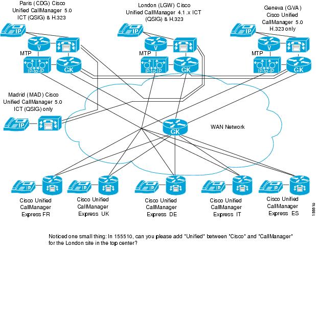
Overview
A Cisco Unified CallManager cluster was connected through QSIG to the following components:
•
•
Figure 13-1 illustrates these connections.
Figure 13-1 QSIG Connections to a Cisco Unified CallManager Clusters
Data Required to Provision QSIG PBXs
Table 13-1 describes the information that was used to provision third-party QSIG PBXs.
The PBX 1 and PBX 2 columns in this table show information for two sample QSIG PBXs. This information demonstrates the routing features that are available in a QSIG environment. The Cisco Unified CallManager column shows corresponding information that applies to the Cisco Unified CallManager in the Large Multi-Site Centralized with SRST site model (CDG).

Note
The "Call Routing in a QSIG Environment" section explains how calls are routed based on this information.
Call Routing in a QSIG Environment
The following sections describe how various calls are routed in a QSIG environment:
•
Call from PBX 1 to PSTN
A user in the PBX 1 domain can call the PSTN by dialing 9 and then the PSTN number
If the local PSTN connection is down or congested, or if the PBX does not have local PSTN access, the PSTN call can be routed via a designated alternate node through the QSIG trunk. In this case, only the PSTN number with the "9" prefix is sent across the QSIG trunk. Node numbers are not sent to route the call.
Call from PBX 1 to Cisco Unified CallManager Cluster 1
A user in the PBX 1 can call a user in the Cisco Unified CallManager Cluster 1 domain by dialing the node number followed by the extension. The call is routed directly to Cisco Unified CallManager Cluster 1 via the QSIG link 1.
If the direct QSIG link is down or congested, calls can be routed via a designated alternate node through the QSIG trunk. Node numbers are not sent to route the call.
Call from PBX 1 to PBX 2
A user in the PBX 1 domain can call a user in the PBX 2 domain by dialing the node number and extension in the PBX2 domain. The call is routed directly to PBX 2.
If the direct QSIG link is down or congested, calls can be routed via a designated alternate node through Cisco Unified CallManager. Node numbers are not sent to route the call.
Configuring QSIG Links and QSIG Intercluster Trunks
A Cisco Unified CallManager cluster in a QSIG environment is connected to other components in the following ways:
•
•
Table 13-2 lists the general procedures and references for configuring QSIG links.
Table 13-3 lists the general procedures and references configuring QSIG intercluster trunks.
Table 13-2 Steps and References for Configuring QSIG Links
Step 1
Configure service parameters in Cisco Unified CallManager Administration
See the "Cisco Unified CallManager Configuration for QSIG-Related Service Parameters" section
Step 2
Configure the Cisco Catalyst 6500 switch
See the "Cisco Catalyst 6500 Switch Configuration for QSIG Links" section
Step 3
Configure these items in Cisco Unified CallManager Administration, in this order:
•
•
•
•
See the "Cisco Unified CallManager Configuration for QSIG Links" section
Table 13-3 Steps and References for Configuring Intercluster Trunks
Step 1
Configure service parameters in Cisco Unified CallManager Administration
See the "Cisco Unified CallManager Configuration for QSIG-Related Service Parameters" section
Step 2
Configure QSIQ intercluster trunks in Cisco Unified CallManager Administration
See the "Cisco Unified CallManager Configuration for QSIG Intercluster Trunks" section
Cisco Unified CallManager Configuration for QSIG-Related Service Parameters
You must configure QSIG-related service parameters whether you use QSIG link or QSIG intercluster trunk connections.
To access the Cisco Unified CallManager Administration web pages for configuring service parameters, choose Service > Service Parameters from the Cisco Unified CallManager Administration application. Then select the appropriate server and select Cisco CallManager as the service.
Table 13-4 describes the configuration settings in the Service Parameters Configuration page. Fields not shown in this table were set to the suggested values that are shown in the Service Parameters Configuration page.
Note
Cisco Catalyst 6500 Switch Configuration for QSIG Links
The Cisco Unified CallManager cluster is configured to connect to a QSIG PBX via a QSIG link. The connection to the QSIG PBX was made via a Cisco Communication Media Module (CMM) card located in a Cisco Catalyst 6500 switch. QSIG links from the QSIG PBX were connected to the CMM card.
This section shows a configuration file for the Cisco Catalyst 6500 switch that was used for the QSIG inks.
version 12.4no parser cacheservice nagleno service padservice timestamps debug datetime msec localtime show-timezoneservice timestamps log datetime msec localtime show-timezoneno service password-encryption!hostname CDG_CMM-GW_1!boot-start-markerboot-end-marker!logging buffered 1000000 debuggingno logging rate-limitenable secret 5 $1$xxFL$03dDDqLocS9Nhhchg1yRZ0!no aaa new-model!resource policy!clock timezone GMT 0clock summer-time BST recurringmmi polling-interval 60no mmi auto-configureno mmi pvcmmi snmp-timeout 180ip subnet-zerono ip source-routeip tcp synwait-time 5!ip ftp username Administratorip ftp password ciscono ip domain lookupip host cdg-sub7 10.10.110.73ip host cdg-sub8 10.10.110.11ip host cdg-pub 10.10.110.5ip host cdg-moh 10.10.110.6ip host cdg-tftp 10.10.110.69ip host cdg-sub1 10.10.110.70ip host cdg-sub2 10.10.110.7ip host cdg-sub3 10.10.110.71ip host cdg-sub4 10.10.110.8ip host cdg-sub5 10.10.110.72ip host cdg-sub6 10.10.110.9ip rcmd rcp-enableip rcmd rsh-enable!isdn switch-type primary-net5!controller E1 1/0framing NO-CRC4clock source line primarypri-group timeslots 1-31 service mgcp!controller E1 1/1framing NO-CRC4clock source line secondary 1pri-group timeslots 1-31 service mgcp!controller E1 1/2framing NO-CRC4clock source line secondary 2pri-group timeslots 1-31 service mgcp!controller E1 1/3pri-group timeslots 1-31 service mgcp!controller E1 1/4pri-group timeslots 1-31 service mgcp!controller E1 1/5!interface GigabitEthernet1/0ip address 10.10.110.4 255.255.255.192no ip proxy-arpno negotiation autono keepalive!interface Serial1/0:15no ip addressencapsulation hdlcno logging event link-statusisdn switch-type primary-net5isdn incoming-voice voiceisdn bind-l3 ccm-managerno cdp enable!interface Serial1/1:15no ip addressencapsulation hdlcno logging event link-statusisdn switch-type primary-net5isdn incoming-voice voiceisdn bind-l3 ccm-managerno cdp enable!interface Serial1/2:15no ip addressencapsulation hdlcno logging event link-statusisdn switch-type primary-net5isdn incoming-voice voiceisdn bind-l3 ccm-managerno cdp enable!interface Serial1/3:15no ip addressencapsulation hdlcno logging event link-statusisdn switch-type primary-qsigisdn protocol-emulate networkisdn incoming-voice voiceisdn T310 120000isdn bind-l3 ccm-managerno cdp enable!interface Serial1/4:15no ip addressencapsulation hdlcno logging event link-statusisdn switch-type primary-qsigisdn protocol-emulate networkisdn incoming-voice voiceisdn T310 120000isdn bind-l3 ccm-managerno cdp enable!interface FastEthernet3/0description Conference Bridge addressip address 10.10.110.30 255.255.255.255no ip proxy-arpfull-duplex!ip classlessip route 0.0.0.0 0.0.0.0 10.10.110.1!no ip http serverno ip http secure-server!logging facility local6logging 10.10.15.20snmp-server community private ROsnmp-server community public RWsnmp-server chassis-id CDG_CMM-GW_1snmp-server enable traps snmp authentication linkdown linkup coldstart warmstartsnmp-server host 10.10.15.20 public!control-plane!voice-port 1/0:15echo-cancel coverage 128cptone FR!voice-port 1/1:15echo-cancel coverage 128cptone FR!voice-port 1/2:15echo-cancel coverage 128cptone FR!voice-port 1/3:15echo-cancel coverage 128cptone GB!voice-port 1/4:15echo-cancel coverage 128cptone GB!ccm-manager redundant-host cdg-sub2ccm-manager mgcpccm-manager music-on-holdccm-manager config server 10.10.110.69ccm-manager config!mgcpmgcp call-agent cdg-sub1 2427 service-type mgcp version 0.1mgcp dtmf-relay voip codec all mode out-of-bandmgcp rtp unreachable timeout 1000 action notifymgcp modem passthrough voip mode nsemgcp package-capability rtp-packageno mgcp package-capability res-packagemgcp package-capability sst-packagemgcp package-capability pre-packageno mgcp timer receive-rtcpmgcp sdp simplemgcp fax rate 14400mgcp fax t38 inhibitmgcp rtp payload-type g726r16 static!mgcp profile default!mediacard 4resource-pool trans dsps 2resource-pool conf dsps 2!sccp local GigabitEthernet1/0sccp ccm 10.10.110.72 identifier 2 version 5.0.1sccp ccm 10.10.110.9 identifier 1 version 5.0.1sccp!sccp ccm group 1associate ccm 1 priority 1associate ccm 2 priority 2associate profile 2 register M120003E4729A00associate profile 1 register C100003E4729A00!dspfarm!dspfarm profile 1 conference adhoccodec g711ulaw packetization-period 20codec g711alaw packetization-period 20codec g729r8 packetization-period 30codec g729ar8 packetization-period 30codec g723r63 packetization-period 30codec g723r53 packetization-period 30associate resource-pool conf!dspfarm profile 2 transcodecodec g711ulaw packetization-period 20codec g711alaw packetization-period 20codec g729r8 packetization-period 30codec g729ar8 packetization-period 30codec g723r63 packetization-period 30codec g723r53 packetization-period 30associate resource-pool trans!line con 0exec-timeout 60 0privilege level 15logging synchronousline vty 0 4exec-timeout 60 0privilege level 15password ciscologging synchronouslogin!ntp clock-period 17180040ntp server 192.168.253.5ntp server 192.168.253.1!endCisco Unified CallManager Configuration for QSIG Links
The following sections describe the configurations that were made in Cisco Unified CallManager Administration for QSIG link connections:
Note
Gateway Configuration
The CMM card installed in the Cisco Catalyst 6500 Switch serves as the gateway through which the QSIG link to the QSIG PBX is connected. This section shows how the CallManager cluster was configured to control the CCM card.
To access the Cisco Unified CallManager Administration web pages for adding and configuring gateways, choose Device > Gateway from the Cisco Unified CallManager Administration application.
Table 13-5 describes how a the CMM card was configured in the Gateway Configuration page.
After the gateway is configured, configure the interfaces where the QSIG links to the PBX are connected on the gateway. Three such interfaces were configured: S1/DS1-3, S1/DS1-4, and S1/DS1-5. Table 13-6 describes how the S1/DS1-3 interface was configured. The other interfaces were configured similarly.
Route Group Configuration
To access the Cisco Unified CallManager Administration web pages for adding and configuring route groups, choose Route Plan > Route/Hunt > Route Group from the Cisco Unified CallManager Administration application.
The following route group members were configured for the QSIG-702-GRP route group:
•
•
•
Route List Configuration
To access the Cisco Unified CallManager Administration web pages for adding and configuring route lists, choose Route Plan > Route/Hunt > Route List from the Cisco Unified CallManager Administration application.
Table 13-7 describes how the route list was configured in the Route List Configuration page.
Route Pattern Configuration
To access the Cisco Unified CallManager Administration web pages for adding and configuring route patterns, choose Route Plan > Route/Hunt > Route Pattern from the Cisco Unified CallManager Administration application.
Table 13-8 describes how the route pattern for the QSIG PBX was configured in the Route Pattern Configuration page.
Cisco Unified CallManager Configuration for QSIG Intercluster Trunks
This sections describes the configurations that were made in Cisco Unified CallManager Administration for QSIG intercluster trunk connections.
To access the Cisco Unified CallManager Administration web pages for configuring trunks, choose Device > Trunk from the Cisco Unified CallManager Administration application.
Table 13-9 describes how the intercluster trunk was configured in the Trunk Configuration page.
A similar intercluster was configured in Cisco Unified CallManager Cluster 2. This configuration includes the IP addresses of the Cisco Unified CallManager Cluster 1 servers in the Remote Cisco Unified CallManager Information fields.
 Feedback
Contact Cisco
- Open a Support Case

- (Requires a Cisco Service Contract)
This Document Applies to These Products
- Collaboration Endpoints - Retired Products
- Conferencing - Retired Products
- Contact Center - Retired Products
- Optical Networking - Retired Products
- Routers - Retired Products
- Security - Retired Products
- Servers - Unified Computing (UCS) Retired Products
- Storage Networking Retired Products
- Switches - Retired Products
- Video - Retired Products
- Wireless - Retired Products