Chapter 6: Cisco Signaling Link Terminal Maintenance
Available Languages
Table Of Contents
Maintaining the Cisco Signaling Link Terminal
Using the Cisco SLT Operating System to Check Status
Mounting the Chassis in a Rack
Installing the Cisco SLT in a Rack
Connecting the DC Power Supply
Connecting the Console Terminal and Modem
Connecting to the Console Port
Installing a WAN Interface Card
Replacing the System-Code SIMM
Preparing to Install the System-Code SIMM
Procedures for Recovering Boot and System Images
Maintaining the Cisco Signaling Link Terminal
This chapter contains the recommended hardware maintenance procedures for the Cisco Signaling Link Terminal (SLT), which is designed to perform SS7 signal pre-processing for a Cisco Media Gateway Controller. The Cisco SLT consists of a custom Cisco IOS image running on a Cisco 2611 router. For information on upgrading and maintaining Cisco SLT software, refer to the Cisco Signaling Link Terminal documentation.
As part of an end-to-end telephony solution, the Cisco SLT provides reliable transport of Signaling System 7 (SS7) protocols across an IP network. The Cisco SLT uses the Cisco IOS SS7 Cisco SLT feature set, providing reliable interoperability with the Cisco Media Gateway Controller (MGC). The Cisco SLT uses Cisco's Reliable User Datagram Protocol (RUDP) to backhaul upper-layer SS7 protocols across an IP network.
When used for Signal Link Terminal applications, the modular Cisco 2611 dual Ethernet port router can be configured with dual serial as well as Multiflex WAN interface cards with integrated E1 data service units (DSUs) or T1 channel service units (CSUs)/DSUs. For additional flexibility, the Multiflex WAN interface cards can also be ordered with a dual-port Drop and Insert capability.
The following interface cards are supported:
•
1-port high-speed serial interface (WIC-1T)
•
•
•
•
•
•
•
Only SS7 serial interfaces and protocols are supported. There is no support for non-SS7 serial WAN protocols. Only two SS7 signaling links are supported per Cisco SLT, and only one SS7 signaling link is supported per T1 or E1 port.

Note
This chapter describes Cisco SLT hardware maintenance and includes the following sections:
•
Checking Equipment Status
You can check the status of the Cisco SLT devices using the following methods:
•
•
•
Cisco SLT LEDs
LEDs indicate the current operating condition of the Cisco SLT.
Front-Panel LEDs
Figure 6-1 shows the location of the LEDs on the Cisco SLT. Table 6-1 describes these LEDs.
Figure 6-1 Cisco SLT Front-Panel LEDs

Table 6-1 Cisco SLT Front-Panel LEDs
Power
Indicates the Cisco SLT operating status. Goes on when power is supplied to the Cisco SLT and the Cisco SLT is operational.
RPS
OFF—No RPS1 is attached.
ON—RPS is attached and operational.
Blink—RPS is attached, but has a failure.Activity
OFF—In the Cisco IOS software, but no network activity.
Blink (500 ms ON, 500 ms OFF)—In Remote Monitor (ROMMON), no errors.
Blink (500 ms ON, 500 ms OFF, 2 sec. between codes)—In ROMMON, error detected.
Blink (less than 500 ms)—In the Cisco IOS software, the blink rate reflects the level of activity.
1 RPS = Redundant Power System.
Rear-Panel LEDs
Figure 6-2 shows the location of the Cisco SLT rear-panel LEDs. Table 6-2 describes these LEDs.
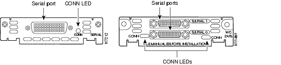
Figure 6-2 Cisco SLT Rear-Panel LEDs

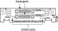
WIC LEDs
Each serial card has one LED, labeled CONN for each port, which lights when the serial port is connected. When the port is in DTE mode, the CONN LED indicates that Data Set Ready (DSR), Data Carrier Detect (DCD), and Clear To Send (CTS) have been detected. When the port is in DCE mode, it indicates that Data Terminal Ready (DTR) and Request To Send (RTS) have been detected.
Figure 6-3 1- and 2-Port Serial WAN Interface Card LEDs
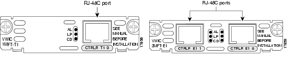
VWIC LEDs
You can distinguish between T1 and E1 interface cards by the labeling on the faceplate, as shown in Figure 6-4. Each multiflex trunk interface card has three LEDs, which are shown in Figure 6-4 and described in Table 6-3.
Figure 6-4 1- and 2-Port T1 and E1 Multiflex Trunk Interface Card LEDs
Using the Cisco SLT Operating System to Check Status
The Cisco SLT operating system includes a series of commands that enable you to determine if the unit is functioning correctly or where problems have occurred. A few of the relevant commands for checking status are listed here. To learn how to find more information concerning these and other IOS commands, refer to the Cisco IOS Software Documentation Organization.
Status commands that may help to monitor the health and state of your Cisco SLT at any given time include the following:
•
•
•
•
•
•
•
•
•
•
•
•
•
•
•
Note
Removing a Cisco SLT
This section describes how to shut down a Cisco SLT and remove it. The assumption is that the system has been properly installed according to procedures described in the Cisco Media Gateway Controller Hardware Installation Guide, most notably the following procedures:
•
•
•
Required Tools and Equipment
Following are the tools and parts that might be required for removing a Cisco SLT:
•
•
•
It is also assumed that the cables and console terminal were installed during the original system installation.
Procedure
To remove the Cisco SLT, complete the following steps:
Step 1
Step 2
Step 3
Step 4
Replacing a Cisco SLT
This section describes how to install a new Cisco SLT or reinstall a repaired Cisco SLT.
Required Tools and Equipment
Following are the tools and parts that might be required for replacing a Cisco SLT:
•
•
•
•
It is assumed that cables, Ethernet hub, and the console terminal remain from the original installation.
Mounting the Chassis in a Rack
This section describes the procedures for rack-mounting the chassis. A new chassis comes with brackets for use with a 19-inch rack or, if specified in your order, optional larger brackets for use with a 24-inch rack. The brackets are shown in Figure 6-5.

Warning
•
•
•
Figure 6-5 Identifying the Brackets

Attaching the Brackets
To install the chassis in a rack, attach the brackets in one of the following ways:
•
•
•
Note
Note
If you are installing a Cisco SLT in a 19-inch EIA-standard rack with a 17.75-inch opening or a 23- or 24-inch rack, orient the rack-mount brackets so that, when installed, they increase the width of the chassis. (See Figure 6-7.)
Note
Figure 6-6 Bracket Installation—Front Panel Forward (19-Inch Rack with a 17.5-Inch Opening)
Note
Figure 6-7 Bracket Installation—Front Panel Forward (19-Inch Rack with a 17.75-Inch Opening or a 23-inch or 24-Inch Rack)
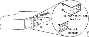
Figure 6-8 Bracket Installation—Rear Panel Forward (19-Inch Rack with a 17.5-Inch Opening)
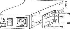
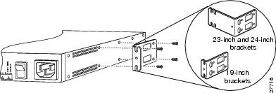
Figure 6-9 Bracket Installation—Rear Panel Forward (19-Inch Rack with a 17.75-Inch Opening or a 23-inch or 24-Inch Rack)
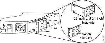
Figure 6-10 Center-Mount Bracket Installation—Rear Panel Forward
Installing the Cisco SLT in a Rack
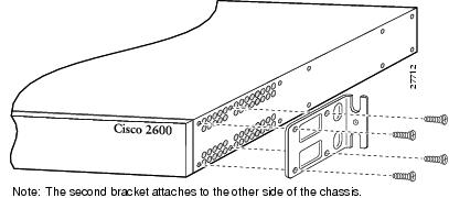
After the brackets are secured to the chassis, you can rack-mount the Cisco SLT. Using the screws you provide, attach the chassis to the rack as shown in Figure 6-11.
Figure 6-11 Attaching the Chassis to a Rack—Rear Panel Forward

Connecting the DC Power Supply
This section describes the DC power supply specifications and wiring.
Warning
DC Power Specifications
The DC power supply is intended for use in DC-operating environments. Table 6-4 lists the power supply specifications.
Table 6-4 Power Supply Specifications
Power (input)
40W, -38 to -75 VDC
Wire gauge for power connections
14 AWG1
1 AWG = American Wire Gauge.
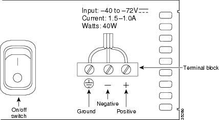
Wiring the DC Power Supply
If you ordered a Cisco SLT with a DC power supply, follow the directions in this section to wire the terminal block.
Warning
Warning

Caution
Warning
Warning
Note
To wire the terminal block, complete the following steps:
Step 1
Step 2
Figure 6-12 DC Power Supply Connections
Connecting to a Network
This section explains how to connect the Cisco SLT to the control signaling LAN. It is assumed that the cables required to connect the Cisco SLT to the LAN are available from the Cisco SLT being replaced.
Warning
Connect the Ethernet 10BaseT port to an Ethernet 10BaseT port on the LAN switch.
Connecting the Console Terminal and Modem
Cisco SLTs include asynchronous serial console and auxiliary ports. These ports provide local administrative access to your Cisco SLT (with a console terminal) or remote access (with a modem).
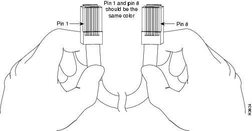
Identifying a Rollover Cable
Use a rollover cable to connect to the asynchronous serial console and auxiliary ports. You can identify a rollover cable by comparing the two modular ends of the cable. When you hold the two cable ends side-by-side with the tab at the back, as shown in Figure 6-13, the wire connected to the pin on the outside of the left plug should be the same color as the wire connected to the pin on the outside of the right plug. If your cable came from Cisco Systems, pin 1 is white on one connector, and pin 8 is white on the other (a rollover cable reverses pins 1 and 8, 2 and 7, 3 and 6, and 4 and 5).
Figure 6-13 Identifying a Rollover Cable
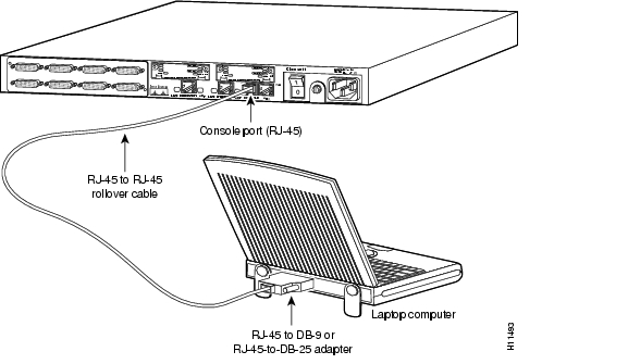
Connecting to the Console Port
Take the following steps to connect a terminal (an ASCII terminal or a PC running terminal emulation software) to the console port on the Cisco SLT:
Step 1
Step 2
For information on console port pinouts, see the online document Cisco Modular Access Router Cabling Specifications on the Documentation CD-ROM that accompanied your Cisco SLT package.
Figure 6-14 Connecting a Console Terminal
Cisco SLT Interface Numbering
Each individual network interface on a Cisco SLT is identified by a slot number and a unit number. The Cisco SLT chassis contains one slot in which you can install a network module. Figure 6-15 shows the slot location in the Cisco SLT chassis.
Figure 6-15 Cisco SLT WAN Interface Card Chassis Slot Locations
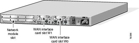
Unit numbers identify the interfaces on the modules installed in the unit. Unit numbers begin at 0 for each interface type, and continue from right to left and from bottom to top. Modules are identified by interface type, slot number (always 0), a forward slash (/), then the unit number. For example:
•
•
•
Note
Install the New Software
After you have installed the Cisco SLT, power it on. (If the Cisco SLT does not power on, proceed to "Troubleshooting Cisco SLT Signaling.")
After the hardware has been installed and powered on, you must configure the Cisco SLT. Refer to the Cisco Media Gateway Controller Software Release 7 Installation and Configuration Guide.
After the Cisco SLT has been configured, you must install a special release of the Cisco IOS software on the Cisco SLT. The filename of the current Cisco SLT image is c2600-ipss7-mz.121-1.T.bin.
To copy a system image from a Trivial File Transfer Protocol (TFTP) server to a Flash memory file system, use the following command in EXEC mode:
copy tftp:[[[//location]/directory]/filename] flash-filesystem:[filename]Replacing Hardware Components
Each Cisco SLT is equipped with at least one WAN interface card. This section describes how to replace the WAN interface cards in the Cisco SLTs, and contains the following subsections:
•
Figure 6-16 shows the WIC-2T WAN interface card.
Figure 6-16 WIC-2T Dual Port Serial WAN Interface Card
Required Tools and Equipment
In addition to the WIC and the Cisco SLT, you will need these items to install and connect your card:
•
•
•
Installing a WAN Interface Card
This section describes the procedure for installing a WIC-2T WAN interface card in a Cisco SLT slot.
You can install the WIC-2T either before or after mounting the Cisco SLT, whichever is more convenient. Similarly, you can install the WIC-2T in the network module either before or after installing the network module in the Cisco SLT chassis.
Caution
Warning
To install WAN interface cards in a Cisco SLT WIC chassis slot, complete the following procedure:
Step 1
Note
Step 2
a.
b.
c.
d.
The following warning applies only to Cisco SLTs that use a DC power supply:
Warning
WIC Filler Panels
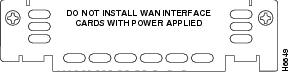
If any interface card slot (on the network module or chassis) is unoccupied, install a filler panel to enable proper airflow. (See Figure 6-17.)
Figure 6-17 WIC Slot Filler Panel
Additional Maintenance Tasks
This section contains selected maintenance procedures you might need to perform on a Cisco SLT as your internetworking needs change, including the following:
•
•
Additional maintenance procedures are available on the Documentation CD-ROM that shipped with the Cisco SLT.
To see translated versions of warnings in this section, see the Regulatory Compliance and Safety Information document that accompanied your Cisco SLT.
Caution
Warning
Upgrading DRAM
This section describes how to upgrade dynamic random-access memory (DRAM) on the system card. You might need to upgrade DRAM if you have loaded a new Cisco IOS software feature set or release.
To see how much memory is currently installed in the Cisco SLT, enter the show version command. Near the middle of the resulting output, a message similar to the following appears:
Cisco 2611(MPC860) processor (revision 0x200) with 28672K/4096K bytes of memory.This line shows how much memory is installed (in this example, 28672 K/4096 K). The first number represents primary memory, and the second number represents shared memory.
For information about recommended DRAM part numbers for your Cisco SLT, refer to the Cisco 2600 Series Hardware Installation Guide.
Cisco SLT DRAM
Cisco SLTs contain two 100-pin dual in-line memory module (DIMM) sockets (or banks) for DRAM, numbered 0 and 1. (See Figure 6-20.) Each socket can be filled with a 100-pin DRAM DIMM. You can use the memory-size iomem software command to configure DRAM as a mixture of shared memory, which is used for data transmitted or received by network modules and WAN interface cards, and primary or main memory, which is reserved for the CPU. For further information about this command, see the Cisco IOS configuration guides and command references.
Opening the Chassis
This section describes the procedure for opening the chassis by removing the chassis cover.
Warning
Tools Required
You will need the following tools to remove and replace the DRAM DIMMs on the Cisco SLT:
•
•
•
Removing the Chassis Cover
You must open the chassis to access the internal components.
Warning
To remove the chassis cover, complete the following steps:
Step 1
Step 2
Step 3
Step 4
Step 5
Figure 6-18 Holding Chassis for Cover Removal
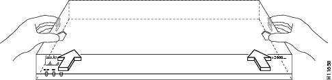
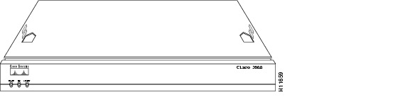
Figure 6-19 Removing Chassis Cover
Step 6
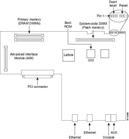
system cards.
Figure 6-20 System Card Layout
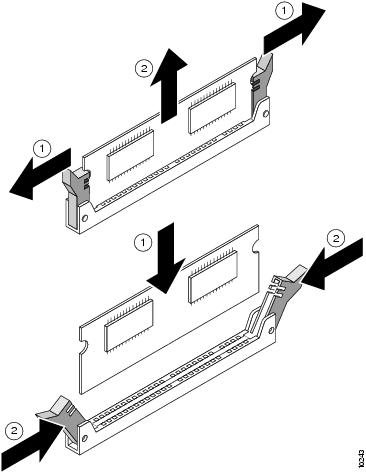
DRAM DIMM Installation
Take the following steps to install the DRAM DIMMs:
Step 1
Step 2
Step 3
Step 4
Caution
Step 5
Figure 6-21 Removing and Replacing the DRAM DIMM
Step 6
Step 7
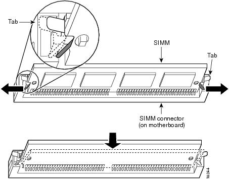
Replacing the System-Code SIMM
The system code (Cisco SLT operating system software) is stored in a Flash memory 80-pin single in-line memory module (SIMM).
For information about recommended SIMM part numbers for your Cisco SLT, refer to the Cisco 2600 Series Hardware Installation Guide.
Tools Required
You will need the following tools to remove and replace the system-code SIMM on the Cisco SLT:
•
•
•
Preparing to Install the System-Code SIMM
There is one system-code (Flash memory) SIMM socket on the system board. You can verify how much Flash memory is already installed in your Cisco SLT by entering the show flash EXEC command.
Caution
Note
System-Code SIMM Replacement
Take the following steps to upgrade the system-code Flash memory SIMM:
Step 1
Step 2
Step 3
Step 4
Step 5
Step 6
Step 7
Step 8
Caution
Step 9
Step 10
Refer to the "Procedures for Recovering Boot and System Images" section for instructions on how to place the Cisco IOS image on the new SIMM.
Figure 6-22 Removing and Replacing the System-Code SIMM
Closing the Chassis
This section describes the procedure for closing the chassis by replacing the chassis cover.
Replacing the Cover
To replace the cover, complete the following steps:
Step 1
Step 2
Caution
Step 3
Step 4
Step 5
Step 6
Procedures for Recovering Boot and System Images
If your Cisco SLT experiences difficulties and no longer contains a valid Cisco IOS software image in Flash memory, you can recover the Cisco IOS image using the procedures described in the Cisco Signaling Link Controller documentation.
 Feedback