Appendix B: Troubleshooting Cisco SLT Signaling
Available Languages
Table Of Contents
Troubleshooting Cisco SLT Signaling
Troubleshooting SS7 Link Problems
Checking Link Configuration Files
Checking Connection between Cisco MGC and Cisco SLT
Verifying the Link Alignment Status
Verifying Exchanged Point Codes
Cross-Checking Configuration Files
Troubleshooting Cisco SLT-to-STP Signaling Links
Identifying MTP1 Communication Problems
Resolving MTP1 Communication Problems
Identifying MTP2 Communication Problems
Resolving MTP2 Communication Problems
Troubleshooting Cisco SLT to Cisco MGC Communications
Identifying MTP3 and Higher Layer Problems
Resolving MTP3 and Higher Layer SS7 Communication Problems
Identifying Ethernet Connectivity Problems
Identifying IP Communication Problems
Troubleshooting Cisco SLT Signaling
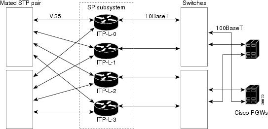
Several Cisco 2600 series modular access routers can be utilized as hardware components called Cisco Signaling Link Terminals (SLTs). Cisco SLTs function as signaling link interfaces to SS7 Signal Transfer Point (STP) mated pairs on the SS7 network side. On the LAN side, Cisco SLTs function as IP interfaces to the Cisco Media Gateway Controllers (MGCs). A number of different SS7 messages pass between the Cisco SLTs and STPs and between the Cisco SLTs and Cisco MGCs through Cisco Catalyst Multiswitch Routers (MSRs), which are used as LAN switches.
Each STP in a mated pair is constantly active under normal operating conditions. SS7 message traffic normally flows between both STPs of the mated pair and the Cisco SLTs, as shown in Figure B-1.
Figure B-1 Cisco SLT Hardware and I/O Signaling
This chapter includes the following sections:
•
Troubleshooting SS7 Link Problems
•
•
Cisco SLT Signaling Overview
This section contains the following subsections:
IP Signaling Backhaul
IP signaling backhaul is accomplished by means of the Cisco-proprietary Reliable User Datagram Protocol (RUDP) for communication between the Cisco SLT and the Cisco MGC.
Backhaul messages can be traced from the Cisco SLT command line interface (CLI) by means of the command
debug ss7 mtp2 backhaul channelIP signaling backhaul is described in the following sections:
Types of Encapsulation
There are two different types of data encapsulation associated with IP signaling backhaul messages:
•
•
PDU Verb Types
There are three different PDU verb types associated with IP signaling backhaul commands and messages:
•
•
•
Backhaul Message IDs
There are five types of IP signaling backhaul message IDs:
•
•
•
•
•
Backhaul Reset
There are two types of IP signaling backhaul reset commands:
•
Sample message trace:
00:10:18: SoftResetRequest•
Sample message trace:
00:10:18: HardResetRequestConnection Management
There are two IP signaling backhaul connection commands; a connection request and a disconnect request. Each command has a corresponding confirmation message.
•
•
Sample message trace: 4d10h: MTP2: rcvd Conn Req - Emergency ch=0 Statistics—
•
The Cisco SLT transmits a status indicator, an Out-of-Service (SIOS) message on the SS7 link.
•
•
Sample message trace: 4d10h: MTP2: send Disc Ind ch=0 reason=0x7-LSSU condition
The following sections describe connections management:
Backhaul Statistics
There are two IP signaling backhaul statistics messages:
•
An action value is provided to accomplish one of three options: (1) return the statistics and reset the statistics collection, (2) just return the statistics, or (3) just reset the statistics collection.
•
Sample message trace: 4d10h: MTP2: rcvd Statistics Req-Send&Reset ch=0Backhaul Congestion
The Cisco SLT uses the congestion indication, an asynchronous message sent from the Cisco SLT to the Cisco MGC to indicate that its backhaul signaling link is entering (Onset) or exiting (Abate) congestion.
Sample message trace:
Mar 1 005616.707 MTP2 send Flow Ind ch=0 status=0x0 start congestionThe Cisco SLT has two types of possible congestion. Both are determined in the same manner, but control flow in different directions.
•
•
Congestion onset and abatement are determined by the percentage of free receive buffers.
•
When the number of free receive buffers drops below 20 percent, a backhaul congestion onset message is sent from the Cisco SLT to the Cisco MGC. At this point, the Cisco MGC holds all backhaul traffic destined for the Cisco SLT.
•
When the number of free receive buffers rises above 40 percent, a backhaul congestion abate message is sent from the Cisco SLT to the Cisco MGC. At this point, the Cisco MGC resumes sending backhaul traffic destined for the Cisco SLT.
Link Status
Congestion status is maintained for backhaul.
Example of a congestion status message:
Nomad-C#sho ss7 mtp2 stateSS7 MTP2 states for channel 0Protocol version for channel 0 is Bellcore GR-246-Core Issue 2, Dec 1997MTP2LSC_INSERVICE MTP2IAC_IDLEMTP2TXC_INSERVICE MTP2RC_INSERVICEMTP2SUERM_MONITORING MTP2AERM_IDLEMTP2CONGESTION_IDLECongestion Backhaul = AbateRemote Processor Outage = FALSETroubleshooting SS7 Link Problems
The following sections describe methods of troubleshooting SS7 link problems:
•
•
•
•
•
•
Checking Link Configuration Files
Check the configuration files on the Cisco MGC and the Cisco SLT. The IP addresses and UPD ports must match.
•
–
–
•
–
–
–
Checking UDP Traffic Flows
Check UDP traffic flows between the Cisco MGC and the Cisco SLT by entering the following commands:
log on 2600, enable
debug ip udp
The response should look like the following, again depending on your configuration:
2600-1#deb ip udpUDP packet debugging is on2600-1#15:06:53: UDP: rcvd src=10.15.13.6(7000), dst=10.15.13.2(7000), length=3215:06:53: UDP: rcvd src=10.15.13.6(7000), dst=10.15.13.2(7000), length=3215:06:53: UDP: sent src=10.15.13.2(7000), dst=10.15.13.6(7000), length=16415:06:53: UDP: sent src=10.15.13.2(7000), dst=10.15.13.6(7000), length=16415:06:53: UDP: rcvd src=10.15.13.6(7000), dst=10.15.13.2(7000), length=1215:06:55: UDP: sent src=10.15.13.2(7000), dst=10.15.13.6(7000), length=3215:06:55: UDP: rcvd src=10.15.13.6(7000), dst=10.15.13.2(7000), length=12un allCheck for traffic in both directions. If there is traffic, go to the "Checking Connection between Cisco MGC and Cisco SLT" section.
Otherwise, verify IP addresses, try to ping in both directions, reload the Cisco SLT software, check subnets, and check the VLANs on the LAN switches.
Checking Connection between Cisco MGC and Cisco SLT
Check that the Cisco MGC connects to the Cisco SLT:
debug ss7 mtp2 backhaul ip upd NWhere N = 0, 1, 2, or 3, which identifies the specific MTP link.
The Cisco SLT will not attempt to align the link until it has received an MTP3 Connect Indication from the Cisco MGC. The MTP3 primitives between the Cisco SLT and the Cisco MGC can be seen with this debug command.
Checking the T1/E1 Link State
Check the T1 or E1 link state by observing the LEDs on the Cisco SLT. Make sure that the framing options match on both sides of the physical link.
Verifying the Link Alignment Status
Check alignment status of a link by entering the following debug command:
debug ss7 mtp2 iac NWhere N is a number (0, 1, 2, or 3) that identifies the specific MTP link.
Table B-1 describes various debug outputs from the previous command, the probable cause, and the recommended recovery. This traffic is exchanged only when the link is initially brought up. If the link is already In-Service, nothing is displayed.
Table B-1 Debug Outputs, Probable Causes, and Recovery Actions
No output.
Link is already aligned.
MTP2 is not started.
1. Check that term monitor is on.
2. Reload Cisco SLT.
3. Cross-check configuration files.
MTP2 does not flow across the link.
Check DS0 assignment (should use the same time slot on both sides of the physical link) and the DS0 speed (defaults to 56 kbps on T1 and 64 kbps on E1). The DS0 speed can be changed by
conf t
contr E1 0/0
channel-group 0
timeslot 1 speed 56The link is able to align, but fails in the PROVING sequence.
It is generally a mismatch in point codes.
Check the provisioning settings for the SLC, OPC, and DPC in the Cisco MGC, as described in the "Bouncing SS7 Links" section.
You can use an SS7 sniffer tool to look at the exchanged point codes. The procedure in "Verifying Exchanged Point Codes" section allows you to get them using Cisco SLT debug tools.
Verifying Exchanged Point Codes
Check exchanged point codes by entering the following command:
debug ss7 mtp2 pac NWhere: N = 0, 1, 2, or 3 identifies the MTP link
Table B-2 describes various debug outputs from this command, the probable cause, and the recommended recovery.
Cross-Checking Configuration Files
Cross-check the configuration files by entering the following command:
2600-1#deb ss7 mtp2 iac 0You should see a response similar to the following Cisco MGC sample configuration file:
File: XECfgParm.dat (extract)*.ipAddrLocalA = 10.15.13.6 # Should be same as *.IP_Addr1*.ipAddrLocalB = 10.15.13.22*.ipAddrPeerA = 0.0.0.0 # Failover peer's address*.ipAddrPeerB = 0.0.0.0*.IP_Addr1 = 10.15.13.6 # Address of interface on motherboard*.IP_Addr2 = 10.15.13.22*.IP_Addr3 = 0.0.0.0*.IP_Addr4 = 0.0.0.0*.stPort = 0This file defines the Cisco MGC IP addresses used to communicate with the Cisco SLT.
To check if they match with the Solaris configuration, you can use ifconfig -a Solaris command.
File: sigChanDev.dat001d0001 0 1 00080002 00030014 00060001 0001d0002 0 1 00080001 00030014 00060001 1001d0003 1 1 00080001 00030014 00060002 1001d0004 1 1 00080002 00030014 00060002 0001d0005 2 1 00080002 00030014 00060001 0001d0006 2 1 00080001 00030014 00060001 1001d0007 3 1 00080001 00030014 00060002 1001d0008 3 1 00080002 00030014 00060002 0
Note
File: sigChanDevIp.dat001d0001 IP_Addr1 7000 10.15.13.2 7000001d0002 IP_Addr1 7000 10.15.13.2 7000001d0003 IP_Addr2 7000 10.15.13.19 7000001d0004 IP_Addr2 7000 10.15.13.19 7000001d0005 IP_Addr1 7000 10.15.13.4 7000001d0006 IP_Addr1 7000 10.15.13.4 7000001d0007 IP_Addr2 7000 10.15.13.21 7000001d0008 IP_Addr2 7000 10.15.13.21 7000This file associates the Cisco MGC IP address/UDP port to the Cisco SLT IP address/UDP port. IP_Addr1 and IP_Addr2 are defined in XECfgParm.dat.
These files should not be edited using vi. Any change is lost when provisioning tools are used. The only exception is XECfgParm.dat (and changes can be lost anyway).
Cisco SLT sample configuration:
controller T1 0/0framing esflinecode b8zschannel-group 0 timeslots 1!controller T1 0/1framing esflinecode b8zschannel-group 0 timeslots 1!interface Ethernet0/0ip address 10.15.13.2 255.255.255.240no ip directed-broadcast!interface Serial0/0:0no ip addressno ip directed-broadcast!interface Ethernet0/1ip address 10.15.13.18 255.255.255.240no ip directed-broadcast!interface Serial0/1:0no ip addressno ip directed-broadcast!ip classlessip route 172.18.0.0 255.255.0.0 10.15.13.1no ip http server!ss7 set failover-timer 3ss7 session-0 address 10.15.13.6 7000 10.15.13.2 7000ss7 session-0 retrans_t 600ss7 session-0 cumack_t 300ss7 session-0 kp_t 2000ss7 session-0 m_retrans 2ss7 session-0 m_cumack 3ss7 session-0 m_outseq 3ss7 session-0 m_rcvnum 32!line con 0transport input noneline aux 0line vty 0 4login!endTroubleshooting Cisco SLT-to-STP Signaling Links
Cisco SLTs interface with STPs through linksets. STP linksets can support a maximum of 16 individual SS7 signaling links. Each Cisco SLT can be configured to interface with as many as two individual SS7 signaling links. Cisco SLTs support SS7 Message Transfer Part Levels 1 and 2 (MTP1 and MTP2) in the Cisco SLT-to-STP signaling link interfaces.
When a Cisco SLT is replaced with a new unit, complete the following steps to determine whether the original Cisco SLT was the cause of the SS7 communication problem:
Step 1
Step 2
Step 3
If no SS7 message traffic is being received, go to the "MTP1 Communication Problems" section.
Step 4
Step 5
If SS7 LSSU messages are not being transceived, go to the next step.
Step 6
Step 7
If the problem is no longer present with the replacement unit, you can test the faulty unit offline to determine the cause of the problem.
MTP1 Communication Problems
The next two sections describe the procedures for identifying and solving MTP1 communication problems. The initial indication of signaling problems may change in T1 (or E1) status. Check for alarms on the T1 (or E1) interface before performing any of the following procedures.
Identifying MTP1 Communication Problems
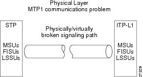
MTP1 standardizes SS7 signaling link physical connectivity. When an MTP1 problem occurs, there is a physical connection break or a virtual break (something that causes the symptoms of a physical connection break, such as no power to a card slot) in the signaling link path. A break is identified when no Message Signaling Unit (MSU), Fill-In Signaling Unit (FISU), or Link Status Signaling Unit (LSSU) traffic can be sent or received over the SS7 link. MTP1 communication problems are normally the result of either a hardware failure, a cabling problem, or a physical interface problem.
Figure B-2 Physical Layer, MTP1 Communication Problems
Resolving MTP1 Communication Problems
If monitoring the SS7 link with a protocol analyzer reveals no MSU, FISU, or LSSU message traffic, complete the following steps:
Step 1
Step 2
Step 3
One SS7 protocol analyzer must be equipped to send/receive SS7 test messages to the Cisco SLT over the V.35 interface, and the other to send/receive messages to the Cisco SLT over the IP interface.

Caution
Step 4
Step 5
MTP2 Communication Problems
The next two sections describe the procedures for identifying and solving MTP2 communication problems.
Identifying MTP2 Communication Problems
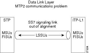
MTP2 standardizes SS7 signaling link alignment. MTP2 communication problems occur when Cisco SLTs cannot establish data link alignment with STPs. When this happens the FISUs and MSUs cease to be transmitted. FISUs and MSUs are replaced by LSSUs whenever an SS7 link has good physical connectivity (MTP1), but cannot align to send and receive either FISU or MSU traffic.
Figure B-3 Data Link Layer, MTP2 Communication Problem
Resolving MTP2 Communication Problems
If monitoring of the SS7 link with a protocol analyzer reveals no MSU or FISU message traffic (only LSSU traffic), complete the following steps:
Step 1
Step 2
One SS7 protocol analyzer must be equipped to send/receive SS7 test messages to the Cisco SLT over the V.35 interface, and the other to send/receive messages to the Cisco SLT over the IP interface.
Step 3
Step 4
If a problem is discovered with the Cisco SLT, replace the unit.
Troubleshooting Cisco SLT to Cisco MGC Communications
Cisco SLTs communicate with Cisco MGCs through a Cisco Catalyst MSR used as a LAN switch. Under normal conditions all Cisco SLTs actively process SS7 message traffic from the STPs. However, only one of the two Cisco MGCs actively processes traffic at any one time. One Cisco MGC always stays in a hot-standby mode while the other actively processes message traffic.
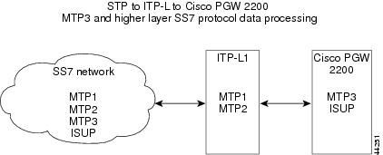
Routing, call control, network management, and all other SS7 application data is framed within SS7 protocol layers MTP3 and higher. The Cisco SLTs, which support MTP1 and MTP2 functionality, pass MTP3 and higher-layer SS7 protocol data between the Cisco MGCs and STP mated pairs.
Cisco SLT to Cisco MGC communication comprises multiple Cisco SLTs, which pass SS7 message traffic on to the Cisco MGCs through the LAN switches. Each STP linkset coming into a Cisco SLT normally has links connected to at least two Cisco SLTs to ensure network survivability.
The Cisco-proprietary Reliable User Datagram Protocol (RUDP) is used for Cisco SLT to Cisco MGC communication. In a fault-tolerant configuration, for example, Ethernet 10BaseT links each Cisco SLT to two LAN switches, and 100BaseT links each LAN switch to both the active Cisco MGC and the standby Cisco MGC.
Identifying MTP3 and Higher Layer Problems
Although the Cisco SLTs normally pass MTP3 and higher-layer data directly to the Cisco MGCs, Cisco SLT hardware could also be the cause of MTP3 and higher layer SS7 communication problems. Cisco SLT-originated MTP3 or higher layer SS7 problems can affect message traffic over a certain link, or just the links that transceive through a certain Cisco SLT.
Cisco SLTs package received SS7 message data into RUDP datagrams that are transmitted through the LAN switches onto the Cisco MGC. This process is reversed (Cisco SLT strips RUDP datagrams) and standard SS7 message framing is added by the Cisco SLTs when the Cisco MGCs send SS7 messages to the Cisco SLTs.
If a tested SS7 link has connectivity (MTP1) and alignment (MTP2), but SS7 error messages are reported by network management tools, then there is probably an MTP3 or higher layer SS7 communication problem. This problem requires testing to verify Cisco SLT operation.
Figure B-4 MTP3 and Higher-Layer SS7 Protocol Processing
Resolving MTP3 and Higher Layer SS7 Communication Problems
Coordinate a signaling link test of the SS7 transceive path within the system, excluding connectivity to distant end SS7 nodes. Use a recommended SS7 protocol analyzer to send SS7 messages to the suspected Cisco SLT while monitoring the output of the Cisco SLT with a recommended protocol analyzer. If no MTP1 (connectivity), MTP2 (link alignment), or MTP3 or higher layer problem is discovered by the test, then the problem probably is not the Cisco SLT under test.
Caution
Cisco MGC and the media gateway.
Identifying Ethernet Connectivity Problems
SS7 message components are Ethernet framed and transceived through one of the Cisco SLT's two Ethernet 10BaseT ports. A physical break or a virtual break will result in a percentage of message traffic not being received along the Cisco MGC path (Cisco SLT-to-LAN switch-to-Cisco MGC). Utilization of a Packet Internet Groper (PING) utility program to perform echo response tests should suffice to identify Ethernet connectivity problems within these components.
Identifying IP Communication Problems
Cisco SLT traffic is routed, rerouted, and, if necessary, retransmitted to the Cisco MGCs through the LAN switches. Monitoring for the following Internet Control Message Protocol (ICMP) error-reporting datagrams will assist in identifying IP communication problems:
•
•
•
•
•
•
•
If IP communication is good, then the RUDP application layer software could be the cause of the problem. Utilizing echo and timestamp request messages and monitoring response messages should be sufficient to identify RUDP/IP/Ethernet communication problems within the system.
Cisco SLT Error Messages
Table B-3 lists the Cisco SLT error messages broadcast by the Cisco MGC.
If you need to contact your technical support representative for assistance, be prepared to provide the Cisco SLT and Cisco MGC debug trace information captured while the problem was occurring. In most cases, the backhaul trace and the LSC trace from the Cisco SLT would be required. If the problem is associated with link alignment, you should also include the IAC trace output. Trace information can help the investigator delineate the problem to the Cisco SLT or to the Cisco MGC.
To enable MTP2 traces, enter the following commands:
debug ss7 mtp2 back channel
debug ss7 mtp2 lsc channel
debug ss7 mtp2 iac channel
To turn debug trace off, enter the command un all
The output from a show version command provides explicit details about the image and branch info. This information tells specifically which branch of code to investigate.
The output from a show run command indicates what Cisco SLT configuration is in use. This is important because many problems can be caused by improper configurations, such as timer durations.
Provide any information from show commands that you used to identify the problem; for example:
show ss7 sm statsInclude any other information that might be useful in understanding or reproducing the problem. This information will help your technical support representative verify the fix.
 Feedback