Front Panel Layout
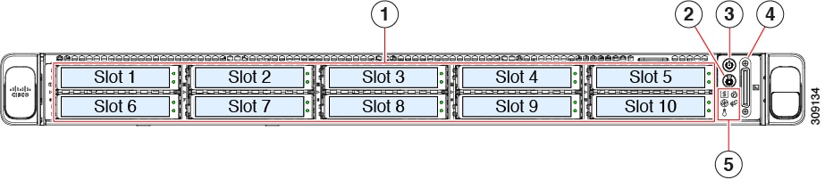
This section details the front panel layout, LEDs and ports.
|
1 |
SED drives (Slot 1 and Slot 2 occupied only) |
||
|
2 |
Unit identification button/LED |
||
|
3 |
Power button/power status LED |
||
|
4 |
KVM connector (used with KVM cable that provides one DB-15 VGA, one DB-9 serial, and two USB 2.0 connectors) |
||
|
5 |
System LED cluster:
|
 Feedback