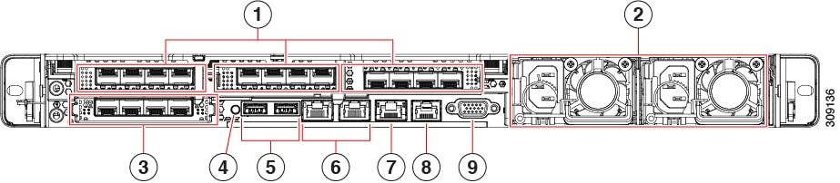
Rear Panel Layout
This section details the rear panel layout, LEDs and ports.
|
1 |
In Riser 1 on the left-hand side, a Low-profile PCIe slot houses two SFP ports:
|
||||
|
2 |
Power supplies PSU 01 and PSU 02. The second power supply provides 1+1 redundancy. |
||||
|
3 |
Modular LAN on Motherboard (mLOM) card slot (not populated). |
||||
|
4 |
System identification button/LED. |
||||
|
5 |
USB 3.0 ports (two). |
||||
|
6 |
Dual 1-Gb/10-Gb Ethernet ports (LAN3 and LAN4):
|
||||
|
7 |
CIMC 1-Gb Ethernet dedicated management port. |
||||
|
8 |
Serial COM port (RJ-45 connector). |
||||
|
9 |
VGA video port (DB-15 connector). |
||||
For more information on the method to configure a Dedicated Management Interface (DMI), see Cisco Expressway Administrator Guide.
 Feedback