Cisco UCS X410c M8 Compute Node Overview
The Cisco UCS X410c M8 Compute Node (UCSX-410C-M8) is a two-slot compute node that supports four CPU sockets for 6th Generation Intel® Xeon® Scalable Processors. Each compute node is exactly four CPUs.
The overall compute node consists of two distinct subnodes, a primary and a secondary.
-
The primary contains two CPUs (1 and 2), two heatsinks, and half of the DIMMs. All additional hardware components and supported functionality are supported through the primary, including the front and rear mezzanine hardware options, rear mezzanine bridge card, front panel, KVM, management console, and status LEDs.
-
The secondary contains two additional CPUs (3 and 4), two heatsinks, and the other half of the DIMMs. The secondary also contains a power adapter, which ensures that the electrical power is shared and distributed between the primary and secondary. The power adapter is not a customer-serviceable part.
Each Cisco UCS X410c M8 compute node supports the following:
-
Up to 16 TB of system memory using 64 DDR5 DIMMs. The DIMMs operate up to 6400 MHz with 1 DPC, and up to 5200 MHz with 2 DPC. Thirty-two DDR5 DIMMs are supported on the primary, and 32 DIMMs are supported on the secondary.
-
Supports 16 DIMMs per CPU, 8 channels per CPU socket, 2 DIMMs per channel. Memory Mirroring and RAS is supported.
-
Supported memory can be populated as 64 GB, 96 GB, 128 GB, or 256 GB DDR5 DIMMs.
-
One front mezzanine module which can support any of the following:
-
A front storage module, which supports multiple different storage device configurations:
-
Compute Pass Through Controller (UCSX-X10C-PT4F-D)
-
All NVMe configuration consisting of up to six U.3 NVMe Gen4 (x4 PCIe) SSDs in slots 1 through 6.
-
-
24G Tri-mode M1 RAID controller (UCSX-RAID-M1L6)
-
A storage configuration consisting of up to six SAS/SATA or U3 NVMe drives is supported in slot 1 through 6. Mixture of RAID creation between SAS and SATA, SAS and U3 NVME, SATA and U3 NVMe are not allowed. U.3 NVMe drives are also supported with an integrated RAID mode as well as Direct attach mode for slot 5 and 6.
-
SAS: 12G, 24G in a x1 config
-
SATA: 6G in a x1 config
-
NVMe: Gen 4 in a x2 config
-
-
-
Pass Through Controller for E3.S drives (UCSX-X10C-PTE3), which supports up to nine hot-pluggable EDSFF E3.S NVMe drives.
-
The Compute Node front panel has a flexible configuration through the front mezzanine module option you ordered. The following options are supported: as documented in
-
Compute Node front panel with SAS/SATA/NVMe Drives
-
Compute Node front panel with U.3 NVMe Drives
-
Compute Node Font Panel with E3.S NVMe Drives.
For additional information, see Drive Front Panels.
-
For additional information, see Front Mezzanine Options.
-
-
1 modular LAN on motherboard (mLOM) module or virtual interface card (VIC) supporting a maximum of 200G of aggregate traffic, 100G to each fabric, through a Cisco 5th Gen 100G mLOM/VIC. For more information, see mLOM and Rear Mezzanine Slot Support.
-
A boot-optimized mini-storage module. Two versions of mini-storage exist:
-
One version supports up to two M.2 SATA drives of up to 960GB each. This version supports an optional hardware RAID controller (RAID1).
-
One version supports up to two M.2 NVMe drives of up to 960GB each that are directly attached to CPU 1. This version does not support an optional RAID controller.
Two options of mini-storage exist, one supporting up to two M.2 SATA drives with a MSTOR-RAID controller (UCSX-M2I-HWRD-FPS), and one supporting up to two M.2 NVMe drives direct attached to CPU1 through a Passthrough controller (UCSX-M2-PT-FPN).
-
-
Local console connectivity through a USB Type-C connector.
-
Up to 4 UCS X410c M8 compute nodes can be installed in a Cisco UCS X9508 modular system.
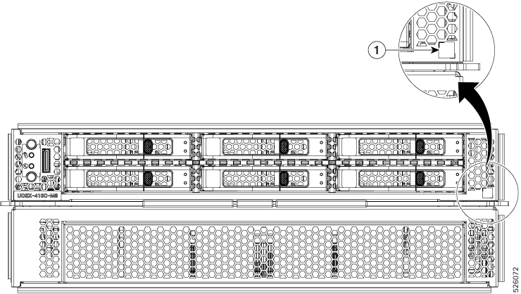
Compute Node Identification
Each Cisco UCS X410c M8 compute node features a node identification tag at the lower right corner of the primary node.
-
The Cisco product identifier (PID) or virtual identifier (VID)
-
The product serial number
The product identification tag applies to the entire compute node, both the primary and secondary.
You will find it helpful to scan the QR code so that the information is available if you need to contact Cisco personnel.
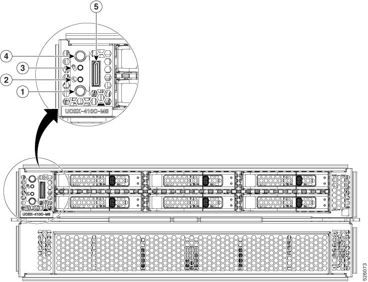
Compute Node Front Panel
The Cisco UCS X410c M8 front panel contains system LEDs that provide visual indicators for how the overall compute node is operating. An external connector is also supported.
Compute Node Front Panel
|
1 |
Power LED and Power Switch The LED provides a visual indicator about whether the compute node is on or off.
The switch is a push button that can power off or power on the compute node. See Front Panel Buttons. |
2 |
System Health LED A multifunction LED that indicates the state of the compute node.
|
|
3 |
System Activity LED The LED blinks to show whether data or network traffic is written to or read from the compute node. If no traffic is detected, the LED is dark. The LED is updated every 10 seconds. |
4 |
Locator LED/Switch The LED provides a visual indicator that glows solid blue to identify a specific compute node. The switch is a push button that toggles the Indicator LED on or off. See Front Panel Buttons. |
|
5 |
External Connector (Oculink) that supports local console functionality. |
Front Panel Buttons
The front panel has some buttons that are also LEDs. See Compute Node Front Panel.
-
The front panel Power button is a multi-function button that controls system power for the compute node.
-
Immediate power up: Quickly pressing and releasing the button, but not holding it down, causes a powered down compute node to power up.
-
Immediate power down: Pressing the button and holding it down 7 seconds or longer before releasing it causes a powered-up compute node to immediately power down.
-
Graceful power down: Quickly pressing and releasing the button, but not holding it down, causes a powered-up compute node to power down in an orderly fashion.
-
-
The front panel Locator button is a toggle that controls the Locator LED. Quickly pressing the button, but not holding it down, toggles the locator LED on (when it glows a steady blue) or off (when it is dark). The LED can also be dark if the compute node is not receiving power.
For more information, see Interpreting LEDs.
Drive Bays
Each Cisco UCS X410c M8 compute node has a front mezzanine slot that can support local storage drives of different types and quantities of 2.5-inch SAS, SATA, or U.3 drives and E3.S drives. Drive blank panels (UCSC-BBLKD-M8 or UCSC-E3SIT-F=) must cover all empty drive bays as appropriate.
For front a mezzanine module that supports SAS, SATA, or U.3 drives, the drive bays are numbered sequentially from 1 through 6 as shown.
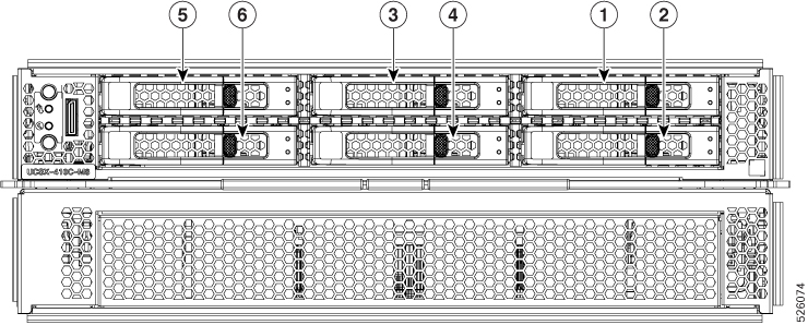
For front a mezzanine module that supports E3.S EDSFF NVMe drives, the drive bays are numbered sequentially from 1 through 9 as shown.

Drive Front Panels
The front drives are installed in the front mezzanine slot of the compute node. SAS/SATA and NVMe drives are supported.
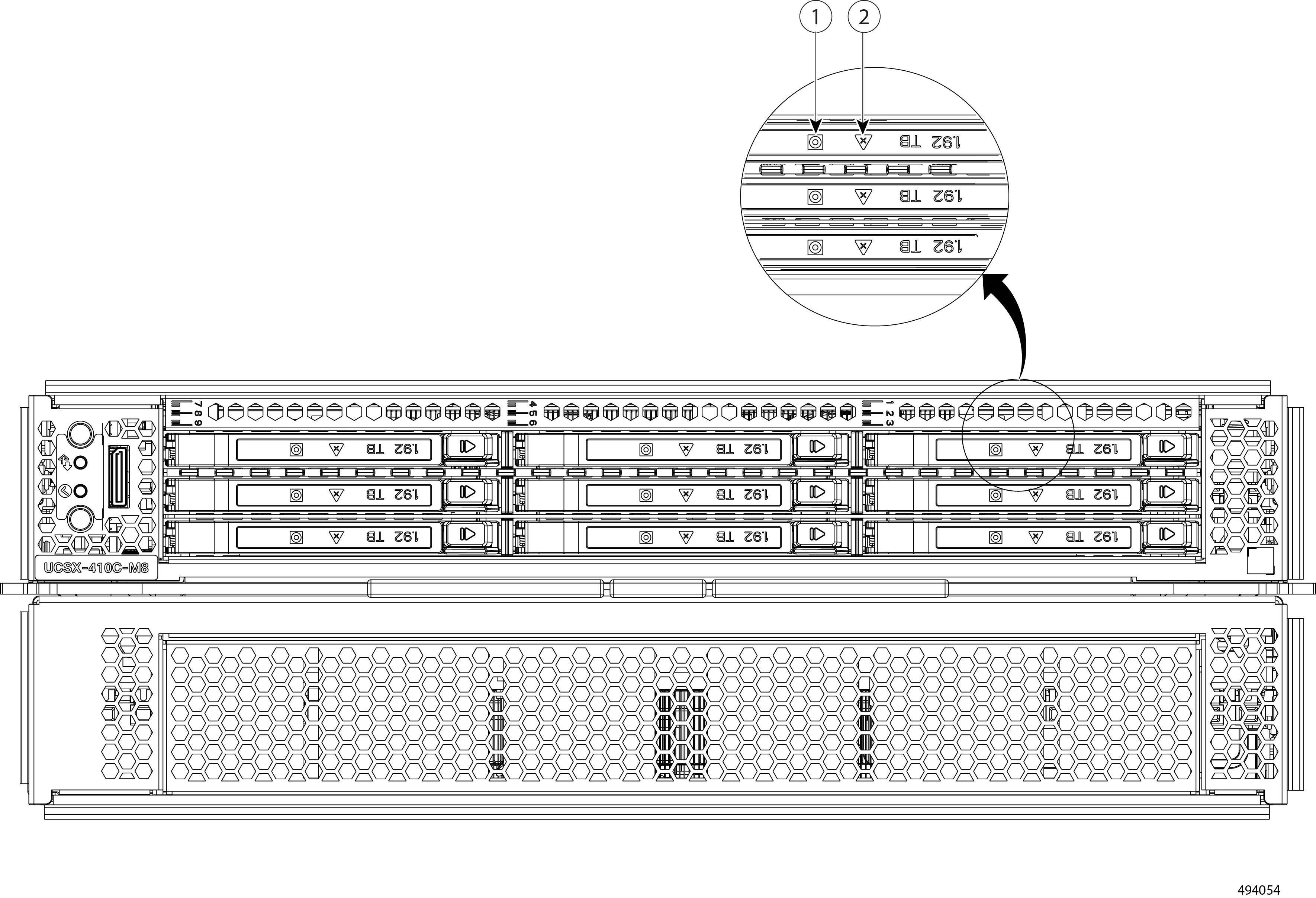
Compute Node Front Panel with SAS/SATA/NVMe Drives
The compute node front panel contains the front mezzanine module, which can support a maximum of six SAS/SATA or U.3 NVMe drives. The drives have additional LEDs that provide visual indicators about each drive's status.

|
1 |
Drive Health LED |
2 |
Drive Activity LED |
Compute Node Front Panel with U.3 NVMe Drives
The compute node front panel contains the front mezzanine module, which can support a maximum of six U.3 NVMe drives.
Compute Node Front Panel with E3.S NVMe Drives
The compute node front panel contains the front mezzanine module, which can support a maximum of nine E3.S NVMe PCIe Gen 5 1.92 TB drives in pass-through mode.
|
1 |
Drive Activity LED |
2 |
Drive Health LED |


 Feedback