Cisco UCS C880A M8 Rack Server Troubleshooting Guide
Available Languages
Refer to the table below for changes made on this version of the Cisco UCS C880A M8 Rack Server Troubleshooting Guide.
| Date |
Version |
Updates |
| Jan 16, 2026 |
V1.0 |
First release |
Table of Contents
Create USB Drives from the Released ISO
Troubleshooting Hardware Issues
Server Management Software Issues
BMC Time Collect and Configure
BMC IP Source and IP Address Configuration
Troubleshooting Operating System Issues
How to Install the Operation System using Virtual Media - Ubuntu 24.04
Error occur after a BIOS setting is changed
Failure occurs during ROM flash via BMC web
See the SERR or PERR error on SEL
PCI device not found / found but not plugged
Appendix A: The way to output BIOS log
| Specification |
Value |
|
| GPU |
● Supported NV GPU: DGX B300 2.3TB SXM7 with GPU BB
● GPU-GPU Interconnect: NVIDIA
® NVLink™ with NVSwitch™
● CPU-GPU Interconnect: 8x PCIe Gen5 x16
|
|
| CPU |
2-sockets, Intel Xeon 6 2.4G 350W Processor, 64 Cores/CPU, PCIeG5 |
2-sockets, Intel Xeon 6 2.3G 350W Processor, 64 Cores/CPU, PCIeG5 |
| Power (TDP) |
350W per processor |
350W per processor |
| L3 Cache |
336 MB |
336 MB |
| System Memory |
32x DDR5 DIMM slots (8 channels/CPU, 2x Slot/Channel)
● Up to 6400MT/s
● Up to 32x DDR5 128GB for DIMM Air cooling
|
|
| Expansion Slots |
2x PCIe Gen5 x16 BF3 150W CEM board (CPU) |
|
| LAN |
2x GbE Management LAN |
|
| Management |
DC-SCM with AST2600 |
|
| Storage |
● Up to 8x hot-swap E1.S
● Up to 2x M.2
|
|
| System Cooling |
● 20x 8080 Dual-Rotor
|
|
| System BIOS |
● AMI
® BIOS
|
|
| System Software |
● Ubuntu (operating system)
|
|
| I/O Ports |
● 1x USB3.0 type A
● 1x USB2.0 Micro USB for Debug
● 1x Mini DP
● 2x 1Gbs RJ45
● 1x PWR Button
● 1x UID Button
● 1x Reset Button
|
|
| System Form Factor |
● 10U Rackmount
● H:17.39" (441.75mm) x W:17.6" (447mm) x D:31.49" (800mm)
|
|
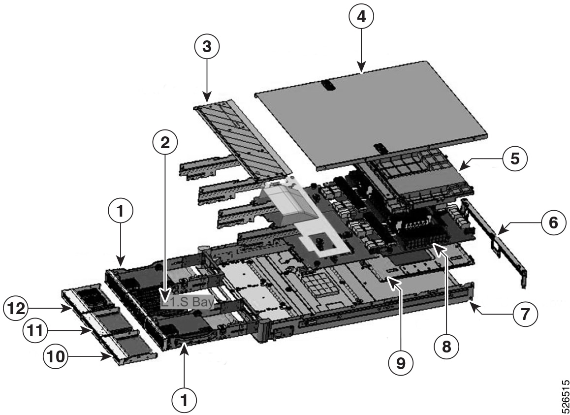
| Item |
Description |
| 1 |
BF3 Bay |
| 2 |
E1.S Bay |
| 3 |
Front Cover |
| 4 |
CPU Sled Top Cover |
| 5 |
Air Baffle |
| 6 |
Linking Bar |
| 7 |
CPU Sled Lower Case |
| 8 |
CPU Board |
| 9 |
Switch Board |
| 10 |
DCSCM Bay |
| 11 |
Blank Bay |
| 12 |
M.2 Bay |
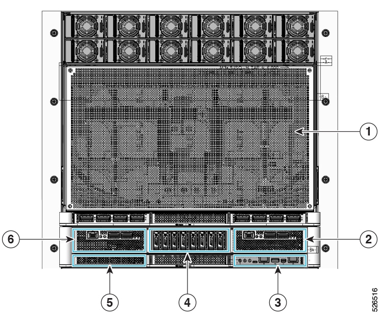
| Item |
Description |
| 1 |
GPU Sled |
| 2 |
IO Bay 1 |
| 3 |
DC-SCM Module |
| 4 |
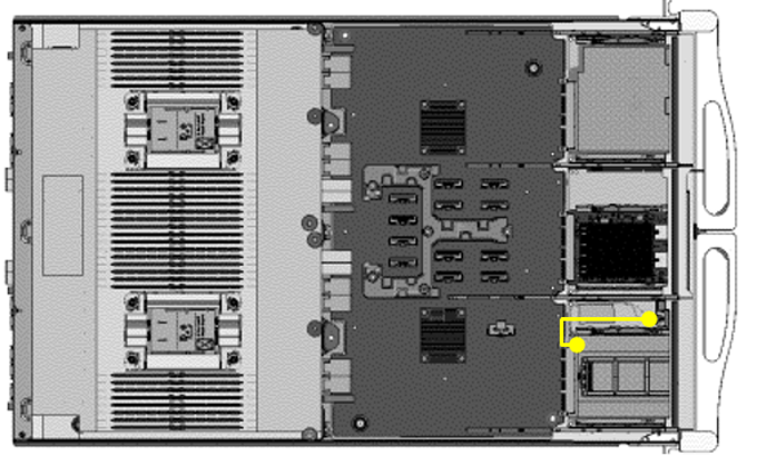
Local Node Storage (1, 2, 3, 4, 5, 6, 7, 8) |
| 5 |
Boot Drive Bay |
| 6 |
IO Bay 2 |
| Term |
Definition |
| CPU |
Central Processing Unit. Common reference to both CISC (complex instruction set computer) and RISC (reduced instruction set computer) processors |
| FHHL |
PCIe card form factor, Full Height Half Length |
| OSFP |
Octal Small Form-factor Pluggable |
| NIC |
Network Interface Card |
| NVMe |
Non-Volatile Memory Express |
| OCP |
Open Compute Project |
| PCIe |
Peripheral Component Interconnect Express. Refers to a communication like defined within PCISIG standards body. |
| BMC |
Baseboard Management Controller |
| FRU |
Field Replace Unit |
| DCSCM |
Datacenter Secure control Module Specification |
| IPMI |
Intelligent Platform Management Interface |
| S0 |
S-State 0. System power on. |
| S5 |
S-State 5. System power off. |
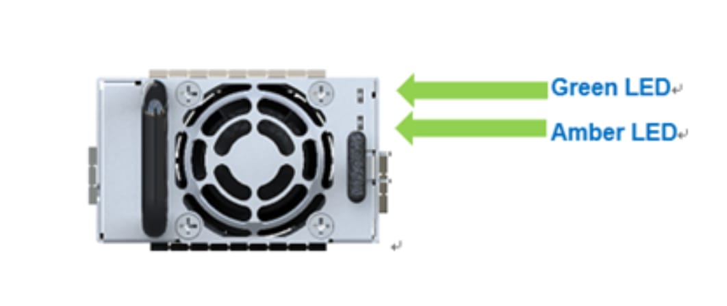
| Indicator Mode |
Condition |
| Off |
No AC power input or PSU failed |
| Green |
4Hz blink: Ready to turn on and awaiting the sync Start signal. |
| Solid on: 50V output is ON |
|
| Amber |
4Hz blink: Boot loading or Firmware update (with output on) |
| Solid on: Primary/Secondary/Fan/boot loading Failure or loss of 50V output by fault event |
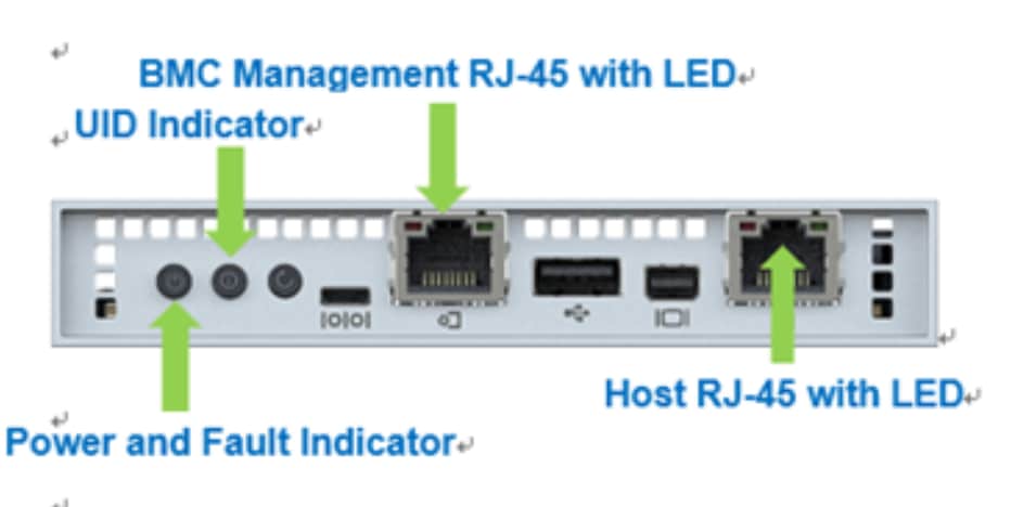
| Indicator Code |
Condition |
| Power and Fault Indicator |
|
| Off |
Power Off |
| Green Fast Blink |
Pre-S5 |
| Green Slow Blink |
S5 |
| Green Solid On |
S0 |
| Amber Solid On |
Warning |
| ID Indicator |
|
| Off |
UID is off |
| Blue Solid On |
UID is on |
| BMC Management RJ-45 with LED |
|
| Left & Right - off |
No connection |
| Left – Amber Blinking |
Link and Active on network |
| Right – Amber |
Link and run in 1Gbps |
| Right – Green |
Link and run in 100Mbps |
| Host RJ-45 with LED |
|
| Left & Right - off |
No connection |
| Left – Amber Blinking |
Link and Active on network |
| Right – Amber |
Link and run in 1Gbps |
| Right – Green |
Link and run in 100Mbps |
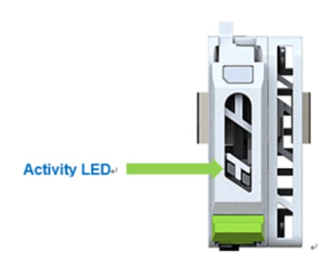
| Indicator |
Color |
Blinking Pattern |
Behavior for Device |
| Activity LED |
OFF |
OFF |
Drive not present |
| Green |
Solid ON |
Drive present but no activity |
|
| Green |
Blinking 4Hz |
Drive Present, I/O Activity |
The Self-Diagnostic Test is used to perform function coverage testing. Running on Linux, it is a UI framework to merge/involve different test diagnostic programs including Open-Source tools (included BSD/GPL v2.0 license), Vendor Tools/Drivers, and some diagnostic tools from ODM.
The user can utilize selftest.py to merge various diagnostic utilities, packages, and scripts for conducting function testing. ODM can set up and build a package that includes selftest.py and diagnostic utilities for customers to perform interaction testing.
Create USB Drives from the Released ISO
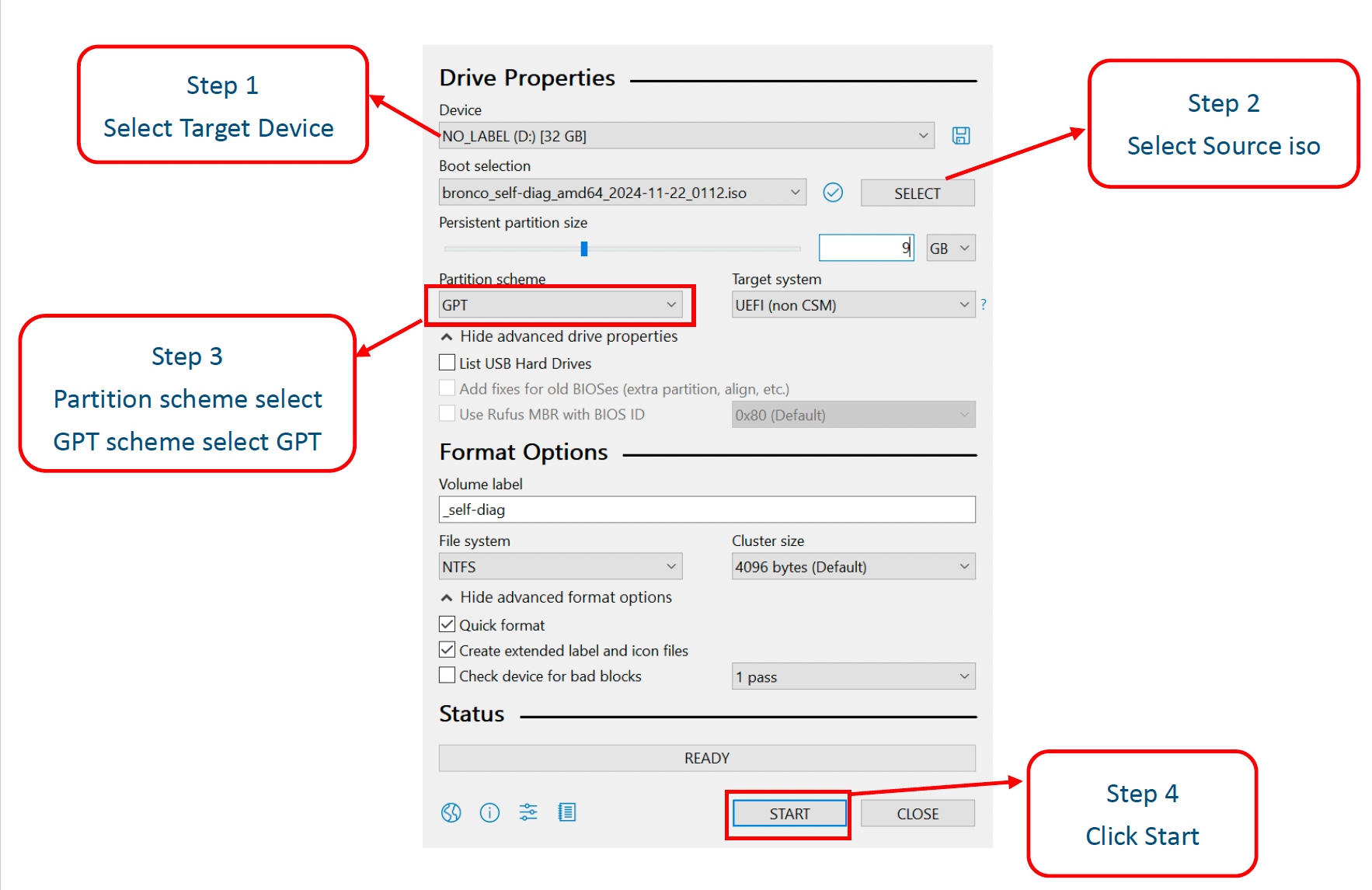
Creating a bootable USB drive from an ISO image can be achieved through a variety of methods, depending on your operating system. We recommend using software tools to create a USB drive, such as Rufus.
We need two partitions: the first partition to write the ISO image, and the second partition to save log data.
Requirements
Rufus 4.5
Write the ISO Image to the Target Device
Step 1. Select target Device (Your USB KEY > 32GB).
Step 2. Select source iso.
Step 3. Partition scheme select GPT.
Step 4. Click Start.
The program is executed with this test command by manual
Execute Self-Diagnostic Test command follow step as below:
Step 1. Left click Terminal.
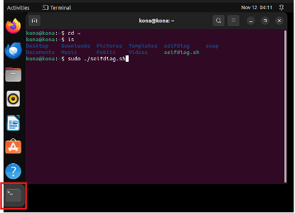 |
Step 2. Type “cd /” and press Enter → Type “ls” and press Enter (check selfdiag.sh exists) → Type “sudo ./selfdiag.sh” and press Enter.
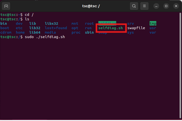
Step 3. 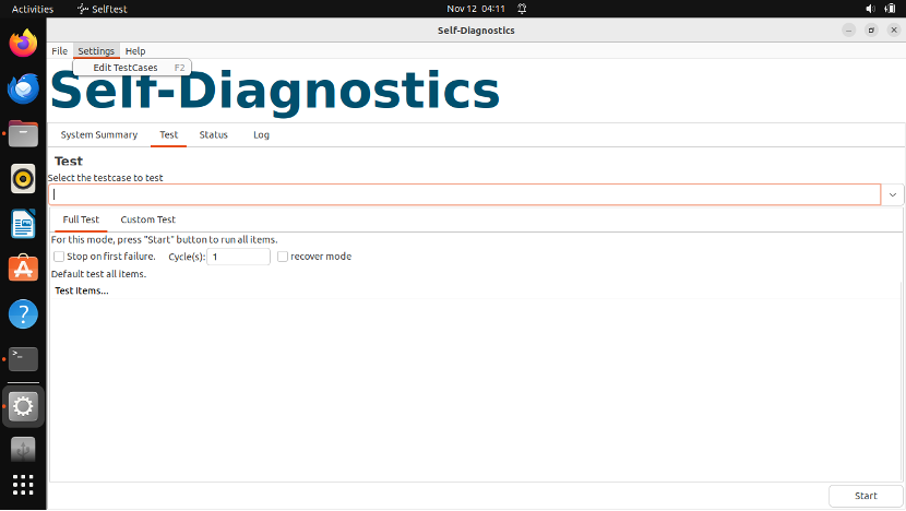 Successfully executed program.
PS. If the system logs out automatically. You can use the following information to log in again.
User: The account is the Name you entered during installation.
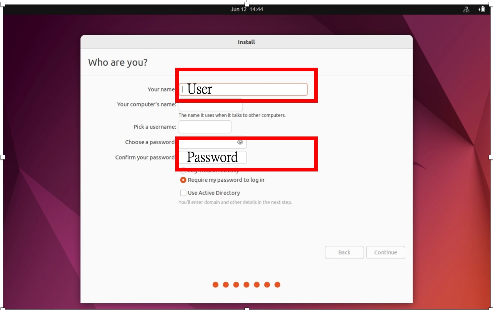 Password: The Password is you entered during installation.
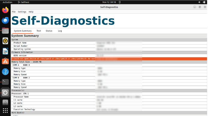
Main window
System Summary
It shows your “system”, “memory”, “CPU”, “Hard Disk”
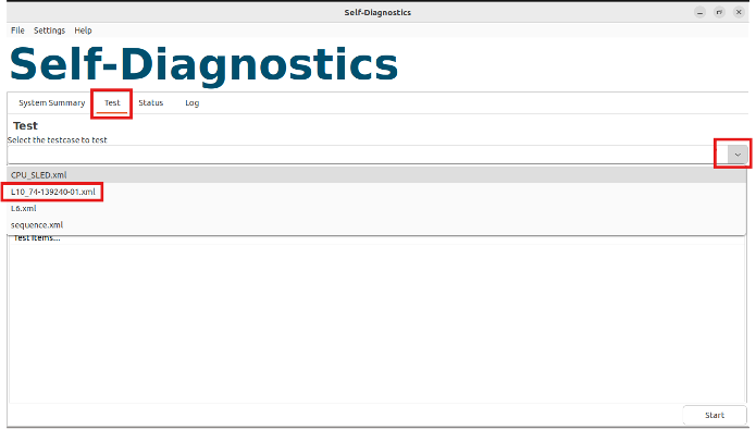
Test
Follow steps as below:
1. Left click “Test” → Select the testcase to test → select which SKU you want to test
Main window
System Summary
It shows your “system”, “memory”, “CPU”, “Hard Disk”.
Test
Follow steps as below:
1. Left click “Test” → Select the testcase to test → select which SKU you want to test.
2. Press Start button to start test during testing
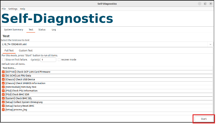 |
Remark: Perform all test items which defined in “L10_74-XXXXXX.xml…”
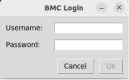
Test Item: BMC Login Info
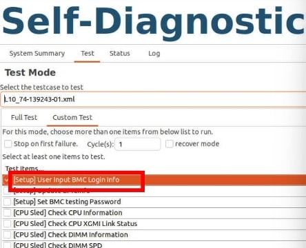
This test case will prompt a window prompting the user to input the BMC ID and password, which is used for redfish command related test case.
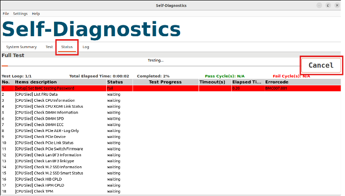
Test Status
Check test status and you can also press Cancel button to stop test during testing.
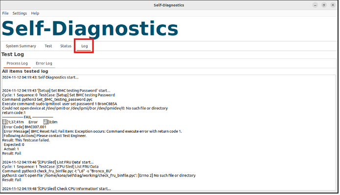
Test Log
Log – Login for unlocking Log function
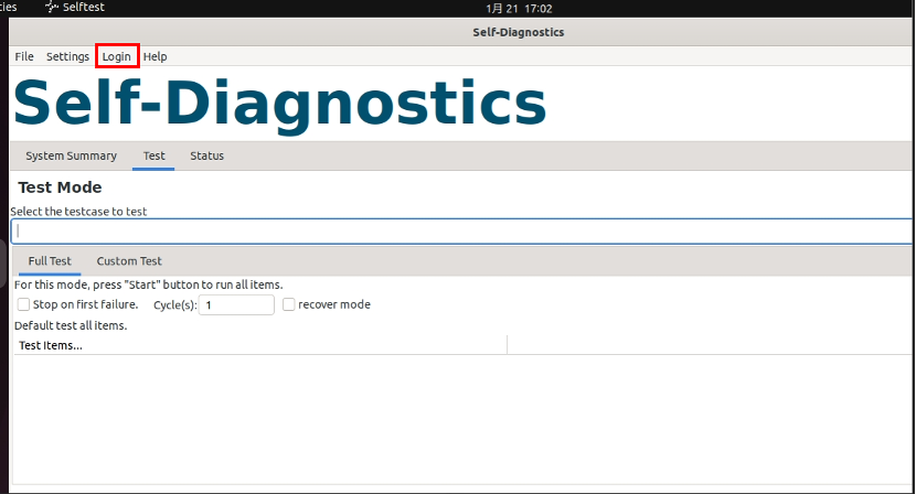
Log – Input Username and Password for Login
Username: admin
Password: superuser
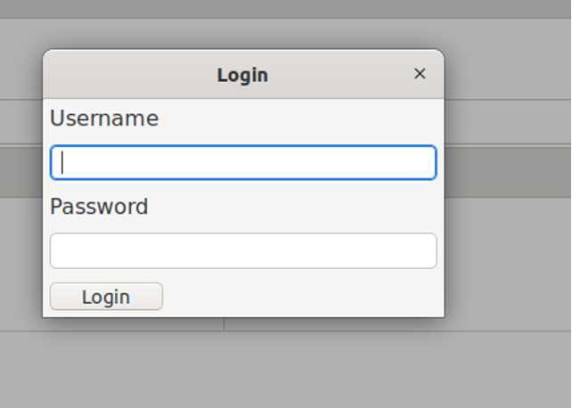
Unzip password: superuser
![]()
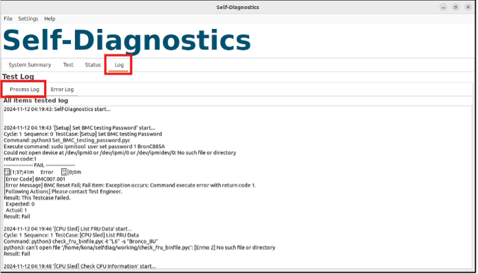
Log - Process Log
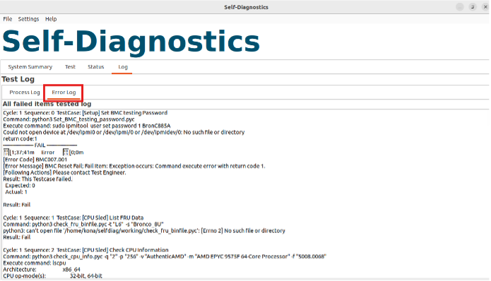
Log - Error Log
You can initially judge the possible problematic part through the text in [] in front of each test item. For detailed Fail items, please refer to the Test Log to DEBUG.
Troubleshooting Hardware Issues
G3 to S5
After providing AC power, you can refer to postcode debug LED on MB and check if LED has been lighting on or not.
If yes, please refer to table 1. and check the corresponding post code number.
If not, please re-program MB CPLD FW and check if the scenario can be solved or not.
| Postcode |
Description |
| 01 |
CPU0 Not Present |
| 02 |
CPU Mismatch |
| 03 |
G3SoftEn |
| 04 |
CEC2_RST_MON_AP_RST_REQ_N_FPGA |
| 05 |
PWRGD_PVCC3V3_AUX_CPU0 |
| 06 |
PWRGD_P1V1_AUX |
| 07 |
PWRGD_PVCCFA_EHV_CPU0_PWRGD |
| 08 |
PWRGD_PVNN_MAIN_CPU0_PWRGD |
| 09 |
FM_HPM_STBY_RST (BMC Ready) |
| 10 |
PWRGD_CPU0_AUX_PWRGD |
| 11 |
FM_CPU0_GLB_RST_WARN |
| 14 |
FM_CPU0_SLPS5 |
Table 1. G3àS5 Postcode
FPGA postcode error code check
When system post hangs, please note the number on postcode debug LED and refer to Table 2. below to check the root cause.
| Postcode |
Description |
| 51 |
PWRGD_P1V1_AUX |
| 52 |
PWRGD_PVCCFA_EHV_CPU0_PWRGD |
| 53 |
PWRGD_PVNN_MAIN_CPU0_PWRGD |
| 61 |
PWRGD_P12V_VRM1 |
| 62 |
PWRGD_P12V_VRM2 |
| 63 |
PWRGD_P3V3_PWRGD |
| 64 |
P1V8_SW01_PGD |
| 65 |
PG_P1V25_SW01 |
| 66 |
PWRGD_P0V8_SW01 |
| 71 |
PWRGD_PVCCD0_HV_CPU0_PWRGD |
| 72 |
PWRGD_PVCCD1_HV_CPU0_PWRGD |
| 73 |
iPWRGD_PVCCFA_EHV_FIVRA_CPU0_PWRGD |
| 74 |
PWRGD_PVCCINFAON_CPU0_PWRGD |
| 75 |
PWRGD_PVCCIN_CPU0_PWRGD |
| 81 |
PWRGD_PVCC3V3_AUX_CPU1 |
| 82 |
PWRGD_PVCCFA_EHV_CPU1_PWRGD |
| 83 |
PWRGD_PVNN_MAIN_CPU1_PWRGD |
| 84 |
PWRGD_PVCCD0_HV_CPU1_PWRGD |
| 85 |
PWRGD_PVCCD1_HV_CPU1_PWRGD |
| 86 |
PWRGD_PVCCFA_EHV_FIVRA_CPU1_PWRGD |
| 87 |
PWRGD_PVCCINFAON_CPU1_PWRGD |
| 88 |
PWRGD_PVCCIN_CPU1_PWRGD |
| 91 |
H_CPU0_THERMTRIP_N |
| 92 |
H_CPU1_THERMTRIP_N |
| 93 |
H_CPU0_MEMTRIP_N |
| 94 |
H_CPU1_MEMTRIP_N |
| 95 |
CPU0_DIMM_MEM_FLT |
| 96 |
CPU1_DIMM_MEM_FLT |
Table 2. Error code
S5 to S0(POST)
Please observe the postcode to understand the current boot progress and status.
| Postcode |
Description |
| 14 |
FM_CPU0_SLPS5 |
| 15 |
FM_CPU0_S5_PWR_RETAINED |
| 16 |
FM_CPU0_SLPS4 |
| 17 |
FM_CPU0_SLPS3 |
| 18 |
BP_MID_SYSTEM_READY |
| 20 |
FM_P12V_VRM_PG (include PDB_12V_PGD) |
| 21 |
PWRGD_P3V3_PWRGD |
| 22 |
PWRGD_P0V8_SW01 |
| 23 |
PWRGD_PVCC3V3_AUX_CPU1 |
| 24 |
PWRGD_PVCCFA_EHV_CPU1 |
| 25 |
PWRGD_PVNN_MAIN_CPU1 |
| 26 |
PWRGD_CPU1_AUX_PWRGD |
| 27 |
PWRGD_PVCCDx_HV_CPUx |
| 28 |
PWRGD_PVCCFA_EHV_FIVRA_CPUx |
| 29 |
PWRGD_PVCCINFAON_CPUx |
| 30 |
PWRGD_PVCCIN_CPUx |
| 31 |
PWRGD_CPUx_S0_PWROK |
| 34 |
FM_CPUx_REFCLK_RDY |
| 35 |
PWRGD_CPU0_CPUPWRGD_FPGA |
| 36 |
H_CPUx_THERMTRIP_N or RST_CPU0_PLTRST_SYNC_N |
| 37 |
wRST_CPUx_N |
| 38 |
PWRGD_CHx_CPUx_DIMMx |
| 39 |
PWRGD_DRAMPWRGD_CPUx |
| 40 |
M_CPUx_RESET_N |
| 41 |
M_CPUx_FPGA_RESET_N |
Table 3. S5àS0 Postcode
Troubleshooting under OS issue
Loss PCIE Device Check
Prerequisite
PCIE Device does not detect under OS.
Troubleshooting steps:
1. Under OS and execute the command to check which device lost & corresponding slot.
Location
● Check PCIe Tree and device address: lspci -tv | less
● Check which slot ID cannot recognize:
lspci -v | grep -i “slot:” |sort “
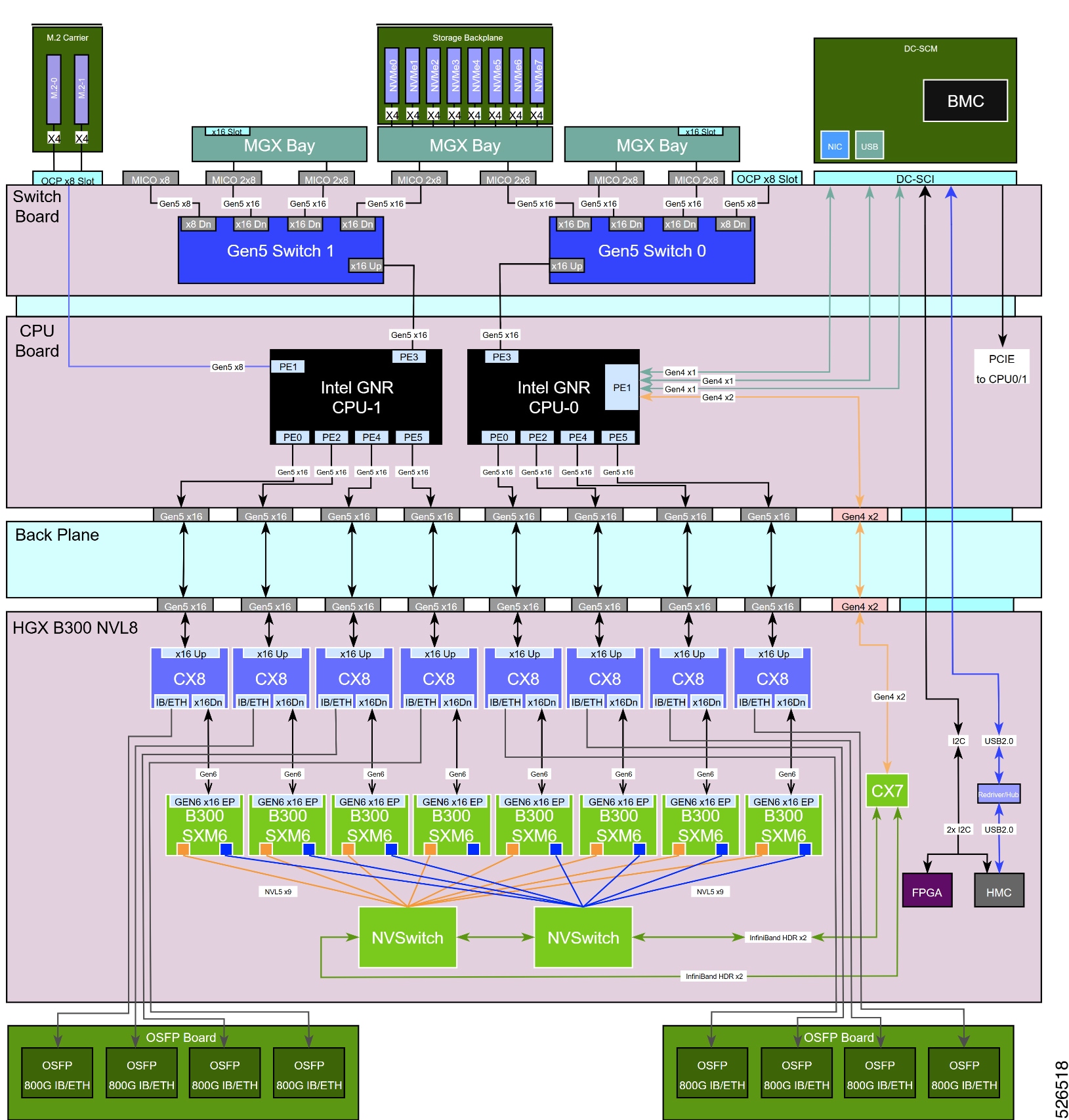
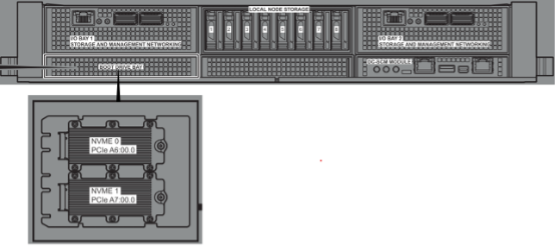
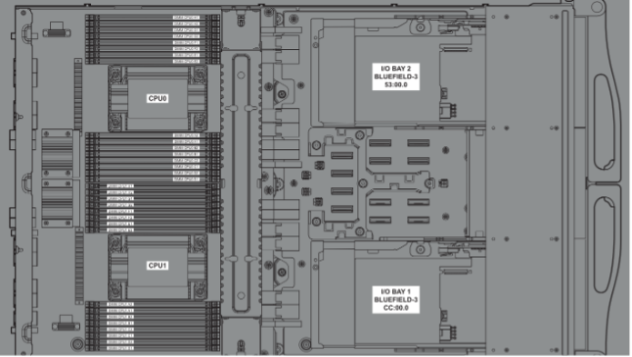
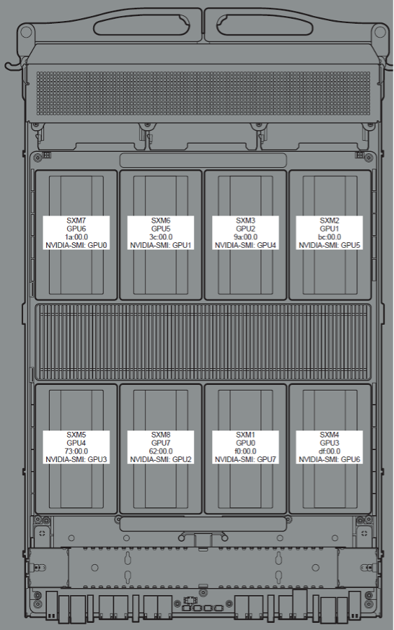
2. After get the lost slot location, apply below system PCIE topology Mapping table to check the path of lost device. (Figure 4-1 to 4-3 and Table 4-1 to 4-3)
3. Referring to the system cable routing to check the connection between cable/board and the device through the cable ID.
Multiple devices cannot be detected due to cable faults or poor plugging Therefore, we recommend applying HW Check first.
 |
| Device |
Bus No. |
Board |
| USB |
26:00.0 |
DC-SCM Module |
| I210 |
2A:00.0 |
DC-SCM Module |
| GPU CX7 |
27:00.0 |
B300 Baseboard |
| E1.S-5 |
CD:00.0 |
Local Node Storage |
| E1.S-6 |
CE:00.0 |
Local Node Storage |
| E1.S-7 |
CF:00.0 |
Local Node Storage |
| E1.S-8 |
D0:00.0 |
Local Node Storage |
| E1.S-4 |
4D:00.0 |
Local Node Storage |
| E1.S-3 |
4E:00.0 |
Local Node Storage |
| E1.S-2 |
4F:00.0 |
Local Node Storage |
| E1.S-1 |
50:00.0 |
Local Node Storage |
| Riser-M2-2 |
A7:00.0 |
Boot Drive Bay |
| Riser-M2-1 |
A6:00.0 |
Boot Drive Bay |
Table 4. PCIE Bus Mapping Table
 |
| Device |
Bus No. |
Board |
| SWITCH1 |
C8:00.0 |
CPU Sled |
| SWITCH0 |
48:00.0 |
CPU Sled |
| PcieRiser-1 (BF3) |
53:00.0 |
CPU Sled |
| PcieRiser-2 (BF3) |
CC:00.0 |
CPU Sled |
Table 5. CPU Sled Mapping Table
| Device |
Bus No. |
Board |
| CX8-7 |
17:00.0 |
B300 Baseboard |
| CX8-6 |
39:00.0 |
B300 Baseboard |
| CX8-8 |
5F:00.0 |
B300 Baseboard |
| CX8-5 |
10:00.0 |
B300 Baseboard |
| CX8-3 |
37:00.0 |
B300 Baseboard |
| CX8-2 |
B9:00.0 |
B300 Baseboard |
| CX8-4 |
DC:00.0 |
B300 Baseboard |
| CX8-1 |
ED:00.0 |
B300 Baseboard |
| SXM7 |
1A:00.0 |
B300 Baseboard |
| SXM6 |
3C:00.0 |
B300 Baseboard |
| SXM8 |
02:00.0 |
B300 Baseboard |
| SXM5 |
13:00.0 |
B300 Baseboard |
| SXM3 |
9A:00.0 |
B300 Baseboard |
| SXM2 |
BC:00.0 |
B300 Baseboard |
| SXM4 |
DF:00.0 |
B300 Baseboard |
| SXM1 |
F0:00.0 |
B300 Baseboard |
Table 6. B300 Baseboard Mapping Table
● GPU Mapping Table
| nvidia-smi (inband) |
HGX_GPU (Redfish) |
HGX_GPU_SXM |
| GPU0 |
GPU6 |
SXM7 |
| GPU1 |
GPU5 |
SXM6 |
| GPU2 |
GPU7 |
SXM8 |
| GPU3 |
GPU4 |
SXM5 |
| GPU4 |
GPU2 |
SXM3 |
| GPU5 |
GPU1 |
SXM2 |
| GPU6 |
GPU3 |
SXM4 |
| GPU7 |
GPU0 |
SXM1 |
● CPU SLED Upper Layer with E1.S & Riser Cage Modules
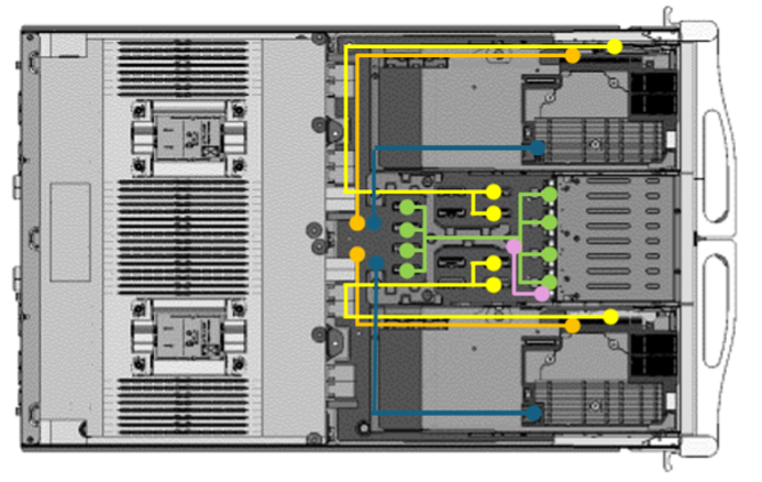
| Cable Description |
Color |
Q’ty |
| DA-CEM Riser x16 Cable: SW(J10MCIO&J9MCIO) to PCIe Riser board SW(J4MCIO&J3MCIO) to PCIe Riser board |
2 |
|
| BF3 Power Cable: SW(CNPWR4) to BF3-L SW(CNPWR5) to BF3-R |
2 |
|
| DA-CEM RISER X16 POWER CABLE: SW(CNPWR7) to PCIe Riser board SW(CNPWR6) to PCIe Riser board |
2 |
|
| E1.S BP MCIO Cable BZR: SW(J2MCIO) to E1.S Board(JMCIO4) SW(J1MCIO) to E1.S Board(JMCIO3) SW(J8MCIO) to E1.S Board(JMCIO2) SW(J7MCIO) to E1.S Board(JMCIO1) |
4 |
|
| E1.S BP Power Cable BZR: SW(CNPWR3) to E1.S Board(JPW1) |
|
1 |
● CPU SLED Lower Layer with M.2, OCP & DCSCM Modules
| Cable Description |
Color |
Q’ty |
| Ambient Sensor Cable: M.2 Board(CNAMB1) to Front Side |
|
1 |
Cannot detect single E1.S device
1. Re-plug the E1.S.
2. If you still cannot read the device, change the new E1.S SSD.
3. 3. If still cannot read, please re-plug the E1.S Cable Module and make sure the cable and connector are no bent pins/ pollution.(*1)
4. 4. If there are no bent pins or pollution, try to change a new E1.S Module.(*1)
Note: *1 Please refer to User Manual – Chapter 3 Assembly SOP.
Server Management Software Issues
BMC Firmware Revision
Redfish:
curl -sku {user}:{password} -X GET https://{BMC IP}/redfish/v1/Managers/BMC
Property Name: FirmwareVersion
Description: Represents the revision of the BMC
This figure provides a reference example for the BMC Firmware Revision results.
![]()
IPMI:
In-Band:
ipmitool mc info
Out-of-Band:
ipmitool -I lanplus -H {BMC IP} -U {User} -P {Password} mc info
This figure provides a reference example for the BMC Firmware Revision results.
![]()
BIOS Firmware Revision
Redfish:
curl -sku {user}:{password} -X GET https://{BMC IP}/redfish/v1/Systems/DGX
Property Name: BiosVersion
Description: Represents the revision of the BIOS
This figure provides a reference example for the BIOS Firmware Revision results.
![]()
DC-SCM CPLD Firmware Revision
Redfish:
curl -sku {user}:{password} -X GET https://{BMC IP}/redfish/v1/UpdateService/FirmwareInventory/CPLDDCSM_0
Property Name: Version
Description: Represents the revision of the DC-SCM CPLD
This figure provides a reference example for the DC-SCM CPLD Firmware Revision results.
![]()
MB CPLD Firmware Revision
Redfish:
curl -sku {user}:{password} -X GET https://{BMC IP}/redfish/v1/UpdateService/FirmwareInventory/CPLDMB_0
Property Name: Version
Description: Represents the revision of the MB CPLD
This figure provides a reference example for the MB CPLD Firmware Revision results.
![]()
E1.S CPLD Firmware Revision
Redfish:
curl -sku {user}:{password} -X GET https://{BMC IP}/redfish/v1/UpdateService/FirmwareInventory/CPLDE1SBP_0
Property Name: Version
Description: Represents the revision of the E1.S CPLD
This figure provides a reference example for the E1.S CPLD Firmware Revision results.
![]()
Backplane CPLD Firmware Revision
Redfish:
curl -sku {user}:{password} -X GET https://{BMC IP}/redfish/v1/UpdateService/FirmwareInventory/CPLDBACK_0
Property Name: Version
Description: Represents the revision of the Backplane CPLD
This figure provides a reference example for the BackPlane CPLD Firmware Revision results.
![]()
PCIe Switch Firmware Revision
Redfish:
curl -sku {user}:{password} -X GET https://{BMC IP}/redfish/v1/UpdateService/FirmwareInventory/PCIeSwitch_0
curl -sku {user}:{password} -X GET https://{BMC IP}/redfish/v1/UpdateService/FirmwareInventory/PCIeSwitch_1
Property Name: Version
Description: Represents the revision of the PCIe Switch
This figure provides a reference example for the PCIe Switch 0 Firmware Revision results.
![]()
This figure provides a reference example for the PCIe Switch 1 Firmware Revision results.
![]()
GPU Firmware Revision
Redfish:
curl -sku {user}:{password} -X GET https://{BMC IP}/redfish/v1/UpdateService/FirmwareInventory/{GPU_Instance}
GPU_Instance:
HGX_FW_BMC_0,
HGX_FW_ConnectX_0 ~ HGX_FW_ConnectX_7,
HGX_FW_ConnectX_SMA_0 ~ HGX_FW_ConnectX_SMA_3,
HGX_FW_ERoT_BMC_0,
HGX_FW_ERoT_FPGA_0,
HGX_FW_ERoT_NVLinkManagementNIC_0,
HGX_FW_ERoT_NVSwitch_0, ~ HGX_FW_ERoT_NVSwitch_1,
HGX_FW_FPGA_0,
HGX_FW_GPU_0 ~ HGX_FW_GPU_7,
HGX_FW_NVLinkManagementNIC_0,
HGX_FW_NVSwitch_0 ~ HGX_FW_NVSwitch_1,
HGX_FW_SXM_SMA_0 ~ HGX_FW_SXM_SMA_7,
HGX_InfoROM_GPU_0 ~ HGX_InfoROM_GPU_7
This figure provides a reference example for the HGX_FW_BMC_0 Firmware Revision results.
![]()
Power Status
Redfish:
curl -sku {user}:{password} -X GET https://{BMC IP}/redfish/v1/Systems/DGX
Property Name: PowerState
Description: Represents the power status of the system
This figure provides a reference example for the power status.
![]()
IPMI:
In-Band:
ipmitool power status
Out-of-Band:
ipmitool -I lanplus -H {BMC IP} -U {User} -P {Password} power status
This figure provides a reference example for the power status.
![]()
Power On
Redfish:
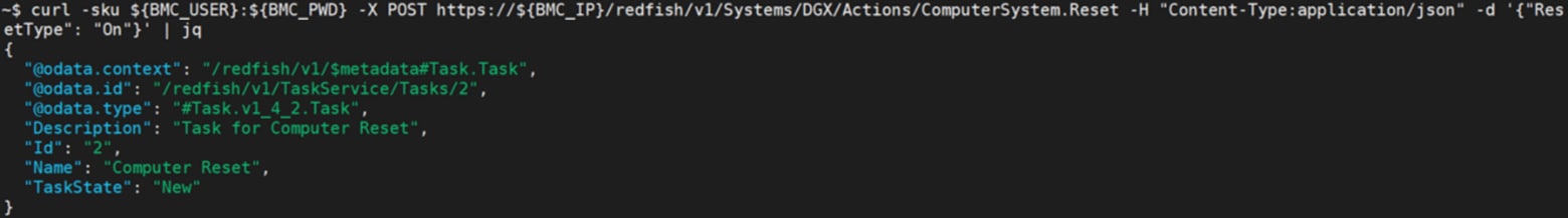
curl -sku {user}:{password} -X POST https://{BMC IP}/redfish/v1/Systems/{System_Instance}/Actions/ComputerSystem.Reset -H "Content-Type:application/json" -d '{"ResetType": "On"}'
This figure provides a reference example for executing power-on.
 |
IPMI:
In-Band:
ipmitool power on
Out-of-Band:
ipmitool -I lanplus -H {BMC IP} -U {User} -P {Password} power on
This figure provides a reference example for executing power-on.
![]()
Power Off
Redfish:
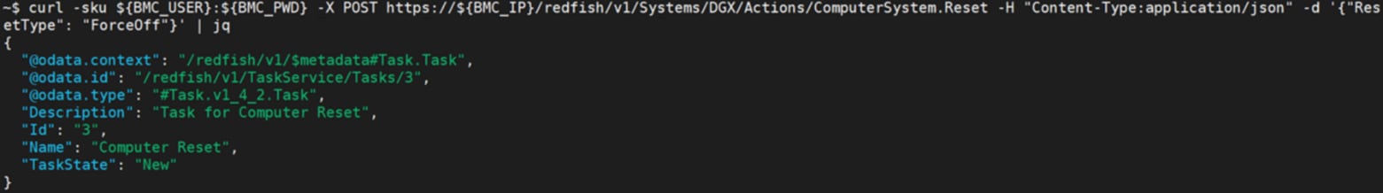
curl -sku {user}:{password} -X POST https://{BMC IP}/redfish/v1/Systems/{System_Instance}/Actions/ComputerSystem.Reset -H "Content-Type:application/json" -d '{"ResetType": "ForceOff"}'
This figure provides a reference example for executing power-off.
 |
IPMI:
In-Band:
ipmitool power off
Out-of-Band:
ipmitool -I lanplus -H {BMC IP} -U {User} -P {Password} power off
This figure provides a reference example for executing power-off.
![]()
Power Cycle
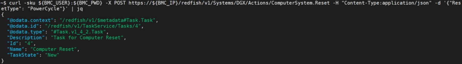
Redfish:
curl -sku {user}:{password} -X POST https://{BMC IP}/redfish/v1/Systems/{System_Instance}/Actions/ComputerSystem.Reset -H "Content-
Type:application/json" -d '{"ResetType": "PowerCycle"}'
This figure provides a reference example for executing power-cycle.
IPMI:
In-Band:
ipmitool power cycle
Out-of-Band:
ipmitool -I lanplus -H {BMC IP} -U {User} -P {Password} power cycle
This figure provides a reference example for executing power-cycle.
AC Cycle
IPMI:
In-Band:
ipmitool raw 0x3c 0x99
Out-of-Band:
ipmitool -I lanplus -H {BMC IP} -U {User} -P {Password} 0x3c 0x99
This figure provides a reference example for executing ac-cycle.
IPMI:
In-Band:
ipmitool raw 0x30 0x20 0x01 {PWM}
Out-of-Band:
ipmitool -I lanplus -H {BMC IP} -U {User} -P {Password} raw 0x30 0x20 0x01 {PWM}
Note: The PWM range 0x14 to 0x64 in hexadecimal represents the range 20 to 100 in decimal.
This figure provides a reference example for executing manual fan control.
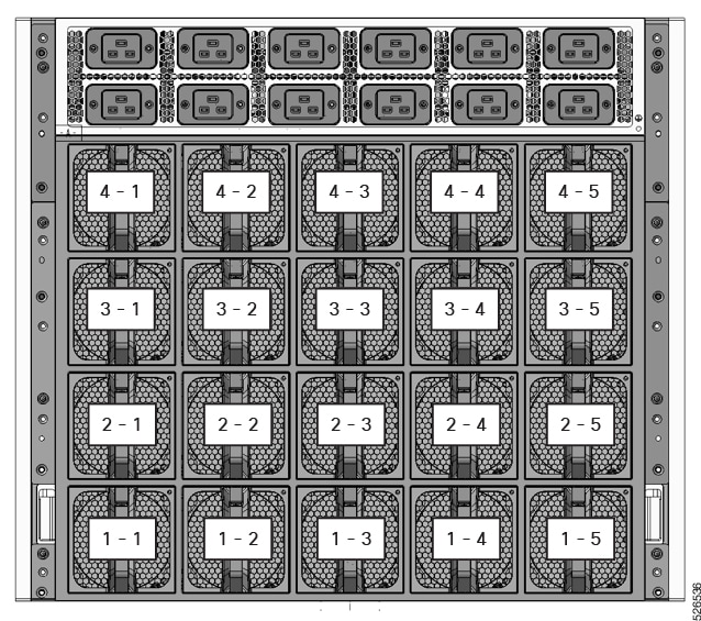 FAN Configurations Diagram
BMC Time Collect and Configure
BMC Date & Time Collection
Redfish:
curl -sku {user}:{password} -X GET https://{BMC IP}/redfish/v1/Managers/BMC
Property Name: DateTime
Description: Represents the current date and time of the BMC.
This figure provides a reference example for date and time of the BMC.
![]()
IPMI:
In-Band:
ipmitool sel time get
Out-of-Band:
ipmitool -I lanplus -H {BMC IP} -U {User} -P {Password} sel time get
This figure provides a reference example for date and time of the BMC.
![]()
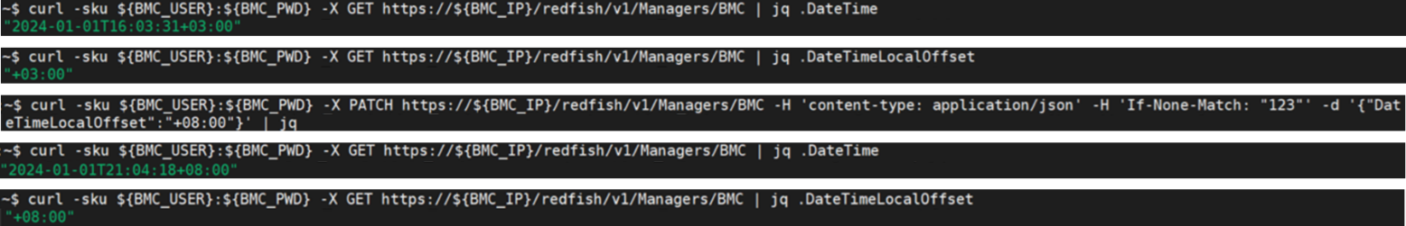
BMC Date & Time Configure
Redfish:
1. Disable NTP
curl -sku {user}:{password} -X PATCH https://{BMC IP}/redfish/v1/Managers/BMC/NetworkProtocol -H 'content-type: application/json' -H 'If-None-Match: "123"' -d '{"NTP":{"ProtocolEnabled":false}}'
2. Configure BMC Date & Time
curl -sku {user}:{password} -X PATCH https://{BMC IP}/redfish/v1/Managers/BMC -H 'content-type: application/json' -d '{"DateTime": "yyyy-mm-ddThh:mm:ss+00:00"}'
This figure provides a reference example for executing BMC Date & Time Configuration.

IPMI:
In-Band:
ipmitool sel time set "mm/dd/yyyy hh:mm:ss"
Out-of-Band:
ipmitool -I lanplus -H {BMC IP} -U {User} -P {Password} sel time set "mm/dd/yyyy hh:mm:ss"
This figure provides a reference example for executing BMC Date & Time Configuration.
![]()
BMC Time Zone Collection
Redfish:
curl -sku {user}:{password} -X GET https://{BMC IP}/redfish/v1/Managers/BMC
Property Name: DateTimeLocalOffset
Description: Represents the current time zone of the BMC.
This figure provides a reference example for the time zone of the BMC.
![]()
BMC Time Zone Configure
Redfish:
1. Disable NTP
curl -sku {user}:{password} -X PATCH https://{BMC IP}/redfish/v1/Managers/BMC/NetworkProtocol -H 'content-type: application/json' -H 'If-None-Match: "123"' -d '{"NTP":{"ProtocolEnabled":false}}'
2. Configure BMC Date & Time
curl -sku {user}:{password} -X PATCH https://{BMC IP}/redfish/v1/Managers/BMC -H 'content-type: application/json' -d '{"DateTime": "yyyy-mm-ddThh:mm:ss+00:00"}'
This figure provides a reference example for executing BMC time zone Configuration.
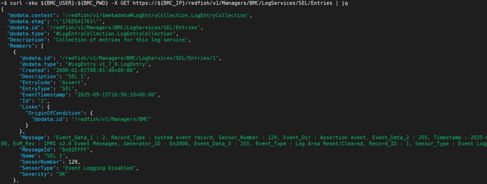
BMC SEL Collection
Redfish:
curl -sku {user}:{password} -X GET https://{BMC IP}/redfish/v1/Managers/BMC/LogServices/SEL/Entries
This figure provides a reference example for BMC SEL collection.
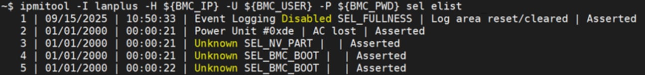
IPMI:
In-Band:
ipmitool sel list
or
ipmitool sel elist
Out-of-Band:
ipmitool -I lanplus -H {BMC IP} -U {User} -P {Password} sel list
or
ipmitool -I lanplus -H {BMC IP} -U {User} -P {Password} sel elist
This figure provides a reference example for BMC SEL collection.
BMC SEL Clear
Redfish:
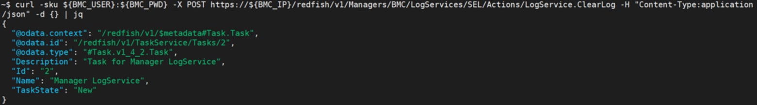
curl -sku {user}:{password} -X POST https://{BMC IP}/redfish/v1/Managers/BMC/LogServices/SEL/Actions/LogService.ClearLog -H "Content-Type:application/json" -d {}
This figure provides a reference example for executing BMC SEL clear.
IPMI:
In-Band:
ipmitool sel clear
Out-of-Band:
ipmitool -I lanplus -H {BMC IP} -U {User} -P {Password} sel clear
This figure provides a reference example for executing BMC SEL clear.
![]()
These IDs are used to access and retrieve FRU information.
| FRU Items |
FRU ID |
FRU Items |
FRU ID |
FRU Items |
FRU ID |
| BACK FRU |
#0 |
SWBD FRU |
#4 |
HMC FRU |
#8 |
| MB FRU |
#1 |
DCSCM FRU |
#5 |
|
|
| PDB FRU |
#2 |
E1S FRU |
#6 |
|
|
| HGX FRU |
#3 |
M2 Carrier FRU |
#7 |
|
|
FRU Read
IPMI:
In-Band:
ipmitool fru print {FRU ID}
Out-of-Band:
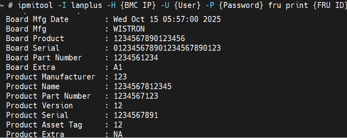
ipmitool -I lanplus -H {BMC IP} -U {User} -P {Password} fru print {FRU ID}
This figure provides a reference example for BMC FRU collection.
FRU Write
In-Band:
ipmitool fru write {FRU ID} {FRU bin file}
Out-of-Band:
ipmitool -I lanplus -H {BMC IP} -U {User} -P {Password} fru write {FRU ID} {FRU bin file}
This figure provides a reference example for executing BMC FRU write.

User Collection
Redfish:
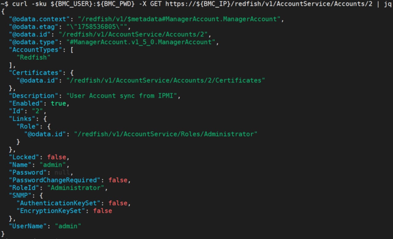
curl -sku {user}:{password} -X GET https://{BMC IP}/redfish/v1/AccountService/Accounts/{Account ID}
This figure provides a reference example for collecting BMC user account.
Add User
Redfish:
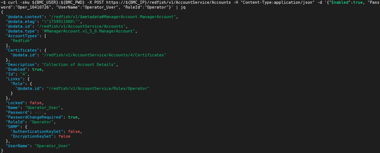
curl -sku {user}:{password} -X POST https://{BMC IP}/redfish/v1/AccountService/Accounts -H "Content-Type:application/json" -d '{"Enabled": {User Access}, "Password": "{Password}", "UserName": "{Username}", "RoleId": "{Privilege}"}'
Username: The username for the account.
Password: The password for this account
Privilege: The role for this account. Value: Administrator, Operator, ReadOnly.
User Access: It indicates whether an account is enabled. If `true`, the account is enabled and the user can log in. If `false`, the account is disabled and, in the future, the user cannot log in
This figure provides a reference example for creating BMC user account.
User Configuration
Redfish:
curl -sku {user}:{password} -X PATCH https://{BMC IP}/redfish/v1/AccountService/Accounts/{Account_Instance} -H "Content-Type:application/json" -H 'If-Match:*' -d '{"{Property}": "{Value}"}'
Property:
Password: Password to be modified
RoleId: RoleId to be disabled or enabled
Enabled: It indicates whether an account is enabled.
This figure provides a reference example for modifying BMC user account setting.
![]()
Delete User
Redfish:
curl -sku {user}:{password} -X DELETE https://{BMC IP}/redfish/v1/AccountService/Accounts/{Account_Instance} -H "Content-Type:application/json" -H 'If-Match:*'
This figure provides a reference example for deleting BMC user.
![]()
Redfish:
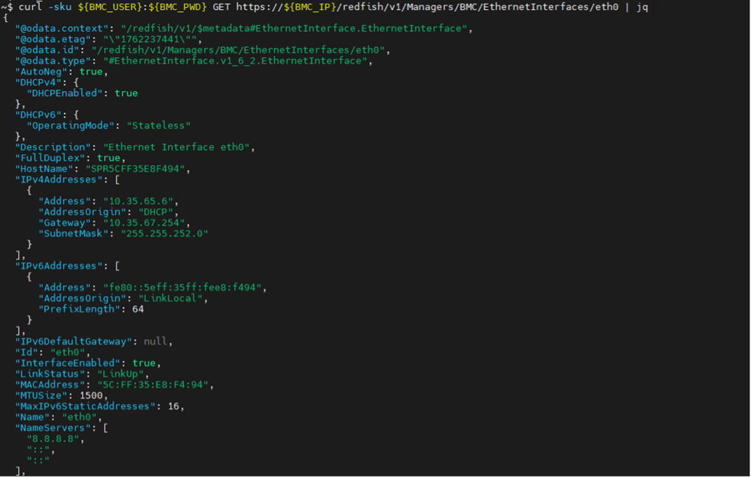
curl -sku {user}:{password} -X GET https://{BMC IP}/redfish/v1/Managers/BMC/EthernetInterfaces/eth0
This figure provides a reference example for BMC Network collection.
BMC IP Source and IP Address Configuration
Redfish:
curl -sku {user}:{password} -X PATCH https://{BMC IP}/redfish/v1/Managers/BMC/EthernetInterfaces/eth0 -H 'Content-Type: application/json' -H 'If-Match:*' -d '{"DHCPv4": {"DHCPEnabled": false},"IPv4StaticAddresses": [{"Address": "'{New BMC IP}'","Gateway": "{GATEWAY}","SubnetMask": "{SUBNETMASK}"}]
}'
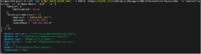 This figure provides a reference example for executing change IP source to 'static' and change IP address.
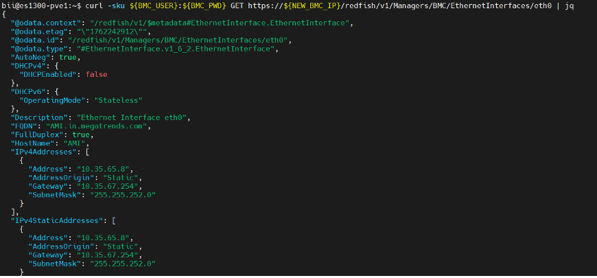
After changing IP source and changing IP address.
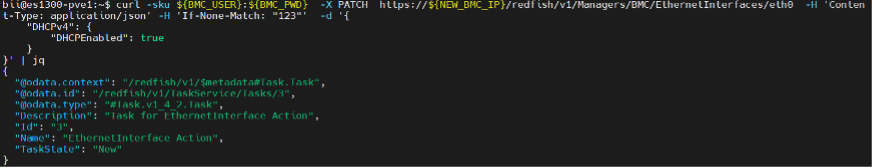
● Configure IP source to DHCP
Redfish:
curl -sku {user}:{password} -X PATCH https:// {BMC IP}/redfish/v1/Managers/BMC/EthernetInterfaces/eth0 -H 'Content-Type: application/json' -H 'If-Match:*' -d '{"DHCPv4":{"DHCPEnabled": true}}'
This figure provides a reference example for executing change IP source to 'DHCP'.
 |
Redfish:
curl -sku {user}:{password} -X PATCH https:// {BMC IP}/redfish/v1/Managers/BMC/EthernetInterfaces/eth0 -H 'content-type: application/json' -H 'If-Match:*' -d '{"FQDN":"{New_Hostname}.in.megatrends.com","HostName": "{New_Hostname}"}'
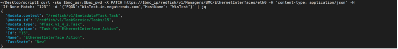 This figure provides a reference example for executing change hostname.
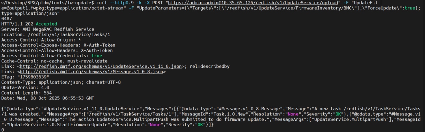
BMC Firmware Update
● Redfish
curl -g --http0.9 -ku {user}:{password} -X POST "https://{BMC IP}/redfish/v1/UpdateService/upload" -F "UpdateFile=@{Firmware Image Path};type=application/octet-stream" -F 'UpdateParameters={"Targets":["/redfish/v1/UpdateService/FirmwareInventory/BMC"],"ForceUpdate":true};type=application/json'
Note: The firmware image must be in the .fwpkg format.
This figure provides a reference example for executing BMC firmware update.
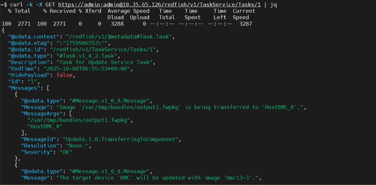
Monitoring BMC Firmware Update Progress:
curl -ku {user}:{password} -X GET https://{BMC IP}/redfish/v1/TaskService/Tasks/{Task ID}
Note: The Task ID can be retrieved from the 'Location' field in the response after executing the BMC firmware update.
This figure provides a reference example for checking BMC firmware update progress.
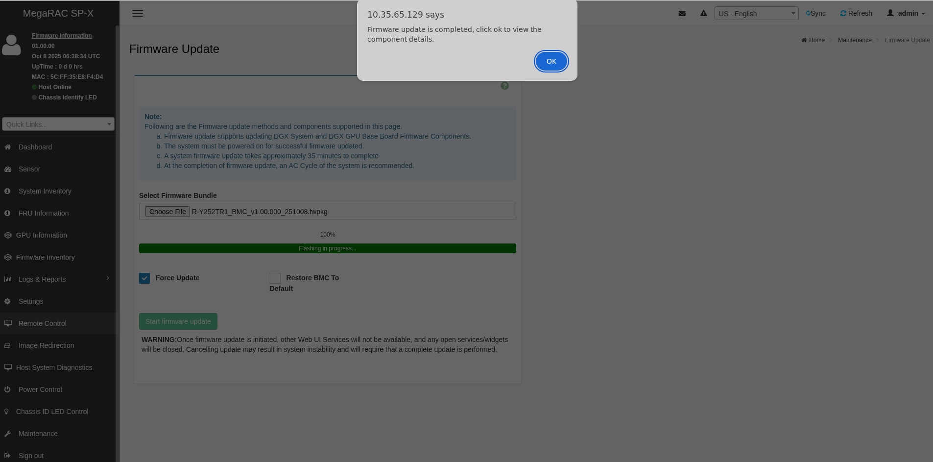
● Web UI
Please log in to the BMC web and go to the Maintenance > Firmware Update.
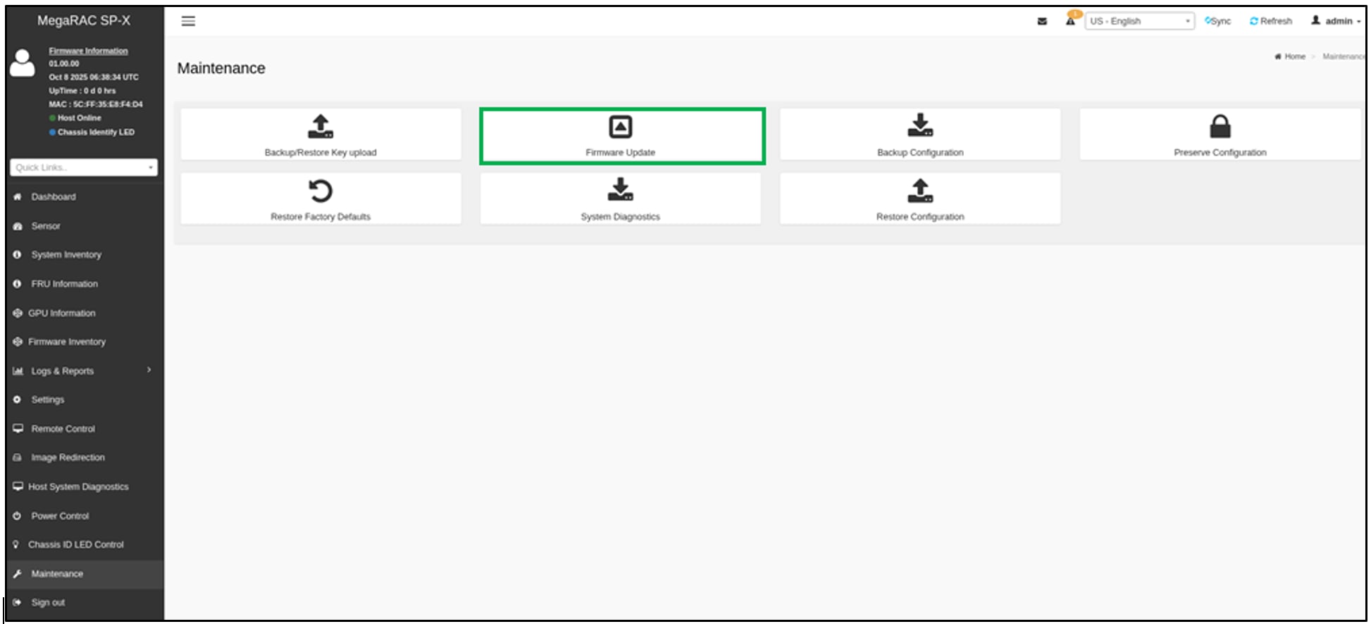
Click "Choose File" to select the BMC Firmware Image, check "Force Update".
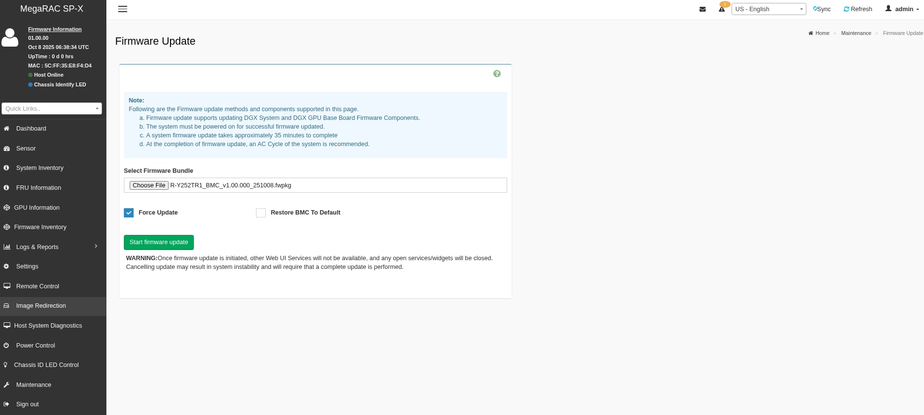
Click 'Start firmware update' to begin the BMC firmware update process. Once the update is complete, a message stating 'Firmware update is completed' will appear, and the BMC will automatically reboot.
BIOS Firmware Update
Web UI
Perform the following:
1. Login BMC Web UI.
2. Go to Maintenance > Firmware Update.
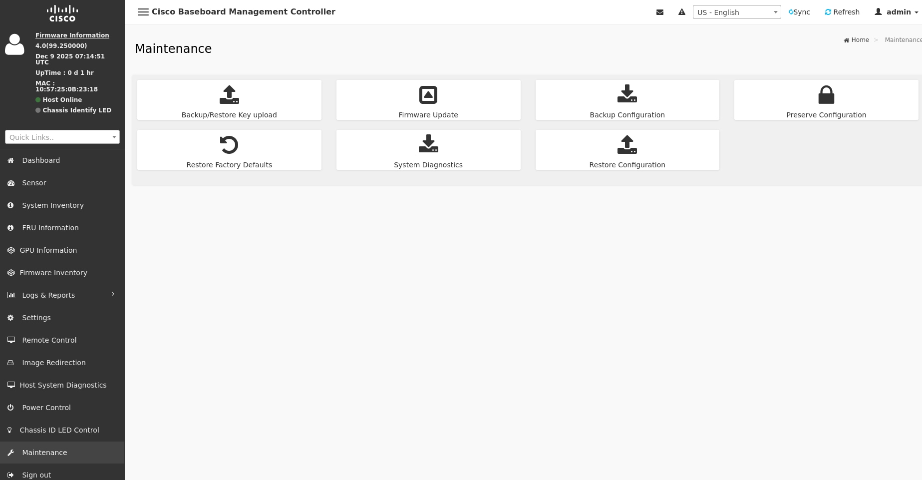
3. Select the BIOS firmware image and tick "Force Update".
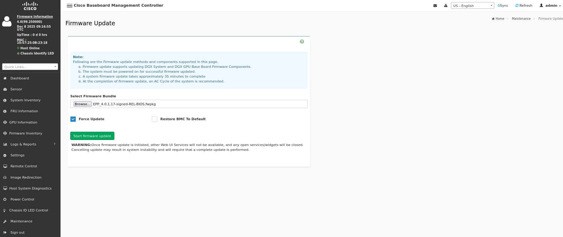
4. Click Start firmware update to begin the BIOS firmware update process.
1. Follow the instructions below to execute the BIOS firmware update.
curl --http1.0 -k -X POST --user <Account>:<Password> -H 'Content-Type:multipart/form-data' --insecure https://<BMC IP>/redfish/v1/UpdateService/upload -F 'UpdateFile=@<bios_image.fwpkg>' -F 'UpdateParameters={"Targets":{}};type=application/json' | jq
Note: The firmware image must be in the .fwpkg format
2. Follow the instructions below to check the BIOS firmware update process.
curl --http1.0 -k -X GET --user <Account>:<Password> -H 'Content-Type:multipart/form-data' --insecure https://<BMC IP>/redfish/v1/TaskService/Tasks/<Task Id> | jq
DC-SCM CPLD Firmware Update
Redfish:
curl -g --http0.9 -ku {user}:{password} -X POST "https://{BMC IP}/redfish/v1/UpdateService/upload" -F "UpdateFile=@{Firmware Image Path};type=application/octet-stream" -F 'UpdateParameters={"Targets":["/redfish/v1/UpdateService/FirmwareInventory/ CPLDDCSM_0"],"ForceUpdate":true};type=application/json'
Note: The firmware image must be in the .fwpkg format.
Monitoring DC-SCM CPLD Firmware Update Progress:
curl -ku {user}:{password} -X GET https://{BMC IP}/redfish/v1/TaskService/Tasks/{Task ID}
Note: The Task ID can be retrieved from the 'Location' field in the response after executing the DCSCM CPLD firmware update.
● Web UI
Refer to Section WebUI Update Method and select DC-SCM CPLD Firmware Image.
MB CPLD Firmware Update
Redfish:
curl -g --http0.9 -ku {user}:{password} -X POST "https://{BMC IP}/redfish/v1/UpdateService/upload" -F "UpdateFile=@{Firmware Image Path};type=application/octet-stream" -F 'UpdateParameters={"Targets":["/redfish/v1/UpdateService/FirmwareInventory/ CPLDMB_0"],"ForceUpdate":true};type=application/json'
Note: The firmware image must be in the .fwpkg format.
Monitoring MB CPLD Firmware Update Progress:
curl -ku {user}:{password} -X GET https://{BMC IP}/redfish/v1/TaskService/Tasks/{Task ID}
Note: The Task ID can be retrieved from the 'Location' field in the response after executing the MB CPLD firmware update.
● Web UI
Refer to WebUI Update Method and select MB CPLD Firmware Image.
E1.S CPLD Firmware Update
Redfish:
curl -g --http0.9 -ku {user}:{password} -X POST "https://{BMC IP}/redfish/v1/UpdateService/upload" -F "UpdateFile=@{Firmware Image Path};type=application/octet-stream" -F 'UpdateParameters={"Targets":["/redfish/v1/UpdateService/FirmwareInventory/ CPLDE1SBP_0"],"ForceUpdate":true};type=application/json'
Note: The firmware image must be in the .fwpkg format.
Monitoring E1.S CPLD Firmware Update Progress:
curl -ku {user}:{password} -X GET https://{BMC IP}/redfish/v1/TaskService/Tasks/{Task ID}
Note: The Task ID can be retrieved from the 'Location' field in the response after executing the E1.S CPLD firmware update.
● Web UI
Refer to Section WebUI Update Method and select E1.S CPLD Firmware Image.
BackPlane CPLD Firmware Update
Redfish:
curl -g --http0.9 -ku {user}:{password} -X POST "https://{BMC IP}/redfish/v1/UpdateService/upload" -F "UpdateFile=@{Firmware Image Path};type=application/octet-stream" -F 'UpdateParameters={"Targets":["/redfish/v1/UpdateService/FirmwareInventory/ CPLDBACK_0"],"ForceUpdate":true};type=application/json'
Note: The firmware image must be in the .fwpkg format.
Monitoring BackPlane CPLD Firmware Update Progress:
curl -ku {user}:{password} -X GET https://{BMC IP}/redfish/v1/TaskService/Tasks/{Task ID}
Note: The Task ID can be retrieved from the 'Location' field in the response after executing the E1.S CPLD firmware update.
● Web UI
Refer to Section WebUI Update Method and select BackPlane CPLD Firmware Image.
HGX Firmware Update
Redfish:
curl -g --http0.9 -ku {user}:{password} -X POST "https://{BMC IP}/redfish/v1/UpdateService/upload" -F "UpdateFile=@{Firmware Image Path};type=application/octet-stream" -F 'UpdateParameters={"Targets":["/redfish/v1/UpdateService/FirmwareInventory/ HGX_0"],"ForceUpdate":true};type=application/json'
Note: The firmware image must be in the .fwpkg format.
Monitoring HGX Firmware Update Progress:
curl -ku {user}:{password} -X GET https://{BMC IP}/redfish/v1/TaskService/Tasks/{Task ID}
Note: The Task ID can be retrieved from the 'Location' field in the response after executing the E1.S CPLD firmware update.
● Web UI
Refer to Section WebUI Update Method and select HGX Firmware Image.
BMC Reset
Redfish:
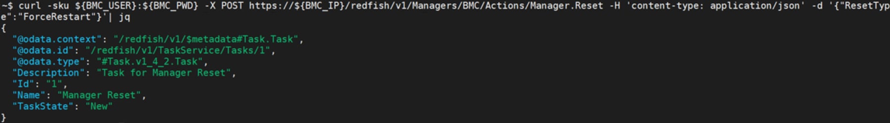
curl -sku {user}:{password} -X POST https://{BMC IP}/redfish/v1/Managers/BMC/Actions/Manager.Reset -H 'content-type: application/json' -d '{"ResetType":"ForceRestart"}'
This figure provides a reference example for executing BMC reset.
IPMI:
In-Band:
ipmitool mc reset
Out-of-Band:
ipmitool -I lanplus -H {BMC IP} -U {User} -P {Password} mc reset
This figure provides a reference example for executing BMC reset.
![]()
BMC to Factory Default
Redfish:
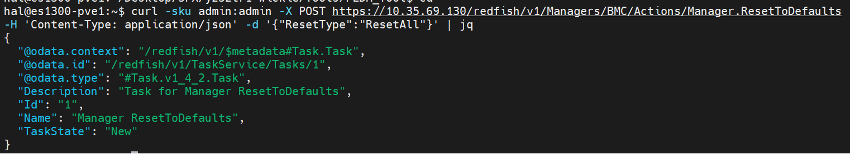
curl -sku {user}:{password} -X POST https://{BMC IP}/redfish/v1/Managers/BMC/Actions/Manager.ResetToDefaults" -H 'content-type: application/json' -d '{"ResetType":"ResetAll"}'
This figure provides a reference example for executing BMC to Factory Default.
 |
Preserve Configuration
To check if the configuration is preserved:
Redfish:
curl -sku {user}:{password} https://{BMC IP} /redfish/v1/Managers/BMC/Oem/Ami/PreserveConfigurations
This figure provides a reference example for getting preserve configuration.
To set the preserve configuration properties:
● Redfish:
curl -sku {user}:{password} -X PATCH -H 'content-type: application/json' -H 'If-Match:*' -d ' {"PreserveConfigurations": "{properties} ": {true or false}}' https://{BMC IP} /redfish/v1/Managers/BMC/Oem/Ami/PreserveConfigurations
This figure provides a reference example for editing preserve configuration.
Troubleshooting Operating System Issues
This section helps you troubleshoot operating system issues in your system.
NOTE: If the problem persists, contact Wistron Technical Support for further assistance.
How to Install the Operation System using Virtual Media - Ubuntu 24.04
Steps:
A. Prerequisites
1. Ensure that the server supports the operating system you intend to install.
2. Make sure you have the OS source media available for the server.
3. Prepare a storage location where you can store the necessary installation files.
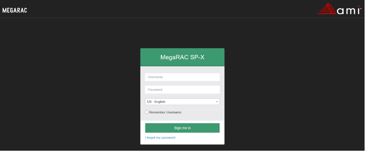
B. Access the BMC WebUI interface by entering the server's IP address in a web browser.
Note: The default username is admin and Password is admin.

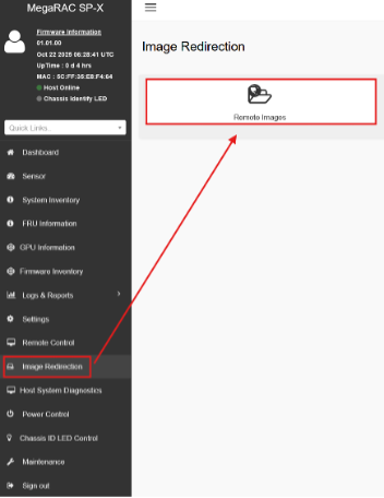
C. Go to Image Redirection to Mount OS Source media into the Virtual Media drive
1. Select Image Redirection -> Remote Images

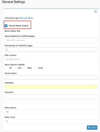
2. Click here to go to Media General Settings.
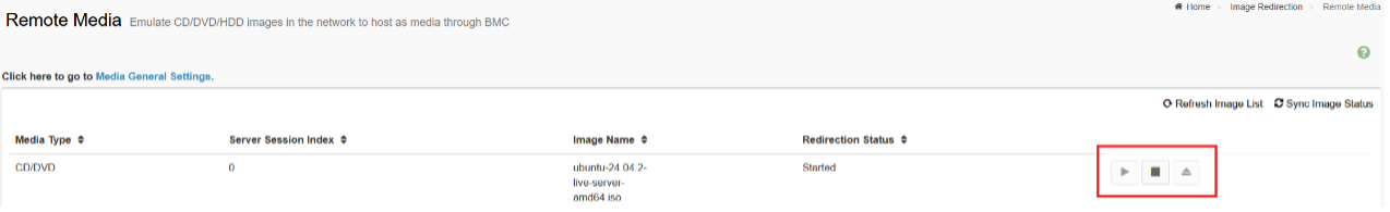
3. Click and Enable Remote Media Support.
3. Share Type for CD/DVD by nfs, cifs, https, smbe.
4. Set and Save.
4. After Setup the share type, go back to Remote Media, and then started the media.

5. Reboot the system and boot into BIOS to select virtual media CD/DVD and install operation system. Save the Changes, Reboot the Server, and Boot into the OS Installation Image.
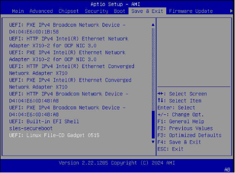
6. In the BIOS setup utility or boot menu, navigate to the "Save & Exit" section or a similar option.
7. Select the "UEFI: Linux File-CD Gadget 0515" or similar entry from the available boot devices.
8. Save the changes and exit the BIOS setup utility or boot menu.
9. The server will now boot from the selected boot device, which is the OS installation image on the virtual media drive.
 |
Once the installation completes, the server will reboot again, this time booting from the installed operating system on the server's local disk.
● GPU Mapping Table (Please refer to System Failure > Loss PCIE Device check).
Installing and installing Nvidia BLACKWELL HGX B300 NVL8 driver
Solution:
Ubuntu 24.04 (Noble Numbat) works well with these drivers via the official repositories or NVIDIA's CUDA toolkit. Below are step-by-step instructions using the recommended methods.
Prerequisites
Ensure your system has an NVIDIA B300 GPU installed and recognized: Run lspci | grep -i nvidia to confirm (look for something like "VGA compatible controller: NVIDIA Corporation Device [3182]" where 3182 is a Blackwell device ID).
1. Update your system:
sudo apt update && sudo apt upgrade -y
2. Install required build tools (for DKMS kernel modules):
sudo apt install build-essential linux-headers-$(uname -r) dkms
3. Disable Secure Boot in your BIOS/UEFI if enabled (Blackwell drivers often require it off for installation).
If using Nouveau (open-source driver), blacklist it:
sudo bash -c "echo 'blacklist nouveau' > /etc/modprobe.d/blacklist-nouveau.conf"
sudo bash -c "echo 'options nouveau modeset=0' >> /etc/modprobe.d/blacklist-nouveau.conf"
sudo update-initramfs -u
sudo reboot
● Method 1: Using Ubuntu's Built-in "Additional Drivers" Tool (Easiest for GUI Users)
This auto-detects your B300 and installs the recommended proprietary driver from Ubuntu's repos (typically 575+ on 24.04.2+).
1. Open "Software & Updates" from the Applications menu.
2. Go to the Additional Drivers tab.
3. Wait for it to scan your hardware—it should list options like nvidia-driver-575 or nvidia-driver-590 (select the highest version with "recommended").
4. Select the driver and click Apply Changes.
5. Enter your password and let it install (it may prompt a reboot).
6. Reboot: sudo reboot.
7. Verify: Run nvidia-smi—it should show your B300 GPU details.
If no Blackwell-compatible driver appears, proceed to Method 2.
● Method 2: Command-Line Installation via ubuntu-drivers (Recommended for Servers/CLI)
This tool automatically selects and installs the best driver for your B300.
1. Install the tool if needed:
sudo apt install ubuntu-drivers-common
2. List available drivers:
ubuntu-drivers devices
Look for your B300 and the recommended driver (e.g., nvidia-driver-590).
3. Install the recommended one:
sudo ubuntu-drivers autoinstall
Or specify: sudo ubuntu-drivers install nvidia:590 (replace 590 with the version from step 2).
4. Reboot: sudo reboot.
5. Verify: nvidia-smi.
For open kernel modules (often required for Blackwell stability): Use nvidia-driver-590-open instead.
● Method 3: Installing via NVIDIA's CUDA Repository (For AI/HPC Users)
1. Add the NVIDIA CUDA repo.
wget https://developer.download.nvidia.com/compute/cuda/repos/ubuntu2404/x86_64/cuda-keyring_1.1-1_all.deb
sudo dpkg -i cuda-keyring_1.1-1_all.deb
sudo apt update
2. Install the driver + CUDA.
sudo apt install cuda-drivers nvidia-driver-590 # Or latest version
For open modules: sudo apt install cuda-drivers-open nvidia-driver-590-open.
3. Reboot: sudo reboot.
4. Verify: nvidia-smi (shows GPU) and nvcc --version (for CUDA).
Troubleshooting
● "No devices found" in nvidia-smi: Ensure Nouveau is blacklisted and reboot. If persists, purge old drivers: sudo apt purge '^nvidia-*' && sudo apt autoremove, then reinstall.
● Kernel mismatch: Update to the latest kernel (6.8+): sudo apt install linux-generic-hwe-24.04.
● Blackwell-specific issues: Use open drivers (-open suffix) as some Blackwell firmware mandates them. Check NVIDIA forums for beta drivers if needed.
● Boot loop/black screen: Boot to recovery mode, purge drivers, and try an older version like 575.
● Test: Run prime-select query (for laptops) or glxinfo | grep NVIDIA for OpenGL.
For the absolute latest drivers, download the .run file from NVIDIA's site (e.g., version 590.xx for Blackwell) and install manually:
chmod +x NVIDIA-Linux-x86_64-590.xx.run
sudo ./NVIDIA-Linux-x86_64-590.xx.run –dkms
But stick to repo methods for easier updates.
If issues persist, provide output from lspci -v | grep VGA and dmesg | grep nvidia for more help.
How to isolate HW Failures on Nvidia BLACKWELL HGX B300 NVL8 products
Solution:
If you encounter the hardware failure of NVIDIA BLACKWELL HGX B300 NVL8, you can use partnerdiag diagnostics to isolate HW failures.
1. Installation
Please follow these steps:
1. Copy 629-PPPPP-KKKK-FLD-DDDDD.tgz to your system.
2. tar xfz 629-PPPPP-KKKK-FLD-DDDDD.tgz.
2. Running partnerdiag diagnostics
Please follow these steps:
1. cd 629-PPPPP-KKKK-FLD-DDDDD
2. Run partner ddiag
- Mfg : sudo ./partnerdiag --mfg --run_spec=spec_blackwell-hgx-b300-nvl8_partner_mfg.json --run_on_error --no_bmc
- Field: sudo ./partnerdiag --field --run_on_error --no_bmc
3. PASS/FAIL/RETEST will be displayed when partnerdiag finishes execution.
4. Run ./partnerdiag --help for more details on options.
If issues persist, provide logs to NVIDIA AE team for more help.
When an issue occurs (error or loss), please refer to the following sections for initial troubleshooting.
Symptom:
● The system has no response when the power button is pressed.
● The system power/health LED is abnormal.
Action:
● Check if there’s improperly seated component (e.g., PSU, CPU, DIMMs, cables..).
● Ensure the system FWs comply with the FW table. If not, please do firmware update.
● If the issue still exists, please contact R&D.
Symptom:
● The system hangs in POST.
● The system can’t complete POST.
Action:
● Check the 80 port and POST error messages, refer to POST code table to do the initial troubleshooting.
● Shut down the system and try to break the system down to the minimum hardware configuration first, then power on the system.
● Clear CMOS (power off the system and remove the CMOS battery, discharge for 30 seconds, and then reinstall it) and reboot the system.
● Ensure the system FWs comply with the FW table. If not, please do firmware update.
● If the issue still exists, please contact R&D.
Symptom:
● The system boots, but has no video output.
Action:
● Unplug mini-DP and plug again.
● If the issue still exists, please contact R&D.
Symptom:
● The system can’t boot an installed OS.
Action:
● Check if the OS is corrupted, replace it to another OS device.
● System only supports UEFI mode, check if user uses the legacy OS.
● Check if secure boot is enabled, if yes, please disable it in BIOS menu and reboot the system.
● If system can’t boot via OS path in Boot Override, try from the embedded EFI SHELL as below:
1. Find your OS partition and access it.
ex. Shell> fs1:
2. Access to the EFI folder.
ex. FS1> cd EFI
3. Access to the BOOT folder.
ex. FS1\EFI> cd BOOT
4. Execute the OS boot path
ex. FS1\EFI\BOOT> BOOTX64.EFI
Error occur after a BIOS setting is changed
Symptom:
● The system can’t boot normally after settings were changed.
Action:
● Clear CMOS to load default settings, and reboot system.
● Flash BIOS to restore the system to default settings.
● Check the system logs to determine the changes made, and change the settings back to the original configuration.
● If the issue still exists, please contact R&D.
Failure occurs during ROM flash via BMC web
Symptom:
● Any abnormal/error windows pop up during flash.
Action:
● Check if the BMC connection is normal.
● Check if the network cable is loose.
● Make sure to use the right ROM file.
● If there’s an interrupted during a ROM flash, or the ROM image is corrupted and the server does not start, re-flash the BIOS.
● If user still can't access BMC web to flash BIOS, please use copy machine to flash it (e.g., SF600)
● If the issue still exists, please contact R&D.
See the SERR or PERR error on SEL
Symptom:
● See the PERR/SERR error the same as example below:
![]()
Action:
● Find the EventData that we can decode to find which PCIe slot/device triggered the event.
● The way to decode:
So, 8220 indicates the PCIe device/slot 82/04/00.
● Please contact R&D and inform the PCIe slot/device that triggered the event.
PCI device not found / found but not plugged
Symptom:
● PCI device plugged but not found in PCI Subsystem Settings.
● PCI device found in PCI Subsystem Settings but not plugged in the system.
Action:
● Prepare the following information and contact R&D.
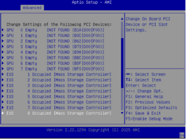
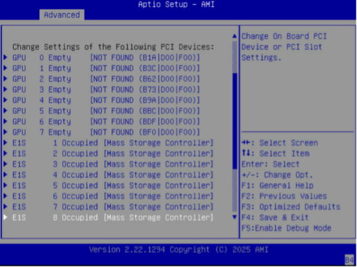
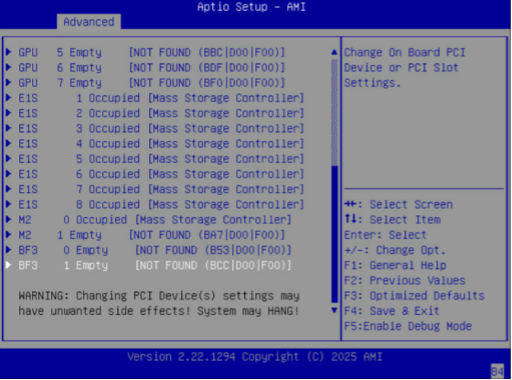
1. Take screenshots of PCI subpage.
● Enter PCI Subsystem Settings (Setup Page→Advanced menu)
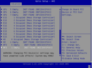
● Take screenshots of the subpage.

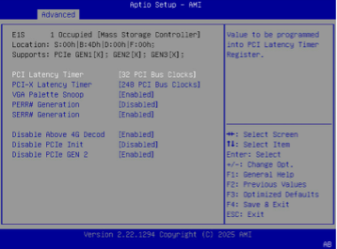
● Enter and take screenshots of the wrong-detected PCI device, example:
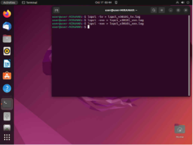
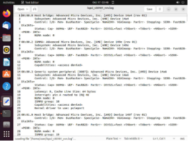
2. Dump PCIe Information from Linux OS:
● Make the following commands to dump lspci and save files
sudo lspci -tv > FILENAME_tv.log
sudo lspci -vvv > FILENAME_vvv.log
sudo lspci -xxx > FILENAME_xxx.log

● Example for tv.log
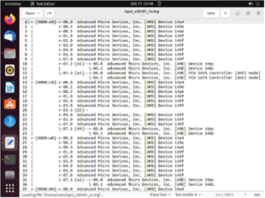 |
● Example for vvv.log
● Example for xxx.log
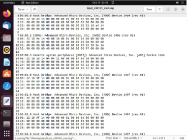 |
3. Dump PCIe Information from UEFI: Built-in EFI Shell.
● Switch to the USB. Make the following command to dump pci and save file
FS1:
pci > FILENAME_pci.log
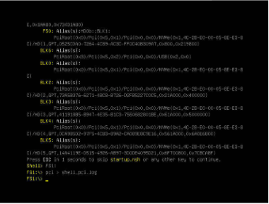
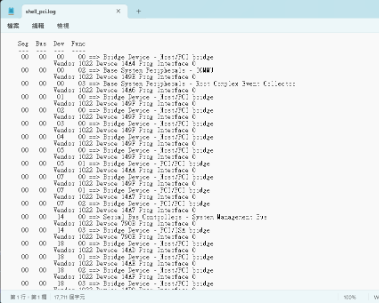
● Example for pci.log
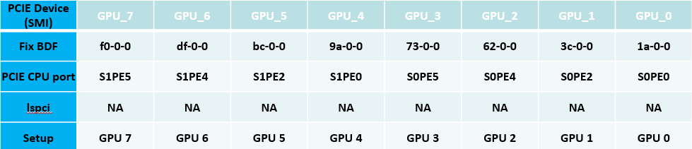
Fixed PFA for PCIe Slots
When an issue occurs (error or loss), please refer to the table below to find out the problematic devices.
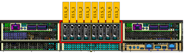
Table 7. E1.S PCIE Bus Mapping Capture
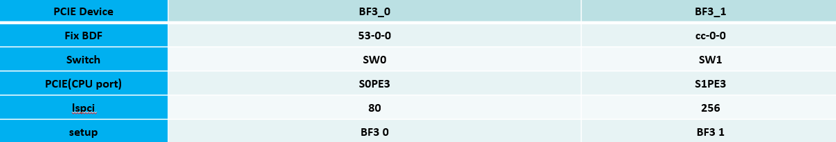
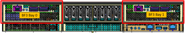
Table 8. BF3 PCIE Bus Mapping Capture
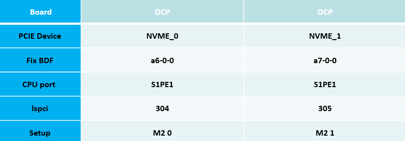
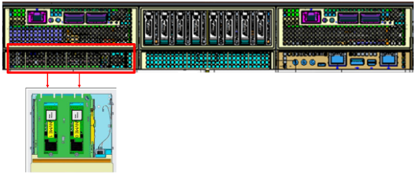
Table 9. OCP PCIE Bus Mapping Capture


Table 10. GPU Bus Mapping Capture
PCIE information in the Setup Page
The GPU server provides the status of all PCIe slots so that users can easily see if a PCIe device is plugged in or not.
AMI BIOS POST code
| 0x00 |
Not used |
| Progress Codes |
|
| 0x01 |
Power on. Reset type detection (soft/hard). |
| 0x02 |
AP initialization before microcode loading |
| 0x03 |
North Bridge initialization before microcode loading |
| 0x04 |
South Bridge initialization before microcode loading |
| 0x05 |
OEM initialization before microcode loading |
| 0x06 |
Microcode loading |
| 0x07 |
AP initialization after microcode loading |
| 0x08 |
North Bridge initialization after microcode loading |
| 0x09 |
South Bridge initialization after microcode loading |
| 0x0A |
OEM initialization after microcode loading |
| 0x0B |
Cache initialization |
| 0x0C - 0x0D |
Reserved for future AMI SEC error codes |
| 0x0E |
Microcode not found |
| 0x0F |
Microcode not loaded |
| Progress Codes |
|
| 0x10 |
PEI Core is started |
| 0x11 |
Pre-memory CPU initialization is started. |
| 0x15 |
Pre-memory NB Initialization |
| 0x19 |
Pre-memory SB Initialization. |
| 0x2B |
Memory Initialization - SPD Read |
| 0x2C |
Memory presence detection |
| 0x2D |
Gather Remaining SPD Data |
| 0x2E |
Train DDR |
| 0x2F |
Memory Initialization Start |
| 0x31 |
Memory Initialization Complete |
| 0x32 |
CPU POST-Memory Initialization |
| 0x33 |
CPU Cache initialization |
| 0x34 |
Application Processor(s) (AP) initialization |
| 0x35 |
BSP Selection |
| 0x36 |
SMM Initialization. |
| 0x37 |
POST-Memory NB Initialization |
| 0x3B |
POST-Memory SB Initialization |
| 0x4F |
DXE IPL is started |
| PEI Error Codes |
|
| 0x50 |
Memory initialization error. Invalid memory type or incompatible memory speed |
| 0x51 |
Memory initialization error. SPD reading has failed |
| 0x52 |
Memory initialization error. Invalid memory size or memory modules do not match. |
| 0x53 |
Memory initialization error. No usable memory detected |
| 0x54 |
Unspecified memory initialization error. |
| 0x55 |
Memory not installed |
| 0x56 |
Invalid CPU Type / Speed |
| 0x57 |
CPU Mismatch (SIMULATED) |
| 0x58 |
CPU self test failed or possible CPU cache error |
| 0x59 |
No MicroCode / MicroCode Update Failed |
| 0x5B |
reset PPI is not available |
| 0x5C - 0x5F |
Reserved for future AMI error codes |
DXE Phase
| Progress Codes |
|
| 0x60 |
DXE Core is started |
| 0x61 |
NVRAM initialization |
| 0x62 |
Install SB Runtime |
| 0x63 |
CPU DXE Initialization |
| 0x68 |
PCI HB Initialization |
| 0x69 |
NB DXE Initialization |
| 0x6A |
NB DXE SMM Initialization |
| 0x70 |
SB DXE Initialization |
| 0x71 |
SB DXE SMM Initialization. |
| 0x72 |
SB DEVICES Initialization |
| 0x78 |
ACPI Module Initialization |
| 0x79 |
CSM Driver Entry point |
| 0x7A – 0x7F |
Reserved for future AMI DXE codes |
| 0x80 – 0x8F |
OEM DXE initialization codes |
| 0x90 |
BDS Started. |
| 0x91 |
Driver connecting is started |
| 0x92 |
PCI Bus initialization is started |
| 0x93 |
PCI Bus Hot Plug Controller Initialization |
| 0x94 |
PCI Bus Enumeration |
| 0x95 |
PCI Bus Request Resources |
| 0x96 |
PCI Bus Assign Resources |
| 0x97 |
Console Output devices connect |
| 0x98 |
Console input devices connect |
| 0x99 |
Super IO Initialization |
| 0x9A |
USB initialization is started |
| 0x9B |
USB Reset |
| 0x9C |
USB Detect |
| 0x9D |
USB Enable |
| 0x9E – 0x9F |
Reserved for future AMI codes |
| 0xA0 |
IDE initialization is started |
| 0xA1 |
IDE Reset |
| 0xA2 |
IDE Detect |
| 0xA3 |
IDE Enable |
| 0xA4 |
SCSI Initialization |
| 0xA5 |
SCSI Reset |
| 0xA6 |
SCSI Detect |
| 0xA7 |
SCSI Enable |
| 0xA8 |
Setup Verifying Password |
| 0xA9 |
Start of Setup |
| 0xAA |
Reserved for ASL (see ASL Status Codes section below) |
| 0xAB |
Setup Key Press Wait |
| 0xAC |
Reserved for ASL (see ASL Status Codes section below) |
| 0xAD |
Ready To Boot event |
| 0xAE |
Legacy Boot event |
| 0xAF |
Exiting Boot Services |
| 0xB0 |
Virtual Address Begin |
| 0xB1 |
Virtual Address End |
| 0xB2 |
Legacy Option ROM Initialization |
| 0xB3 |
System Reset Initiated |
| 0xB4 |
USB hot plug |
| 0xB5 |
PCI Bus Hot Plug |
| 0xB6 |
Clean-up of NVRAM |
| 0xB7 |
Configuration Reset (reset of NVRAM settings) |
| 0xB8 – 0xBF |
Reserved for future AMI codes |
| 0xC0 – 0xCF |
OEM BDS initialization codes |
| DXE Error Codes |
|
| 0xD0 |
DXE CPU initialization error |
| 0xD1 |
DXE NB initialization error |
| 0xD2 |
South Bridge initialization error |
| 0xD3 |
Some Architectural Protocols are not available |
| 0xD4 |
PCI resource allocation error. Out of Resources |
| 0xD5 |
Not enough space for legacy OpROM |
| 0xD6 |
No Console Output Devices are found |
| 0xD7 |
No Console Input Devices are found |
| 0xD8 |
Invalid password |
| 0xD9 |
Error loading Boot Option (LoadImage returned error) |
| 0xDA |
Boot Option is failed (StartImage returned error) |
| 0xDB |
Flash update is failed |
| 0xDC |
Reset protocol is not available |
| S3 Resume Progress Codes |
|
| 0xE1 |
S3 Boot Script execution |
| 0xE3 |
OS S3 wake vector call |
| 0xE4-0xE7 |
Reserved for future AMI progress codes |
| S3 Resume Error Codes |
|
| 0xE8 |
S3 Resume Failed |
| 0xE9 |
S3 Resume PPI not Found |
| 0xEA |
S3 Resume Boot Script Error |
| 0xEB |
S3 OS Wake Error |
| 0xEC-0xEF |
Reserved for future AMI error codes |
| Recovery Progress Codes |
|
| 0xF0 |
Recovery condition triggered by firmware (Auto recovery) |
| 0xF1 |
Recovery condition triggered by user (Forced recovery) |
| 0xF2 |
Recovery process started |
| 0xF3 |
Recovery firmware image is found |
| 0xF4 |
Recovery Capsule Loaded |
| Recovery Error Codes |
|
| 0xF8 |
Recovery PPI is not available |
| 0xF9 |
Recovery capsule is not found |
| 0xFA |
Invalid recovery capsule |
| 0xFB-0xFF |
Reserved for future AMI error codes |
Appendix A: The way to output BIOS log
Physical UART
1. Plug the cable between HOST and SUT.
2. Open Tera Term/putty (Below use Tera Term to do the explanation).
3. Choose Serial and Enhanced COM Port.
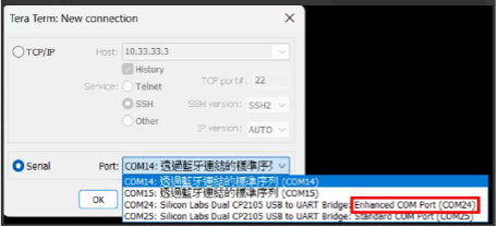
4. Select File > Log > Enter the file path you would like to keep the log and also the log name > Press Save.
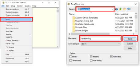 |
5. It will start to log the serial log once you finish step 5.
6. After above steps, please kindly send us the log for debugging.
To provide technical feedback on this document, or to report an error or omission, send your comments to apic-docfeedback@cisco.com. We appreciate your feedback.
Cisco and the Cisco logo are trademarks or registered trademarks of Cisco and/or its affiliates in the U.S. and other countries. To view a list of Cisco trademarks, go to this URL: http://www.cisco.com/go/trademarks. Third-party trademarks mentioned are the property of their respective owners. The use of the word partner does not imply a partnership relationship between Cisco and any other company. (1110R)
Any Internet Protocol (IP) addresses and phone numbers used in this document are not intended to be actual addresses and phone numbers. Any examples, command display output, network topology diagrams, and other figures included in the document are shown for illustrative purposes only. Any use of actual IP addresses or phone numbers in illustrative content is unintentional and coincidental.
© 2026 Cisco Systems, Inc. All rights reserved.
 Feedback
Contact Cisco
- Open a Support Case

- (Requires a Cisco Service Contract)