Status LEDs and Buttons
This section contains information for interpreting LED states.
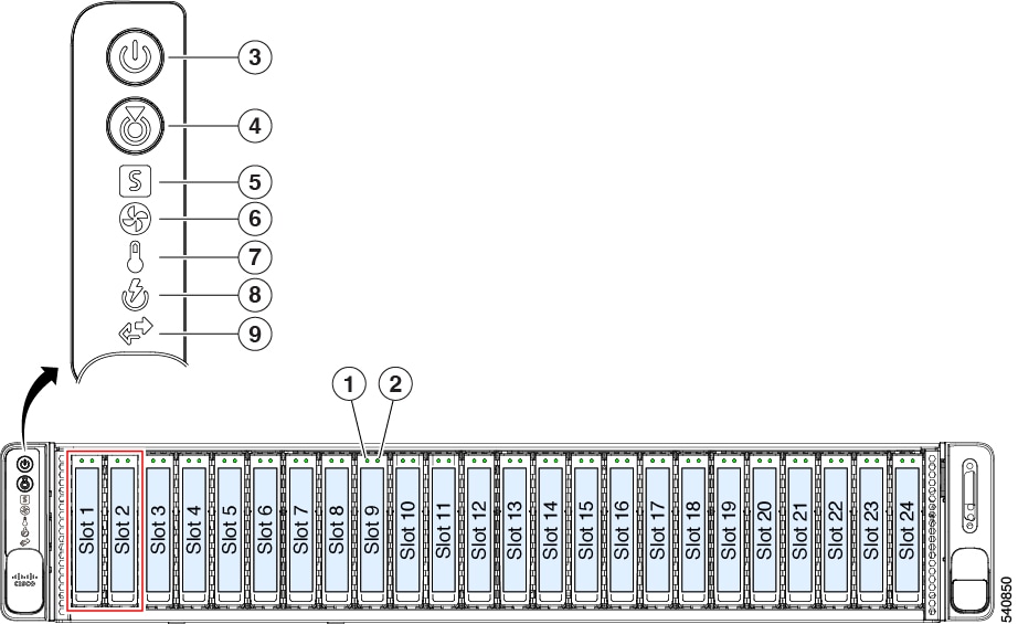
Front-Panel LEDs
|
LED Name |
States |
|||
|
1 SAS |
SAS/SATA drive fault
|
|
||
|
2 SAS |
SAS/SATA drive activity LED |
|
||
|
1 NVMe |
NVMe SSD drive fault
|
|
||
|
2 NVMe |
NVMe SSD activity |
|
||
|
3 |
Power button/LED |
|
||
|
4 |
Unit identification |
|
||
|
5 |
System health |
|
||
|
6 |
Fan status |
|
||
|
7 |
Temperature status |
|
||
|
8 |
Power supply status |
|
||
|
9 |
Network link activity |
|
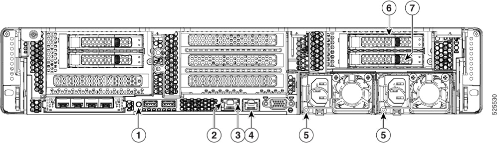
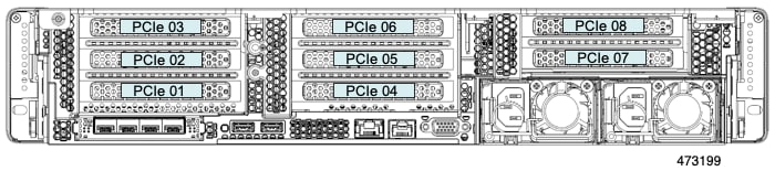
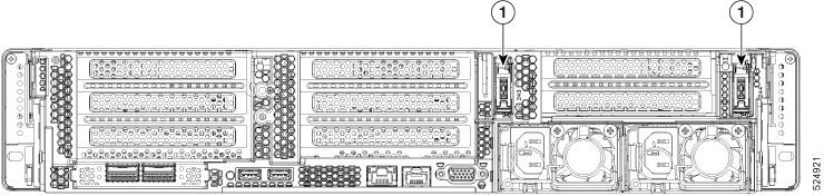
Rear-Panel LEDs
|
LED Name |
States |
|||
|
1 |
Unit identification LED |
|
||
|
2 |
1-Gb Ethernet dedicated management link speed |
|
||
|
3 |
1-Gb Ethernet dedicated management link status |
|
||
|
4 |
1-Gb Serial port |
|||
|
5 |
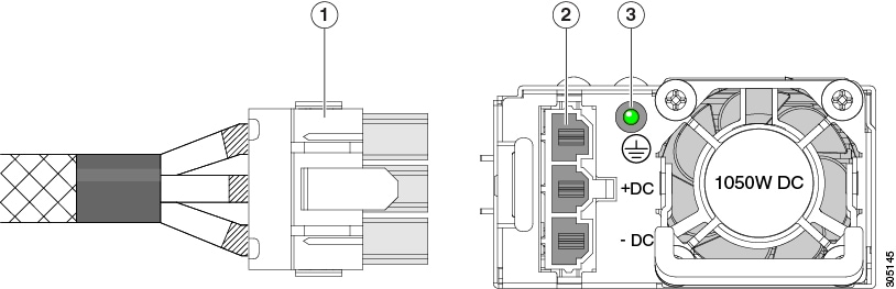
Power supply status (one LED each power supply unit) |
AC power supplies:
DC power supply (UCSC-PSUV2-1050DC):
|
||
|
6 SAS |
SAS/SATA drive fault
|
|
||
|
7 SAS |
SAS/SATA drive activity LED |
|
||
|
6 NVMe |
NVMe SSD drive fault
|
|
||
|
7 NVMe |
NVMe SSD activity |
|
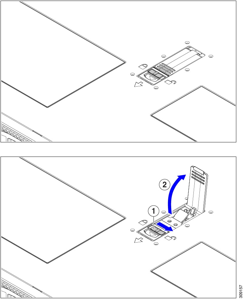
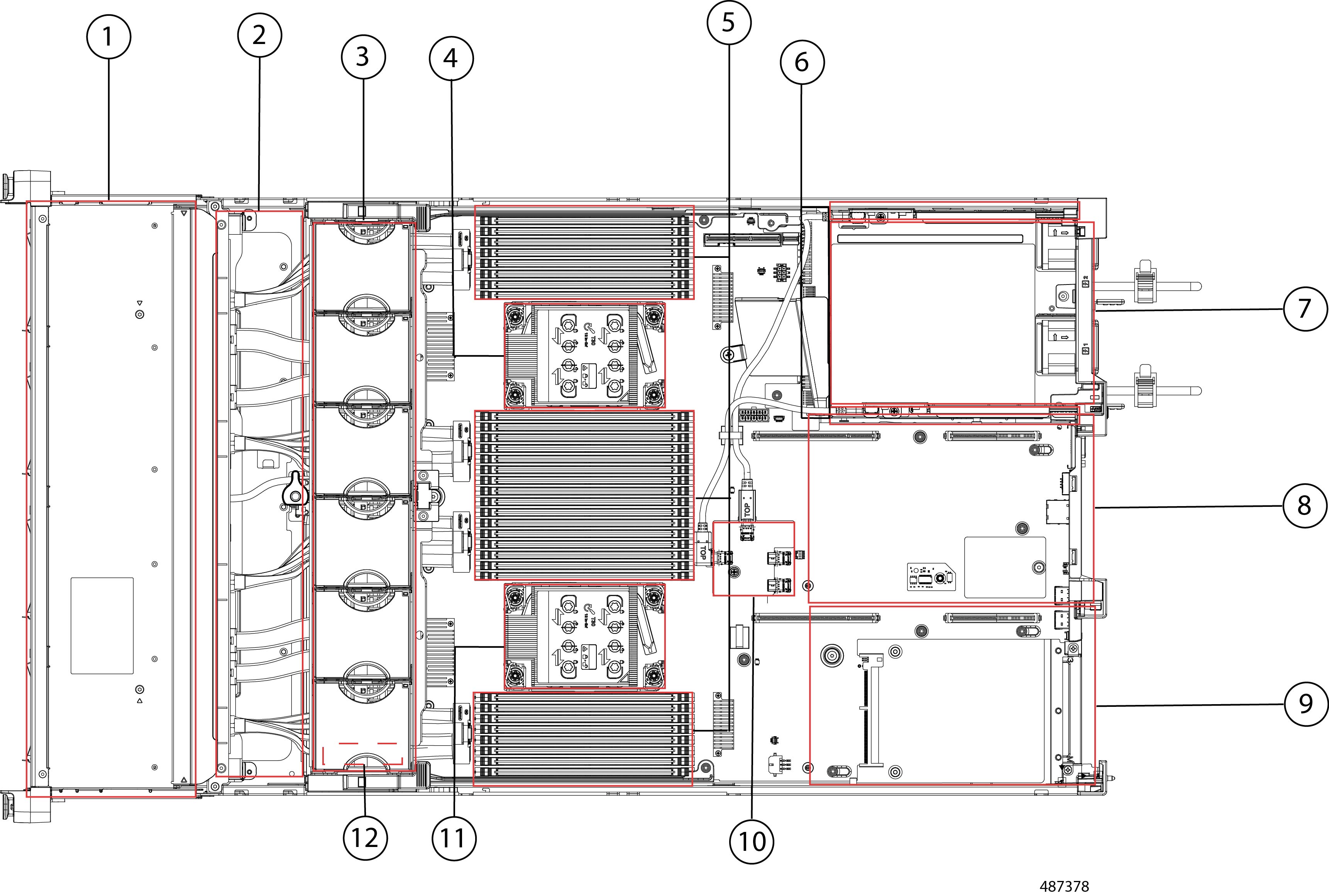
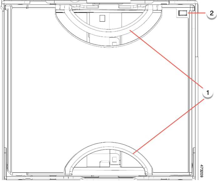
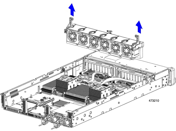
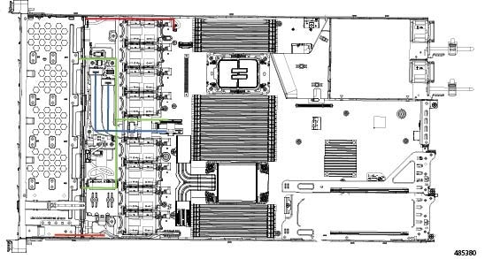
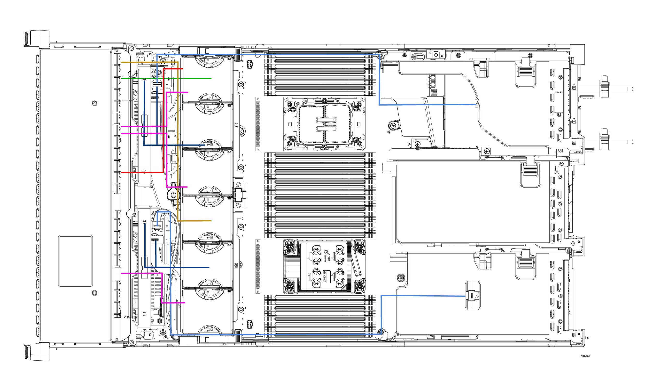
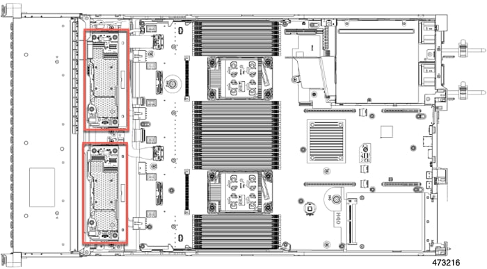
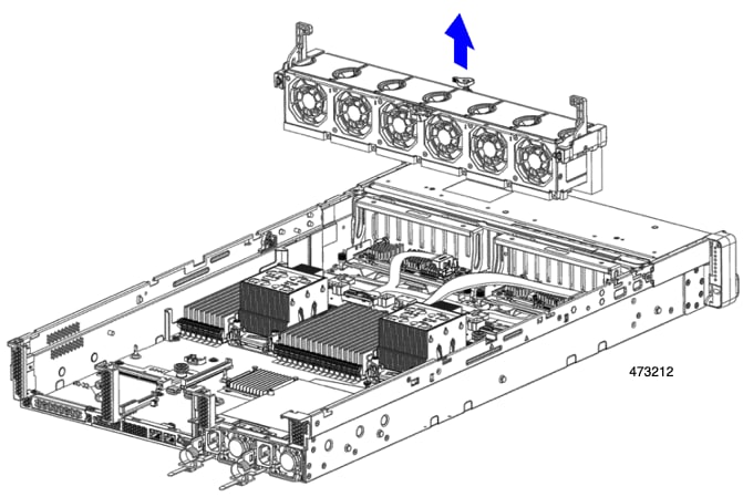
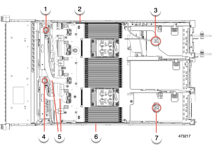
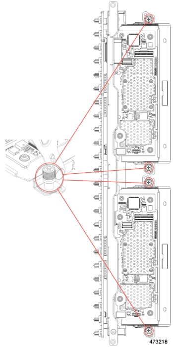
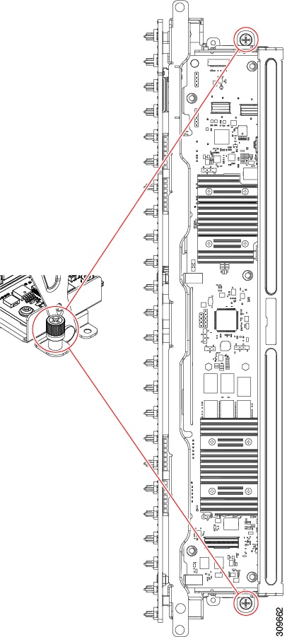
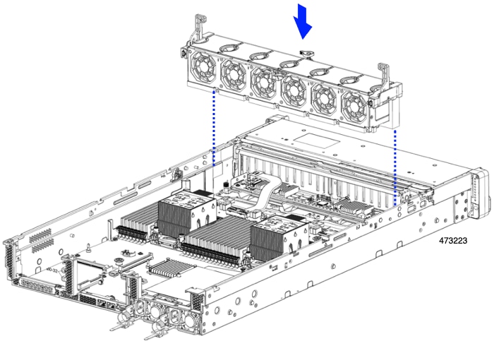
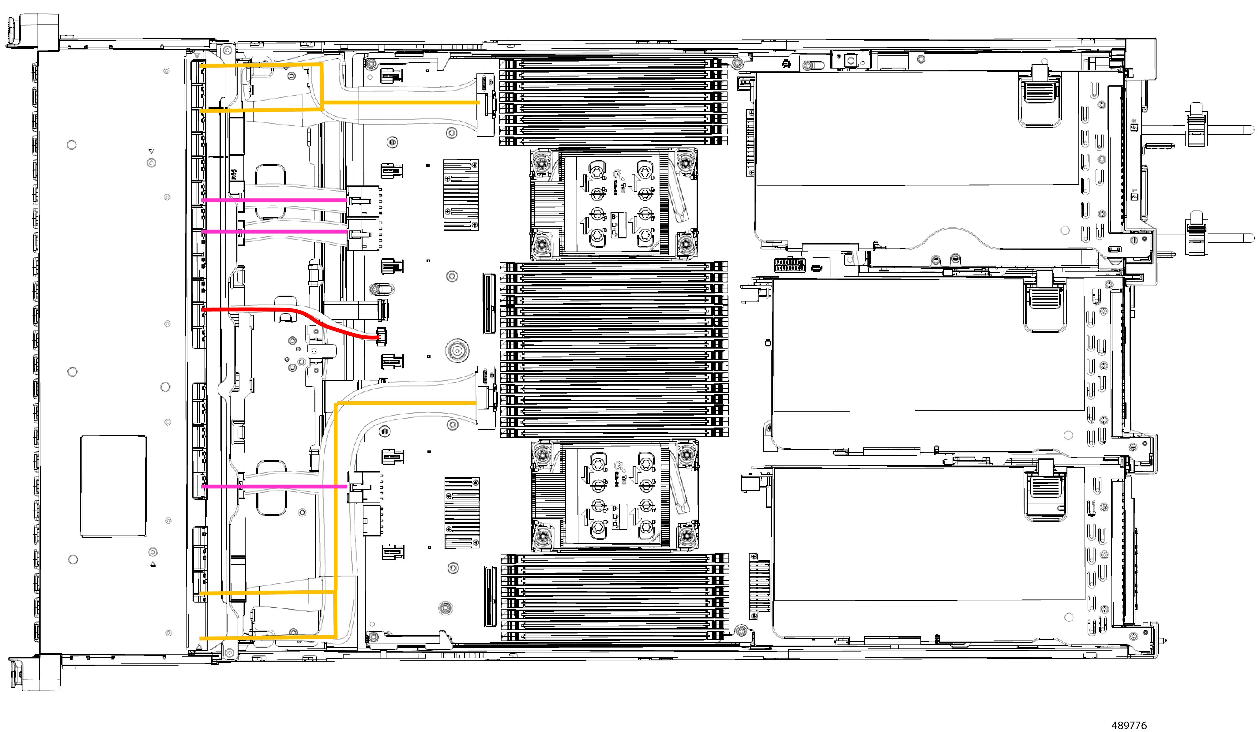
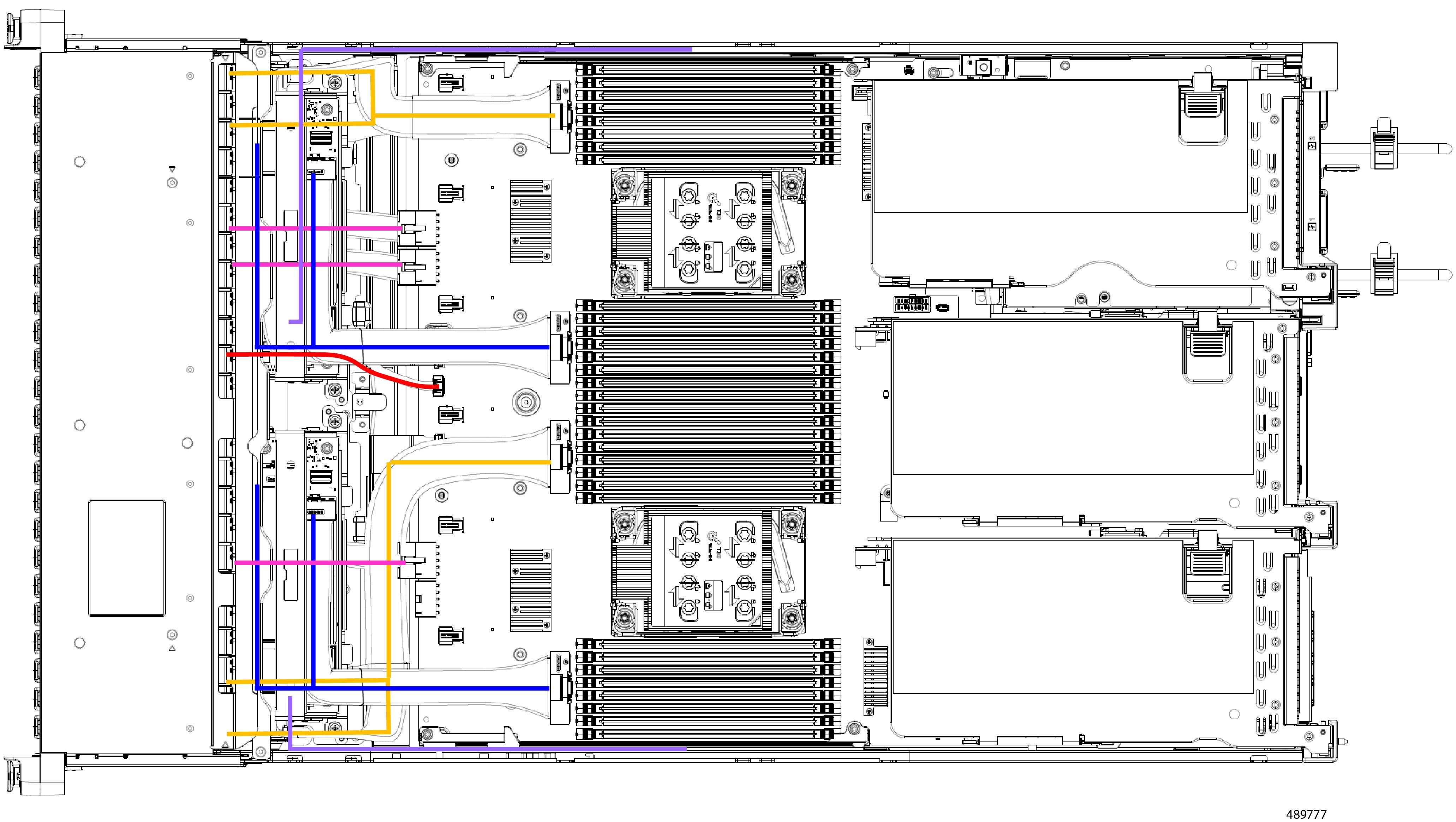
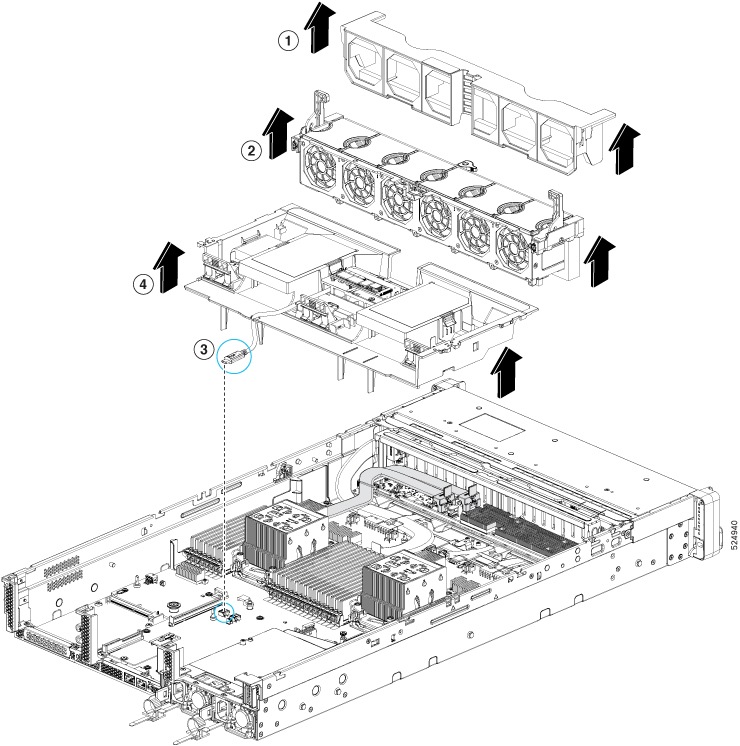
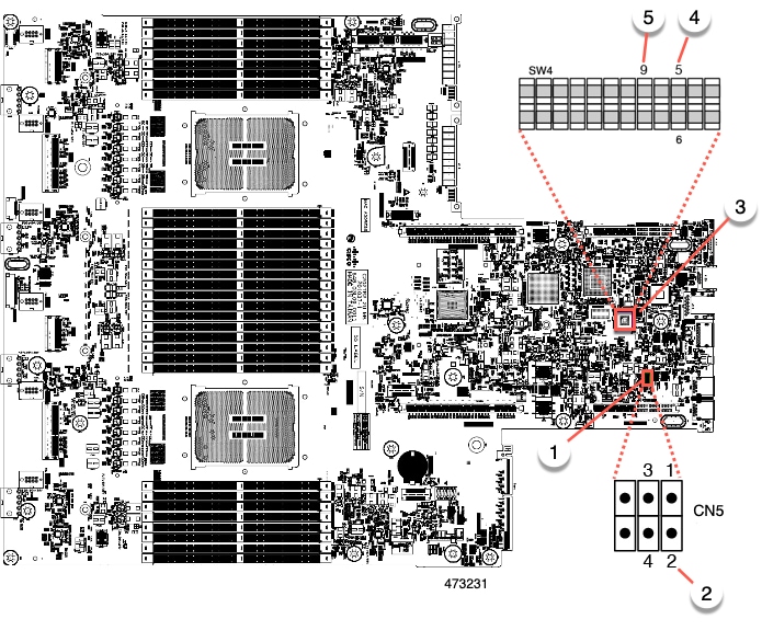
Internal Diagnostic LEDs
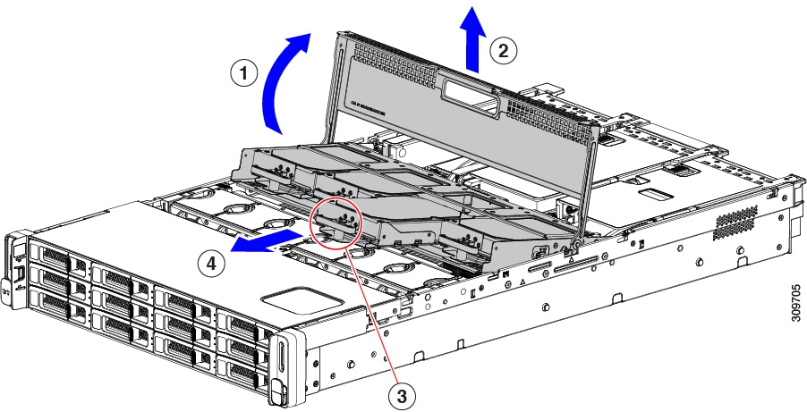
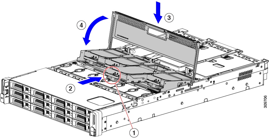
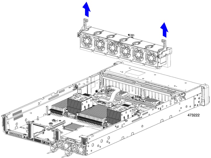
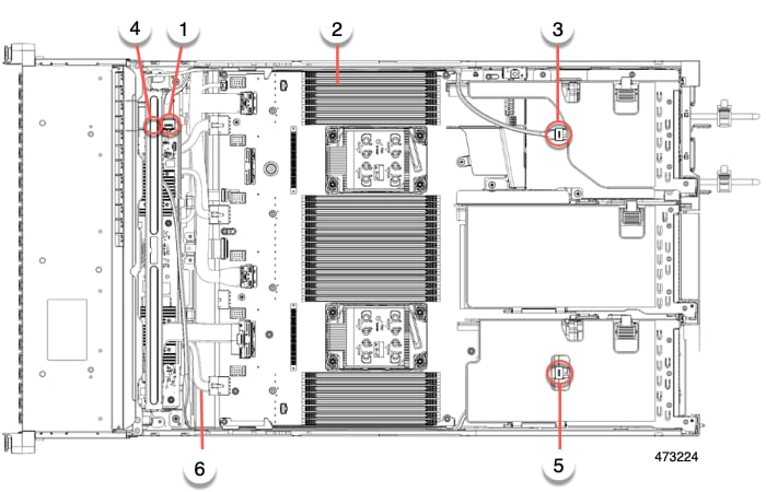
The server has internal fault LEDs for CPUs, DIMMs, and fan modules at the base of the CPUs, DIMMs, and fan modules.
|
1 |
Fan module fault LEDs (one on the top of each fan module)
|
3 |
DIMM fault LEDs (one behind each DIMM socket on the motherboard) These LEDs operate only when the server is in standby power mode.
|
|
2 |
CPU fault LEDs (one behind each CPU socket on the motherboard). These LEDs operate only when the server is in standby power mode.
|
- |


 Feedback