Overview
This chapter provides a summary overview of the Cisco UCS C480 ML M5 server.
The documentation set for this product strives to use bias-free language. For the purposes of this documentation set, bias-free is defined as language that does not imply discrimination based on age, disability, gender, racial identity, ethnic identity, sexual orientation, socioeconomic status, and intersectionality. Exceptions may be present in the documentation due to language that is hardcoded in the user interfaces of the product software, language used based on RFP documentation, or language that is used by a referenced third-party product. Learn more about how Cisco is using Inclusive Language.
This chapter provides a summary overview of the Cisco UCS C480 ML M5 server.
This topic shows the external features of the server.
For definitions of LED states, see Front-Panel LEDs.
|
1 |
Power button/LED |
8 |
Left bay module (drive bays 1 - 8)
|
|
2 |
Identification button/LED |
9 |
Center bay module (drive bays 9 - 16)
|
|
3 |
System status LED |
10 |
Right bay module, supports either:
|
|
4 |
Fan status LED |
11 |
KVM console connector (used with a KVM cable that provides two USB, one VGA, and one serial connector) |
|
5 |
Temperature status LED |
12 |
Pull-out asset tag |
|
6 |
Power supply status LED |
13 |
CPU module bay 1 The system must have one CPU module in lower bay 1 to boot. |
|
7 |
Network link activity LED |
14 |
CPU module bay 2 (blank with filler module) There must be a blank filler module in upper bay 2 or the system will not boot. |
For definitions of LED states, see Rear-Panel LEDs.
|
1 |
Serial port COM 1 (DB-9 connector) |
7 |
Rear identification button/LED |
|
2 |
VGA video port (DB-15 connector) |
8 |
USB 3.0 ports (three) |
|
3 |
Not used at this time |
9 |
Power supplies 1 – 4 (hot-swappable, redundant as 3+1) See Power Specifications for specifications and supported options. |
|
4 |
1-Gb/10-Gb Ethernet ports (LAN1 upper, LAN2 lower) The dual LAN ports can suport 1 Gbps and 10 Gbps, depending on the link-partner capability. |
10 |
PCIe slots 11 – 14 See PCIe Slot Specifications and Restrictions for slot specifications. |
|
5 |
10/100/1000 Ethernet dedicated management port (Base-T) |
- |
|
|
6 |
Not used at this time |
- |
This topic shows the locations of the field-replaceable components and service-related items.
The Technical Specifications Sheet for this server, which includes supported component part numbers, are at Cisco UCS Servers Technical Specifications Sheets (scroll down to Technical Specifications).
|
1 |
RAID controller card for front-loading SAS/SATA drives. (not visible in this view; position is near chassis floor under the CPU module) |
6 |
Power supplies 1 – 4 (hot-swappable, redundant as 3+1) |
||
|
2 |
Supercap (RAID backup) for front RAID controller (not visible in this view; mounting bracket position is on chassis wall under the CPU module) |
7 |
PCIe slots 11 and 12 (Gen-3 x16) Slots 11 and 12 support standby power. Slot 11 is the primary slot for a Cisco UCS VIC card, slot 12 is the secondary slot. |
||
|
3 |
Fan modules (four modules with two fans each; hot-swappable) |
8 |
Internal, vertical USB 2.0 socket on motherboard |
||
|
4 |
NVIDIA V100 SXM2 GPUs and heatsinks (eight)
|
9 |
Trusted platform module socket (TPM) on motherboard |
||
|
5 |
PCIe slots 13 and 14 (Gen-3 x16) See PCIe Slot Specifications and Restrictions for slot specifications. |
- |
|
10 |
CPU module bay 2 (blank with filler module) There must be a blank filler module in upper bay 2 or the system will not boot. |
14 |
Right bay module, supports either:
|
||
|
11 |
CPU module bay 1 The system must have one CPU module in lower bay 1 to boot. |
15 |
PCIe slots 11 through 14, rear panel openings |
||
|
12 |
Left bay module (drive bays 1 - 8)
|
16 |
I/O module
|
||
|
13 |
Center bay module (drive bays 9 - 16)
|
17 |
Power supplies 1 – 4 (hot-swappable, redundant as 3+1) All power supplies in the system must be identical (no mixing). |
|
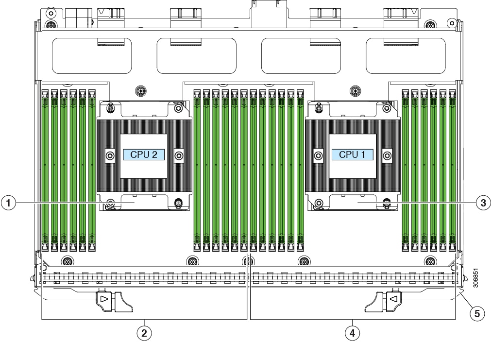
1 |
CPU 2 |
4 |
DIMM sockets controlled by CPU 1 (channels A, B, C, D, E, F.) |
|
2 |
DIMM sockets controlled by CPU 2 (channels G, H, J, K, L, M.) See DIMM Population Rules and Memory Performance Guidelines for DIMM slot numbering. |
5 |
Release levers for module (two each module) |
|
3 |
CPU 1 |
- |

|
1 |
Micro SD card socket |
3 |
RTC battery vertical socket |
|
2 |
Mini storage module connector Supports either an SD card carrier with two SD card slots or an M.2 SSD carrier with two SATA M.2 SSD slots. |
- |
The following table lists a summary of server features.
|
Feature |
Description |
|---|---|
|
Chassis |
Four rack-unit (4RU) chassis |
|
Central Processor |
The server supports one removable CPU module with two CPUs from the Intel Xeon Processor Scalable Family. This includes CPUs from the following series:
|
|
Memory |
Each of the CPUs support up to 12 DIMMs for a total of 24 DIMMs. |
|
Multi-bit error protection |
Multi-bit error protection is supported |
|
Baseboard management |
BMC, running Cisco Integrated Management Controller (Cisco IMC) firmware. Depending on your Cisco IMC settings, Cisco IMC can be accessed through the 1-Gb dedicated management port, the 1-Gb/10-Gb Ethernet LAN ports, or a Cisco virtual interface card. |
|
Network and management I/O |
The network and management I/O ports for this server are on a removeable I/O module:
Front panel:
|
|
Power |
Four power supplies, redundant as 3+1:
Do not mix power supply types or wattages in the server. |
|
ACPI |
The advanced configuration and power interface (ACPI) 4.0 standard is supported. |
|
Cooling |
Four hot-swappable fan modules with two fans in each for front-to-rear cooling. |
|
PCIe I/O |
Four vertical PCIe expansion slots on the chassis motherboard. See PCIe Slot Specifications and Restrictions for specifications of the slots. |
|
InfiniBand |
The PCIe bus slots in this server support the InfiniBand architecture. |
|
Storage, front-panel |
The server can hold up to 24 front-loading, 2.5-inch drives. Front drive bays are divided across 3 removable drive bay modules. Each drive bay module has 8 drive bays for a total of 24 front-loading drive bays.
|
|
Storage, internal |
The server has these internal storage options:
|
|
Other removable media |
A DVD drive module option is available in place of the right drive bay module. |
|
Storage management |
Front-loading storage: the server has a dedicated internal socket near the chassis front for a single storage controller card (RAID). This controller card can control up to 24 front-loading drives. For a detailed list of storage controller options, see Supported Storage Controllers and Cables. |
|
RAID supercap backup |
There is a bracket on the chassis wall for a supercap unit that backs up a front RAID controller for front-loading drives. |
|
Integrated video |
Integrated VGA video. |
 Feedback