Replacing Node Components

This chapter contains procedures for replacing components that are internal to the node.


Note


For replacement of components that are native to the C4200 Server Chassis (storage drives, supercap units, and power supplies), see the C4200 HIG.


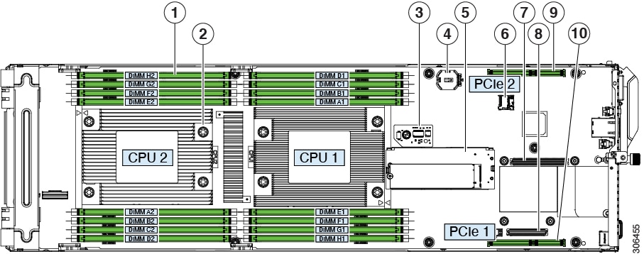
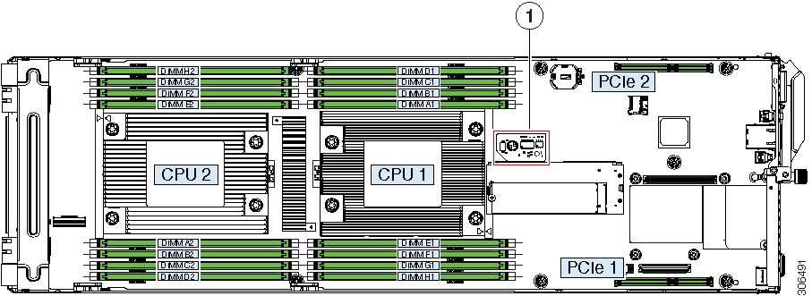
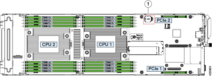
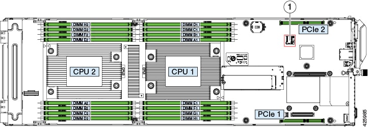
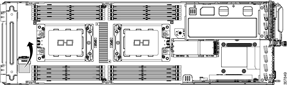
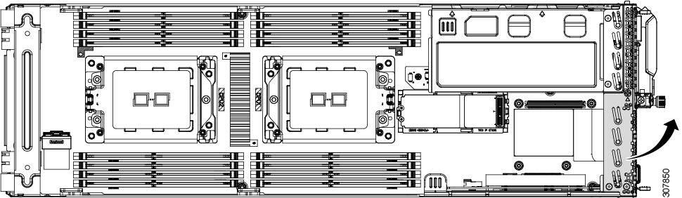
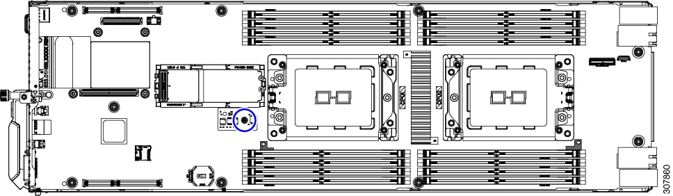
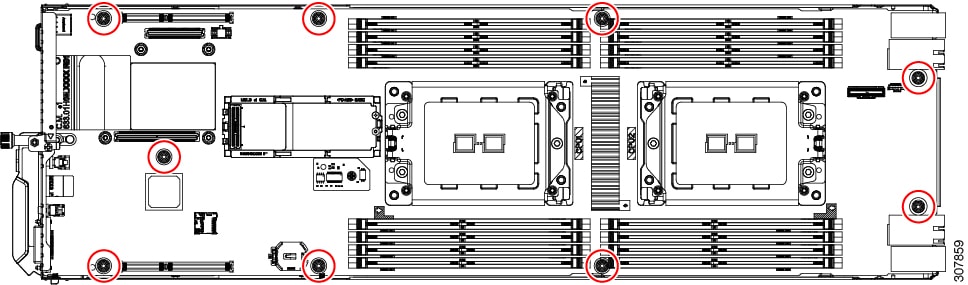
C125 M5 Compute Node Internal Component Locations

Figure 1. C125 M5 Compute Node Internal Components

1

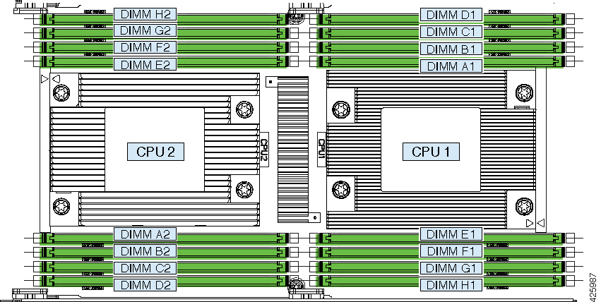
DIMM sockets (each CPU supports 8 sockets, 16 total)

6

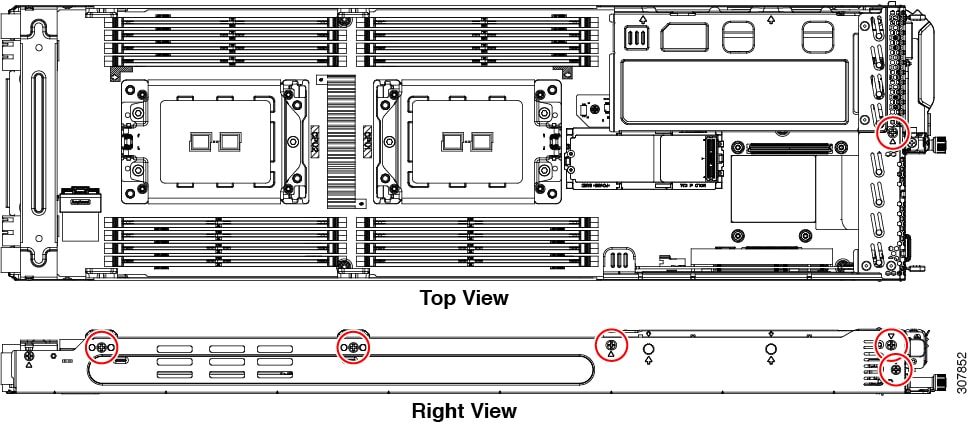
Micro-SD card socket on server board

2

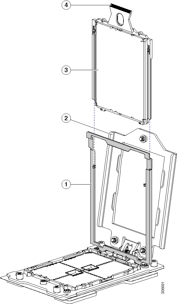
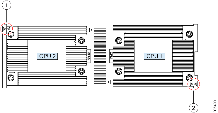
AMD EPYC 7001 Series (Naples) and Second Generation AMD EPYC 7002 Series (Rome) CPUs and heatsinks (one or two)

The front and rear CPUs use different heatsinks.

7

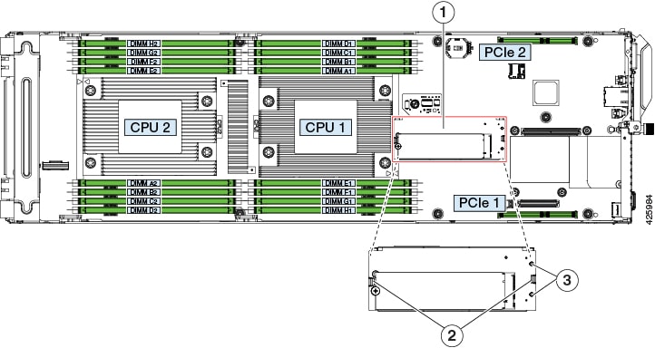
OCP adapter card socket A

OCP adapter cards that require a x8 lane plug into only socket A. OCP cards that require a x16 lane plug into both sockets A and B.

3

Trusted platform module (TPM) location on server board

8

OCP adapter card socket B

OCP adapter cards that require a x8 lane plug into only socket A. OCP cards that require a x16 lane plug into both sockets A and B.

4

Real-time clock (RTC) battery CR2032 horizontal socket location on server board

9

Socket for PCIe riser 2/ PCIe slot 2 (riser not shown in this view)

Riser 2 plugs into a board socket to provide one horizontal PCIe slot (half-height, half length, x16 slot).
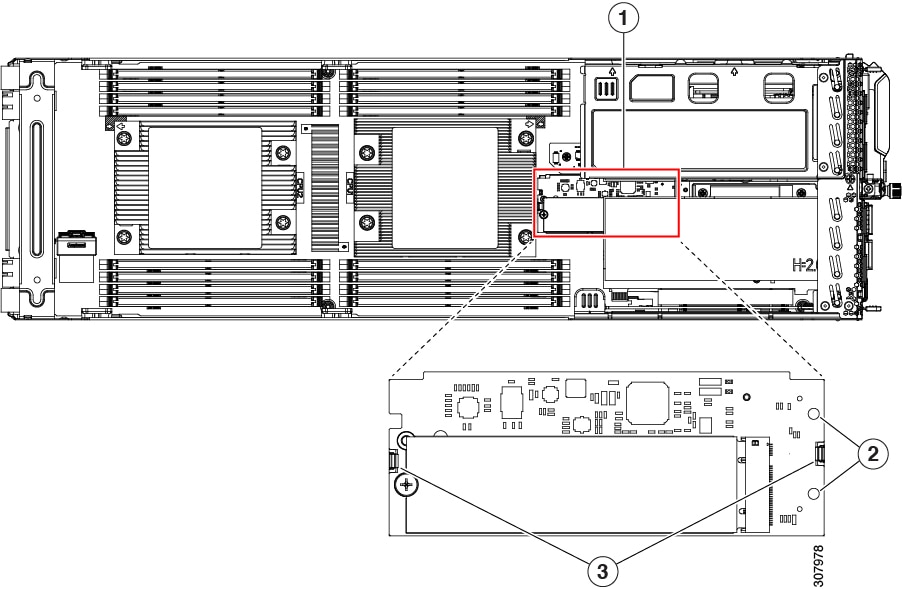
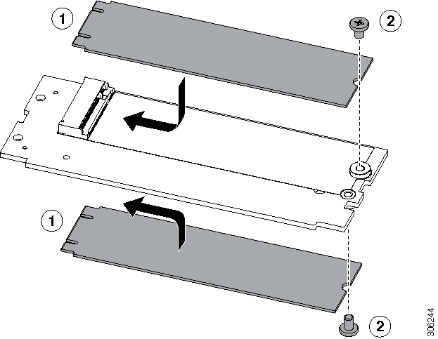
5

Mini-storage module socket on server board. Supports:

  • an SD card carrier with two slots for SD cards

  • an M.2 SSD carrier with two slots for M.2 SATA SSDs

  • a Cisco Boot-Optimized M.2 RAID Controller

10

Socket for PCIe riser 1/PCIe slot 1 (riser not shown in the is view)

Riser 1 plugs into this socket to provide one horizontal PCIe slot (half-height, half length, x8 slot).

This is the required slot for a SAS RAID controller. The controller supports the six front-loading drives in the chassis that correspond to the node's position (group 1, 2, 3, or 4).

Riser 1 also includes one x8 Slimline connector for pass-through (JBOD) SATA drive control.

Required Equipment For Service Procedures

The following tools and equipment are used to perform the procedures in this chapter:

  • T-20 Torx driver (for CPU and heatsink replacement)

  • #1 Phillips-head screwdriver for M.2 SSD replacement.

  • #2 Phillips-head screwdriver for PCIe riser/PCIe card replacement.

  • ΒΌ-inch (or equivalent) flat-head screwdriver (for TPM installation)

  • Electrostatic discharge (ESD) strap or other grounding equipment such as a grounded mat

Replacing Memory DIMMs

There are 16 DIMM sockets on the node board, 8 DIMMs controlled by each CPU.


Caution


DIMMs and their sockets are fragile and must be handled with care to avoid damage during installation.


Caution


Cisco does not support third-party DIMMs. Using non-Cisco DIMMs in the system might result in system problems or damage to the motherboard.


Note


To ensure the best system performance, it is important that you are familiar with memory performance guidelines and population rules before you install or replace the memory.


DIMM Sockets

A node has 16 DIMM sockets (8 for each CPU). The following figure shows the DIMM sockets and how they are numbered on a C125 M5 compute node board.

The DIMM channels consist of two lettered slots (for example, A1, A2). Note however that the two slots in a channel are placed on opposite sides of the two CPUs.

Figure 2. DIMM and CPU Numbering

DIMM Population Rules

AMD CPUs do not require a specific loading order for memory DIMMs. However, observe the following recommended guidelines for best performance:

  • Any unused DIMM socket must have a DIMM blanking panel installed to ensure adequate airflow and cooling.

  • For best performance, each CPU should have at least four DIMMs installed.

  • You must populate the DIMM slots of each CPU identically. Therefore, a two-CPU node must always have an even number of DIMMs. For optimal performance, populate DIMMs in the order shown in the following table, depending on the number of DIMMs per CPU.

    • In a single-CPU node, populate only the CPU 1 slots.

    • In a two-CPU node, populate slots for both CPUs evenly, as described in the table below.

    Table 1. DIMM Population Order

    Number of DIMMs Per CPU

    CPU 1 Slots

    (In a single-CPU node, populate only these slots)

    CPU 2 Slots

    1

    A1

    A2

    2

    A1, E1

    A2, E2

    3

    A1, E1, C1

    A2, E2, C2

    4

    A1, E1, C1, G1

    A2, E2, C2, G2

    5

    A1, E1, C1, G1, B1

    A2, E2, C2, G2, B2

    6

    A1, E1, C1, G1, B1, F1

    A2, E2, C2, G2, B2, F2

    7

    A1, E1, C1, G1, B1, F1, D1

    A2, E2, C2, G2, B2, F2, D2

    8

    A1, E1, C1, G1, B1, F1, D1, H1

    A2, E2, C2, G2, B2, F2, D2, H2

  • Observe the DIMM mixing rules in the following table.

Table 2. DIMM Mixing Rules

DIMM Parameter

Rules

DIMM capacity

You can mix different capacity DIMMs.

DIMM speed

You can mix speeds, but DIMMs will run at the speed of the slowest DIMMs/CPUs.

DIMM type

You cannot mix DIMM types.

Replacing DIMMs


Caution


Always shut down the node before removing it from the chassis, as described in the procedures. Failure to shut down the node before removal results in the corresponding RAID supercap cache being discarded and other data might be lost.


Procedure


Step 1

Shut down the server node by using the software interface or by pressing the node power button, as described in Shutting Down and Removing Power From a Node.

Step 2

Disconnect any cables from ports on the node or installed cards.

Step 3

Remove the node from the system:

  1. Loosen the captive thumbscrew on the ejector lever of the node.

  2. Rotate the ejector lever to the outside to evenly disengage the node from its midplane connectors.

  3. Pull the node straight out from the system.

Step 4

Locate the faulty DIMM and remove it from the socket on the riser by opening the ejector levers at both ends of the DIMM socket.

Step 5

Install a new DIMM:

Note


Before installing DIMMs, refer to the population guidelines. See DIMM Population Rules.

  1. Align the new DIMM with the socket on the riser. Use the alignment key in the DIMM socket to correctly orient the DIMM.

  2. Push the DIMM into the socket until it is fully seated and the ejector levers on either side of the socket lock into place.

Step 6

Return the server node to the chassis:

  1. With the ejector lever fully open, align the new node with the empty bay.

  2. Push the server node into the bay until it engages with the midplane connectors and is flush with the chassis.

  3. Rotate the ejector lever toward the center until it lays flat.

  4. Tighten the thumbscrew on the ejector lever to secure the node in the chassis bay.

Step 7

Reconnect any cables that you removed.

Step 8

Power on the server node.


Replacing CPUs and Heatsinks

Each node contains one or two AMD CPUs.

CPU Configuration Rules

  • A node can operate with one or two CPUs.

  • In a single-CPU configuration, populate only CPU1.

  • The maximum supported wattage for the node's CPUs is 200W, which are capped to run at 180W.

  • In a single-CPU configuration, only the DIMM slots for CPU 1 (DIMM A1 – H1) are supported.

Tools Required For CPU Replacement

You need the following tools and equipment for this procedure:

  • T-20 Torx driver (for heatsink and CPU socket screws).

  • Heatsink cleaning kitβ€”Supplied with replacement CPU. Orderable separately as Cisco PID UCSX-HSCK=.

    One cleaning kit can clean up to four CPUs.

  • Thermal interface material (TIM)β€”Syringe supplied with replacement CPU. Use only if you are reusing your existing heatsink (new heatsinks have a pre-applied pad of TIM). Orderable separately as Cisco PID UCS-CPU-TIM=.

    One TIM kit covers one CPU.

See also Additional CPU-Related Parts to Order with RMA Replacement CPUs or RMA Nodes.

Replacing a CPU and Heatsink


Caution


CPUs and their sockets are fragile and must be handled with extreme care to avoid damaging pins. The CPUs must be installed with heatsinks and thermal interface material to ensure cooling. Failure to install a CPU correctly might result in damage to the server node.


Caution


Always shut down the node before removing it from the chassis, as described in the procedures. Failure to shut down the node before removal results in the corresponding RAID supercap cache being discarded and other data might be lost.


Procedure


Step 1

Shut down the node by using the software interface or by pressing the node power button, as described in Shutting Down and Removing Power From a Node.

Step 2

Disconnect any cables from ports on the node or installed cards.

Step 3

Remove the node from the system:

  1. Loosen the captive thumbscrew on the ejector lever of the node.

  2. Rotate the ejector lever to the outside to evenly disengage the node from its midplane connectors.

  3. Pull the node straight out from the system.

Step 4

Remove the heatsink from the CPU that you are replacing:

  1. Use a T-20 Torx driver to loosen the four captive screws that secure the heatsink.

    Note


    Alternate loosening the heatsink screws evenly so that the heatsink remains level as it is raised. Loosen the heatsink nuts in the order shown on the heatsink label (4, 3, 2, 1).

  2. Lift straight up on the heatsink and set it heatsink-down on an antistatic surface. Use caution to avoid damaging the heatsink-to-CPU surface.

    Figure 3. Removing the Heatsink

Step 5

Remove the CPU from the socket:

  1. Use the T-20 Torx driver to loosen the three captive socket-frame screws in this order: 3, 2, 1.

    Figure 4. Loosening the Socket Frame Screws
  2. Pivot the hinged socket frame and rail frame to the upright position.

  3. Grasp the CPU only by the handling tab that is on its carrier frame and pull straight up to remove the CPU from the rail frame.

Figure 5. Removing the CPU From the Socket

1

Rail frame in open position

3

CPU in carrier frame

2

Socket frame in open position

4

Handling tab on CPU carrier frame

Step 6

Install the new CPU:

Caution


The CPU contacts and pins are extremely fragile. In this step, use extreme care to avoid touching or damaging the CPU contacts or the CPU socket pins.

Note


Ensure that you are following the CPU Configuration Rules.

  1. Grasping the CPU only by the handling tab on its carrier frame, carefully slide it down into the open rail frame.

  2. Gently close the rail frame and the socket frame down to the flat, closed position.

  3. Tighten the three screws on the socket frame in this order: 1, 2, 3.

Step 7

Apply new TIM to the heatsink:

Note

 
The heatsink must have new TIM on the heatsink-to-CPU surface to ensure proper cooling and performance.
  • If you are installing a new heatsink, it is shipped with a pre-applied pad of TIM. Go to step 7.

  • If you are reusing a heatsink, you must remove the old TIM from the heatsink and then apply new TIM to the CPU surface from the supplied syringe. Continue with step a below.

  1. Apply the cleaning solution that is included with the heatsink cleaning kit (UCSX-HSCK=) to the old TIM on the heatsink and let it soak for a least 15 seconds.

  2. Wipe all of the TIM off the heatsink using the soft cloth that is included with the heatsink cleaning kit. Be careful to avoid scratching the heatsink surface.

  3. Using the syringe of TIM provided with the new CPU (UCS-CPU-TIM=), apply 1.5 cubic centimeters (1.5ml) of thermal interface material to the top of the CPU. Use the pattern shown below to ensure even coverage.

    Figure 6. Thermal Interface Material Application Pattern

Step 8

Install the heatsink to the CPU:

Note


The front and rear CPUs use different heatsinks. The rear CPU (CPU1) uses heatsink UCSC-HS2-C125. The front CPU (CPU2) uses heatsink UCSC-HS-C125.

  1. Align the heatsink over the CPU socket. Align the triangle-mark on the heatsink with the triangle-mark on the socket frame, as shown in the following figure.

    Figure 7. Heatsink Alignment Marks

    1

    Triangle marks on front heatsink UCSC-HS-C125 and CPU 2 socket.

    2

    Triangle marks on rear heatsink UCSC-HS2-C125 and CPU 1 socket.

  2. Use a T-20 Torx driver to tighten the four captive screws that secure the heatsink.

    Caution

     
    Alternate tightening the heatsink screws evenly so that the heatsink remains level while it is lowered. Tighten the heatsink screws in the order shown on the heatsink label (1, 2, 3, 4).

Step 9

Return the node to the chassis:

  1. With the ejector lever fully open, align the new node with the empty bay.

  2. Push the server node into the bay until it engages with the midplane connectors and is flush with the chassis.

  3. Rotate the ejector lever toward the center until it lays flat.

  4. Tighten the thumbscrew on the ejector lever to secure the node in the chassis bay.

Step 10

Reconnect any cables that you removed.

Step 11

Power on the server node.


Additional CPU-Related Parts to Order with RMA Replacement CPUs or RMA Nodes

When a return material authorization (RMA) of the CPU is done on a node, additional parts might not be included with the CPU spare. The TAC engineer might need to add the additional parts to the RMA to help ensure a successful replacement.

  • Scenario 1β€”You are reusing the existing heatsinks or moving CPUs and heatsinks to a new node:

    • Heatsink cleaning kit (UCSX-HSCK=)

      One cleaning kit can clean up to four CPUs.

    • Thermal interface material (TIM) kit (UCS-CPU-TIM=)

      One TIM kit covers one CPU.

  • Scenario 2β€”You are replacing the existing heatsinks:


    Caution


    Use only the correct heatsink for your CPUs to ensure proper cooling. The front and rear CPUs use different heatsinks. The rear CPU (CPU1) uses UCSC-HS2-C125. The front CPU (CPU2) uses heatsink UCSC-HS-C125.
    • Heatsink: UCSC-HS-C125= or UCSC-HS2-C125=

      New heatsinks have a pre-applied pad of TIM.

    • Heatsink cleaning kit (UCSX-HSCK=)

      One cleaning kit can clean up to four CPUs.

A CPU heatsink cleaning kit is good for up to four CPU and heatsink cleanings. The cleaning kit contains two bottles of solution, one to clean the CPU and heatsink of old TIM and the other to prepare the surface of the heatsink.

New heatsink spares come with a pre-applied pad of TIM. It is important to clean any old TIM off of the CPU surface prior to installing the heatsinks. Therefore, even when you are ordering new heatsinks, you must order the heatsink cleaning kit.

Installing and Enabling a TPM

The trusted platform module (TPM) is a small circuit board that plugs into a node board socket and is then permanently secured with a one-way screw.


Note


Field replacement of a TPM is not supported; you can install a TPM after-factory only if the server does not already have a TPM installed.

This topic contains the following procedures, which must be followed in this order when installing and enabling a TPM:

  1. Installing the TPM Hardware

  2. Enabling the TPM in the BIOS

TPM Considerations

  • This server supports TPM version 2.0. The TPM 2.0, UCSX-TPM2-002B(=), is compliant with Federal Information Processing (FIPS) Standard 140-2. FIPS support has existed, but FIPS 140-2 is now supported.

  • Field replacement of a TPM is not supported; you can install a TPM after-factory only if the server does not already have a TPM installed.

  • If the TPM 2.0 becomes unresponsive, reboot the server.

Installing TPM Hardware


Caution


Always shut down the node before removing it from the chassis, as described in the procedures. Failure to shut down the node before removal results in the corresponding RAID supercap cache being discarded and other data might be lost.


Note


For security purposes, the TPM is installed with a one-way screw. It cannot be removed with a standard screwdriver.

Procedure


Step 1

Shut down the server node by using the software interface or by pressing the node power button, as described in Shutting Down and Removing Power From a Node.

Step 2

Disconnect any cables from ports on the node or installed cards.

Step 3

Remove the node from the system:

  1. Loosen the captive thumbscrew on the ejector lever of the node.

  2. Rotate the ejector lever to the outside to evenly disengage the node from its midplane connectors.

  3. Pull the node straight out from the system.

Step 4

Install a TPM:

  1. Locate the TPM socket on the server node, as shown below.

  2. Align the connector that is on the bottom of the TPM circuit board with the node board TPM socket. Align the screw hole on the TPM board with the screw hole that is adjacent to the TPM socket.

  3. Push down evenly on the TPM to seat it in the socket.

  4. Install the single one-way screw that secures the TPM to the board.

Step 5

Return the node to the chassis:

  1. With the ejector lever fully open, align the new node with the empty bay.

  2. Push the server node into the bay until it engages with the midplane connectors and is flush with the chassis.

  3. Rotate the ejector lever toward the center until it lays flat.

  4. Tighten the thumbscrew on the ejector lever to secure the node in the chassis bay.

Step 6

Reconnect any cables that you removed.

Step 7

Power on the server node.

Figure 8. Location of the TPM Socket

1

TPM location on server node

-

Step 8

Continue with Enabling the TPM in the BIOS.


Enabling the TPM in the BIOS

After hardware installation, you must enable TPM support in the BIOS.


Note


You must set a BIOS Administrator password before performing this procedure. To set this password, press the F2 key when prompted during system boot to enter the BIOS Setup utility. Then navigate to Advanced > Security > Set Administrator Password and enter the new password twice as prompted.


Procedure


Step 1

Enable TPM Support:

  1. Watch during bootup for the F2 prompt, and then press F2 to enter BIOS setup.

  2. Log in to the BIOS Setup Utility with your BIOS Administrator password.

  3. On the BIOS Setup Utility window, choose the Advanced tab.

  4. Choose Trusted Computing to open the TPM Security Device Configuration window.

  5. Change TPM SUPPORT to Enabled.

  6. Press F10 to save your settings and reboot the server.

Step 2

Verify that TPM support is now enabled:

  1. Watch during bootup for the F2 prompt, and then press F2 to enter BIOS setup.

  2. Log into the BIOS Setup utility with your BIOS Administrator password.

  3. Choose the Advanced tab.

  4. Choose Trusted Computing to open the TPM Security Device Configuration window.

  5. Verify that TPM SUPPORT and TPM State are Enabled.


Replacing the RTC Battery

The real-time clock (RTC) battery retains system settings when the node is disconnected from power. The battery type is CR2032. Cisco supports the industry-standard CR2032 battery, which can be purchased from most electronic stores.


Note


Always shut down the node before removing it from the chassis, as described in the procedures. Failure to shut down the node before removal results in the corresponding RAID supercap cache being discarded and other data might be lost.


Note


When the RTC battery is removed or it completely loses power, settings that were stored in the BMC of the server node are lost. You must reconfigure the BMC settings after installing a new battery.


Caution


Removing the RTC battery impacts the following:
  • Real clock time gets reset to default value.

  • CMOS setting of the server is lost. You should reset the system setting after replacing the RTC battery.


Warning


Recyclers: Do not shred the battery! Make sure you dispose of the battery according to appropriate regulations for your country or locale.


Procedure


Step 1

Shut down the node by using the software interface or by pressing the node power button, as described in Shutting Down and Removing Power From a Node.

Step 2

Disconnect any cables from ports on the node or installed cards.

Step 3

Remove the node from the system:

  1. Loosen the captive thumbscrew on the ejector lever of the node.

  2. Rotate the ejector lever to the outside to evenly disengage the node from its midplane connectors.

  3. Pull the node straight out from the system.

Step 4

Remove both PCIe risers from the node to provide clearance to the RTC battery socket. See Replacing a PCIe Riser.

Step 5

Remove the node RTC battery:

  1. Locate the RTC battery in its horizontal socket.

    Figure 9. RTC Battery Socket Location

    1

    RTC battery horizontal socket

    -

  2. Gently pry the battery from the socket.

Step 6

Install a new RTC battery:

  1. Set the battery in the socket.

    Note


    The flat, positive side of the battery marked β€œ+” should face up.

  2. Push the battery into the socket until it is fully seated and the retaining clips click over the top of the battery.

Step 7

Reinstall both PCIe risers to the node using the procedure in Replacing a PCIe Riser.

Step 8

Return the node to the chassis:

  1. With the ejector lever fully open, align the new node with the empty bay.

  2. Push the server node into the bay until it engages with the midplane connectors and is flush with the chassis.

  3. Rotate the ejector lever toward the center until it lays flat.

  4. Tighten the thumbscrew on the ejector lever to secure the node in the chassis bay.

Step 9

Reconnect any cables that you removed.

Step 10

Power on the node.

Step 11

Reconfigure the BMC settings for this node.


Replacing a Mini-Storage Module

The mini-storage module plugs into a board socket to provide additional internal storage. The mini-storage module is available in two different versions:

  • SD card carrierβ€”provides two SD card sockets.

  • M.2 SSD carrierβ€”provides two M.2 form-factor SSD sockets.

  • M.2 boot-optimized RAID controllerβ€”provides slots for two SATA M.2 drives, plus an integrated 6-Gbps SATA RAID controller.


Note


The Cisco IMC firmware does not include an out-of-band management interface for the M.2 drives installed in the M.2 version of this mini-storage module (UCS-MSTOR-M2). The M.2 drives are not listed in Cisco IMC inventory, nor can they be managed by Cisco IMC. This is expected behavior.


Replacing a Mini-Storage Module Carrier

This topic describes how to remove and replace a mini-storage module carrier. The carrier has one media socket on its top and one socket on its underside. Use the following procedure for any type of mini-storage module carrier (SD card or M.2 SSD).


Caution


Always shut down the node before removing it from the chassis, as described in the procedures. Failure to shut down the node before removal results in the corresponding RAID supercap cache being discarded and other data might be lost.


Procedure


Step 1

Shut down the node by using the software interface or by pressing the node power button, as described in Shutting Down and Removing Power From a Node.

Step 2

Disconnect any cables from ports on the node or installed cards.

Step 3

Remove the node from the system:

  1. Loosen the captive thumbscrew on the ejector lever of the node.

  2. Rotate the ejector lever to the outside to evenly disengage the node from its midplane connectors.

  3. Pull the node straight out from the system.

Step 4

If you have a card installed in PCIe riser 1, you must remove the riser to provide access, as described in Replacing a PCIe Riser. Remove riser 1 and continue with the next step.

Step 5

Remove a carrier from its socket:

  1. Locate the mini-storage module carrier in the node as shown below.

  2. Push outward on the securing clips that holds each end of the carrier.

  3. Lift both ends of the carrier to disengage it from the socket on the board.

  4. Set the carrier on an anti-static surface.

Step 6

Install a new carrier to its socket:

  1. Position the carrier over the socket, with the carrier's connector facing down and at the same end as the board socket. Two alignment pegs must match with two holes on the carrier.

  2. Set the end of the carrier opposite the socket under the clip on that end.

  3. Gently push down the socket end of the carrier so that the two pegs go through the two holes on the carrier.

  4. Push down on the carrier so that the securing clips click over it at both ends.

    Figure 10. Mini-Storage Module Carrier

    1

    Location of socket on board

    3

    Alignment pegs that pass through holes in the carrier

    2

    Securing clips at each end of carrier

    -

Step 7

If you removed PCIe riser 1 to provide clearance, reinstall the riser as described in Replacing a PCIe Riser.

Step 8

Return the node to the chassis:

  1. With the ejector lever fully open, align the new node with the empty bay.

  2. Push the server node into the bay until it engages with the midplane connectors and is flush with the chassis.

  3. Rotate the ejector lever toward the center until it lays flat.

  4. Tighten the thumbscrew on the ejector lever to secure the node in the chassis bay.

Step 9

Reconnect any cables that you removed.

Step 10

Power on the node.


Replacing an SD Card in a Mini-Storage Carrier For SD

This topic describes how to remove and replace an SD card in a mini-storage carrier for SD (UCS-MSTOR-SD). The carrier has one SD card socket on its top and one socket on its underside.

Population Rules For Mini-Storage SD Cards

  • You can use one or two SD cards in the carrier.

  • Dual SD cards can be configured in a RAID 1 array through the Cisco IMC interface.

  • SD socket 1 is on the top side of the carrier; SD socket 2 is on the underside of the carrier (the same side as the carrier's motherboard connector).

Procedure


Step 1

Shut down the node, remove it from the chassis, and then remove the mini-storage module carrier from the node as described in Replacing a Mini-Storage Module Carrier.

Step 2

Remove an SD card:

  1. Push on the top of the SD card, and then release it to allow it to spring out from the socket.

  2. Grasp and remove the SD card from the socket.

Step 3

Install a new SD card:

  1. Insert the new SD card into the socket with its label side facing up (away from the carrier).

  2. Press on the top of the SD card until it clicks in the socket and stays in place.

Step 4

Install the mini-storage module carrier back into the node and then reinstall the node to the chassis as described in Replacing a Mini-Storage Module Carrier.

Step 5

Power on the node.


Replacing an M.2 SSD in a Mini-Storage Carrier For M.2

This topic describes how to remove and replace an M.2 SATA or in a mini-storage carrier for M.2 (UCS-MSTOR-M2). The carrier has one M.2 SSD socket on its top and one socket on its underside.

Population Rules For Mini-Storage M.2 SSDs

  • You can use one or two M.2 SSDs in the carrier.

  • M.2 slot 1 is on the top side of the carrier; M.2 slot 2 is on the underside of the carrier (the same side as the carrier's motherboard connector).

Procedure


Step 1

Shut down the node, remove it from the chassis, and then remove the mini-storage module carrier from the node as described in Replacing a Mini-Storage Module Carrier.

Step 2

Remove an M.2 SSD:

  1. Use a #1 Phillips-head screwdriver to remove the single screw that secures the M.2 SSD to the carrier.

  2. Grasp the M.2 SSD and lift up on the end that is opposite its socket on the carrier.

  3. Remove the M.2 SSD from its socket on the carrier.

Step 3

Install a new M.2 SSD:

  1. Angle downward and insert the new M.2 SSD connector-end into the socket on the carrier with its label side facing up.

  2. Press the M.2 SSD flat against the carrier.

  3. Install the single screw that secures the end of the M.2 SSD to the carrier.

Step 4

Install the mini-storage module carrier back into the node and then reinstall the node to the chassis as described in Replacing a Mini-Storage Module Carrier.

Step 5

Power on the node.


Replacing a Boot-Optimized M.2 RAID Controller Module

The Cisco Boot-Optimized M.2 RAID Controller module connects to the mini-storage module socket on the motherboard. It includes slots for two SATA M.2 drives, plus an integrated 6-Gbps SATA RAID controller that can control the SATA M.2 drives in a RAID 1 array.

Cisco Boot-Optimized M.2 RAID Controller Considerations

Review the following considerations for the Cisco boot-optimized M.2 RAID controller:


Note


The Cisco Boot-Optimized M.2 RAID Controller is not supported when the server is used as a compute-only node in Cisco HyperFlex configurations.


  • The minimum version of Cisco IMC and Cisco UCS Manager that support this controller is 4.1(2a).

  • This controller supports RAID 1 (single volume) and JBOD mode.


    Note


    Do not use the server's embedded SW MegaRAID controller to configure RAID settings when using this controller module. Instead, you can use the following interfaces:

    • Cisco IMC 4.1(2a) and later

    • BIOS HII utility, BIOS 4.0(4a) and later for Intel platforms

    • BIOS 4.1.X and later for AMD platforms

    • Cisco UCS Manager 4.1(2a) and later (UCS Manager-integrated servers)


  • A SATA M.2 drive in slot 1 (the top) is the first SATA device; a SATA M.2 drive in slot 2 (the underside) is the second SATA device.

    • The name of the controller in the software is MSTOR-RAID.

    • A drive in Slot 1 is mapped as drive 253; a drive in slot 2 is mapped as drive 254.

  • When using RAID, we recommend that both SATA M.2 drives are the same capacity. If different capacities are used, the smaller capacity of the two drives is used to create a volume and the rest of the drive space is unusable.

    JBOD mode supports mixed capacity SATA M.2 drives.

  • Hot-plug replacement is not supported. The server must be powered off.

  • Monitoring of the controller and installed SATA M.2 drives can be done using Cisco IMC and Cisco UCS Manager. They can also be monitored using other utilities such as UEFI HII, PMCLI, XMLAPI, and Redfish.

  • Updating firmware of the controller and the individual drives:

  • The SATA M.2 drives can boot in UEFI mode only. Legacy boot mode is not supported.

  • If you replace a single SATA M.2 drive that was part of a RAID volume, rebuild of the volume is auto-initiated after the user accepts the prompt to import the configuration. If you replace both drives of a volume, you must create a RAID volume and manually reinstall any OS.

  • We recommend that you erase drive contents before creating volumes on used drives from another server. The configuration utility in the server BIOS includes a SATA secure-erase function.

  • The server BIOS includes a configuration utility specific to this controller that you can use to create and delete RAID volumes, view controller properties, and erase the physical drive contents. Access the utility by pressing F2 when prompted during server boot. Then navigate to Advanced > Cisco Boot Optimized M.2 RAID Controller.

Replacing a Cisco Boot-Optimized M.2 RAID Controller Module

.

This topic describes how to remove and replace a Cisco Boot-Optimized M.2 RAID Controller. The controller board has one M.2 socket on its top (Slot 1) and one M.2 socket on its underside (Slot 2).

Procedure

Step 1

Shut down and remove power from the server node as described in Shutting Down and Removing Power From a Node.

Step 2

Remove the compute node out from the server. You might have to detach cables to provide clearance.

Step 3

Remove a controller from its motherboard socket:

  1. Locate the controller in its socket just in front of CPU 1.

  2. At each end of the controller board, push outward on the clip that secures the carrier.

  3. Lift both ends of the controller to disengage it from the socket on the motherboard.

  4. Set the carrier on an anti-static surface.

Step 4

If you are transferring SATA M.2 drives from the old controller to the replacement controller, do that before installing the replacement controller:

Note


Any previously configured volume and data on the drives are preserved when the M.2 drives are transferred to the new controller. The system will boot the existing OS that is installed on the drives.

  1. Use a #1 Phillips-head screwdriver to remove the single screw that secures the M.2 drive to the carrier.

    Figure 11. Cisco Boot-Optimized M.2 RAID Controller on Motherboard

    1

    Location of socket on motherboard

    2

    Alignment pegs

    3

    Securing clips

    -

  2. Lift the M.2 drive from its socket on the carrier.

  3. Position the replacement M.2 drive over the socket on the controller board.

  4. Angle the M.2 drive downward and insert the connector-end into the socket on the carrier. The M.2 drive's label must face up.

  5. Press the M.2 drive flat against the carrier.

  6. Install the single screw that secures the end of the M.2 SSD to the carrier.

  7. Turn the controller over and install the second M.2 drive.

    Figure 12. Cisco Boot-Optimized M.2 RAID Controller, Showing M.2 Drive Installation

Step 5

Install the controller to its socket on the motherboard:

  1. Position the controller over the socket, with the controller's connector facing down and at the same end as the motherboard socket. Two alignment pegs must match with two holes on the controller.

  2. Gently push down the socket end of the controller so that the two pegs go through the two holes on the controller.

  3. Gently push down the socket end of the controller so that the two pegs go through the two holes on the controller.

Step 6

Replace the node in the server, replace cables, and then fully power on the server by pressing the Power button.


Replacing a Micro SD Card

There is one socket for a Micro SD card on the node board.


Caution


Always shut down the node before removing it from the chassis, as described in the procedures. Failure to shut down the node before removal results in the corresponding RAID supercap cache being discarded and other data might be lost.


Procedure


Step 1

Shut down the node by using the software interface or by pressing the node power button, as described in Shutting Down and Removing Power From a Node.

Step 2

Disconnect any cables from ports on the node or installed cards.

Step 3

Remove the node from the system:

  1. Loosen the captive thumbscrew on the ejector lever of the node.

  2. Rotate the ejector lever to the outside to evenly disengage the node from its midplane connectors.

  3. Pull the node straight out from the system.

Step 4

Remove both PCIe risers from the node to provide clearance to the Micro-SD card socket, as described in Replacing a PCIe Riser.

Step 5

Remove an existing Micro SD card:

  1. Locate the Micro SD card, as shown below.

  2. Push horizontally on the Micro SD card and release it to make it spring out from the socket.

  3. Grasp the Micro SD card and lift it from the socket.

Step 6

Install a new Micro SD card:

  1. Align the new Micro SD card with the horizontal socket.

  2. Gently push horizontally on the card until it clicks and locks in place in the socket.

Figure 13. Micro SD Card Location

1

Location of Micro SD card socket

-

Step 7

Reinstall both PCIe risers to the node using the procedure in Replacing a PCIe Riser.

Step 8

Return the node to the chassis:

  1. With the ejector lever fully open, align the new node with the empty bay.

  2. Push the server node into the bay until it engages with the midplane connectors and is flush with the chassis.

  3. Rotate the ejector lever toward the center until it lays flat.

  4. Tighten the thumbscrew on the ejector lever to secure the node in the chassis bay.

Step 9

Reconnect any cables that you removed.

Step 10

Power on the node.


Replacing a PCIe Card


Note


Cisco supports all PCIe cards qualified and sold by Cisco. PCIe cards not qualified or sold by Cisco are the responsibility of the customer. Although Cisco will always stand behind and support the C-Series rack-mount servers, customers using standard, off-the-shelf, third-party cards must go to the third-party card vendor for support if any issue with that particular card occurs.

PCIe Slot Specifications

The node contains two PCIe risers for horizontal installation of PCIe cards. Both slots support 12V standby power.

Figure 14. PCIe Slot Numbering

The following tables describe the specifications for the slots.

Table 3. PCIe Riser 1 (UCSC-PCI1A-C125) PCIe Expansion Slot

PCIe Slot Number

Electrical Lane Width

Connector Length

Maximum Card Length

Card Height (Rear Panel Opening)

NCSI Support

1

Gen-3 x8

x16 connector

1/2 length

1/2 height

No

Slimline connector for optional, internal SATA cable

Gen-3 x8

Slimline

NA

NA

No

Table 4. PCIe Riser 2 (UCSC-PCI2-C125) PCIe Expansion Slot

PCIe Slot Number

Electrical Lane Width

Connector Length

Maximum Card Length

Card Height (Rear Panel Opening)

NCSI Support

2

Gen-3 x16

x16 connector

1/2 length

1/2 height

Yes

Replacing a PCIe Card

This node has two PCIe risers for horizontal installation of up to two PCIe cards.

See PCIe Slot Specifications for detailed descriptions of the slots and features in each riser.

If the card that you are replacing is a RAID controller card, see Replacing a Storage Controller Card.


Caution


Always shut down the node before removing it from the chassis, as described in the procedures. Failure to shut down the node before removal results in the corresponding RAID supercap cache being discarded and other data might be lost.


Procedure


Step 1

Shut down the node by using the software interface or by pressing the node power button, as described in Shutting Down and Removing Power From a Node.

Step 2

Disconnect any cables from ports on the node or installed cards.

Step 3

Remove the node from the system:

  1. Loosen the captive thumbscrew on the ejector lever of the node.

  2. Rotate the ejector lever to the outside to evenly disengage the node from its midplane connectors.

  3. Pull the node straight out from the system.

Step 4

Remove the PCIe riser where you will replace or install a PCIe card:

Note


If you remove riser 2, you must also remove riser 1 first because riser 1 sits on top of riser 2 where they share a common screw. You can remove riser 1 without removing riser 2.

  1. Depending on which riser you are replacing, do one of the following:

    • If you are removing only riser 1, use a #2 Phillips screwdriver and remove three screws (see the figure below).

    • If you are removing riser 2, use a #2 Phillips screwdriver to loosen the one captive screw and remove the five screws that secure riser 1 and riser 2 (see the figure below).

  2. Depending on which riser you are replacing, do one of the following:

    • If you are removing riser 1, grasp the two gripping points on the riser and lift it straight up from the socket on the board (see the blue gripping points in the following figure).

    • If you are removing riser 2, first remove riser 1. Then grasp the two gripping points on riser 2 and lift it straight up from the socket on the board (see the blue gripping points in the following figure).

Figure 15. PCIe Risers

1

Three securing screws for riser 1

When removing riser 1, remove these three screws and then loosen the captive screw.

3

Captive screw

2

Two external securing screws for riser 2

When removing riser 2, remove the three screws for riser 1, then remove these two screws, and then loosen the captive screw.

-

Step 5

Remove any existing card that you are replacing. Grasp the card and pull it horizontally from the socket on the riser.

Step 6

Install a new card:

  1. Align the card's edge connector with the socket on the riser while you align the card's rear panel tab with the opening in the riser.

  2. Gently push on both ends of the card to seat it in the socket. The card's rear panel tab must be even with the rear panel of the riser.

Step 7

Install the PCIe riser:

  1. Position the PCIe riser over its socket on the node board.

    Note


    If you removed riser 1 and 2, you must install riser 2 before you install riser 1.

  2. Carefully push down on both ends of the PCIe riser to fully engage its connector with the socket on the board.

  3. Install and tighten the screws that you removed.

Step 8

Return the node to the chassis:

  1. With the node ejector lever fully open, align the new node with the empty bay.

  2. Push the server node into the bay until it engages with the midplane connectors and is flush with the chassis.

  3. Rotate the ejector lever toward the center until it lays flat.

  4. Tighten the thumbscrew on the ejector lever to secure the node in the chassis bay.

Step 9

Reconnect any cables that you removed.

Step 10

Power on the node.


Cisco Virtual Interface Card (VIC) Considerations

This section describes VIC card support and special considerations for this node.

If you want to use the Cisco UCS VIC card for Cisco UCS Manager integration, see also the Cisco UCS C-Series Server Integration with Cisco UCS Manager Guides for details about supported configurations, cabling, and other requirements.


Note


Only PCIe 2 supports the NCSI protocol, which is required for integration with Cisco UCS Manager or Cisco Card NIC mode.


Table 5. VIC Support and Considerations in This Node

VIC

How Many Supported in Node

Slots That Support VICs

Slot For Cisco UCS Manager Integration

Slot For Cisco Card NIC Mode

Minimum Cisco IMC Firmware

Cisco UCS VIC 1455

UCSC-PCIE-C25Q-04

1

PCIe 2

PCIe 2

PCIe 2

4.0(1)

Cisco UCS VIC 1495

UCSC-PCIE-C100Q-04

1

PCIe 2

PCIe 2

PCIe 2

4.0(2)

Replacing a PCIe Riser

This node has two PCIe risers for horizontal installation of up to two PCIe cards.

See PCIe Slot Specifications for detailed descriptions of the slots and features in each riser.


Caution


Always shut down the node before removing it from the chassis, as described in the procedures. Failure to shut down the node before removal results in the corresponding RAID supercap cache being discarded and other data might be lost.


Procedure


Step 1

Shut down the node by using the software interface or by pressing the node power button, as described in Shutting Down and Removing Power From a Node.

Step 2

Disconnect any cables from ports on the node or installed cards.

Step 3

Remove the node from the system:

  1. Loosen the captive thumbscrew on the ejector lever of the node.

  2. Rotate the ejector lever to the outside to evenly disengage the node from its midplane connectors.

  3. Pull the node straight out from the system.

Step 4

Remove the PCIe riser:

Note


If you remove riser 2, you must also remove riser 1 first because riser 1 sits on top of riser 2 where they share common screws. You can remove riser 1 without removing riser 2.

  1. Depending on which riser you are replacing, do one of the following:

    • If you are removing only riser 1, use a #2 Phillips screwdriver to remove three screws (see the figure below).

    • If you are removing riser 2, use a #2 Phillips screwdriver to loosen one captive screw and remove five screws (see the figure below).

  2. Depending on which riser you are replacing, do one of the following:

    • If you are removing riser 1, grasp the two gripping points on the riser and lift it straight up from the socket on the board (see the blue gripping points in the following figure).

    • If you are removing riser 2, first remove riser 1. Then grasp the two gripping points on the riser and lift it straight up from the socket on the board (see the blue gripping points in the following figure).

  3. If the riser that you are replacing has a card installed, remove the card from the riser. See Replacing a PCIe Card or Replacing a Storage Controller Card.

Step 5

Install a new PCIe riser:

  1. If you removed a card from the old PCIe riser, install the card to the new riser.

  2. Position the PCIe riser over its socket on the node board.

    Note


    If you removed riser 1 and 2, you must install riser 2 before you install riser 1.

  3. Carefully push down on both ends of the PCIe riser to fully engage its connector with the socket on the board.

  4. Install and tighten the screws that you removed.

Step 6

Return the node to the chassis:

  1. With the node ejector lever fully open, align the new node with the empty bay.

  2. Push the server node into the bay until it engages with the midplane connectors and is flush with the chassis.

  3. Rotate the ejector lever toward the center until it lays flat.

  4. Tighten the thumbscrew on the ejector lever to secure the node in the chassis bay.

Step 7

Reconnect any cables that you removed.

Step 8

Power on the node.

Figure 16. PCIe Risers

1

Three securing screws for riser 1

When removing riser 1, remove these three screws and then loosen the captive screw.

3

Captive screw

2

Two external securing screws for riser 2

When removing riser 2, remove the three screws for riser 1, then remove these two screws, and then loosen the captive screw.

-


Replacing a Storage Controller Card

Each node in the system supports one RAID controller card in PCIe riser 1/slot 1. For SAS control of drives, you connect a SAS cable to the controller card.

For component replacement, the controller card, supercap, SAS cable, and supercap cable are orderable separately. If you are installing a RAID controller card to the node for the first time, you can order the card, supercap, SAS cable, and supercap cable as kit UCSC-RAID-C125-KIT.

For information about storage controllers supported by this node, see Supported Storage Controllers and Cables.


Caution


Always shut down the node before removing it from the chassis, as described in the procedures. Failure to shut down the node before removal results in the corresponding RAID supercap cache being discarded and other data might be lost.


Procedure


Step 1

Shut down the node by using the software interface or by pressing the node power button, as described in Shutting Down and Removing Power From a Node.

Step 2

Disconnect any cables from ports on the node or installed cards.

Step 3

Remove the node from the system:

  1. Loosen the captive thumbscrew on the ejector lever of the node.

  2. Rotate the ejector lever to the outside to evenly disengage the node from its midplane connectors.

  3. Pull the node straight out from the system.

Step 4

Remove PCIe riser 1:

  1. Use a #2 Phillips screwdriver to loosen one captive screw and remove three screws (see the figure below).

  2. Grasp the two gripping points on the riser and lift it straight up from the socket on the board (see the blue gripping points in the following figure).

  3. Set the riser upside-down.

Figure 17. PCIe Risers

1

Three securing screws for riser 1

When removing riser 1, remove these three screws and then loosen the captive screw.

3

Captive screw

2

Two external securing screws for riser 2

When removing riser 2, remove the three screws for riser 1, then remove these two screws, and then loosen the captive screw.

-

Step 5

Remove any existing controller card that you are replacing:

  1. Disconnect the SAS cable from the connector on the card.

  2. Disconnect the supercap cable from the connector on the card.

  3. Grasp the card and pull it horizontally from the socket on the riser.

Step 6

Install a new card:

  1. Align the card's edge connector with the socket on the riser while you align the card's rear panel tab with the opening in the riser.

  2. Gently push on both ends of the card to seat it in the socket. The card's rear panel tab must be even with the rear panel of the riser.

  3. Connect the supercap cable to the connector on the new card.

  4. If you are using SAS, connect the SAS cable to the SAS connector on the card.

Step 7

Install PCIe riser 1:

  1. Position PCIe riser 1 over its socket on the node board.

  2. Carefully push down on both ends of the PCIe riser to fully engage its connector with the socket on the board.

  3. Install and tighten the screws that you removed.

Step 8

Return the node to the chassis:

  1. With the node ejector lever fully open, align the new node with the empty bay.

  2. Push the server node into the bay until it engages with the midplane connectors and is flush with the chassis.

  3. Rotate the ejector lever toward the center until it lays flat.

  4. Tighten the thumbscrew on the ejector lever to secure the node in the chassis bay.

Step 9

Reconnect any cables that you removed.

Step 10

Power on the node.

Step 11

If your server is running in standalone mode, use the Cisco Host Upgrade Utility (HUU) to update the controller firmware and program the correct suboem-id for the controller in this server.

Note


For servers running in standalone mode only: After you replace controller hardware, you must run the Cisco UCS Host Upgrade Utility (HUU) to update the controller firmware, even if the firmware Current Version is the same as the Update Version. This is necessary to program the controller's suboem-id to the correct value for the server SKU. This issue does not affect servers controlled in UCSM mode.

See the HUU guide for your Cisco IMC release for instructions on downloading and using the utility to bring server components to compatible levels: HUU Guides.


Storage Controller Card Firmware Compatibility

Firmware on the storage controller must be verified for compatibility with the current Cisco IMC and BIOS versions that are installed on the node. If not compatible, upgrade or downgrade the storage controller firmware using the Host Upgrade Utility (HUU) for your firmware release to bring it to a compatible level.

See the HUU guide for your Cisco IMC release for instructions on downloading and using the utility to bring server components to compatible levels: HUU Guides.


Note


For nodes running in standalone mode only: After you replace controller card hardware, you must run the Cisco UCS Host Upgrade Utility (HUU) to update the controller firmware, even if the firmware Current Version is the same as the Update Version. This is necessary to program the controller's suboem-id to the correct value for the server SKU. If you do not do this, drive enumeration might not display correctly in the software. This issue does not affect servers controlled in UCSM mode.


Replacing an OCP Adapter Card

Each node in the system supports one OCP adapter card that provides rear-panel LAN ports. The cards supported are:

  • Dual 10 Gb Base-T (RJ-45 connectors)

  • Dual 10/25 Gb SFP28 (SFP28 connectors)

  • Single 100 Gb InfiniBand/Ethernet (QSFP 28 connector)


Note


Each type of card has a unique adapter panel that frames the ports in the node rear panel. If you change OCP adapter type, you must also change the adapter panel.


Caution


Always shut down the node before removing it from the chassis, as described in the procedures. Failure to shut down the node before removal results in the corresponding RAID supercap cache being discarded and other data might be lost.


Procedure


Step 1

Shut down the node by using the software interface or by pressing the node power button, as described in Shutting Down and Removing Power From a Node.

Step 2

Disconnect any cables from ports on the node or installed cards.

Step 3

Remove the node from the system:

  1. Loosen the captive thumbscrew on the ejector lever of the node.

  2. Rotate the ejector lever to the outside to evenly disengage the node from its midplane connectors.

  3. Pull the node straight out from the system.

Step 4

Remove PCIe riser 1 to provide clearance:

  1. Use a #2 Phillips screwdriver to remove three screws (see the figure below).

  2. Grasp the two gripping points on the riser and lift it straight up from the socket on the board (see the blue gripping points in the following figure).

  3. Set the riser upside-down.

Figure 18. PCIe Risers

1

Three securing screws for riser 1

When removing riser 1, remove these three screws and then loosen the captive screw.

3

Captive screw

2

Two external securing screws for riser 2

When removing riser 2, remove the three screws for riser 1, then remove these two screws, and then loosen the captive screw.

-

Step 5

Remove any existing OCP adapter card:

  1. Use a #1 Phillips screwdriver to remove the four screws that secure the card to the threaded standoffs on the node floor.

  2. Grasp the edges on both side of the card and lift it straight up to disconnect it from the OCP card socket(s).

Step 6

Only if you are changing OCP card type, replace the adapter panel that frames the ports in the node rear panel or a blanking panel (otherwise, skip this step):

Table 6. OCP Cards and Adapter Panels

OCP Card

Adapter Panel

Dual Port 10G BASE-T

UCSC-OCP-QD10GC

UCSC-OCP-10BTG

Dual Port 10G/25G SFP28

UCSC-OCP-QD25GF

UCSC-OCP-1025G

Single Port 100G QSFP 28

UCSC-OCP-QS100GF

UCSC-OCP-100G

  1. Remove the two securing screws from the adapter panel (see the following figure).

  2. Slide the adapter panel free from the node. Note how the bottom part of the adapter panel slidesbelow the node board.

  3. Slide the new adapter panel onto the node, ensuring that the two screwholes align with holes in the node.

  4. Install the two screws that secure the adapter panel.

Step 7

Install a new OCP card:

  1. Align the OCP card over the OCP card socket(s) on the node board.

    There are two OCP card sockets on the board. OCP cards that require a x8 lane use only socket B. Other OCP cards that require a x16 lane use both sockets A and B..

  2. Ensure that the ports on the card are aligned with the openings in the adapter panel and then press down gently to seat the card in the socket(s).

  3. Install the four screws that secure the card to the threaded standoffs below the card.

Figure 19. OCP Card Sockets and OCP Adapter Panel

1

Threaded standoffs for OCP card securing screws (four, circled in red)

3

OCP card socket B

OCP cards that require a x8 lane use only socket B. Other OCP cards that require a x16 lane use both sockets A and B.

2

OCP card socket A

OCP cards that require a x8 lane use only socket B. Other OCP cards that require a x16 lane use both sockets A and B.

4

OCP card adapter panel securing screws (two, circled in blue)

Step 8

Install PCIe riser 1:

  1. Position PCIe riser 1 over its socket on the node board.

  2. Carefully push down on both ends of the PCIe riser to fully engage its connector with the socket on the board.

  3. Install and tighten the screws that you removed.

Step 9

Return the node to the chassis:

  1. With the node ejector lever fully open, align the new node with the empty bay.

  2. Push the server node into the bay until it engages with the midplane connectors and is flush with the chassis.

  3. Rotate the ejector lever toward the center until it lays flat.

  4. Tighten the thumbscrew on the ejector lever to secure the node in the chassis bay.

Step 10

Reconnect any cables that you removed.

Step 11

Power on the node.


Recycling the PCB Assembly (PCBA)

Each server node has a PCBA that is connected to the blade server's faceplate and sheet metal tray. You must disconnect the PCBA from the server node's sheet metal tray to recycle the PCBA. Each server node is attached to the tray by M3.5x0.6mm screws.

Perform this procedure for each server node PCBA you will be recycling.

Before you begin


Note


For Recyclers Only! This procedure is not a standard field-service option. This procedure is for recyclers who will be reclaiming the electronics for proper disposal to comply with local eco design and e-waste regulations.


To remove the printed circuit board assembly (PCBA), the following requirements must be met:

  • The server must be disconnected from facility power.

  • The server must be removed from the equipment rack.

  • The server node must be removed from the server chassis. See Replacing a Node.

Procedure


Step 1

Remove the screws from the faceplate.

The following image shows the location of the screws.
Figure 20. Location of Faceplate Screws

Step 2

Detach the ribbon cable from the node's PCBA by hand.

The following image shows the cable location.
Figure 21. Location of the Ribbon Cable Connector

Step 3

Using a screwdriver, rotate each of the component mounting screws until it disengages.

The following figure shows the location of these screws.
Figure 22. Location of Component Mounting Screws

Step 4

Grasp the riser card module and remove it by hand.

For each riser module, repeat this step.

The following figure shows the location of the riser card module.

Figure 23. Location of the Riser Card

Step 5

Detach the PCB module from the riser frame.

  1. Rotate each of the screws by hand until it disengages.

  2. Grasp the PC board and separate it from the riser module frame by hand.

The following image shows the screws.
Figure 24. Riser Board and Location of Screws

Step 6

Remove the plastic guide clips on the sides of the server node.

The following figure shows the location of these parts.
Figure 25. Location of Plastic Guide Clips

Step 7

Grasp the rear bracket and remove it by hand.

The following image shows the location of this part.
Figure 26. Location of Rear Bracket

Step 8

Using pliers, grasp the head of the TPM screw and rotate it counter-clockwise until it disengages.

The following image shows the location of the screw.

Figure 27. Location of the TPM Screw

Step 9

Remove the PCBA.

  1. Using a screwdriver, rotate each of the mounting crews until it disengages.

  2. Detach the PCBA from the sheet metal tray.

    The following image shows the location of these screws.

    Figure 28. Location of PCBA Mounting Screws

Step 10

Dispose of the PCBA and components properly.