Overview

Cisco UCS C125 M5 Software/Firmware Requirements

The system firmware and software requirements for using the Cisco UCS C125 M5 compute nodes are listed in the following table.

Table 1. Minimum Levels for C125 M5 Server Nodes

Software or Firmware

Minimum Version

Cisco IMC

4.1(2a)

BIOS

4.1(2a)

Cisco UCS Manager

(UCS Manager-controlled system only)

4.1(2a)


Caution


You must upgrade your server firmware to the required minimum level before you upgrade to the Second Generation AMD EPYC processors that are supported in this server. Older firmware versions cannot recognize the new CPUs and this would result in a non-bootable server.


Cisco UCS C125 M5 Compute Node External Features

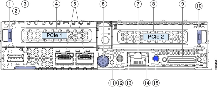
Figure 1. C125 M5 Rear Panel

1

PCIe riser 1 handle

8

PCIe riser 2/slot 2

(half-height, half length, x16 slot)

2

USB 3.0 port

9

KVM local console port

Used with KVM cable that provides one DB-15 VGA, one DB-9 serial, and two USB connectors.

3

Pull-out asset tag

10

PCIe riser 2 handle

4

PCIe riser 1/slot 1

(half-height, half length, x8 slot)

11

Node health LED

5

OCP adapter card Ethernet LAN ports

Depending on which adapter is installed, these ports can be either:

  • Dual 10 Gb Base-T (RJ-45 connectors)

  • Dual 10/25 Gb SFP28 (shown)

  • Single 100 Gb Infiniband/Ethernet

12

Node Power button/Power status LED

Use this button to shut down power to an individual node without powering off the chassis.

6

Node securing thumbscrew and release lever

13

1 Gb Ethernet management port link speed LED

7

1 Gb Ethernet dedicated management port

14

1 Gb Ethernet management port link status LED

-

15

Node locator button/LED

Externally Viewable LEDs

The LEDs below repeat on all nodes. Other LEDs will vary, depending on which adapter cards are installed.

Table 2. C125 M5 Compute Node Externally Viewable LEDs

LED

Definition of States

Node power status button/LED

  • Off—There is no power to the node.

  • Amber—The node is in standby power mode. Power is supplied only to the Cisco IMC.

  • Green—The node is in main power mode. Power is supplied to all node components.

Node locator button/LED

Activating the beacon LED on any installed compute node also activates the locator beacon on the front of the chassis.

  • Off—The locator LED is not activated.

  • Blue, blinking—The locator LED is activated.

Node health LED

  • Green—The node is operating normally.

  • Amber—The node is in a degraded condition (for example, one or more of the following conditions):

    • Faulty or mismatched CPUs

    • DIMM failure

    • Failed drive in a RAID configuration

  • Amber, Blinking—The node is in a critical condition (for example, one or more of the following conditions):

    • Boot failure

    • Fatal CPU and/or bus errors detected

    • Fatal uncorrectable memory errors

    • Excessive thermal conditions

1 Gb Ethernet management port link speed

  • Off—Link speed is 10 Mbps.

  • Amber—Link speed is 100 Mbps.

  • Green—Link speed is 1 Gbps.

1 Gb Ethernet management port link status

  • Off—No link is present.

  • Green—Link is active.

  • Green, Blinking—Traffic is present on the active link.

Local KVM Console Connection

The local console connector allows a direct connection to a node to allow management tasks to be done locally rather than remotely. The port uses the KVM cable N20-BKVM; it has a DB-9 serial connector, a DB-15 VGA connector for a monitor, and dual USB ports for a keyboard and mouse.

Figure 2. KVM Cable for Local Connection

1

Connector to compute node local console connection

2

DB-9 serial connector

3

DB-15 VGA connector for a monitor

4

Two-port USB connector for a mouse and keyboard

C125 M5 Compute Node Internal Component Locations

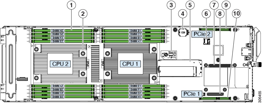
Figure 3. C125 M5 Compute Node Internal Components

1

DIMM sockets (each CPU supports 8 sockets, 16 total)

6

Micro-SD card socket on server board

2

AMD EPYC 7001 Series (Naples) and Second Generation AMD EPYC 7002 Series (Rome) CPUs and heatsinks (one or two)

The front and rear CPUs use different heatsinks.

7

OCP adapter card socket A

OCP adapter cards that require a x8 lane plug into only socket A. OCP cards that require a x16 lane plug into both sockets A and B.

3

Trusted platform module (TPM) location on server board

8

OCP adapter card socket B

OCP adapter cards that require a x8 lane plug into only socket A. OCP cards that require a x16 lane plug into both sockets A and B.

4

Real-time clock (RTC) battery CR2032 horizontal socket location on server board

9

Socket for PCIe riser 2/ PCIe slot 2 (riser not shown in this view)

Riser 2 plugs into a board socket to provide one horizontal PCIe slot (half-height, half length, x16 slot).

5

Mini-storage module socket on server board. Supports:

  • an SD card carrier with two slots for SD cards

  • an M.2 SSD carrier with two slots for M.2 SATA SSDs

  • a Cisco Boot-Optimized M.2 RAID Controller

10

Socket for PCIe riser 1/PCIe slot 1 (riser not shown in the is view)

Riser 1 plugs into this socket to provide one horizontal PCIe slot (half-height, half length, x8 slot).

This is the required slot for a SAS RAID controller. The controller supports the six front-loading drives in the chassis that correspond to the node's position (group 1, 2, 3, or 4).

Riser 1 also includes one x8 Slimline connector for pass-through (JBOD) SATA drive control.

C125 Compute Node Specifications

This topic lists the physical and environmental specifications for the compute node.

Physical Specifications

The following table lists the physical specifications for the C125 compute node.

Table 3. Physical Specifications

Description

Specification

Height

1.59 in (40.39 mm)

Width

6.8 in (172.7 mm)

Depth (length)

22.99 in (583.9 mm)

Weight, fully configured

Fully configured: 9.75 lbs (4.42 kg)

Actual weight depends on which components are installed.

Environmental Specifications

The following table lists the environmental requirements for the C125 compute node.

Table 4. Physical Specifications

Description

Specification

Temperature, Operating

41 to 95°F (5 to 35°C)

Derate the maximum temperature by 1°C per every 305 meters of altitude above sea level.

Temperature, non-operating

(when the server is stored or transported)

–40 to 149°F (–40 to 65°C)

Humidity (RH), operating

10 to 90%

Humidity (RH), non-operating

(when the server is stored or transported)

5 to 93%

Altitude, operating

0 to 10,000 feet

Altitude, non-operating

(when the server is stored or transported)

0 to 40,000 feet