VersaStack with Cisco ACI and IBM SAN Volume Controller Design Guide
Available Languages
VersaStack with Cisco ACI and IBM SAN Volume Controller Design Guide
Cisco ACI, IBM SVC, FlashSystem 9000, and Storwize V5030 with vSphere 6.0U2
Last Updated: April 20, 2017

The CVD program consists of systems and solutions designed, tested, and documented to facilitate faster, more reliable, and more predictable customer deployments. For more information visit
http://www.cisco.com/go/designzone.
ALL DESIGNS, SPECIFICATIONS, STATEMENTS, INFORMATION, AND RECOMMENDATIONS (COLLECTIVELY, "DESIGNS") IN THIS MANUAL ARE PRESENTED "AS IS," WITH ALL FAULTS. CISCO AND ITS SUPPLIERS DISCLAIM ALL WARRANTIES, INCLUDING, WITHOUT LIMITATION, THE WARRANTY OF MERCHANTABILITY, FITNESS FOR A PARTICULAR PURPOSE AND NONINFRINGEMENT OR ARISING FROM A COURSE OF DEALING, USAGE, OR TRADE PRACTICE. IN NO EVENT SHALL CISCO OR ITS SUPPLIERS BE LIABLE FOR ANY INDIRECT, SPECIAL, CONSEQUENTIAL, OR INCIDENTAL DAMAGES, INCLUDING, WITHOUT LIMITATION, LOST PROFITS OR LOSS OR DAMAGE TO DATA ARISING OUT OF THE USE OR INABILITY TO USE THE DESIGNS, EVEN IF CISCO OR ITS SUPPLIERS HAVE BEEN ADVISED OF THE POSSIBILITY OF SUCH DAMAGES.
THE DESIGNS ARE SUBJECT TO CHANGE WITHOUT NOTICE. USERS ARE SOLELY RESPONSIBLE FOR THEIR APPLICATION OF THE DESIGNS. THE DESIGNS DO NOT CONSTITUTE THE TECHNICAL OR OTHER PROFESSIONAL ADVICE OF CISCO, ITS SUPPLIERS OR PARTNERS. USERS SHOULD CONSULT THEIR OWN TECHNICAL ADVISORS BEFORE IMPLEMENTING THE DESIGNS. RESULTS MAY VARY DEPENDING ON FACTORS NOT TESTED BY CISCO.
CCDE, CCENT, Cisco Eos, Cisco Lumin, Cisco Nexus, Cisco StadiumVision, Cisco TelePresence, Cisco WebEx, the Cisco logo, DCE, and Welcome to the Human Network are trademarks; Changing the Way We Work, Live, Play, and Learn and Cisco Store are service marks; and Access Registrar, Aironet, AsyncOS, Bringing the Meeting To You, Catalyst, CCDA, CCDP, CCIE, CCIP, CCNA, CCNP, CCSP, CCVP, Cisco, the Cisco Certified Internetwork Expert logo, Cisco IOS, Cisco Press, Cisco Systems, Cisco Systems Capital, the Cisco Systems logo, Cisco Unity, Collaboration Without Limitation, EtherFast, EtherSwitch, Event Center, Fast Step, Follow Me Browsing, FormShare, GigaDrive, HomeLink, Internet Quotient, IOS, iPhone, iQuick Study, IronPort, the IronPort logo, LightStream, Linksys, MediaTone, MeetingPlace, MeetingPlace Chime Sound, MGX, Networkers, Networking Academy, Network Registrar, PCNow, PIX, PowerPanels, ProConnect, ScriptShare, SenderBase, SMARTnet, Spectrum Expert, StackWise, The Fastest Way to Increase Your Internet Quotient, TransPath, WebEx, and the WebEx logo are registered trademarks of Cisco Systems, Inc. and/or its affiliates in the United States and certain other countries.
All other trademarks mentioned in this document or website are the property of their respective owners. The use of the word partner does not imply a partnership relationship between Cisco and any other company. (0809R)
© 2016 Cisco Systems, Inc. All rights reserved.
Cisco UCS 6200 Series Fabric Interconnects
Cisco UCS 5108 Blade Server Chassis
Cisco UCS Virtual Interface Card 1340
Cisco UCS Virtual Interface Card 1227
Cisco Nexus 9000 based Application Centric Infrastructure
Application Policy Infrastructure Controller (APIC)
ACI 9300 based Spine and Leaf Switches
IBM Storwize V5000 Second Generation
For more information, refer to: http://www.vmware.com/products/vcenter-server/overview.html
Cisco Application Virtual Switch
Cisco Adaptive Security Appliance – ASA
Cisco Unified Computing System
Cisco UCS C-series Server Connectivity
Cisco UCS Server configuration for VSphere
IBM SAN Volume Controller – I/O Groups
IBM SAN Volume Controller – iSCSI Connectivity
IBM SAN Volume Controller - FC Connectivity
IBM SAN Volume Controller – Connectivity to the UCS, FlashSystem 900 and Storwize V5030
In-Band Management VLAN Configuration
Virtual Machine Networking VLANs for VMware vDS
Virtual Machine Networking VLANs for Cisco AVS
VSAN Design for Host to Storage connectivity
Application Centric Infrastructure Design
End Point Group (EPG) Mapping in a VersaStack Environment
Virtual Machine Manager (VMM) Domains
Virtual Switching Architecture
Onboarding Infrastructure Services
Foundation Tenant EPG Design for iSCSI based Storage
Enabling Management Access through Common Tenant
Onboarding Multi-Tier Application
Port Group creation for VMware vDS
Port Group creation for Cisco AVS
External Network Connectivity - Shared Layer 3 Out
Integrating Firewall Services using Network-Only-Stitching (Unmanaged Firewall)
Cisco Unified Computing System I/O Component Selection
Validated I/O Component Configurations
Cisco Unified Computing System Chassis/FEX Discovery Policy
Storage Design and Scalability
Virtual Port Channel Configuration
Distributed Switch – VLAN vs VxLAN encapsulation
Cisco AVS – VxLAN Load Balancing
Compute Scalability Considerations
Compute and Virtualization High Availability Considerations
Deployment Hardware and Software
Hardware and Software Revisions
Cisco Validated Designs (CVDs) deliver systems and solutions that are designed, tested, and documented to facilitate and improve customer deployments. These designs incorporate a wide range of technologies and products into a portfolio of solutions that have been developed to address the business needs of the customers and to guide them from design to deployment.
Customers looking to deploy applications using a shared data center infrastructure face a number of challenges. A recurrent infrastructure challenge is to achieve the required levels of IT agility and efficiency that can effectively meet the company’s business objectives. Addressing these challenges requires having an optimal solution with the following key characteristics:
· Availability: Help ensure applications and services availability at all times with no single point of failure
· Flexibility: Ability to support new services without requiring underlying infrastructure modifications
· Efficiency: Facilitate efficient operation of the infrastructure through re-usable policies
· Manageability: Ease of deployment and ongoing management to minimize operating costs
· Scalability: Ability to expand and grow with significant investment protection
· Compatibility: Minimize risk by ensuring compatibility of integrated components
Cisco and IBM have partnered to deliver a series of VersaStack solutions that enable strategic data center platforms with the above characteristics. VersaStack solution delivers an integrated architecture that incorporates compute, storage and network design best practices thereby minimizing IT risks by validating the integrated architecture to ensure compatibility between various components. The solution also addresses IT pain points by providing documented design guidance, deployment guidance and support that can be used in various stages (planning, designing and implementation) of a deployment.
The Cisco Application Centric Infrastructure (ACI) and IBM SAN Volume Controller (SVC) based VersaStack solution, covered in this CVD, delivers a converged infrastructure platform specifically designed for software defined networking (SDN) enabled data centers. In this deployment, SVC standardizes storage functionality across different arrays and provides a single point of control for virtualized storage. The design showcases:
· Cisco ACI enabled Cisco Nexus 9000 switching architecture
· IBM SVC providing single point of management and control for IBM FlashSystem 900 and IBM Storwize V5030
· Cisco Unified Compute System (UCS) servers with Intel Broadwell processors
· Storage designs supporting both Fibre Channel and iSCSI based storage access
· VMware vSphere 6.0U2 hypervisor
· Cisco MDS Fibre Channel (FC) switches for SAN connectivity
Introduction
VersaStack solution is a pre-designed, integrated and validated architecture for data center that combines Cisco UCS servers, Cisco Nexus family of switches, Cisco MDS fabric switches and IBM Storwize and FlashSystem Storage Arrays into a single, flexible architecture. VersaStack is designed for high availability, with no single points of failure, while maintaining cost-effectiveness and flexibility in the design to support a wide variety of workloads.
VersaStack design can support different hypervisor options, bare metal servers and can also be sized and optimized based on customer workload requirements. VersaStack design discussed in this document has been validated for resiliency (under fair load) and fault tolerance during system upgrades, component failures, and partial as well as total power loss scenarios.
VersaStack with Cisco ACI and IBM SVC solution is designed to simplify the data center evolution to a shared cloud-ready infrastructure based on an application driven policy model. Utilizing the Cisco ACI functionality, the VersaStack platform delivers an application centric architecture with centralized automation that combines software flexibility with the hardware performance. With the addition of IBM SVC to the solution design, storage administrators can now perform system configuration, system management and service tasks in a consistent manner over multiple storage arrays from a single easy-to-use graphical user interface, therefore reducing the risk of inconsistent configuration.
Audience
The intended audience of this document includes, but is not limited to, sales engineers, field consultants, professional services, IT managers, partner engineering, and customers who want to take advantage of an infrastructure built to deliver IT efficiency and enable IT innovation.
What’s New?
The following design elements distinguish this version of VersaStack from previous models:
· Validation of the Cisco ACI release 2.0
· Support for Cisco Tetration ready Nexus 93180YC leaf switches
· Cisco UCS Multi-system validation for added scalability
· Validation of ACI direct-attached Cisco UCS C-Series based dedicated management infrastructure
· IBM SVC 2145-DH8 and 2145-SV1 release 7.7.1.3
· IBM FlashSystem 900 release 1.4.5.0
· IBM Storwize V5030 release 7.7.1.3
· Support for the Cisco UCS release 3.1.2 and updated HTML5 based UCS Manager
· Support for Fiber Chanel storage utilizing Cisco MDS 9396S
· Validation of IP-based storage design supporting iSCSI based storage access
· Application design guidance for multi-tiered application using Cisco ACI application profiles and policies
· Support for application segregation utilizing ACI multi-tenancy
· Integration of Cisco ASA firewall appliance for enhanced application security
For more information on previous VersaStack models, please refer the VersaStack guides at:
VersaStack Program Benefits
Cisco and IBM have carefully validated and verified the VersaStack solution architecture and its many use cases while creating a portfolio of detailed documentation, information, and references to assist customers in transforming their data centers to this shared infrastructure model. This portfolio will include, but is not limited to the following items:
· Architectural design best practice
· Implementation and deployment instructions
· Technical specifications (rules for what is, and what is not, a VersaStack configuration)
· Cisco Validated Designs (CVDs) and IBM Redbooks focused on a variety of use cases
Cisco and IBM have also built a robust and experienced support team focused on VersaStack solutions. The team includes customer account and technical sales representatives as well as professional services and technical support engineers. The support alliance between IBM and Cisco provides customers and channel services partners direct access to technical experts who are involved in cross vendor collaboration and have access to shared lab resources to resolve potential multi-vendor issues.
VersaStack is a data center architecture comprised of the following infrastructure components for compute, network and storage:
· Cisco Unified Computing System (Cisco UCS)
· Cisco Nexus and Cisco MDS Switches
· IBM SAN Volume Controller, IBM FlashSystem and IBM Storwize family storage
These components are connected and configured according to best practices of both Cisco and IBM and provide an ideal platform for running a variety of workloads with confidence. The reference architecture covered in this document leverages:
· Cisco UCS 5108 Blade Server chassis
· Cisco UCS 2200 Series Fabric Extenders (Optional)
· Cisco UCS B-Series Blade servers
· Cisco UCS C-Series Rack Mount servers
· Cisco UCS 6200 Series Fabric Interconnects (FI)
· Cisco Application Policy Infrastructure Controllers (APIC)
· Cisco Nexus 9336 ACI Spine Switches
· Cisco Nexus 93180YC ACI Leaf Switches
· Cisco MDS 9396S Fabric Switches
· IBM SAN Volume Controller (SVC) 2145-DH8 and 2145-SV1 nodes*
· IBM FlashSystem 900
· IBM Storwize V5030
· VMware vSphere 6.0 Update 2
* This design guide showcases two IBM 2145-DH8 and two 2145-SV1 nodes setup as a four node cluster. This configuration can be customized for customer specific deployments.
Figure 1 VersaStack with Cisco ACI and IBM SVC – Components
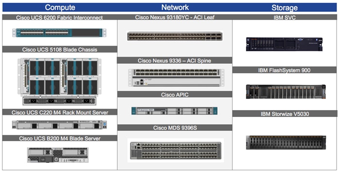
One of the key benefits of VersaStack is the ability to maintain consistency at both scale up and scale down models. VersaStack can scale up for greater performance and capacity. In other words, you can add compute, network, or storage resources as needed; or it can also scale out where you need multiple consistent deployments like rolling out additional VerstaStack modules. Each of the component families shown in Figure 1 (Cisco Unified Computing System, Cisco Switches, and IBM storage arrays) offer platform and resource options to scale the infrastructure up or down while supporting the same features and functionality.
The following sub-sections provide a technical overview of the compute, network, storage and management components of the VersaStack solution.
Cisco Unified Compute System
The Cisco Unified Computing System (UCS) is a next-generation data center platform that integrates computing, networking, storage access, and virtualization resources into a cohesive system designed to reduce total cost of ownership (TCO) and to increase business agility. The system integrates a low-latency; lossless 10 Gigabit Ethernet unified network fabric with enterprise-class, x86-architecture servers. The system is an integrated, scalable, multi-chassis platform where all resources are managed through a unified management domain.
The Cisco Unified Computing System in the VersaStack architecture utilizes the following components:
· Cisco UCS Manager (UCSM) provides unified management of all software and hardware components in the Cisco UCS to manage servers, networking, and storage configurations. The system uniquely integrates all the system components, enabling the entire solution to be managed as a single entity through Cisco UCSM software. Customers can interface with Cisco UCSM through an intuitive graphical user interface (GUI), a command-line interface (CLI), and a robust application-programming interface (API) to manage all system configuration and operations.
· Cisco UCS 6200 Series Fabric Interconnects is a family of line-rate, low-latency, lossless, 10-Gbps Ethernet, Fibre Channel and Fibre Channel over Ethernet interconnect switches providing the management and communication backbone for the Cisco UCS. The unified fabric lowers costs by reducing the number of network adapters, switches, and cables, and by decreasing the power and cooling requirements.
· Cisco UCS 5108 Blade Server Chassis supports up to eight blade servers and up to two fabric extenders in a six-rack unit (RU) enclosure.
· Cisco UCS B-Series Blade Servers provide performance, efficiency, versatility and productivity with the latest Intel based processors.
· Cisco UCS C-Series Rack Mount Servers deliver unified computing innovations and benefits to rack servers with performance and density to support a wide range of workloads.
· Cisco UCS Network Adapters provide wire-once architecture and offer a range of options to converge the fabric, optimize virtualization and simplify management.
Cisco UCS Management
Cisco’s Unified Compute System has revolutionized the way servers are managed in the data center. Some of the unique differentiators of Cisco UCS and Cisco UCS Manager are:
· Embedded Management —In Cisco UCS, the servers are managed by the embedded firmware in the Fabric Interconnects, eliminating need for any external physical or virtual devices to manage the servers.
· Auto Discovery —By simply inserting the blade server in the chassis or connecting rack server to the fabric interconnect, discovery and inventory of compute resource occurs automatically without any management intervention.
· Policy Based Resource Classification —Once the compute resource is discovered by Cisco UCS Manager, it can be automatically classified based on defined policies. This capability is useful in multi-tenant cloud computing.
· Combined Rack and Blade Server Management —Cisco UCS Manager can manage B-series blade servers and C-series rack server under the same Cisco UCS domain. This feature, along with stateless computing makes compute resources truly hardware form factor agnostic.
· Model based Management Architecture —Cisco UCS Manager architecture and management database is model based and data driven. An open XML API is provided to operate on the management model. This enables easy and scalable integration of Cisco UCS Manager with other management systems.
· Service Profiles and Stateless Computing —A service profile is a logical representation of a server, carrying its various identities and policies. Stateless computing enables procurement of a server within minutes compared to days in legacy server management systems.
· Policies, Pools, Templates —The management approach in Cisco UCS Manager is based on defining policies, pools and templates, instead of cluttered configuration, which enables a simple, loosely coupled, data driven approach in managing compute, network and storage resources.
· Built-in Multi-Tenancy Support —The combination of policies, pools and templates, organization hierarchy and a service profiles based approach to compute resources makes Cisco UCS Manager inherently friendly to multi-tenant environment typically observed in private and public clouds.
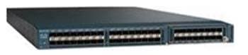
Cisco UCS 6200 Series Fabric Interconnects
The Cisco UCS Fabric interconnects (FI) provide a single point for connectivity and management for the entire system by integrating all compute components into a single, highly available management domain controlled by Cisco UCS Manager. Cisco UCS FIs support the system’s unified fabric with low-latency, lossless, cut-through switching that supports IP, storage, and management traffic using a single set of cables. Cisco UCS FIs are typically deployed in redundant pairs. The Cisco UCS 6248UP model utilized in this CVD is a 1-RU form factor that features up to 48 universal ports that can support 10 Gigabit Ethernet or Fibre Channel over Ethernet, or 8/4/2 native Fibre Channel connectivity.
Figure 2 Cisco UCS 6248UP Fabric Interconnect
|
|
|
For more information on various models of the Cisco UCS 6200 Fabric Interconnect, visit http://www.cisco.com/c/en/us/products/servers-unified-computing/ucs-6200-series-fabric-interconnects/index.html
![]() Latest generation of Cisco UCS 6300 Fabric Interconnect is not covered in this design guide.
Latest generation of Cisco UCS 6300 Fabric Interconnect is not covered in this design guide.
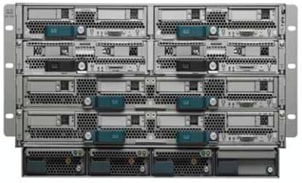
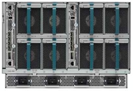
Cisco UCS 5108 Blade Server Chassis
The Cisco UCS 5108 Blade Server Chassis is a fundamental building block of the Cisco Unified Computing System, delivering scalable and flexible blade server architecture. A Cisco UCS 5108 Blade Server chassis is six rack units (6RU) high and can house up to eight half-width or four full-width Cisco UCS B-series blade servers.
For a complete list of blade servers supported, see: http://www.cisco.com/c/en/us/products/servers-unified-computing/ucs-b-series-blade-servers/index.html
The Cisco UCS 5108 chassis contains two I/O bays in the rear that can support Cisco UCS 2200 Series Fabric Extenders. The two fabric extenders can be used for both redundancy and bandwidth aggregation. A passive mid-plane provides up to 80Gbps of I/O bandwidth per server slot and up to 160Gbps of I/O bandwidth for two slots (full width) blades. The chassis is also capable of supporting 40Gigabit Ethernet. Cisco UCS 5108 blade server chassis uses a unified fabric and fabric-extender technology to simplify and reduce cabling by eliminating the need for dedicated chassis management and blade switches. The unified fabric also reduces TCO by reducing the number of network interface cards (NICs), host bus adapters (HBAs), switches, and cables that need to be managed, cooled, and powered. This architecture enables a single Cisco UCS domain to scale up to 20 chassis with minimal complexity.
For more information, see:
http://www.cisco.com/c/en/us/products/servers-unified-computing/ucs-5100-series-blade-server-chassis/index.html
Figure 3 Cisco UCS 5108 Blade Server Chassis
|
|
|
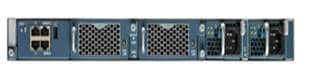
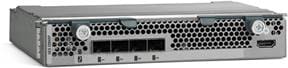
Cisco UCS 2200 Series Fabric Extenders
The Cisco UCS 2200 Series Fabric Extender multiplexes and forwards all traffic from servers in a chassis to a parent Cisco UCS Fabric Interconnect over from 10-Gbps unified fabric links. All traffic, including traffic between servers on the same chassis, or between virtual machines on the same server, is forwarded to the parent fabric interconnect, where network profiles and polices are maintained and managed by the Cisco UCS Manager. Up to two fabric extenders can be deployed in a Cisco UCS chassis. The Cisco UCS 2200 Series Fabric Extenders come in two flavors:
· The Cisco UCS 2204XP Fabric Extender has four 10 Gigabit Ethernet, FCoE-capable, SFP+ ports that connect the blade chassis to the fabric interconnect. Each Cisco UCS 2204XP has sixteen 10 Gigabit Ethernet ports connected through the mid-plane to each half-width slot in the chassis. Typically configured in pairs for redundancy, two fabric extenders provide up to 80Gbps of I/O to the chassis.
· The Cisco UCS 2208XP Fabric Extender has eight 10 Gigabit Ethernet, FCoE-capable, SFP+ ports that connect the blade chassis to the fabric interconnect. Each Cisco UCS 2208XP has thirty-two 10 Gigabit Ethernet ports connected through the mid-plane to each half-width slot in the chassis. Typically configured in pairs for redundancy, two fabric extenders provide up to 160Gbps of I/O to the chassis.
For more information, see: http://www.cisco.com/c/en/us/products/collateral/servers-unified-computing/ucs-6200-series-fabric-interconnects/data_sheet_c78-675243.html
Figure 4 Cisco UCS 2204XP Fabric Extender
![]() Latest generation of Cisco UCS 2300 Fabric Extenders is not covered in this design guide.
Latest generation of Cisco UCS 2300 Fabric Extenders is not covered in this design guide.
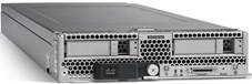
Cisco UCS B200 M4 Servers
The enterprise-class Cisco UCS B200 M4 Blade Server extends the capabilities of Cisco’s Unified Computing System portfolio in a half-width blade form factor. The Cisco UCS B200 M4 uses the power of the latest Intel® Xeon® E5-2600 v3 and v4 series processor family CPUs providing up to 44 processing cores, up to 1536 GB of RAM (using 64 GB DIMMs), two solid-state drives (SSDs) or hard disk drives (HDDs), and up to 80Gbps throughput connectivity. The Cisco UCS B200 M4 Blade Server mounts in a Cisco UCS 5100 Series blade server chassis or Cisco UCS Mini blade server chassis. It has 24 total slots for registered ECC DIMMs (RDIMMs) or load-reduced DIMMs (LR DIMMs) for up to 1536 GB total memory capacity. It supports one connector for Cisco’s VIC 1340 or 1240 adapter, which provides Ethernet and FCoE connectivity.
For more information, see: http://www.cisco.com/c/en/us/products/servers-unified-computing/ucs-b200-m4-blade-server/index.html
Figure 5 Cisco UCS B200 M4 Blade Server
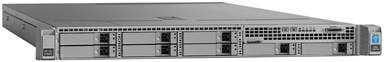
Cisco UCS C220 M4 Servers
The enterprise-class Cisco UCS C220 M4 server extends the capabilities of the Cisco Unified Computing System (UCS) portfolio in a one rack-unit (1RU) form-factor. The Cisco UCS C220 M4 uses the power of the latest Intel® Xeon® E5-2600 v3 and v4 Series processor family CPUs with up to 1536 GB of RAM (using 64 GB DIMMs), 8 Small Form-Factor (SFF) drives or 4 Large Form-Factor (LFF) drives, and up to 80Gbps throughput connectivity. The Cisco UCS C220 M4 Rack Server can be used standalone, or as integrated part of the Unified Computing System. It has 24 DIMM for up to 1536 GB total memory capacity. It supports one connector for the Cisco VIC 1225, 1227 or 1380 adapters, which provide Ethernet and FCoE.
For more information, see: http://www.cisco.com/c/en/us/products/collateral/servers-unified-computing/ucs-c220-m4-rack-server/datasheet-c78-732386.html
Figure 6 Cisco UCS C220 M4 Rack Server
Cisco UCS Network Adapters
The Cisco Unified Computing System supports converged network adapters (CNAs) to provide connectivity to the blade and rack mount servers. CNAs obviate the need for multiple network interface cards (NICs) and host bus adapters (HBAs) by converging LAN and SAN traffic in a single interface. While Cisco UCS supports wide variety of interface cards, this CVD utilizes following two models: Cisco Virtual Interface Card (VIC) 1340 and Cisco VIC 1227. Further discussion around Cisco UCS adapters will be limited to these two models.
Cisco UCS Virtual Interface Card 1340
The Cisco UCS Virtual Interface Card (VIC) 1340 is a 2-port 40Gbps Ethernet or dual 4 x 10-Gbps Ethernet, FCoE-capable modular LAN on motherboard (mLOM) designed exclusively for the M4 generation of Cisco UCS B-Series Blade Servers. The Cisco 1340 VIC supports an optional port-expander which enables the 40-Gbps Ethernet capabilities of the card. The Cisco UCS VIC 1340 supports a policy- based, stateless, agile server infrastructure that can present over 256 PCIe standards-compliant interfaces to the host that can be dynamically configured as either network interface cards (NICs) or host bus adapters (HBAs). In addition, the Cisco UCS VIC 1340 supports Cisco Virtual Machine Fabric Extender (VM-FEX) technology, which extends the Cisco UCS Fabric interconnect ports to virtual machines, simplifying server virtualization deployment and management.
For more information, see: http://www.cisco.com/c/en/us/products/interfaces-modules/ucs-virtual-interface-card-1340/index.html
Figure 7 Cisco VIC 1340
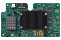
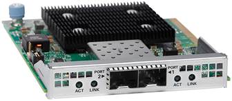
Cisco UCS Virtual Interface Card 1227
The Cisco UCS VIC 1227 is a dual-port Enhanced Small Form-Factor Pluggable (SFP+) 10-Gbps Ethernet and FCoE-capable PCI Express (PCIe) mLOM adapter designed exclusively for Cisco UCS C-Series Rack Servers. The mLOM slot can be used to install a Cisco VIC without consuming a PCIe slot, which provides greater I/O expandability. Just like Cisco UCS VIC 1340, the Cisco UCS VIC 1227 enables a policy-based, stateless, agile server infrastructure that can present up to 256 PCIe standards-compliant interfaces to the host that can be dynamically configured as either NICs or HBAs. The Cisco UCS VIC 1227 also supports VM-FEX technology, which extends the Cisco UCS fabric interconnect ports to virtual machines, simplifying server virtualization deployment.
For more information, see: http://www.cisco.com/c/en/us/products/interfaces-modules/ucs-virtual-interface-card-1227/index.html
Figure 8 Cisco VIC 1227
Cisco Nexus 9000 based Application Centric Infrastructure
The Cisco Nexus 9000 family of switches supports two modes of operation: NX-OS standalone mode and Application Centric Infrastructure (ACI) fabric mode. In standalone mode, the switch performs as a typical Cisco Nexus switch with increased port density, low latency and 40Gbps connectivity. In fabric mode, the administrator can take advantage of Cisco Application Centric Infrastructure (ACI).
Cisco ACI is a new data center architecture designed to address the requirements of today’s traditional networks, as well as to meet emerging demands that new computing trends and business factors are placing on the network. Software-defined networking (SDN) has garnered much attention in the networking industry over the past few years due to its promise of a more agile and programmable network infrastructure. Cisco ACI not only addresses the challenges of agility and network programmability that software-based overlay networks are trying to address, but it also presents solutions to the new challenges that SDN technologies are currently unable to address.
Cisco ACI leverages a network fabric that employs industry proven protocols coupled with innovative technologies to create a flexible, scalable, and highly available architecture of low-latency, high-bandwidth links. This fabric delivers application instantiations using profiles that house the requisite characteristics to enable end-to-end connectivity. The ACI fabric is designed to support the management automation, programmatic policies, and dynamic workload provisioning. The ACI fabric accomplishes this with a combination of hardware, policy-based control systems, and closely coupled software to provide advantages not possible in other vendor solutions.
Figure 9 Cisco ACI - High Level Architecture
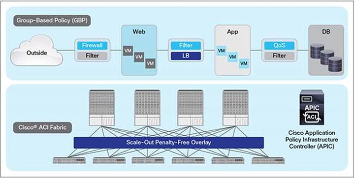
The ACI switching architecture is presented in a leaf-and-spine topology where every leaf connects to every spine using 40G Ethernet interfaces. At a high-level, the Cisco ACI fabric consists of three major components:
· The Application Policy Infrastructure Controller (APIC)
· Spine switches
· Leaf switches
Cisco Nexus 9000-based VersaStack design with Cisco ACI consists of Cisco Nexus 9336 PQ based spine and Cisco 93180YC-EX based leaf switching architecture controlled using a cluster of three Application Policy Infrastructure Controllers (APICs).
Figure 10 VersaStack ACI Design

Application Policy Infrastructure Controller (APIC)
The software controller, APIC, is delivered as an appliance and three or more such appliances form a cluster for high availability and enhanced performance. APIC is responsible for all tasks enabling traffic transport including fabric activation, switch firmware management and network policy configuration and instantiation. Though the APIC acts as the centralized point of configuration for policy and network connectivity, it is never in-line with the data path or the forwarding topology and the fabric can still forward traffic even when communication with the APIC is disrupted. APIC provides both a command-line interface (CLI) and graphical-user interface (GUI) to configure and control the ACI fabric. APIC also exposes a northbound API through XML and JavaScript Object Notation (JSON) and an open source southbound API.
ACI 9300 based Spine and Leaf Switches
The Cisco Nexus 9300 Series Switches include both spine and leaf switches. Cisco Nexus 9300 platform leaf switches are Layer 2 and 3 non-blocking 10 and 40 Gigabit Ethernet switches with up to 2.56 terabits per second (Tbps) of internal bandwidth.
Cisco Nexus 9336 PQ Spine
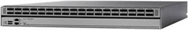
The Cisco Nexus 9336PQ ACI Spine Switch is a 2-rack-unit (2RU) spine switch for Cisco ACI that supports 2.88Tbps of bandwidth across 36 fixed 40 QSFP+ ports as shown in Figure 11.
Figure 11 Cisco Nexus 9336 PQ Switch
Cisco Nexus 93180YC-EX Leaf
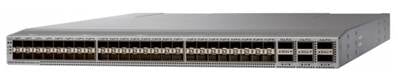
The Cisco Nexus 93180YC-EX Switch are 1RU switches that support 48 10/25-Gbps Small Form Pluggable Plus (SFP+) ports and 6 40/100-Gbps Quad SFP+ (QSFP+) uplink ports. All ports are line rate, delivering 3.6Tbps of throughput. The switch supports Cisco Tetration Analytics Platform with built-in hardware sensors for rich traffic flow telemetry and line-rate data collection.
Figure 12 Cisco Nexus 93180YC-EX Switch
For detailed information on the Cisco Nexus 9000 product line, refer to http://www.cisco.com/c/en/us/products/switches/nexus-9000-series-switches/models-listing.html
Cisco MDS 9396S Fabric Switch
The Cisco MDS 9396S 16G Multilayer Fabric Switch is the next generation of the highly reliable, flexible, and affordable Cisco MDS 9000 Family fabric switches. This powerful, compact, 2-rack-unit switch scales from 48 to 96 line-rate 16-Gbps Fibre Channel ports in 12 port increments. Cisco MDS 9396S is powered by Cisco NX-OS and delivers advanced storage networking features and functions with ease of management and compatibility with the entire Cisco MDS 9000 Family portfolio for reliable end-to-end connectivity. Cisco MDS 9396S provides up to 4095 buffer credits per group of 4 ports and supports some of the advanced functions such as Virtual SAN (VSAN), Inter-VSAN routing (IVR), port-channels and multipath load balancing and flow-based and zone-based QoS.
Figure 13 Cisco MDS 9396S

For more information, refer to: http://www.cisco.com/c/en/us/products/storage-networking/mds-9000-series-multilayer-switches/index.html
IBM Spectrum Virtualize
IBM Spectrum Virtualize™ provides an ideal way to manage and protect the huge volumes of data organizations use for big-data analytics and new cognitive workloads. It is a proven offering that has been available for years in IBM SAN Volume Controller (SVC), the IBM Storwize® family of storage solutions, IBM FlashSystem® V9000 and IBM VersaStack™—with more than 130,000 systems running IBM Spectrum Virtualize. These systems are delivering better than five nines of availability while managing more than 5.6 exabytes of data.
IBM Spectrum Virtualize Software V7.7.1 includes the following key improvements:
· Reliability, availability, and serviceability with NPIV host port fabric virtualization, Distributed RAID support for encryption, and IP Quorum in GUI
· Scalability with support for up to 10,000 virtual disks, depending on the model; and up to 20 Expansion Enclosures on SVC DH8 and SV1 models and on FlashSystem V9000
· Manageability with CLI support for host groups
· Virtualization of iSCSI-attached external storage arrays including XIV(R) Gen 3, Spectrum Accelerate, FlashSystem A9000 and FlashSystems A9000R arrays.
· Performance with 64 GB read cache
· Data economics with Comprestimator in the GUI
· Licensing of compression formally added to the External Virtualization software package of Storwize V5030
· Software licensing metrics to better align the value of SVC software with Storage use cases through Differential Licensing
Key existing functions of IBM Spectrum Virtualize include:
· Virtualization of Fibre Channel-attached external storage arrays with support for almost 370 different brands and models of block storage arrays, including arrays from competitors
· Manage virtualized storage as a single storage pool, integrating "islands of storage" and easing the management and optimization of the overall pool
· Real-time Compression™ for in-line, real-time compression to improve capacity utilization
· Virtual Disk Mirroring for two redundant copies of LUN and higher data availability
· Stretched Cluster and HyperSwap® for high availability among physically separated data centers
· Easy Tier® for automatic and dynamic data tiering
· Distributed RAID for better availability and faster rebuild times
· Encryption to help improve security of internal and externally virtualized capacities
· FlashCopy® snapshots for local data protection
· Remote Mirror for synchronous or asynchronous remote data replication and disaster recovery through both Fibre Channel and IP ports with offerings that utilize IBM Spectrum Virtualize software
· Clustering for performance and capacity scalability
· Online, transparent data migration to move data among virtualized storage systems without disruptions
· Common look and feel with other offerings that utilize IBM Spectrum Virtualize software
· IP Link compression to improve usage of IP networks for remote-copy data transmission
More information can be found on the IBM Spectrum Virtualize website:
http://www-03.ibm.com/systems/storage/spectrum/virtualize/index.html
IBM SAN Volume Controller
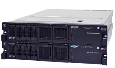
IBM SAN Volume Controller (SVC), is a combined hardware and software storage virtualization system with a single point of control for storage resources. SVC includes many functions traditionally deployed separately in disk systems and by including these in a virtualization system, SVC standardizes functions across virtualized storage for greater flexibility and potentially lower costs.
Figure 14 IBM SAN Volume Controller
Built with IBM Spectrum Virtualize™ software—part of the IBM Spectrum Storage™ family—SVC helps organizations achieve better data economics by supporting the new workloads that are critical to company’s success. SVC systems can handle the massive volumes of data from mobile and social applications, enable rapid and flexible cloud services deployments, and deliver the performance and scalability needed to gain insights from the latest analytics technologies.
Figure 15 IBM SVC – Easy to use Graphical User Interface
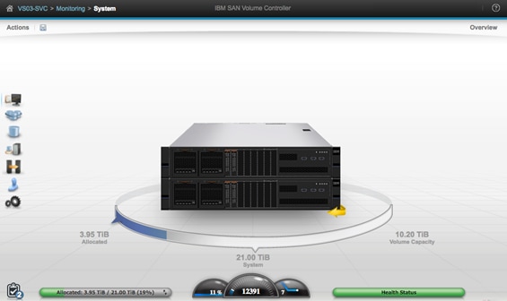
IBM SVC provides an easy-to-use graphical interface for centralized management. With this single interface, administrators can perform configuration, management and service tasks in a consistent manner over multiple storage systems—even from different vendors—vastly simplifying management and helping reduce the risk of errors. IT staff can also use built-in monitoring capabilities to securely check the health and performance of the system remotely from a mobile device. In addition, plug-ins to support VMware vCenter help enable more efficient, consolidated management in these environments.
With the addition of the latest Storage Engine Model SV1, SVC delivers increased performance and additional internal storage capacity. Model SV1 consists of two Xeon E5 v4 Series eight-core processors and 64 GB of memory. It includes 10 Gb Ethernet ports standard for 10 Gb iSCSI connectivity and service technician use, and supports up to four I/O adapter cards for 16 Gb FC and 10 Gb iSCSI/FCoE connectivity. It also includes two integrated AC power supplies and battery units.
SVC Storage Engines, or ‘nodes’, can be clustered to help deliver greater performance, bandwidth, scalability, and availability. An SVC clustered system can contain up to four node pairs or I/O groups. Model SV1 storage engines can be added into existing SVC clustered systems that include previous generation storage engine models such as 2145-DH8.
In summary, SVC combines a variety of IBM technologies to:
· Enhance storage functions, economics and flexibility with sophisticated virtualization
· Leverage hardware-accelerated data compression for efficiency and performance
· Store up to five times more active data using IBM® Real- time Compression™
· Move data among virtualized storage systems without disruptions
· Optimize tiered storage—including flash storage—automatically with IBM Easy Tier®
· Improve network utilization for remote mirroring and help reduce costs
· Implement multi-site configurations for high availability and data mobility
More SVC product information is available on the IBM SAN Volume Controller website: http://www-03.ibm.com/systems/storage/software/virtualization/svc/
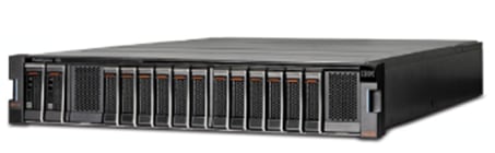
IBM FlashSystem 900
IBM® FlashSystem™ 900 is a fully optimized, all flash storage array designed to accelerate the applications that drive business. Featuring IBM FlashCore™ technology, FlashSystem 900 delivers the high performance, ultra-low latency, enterprise reliability and superior operational efficiency required for gaining competitive advantage in today’s dynamic marketplace.
Figure 16 IBM FlashSystem 900
FlashSystem 900 is composed of up to 12 MicroLatency modules—massively parallel flash arrays that can provide nearly 40 percent higher storage capacity densities than previous FlashSystem models. FlashSystem 900 can scale usable capacity from as low as 2 TB to as much as 57 TB in a single system. MicroLatency modules also support an offload AES-256 encryption engine, high-speed internal interfaces, and full hot-swap and storage capacity scale-out capabilities, enabling organizations to achieve lower cost per capacity with the same enterprise reliability.
Key features include:
· Accelerate critical applications, support more concurrent users, speed batch processes and lower virtual desktop costs with the extreme performance of IBM® FlashCore™ technology
· Harness the power of data with the ultra-fast response times of IBM MicroLatency™
· Leverage macro efficiency for high storage density, low power consumption and improved resource utilization
· Protect critical assets and boost reliability with IBM Variable Stripe RAID™, redundant components and concurrent code loads
· Power faster insights with hardware accelerated architecture, MicroLatency modules and advanced flash management capabilities of FlashCore technology
To read more about FlashSystem 900 on the web, visit: ibm.com/storage/flash/900
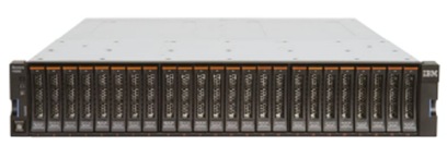
IBM Storwize V5000 Second Generation
Designed for software-defined environments and built with IBM Spectrum Virtualize software, the IBM Storwize family is an industry-leading solution for storage virtualization that includes technologies to complement and enhance virtual environments, delivering a simpler, more scalable, and cost-efficient IT infrastructure.
Storwize V5000 is a highly flexible, easy to use, virtualized hybrid storage system designed to enable midsized organizations to overcome their storage challenges with advanced functionality. Storwize V5000 second-generation models offer improved performance and efficiency, enhanced security, and increased scalability with a set of three models to deliver a range of performance, scalability, and functional capabilities.
Storwize V5000 second-generation offer three hybrid models – IBM Storwize V5030, IBM Storwize V5020 and IBM Storwize V5010 – providing the flexibility to start small and keep growing while leveraging existing storage investments. To enable organizations with midsized workloads achieve advanced performance, IBM Storwize V5030F provides an all-flash solution at an affordable price. In this Design Guide, an IBM Storwize V5030 hybrid model was deployed and validated.
Figure 17 IBM Storwize V5030
Storwize V5030 control enclosure models offer:
· Two 6-core processors and up to 64 GB of cache
· Support for 760 drives (1,008 drives with a two-way clustered configuration) per system with the attachment of 20 Storwize V5000 expansion enclosures or 8 High Density expansion enclosures.
· External virtualization to consolidate and provide Storwize V5000 capabilities to existing storage infrastructures
· Real-time Compression for improved storage efficiency
· Encryption of data at rest stored within the Storwize V5000 system and externally virtualized storage systems
All Storwize V5000 second-generation control enclosures include:
· Dual-active, intelligent node canisters with mirrored cache
· Ethernet ports for iSCSI connectivity
· Support for 16 Gb FC, 12 Gb SAS, 10 Gb iSCSI/FCoE, and 1 Gb iSCSI for additional I/O connectivity
· Twelve 3.5-inch (LFF) drive slots or twenty-four 2.5-inch (SFF) drive slots within the 2U, 19-inch rack mount enclosure
· Support for the attachment of second-generation Storwize V5000 LFF and SFF 12 Gb SAS expansion enclosures
· Support for a rich set of IBM Spectrum Virtualize functions including thin provisioning, IBM Easy Tier, FlashCopy, and remote mirroring
· Either 100-240 V AC or -48 V DC power supplies
· Either a one- or three-year warranty with customer replaceable units (CRU) and on-site service
All Storwize V5000 functional capabilities are provided through IBM Spectrum Virtualize Software for Storwize V5000. For additional information about Storwize V5000 functional capabilities and software, refer to the IBM Storwize V5000 website: http://www-03.ibm.com/systems/uk/storage/disk/storwize_v5000/index.html
VMware vCenter Server
VMware vCenter is the simplest and most efficient way to manage VMware vSphere hosts at scale. It provides unified management of all hosts and virtual machines from a single console and aggregates performance monitoring of clusters, hosts, and virtual machines. VMware vCenter Server gives administrators a deep insight into the status and configuration of compute clusters, hosts, virtual machines, storage, the guest OS, and other critical components of a virtual infrastructure. A single administrator can manage 100 or more virtualization environment workloads using VMware vCenter Server, more than doubling the typical productivity in managing physical infrastructure. VMware vCenter manages the rich set of features available in a VMware vSphere environment.
For more information, refer to: http://www.vmware.com/products/vcenter-server/overview.html
Cisco Application Virtual Switch
Cisco Application Virtual Switch (AVS) is a hypervisor-resident virtual network switch that is specifically designed for the ACI architecture. Based on the Cisco Nexus 1000V virtual switch, Cisco AVS provides feature support for the ACI application policy model, full switching capabilities, and more advanced telemetry features. Instead of using hypervisor-specific management stations, Cisco AVS provides cross-consistency in features, management, and control directly through Cisco APIC. Some of the key features of Cisco AVS include:
· A purpose-built, virtual network edge for ACI fabric architecture
· Integration with the ACI management and orchestration platform to automate virtual network provisioning and application services deployments
· Integrated visibility of both physical and virtual workloads and network paths
· Open APIs to extend the software-based control and orchestration of the virtual network fabric
· Optimal traffic steering to application services and seamless workload mobility
· Support for a consistent operational model across multiple hypervisors for simplified operations in heterogeneous data centers
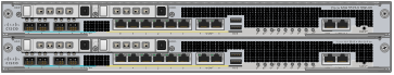
Cisco Adaptive Security Appliance – ASA
The Cisco ASA Family of security devices protects corporate networks and data centers of all sizes. Cisco ASA delivers enterprise-class firewall capabilities for ASA devices in an array of form factors. ASA Software also integrates with other critical security technologies to deliver comprehensive solutions that meet continuously evolving security needs. Cisco ASA delivers high availability for high resiliency applications thereby meeting the unique requirements in the data center. Cisco ASA supports multiple contexts for a multi-tenant deployment. This design guide uses Cisco ASA 5585 platform (shown in Figure 18) to provide firewall functionality.
Figure 18 Cisco ASA 5585
VersaStack with Cisco ACI and IBM SVC architecture aligns with the converged infrastructure configurations and best practices as identified in the previous VersaStack releases. The system includes hardware and software compatibility support between all components and aligns to the configuration best practices for each of these components. All the core hardware components and software releases are listed and supported on both the Cisco compatibility list:
http://www.cisco.com/en/US/products/ps10477/prod_technical_reference_list.html
and IBM Interoperability Matrix:
http://www-03.ibm.com/systems/support/storage/ssic/interoperability.wss
The system supports high availability at network, compute and storage layers such that no single point of failure exists in the design. The system utilizes 10 and 40Gbps Ethernet jumbo-frame based connectivity combined with port aggregation technologies such as virtual port-channels (VPC) for non-blocking LAN traffic forwarding. A dual SAN 8/16Gbps environment provides redundant storage access from compute devices to the storage controllers.
The VersaStack data center with Cisco ACI and IBM SVC solution, as covered in this design guide, conforms to a number of key design and functionality requirements. Some of the key features of the solution are highlighted below.
· The system is able to tolerate the failure of compute, network or storage components without significant loss of functionality or connectivity
· The system is built with a modular approach thereby allowing customers to easily add more network (LAN or SAN) bandwidth, compute power or storage capacity as needed
· The system supports stateless compute design thereby reducing time and effort required to replace or add new compute nodes
· The system provides network automation and orchestration capabilities to the network administrators using Cisco APIC GUI, CLI and restful API
· The systems allow the compute administrators to instantiate and control application Virtual Machines (VMs) from VMware vCenter
· The system provides storage administrators a single point of control to easily provision and manage the storage using IBM management GUI
· The solution supports live VM migration between various compute nodes and protects the VM by utilizing VMware HA and DRS functionality
· The system can be easily integrated with optional Cisco (and third party) orchestration and management application such as Cisco UCS Central and Cisco UCS Director
· The system showcases layer-3 connectivity to the existing enterprise network and provides firewall based system security by utilizing Cisco Adaptive Security Appliance (ASA)
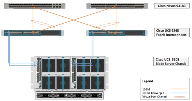
Physical Topology
This VersaStack with Cisco ACI and IBM SVC solution utilizes Cisco UCS platform with Cisco B200 M4 half-width blades and Cisco UCS C220 M4 rack mount servers connected and managed through Cisco UCS 6248 Fabric Interconnects and the integrated Cisco UCS manager. These high performance servers are configured as stateless compute nodes where ESXi 6.0 U1b hypervisor is loaded using SAN (iSCSI and FC) boot. The boot disks to store ESXi hypervisor image and configuration along with the block and file based datastores to host application Virtual Machines (VMs) are provisioned on the IBM storage devices.
As in the non-ACI designs of VersaStack, link aggregation technologies play an important role in VersaStack with ACI solution providing improved aggregate bandwidth and link resiliency across the solution stack. Cisco UCS, and Cisco Nexus 9000 platforms support active port channeling using 802.3ad standard Link Aggregation Control Protocol (LACP). In addition, the Cisco Nexus 9000 series features virtual Port Channel (vPC) capability which allows links that are physically connected to two different Cisco Nexus devices to appear as a single "logical" port channel. Each Cisco UCS Fabric Interconnect (FI) is connected to both the Cisco Nexus 93180 leaf switches using virtual port-channel (vPC) enabled 10GbE uplinks for a total aggregate system bandwidth of 40GBps. Additional ports can be easily added to the design for increased throughput. Each Cisco UCS 5108 chassis is connected to the UCS FIs using a pair of 10GbE ports from each IO Modules for a combined 40GbE uplink. Each of the Cisco UCS C-220 servers connect directly into each of the UCS FIs using a 10Gbps converged link for an aggregate bandwidth of 20Gbps per server.
To provide the compute to storage system connectivity, this design guides highlights two different storage connectivity options:
· Option 1: iSCSI based storage access through Cisco ACI Fabric
· Option 2: FC based storage access through Cisco MDS 9396S
![]() While storage access from the Cisco UCS compute nodes to IBM SVC storage nodes can be iSCSI or FC based, SVC nodes, FS900, and V5030 communicate with each other on Cisco MDS 9396S based FC SAN fabric only.
While storage access from the Cisco UCS compute nodes to IBM SVC storage nodes can be iSCSI or FC based, SVC nodes, FS900, and V5030 communicate with each other on Cisco MDS 9396S based FC SAN fabric only.
The solution also showcases two stand-alone (not managed through UCS Manager) Cisco UCS C220 M4 rack servers configured as a dedicated management cluster to support core infrastructure service virtual machines (VM) such as vCenter, Active Directory, UCS performance manager etc. These Cisco UCS C220 servers are configured to boot ESXi hypervisor from internal storage using FlexFlash Secure Digital cards and are connected directly to Cisco Nexus 93180YC leaf switches. The network configuration allows iSCSI based shared storage access from the management cluster to the IBM SVC for VM deployment.
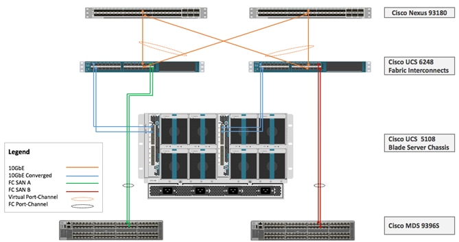
Figure 19 below provides a high level topology of the system connectivity. The VersaStack infrastructure satisfies the high-availability design requirements and is physically redundant across the network, compute and storage stacks. The integrated compute stack design presented in this document can withstand failure of one or more links as well as the failure of one or more devices.
IBM SVC nodes, IBM FlashSystem 900 and IBM Storwize V5030 are all connected using a Cisco MDS 9396S based redundant FC fabric. To provide FC based storage access to the compute nodes, Cisco UCS Fabric Interconnects are connected to the same pair of Cisco MDS 9396S switches and zoned appropriately. To provide iSCSI based storage access, IBM SVC is connected directly to the Cisco Nexus 93180 leaf switches. A10GbE port from each IBM SVC node is connected to each of the two Cisco Nexus 93180 leaf switches providing an aggregate bandwidth of 40Gbps.
![]() Based on the customer requirements, the compute to storage connectivity in the SVC solution can be deployed as an FC-only option, iSCSI-only option or a combination of both. Figure 19 shows connectivity option to support both iSCSI and FC.
Based on the customer requirements, the compute to storage connectivity in the SVC solution can be deployed as an FC-only option, iSCSI-only option or a combination of both. Figure 19 shows connectivity option to support both iSCSI and FC.
Figure 19 VersaStack iSCSI and FC Storage Design with IBM SVC

The following sections cover physical and logical connectivity details across the stack including various design choices at compute, storage, virtualization and network layers.
Cisco Unified Computing System
The VersaStack compute design supports both Cisco UCS B-Series and C-Series deployments. The Cisco UCS supports the virtual server environment by providing robust, highly available, and extremely manageable compute resources. In this validation effort, multiple Cisco UCS B-Series and C-Series ESXi servers are booted from SAN using iSCSI or FC (depending on the storage design option).
Cisco UCS LAN Connectivity
Cisco UCS Fabric Interconnects are configured with two port-channels, one from each FI, to the Cisco Nexus 93180 leaf switches. These port-channels carry all the data and IP-based storage traffic originated on the Cisco Unified Computing System. Virtual Port-Channels (vPC) are configured on the Cisco Nexus 93180 to provide device level redundancy. The validated design utilized two uplinks from each FI to the leaf switches for an aggregate bandwidth of 40GbE (4 x 10GbE). The number of links can be increased based on customer data throughput requirements.
Figure 20 Cisco UCS - LAN Connectivity
Cisco UCS SAN Connectivity
Cisco UCS Fabric Interconnects (FI) are connected to the redundant Cisco MDS 9396S based SAN fabric to provide Fibre Channel storage connectivity. In addition to the LAN connections covered in Figure 20, two 8Gbps FC ports from each of the FIs are connected to a one of the two Cisco MDS fabric switches to support a SAN-A/B design. These ports are configured as FC port-channel to provide 16Gbps effective bandwidth from each FI to each fabric switch. This design is shown in Figure 21:
Figure 21 Cisco UCS – SAN Connectivity
Cisco MDS switches are deployed with N-Port ID Virtualization (NPIV) enabled to support the virtualized environment running on Cisco UCS blade and rack servers. To support NPIV on the Cisco UCS servers, the Cisco UCS Fabric Interconnects that connect the servers to the SAN fabric, are enabled for N-Port Virtualization (NPV) mode by configuring to operate in end-host mode. NPV enables Cisco FIs to proxy fabric login, registration and other messages from the servers to the SAN Fabric without being a part of the SAN fabric. This is important for keeping the limited number of Domain IDs that fabric switches require to a minimum. FC port-channels are utilized for higher aggregate bandwidth and redundancy. Cisco MDS also provide zoning configuration to enable single initiator (vHBA) to talk to multiple targets.
Cisco UCS C-series Server Connectivity
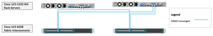
In all VersaStack designs, Cisco UCS C-series rack mount servers are always connected via the Cisco UCS FIs and managed through Cisco UCS Manager to provide a common management plane. Cisco UCS Manager 2.2 and later versions allow customers to connect Cisco UCS C-Series servers directly to Cisco UCS Fabric Interconnects without requiring a Fabric Extender (FEX). While Cisco UCS C-Series connectivity using Cisco Nexus 2232 FEX is still supported and recommended for large scale Cisco UCS C-Series server deployments, direct attached design allows customers to connect and manage Cisco UCS C-Series servers on a smaller scale without a need for buying additional hardware. In the VersaStack with ACI design, two Cisco UCS C220-M4 servers were directly attached to Cisco UCS FI using two 10Gbps converged connections (one connection to each FI) as shown in Figure 22.
Figure 22 Cisco UCS C220 Connectivity
Cisco UCS Server configuration for VSphere
The ESXi nodes consist of Cisco UCS B200-M4 series blades with Cisco 1340 VIC or Cisco UCS C220-M4 rack mount servers with Cisco 1227 VIC. These nodes are allocated to a VMware High Availability (HA) cluster to support infrastructure services and applications. At the server level, the Cisco 1227/1340 VIC presents multiple virtual PCIe devices to the ESXi node and the vSphere environment identifies these interfaces as vmnics or vmhbas. The ESXi operating system is unaware of the fact that the NICs or HBAs are virtual adapters.
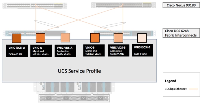
In the VersaStack design for iSCSI storage, six vNICs are created and utilized as follows (Figure 23):
· One vNIC for iSCSI-A traffic
· One vNIC for iSCSI-B traffic
· Two vNICs for infrastructure traffic including management and vMotion traffic
· Two vNICs for application related data including storage access if required. These vNICs are assigned to APIC controlled distributed switch (vDS or AVS)
These vNICs are pinned to different fabric interconnect uplink interfaces and are assigned to separate vSwitches and virtual distributed switches based on the type of traffic. The vNIC to vSwitch assignment is covered later in the document.
Figure 23 Cisco UCS –Server Interface Design for iSCSI based Storage
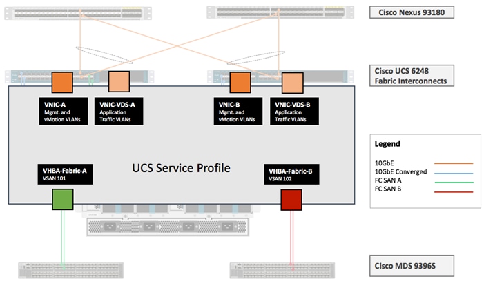
In the VersaStack design for FC storage, four vNICs and two vHBAs are created and utilized as follows (Figure 24):
· Two vNICs for infrastructure traffic including management and vMotion traffic
· Two vNICs for application related data including application storage access if required. These vNICs are assigned to APIC controlled distributed switch
· One vHBA for VSAN-A FC traffic
· One vHBA for VSAN-B FC traffic
Figure 24 Cisco UCS - Server Interface Design for FC based Storage
IBM Storage Systems
IBM SAN Volume Controller, IBM FlashSystem 900 and IBM Storwize V5030, covered in this VersaStack with ACI design, are deployed as high availability storage solutions. IBM storage systems support fully redundant connections for communication between control enclosures, external storage, and host systems.
Each storage system provides redundant controllers and redundant iSCSI and FC paths to each controller to avoid failures at path as well as hardware level. For high availability, the storage systems are attached to two separate fabrics, SAN-A and SAN-B. If a SAN fabric fault disrupts communication or I/O operations, the system recovers and reattempts the operation through the alternative communication path. Host (ESXi) systems are configured to use ALUA multi-pathing, and in case of SAN fabric fault or node failure, the host seamlessly switches over to alternate I/O path.
IBM SAN Volume Controller – I/O Groups
The SAN Volume Controller design is highly scalable and can be expanded up to eight nodes in one clustered system. An I/O group is formed by combining a redundant pair of SAN Volume Controller nodes. In this design document, two pairs of SVC nodes were deployed: a pair of IBM 2145-DH8 nodes (I/O Group 0) and a pair of IBM 2145-SV1 nodes (I/O Group 1).
![]() Based on the specific storage requirements, the number of I/O Groups in customer deployments will vary.
Based on the specific storage requirements, the number of I/O Groups in customer deployments will vary.
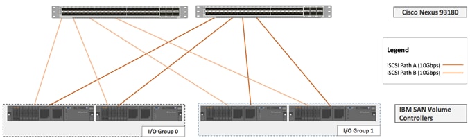
IBM SAN Volume Controller – iSCSI Connectivity
To support iSCSI based IP storage connectivity, each IBM SAN Volume Controller is connected to each of the Cisco Nexus 93180 leaf switch. The physical connectivity is shown in Figure 25. Two 10GbE ports from each IBM SAN Volume Controller are connected to each of the two Cisco Nexus 93180 leaf switches providing an aggregate bandwidth of 40Gbps. In this design, 10Gbps Ethernet ports between the SAN Volume Controllers I/O Groups and the ACI fabric utilize redundant iSCSI-A and iSCSI-B paths and can tolerate link or device failures. Additional ports can be easily added for additional bandwidth.
Figure 25 IBM SAN Volume Controller - iSCSI based Storage Access
IBM SAN Volume Controller - FC Connectivity
To support FC based storage connectivity, each IBM San Volume Controller is connected to Cisco UCS Fabric Interconnect using redundant SAN configuration provided by two Cisco MDS 9396S switches.
![]() This design guide covers both iSCSI and FC based compute to storage connectivity options to highlight flexibility of the VersaStack storage configuration. A customer can choose an iSCSI-only or an FC-only configuration design when virtualizing storage arrays behind SVC nodes.
This design guide covers both iSCSI and FC based compute to storage connectivity options to highlight flexibility of the VersaStack storage configuration. A customer can choose an iSCSI-only or an FC-only configuration design when virtualizing storage arrays behind SVC nodes.
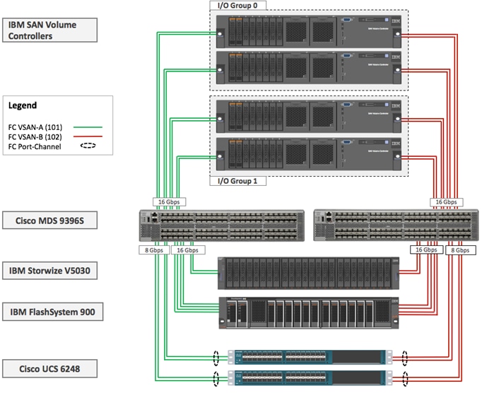
IBM SAN Volume Controller – Connectivity to the UCS, FlashSystem 900 and Storwize V5030
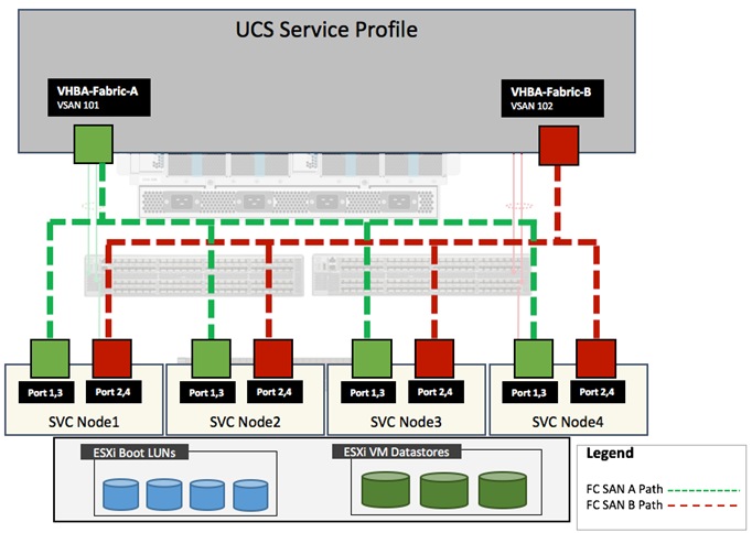
Figure 26 illustrates connectivity between SAN Volume Controllers and the FlashSystem 900 and Storwize V5030 storage arrays using Cisco MDS 9396S switches. All connectivity between the controllers and the Storage Enclosures is 16Gbps end-to-end. The connectivity from Cisco UCS to Cisco MDS is 16Gbps FC port-channel (2 x 8Gbps FC ports). Cisco MDS switches are configured with two VSANs, 101 and 102 to provide FC connectivity between the ESXi hosts, IBM SVC nodes and the storage system enclosures. Zoning configuration on Cisco MDS switches enabled required connectivity between various elements connected to the SAN fabric.
Figure 26 IBM SAN Volume Controller – Connectivity to the Storage Devices
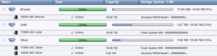
IBM SVC – Tiered Storage
The SAN Volume Controller makes it easy to configure multiple tiers of storage within the same SAN Volume Controller cluster. The system supports single-tiered storage pools, multi-tiered storage pools, or a combination of both. In a multi-tiered storage pool, MDisks with more than one type of disk tier attribute can be mixed, for example, a storage pool can contain a mix of generic_hdd and generic_ssd MDisks.
In the VersaStack with ACI and IBM SVC design, both single-tired and multi-tiered storage pools were utilized as follows:
· GOLD: All-Flash storage pool based on IBM FlashSystem 900
· SILVER: EasyTier* enabled mixed storage pool based on IBM FlashSystem 900, IBM Storwize V5030 SSDs and IBM Storwize15K Enterprise class storage
· BRONZE: SAS based storage on IBM Storwize V5030 to support less I/O intensive volumes such as the SAN Boot LUNs for ESXi Hosts etc.
* EasyTier monitors the I/O activity and latency of the extents on all volumes in a multi-tier storage pool over a 24-hour period. It then creates an extent migration plan that is based on this activity and dynamically moves high activity (or hot extents) to a higher disk tier within the storage pool. It also moves extents whose activity dropped off (or “cooled”) from the high-tier MDisks back to a lower-tiered MDisk.
Figure 27 outlines a sample configuration to show how various MDisks are created and assigned to storage pools for creating the multi-tiered storage system discussed above.
Figure 27 IBM SAN Volume Controller - Multi-tiered Storage Configuration
Network Design
In this VersaStack with Cisco ACI design, a pair of redundant Cisco Nexus 93180 leaf switches provide ACI based Ethernet switching fabric for storage and application communication including communication with the existing traditional (non-ACI) enterprise networks. Similar to previous versions of VersaStack, the core network constructs such as virtual port channels (vPC) and VLANs plays an important role in providing the necessary Ethernet based IP connectivity.
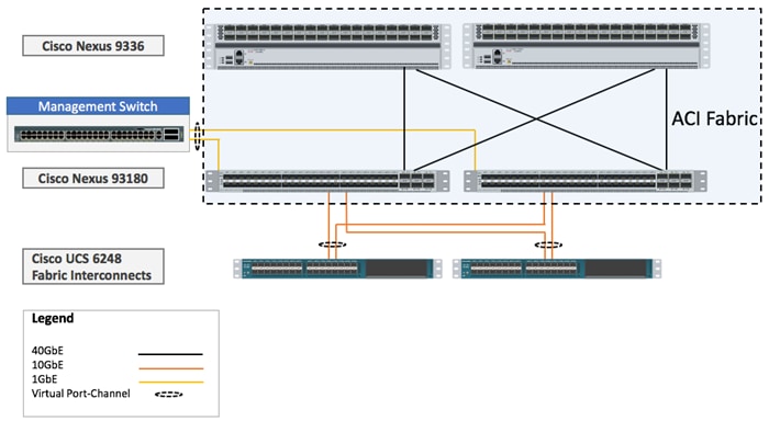
Virtual Port-Channel Design
In the current VersaStack with IBM SVC design, following devices are connected to the ACI fabric using a vPC (Figure 28):
· Cisco UCS FIs
· Connection to In-Band management infrastructure switch
Figure 28 Network Design – vPC Enabled Connections
VLAN Design
To enable connectivity between compute and storage layers of the VersaStack and to provide an in-band management access to both physical and virtual devices, several VLANs are configured and enabled on various paths. The VLANs configured for the foundation services include:
· iSCSI VLANs to provide access to iSCSI datastores including boot LUNs
· Management and vMotion VLANs used by compute and vSphere environment
· A pool of VLANs associated with ACI Virtual Machine Manager (VMM) domain. VLANs from this pool are dynamically allocated by APIC to application end point groups (covered later in the document)
These VLAN configurations are covered below.
VLANs in Cisco ACI
VLANs in an ACI do not have the same meaning as VLANs in a regular switched infrastructure. The VLAN tag for a VLAN in ACI is used purely for classification purposes. In ACI, data traffic is mapped to a bridge domain that has a global scope therefore local VLANs on two ports might differ even if they belong to the same broadcast domain. Rather than using forwarding constructs such as addressing or VLANs to apply connectivity and policy, ACI utilizes End Point Groups (EPGs) to establish communication between application endpoints. The VLAN to EPGs mapping is covered under the ACI section later in the document.
![]() In the VersaStack with ACI design, different VLANs are utilized when two or more paths are mapped to the same EPG. For example, when an ESXi host is setup for iSCSI-A connectivity, the VLAN tag used to identify this traffic on Cisco UCS FI is 3010 but the VLAN tag used on the IBM SVC is 3011. However, since the ACI fabric provides the necessary VLAN stitching, the iSCSI-A VMkernel port on ESXi host and the interface on the IBM SVC are in the same IP subnet. Figure 30 highlights the VLAN usage for the two iSCSI paths.
In the VersaStack with ACI design, different VLANs are utilized when two or more paths are mapped to the same EPG. For example, when an ESXi host is setup for iSCSI-A connectivity, the VLAN tag used to identify this traffic on Cisco UCS FI is 3010 but the VLAN tag used on the IBM SVC is 3011. However, since the ACI fabric provides the necessary VLAN stitching, the iSCSI-A VMkernel port on ESXi host and the interface on the IBM SVC are in the same IP subnet. Figure 30 highlights the VLAN usage for the two iSCSI paths.
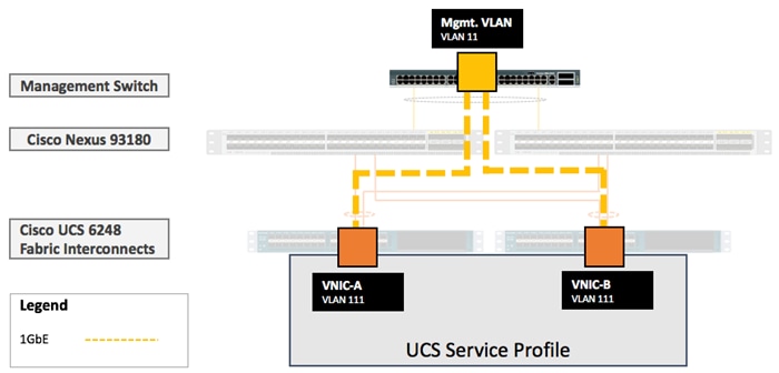
In-Band Management VLAN Configuration
To provide in-band management access to the ESXi hosts and the infrastructure/management virtual machines (VMs), the existing management infrastructure switch is connected to both the Cisco Nexus 93180 leaf switches using a vPC. In this design, VLAN 11 is the pre-existing management VLAN on the infrastructure management switch. VLAN 111 is configured as the management VLAN in Cisco UCS configuration. Within Cisco UCS service profile, VLAN 111 is enabled on vNIC-A and vNIC-B interfaces as shown in Figure 29.
Figure 29 Network Design – VLAN Mapping for in-band Management
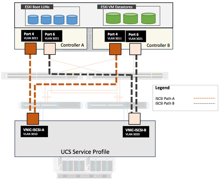
iSCSI VLAN Configuration
To provide redundant iSCSI paths, two VMkernel interfaces are configured to use dedicated NICs for host to storage connectivity. In this configuration, each VMkernel port provided a different path that the iSCSI storage stack and its storage-aware multi-pathing plugins can use.
To setup iSCSI-A path between the ESXi hosts and the IBM SVC nodes, VLAN 3010 is configured on the Cisco UCS and VLAN 3011 is configured on the IBM SVC interfaces. To setup iSCSI-B path between the ESXi hosts and the IBM SVC, VLAN 3020 is configured on the Cisco UCS and VLAN 3021 is configured on the appropriate IBM SVC node interfaces. Within Cisco UCS service profile, these VLANs are enabled on vNIC-iSCSI-A and vNIC-iSCSI-B interfaces respectively as shown in Figure 30. The iSCSI VLANs are set as native VLANs on the vNICs to enable boot from SAN functionality.
Figure 30 Network Design – VLAN mapping for iSCSI Storage Access
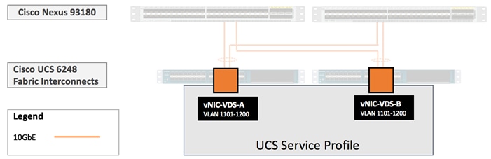
Virtual Machine Networking VLANs for VMware vDS
When using VMware vDS in an ACI setup, a pool of 100 VLANs,1101-1200, is defined to be used on-demand by the VM Networking. VLANs from this pool are dynamically assigned to the EPGs mapped to the Virtual Machine Manager (VMM) domain. Since Cisco APIC does not manage or configure the Cisco UCS FIs, the FIs are treated as unmanaged switches in the middle and the pool of VLANs needed to enable VM networking also has to be defined in Cisco UCS and enabled on the vNICs, vNIC-VDS-A and vNIC-VDS-B as shown in Figure 31.
Figure 31 Network Design – VLANs for VMM Domain Associated with VMware VDS
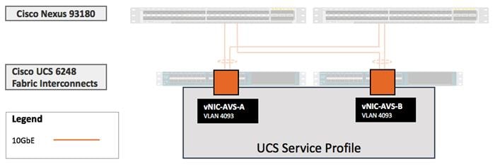
Virtual Machine Networking VLANs for Cisco AVS
When using Cisco Application Virtual Switch (AVS) VxLAN mode in an ACI setup, EPGs associated with the VMM domain utilize VxLAN and a single carrier VLAN, 4093, needs to be defined in Cisco UCS and enabled on the vNIC-AVS-A and vNIC-AVS-B interfaces as shown in Figure 32.
Figure 32 Network Design – VLANs for VMM Domain Associated with Cisco AVS
VSAN Design for Host to Storage connectivity
In the VersaStack with ACI design, isolated fabrics (A and B) are created using two Cisco MDS 9396S switches. Use of SAN zoning on Cisco MDS switches allows the isolation of traffic within specific portions of the storage area network. Cisco UCS FIs connect to the Cisco MDS switches using Port Channels while IBM SVC controllers are connected using independent FC ports. VSAN 101 and VSAN 102 provide the dual SAN paths as shown in Figure 33.
Figure 33 VSAN Design – Cisco UCS Server to IBM SVC Connectivity
Application Centric Infrastructure Design
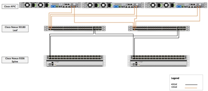
The Cisco Application Centric Infrastructure (ACI) fabric consists of discrete components that operate as routers and switches but are provisioned and monitored as a single entity. These components and the integrated management allow Cisco ACI to provide advanced traffic optimization, security, and telemetry functions for both virtual and physical workloads. This CVD utilizes Cisco ACI fabric based networking configurations as defined in the upcoming sections. Cisco ACI fabric is deployed in a leaf-spine architecture controller by a minimum of three Application Policy Infrastructure Controllers (APIC) as shown in Figure 34.
Figure 34 Cisco ACI Fabric – Physical Layout
Since the network provisioning in ACI based VersaStack is quite different from the traditional Cisco Nexus 9000 NxOS based VersaStack, the next section covers high level details of some of the core ACI components and concepts. For further details, visit www.cisco.com/go/aci.
ACI Components
Cisco APIC: The Cisco Application Policy Infrastructure Controller (APIC) is the unifying point of automation and management for the Cisco ACI fabric. The Cisco APIC provides centralized access to all fabric information, optimizes the application lifecycle for scale and performance, and supports flexible application provisioning across physical and virtual resources. The Cisco APIC exposes northbound APIs through XML and JSON and provides both a command-line interface (CLI) and GUI which utilize the APIs to manage the fabric.
Leaf switches: The ACI leaf provides physical connectivity for servers, storage devices and other network elements as well as enforces ACI policies. A leaf typically is a fixed form factor switch such as the Cisco Nexus 93180YC-EX switch used in the current design. Leaf switches also provide the connection point to the existing enterprise or service provider infrastructure. The leaf switches provide both 10G and 40G Ethernet ports for connectivity.
In the VersaStack with ACI design, Cisco UCS FI, IBM SVC and Cisco Nexus 7000 based WAN/Enterprise routers are connected to both the leaf switches for high availability.
Spine switches: The ACI spine switch provides the mapping database function and the connectivity among leaf switches. A spine switch can be the modular Cisco Nexus 9500 series equipped with ACI ready line cards or fixed form-factor switch such as the Cisco Nexus 9336PQ (used in this design). Spine switches provide high-density 40 Gigabit Ethernet connectivity between the leaf switches.
Tenant: A tenant is a logical container which can represent an actual tenant, organization, application or a construct to easily organize information. From a policy perspective, a tenant represents a unit of isolation. All application configurations in Cisco ACI are part of a tenant. Within a tenant, one or more VRF contexts, one or more bridge domains, and one or more EPGs can be defined according to application requirements.
VersaStack with ACI design requires creation of an infrastructure tenant called "Foundation" to provide compute to storage connectivity for iSCSI based SAN environment as well as to provide access to the management infrastructure. The design also utilizes the predefined "common" tenant to provide in-band management infrastructure connectivity for hosting core services required by all the tenants such as DNS, AD etc. In addition, each subsequent application deployment requires creation of a dedicated tenant.
VRF: Tenants can be further divided into Virtual Routing and Forwarding (VRF) instances (separate IP spaces) to further separate the organizational and forwarding requirements for a given tenant. Because VRFs use separate forwarding instances, IP addressing can be duplicated across VRFs for multitenancy. In the current design, each tenant typically used a single VRF.
Application Profile: An application profile models application requirements and contains one or more End Point Groups (EPGs) as necessary to provide the application capabilities. Depending on the application and connectivity requirements, VersaStack with ACI design uses multiple application profiles to define multi-tier applications as well as to establish storage connectivity.
Bridge Domain: A bridge domain represents a L2 forwarding construct within the fabric. One or more EPG can be associated with one bridge domain or subnet. In ACI, a bridge domain represents the broadcast domain and the bridge domain might not allow flooding and ARP broadcast depending on the configuration. The bridge domain has a global scope, while VLANs do not. Each endpoint group (EPG) is mapped to a bridge domain. A bridge domain can have one or more subnets associated with it and one or more bridge domains together form a tenant network
End Point Group: An End Point Group (EPG) is a collection of physical and/or virtual end points that require common services and policies. An EPG example is a set of servers or VMs on a common VLAN segment providing a common function or service. While the scope of an EPG definition is much wider, in the simplest terms an EPG can be defined on a per VLAN basis where all the servers or VMs on a common LAN segment become part of the same EPG.
In the VersaStack with ACI design, various application tiers, ESXi VMkernel ports for Management, iSCSI and vMotion, and interfaces on IBM storage devices are mapped to various EPGs. The design details are covered in the later sections.
Contracts: Contracts define inbound and outbound traffic filter, QoS rules and Layer 4 to Layer 7 redirect policies. Contracts define the way an EPG can communicate with another EPG(s) depending on the application requirements. Contracts are defined using provider-consumer relationships; one EPG provides a contract and another EPG(s) consumes that contract. Contracts utilize filters to limit the traffic between the applications to certain ports and protocols.
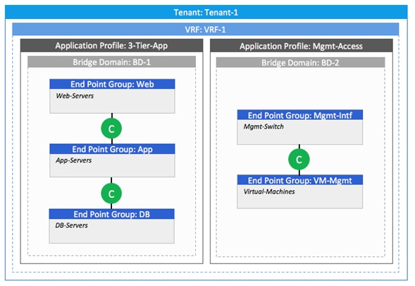
Figure 35 covers relationship between various ACI elements. As shown in the figure, a Tenant can contain one or more application profiles and an application profile can contain one or more EPGs. Devices in the same EPG can talk to each other without any special configuration. Devices in different EPGs can talk to each other using contracts and associated filters. A tenant can also contain one or more VRFs and bridge domains. Different application profiles and EPGs can utilize the same VRF or the bridge domain.
Figure 35 ACI - Relationship Between Major Components
End Point Group (EPG) Mapping in a VersaStack Environment
In the VersaStack with ACI and IBM SVC infrastructure, traffic is associated with an EPG in one of the following ways:
· Statically mapping a Path/VLAN to an EPG (Figure 36).
· Associating an EPG with a Virtual Machine Manager (VMM) domain thereby allocating a VLAN or VxLAN dynamically from a pre-defined pool in APIC (Figure 37).
Figure 36 ACI - Static Path Binding

Figure 37 ACI – EPG Assigned to Virtual Machine Manager
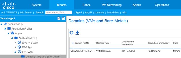
Statically mapping of Path/VLAN to an EPG is useful for:
· Mapping iSCSI VLANs on both the Cisco UCS and the IBM storage systems to appropriate EPGs
· Mapping bare metal servers to an EPG
· Mapping vMotion VLANs on the Cisco UCS/ESXi Hosts to an EPG
· Mapping the management VLAN(s) from the existing infrastructure to an EPG in the common tenant. This EPG is utilized for in-band management access by both ESXi hosts and the VMs
Dynamically mapping a VLAN to an EPG by defining a VMM domain is useful for:
· Deploying VMs in a multi-tier Application requiring one or more EPGs
· Deploying application specific IP based storage access within the application tenant environment
Virtual Machine Networking
The Cisco APIC automates the networking for all virtual and physical workloads including access policies and L4-L7 services. When connected to the VMware vCenter, APIC controls the VM related virtual distributed switching as detailed in the following sections.
Virtual Machine Manager (VMM) Domains
In a VMware vCenter environment, Cisco APIC controls the creation and configuration of the VMware vSphere Distributed Switch (VDS) or the Cisco Application Virtual Switch (AVS). Once the virtual distributed switches are deployed, APIC communicates with the switches to publish network policies that are applied to the virtual workloads including creation of port groups for VM association. A VMM domain contains multiple EPGs and hence multiple port groups. To position an application, the application administrator deploys the VMs using VMware vCenter and places the VMNIC into the port group defined for the appropriate application tier.
Virtual Switching Architecture
A tenant application deployment utilizes port groups on APIC controlled distributed switch (Cisco AVS or VDS). However, for some of the core connectivity such as out-of-band management access, vSphere vMotion and storage LUN access using iSCSI vSphere vSwitches are deployed. To support this multi-vSwitch requirement, multiple vNIC interfaces are setup in Cisco UCS services profile and storage, management and VM data VLANs are then enabled on the appropriate vNIC interfaces. Figure 38 shows the distribution of VMkernel ports and VM port-groups on an iSCSI connected ESXi server. For an ESXi server, supporting iSCSI based storage access, In-band management and vMotion traffic is handled by a Foundation Services vSwitch and iSCSI-A and iSCSI-B traffic is handled by two dedicated iSCSI vSwitches. The resulting ESXi host configuration therefore has a combination of 3 vSwitches and a single APIC-Controlled distributed switch which handles application (tenant) specific traffic.
Figure 38 ACI – ESXi Host vNIC and vmk Distribution for iSCSI based storage access
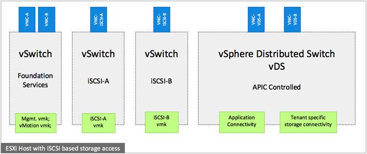
Figure 39 below shows similar configuration for an FC connected ESXi host. In this case, In-band management, and vMotion traffic is handled by a Foundation Services vSwitch but the two vSwitches for iSCSI traffic are not needed. The Fibre Channel SAN-A and SAN-B traffic is handled by two dedicated vHBAs. The resulting ESXi host configuration therefore has a combination of one vSwitch and one APIC controlled distributed switch.
Figure 39 ACI – ESXi Host vNIC, vHBA and vmk Distribution for FC based storage access
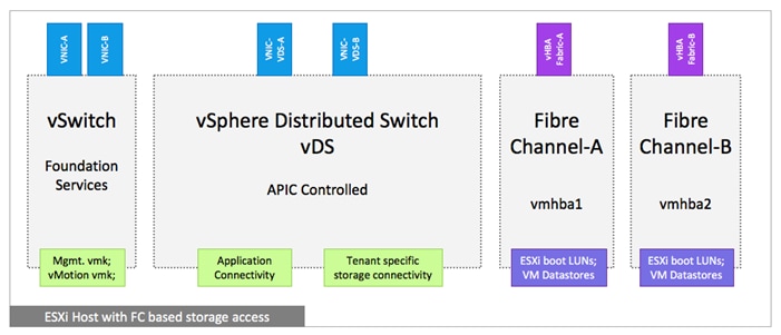
When the Cisco AVS in VxLAN mode is used instead of the VMware vDS, two VTEP vmk ports are also provisioned on the Cisco AVS as shown in Figure 40. In VxLAN mode, Cisco AVS only requires the infrastructure VLAN, 4093, to be enabled on the vNIC interfaces.
Figure 40 ACI – ESXi Host vNIC and vmk Distribution for Cisco AVS and iSCSI Based Storage
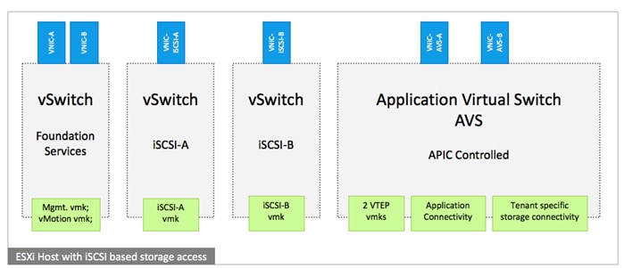
Onboarding Infrastructure Services
In an ACI fabric, all the applications, services and connectivity between various elements are defined within the confines of tenants, application profiles, bridge domains and EPGs. The tenant configured to provide the infrastructure services is named Foundation. The Foundation tenant enables compute to storage connectivity for accessing iSCSI datastores, enabled VMware vMotion traffic and provides ESXi hosts and VMs access to existing management infrastructure. The Foundation tenant comprises of a single bridge domain called bd-foundation-internal. This bridge domain is shared by all the EPGs in the Foundation tenant. Since there are no overlapping IP address space requirements, Foundation tenant consists of a single VRF called Foundation.
Foundation tenant is configured with two different Application Profiles:
· ap-ESXi-Connectivity: This application profile contains EPGs to support compute to storage connectivity as well as VMware vMotion traffic. The three EPGs defined under this application profile are: epg-iSCSI-A, epg-iSCSI-B and epg-vMotion
· ap-Mgmt: This application profile provides ESXi host and VMs connectivity to existing management segment through the Common tenant (details covered later in this section)
Foundation Tenant EPG Design for iSCSI based Storage
Figure 41 shows an overview of ACI design covering connectivity details and the relationship between various ACI elements for the iSCSI based storage access.
Figure 41 ACI – Foundation Tenant EPG Design for iSCSI Storage
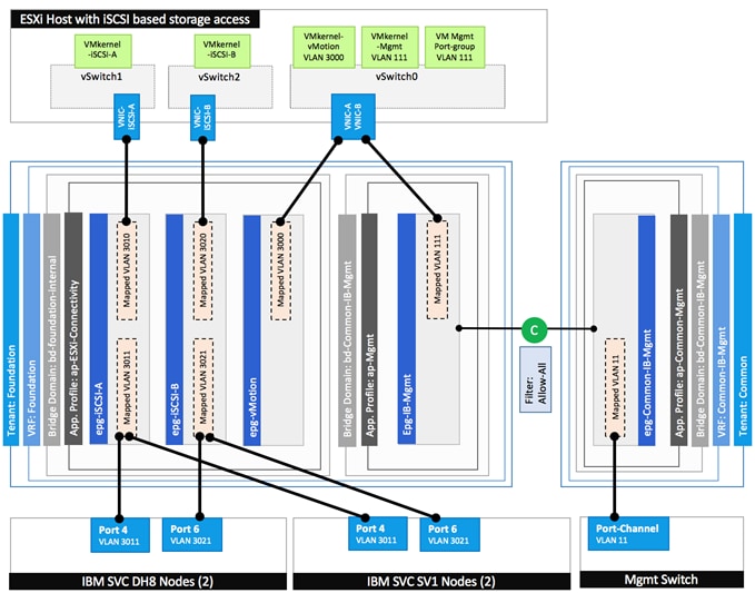
Following ACI constructs are defined the Foundation Tenant configuration for the iSCSI based storage access:
· Tenant: Foundation
· VRF: Foundation
· Bridge Domain: bd-foundation-internal
· Application Profile ap-ESXi-Connectivity consist of three EPGs:
— epg-iSCSI-A statically maps the VLANs associated with iSCSI-A interfaces on the IBM storage controllers (VLAN 3011) and Cisco UCS Fabric Interconnects (3010)
— epg-iSCSI-B statically maps the VLANs associated with iSCSI-B interfaces on the IBM storage controllers (VLAN 3021) and Cisco UCS Fabric Interconnects (3020)
— epg-vMotion statically maps vMotion VLAN (3000) on the Cisco UCS Fabric Interconnects
· Application Profile ap-Mgmt consist of one EPGs:
— epg-IB-Mgmt statically maps the management VLAN (111) on the Cisco UCS Fabric Interconnects. This EPG is configured to provide VMs and ESXi hosts access to the existing management network as covered in the next section. As shown in figure 41, this EPG utilizes the bridge domain bd-Common-IB-Mgmt from the common tenant.
Enabling Management Access through Common Tenant
To provide ESXi hosts and VMs access to management segment and common services such as Active Directory (AD), Domain Name Services (DNS), management and monitoring software etc., inter-tenant contracts are utilized. Cisco ACI fabric provides a predefined tenant named common to host the common services that can be easily shared by other tenants in the system. The policies defined in the common tenant are usable by all the tenants without any special configurations. By default, in addition to the locally defined contracts, all the tenants in ACI fabric can “consume” the contracts “provided” in the common tenant.
In the VersaStack environment, access to the management segment is provided as shown Figure 42.
Figure 42 ACI – Providing Management Access through the Common Tenant
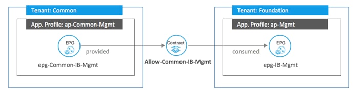
To provide this access:
· EPG epg-Common-IB-Mgmt is defined in the common tenant.
· epg-Common-IB-Mgmt statically maps the management VLAN (11) on the current management switch
· epg-Common-IB-Mgmt “provides” a contract Allow-Common-IB-Mgmt
· ESXi hosts and infrastructure related VMs become part of the EPG epg-IB-Mgmt in the Foundation tenant and access the management segment by “consuming” the Allow-Common-IB-Mgmt contract.
· Tenant VMs can also access the common management segment by “consuming” the same contract
· The contract filters can be configured to only allow specific services related ports
Onboarding Multi-Tier Application
The ACI constructs for a multi-tier application deployment include defining a new tenant, VRF(s), bridge domain(s), application profile(s), end point group(s), and the contract(s) to allow communication between various tiers of the application. Figure 44 provides an overview of the constructs required for deploying a sample two-tier application.
To deploy a sample two-tier application, following elements are configured:
· A new Tenant called App-A is defined to host the application
· A VRF called App-A is defined under the tenant to provide the tenant IP address space
· A bridge domain bd-App-A-Internal is associated with the tenant
· An application profiles, App-A is utilized to deploy the application.
· Two EPGs, App-A-Web and App-A-App are associated with the VMM domain to host Web and App/DB tiers of the application
· A contract to allow communication between the two application tiers is defined. This contract is “provided” by the EPG App-A-App and “consumed” by the EPG App-A-Web.
The VLAN or VxLAN allocation differs slightly depending on the virtual distributed switch in use. The following two sub-sections cover the deployment details for VMware vDS and Cisco AVS.
Port Group creation for VMware vDS
When application EPGs are attached to a VMware vDS based VMM domain, Cisco APIC assigns VLANs from a pre-defined pool and uses its connection to the VMware vCenter to create a new port groups on the VMware vDS. These port groups are used to deploy application VMs in the appropriate application tier. The port group name is determined using following format: “Tenant_Name | Application Profile_Name | EPG_Name”.
For example, as shown in Figure 43 below, when a new EPG App-A-Web is defined under application profile App-A (that belongs to tenant App-A), a VLAN from the dynamic VLAN pool (1137 in this example) gets assigned to this EPG and a new port group named App-A|App-A|App-A-Web is automatically created on the VMware vDS. When a virtualization administrator assigns a VM NIC to this port group, all the network policies including security (contracts), L4-L7 and QoS automatically get applied to the VM communication.
Figure 43 ACI – Attaching Application EPGs with VMware vDS
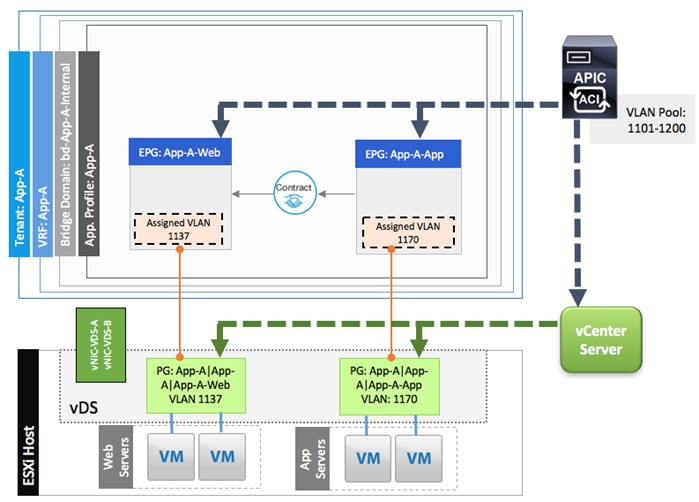
Port Group creation for Cisco AVS
When application EPGs are attached to a Cisco AVS configured for VxLAN mode, new VxLAN segments are used for creating port groups on the Cisco AVS. These port groups are then used to deploy application VMs in the appropriate application tiers.
For example, as shown in Figure 44 below, when a new EPG App-A-Web is defined under application profile App-A that belongs to tenant App-A, VxLAN 9109504 (number generated automatically) gets assigned to this EPG using the multicast address of from the pre-defined VxLAN pool (230.0.0.186 in this example). A new port-group named App-A|App-A|App-A-Web is also configured on the Cisco AVS. When an application admin attached a VM NIC to this port group, all the network policies including security (contracts), L4-L7 and QoS get applied to the VM.
Figure 44 ACI – Attaching Application EPGs with Cisco AVS
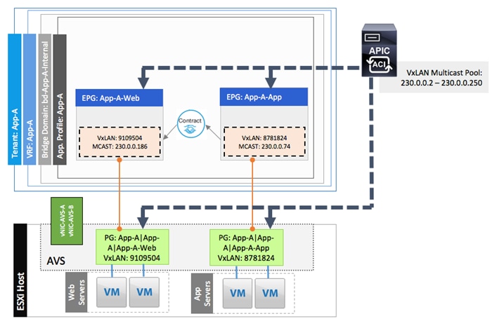
To provide layer-3 connectivity to the existing enterprise infrastructure, the application EPGs can “consume” contracts from the common tenant EPGs. Some examples of these contracts are covered in the upcoming sections.
External Network Connectivity - Shared Layer 3 Out
In order to connect ACI fabric to existing infrastructure, the ACI leaf nodes are connected to the existing enterprise core routers/switches. In this design, a Cisco Nexus 7000 was configured as the enterprise core router. Figure 45 shows the physical connectivity details. Each of the leaf switches is physically connected to each of the core router for redundancy using a 10GbE connection.
![]() In this design guide, a single pair of Cisco Nexus 9000 based leaf switches provides all the VersaStack connectivity including the layer 3 connectivity to existing infrastructure (border leaf functionality). In large scale configurations, customers are encouraged to deploy a dedicated pair of border leaf switches.
In this design guide, a single pair of Cisco Nexus 9000 based leaf switches provides all the VersaStack connectivity including the layer 3 connectivity to existing infrastructure (border leaf functionality). In large scale configurations, customers are encouraged to deploy a dedicated pair of border leaf switches.
Figure 45 ACI – Physical Connectivity to Existing Infrastructure
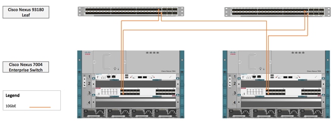
The design utilizes shared Layer 3 Out configuration, a new feature in ACI 1.2 and later, to provide routed connectivity to external networks as a shared service. Shared Layer 3 Out functionality can be deployed as a shared service in any tenant. In the VersaStack with ACI and IBM SVC validated design, this functionality in configured in the common tenant. As shown in Figure 46, a single “External Routed Network” is configured under tenant common to connect ACI infrastructure to Cisco Nexus 7000s using OSPF. Some of the ACI constructs used in this design are:
· A unique private network and a dedicated external facing bridge domain is defined under the common tenant. This private network (VRF) is setup with OSPF to provide connectivity to external infrastructure. The private network configured under the tenant common is called vrf-Common-Outside is and the bridge domain is called bd-Common-Outside.
· Four unique VLANs (sub-interfaces) are configured between ACI leaf switches and the core router; one for each of the four physical paths. The VLANs utilized are 301-304 (as seen in Figure 46).
· OSPF routing is enabled on all the four paths between the Cisco Nexus 9000 and the Cisco Nexus 7000 enterprise router
· On Cisco ACI fabric, common tenant learns a default route from the Cisco Nexus 7000 switches and advertises routable subnets to the core infrastructure.
· Cisco Nexus 7000 switches can optionally use OSPF metrics to influence path preferences.
Figure 46 ACI - Connectivity to Existing Infrastructure
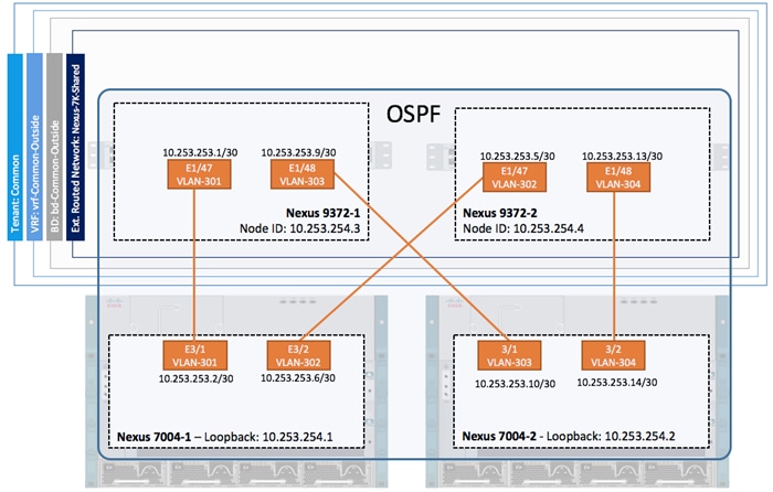
After common tenant is configured with the Layer-3 connectivity, all the other tenants can share this connection through contracts to access existing enterprise infrastructure as shown in Figure 47. The external routed network, Nexus-7K, “provides” a contract named Allow-Outside-All. When the application tenant EPGs “consume” this contract, the “public” IP subnet(s) defined under the application tenant EPGs get advertised to the enterprise network. The application EPGs also learns the default route from the tenant common. The filters under the contract control the traffic that can be sent and received from the shared L3 out. In the VersaStack with ACI and IBM SVC design, each tenant is configured with a dedicated VRF as well as a dedicated bridge domain and these constructs are not shared with other tenants.
![]() Tenant advertised prefixes for a shared Layer 3 out must to be unique; overlapping “public” subnets are not supported
Tenant advertised prefixes for a shared Layer 3 out must to be unique; overlapping “public” subnets are not supported
Figure 47 ACI – Tenant Contracts for Shared L3 Out
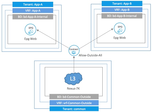
Integrating Firewall Services using Network-Only-Stitching (Unmanaged Firewall)
The network-only-stitching, or unmanaged, service graph is a relatively new option for configuring service insertion. With this option, Cisco ACI does not configure the L4-L7 device hence a device package is not needed. With network-only stitching, a L4-L7 device is configured as an unmanaged device on the Cisco APIC. However, information about the connectivity, including physical ports and VLANs, device cluster settings, and the device operation mode (routed vs transparent) needs to be defined in Cisco APIC to configure the fabric correctly.
In this VersaStack with ACI and IBM SVC design, a pair of redundant Cisco ASA5585 firewall devices are attached to Cisco Nexus 93180 leaf switches as shown in Figure 48. Each device is connected to a single Cisco Nexus 93180 leaf switch using a 2 port 10GE port-channel. The two ASA devices are configured for high availability in case of link or device failure.
Figure 48 ACI – Physical Connectivity to Cisco ASA5585 Devices
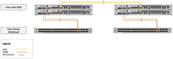
The Shared L3 connectivity section covered the L3 connection details where the traffic to and from various tenants is controlled using contract filters. To provide additional security to various application tiers, an ASA firewall (context) can be easily integrated into each tenant by using the contracts as shown in Figure 49. A contract called Allow-ASA-Traffic is provided from the application tenant EPG App-A-Web and consumed by the shared Layer 3 EPG Nexus-7K. This contract is used to redirect the web traffic to an ASA firewall context before sending the traffic out to enterprise infrastructure.
Figure 49 ACI – Adding L4-7 Services

Figure 50 shows ASA device definition under the application tenant App-A. As seen from the figure, the two ASA devices are configured as Firewall GoTo (routed) devices and are deployed as an HA cluster. VLAN 501 is configured as the provider (protected) link to the firewall and VLAN 601 is configured as the consumer (unprotected) link.
Figure 50 ACI – L4-L7 Device Definition under Application Tenant
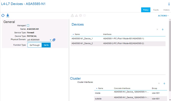
In addition to defining the L4-L7 devices, a service graph template is also configured and a service graph is deployed under the application tenant App-A. The contract provided by the EPG App-A-Web and consumed by Shared Layer 3 Out Nexus-7k results in the traffic path as shown in Figure 51.
Figure 51 ACI – ASA FW Logical Configuration

In this configuration, the VMs deployed in the EPG App-A-Web have their gateway set to inside interface of the ASA FW context (10.10.0.100) and the ASA FW’s default route is set to SVI defined in the common tenant bridge domain (192.168.249.254). The ASA is configured such that the VM traffic gets translated (NAT) to outside interface IP address of the ASA FW (192.168.249.100) before being sent out to the core router using Shared L3 Out connection.
Design Considerations
VersaStack designs incorporate connectivity and configuration best practices at every layer of the stack to provide a highly availability best performing integrated system. VersaStack is a modular architecture that allows customers to adjust the individual components of the system to meet their particular scale or performance requirements. This section covers some of the design considerations for the current design and a few additional design selection options available to the customers.
Cisco Unified Computing System I/O Component Selection
Selection of I/O components has a direct impact on scale and performance characteristics when ordering the Cisco components. Figure 52 illustrates the available backplane connections in the Cisco UCS 5100 series chassis. As shown, each of the two Fabric Extenders (I/O module) has four 10GBASE KR (802.3ap) standardized Ethernet backplane paths available for connection to the half-width blade slot. This means that each half-width slot has the potential to support up to 80Gb of aggregate traffic depending on selection of the following:
· Cisco UCS Fabric Extender model (2204XP or 2208XP)
· Modular LAN on Motherboard (mLOM) card
· Mezzanine Slot card
Figure 52 Cisco UCS B-Series M4 Server Chassis Backplane Connections
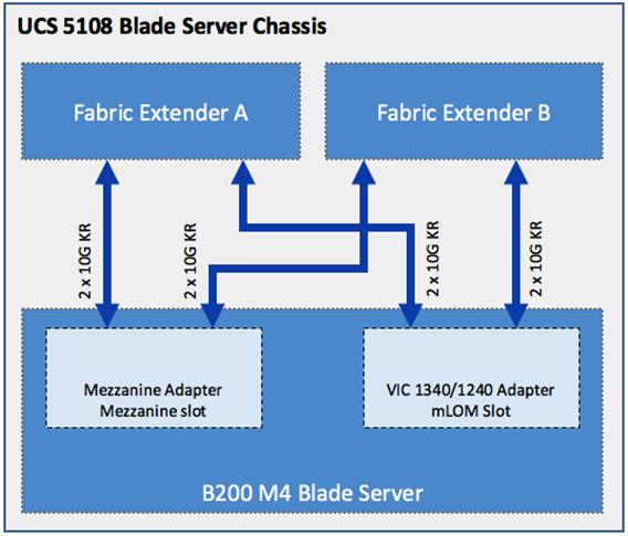
Fabric Extender Modules (FEX)
Each Cisco UCS chassis is equipped with a pair of Cisco UCS Fabric Extenders. The fabric extenders have two different models, 2208XP and 2204XP. Cisco UCS 2208XP has eight 10 Gigabit Ethernet, FCoE-capable ports that connect the blade chassis to the fabric interconnect. The Cisco UCS 2204XP has four external ports with identical characteristics to connect to the fabric interconnect. Each Cisco UCS 2208XP has thirty-two 10 Gigabit Ethernet ports connected through the mid-plane to the eight half-width slots (four per slot) in the chassis, while the 2204XP has 16 such ports (two per slot).
Table 1 Number of Network and Host Facing Interface Fabric Extenders
|
|
Network Facing Interface |
Host Facing Interface |
| Cisco UCS 2204XP |
4 |
16 |
| Cisco UCS 2208XP |
8 |
32 |
MLOM Virtual Interface Card (VIC)
The B200 M4 server accommodates different types of adapter cards. The mLOM slot only accommodates the Cisco VIC 1240 and Cisco VIC 1340 adapters, while the mezzanine slot accommodates all the other adapters (such as port expander, VIC 1280/1380, and Cisco adapters). The VersaStack with ACI solution has been validated using Cisco VIC 1340. The Cisco VIC 1340 is a two-port 40 Gigabit Ethernet FCoE-capable mLOM adapter designed for both Cisco UCS B200 M3 and M4 generation of Cisco UCS B-Series Blade Servers. When used in combination with an optional Cisco VIC 1380, the Cisco UCS VIC 1340 capabilities can be expanded to support 80Gbpst Ethernet with the use of Cisco UCS 2208XP fabric extender.
Mezzanine Slot Card
A Cisco VIC 1380 is a two-port 40 Gigabit Ethernet, FCoE-capable mezzanine adapter designed exclusively for Cisco UCS B200 M3 and m4 Blade Servers.
Validated I/O Component Configurations
The validated I/O component configurations for this VersaStack with ACI design are:
· Cisco UCS B200M3 with VIC 1240 and FEX 2208XP
· Cisco UCS B200M4 with VIC 1340 and FEX 2208XP
Cisco Unified Computing System Chassis/FEX Discovery Policy
The Cisco UCS chassis/FEX discovery policy determines how the system reacts when you add a new chassis or FEX. Cisco UCS Manager uses the settings in the chassis/FEX discovery policy to determine the minimum threshold for the number of links between the chassis or FEX and the fabric interconnect and whether to group links from the IOM to the fabric interconnect in a fabric port channel. Cisco UCS Manager cannot discover any chassis that is wired for fewer links than are configured in the chassis/FEX discovery policy.
Cisco Unified Computing System can be configured to discover a chassis using Discrete Mode or the Port-Channel mode (Figure 53). In Discrete Mode, each FEX’s KR connection and therefore server connection is tied or pinned to a network fabric connection homed to a port on the Fabric Interconnect. In case of a failure on the external "link" all KR connections are disabled within the FEX I/O module. In Port-Channel mode, the failure of a network fabric link allows for redistribution of flows across the remaining port channel members. Port-Channel mode therefore is less disruptive to the fabric and hence recommended in the VersaStack designs.
Figure 53 Cisco UCS Chassis Discovery Policy - Discrete Mode vs. Port Channel Mode
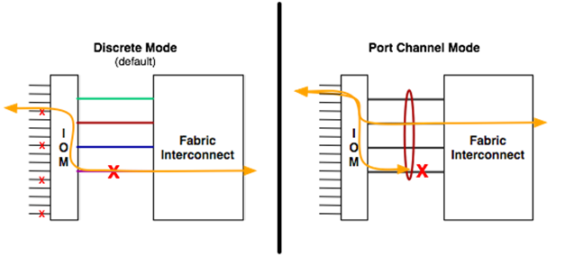
Storage Design and Scalability
SVC supports up to twenty 12Gbps serial attached SCSI (SAS) expansion enclosures per I/O group for up to 736 disk drives. These enclosures provide low-cost storage capacity to complement external virtualized storage. SVC also supports the configuration of flash drives within nodes themselves.
For a current list of supported virtualized controllers, please visit the Support Hardware Website for SVC:
FC: http://www-01.ibm.com/support/docview.wss?uid=ssg1S1005828
iSCSI: http://www-01.ibm.com/support/docview.wss?uid=ssg1S1005828
Management Network Design
This VersaStack with ACI design uses two different networks to manage the solution:
· An out-of-band management network to configure and manage physical compute, storage and network components in the solution. Management ports on each physical device (Cisco UCS FI, IBM Storage Controllers, Cisco Nexus and Cisco MDS switches) in the solution are connected to a separate, dedicated management switch.
· An in-band management network to manage and access ESXi servers and VMs (including infrastructure VMs hosted on VersaStack). Cisco UCS does allow out-of-band management of servers and VMs by using disjoint layer 2 feature but for the current design, In-band manageability is deemed sufficient.
![]() If a customer decides to utilize Disjoint L2 feature, additional uplink port(s) on the Cisco UCS FIs are required to connect to the management switches and additional vNICs have to be associated with these uplink ports. The additional vNICs are necessary since a server vNIC cannot be associated with more than one uplink.
If a customer decides to utilize Disjoint L2 feature, additional uplink port(s) on the Cisco UCS FIs are required to connect to the management switches and additional vNICs have to be associated with these uplink ports. The additional vNICs are necessary since a server vNIC cannot be associated with more than one uplink.
In certain data centers designs, there is a single management segment which requires combining both out-of-band and in-band networks into one.
Dedicated Management Cluster
The current VersaStack with ACI design assumes infrastructure VMs such as vCenter, AD, DNS etc. are all running on the dedicated management cluster. The design also supports running these VMs on the VersaStack infrastructure, instead of dedicated management cluster, but the design details are not covered in this document.
The management cluster comprises of two UCS C220 M4 servers. These two stand-alone (not managed through UCS Manager) UCS C220 M4 rack servers are configured to boot ESXi hypervisor from internal storage using FlexFlash Secure Digital cards and are connected directly to Nexus 93180YC leaf switches. The network configuration on these servers is as follows:
In-Band Management Connection
Two 1Gbps ports are connected to the existing enterprise in-band management switches. On the ESXi host, these two ports are assigned to vSwitch0. The ESXi host management VMkernel port as well as infrastructure VMs utilize this link for in-band management access. Figure 54 and 55 below cover the management connectivity details.
![]() On an ESXi host, the two 1Gbps ports should be connected to separate management switches for high availability.
On an ESXi host, the two 1Gbps ports should be connected to separate management switches for high availability.
Storage and vMotion Connectivity
To provide ESXi servers access to the shared iSCSI storage from IBM SVC, the two 10Gbps ports are connected to both the Nexus 93180 leaf switches. On the Nexus leaf switches, a Virtual Port-Channel (vPC) is configured for each of the UCS C220 M4 server. Since this deployment utilizes a vSwitch for storage connectivity, the port-channel mode is set to ON instead of LACP. These port-channels carry the storage and vMotion VLANs on the vPC. These VLANs are mapped to existing iSCSI and vMotion EPGs in the Foundation tenant to enable communication with the IBM SVC.
On the ESXi host, the two 10Gbps ports are assigned to vSwitch1 and the Load Balancing policy under NIC Teaming is set to “Route based on IP hash” to utilize both the uplinks. The two VMkernel ports used for iSCSI (A and B) and the VMkernel port used for vMotion are configured on this vSwitch1 and tagged with iSCSI-A, iSCSI-B and vMotion VLANs. Figure 55 and 56 below cover the storage connectivity details.
Figure 54 Management Cluster Physical Connectivity
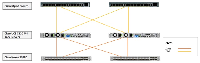
Figure 55 Management Cluster Logical Connectivity
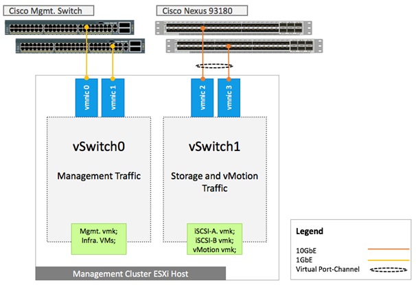
Virtual Port Channel Configuration
Virtual Port Channel (vPC) allows Ethernet links that are physically connected to two different Cisco Nexus 9000 Series devices to appear as a single Port Channel. vPC provides a loop-free topology and enables fast convergence if either one of the physical links or a device fails. Unlike an NxOS based design, a vPC configuration in ACI does not require a vPC peer-link to be explicitly connected and configured between the peer-devices (leaf switches). The peer communication is carried over the 40G connections through the spines. In the VersaStack with ACI design, when possible, vPC is a preferred mode of Port Channel configuration.
Jumbo Frame Configuration
Enabling jumbo frames in a VersaStack environment optimizes throughput between devices by enabling larger size frames on the wire while reducing the CPU resources to process these frames. VersaStack supports wide variety of traffic types (vMotion, NFS, iSCSI, control traffic, etc.) that can benefit from a larger frame size. Cisco UCS and Cisco ACI policies enable and deliver the jumbo frame functionality. In VMware vSphere, the jumbo frames are configured by setting MTU sizes at both vSwitches and VMkernel ports. On IBM storage systems, the interface MTUs are modified to enable the jumbo frame. In this validation effort, the VersaStack was configured to support jumbo frames with an MTU size of 9000.
![]() When setting the Jumbo frames, it is important to make sure MTU settings are applied uniformly across the stack to prevent fragmentation and the negative performance.
When setting the Jumbo frames, it is important to make sure MTU settings are applied uniformly across the stack to prevent fragmentation and the negative performance.
Distributed Switch – VLAN vs VxLAN encapsulation
Cisco ACI supports both VMware vDS and Cisco AVS and the VersaStack with ACI design was validated using both the switches. Both VMware vDS and Cisco AVS support VLAN encapsulation mode. In addition, Cisco AVS also supports VxLAN encapsulation mode. In this design guide, VLAN encapsulation mode for vDS and VxLAN encapsulation mode for Cisco AVS is used.
When choosing VLAN encapsulation for vDS (or AVS), a range of VLANs must be available for use by APIC. A pool of 100 VLANs is configured and assigned to VMM domain supporting vDS. These VLANs also need to be configured on the Cisco UCS FIs and assigned to the appropriate vNIC interfaces as shown in Figure 57. While Cisco APIC enables a single VLANs for every new EPG, Cisco UCS FIs act as unmanaged switches in the middle and are therefore not configured by APIC.
![]() Cisco UCS Director based ACI deployment is capable of configuring Cisco UCS FIs dynamically and pre-defining the VLAN pool on Cisco UCS is therefore not needed.
Cisco UCS Director based ACI deployment is capable of configuring Cisco UCS FIs dynamically and pre-defining the VLAN pool on Cisco UCS is therefore not needed.
Figure 56 VLAN Configuration for VMware vDS
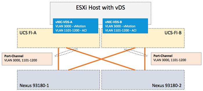
When choosing VXLAN encapsulation for AVS, only the infra-VLAN needs to be available between the Cisco AVS and the leaf switches as shown in Figure 58. This results in a simplified configuration and therefore with Cisco AVS and Cisco UCS FIs, VxLAN is the recommended encapsulation type.
Figure 57 VLAN Configuration for Cisco AVS
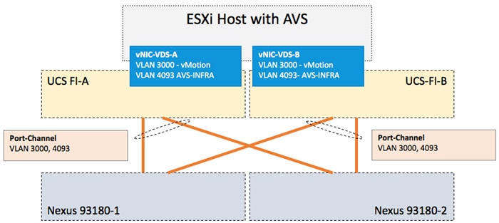
Cisco AVS – VxLAN Load Balancing
The VTEP interfaces provides necessary VxLAN encapsulation. When the host (ESXi server) is added to the AVS in VMware vCenter, the Cisco APIC creates a single VMware kernel NIC (vmknic) or VTEP. However, the specific combination of VXLAN encapsulation and MAC pinning does not provide a built-in load-balancing mechanism when there are multiple (two in this case) uplinks between Cisco AVS and the leaf switch. To enable VXLAN load balancing, a second vmknic is added to the Cisco AVS. Since each vmknic uses only one uplink port, therefore two vmknics are defined to utilize both the uplinks.
![]() Note: Currently a maximum of eight vmknics can be attached to a Cisco AVS switch. For more information, visit: http://www.cisco.com/c/en/us/td/docs/switches/datacenter/nexus1000/avs/config-guide/5-2-1-SV3-2-1/b_Cisco-AVS-Config_5-2-1-SV3-2-1/b_Cisco-AVS-Config_5-2-1-SV3-2-x_chapter_010.html#concept_8C00478124984398A345786E2A27884E
Note: Currently a maximum of eight vmknics can be attached to a Cisco AVS switch. For more information, visit: http://www.cisco.com/c/en/us/td/docs/switches/datacenter/nexus1000/avs/config-guide/5-2-1-SV3-2-1/b_Cisco-AVS-Config_5-2-1-SV3-2-1/b_Cisco-AVS-Config_5-2-1-SV3-2-x_chapter_010.html#concept_8C00478124984398A345786E2A27884E
Compute Scalability Considerations
For added scalability, additional UCS chassis can be added to any of the open ports on the ACI fabric leaf. These additional UCS domains will utilize shared network policies and will integrate seamlessly into any existing ACI network design for VM traffic as well as iSCSI based storage access (if configured). Customers can choose to manage additional UCS domains individually or deploy UCS Central to manage all the domains collectively. Figure 58 shows example of two Cisco UCS domains connected in the VersaStack design.
Figure 58 Multiple UCS Domains
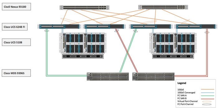
Compute and Virtualization High Availability Considerations
In the VersaStack solution, each ESXi server is deployed using vNICs and vHBAs that provide redundant connectivity to the unified fabric. All of the server NICs and HBAs are configured to use both the Cisco UCS FIs to avoid traffic disruptions.
VMware vCenter is used to deploy VMware HA clusters to allow VMs to failover in the event of a server failure. VMware vMotion and VMware HA are enabled to auto restart VMs after a failure. Host Monitoring is enabled to monitor heartbeats of all ESXi hosts in the cluster for faster detection. Admission Control is also enabled on the blade servers to ensure the cluster has enough resources to accommodate a single host failure.
VMware vSphere hosts use SAN multi-pathing to access LUNs on the IBM storage devices. If any component (NIC, HBA, FEX, FI, Cisco MDS, IBM controller, cables) along the path fails, all storage traffic will reroute to an alternate path. When both paths are active, traffic is load balanced.
Hardware and Software Revisions
Table 2 below outlines the hardware and software versions used for the solution validation. It is important to note that Cisco, IBM, and VMware have interoperability matrices that should be referenced to determine support for any specific implementation of VersaStack. Please refer to the following links for more information:
· IBM System Storage Interoperation Center
· Cisco UCS Hardware and Software Interoperability Tool
Table 2 Hardware and Software Revisions Validated
| Layer |
Device |
Image |
Comments |
| Compute |
Cisco UCS Fabric Interconnects 6200 Series, Cisco UCS B-200 M4, Cisco UCS C-220 M4 |
3.1(2b) |
Includes the Cisco UCS-IOM 2208XP, Cisco UCS Manager, and Cisco UCS VIC 1340 |
| Cisco ESXi enic |
2.3.0.10 |
Ethernet driver for Cisco VIC |
|
| Cisco ESXi fnic Driver |
1.6.0.28 |
FCoE driver for Cisco VIC |
|
| Network |
Cisco Nexus Switches |
12.0(2h) |
iNXOS |
| Cisco APIC |
2.0(2h) |
ACI release |
|
| Cisco MDS 9396S |
7.3(0)D1(1) |
FC switch firmware version |
|
| Storage |
IBM SVC |
7.7.1.3 |
Software version |
| IBM FlashSystem 900 |
1.4.5.0 |
Software version |
|
| IBM Storwize V5030 |
7.7.1.3 |
Software version |
|
| Software |
VMware vSphere ESXi |
6.0 update 2 |
Software version |
| VMware vCenter |
6.0 update 2 |
Software version |
|
| Cisco AVS |
5.2(1)SV3(2.2) |
Software version |
Test Plan
The VersaStack with ACI solution was validated for by deploying multiple VMs running IOMeter tool. The system was validated for resiliency by failing various aspects of the system under the load. The types of tests executed on the system are as follows:
Cisco UCS Validation
· Failure and recovery of links from Cisco UCS Chassis (IOM) to FI-A and FI-B, one at a time
· Failure and recovery of links from Cisco UCS C220 to FI-A and FI-B, one at a time
· Rebooting Cisco UCS FI, one at a time
· Removing the physical cables between Cisco UCS FIs and Cisco Nexus 93180 leaf switches to simulate path failure
Network and ACI Validation
· Fail/power off both Cisco 9336 spine switches, one after the other
· Fail/power off both Cisco 93180 leaf switches, one after the other
· Fail/isolate single Cisco APIC
· Fail/isolate Cisco APIC cluster
· Remove multiple links between Cisco Nexus 93180 leaf switches and Cisco Nexus 7004 switches
Storage Validation
· Failure and recovery of the Cisco MDS switches, one at a time
· Failure and recovery of the links between Cisco MDS and IBM storage controllers
· Failure and recovery of links between Cisco UCS FI and Cisco MDS
· Failure and recovery of the links between Cisco Nexus 93180 leaf switches and IBM SVC Nodes
vSphere Validation
· Failure and recovery of ESXi hosts in a cluster (rebooting of hosts, shutting down of hosts etc.)
· In case of a host failure, verify VM auto restart within the HA cluster
· VM vMotion across both B-Series and C-Series servers
· Storage vMotion between iSCSI and FC datastores (when applicable)
· Restart/Isolate vCenter server
Bill of Materials
To find various components of VersaStack system:
· Go to the Main CCW page: https://apps.cisco.com/Commerce/home
· Under Find Products and Solutions, Click on the Search for solutions
· Type VersaStack System will pull all the VersaStack variations
· Select one of the solutions and click View Components
VersaStack with ACI and IBM SVC solution is designed to simplify the data center evolution to a shared cloud-ready infrastructure by using an application driven policy model. The solution delivers an application centric architecture with centralized automation that combines software flexibility with the hardware performance. Integration of IBM SVC to the VersaStack platform standardizes storage functionality across different arrays and provides a single point of control for virtualized storage for greater flexibility.
VersaStack data center with Cisco ACI and IBM SVC architecture aligns with the converged infrastructure configurations and best practices as identified by previous VersaStack releases. The system includes hardware and software compatibility support between all components and aligns to the configuration recommendations for each of these components. VersaStack design discussed in this document has been validated for resiliency (under fair load) and fault tolerance during system upgrades, component failures, and partial as well as complete loss of power scenarios.
Products and Solutions
Cisco Unified Computing System:
http://www.cisco.com/en/US/products/ps10265/index.html
Cisco UCS 6200 Series Fabric Interconnects:
http://www.cisco.com/en/US/products/ps11544/index.html
Cisco UCS 5100 Series Blade Server Chassis:
http://www.cisco.com/en/US/products/ps10279/index.html
Cisco UCS B-Series Blade Servers:
Cisco UCS C-Series Rack Servers:
http://www.cisco.com/c/en/us/products/servers-unified-computing/ucs-c-series-rack-servers/index.html
Cisco UCS Adapters:
http://www.cisco.com/en/US/products/ps10277/prod_module_series_home.html
Cisco UCS Manager:
http://www.cisco.com/en/US/products/ps10281/index.html
Cisco Nexus 9000 Series Switches:
Cisco Application Centric Infrastructure:
VMware vCenter Server:
http://www.vmware.com/products/vcenter-server/overview.html
VMware vSphere:
https://www.vmware.com/tryvmware_tpl/vsphere-55_evalcenter.html
IBM SAN Volume Controller
http://www-03.ibm.com/systems/storage/software/virtualization/svc/
IBM FlashSystem 900:
http://www-03.ibm.com/systems/storage/flash/900/
IBM Storwize V5000:
http://www-03.ibm.com/systems/storage/disk/storwize_v5000/overview.html
Interoperability Matrixes
Cisco UCS Hardware Compatibility Matrix:
VMware and Cisco Unified Computing System:
http://www.vmware.com/resources/compatibility
IBM System Storage Interoperation Center:
http://www-03.ibm.com/systems/support/storage/ssic/interoperability.wss
IBM System Storage Interoperation Center:
http://www-03.ibm.com/systems/support/storage/ssic/interoperability.wss
Haseeb Niazi, Technical Marketing Engineer, Computing Systems Product Group, Cisco Systems, Inc.
Haseeb Niazi has over 17 years of experience at Cisco in the Data Center, Enterprise and Service Provider solutions and technologies. As a member of various solution teams and Advanced Services, Haseeb has helped many enterprise and service provider customers evaluate and deploy a wide range of Cisco solutions. As a technical marking engineer at Cisco UCS solutions group, Haseeb currently focuses on network, compute, virtualization, storage and orchestration aspects of various Compute Stacks. Haseeb holds a master's degree in Computer Engineering from the University of Southern California and is a Cisco Certified Internetwork Expert (CCIE 7848).
Adam H. Reid, Test Specialist, Systems & Technology Group, IBM
Adam H. Reid is a published author with more than 15 years of Computer Engineering experience. Focused more recently on IBM's Spectrum Virtualize, he’s been deeply involved with the testing and configuration of virtualized environments pivotal to the future of software defined storage. Adam has designed, tested and validated systems to meet the demands of a wide range of mid-range and enterprise environments.
Acknowledgements
Authors would like to thank Sreenivasa Edula, Technical Marketing Engineer, Cisco Systems, Inc. for his contributions in building this solution and his valuable input in developing this design document.
 Feedback