FlexPod Datacenter with End-to-End 100G, Cisco Intersight Managed Mode, VMware 7U3, and NetApp ONTAP 9.11
Available Languages
Bias-Free Language
The documentation set for this product strives to use bias-free language. For the purposes of this documentation set, bias-free is defined as language that does not imply discrimination based on age, disability, gender, racial identity, ethnic identity, sexual orientation, socioeconomic status, and intersectionality. Exceptions may be present in the documentation due to language that is hardcoded in the user interfaces of the product software, language used based on RFP documentation, or language that is used by a referenced third-party product. Learn more about how Cisco is using Inclusive Language.
- US/Canada 800-553-2447
- Worldwide Support Phone Numbers
- All Tools
 Feedback
 Feedback
Published: December 2022
![]()
In partnership with:

About the Cisco Validated Design Program
The Cisco Validated Design (CVD) program consists of systems and solutions designed, tested, and documented to facilitate faster, more reliable, and more predictable customer deployments. For more information, go to: http://www.cisco.com/go/designzone.
The FlexPod Datacenter solution is a validated approach for deploying Cisco and NetApp technologies and products to build shared private and public cloud infrastructure. Cisco and NetApp have partnered to deliver a series of FlexPod solutions that enable strategic data-center platforms. The success of the FlexPod solution is driven through its ability to evolve and incorporate both technology and product innovations in the areas of management, compute, storage, and networking. This document covers deployment details of incorporating the new Cisco UCS 5th Generation components into the FlexPod Datacenter and the ability to manage FlexPod components from the cloud using Cisco Intersight. Some of the key advantages of integrating Cisco UCS 5th generation components into the FlexPod infrastructure are:
● Simpler and programmable infrastructure: infrastructure as code delivered through a single partner integrable open API
● End-to-End 100Gbps Ethernet: utilizing the 5th Generation Cisco UCS VIC 15231, the 5th Generation Cisco UCS 6536 Fabric Interconnect, and the UCSX-I-9108-100G Intelligent Fabric Module to deliver 100Gbps Ethernet from the server through the network to the storage
● End-to-End 32Gbps Fibre Channel: utilizing the 5th Generation Cisco UCS VIC 15231, the 5th Generation Cisco UCS 6536 Fabric Interconnect, and the UCSX-I-9108-100G Intelligent Fabric Module to deliver 32Gbps Ethernet from the server (via 100Gbps FCoE) through the network to the storage
● Innovative cloud operations: continuous feature delivery and no need for maintaining on-premise virtual machines supporting management functions
● Built for investment protections: design ready for future technologies such as liquid cooling and high-Wattage CPUs; CXL-ready
In addition to the compute-specific hardware and software innovations, the integration of the Cisco Intersight cloud platform with VMware vCenter and NetApp Active IQ Unified Manager delivers monitoring, orchestration, and workload optimization capabilities for different layers (virtualization and storage) of the FlexPod infrastructure. The modular nature of the Cisco Intersight platform also provides an easy upgrade path to additional services, such as workload optimization.
Customers interested in understanding the FlexPod design and deployment details, including the configuration of various elements of design and associated best practices, should refer to Cisco Validated Designs for FlexPod, here: https://www.cisco.com/c/en/us/solutions/design-zone/data-center-design-guides/flexpod-design-guides.html.
This chapter contains the following:
● Audience
Powered by the Cisco Intersight cloud-operations platform, the Cisco UCS with X-Series enables the next-generation cloud-operated FlexPod infrastructure that not only simplifies data-center management but also allows the infra-structure to adapt to the unpredictable needs of modern applications as well as traditional workloads. With the Cisco Intersight platform, customers get all the benefits of SaaS delivery and the full lifecycle management of Inter-sight-connected distributed servers and integrated NetApp storage systems across data centers, remote sites, branch offices, and edge environments.
The intended audience of this document includes but is not limited to IT architects, sales engineers, field consultants, professional services, IT managers, partner engineering, and customers who want to take advantage of an infrastructure built to deliver IT efficiency and enable IT innovation.
This document provides manual configuration deployment guidance around incorporating the Cisco Intersight—managed UCS X-Series platform with end-to-end 100Gbps within FlexPod Datacenter infrastructure. The document explains both configurations and best practices for a successful deployment. This deployment guide also highlights integration of VMware vCenter and NetApp Active IQ Unified Manager to Cisco Intersight to deliver a true cloud-based integrated approach to infrastructure management.
The following design elements distinguish this version of FlexPod from previous models:
● End-to-End 100Gbps Ethernet and 32Gbps Fibre Channel in FlexPod Datacenter
● Integration of the 5th Generation Cisco UCS 6536 Fabric Interconnect into FlexPod Datacenter
● Integration of the 5th Generation Cisco UCS 15000-series VICs into FlexPod Datacenter
● Integration of the Cisco UCSX-I-9108-100G Intelligent Fabric Module into the X-Series 9508 Chassis
● Integration of the Cisco UCS C225 and C245 M6 Servers with AMD EPYC CPUs
● Addition of the Non-Volatile Memory Express over Transmission Control Protocol (NVMe-TCP) Storage Protocol with NetApp ONTAP 9.11.1
● An integrated, more complete end-to-end Infrastructure as Code (IaC) Day 0 configuration of the FlexPod Infrastructure utilizing Ansible Scripts
● VMware vSphere 7.0 Update 3
● Integration with the FlexPod XCS Integrated System in Cisco Intersight
Deployment Hardware and Software
This chapter contains the following:
The FlexPod Datacenter with Cisco UCS and Intersight meets the following general design requirements:
● Resilient design across all layers of the infrastructure with no single point of failure
● Scalable design with the flexibility to add compute capacity, storage, or network bandwidth as needed
● Modular design that can be replicated to expand and grow as the needs of the business grow
● Flexible design that can support different models of various components with ease
● Simplified design with ability to integrate and automate with external automation tools
● Cloud-enabled design which can be configured, managed, and orchestrated from the cloud using GUI or APIs
To deliver a solution which meets all these design requirements, various solution components are connected and configured as covered in the upcoming sections.
The FlexPod Datacenter solution with end-to-end 100Gbps Ethernet is built using the following hardware components:
● Cisco UCS X9508 Chassis with Cisco UCSX-I-9108-100G Intelligent Fabric Modules (IFMs) and up to eight Cisco UCS X210c M6 Compute Nodes with 3rd Generation Intel Xeon Scalable CPUs
● Fifth-generation Cisco UCS 6536 Fabric Interconnects to support 100GbE, 25GbE, and 32GFC connectivity from various components
● Cisco UCS C225 M6 and C245 M6 rack mount servers with AMD EPYC CPUs
● High-speed Cisco NX-OS-based Cisco Nexus 93360YC-FX2 switching design to support up to 100GE and 32GFC connectivity
● NetApp AFF A800/A400 end-to-end NVMe storage with 100G Ethernet and (optional) 32G Fibre Channel connectivity
● Cisco MDS 9132T* switches to support Fibre Channel storage configuration
Note: * Cisco MDS 9132T and FC connectivity is not needed when implementing IP-based connectivity design supporting iSCSI boot from SAN, NFS, and NVMe-TCP.
The software components of the solution consist of:
● Cisco Intersight SaaS platform to deploy, maintain and support the FlexPod components
● Cisco Intersight Assist Virtual Appliance to help connect NetApp ONTAP, VMware vCenter, and Cisco Nexus and MDS switches with Cisco Intersight
● NetApp Active IQ Unified Manager to monitor and manage the storage and for NetApp ONTAP integration with Cisco Intersight
● VMware vCenter to set up and manage the virtual infrastructure as well as Cisco Intersight integration
FlexPod Datacenter for IP-based Storage Access
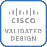
Figure 1 shows various hardware components and the network connections for the IP-based FlexPod design.
Figure 1. FlexPod Datacenter Physical Topology for IP-based Storage Access
The reference hardware configuration includes:
● Two Cisco Nexus 93360YC-FX2 Switches in Cisco NX-OS mode provide the switching fabric.
● Two Cisco UCS 6536 Fabric Interconnects (FI) provide the chassis connectivity. One 100 Gigabit Ethernet port from each FI, configured as a Port-Channel, is connected to each Cisco Nexus 93360YC-FX2.
● One Cisco UCS X9508 Chassis connects to fabric interconnects using Cisco UCSX 9108-100G Intelligent Fabric Modules (IFMs), where four 100 Gigabit Ethernet ports are used on each IFM to connect to the appropriate FI. If additional bandwidth is required, all eight 100G ports can be utilized.
● One NetApp AFF A800 HA pair connects to the Cisco Nexus 93360YC-FX2 Switches using two 100 GE ports from each controller configured as a Port-Channel.
● Two (one shown) UCS C245 rack mount servers connect to the Fabric Interconnects using two 100 GE ports per server
● Two (one shown) UCS C225 rack mount servers connect to the Fabric Interconnects via breakout using four 25 GE ports per server
FlexPod Datacenter for FC-based Storage Access
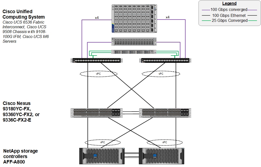
Figure 2 shows various hardware components and the network connections for the FC-based FlexPod design.
Figure 2. FlexPod Datacenter Physical Topology for FC-based Storage Access
The reference hardware configuration includes:
● Two Cisco Nexus 93360YC-FX2 Switches in Cisco NX-OS mode provide the switching fabric.
● Two Cisco UCS 6536 Fabric Interconnects (FI) provide the chassis connectivity. One 100 Gigabit Ethernet port from each FI, configured as a Port-Channel, is connected to each Cisco Nexus 93360YC-FX2. Four FC ports are connected to the Cisco MDS 9132T switches via breakout using 32-Gbps Fibre Channel connections configured as a single port channel for SAN connectivity.
● One Cisco UCS X9508 Chassis connects to fabric interconnects using Cisco UCSX 9108-100G Intelligent Fabric Modules (IFMs), where four 100 Gigabit Ethernet ports are used on each IFM to connect to the appropriate FI. If additional bandwidth is required, all eight 100G ports can be utilized.
● One NetApp AFF A800 HA pair connects to the Cisco Nexus 93360YC-FX2 Switches using two 100 GE ports from each controller configured as a Port-Channel. Two 32Gbps FC ports from each controller are connected to each Cisco MDS 9132T for SAN connectivity.
● Two (one shown) Cisco UCS C245 rack mount servers connect to the Fabric Interconnects using two 100 GE ports per server
● Two (one shown) Cisco UCS C225 rack mount servers connect to the Fabric Interconnects via breakout using four 25 GE ports per server
Note: The NetApp storage controller and disk shelves should be connected according to best practices for the specific storage controller and disk shelves. For disk shelf cabling, refer to NetApp Support: https://docs.netapp.com/us-en/ontap-systems/index.html
VLAN Configuration
Table 1 lists VLANs configured for setting up the FlexPod environment along with their usage.
| VLAN ID |
Name |
Usage |
IP Subnet used in this deployment |
| 2 |
Native-VLAN |
Use VLAN 2 as native VLAN instead of default VLAN (1). |
|
| 1020 |
OOB-MGMT-VLAN |
Out-of-band management VLAN to connect management ports for various devices |
10.102.0.0/24; GW: 10.102.0.254 |
| 1021 |
IB-MGMT-VLAN |
In-band management VLAN utilized for all in-band management connectivity - for example, ESXi hosts, VM management, and so on. |
10.102.1.0/24; GW: 10.102.1.254 |
| 1022 |
VM-Traffic |
VM data traffic VLAN |
10.102.2.0/24; GW: 10.102.2.254 |
| 3050 |
NFS-VLAN |
NFS VLAN for mounting datastores in ESXi servers for VMs |
192.168.50.0/24 ** |
| 3010* |
iSCSI-A |
iSCSI-A path for storage traffic including boot-from-san traffic |
192.168.10.0/24 ** |
| 3020* |
iSCSI-B |
iSCSI-B path for storage traffic including boot-from-san traffic |
192.168.20.0/24 ** |
| 3030 |
NVMe-TCP-A |
NVMe-TCP-A path when using NVMe-TCP |
192.168.30.0/24 ** |
| 3040 |
NVMe-TCP-B |
NVMe-TCP-B path when using NVMe-TCP |
192.168.40.0/24 ** |
| 3000 |
vMotion |
VMware vMotion traffic |
192.168.0.0/24 ** |
* iSCSI VLANs are not required if using FC storage access.
** IP gateway is not needed since no routing is required for these subnets
Some of the key highlights of VLAN usage are as follows:
● VLAN 1020 allows customers to manage and access out-of-band management interfaces of various devices.
● VLAN 1021 is used for in-band management of VMs, ESXi hosts, and other infrastructure services
● VLAN 3050 provides ESXi hosts access to the NFS datastores hosted on the NetApp Controllers for deploying VMs.
● A pair of iSCSI VLANs (3010 and 3020) is configured to provide access to boot LUNs for ESXi hosts. These VLANs are not needed if customers are using FC-only connectivity.
● A pair of NVMe-TCP VLANs (3030 and 3040) is configured to provide access to NVMe datastores when NVMe-TCP is being used
● VLAN 3000 is used for VM vMotion
Table 2 lists the infrastructure VMs necessary for deployment as outlined in this document.
| Virtual Machine Description |
VLAN |
IP Address |
Comments |
| vCenter Server |
1021 |
10.102.1.100 |
Hosted on either pre-existing management infrastructure or on FlexPod |
| NetApp ONTAP Tools |
1021 |
10.102.1.99 |
Hosted on FlexPod |
| NetApp SnapCenter for vSphere |
1021 |
10.102.1.98 |
Hosted on FlexPod |
| Active IQ Unified Manager |
1021 |
10.102.1.97 |
Hosted on FlexPod |
| Cisco Intersight Assist |
1021 |
10.102.1.96 |
Hosted on FlexPod |
Table 3 lists the software revisions for various components of the solution.
| Layer |
Device |
Image Bundle |
Comments |
| Compute |
Cisco UCS |
4.2(2c) |
Cisco UCS GA release for infrastructure including FIs and IOM/IFM. |
| Network |
Cisco Nexus 93360YC-FX2 NX-OS |
10.2(3)F |
|
| Cisco MDS 9132T |
9.2(2) |
Requires SMART Licensing |
|
| Storage |
NetApp AFF A800/A400 |
NetApp ONTAP 9.11.1P2 |
|
| Software |
Cisco UCS X210c |
5.0(2d) |
Cisco UCS X-series GA release for compute nodes |
| Cisco UCS C225/245 M6 |
4.2(2f) |
|
|
| Cisco Intersight Assist Appliance |
1.0.9-456 |
1.0.9-342 initially installed and then automatically upgraded |
|
| VMware vCenter |
7.0 Update 3h |
Build 20395099 |
|
| VMware ESXi |
7.0 Update 3d |
Build 19482537 included in Cisco Custom ISO |
|
| VMware ESXi nfnic FC Driver |
5.0.0.34 |
Supports FC-NVMe |
|
| VMware ESXi nenic Ethernet Driver |
1.0.42.0 |
|
|
| NetApp ONTAP Tools for VMware vSphere |
9.11 |
Formerly Virtual Storage Console (VSC) |
|
| NetApp NFS Plug-in for VMware VAAI |
2.0 |
|
|
| NetApp SnapCenter for vSphere |
4.7 |
Includes the vSphere plug-in for SnapCenter |
|
| NetApp Active IQ Unified Manager |
9.11P1 |
|
The information in this section is provided as a reference for cabling the physical equipment in a FlexPod environment. To simplify cabling requirements, a cabling diagram was used.
The cabling diagram in this section contains the details for the prescribed and supported configuration of the NetApp AFF 800 running NetApp ONTAP 9.11.1.
Note: For any modifications of this prescribed architecture, consult the NetApp Interoperability Matrix Tool (IMT).
Note: This document assumes that out-of-band management ports are plugged into an existing management infrastructure at the deployment site. These interfaces will be used in various configuration steps.
Note: Be sure to use the cabling directions in this section as a guide.
The NetApp storage controller and disk shelves should be connected according to best practices for the specific storage controller and disk shelves. For disk shelf cabling, refer to NetApp Support.
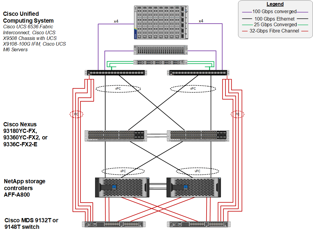
Figure 3 details the cable connections used in the validation lab for the FlexPod topology based on the Cisco UCS 6536 fabric interconnect. Four 32Gb uplinks via breakout connect as port-channels from each Cisco UCS Fabric Interconnect to the MDS switches, and a total of eight 32Gb links connect the MDS switches to the NetApp AFF controllers. Also, 100Gb links connect the Cisco UCS Fabric Interconnects to the Cisco Nexus Switches and the NetApp AFF controllers to the Cisco Nexus Switches. Additional 1Gb management connections will be needed for an out-of-band network switch that sits apart from the FlexPod infrastructure. Each Cisco UCS fabric interconnect and Cisco Nexus switch is connected to the out-of-band network switch, and each AFF controller has a connection to the out-of-band network switch. Layer 3 network connectivity is required between the Out-of-Band (OOB) and In-Band (IB) Management Subnets. This cabling diagram includes both the FC-boot and iSCSI-boot configurations.
Figure 3. FlexPod Cabling with Cisco UCS 6536 Fabric Interconnect
This chapter contains the following:
● Cisco Nexus Switch Manual Configuration
This chapter provides a detailed procedure for configuring the Cisco Nexus 93360YC-FX2 switches for use in a FlexPod environment. The Cisco Nexus 93360YC-FX2 will be used for LAN switching in this solution.
Note: The following procedures describe how to configure the Cisco Nexus switches for use in a base FlexPod environment. This procedure assumes the use of Cisco Nexus 9000 10.2(3)F.
● If using the Cisco Nexus 93360YC-FX2 switches for both LAN and SAN switching, please refer to section FlexPod with Cisco Nexus 93360YC-FX2 SAN Switching Configuration in the Appendix.
● The following procedure includes the setup of NTP distribution on both the mgmt0 port and the in-band management VLAN. The interface-vlan feature and ntp commands are used to set this up. This procedure also assumes that the default VRF is used to route the in-band management VLAN.
● This procedure sets up and uplink virtual port channel (vPC) with the IB-MGMT and OOB-MGMT VLANs allowed.
● This validation assumes that both switches have been reset to factory defaults by using the “write erase” command followed by the “reload” command.
Follow the physical connectivity guidelines for FlexPod explained in section FlexPod Cabling.
The following procedures describe this basic configuration of the Cisco Nexus switches for use in the FlexPod environment. This procedure assumes the use of Cisco Nexus 9000 10.2(3)F, the Cisco suggested Cisco Nexus switch release at the time of this validation.
Procedure 1. Set Up Initial Configuration for Cisco Nexus A Switch <nexus-A-hostname> from Serial Console
Step 1. Configure the switch.
Note: On initial boot, the NX-OS setup should automatically start and attempt to enter Power on Auto Provisioning.
Abort Power On Auto Provisioning [yes - continue with normal setup, skip - bypass password and basic configuration, no - continue with Power On Auto Provisioning] (yes/skip/no)[no]: yes
Disabling POAP.......Disabling POAP
poap: Rolling back, please wait... (This may take 5-15 minutes)
---- System Admin Account Setup ----
Do you want to enforce secure password standard (yes/no) [y]: Enter
Enter the password for "admin": <password>
Confirm the password for "admin": <password>
Would you like to enter the basic configuration dialog (yes/no): yes
Create another login account (yes/no) [n]: Enter
Configure read-only SNMP community string (yes/no) [n]: Enter
Configure read-write SNMP community string (yes/no) [n]: Enter
Enter the switch name: <nexus-A-hostname>
Continue with Out-of-band (mgmt0) management configuration? (yes/no) [y]: Enter
Mgmt0 IPv4 address: <nexus-A-out_of_band_mgmt0-ip>
Mgmt0 IPv4 netmask: <nexus-A-mgmt0-netmask>
Configure the default gateway? (yes/no) [y]: Enter
IPv4 address of the default gateway: <nexus-A-mgmt0-gw>
Configure advanced IP options? (yes/no) [n]: Enter
Enable the telnet service? (yes/no) [n]: Enter
Enable the ssh service? (yes/no) [y]: Enter
Type of ssh key you would like to generate (dsa/rsa) [rsa]: Enter
Number of rsa key bits <1024-2048> [1024]: Enter
Configure the ntp server? (yes/no) [n]: Enter
Configure default interface layer (L3/L2) [L2]: Enter
Configure default switchport interface state (shut/noshut) [noshut]: shut
Enter basic FC configurations (yes/no) [n]: n
Configure CoPP system profile (strict/moderate/lenient/dense) [strict]: Enter
Would you like to edit the configuration? (yes/no) [n]: Enter
Step 1. Review the configuration summary before enabling the configuration.
Use this configuration and save it? (yes/no) [y]: Enter
Step 2. To set up the initial configuration of the Cisco Nexus B switch, repeat steps 1 and 2 with the appropriate host and IP address information.
Cisco Nexus Switch Manual Configuration
Procedure 1. Enable Cisco Nexus Features on Cisco Nexus A and Cisco Nexus B
Step 1. Log in as admin using ssh.
Step 2. Run the following commands:
config t
feature nxapi
feature udld
feature interface-vlan
feature lacp
feature vpc
feature lldp
Procedure 2. Set Global Configurations on Cisco Nexus A and Cisco Nexus B
Note: To set global configurations, follow this step on both switches.
Step 1. Run the following commands to set global configurations:
spanning-tree port type network default
spanning-tree port type edge bpduguard default
spanning-tree port type edge bpdufilter default
port-channel load-balance src-dst l4port
ip name-server <dns-server-1> <dns-server-2>
ip domain-name <dns-domain-name>
ip domain-lookup
ntp server <global-ntp-server-ip> use-vrf management
ntp master 3
clock timezone <timezone> <hour-offset> <minute-offset>
(For Example: clock timezone EST -5 0)
clock summer-time <timezone> <start-week> <start-day> <start-month> <start-time> <end-week> <end-day> <end-month> <end-time> <offset-minutes>
(For Example: clock summer-time EDT 2 Sunday March 02:00 1 Sunday November 02:00 60)
copy run start
ip route 0.0.0.0/0 <ib-mgmt-vlan-gateway>
Note: For more information on configuring the timezone and daylight savings time or summer time, see Cisco Nexus 9000 Series NX-OS Fundamentals Configuration Guide, Release 10.2(x).
Procedure 3. Create VLANs on Cisco Nexus A and Cisco Nexus B
Note: To create the necessary virtual local area networks (VLANs), follow this step on both switches:
Step 1. From the global configuration mode, run the following commands:
vlan <oob-mgmt-vlan-id for example, 1020>
name oob-mgmt
vlan <ib-mgmt-vlan-id for example, 1021>
name ib-mgmt
vlan <native-vlan-id for example, 2>
name native-vlan
vlan <vmotion-vlan-id for example, 3000>
name vmotion
vlan <vm-traffic-vlan-id for example, 1022>
name vm-traffic
vlan <infra-nfs-vlan-id for example, 3050>
name infra-nfs
Step 2. If configuring iSCSI storage access, create the following two additional VLANs:
vlan <iscsi-a-vlan-id for example, 3010>
name infra-iscsi-a
vlan <iscsi-b-vlan-id for example, 3020>
name infra-iscsi-b
Step 3. If configuring NVMe-TCP storage access, create the following two additional VLANs:
vlan <nvme-tcp-a-vlan-id for example, 3030>
name infra-nvme-tcp-a
vlan <nvme-tcp-b-vlan-id for example, 3040>
name infra-nvme-tcp-b
Procedure 4. Add NTP Distribution Interface in IB-MGMT Subnet on
Cisco Nexus A
Step 1. From the global configuration mode, run the following commands:
interface Vlan<ib-mgmt-vlan-id>
ip address <switch-a-ntp-ip>/<ib-mgmt-vlan-netmask-length>
no shutdown
exit
ntp peer <nexus-B-mgmt0-ip> use-vrf management
Cisco Nexus B
Step 1. From the global configuration mode, run the following commands:
interface Vlan<ib-mgmt-vlan-id>
ip address <switch-b-ntp-ip>/<ib-mgmt-vlan-netmask-length>
no shutdown
exit
ntp peer <nexus-A-mgmt0-ip> use-vrf management
Procedure 5. Create Port Channels
Cisco Nexus A
Note: For fibre optic connections to Cisco UCS systems (AOC or SFP-based), entering udld enable will result in a message stating that this command is not applicable to fiber ports. This message is expected. This command will enable UDLD on twinnax connections.
Step 1. From the global configuration mode, run the following commands:
interface Po10
description vPC peer-link
!
interface Eth1/101
description <nexus-b-hostname>:Eth1/101
!
interface Eth1/102
description <nexus-b-hostname>:Eth1/102
!
interface Eth1/101-102
channel-group 10 mode active
no shutdown
!
! UCS Connectivity
!
interface Po197
description <ucs-domainname>-a
!
interface Eth1/97
udld enable
description <ucs-domainname>-a:Eth1/31
channel-group 197 mode active
no shutdown
!
interface Po198
description <ucs-domainname>-b
!
interface Eth1/98
udld enable
description <ucs-domainname>-b:Eth1/31
channel-group 198 mode active
no shutdown
!
! Storage Connectivity
!
interface Po199
description <st-clustername>-01
!
interface Eth1/99
description <st-clustername>-01:e5a
channel-group 199 mode active
no shutdown
!
interface Po1100
description <st-clustername>-02
!
interface Eth1/100
description <st-clustername>-02:e5a
channel-group 1100 mode active
no shutdown
!
! Uplink Switch Connectivity
!
interface Po102
description MGMT-Uplink
!
interface Eth1/47
description <mgmt-uplink-switch-a-hostname>:<port>
channel-group 102 mode active
no shutdown
!
interface Eth1/48
description <mgmt-uplink-switch-b-hostname>:<port>
channel-group 102 mode active
no shutdown
exit
copy run start
Cisco Nexus B
Note: For fibre optic connections to Cisco UCS systems (AOC or SFP-based), entering udld enable will result in a message stating that this command is not applicable to fiber ports. This message is expected. This command will enable UDLD on twinnax connections.
Step 1. From the global configuration mode, run the following commands:
interface Po10
description vPC peer-link
!
interface Eth1/101
description <nexus-a-hostname>:Eth1/101
!
interface Eth1/102
description <nexus-a-hostname>:Eth1/102
!
interface Eth1/101-102
channel-group 10 mode active
no shutdown
!
! UCS Connectivity
!
interface Po197
description <ucs-domainname>-a
!
interface Eth1/97
udld enable
description <ucs-domainname>-a:Eth1/32
channel-group 197 mode active
no shutdown
!
interface Po198
description <ucs-domainname>-b
!
interface Eth1/98
udld enable
description <ucs-domainname>-b:Eth1/32
channel-group 198 mode active
no shutdown
!
! Storage Connectivity
!
interface Po199
description <st-clustername>-01
!
interface Eth1/99
description <st-clustername>-01:e5b
channel-group 199 mode active
no shutdown
!
interface Po1100
description <st-clustername>-02
!
interface Eth1/100
description <st-clustername>-02:e5b
channel-group 1100 mode active
no shutdown
!
! Uplink Switch Connectivity
!
interface Po102
description MGMT-Uplink
!
interface Eth1/47
description <mgmt-uplink-switch-a-hostname>:<port>
channel-group 102 mode active
no shutdown
!
interface Eth1/48
description <mgmt-uplink-switch-b-hostname>:<port>
channel-group 102 mode active
no shutdown
exit
copy run start
Procedure 6. Configure Port Channel Parameters on Cisco Nexus A and Cisco Nexus B
Note: iSCSI and NVMe-TCP VLANs in these steps are only configured when setting up storage access for these protocols. It is assumed in this design that if you are using NVMe-TCP on a server, that you are also using iSCSI Boot on that server.
Step 1. From the global configuration mode, run the following commands to setup VPC Peer-Link port-channel:
interface Po10
switchport mode trunk
switchport trunk native vlan <native-vlan-id>
switchport trunk allowed vlan <oob-mgmt-vlan-id>,<ib-mgmt-vlan-id>,<infra-nfs-vlan-id>,<vmotion-vlan-id>, <vm-traffic-vlan-id>,<iscsi-a-vlan-id>,<iscsi-b-vlan-id>,<nvme-tcp-a-vlan-id>,<nvme-tcp-b-vlan-id>
spanning-tree port type network
Step 2. From the global configuration mode, run the following commands to setup port-channels for UCS FI 6454 connectivity:
interface Po197
switchport mode trunk
switchport trunk native vlan <native-vlan-id>
switchport trunk allowed vlan <oob-mgmt-vlan-id>,<ib-mgmt-vlan-id>,<infra-nfs-vlan-id>,<vmotion-vlan-id>, <vm-traffic-vlan-id>,<iscsi-a-vlan-id>,<iscsi-b-vlan-id>,<nvme-tcp-a-vlan-id>,<nvme-tcp-b-vlan-id>
spanning-tree port type edge trunk
mtu 9216
!
interface Po198
switchport mode trunk
switchport trunk native vlan <native-vlan-id>
switchport trunk allowed vlan <oob-mgmt-vlan-id>,<ib-mgmt-vlan-id>,<infra-nfs-vlan-id>,<vmotion-vlan-id>, <vm-traffic-vlan-id>,<iscsi-a-vlan-id>,<iscsi-b-vlan-id>,<nvme-tcp-a-vlan-id>,<nvme-tcp-b-vlan-id>
spanning-tree port type edge trunk
mtu 9216
Step 3. From the global configuration mode, run the following commands to setup port-channels for NetApp A400 connectivity:
interface Po199
switchport mode trunk
switchport trunk native vlan <native-vlan-id>
switchport trunk allowed vlan <ib-mgmt-vlan-id>,<infra-nfs-vlan-id>,<iscsi-a-vlan-id>,<iscsi-b-vlan-id>,
<nvme-tcp-a-vlan-id>,<nvme-tcp-b-vlan-id>
spanning-tree port type edge trunk
mtu 9216
!
interface Po1100
switchport mode trunk
switchport trunk native vlan <native-vlan-id>
switchport trunk allowed vlan <ib-mgmt-vlan-id>,<infra-nfs-vlan-id>,<iscsi-a-vlan-id>,<iscsi-b-vlan-id>,
<nvme-tcp-a-vlan-id>,<nvme-tcp-b-vlan-id>
spanning-tree port type edge trunk
mtu 9216
Step 4. From the global configuration mode, run the following commands to setup port-channels for connectivity to existing management switch(es):
interface Po102
switchport mode trunk
switchport trunk native vlan <native-vlan-id>
switchport trunk allowed vlan <oob-mgmt-vlan-id>,<ib-mgmt-vlan-id>,<vm-traffic-vlan-id>
spanning-tree port type network
mtu 9216
!
exit
copy run start
Procedure 7. Configure Virtual Port Channels
Cisco Nexus A
Step 1. From the global configuration mode, run the following commands:
vpc domain <nexus-vpc-domain-id for example, 10>
role priority 10
peer-keepalive destination <nexus-B-mgmt0-ip> source <nexus-A-mgmt0-ip>
peer-switch
peer-gateway
auto-recovery
delay restore 150
ip arp synchronize
!
interface Po10
vpc peer-link
!
interface Po197
vpc 197
!
interface Po198
vpc 198
!
interface Po199
vpc 199
!
interface Po1100
vpc 1100
!
interface Po102
vpc 102
!
exit
copy run start
Cisco Nexus B
Step 1. From the global configuration mode, run the following commands:
vpc domain <nexus-vpc-domain-id for example, 10>
role priority 20
peer-keepalive destination <nexus-A-mgmt0-ip> source <nexus-B-mgmt0-ip>
peer-switch
peer-gateway
auto-recovery
delay restore 150
ip arp synchronize
!
interface Po10
vpc peer-link
!
interface Po197
vpc 197
!
interface Po198
vpc 198
!
interface Po199
vpc 199
!
interface Po1100
vpc 1100
!
interface Po102
vpc 102
!
exit
copy run start
NetApp ONTAP Storage Configuration
This chapter contains the following:
● NetApp AFF A400/A800 Controllers
NetApp AFF A400/A800 Controllers
See section NetApp Hardware Universe for planning the physical location of the storage systems:
● Site Preparation
● System Connectivity Requirements
● Circuit Breaker, Power Outlet Balancing, System Cabinet Power Cord Plugs, and Console Pinout Requirements
● AFF Series Systems
To confirm that the hardware and software components that you would like to use are supported with the version of NetApp ONTAP that you plan to install, follow the steps at the NetApp Support site.
Procedure 1. Confirm hardware and software components
Step 1. Access the HWU application to view the System Configuration guides. Click the Platforms menu to view the compatibility between different versions of the NetApp ONTAP software and the NetApp storage appliances with your desired specifications.
Step 2. Alternatively, to compare components by storage appliance, click Compare Storage Systems.
Follow the physical installation procedures for the controllers here: https://docs.netapp.com/us-en/ontap-systems/index.html.
NetApp storage systems support a wide variety of disk shelves and disk drives. The complete list of disk shelves that are supported by the AFF A400 and AFF A800 is available at the NetApp Support site.
When using SAS disk shelves with NetApp storage controllers, refer to: https://docs.netapp.com/us-en/ontap-systems/sas3/index.html for proper cabling guidelines.
When using NVMe drive shelves with NetApp storage controllers, refer to: https://docs.netapp.com/us-en/ontap-systems/ns224/index.html for installation and servicing guidelines.
Complete Configuration Worksheet
Before running the setup script, complete the Cluster setup worksheet in the NetApp ONTAP 9 Documentation Center. You must have access to the NetApp Support site to open the cluster setup worksheet.
Before running the setup script, review the configuration worksheets in the Software setup section of the NetApp ONTAP 9 Documentation Center to learn about configuring NetApp ONTAP. Table 4 lists the information needed to configure two NetApp ONTAP nodes. Customize the cluster-detail values with the information applicable to your deployment.
Table 4. NetApp ONTAP Software Installation Prerequisites
| Cluster Detail |
Cluster Detail Value |
| Cluster node 01 IP address |
<node01-mgmt-ip> |
| Cluster node 01 netmask |
<node01-mgmt-mask> |
| Cluster node 01 gateway |
<node01-mgmt-gateway> |
| Cluster node 02 IP address |
<node02-mgmt-ip> |
| Cluster node 02 netmask |
<node02-mgmt-mask> |
| Cluster node 02 gateway |
<node02-mgmt-gateway> |
| ONTAP 9.11.1P2 URL (http server hosting NetApp ONTAP software) |
<url-boot-software> |
Procedure 1. Configure Node 01
Step 1. Connect to the storage system console port. You should see a Loader-A prompt. However, if the storage system is in a reboot loop, press Ctrl-C to exit the autoboot loop when the following message displays:
Starting AUTOBOOT press Ctrl-C to abort…
Step 2. Allow the system to boot up.
autoboot
Step 3. Press Ctrl-C when prompted.
Note: If NetApp ONTAP 9.11.1P2 is not the version of the software being booted, continue with the following steps to install new software. If NetApp ONTAP 9.11.1P2 is the version being booted, select option 8 and y to reboot the node, then continue with section Set Up Node.
Step 4. To install new software, select option 7 from the menu.
Step 5. Enter y to continue the installation.
Step 6. Select e0M for the network port for the download.
Step 7. Enter n to skip the reboot.
Step 8. Select option 7 from the menu: Install new software first
Step 9. Enter y to continue the installation.
Step 10. Enter the IP address, netmask, and default gateway for e0M.
Enter the IP address for port e0M: <node01-mgmt-ip>
Enter the netmask for port e0M: <node01-mgmt-mask>
Enter the IP address of the default gateway: <node01-mgmt-gateway>
Step 11. Enter the URL where the software can be found.
Note: The e0M interface should be connected to the management network and the web server must be reachable (using ping) from node 01.
<url-boot-software>
Step 12. Press Enter for the user name, indicating no user name.
Step 13. Enter y to set the newly installed software as the default to be used for subsequent reboots.
Step 14. Enter y to reboot the node.
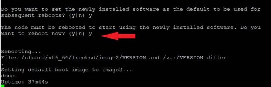
Note: When installing new software, the system might perform firmware upgrades to the BIOS and adapter cards, causing reboots and possible stops at the Loader-A prompt. If these actions occur, the system might deviate from this procedure.
Note: During the NetApp ONTAP installation a prompt to reboot the node requests a Y/N response.
Step 15. Press Ctrl-C when the following message displays:
Press Ctrl-C for Boot Menu
Step 16. Select option 4 for Clean Configuration and Initialize All Disks.
Step 17. Enter y to zero disks, reset config, and install a new file system.
Step 18. Enter yes to erase all the data on the disks.
Note: The initialization and creation of the root aggregate can take 90 minutes or more to complete, depending on the number and type of disks attached. When initialization is complete, the storage system reboots. Note that SSDs take considerably less time to initialize. You can continue with the configuration of node 02 while the disks for node 01 are zeroing.
Procedure 2. Configure Node 02
Step 1. Connect to the storage system console port. You should see a Loader-B prompt. However, if the storage system is in a reboot loop, press Ctrl-C to exit the autoboot loop when the following message displays:
Starting AUTOBOOT press Ctrl-C to abort…
Step 2. Allow the system to boot up.
autoboot
Step 3. Press Ctrl-C when prompted.
Note: If NetApp ONTAP 9.11.1P2 is not the version of the software being booted, continue with the following steps to install new software. If NetApp ONTAP 9.11.1P2 is the version being booted, select option 8 and y to reboot the node. Then continue with section Set Up Node.
Step 4. To install new software, select option 7.
Step 5. Enter y to continue the installation.
Step 6. Select e0M for the network port you want to use for the download.
Step 7. Enter n to skip the reboot.
Step 8. Select option 7: Install new software first
Step 9. Enter y to continue the installation.
Step 10. Enter the IP address, netmask, and default gateway for e0M.
Enter the IP address for port e0M: <node02-mgmt-ip>
Enter the netmask for port e0M: <node02-mgmt-mask>
Enter the IP address of the default gateway: <node02-mgmt-gateway>
Step 11. Enter the URL where the software can be found.
Note: The web server must be reachable (ping) from node 02.
<url-boot-software>
Step 12. Press Enter for the username, indicating no user name.
Step 13. Enter y to set the newly installed software as the default to be used for subsequent reboots.
Step 14. Enter y to reboot the node now.
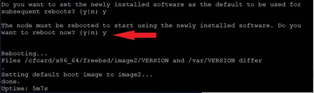
Note: When installing new software, the system might perform firmware upgrades to the BIOS and adapter cards, causing reboots and possible stops at the Loader-B prompt. If these actions occur, the system might deviate from this procedure.
Note: During the NetApp ONTAP installation a prompt to reboot the node requests a Y/N response.
Step 15. Press Ctrl-C when you see this message:
Press Ctrl-C for Boot Menu
Step 16. Select option 4 for Clean Configuration and Initialize All Disks.
Step 17. Enter y to zero disks, reset config, and install a new file system.
Step 18. Enter yes to erase all the data on the disks.
Note: The initialization and creation of the root aggregate can take 90 minutes or more to complete, depending on the number and type of disks attached. When initialization is complete, the storage system reboots. Note that SSDs take considerably less time to initialize.
Step 1. From a console port program attached to the storage controller A (node 01) console port, run the node setup script. This script appears when NetApp ONTAP 9.11.1P2 boots on the node for the first time.
Step 2. Follow the prompts to set up node 01.
Welcome to the cluster setup wizard.
You can enter the following commands at any time:
"help" or "?" - if you want to have a question clarified,
"back" - if you want to change previously answered questions, and
"exit" or "quit" - if you want to quit the setup wizard.
Any changes you made before quitting will be saved.
You can return to cluster setup at any time by typing “cluster setup”.
To accept a default or omit a question, do not enter a value.
This system will send event messages and weekly reports to NetApp Technical Support.
To disable this feature, enter "autosupport modify -support disable" within 24 hours.
Enabling AutoSupport can significantly speed problem determination and resolution should a problem occur on your system.
For further information on AutoSupport, see:
http://support.netapp.com/autosupport/
Type yes to confirm and continue {yes}: yes
Enter the node management interface port [e0M]: Enter
Enter the node management interface IP address: <node01-mgmt-ip>
Enter the node management interface netmask: <node01-mgmt-mask>
Enter the node management interface default gateway: <node01-mgmt-gateway>
A node management interface on port e0M with IP address <node01-mgmt-ip> has been created.
Use your web browser to complete cluster setup by accesing https://<node01-mgmt-ip>
Otherwise press Enter to complete cluster setup using the command line interface:
Step 3. To complete cluster setup, open a web browser and navigate to https://<node01-mgmt-ip>.
Table 5. Cluster Create in NetApp ONTAP Prerequisites
| Cluster Detail |
Cluster Detail Value |
| Cluster name |
<clustername> |
| Cluster Admin SVM |
<cluster-adm-svm> |
| Infrastructure Data SVM |
<infra-data-svm> |
| NetApp ONTAP base license |
<cluster-base-license-key> |
| Cluster management IP address |
<clustermgmt-ip> |
| Cluster management netmask |
<clustermgmt-mask> |
| Cluster management gateway |
<clustermgmt-gateway> |
| Cluster node 01 IP address |
<node01-mgmt-ip> |
| Cluster node 01 netmask |
<node01-mgmt-mask> |
| Cluster node 01 gateway |
<node01-mgmt-gateway> |
| Cluster node 02 IP address |
<node02-mgmt-ip> |
| Cluster node 02 netmask |
<node02-mgmt-mask> |
| Cluster node 02 gateway |
<node02-mgmt-gateway> |
| Node 01 service processor IP address |
<node01-sp-ip> |
| Node 01 service processor network mask |
<node01-sp-mask> |
| Node 01 service processor gateway |
<node01-sp-gateway> |
| Node 02 service processor IP address |
<node02-sp-ip> |
| Node 02 service processor network mask |
<node02-sp-mask> |
| Node 02 service processor gateway |
<node02-sp-gateway> |
| Node 01 node name |
<st-node01> |
| Node 02 node name |
<st-node02> |
| DNS domain name |
<dns-domain-name> |
| DNS server IP address |
<dns-ip> |
| NTP server A IP address |
<switch-a-ntp-ip> |
| NTP server B IP address |
<switch-b-ntp-ip> |
| SNMPv3 User |
<snmp-v3-usr> |
| SNMPv3 Authentication Protocol |
<snmp-v3-auth-proto> |
| SNMPv3 Privacy Protocol |
<snmpv3-priv-proto> |
Note: The cluster setup can also be performed using the CLI. This document describes the cluster setup using the NetApp ONTAP System Manager guided setup.
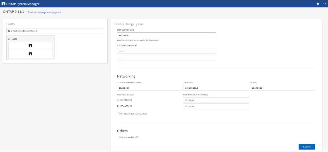
Step 4. Complete the required information on the Initialize Storage System screen:
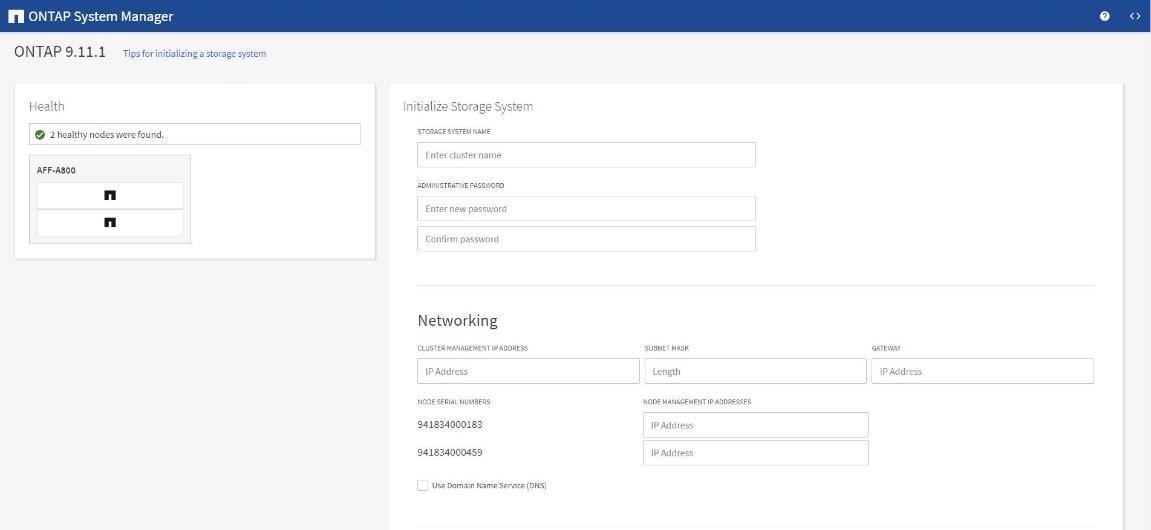
Step 5. In the Cluster screen:
a. Enter the cluster name and administrator password.
b. Complete the Networking information for the cluster and each node.
c. Check the box for Use Domain Name Service (DNS) and enter the IP addresses of the DNS servers in a comma separated list.
d. Check the box for Use time services (NTP) and enter the IP addresses of the time servers in a comma separated list.
Note: Here, the DNS and NTP server manual configuration for the cluster is optional. Ansible scripts will configure the same when NetApp ONTAP playbook with the tag “ontap_config_part_1” is executed.
Note: The nodes should be discovered automatically; if they are not, Refresh the browser page. By default, the cluster interfaces are created on all the new factory shipping storage controllers.
Note: If all the nodes are not discovered, then configure the cluster using the command line.
Note: The node management interface can be on the same subnet as the cluster management interface, or it can be on a different subnet. In this document, we assume that it is on the same subnet.
Step 6. Click Submit.
Step 7. A few minutes will pass while the cluster is configured. When prompted, login to NetApp ONTAP System Manager to continue the cluster configuration.
Procedure 4. Manual NetApp ONTAP Storage Configuration - Part 1
Step 1. From the Dashboard click the Cluster menu on the left and select Overview.
Step 2. Click the More ellipsis button in the Overview pane at the top right of the screen and select Edit.
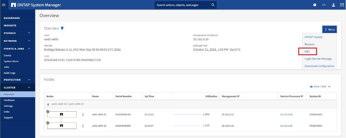
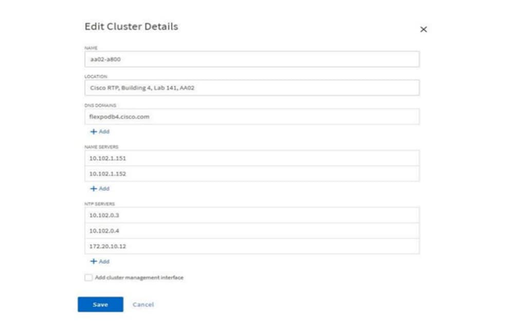
Step 3. Add additional cluster configuration details and click Save to make the changes persistent:
a. Cluster location
b. DNS domain name
c. DNS server IP addresses
d. NTP server IP addresses
Note: DNS and NTP server IP addresses can be added individually or with a comma separated list on a single line.
Note: For redundancy and best service NetApp recommends that you associate at least three NTP servers with the cluster. Otherwise, the user will observe an alert/warning in AIQUM stating “NTP Server Count is Low.”
Step 4. Click Save to make the changes persistent.
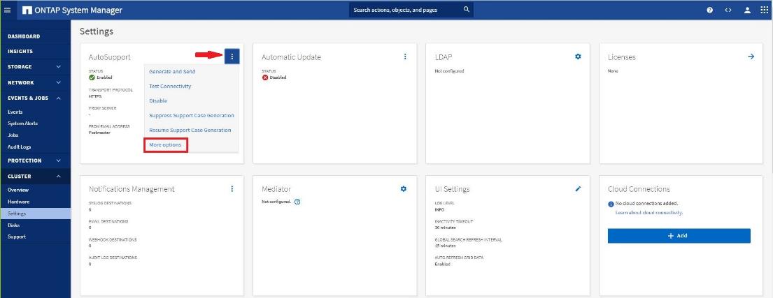
Step 5. Select the Settings menu under the Cluster menu.
Step 6. If AutoSupport was not configured during the initial setup, click the ellipsis in the AutoSupport tile and select More options.
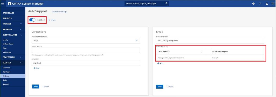
Step 7. To enable AutoSupport click the slider.
Step 8. Click Edit to change the transport protocol, add a proxy server address and a mail host as needed.
Step 9. Click Save to enable the changes.
Step 10. In the Email tile to the right, click Edit and enter the desired email information:
a. Email send from address
b. Email recipient addresses
c. Recipient Category
Step 11. Click Save when complete.
Step 12. Select CLUSTER > Settings at the top left of the page to return to the cluster settings page.
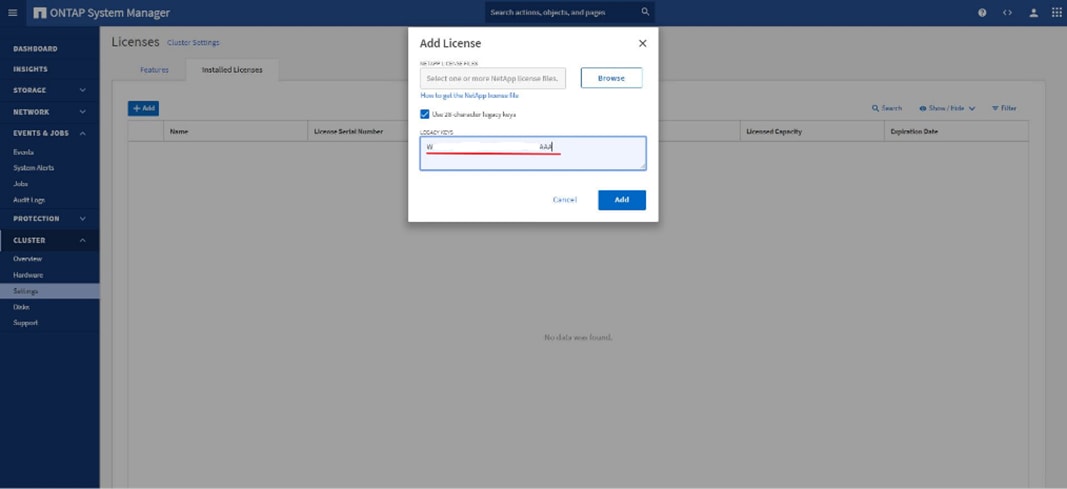
Step 13. Locate the Licenses tile on the right and click the detail arrow.
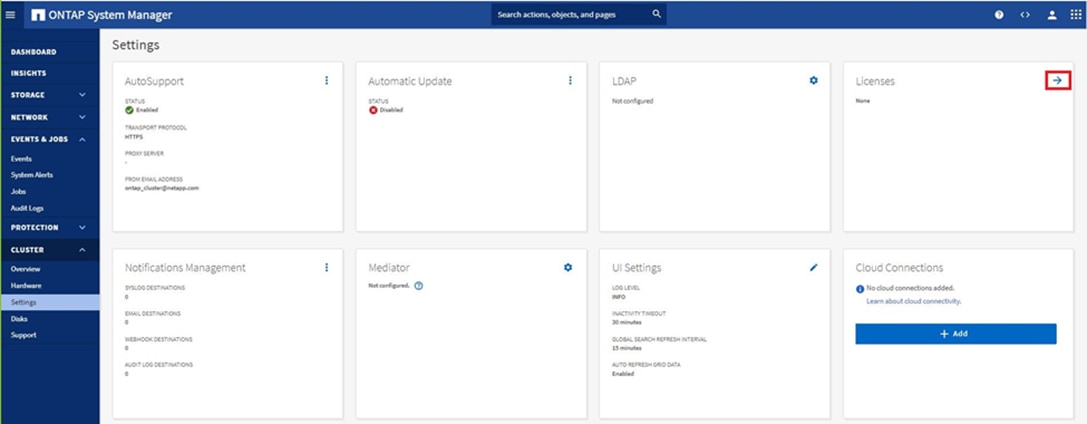
Step 14. Add the desired licenses to the cluster by clicking Add and entering the license keys in a comma separated list.
Note: NetApp ONTAP 9.10.1 and later for FAS/AFF storage systems uses a new file-based licensing solution to enable per-node NetApp ONTAP features. The new license key format is referred to as a NetApp License File, or NLF. For more information, refer to this URL: NetApp ONTAP 9.10.1 and later Licensing Overview - NetApp Knowledge Base
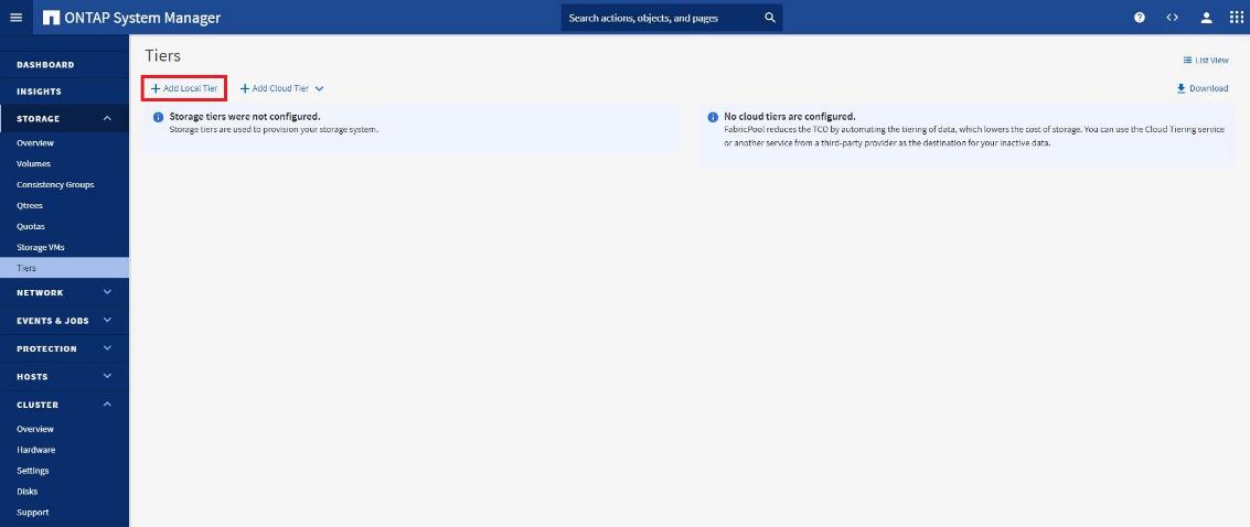
Step 15. Configure storage aggregates by selecting the Storage menu on the left and selecting Tiers.
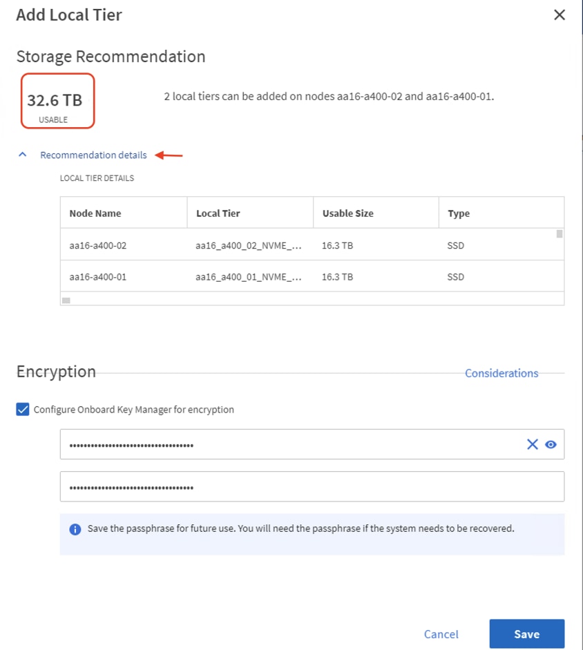
Step 16. Click Add Local Tier and allow NetApp ONTAP System Manager to recommend a storage aggregate configuration.
Step 17. NetApp ONTAP will use best practices to recommend an aggregate layout. Click the Recommended details link to view the aggregate information.
Step 18. Optionally, enable NetApp Aggregate Encryption (NAE) by checking the box for Configure Onboard Key Manager for encryption.
Step 19. Enter and confirm the passphrase and save it in a secure location for future use.
Step 20. Click Save to make the configuration persistent.
Note: Aggregate encryption may not be supported for all deployments. Please review the NetApp Encryption Power Guide and the Security Hardening Guide for NetApp ONTAP 9 (TR-4569) to help determine if aggregate encryption is right for your environment.
Procedure 5. Log into the Cluster
Step 1. Open an SSH connection to either the cluster IP or the host name.
Step 2. Log into the admin user with the password you provided earlier.
Procedure 6. Verify Storage Failover
Step 1. Verify the status of the storage failover.
storage failover show
Note: Both <st-node01> and <st-node02> must be capable of performing a takeover. Continue with step 2 if the nodes can perform a takeover.
Step 2. Enable failover on one of the two nodes if it was not completed during the installation.
storage failover modify -node <st-node01> -enabled true
Note: Enabling failover on one node enables it for both nodes.
Step 3. Verify the HA status for a two-node cluster.
Note: This step is not applicable for clusters with more than two nodes.
cluster ha show
Step 4. If HA is not configured use the below commands. Only enable HA mode for two-node clusters. Do not run this command for clusters with more than two nodes because it causes problems with failover.
cluster ha modify -configured true
Do you want to continue? {y|n}: y
Step 5. Verify that hardware assist is correctly configured.
storage failover hwassist show
Step 6. If hwassist storage failover is not enabled, enable using the following commands:
storage failover modify –hwassist-partner-ip <node02-mgmt-ip> -node <st-node01>
storage failover modify –hwassist-partner-ip <node01-mgmt-ip> -node <st-node02>
Procedure 7. Set Auto-Revert Parameter on Cluster Management Interface
Step 1. Run the following command:
network interface modify -vserver <clustername> -lif cluster_mgmt_lif -auto-revert true
Note: A storage virtual machine (SVM) is referred to as a Vserver or vserver in the GUI and CLI.
Procedure 8. Zero All Spare Disks
Step 1. To zero all spare disks in the cluster, run the following command:
disk zerospares
Note: Advanced Data Partitioning creates a root partition and two data partitions on each SSD drive in an AFF configuration. Disk auto-assign should have assigned one data partition to each node in an HA pair. If a different disk assignment is required, disk auto-assignment must be disabled on both nodes in the HA pair by running the disk option modify command. Spare partitions can then be moved from one node to another by running the disk removeowner and disk assign commands.
Procedure 9. Set Up Service Processor Network Interface
Step 1. To assign a static IPv4 address to the Service Processor on each node, run the following commands:
system service-processor network modify –node <st-node01> -address-family IPv4 –enable true –dhcp none –ip-address <node01-sp-ip> -netmask <node01-sp-mask> -gateway <node01-sp-gateway>
system service-processor network modify –node <st-node02> -address-family IPv4 –enable true –dhcp none –ip-address <node02-sp-ip> -netmask <node02-sp-mask> -gateway <node02-sp-gateway>
Note: The Service Processor IP addresses should be in the same subnet as the node management IP addresses.
Procedure 10. Create Manual Provisioned Aggregates (Optional)
An aggregate containing the root volume is created during the NetApp ONTAP setup process. To manually create additional aggregates, determine the aggregate name, the node on which to create it, and the number of disks it should contain. Options for disk type include SAS, SSD, and SSD-NVM.
Step 1. To create new aggregates, run the following commands:
storage aggregate create -aggregate <aggr1_node01> -node <st-node01> -diskcount <num-disks> -disktype SSD-NVM
storage aggregate create -aggregate <aggr1_node02> -node <st-node02> -diskcount <num-disks> -disktype SSD-NVM
Note: Customer should have the minimum number of hot spare disks for the recommended hot spare disk partitions for their aggregate.
Note: For all-flash aggregates, you should have a minimum of one hot spare disk or disk partition. For non-flash homogenous aggregates, you should have a minimum of two hot spare disks or disk partitions. For Flash Pool aggregates, you should have a minimum of two hot spare disks or disk partitions for each disk type.
Note: In an AFF configuration with a small number of SSDs, you might want to create an aggregate with all, but one remaining disk (spare) assigned to the controller.
Note: The aggregate cannot be created until disk zeroing completes. Run the storage aggregate show command to display the aggregate creation status. Do not proceed until both aggr1_node01 and aggr1_node02 are online.
Procedure 11. Remove Default Broadcast Domains
By default, all network ports are included in separate default broadcast domain. Network ports used for data services (for example, e5a, e5b, and so on) should be removed from their default broadcast domain and that broadcast domain should be deleted.
Step 1. To perform this task, run the following commands:
network port broadcast-domain delete -broadcast-domain <Default-N> -ipspace Default
network port broadcast-domain show
Note: Delete the Default broadcast domains with Network ports (Default-1, Default-2, and so on). This does not include Cluster ports and management ports.
Procedure 12. Disable Flow Control on 25/100GbE Data Ports
Step 1. Run the following command to configure the ports on node 01:
network port modify -node <st-node01> -port e5a,e5b -flowcontrol-admin none
Step 2. Run the following command to configure the ports on node 02:
network port modify -node <st-node02> -port e5a,e5b -flowcontrol-admin none
Note: Disable flow control only on ports that are used for data traffic.
Procedure 13. Disable Auto-Negotiate on Fibre Channel Ports (Required only for FC configuration)
Step 1. Disable each FC adapter in the controllers with the fcp adapter modify command.
fcp adapter modify -node <st-node01> -adapter 2a –status-admin down
fcp adapter modify -node <st-node01> -adapter 2b –status-admin down
fcp adapter modify -node <st-node02> -adapter 2a –status-admin down
fcp adapter modify -node <st-node02> -adapter 2b –status-admin down
Step 2. Set the desired speed on the adapter and return it to the online state.
fcp adapter modify -node <st-node01> -adapter 2a -speed 32 -status-admin up
fcp adapter modify -node <st-node01> -adapter 2b -speed 32 -status-admin up
fcp adapter modify -node <st-node02> -adapter 2a -speed 32 -status-admin up
fcp adapter modify -node <st-node02> -adapter 2b -speed 32 -status-admin up
Procedure 14. Enable Cisco Discovery Protocol
Step 1. To enable the Cisco Discovery Protocol (CDP) on the NetApp storage controllers, run the following command:
node run -node * options cdpd.enable on
Procedure 15. Enable Link-layer Discovery Protocol on all Ethernet Ports
Step 1. Enable LLDP on all ports of all nodes in the cluster:
node run * options lldp.enable on
Procedure 16. Configure Timezone
To configure time synchronization on the cluster, follow these steps:
Step 1. Set the time zone for the cluster.
timezone -timezone <timezone>
Note: For example, in the eastern United States, the time zone is America/New_York.
Procedure 17. Configure Simple Network Management Protocol
Step 1. Configure basic SNMP information, such as the location and contact. When polled, this information is visible as the sysLocation and sysContact variables in SNMP.
snmp contact <snmp-contact>
snmp location <snmp-location>
snmp init 1
options snmp.enable on
Step 2. Configure SNMP traps to send to remote hosts, such as an Active IQ Unified Manager server or another fault management system.
snmp traphost add <oncommand-um-server-fqdn>
Step 3. Configure SNMP community.
system snmp community add -type ro -community-name <snmp-community> -vserver <clustername>
Note: In new installations of NetApp ONTAP, SNMPv1 and SNMPv2c are disabled by default. SNMPv1 and SNMPv2c are enabled after you create an SNMP community.
Note: NetApp ONTAP supports read-only communities.
Procedure 18. Configure SNMPv3 Access
SNMPv3 offers advanced security by using encryption and passphrases. The SNMPv3 users can run SNMP utilities from the traphost using the authentication and privacy settings that they specify.
Step 1. To configure SNMPv3 access, run the following commands:
security login create -user-or-group-name <<snmp-v3-usr>> -application snmp -authentication-method usm
Enter the authoritative entity's EngineID [local EngineID]:
Which authentication protocol do you want to choose (none, md5, sha, sha2-256) [none]: <<snmp-v3-auth-proto>>
Enter the authentication protocol password (minimum 8 characters long):
Enter the authentication protocol password again:
Which privacy protocol do you want to choose (none, des, aes128) [none]: <<snmpv3-priv-proto>>
Enter privacy protocol password (minimum 8 characters long):
Enter privacy protocol password again:
Note: Refer to the SNMP Configuration Express Guide for additional information when configuring SNMPv3 security users.
Procedure 19. Configure login banner for the NetApp ONTAP Cluster
Step 1. To create login banner for the NetApp ONTAP cluster, run the following command:
security login banner modify -message "Access restricted to authorized users" -vserver <clustername>
Note: If the login banner for the cluster is not configured, users will observe a warning in AIQUM stating “Login Banner Disabled.”
Procedure 20. Enable FIPS Mode on the NetApp ONTAP Cluster
NetApp ONTAP is compliant in the Federal Information Processing Standards (FIPS) 140-2 for all SSL connections. When SSL FIPS mode is enabled, SSL communication from NetApp ONTAP to external client or server components outside of NetApp ONTAP will use FIPS compliant crypto for SSL.
Step 2. To enable FIPS on the NetApp ONTAP cluster, run the following commands:
set -privilege advanced
security config modify -interface SSL -is-fips-enabled true
Note: If you are running NetApp ONTAP 9.8 or earlier manually reboot each node in the cluster one by one. Beginning in NetApp ONTAP 9.9.1, rebooting is not required.
Note: If FIPS is not enabled on the NetApp ONTAP cluster, the users will observe a warning in AIQUM stating “FIPS Mode Disabled.”
Procedure 21. Remove insecure ciphers from the NetApp ONTAP Cluster
Step 1. Ciphers with the suffix CBC are considered insecure. To remove the CBC ciphers, run the following NetApp ONTAP command:
security ssh remove -vserver <clustername> -ciphers aes256-cbc,aes192-cbc,aes128-cbc,3des-cbc
Note: If the users do not perform the above task, they will see a warning in AIQUM saying “SSH is using insecure ciphers.”
Procedure 22. Create Management Broadcast Domain
Step 1. If the management interfaces are required to be on a separate VLAN, create a new broadcast domain for those interfaces by running the following command:
network port broadcast-domain create -broadcast-domain IB-MGMT -mtu 1500
Procedure 23. Create NFS Broadcast Domain
Step 1. To create an NFS data broadcast domain with a maximum transmission unit (MTU) of 9000, run the following commands in NetApp ONTAP:
network port broadcast-domain create -broadcast-domain Infra-NFS -mtu 9000
Procedure 24. Create ISCSI Broadcast Domains (Required only for iSCSI configuration)
Step 1. To create an ISCSI-A and ISCSI-B data broadcast domain with a maximum transmission unit (MTU) of 9000, run the following commands in NetApp ONTAP:
network port broadcast-domain create -broadcast-domain Infra-ISCSI-A -mtu 9000
network port broadcast-domain create -broadcast-domain Infra-ISCSI-B -mtu 9000
Procedure 25. Create NVMe/TCP Broadcast Domains (Required only for NVMe/TCP configuration)
Step 1. To create NVMe-TCP-A and NVMe-TCP-B data broadcast domain with a maximum transmission unit (MTU) of 9000, run the following commands in NetApp ONTAP:
network port broadcast-domain create -broadcast-domain Infra-NVMe-TCP-A -mtu 9000
network port broadcast-domain create -broadcast-domain Infra-NVMe-TCP-B -mtu 9000
Procedure 26. Create Interface Groups
Step 1. To create the LACP interface groups for the 25GbE data interfaces, run the following commands:
network port ifgrp create -node <st-node01> -ifgrp a0a -distr-func port -mode multimode_lacp
network port ifgrp add-port -node <st-node01> -ifgrp a0a -port e5a
network port ifgrp add-port -node <st-node01> -ifgrp a0a -port e5b
network port ifgrp create -node <st-node02> -ifgrp a0a -distr-func port -mode multimode_lacp
network port ifgrp add-port -node <st-node02> -ifgrp a0a -port e5a
network port ifgrp add-port -node <st-node02> -ifgrp a0a -port e5b
Procedure 27. Change MTU on Interface Groups
Step 1. To change the MTU size on the base interface-group ports before creating the VLAN ports, run the following commands:
network port modify –node <st-node01> -port a0a –mtu 9000
network port modify –node <st-node02> -port a0a –mtu 9000
Step 1. Create the management VLAN ports and add them to the management broadcast domain.
network port vlan create –node <st-node01> -vlan-name a0a-<ib-mgmt-vlan-id>
network port vlan create –node <st-node02> -vlan-name a0a-<ib-mgmt-vlan-id>
network port broadcast-domain add-ports -broadcast-domain IB-MGMT -ports <st-node01>:a0a-<ib-mgmt-vlan-id>,<st-node02>:a0a-<ib-mgmt-vlan-id>
Step 2. Create the NFS VLAN ports and add them to the Infra-NFS broadcast domain.
network port vlan create –node <st-node01> -vlan-name a0a-<infra-nfs-vlan-id>
network port vlan create –node <st-node02> -vlan-name a0a-<infra-nfs-vlan-id>
network port broadcast-domain add-ports -broadcast-domain Infra-NFS -ports <st-node01>:a0a-<infra-nfs-vlan-id>,<st-node02>:a0a-<infra-nfs-vlan-id>
Step 3. If configuring iSCSI, create iSCSI VLAN ports for the iSCSI LIFs on each storage controller and add them to the corresponding broadcast domain:
network port vlan create -node <st-node01> -vlan-name a0a-<infra-iscsi-a-vlan-id>
network port vlan create -node <st-node01> -vlan-name a0a-<infra-iscsi-b-vlan-id>
network port vlan create -node <st-node02> -vlan-name a0a-<infra-iscsi-a-vlan-id>
network port vlan create -node <st-node02> -vlan-name a0a-<infra-iscsi-b-vlan-id>
network port broadcast-domain add-ports -broadcast-domain Infra-iSCSI-A -ports <st-node01>:a0a-<infra-iscsi-a-vlan-id>
network port broadcast-domain add-ports -broadcast-domain Infra-iSCSI-B -ports <st-node01>:a0a-<infra-iscsi-b-vlan-id>
network port broadcast-domain add-ports -broadcast-domain Infra-iSCSI-A -ports <st-node02>:a0a-<infra-iscsi-a-vlan-id>
network port broadcast-domain add-ports -broadcast-domain Infra-iSCSI-B -ports <st-node02>:a0a-<infra-iscsi-b-vlan-id>
Step 4. If configuring NVMe/TCP, create NVMe/TCP VLAN ports for the NVMe/TCP LIFs on each storage controller and add them to the corresponding broadcast domain:
network port vlan create -node <st-node01> -vlan-name a0a-<infra-nvme-tcp-a-vlan-id>
network port vlan create -node <st-node01> -vlan-name a0a-<infra-nvme-tcp-b-vlan-id>
network port vlan create -node <st-node02> -vlan-name a0a-<infra-nvme-tcp-a-vlan-id>
network port vlan create -node <st-node02> -vlan-name a0a-<infra-nvme-tcp-b-vlan-id>
network port broadcast-domain add-ports -broadcast-domain Infra-NVMe-TCP-A -ports <st-node01>:a0a-<infra-nvme-tcp-a-vlan-id>
network port broadcast-domain add-ports -broadcast-domain Infra-NVMe-TCP-B -ports <st-node01>:a0a-<infra-nvme-tcp-b-vlan-id>
network port broadcast-domain add-ports -broadcast-domain Infra-NVMe-TCP-A -ports <st-node02>:a0a-<infra- nvme-tcp-a-vlan-id>
network port broadcast-domain add-ports -broadcast-domain Infra-NVMe-TCP-B -ports <st-node02>:a0a-<infra- nvme-tcp-b-vlan-id>
Procedure 29. Create SVM (Storage Virtual Machine)
Step 1. Run the vserver create command.
vserver create –vserver Infra-SVM –rootvolume infra_svm_root –aggregate aggr1_node01 –rootvolume-security-style unix
Step 2. Add the required data protocols to the SVM:
vserver add-protocols -protocols nfs,iscsi,fcp,nvme -vserver Infra-SVM
Note: For FC-NVMe configuration, add “fcp” and “nvme” protocols to the SVM.
Note: For NVMe/TCP configuration with iSCSI booting, add “nvme” and “iscsi” protocols to the SVM.
Step 3. Remove the unused data protocols from the SVM:
vserver remove-protocols –vserver Infra-SVM -protocols cifs
Note: It is recommended to remove iSCSI or FCP protocols if the protocol is not in use.
Step 4. Add the two data aggregates to the Infra-SVM aggregate list for the NetApp ONTAP Tools.
vserver modify –vserver Infra-SVM –aggr-list <aggr1_node01>,<aggr1_node02>
Step 5. Enable and run the NFS protocol in the Infra-SVM.
vserver nfs create -vserver Infra-SVM -udp disabled -v3 enabled -v4.1 enabled -vstorage enabled
Note: If the NFS license was not installed during the cluster configuration, make sure to install the license before starting the NFS service.
Step 6. Verify that the NFS vstorage parameter for the NetApp NFS VAAI plug-in was enabled.
aa02-a800::> vserver nfs show -fields vstorage
vserver vstorage
--------- --------
Infra-SVM enabled
Procedure 30. Vserver Protocol Verification
Step 1. Verify the required protocols are added to the Infra-SVM vserver.
aa02-a800::> vserver show-protocols -vserver Infra-SVM
Vserver: Infra-SVM
Protocols: nfs, fcp, iscsi, nvme
Step 2. If a protocol is not present, use the following command to add the protocol to the vserver:
vserver add-protocols -vserver <infra-data-svm> -protocols <iscsi or fcp>
Procedure 31. Create Load-Sharing Mirrors of SVM Root Volume
Step 1. Create a volume to be the load-sharing mirror of the infrastructure SVM root volume on each node.
volume create –vserver Infra-SVM –volume infra_svm_root_m01 –aggregate <aggr1_node01> –size 1GB –type DP
volume create –vserver Infra-SVM –volume infra_svm_root_m02 –aggregate <aggr1_node02> –size 1GB –type DP
Step 2. Create a job schedule to update the root volume mirror relationships every 15 minutes.
job schedule interval create -name 15min -minutes 15
Step 3. Create the mirroring relationships.
snapmirror create –source-path Infra-SVM:infra_svm_root -destination-path Infra-SVM:infra_svm_root_m01 –type LS -schedule 15min
snapmirror create –source-path Infra-SVM:infra_svm_root –destination-path Infra-SVM:infra_svm_root_m02 –type LS -schedule 15min
Step 4. Initialize the mirroring relationship.
snapmirror initialize-ls-set –source-path Infra-SVM:infra_svm_root
Procedure 32. Create FC Block Protocol Service (required only for FC configuration)
Step 1. Run the following command to create the FCP service. This command starts the FCP service and also sets the worldwide name (WWN) for the SVM:
vserver fcp create -vserver Infra-SVM -status-admin up
To verify:
aa02-a800::> vserver fcp show
Status
Vserver Target Name Admin
---------- ---------------------------- ------
Infra-SVM 20:00:00:a0:98:e2:17:ca up
Note: If the FC license was not installed during the cluster configuration, make sure to install the license before creating the FC service.
Procedure 33. Create iSCSI Block Protocol Service (required only for iSCSI configuration)
Step 1. Run the following command to create the iSCSI service:
vserver iscsi create -vserver Infra-SVM -status-admin up
To verify:
aa02-a800::> vserver iscsi show
Target Target Status
Vserver Name Alias Admin
---------- -------------------------------- ---------------------------- ------
Infra-SVM iqn.1992-08.com.netapp:sn.90e9cb71515311ed978d00a098e217cb:vs.3
Infra-SVM up
Note: If the iSCSI license was not installed during the cluster configuration, make sure to install the license before creating the iSCSI service.
Procedure 34. Create NVMe Service (required only for FC-NVMe and NVMe/TCP configuration)
Step 1. Verify NVMe Capable adapters are installed in the cluster.
network fcp adapter show -data-protocols-supported fc-nvme
Step 2. Make sure that the “nvme” protocol is added to the SVM.
aa02-a800::> vserver show-protocols -vserver Infra-SVM
Vserver: Infra-SVM
Protocols: nfs, fcp, iscsi, nvme
Step 3. Create NVMe service.
vserver nvme create -vserver Infra-SVM -status-admin up
To verify:
aa02-a800::> vserver nvme show -vserver Infra-SVM
Vserver Name: Infra-SVM
Administrative Status: up
Discovery Subsystem NQN: nqn.1992-08.com.netapp:sn.90e9cb71515311ed978d00a098e217cb:discovery
Note: If the NVMe license was not installed during the cluster configuration, make sure to install the license before creating the NVMe service.
Procedure 35. Configure HTTPS access
Step 1. Increase the privilege level to access the certificate commands.
set -privilege diag
Do you want to continue? {y|n}: y
Step 2. Generally, a self-signed certificate is already in place. Verify the certificate and obtain parameters (for example, the <serial-number>) by running the following command:
security certificate show
Step 3. For each SVM shown, the certificate common name should match the DNS fully qualified domain name (FQDN) of the SVM. Delete the two default certificates and replace them with either self-signed certificates or certificates from a certificate authority (CA). To delete the default certificates, run the following commands:
security certificate delete -vserver Infra-SVM -common-name Infra-SVM -ca Infra-SVM -type server -serial <serial-number>
Note: Deleting expired certificates before creating new certificates is a best practice. Run the security certificate delete command to delete the expired certificates. In the following command, use TAB completion to select and delete each default certificate.
Step 4. To generate and install self-signed certificates, run the following commands as one-time commands. Generate a server certificate for the Infra-SVM and the cluster SVM. Use TAB completion to aid in the completion of these commands.
security certificate create -common-name <cert-common-name> -type server -size 2048 -country <cert-country> -state <cert-state> -locality <cert-locality> -organization <cert-org> -unit <cert-unit> -email-addr <cert-email> -expire-days <cert-days> -protocol SSL -hash-function SHA256 -vserver Infra-SVM
Step 5. To obtain the values for the parameters required in step 6 (<cert-ca> and <cert-serial>), run the security certificate show command.
Step 6. Enable each certificate that was just created by using the -server-enabled true and -client-enabled false parameters. Use TAB completion to aid in the completion of these commands.
security ssl modify -vserver <clustername> -server-enabled true -client-enabled false -ca <cert-ca> -serial <cert-serial> -common-name <cert-common-name>
Step 7. Disable HTTP cluster management access.
network interface service-policy remove-service -vserver <clustername> -policy default-management -service management-http
Note: It is normal for some of these commands to return an error message stating that the entry does not exist.
Note: The command system services firewall policy delete is deprecated and may be removed in a future NetApp ONTAP release. So, use the above command network interface service-policy remove-service instead.
Note: The above task is not yet implemented via Ansible as the concerned Ansible module is not available under NetApp ONTAP collections. So, this step needs to be done manually by the user.
Step 8. Change back to the normal admin privilege level and verify that the system logs are available in a web browser.
set –privilege admin
https://<node01-mgmt-ip>/spi
https://<node02-mgmt-ip>/spi
Procedure 36. Set password for SVM vsadmin user and unlock the user
Step 1. Set a password for the SVM vsadmin user and unlock the user using the following commands:
security login password –username vsadmin –vserver Infra-SVM
Enter a new password: <password>
Enter it again: <password>
security login unlock –username vsadmin –vserver Infra-SVM
Procedure 37. Configure login banner for the SVM
Step 1. To create login banner for the SVM, run the following command:
security login banner modify -vserver Infra-SVM -message "This Infra-SVM is reserved for authorized users only!"
Note: If the login banner for the SVM is not configured, users will observe a warning in AIQUM stating “Login Banner Disabled.”
Procedure 38. Remove insecure ciphers from the SVM
Step 1. Ciphers with the suffix CBC are considered insecure. To remove the CBC ciphers from the SVM, run the following NetApp ONTAP command:
security ssh remove -vserver Infra-SVM -ciphers aes256-cbc,aes192-cbc,aes128-cbc,3des-cbc
Note: If the users do not perform the above task, they will see a warning in AIQUM saying “SSH is using insecure ciphers.”
Procedure 39. Configure export policy rule
Step 1. Create a new rule for the infrastructure NFS subnet in the default export policy.
vserver export-policy rule create –vserver Infra-SVM -policyname default –ruleindex 1 –protocol nfs -clientmatch <infra-nfs-subnet-cidr> -rorule sys –rwrule sys -superuser sys –allow-suid true
Step 2. Assign the FlexPod export policy to the infrastructure SVM root volume.
volume modify –vserver Infra-SVM –volume infra_svm_root –policy default
Procedure 40. Create FlexVol Volumes
The following information is required to create a NetApp FlexVol volume:
● The volume name
● The volume size
● The aggregate on which the volume exists
Step 1. To create FlexVols for datastores, run the following commands:
volume create -vserver Infra-SVM -volume infra_datastore -aggregate <aggr1_node02> -size 1TB -state online -policy default -junction-path /infra_datastore -space-guarantee none -percent-snapshot-space 0
Step 2. To create swap volumes, run the following command:
volume create -vserver Infra-SVM -volume infra_swap -aggregate <aggr1_node01> -size 200GB -state online -
policy default -junction-path /infra_swap -space-guarantee none -percent-snapshot-space 0 -snapshot-policy
none
Step 3. To create a FlexVol for the boot LUNs of servers, run the following command:
volume create -vserver Infra-SVM -volume esxi_boot -aggregate <aggr1_node01> -size 1TB -state online -
policy default -space-guarantee none -percent-snapshot-space 0
Step 4. Create vCLS datastores to be used by the vSphere environment to host vSphere Cluster Services (vCLS) VMs using the command below:
volume create -vserver Infra-SVM -volume vCLS -aggregate <aggr1_node01> -size 100GB -state online -
policy default -junction-path /vCLS -space-guarantee none -percent-snapshot-space 0 -snapshot-policy none
Step 5. To configure NVMe datastores, run the following commands:
volume create -vserver Infra-SVM -volume NVMe_Datastore_01 -aggregate <aggr1_node01> -size 500G -state online -policy default -space-guarantee none -percent-snapshot-space 0
Note: To Configure NVMe Datastores for vSphere 7U3, enable the NVMe protocol on an existing SVM or create a separate SVM for NVMe workloads. In this deployment, Infra-SVM was used for NVMe datastore configuration.
Note: NVMe datastores created above can be utilized for both FC-NVMe and NVMe/TCP configurations.
Note: Make sure that the aggregate used for NVMe datastore creation uses the disks of type “SSD-NVM.”
Step 6. Run the following command to create a FlexVol for storing SVM audit log configuration:
volume create -vserver Infra-SVM -volume audit_log -aggregate <aggr1_node01> -size 50GB -state online -
policy default -junction-path /audit_log -space-guarantee none -percent-snapshot-space 0
Step 7. Update set of load-sharing mirrors using the command below:
snapmirror update-ls-set -source-path Infra-SVM:infra_svm_root
Note: If you are going to setup and use SnapCenter to backup the infra_datastore volume, add “-snapshot-policy none” to the end of the volume create command for the infra_datastore volume.
Procedure 41. Disable Volume Efficiency on swap volume
Step 1. On NetApp AFF systems, deduplication is enabled by default. To disable the efficiency policy on the infra_swap volume, run the following command:
volume efficiency off –vserver Infra-SVM –volume infra_swap
Step 1. To create NFS LIFs, run the following commands:
network interface create -vserver Infra-SVM -lif nfs-lif-01 -service-policy default-data-files -home-node <st-node01> -home-port a0a-<infra-nfs-vlan-id> –address <node01-nfs-lif-01-ip> -netmask <node01-nfs-lif-01-mask> -status-admin up –failover-policy broadcast-domain-wide –auto-revert true
network interface create -vserver Infra-SVM -lif nfs-lif-02 -service-policy default-data-files -home-node <st-node02> -home-port a0a-<infra-nfs-vlan-id> –address <node02-nfs-lif-02-ip> -netmask <node02-nfs-lif-02-mask>> -status-admin up –failover-policy broadcast-domain-wide –auto-revert true
To verify:
aa02-a800::> network interface show -vserver Infra-SVM -service-policy default-data-files
Logical Status Network Current Current Is
Vserver Interface Admin/Oper Address/Mask Node Port Home
----------- ---------- ---------- ------------------ ------------- ------- ----
Infra-SVM
nfs-lif-01 up/up 192.168.50.31/24 aa02-a800-01 a0a-3050 true
nfs-lif-02 up/up 192.168.50.32/24 aa02-a800-02 a0a-3050 true
2 entries were displayed.
Note: For the tasks using network interface create command, the -role and -firewall-policy parameters have been deprecated and may be removed in a future version of NetApp ONTAP. Use the -service-policy parameter instead.
Procedure 43. Create FC LIFs (required only for FC configuration)
Step 1. Run the following commands to create four FC LIFs (two on each node):
network interface create -vserver Infra-SVM -lif fcp-lif-01a -data-protocol fcp -home-node <st-node01> -home-port 2a –status-admin up
network interface create -vserver Infra-SVM -lif fcp-lif-01b -data-protocol fcp -home-node <st-node01> -home-port 2b –status-admin up
network interface create -vserver Infra-SVM -lif fcp-lif-02a -data-protocol fcp -home-node <st-node02> -home-port 2a –status-admin up
network interface create -vserver Infra-SVM -lif fcp-lif-02b -data-protocol fcp -home-node <st-node02> -home-port 2b –status-admin up
To verify:
aa02-a800::> network interface show -vserver Infra-SVM -data-protocol fcp
Logical Status Network Current Current Is
Vserver Interface Admin/Oper Address/Mask Node Port Home
----------- ---------- ---------- ------------------ ------------- ------- ----
Infra-SVM
fcp-lif-01a up/up 20:01:00:a0:98:e2:17:ca
aa02-a800-01 2a true
fcp-lif-01b up/up 20:02:00:a0:98:e2:17:ca
aa02-a800-01 2b true
fcp-lif-02a up/up 20:03:00:a0:98:e2:17:ca
aa02-a800-02 2a true
fcp-lif-02b up/up 20:04:00:a0:98:e2:17:ca
aa02-a800-02 2b true
4 entries were displayed.
Procedure 44. Create iSCSI LIFs (required only for iSCSI configuration)
Step 1. To create four iSCSI LIFs, run the following commands (two on each node):
network interface create -vserver Infra-SVM -lif iscsi-lif-01a -service-policy default-data-iscsi -home-node <st-node01> -home-port a0a-<infra-iscsi-a-vlan-id> -address <st-node01-infra-iscsi-a–ip> -netmask <infra-iscsi-a-mask> -status-admin up
network interface create -vserver Infra-SVM -lif iscsi-lif-01b -service-policy default-data-iscsi -home-node <st-node01> -home-port a0a-<infra-iscsi-b-vlan-id> -address <st-node01-infra-iscsi-b–ip> -netmask <infra-iscsi-b-mask> –status-admin up
network interface create -vserver Infra-SVM -lif iscsi-lif-02a -service-policy default-data-iscsi -home-node <st-node02> -home-port a0a-<infra-iscsi-a-vlan-id> -address <st-node02-infra-iscsi-a–ip> -netmask <infra-iscsi-a-mask> –status-admin up
network interface create -vserver Infra-SVM -lif iscsi-lif-02b -service-policy default-data-iscsi -home-node <st-node02> -home-port a0a-<infra-iscsi-b-vlan-id> -address <st-node02-infra-iscsi-b–ip> -netmask <infra-iscsi-b-mask> –status-admin up
To verify:
aa02-a800::> network interface show -vserver Infra-SVM -service-policy default-data-iscsi
Logical Status Network Current Current Is
Vserver Interface Admin/Oper Address/Mask Node Port Home
----------- ---------- ---------- ------------------ ------------- ------- ----
Infra-SVM
iscsi-lif-01a
up/up 192.168.10.31/24 aa02-a800-01 a0a-3010
true
iscsi-lif-01b
up/up 192.168.20.31/24 aa02-a800-01 a0a-3020
true
iscsi-lif-02a
up/up 192.168.10.32/24 aa02-a800-02 a0a-3010
true
iscsi-lif-02b
up/up 192.168.20.32/24 aa02-a800-02 a0a-3020
true
4 entries were displayed.
Procedure 45. Create FC-NVMe LIFs (required only for FC-NVMe configuration)
Step 1. Run the following commands to create four FC-NVMe LIFs (two on each node):
network interface create -vserver Infra-SVM -lif fc-nvme-lif-01a -data-protocol fc-nvme -home-node <st-node01> -home-port 2c –status-admin up
network interface create -vserver Infra-SVM -lif fc-nvme-lif-01b -data-protocol fc-nvme -home-node <st-node01> -home-port 2d –status-admin up
network interface create -vserver Infra-SVM -lif fcp-nvme-lif-02a -data-protocol fc-nvme -home-node <st-node02> -home-port 2c –status-admin up
network interface create -vserver Infra-SVM -lif fcp-nvme-lif-02b -data-protocol fc-nvme -home-node <st-node02> -home-port 2d –status-admin up
To verify:
aa02-a800::> network interface show -vserver Infra-SVM -data-protocol fc-nvme
Logical Status Network Current Current Is
Vserver Interface Admin/Oper Address/Mask Node Port Home
----------- ---------- ---------- ------------------ ------------- ------- ----
Infra-SVM
fc-nvme-lif-01a
up/up 20:06:00:a0:98:e2:17:ca
aa02-a800-01 2c true
fc-nvme-lif-01b
up/up 20:07:00:a0:98:e2:17:ca
aa02-a800-01 2d true
fc-nvme-lif-02a
up/up 20:08:00:a0:98:e2:17:ca
aa02-a800-02 2c true
fc-nvme-lif-02b
up/up 20:09:00:a0:98:e2:17:ca
aa02-a800-02 2d true
4 entries were displayed.
Note: You can only configure two NVMe LIFs per node on a maximum of four nodes.
Procedure 46. Create NVMe/TCP LIFs (required only for NVMe/TCP configuration)
Step 1. To create four NVMe/TCP LIFs, run the following commands (two on each node):
network interface create -vserver Infra-SVM -lif nvme-tcp-01a -service-policy default-data-nvme-tcp -home-node <st-node01> -home-port a0a-<infra-nvme-tcp-a-vlan-id> -address <st-node01-infra-nvme-tcp-a–ip> -netmask <infra-nvme-tcp-a-mask> -status-admin up
network interface create -vserver Infra-SVM -lif nvme-tcp-01b -service-policy default-data-nvme-tcp -home-node <st-node01> -home-port a0a-<infra-nvme-tcp-b-vlan-id> -address <st-node01-infra-nvme-tcp-b–ip> -netmask <infra-nvme-tcp-b-mask> –status-admin up
network interface create -vserver Infra-SVM -lif nvme-tcp-02a -service-policy default-data-nvme-tcp -home-node <st-node02> -home-port a0a-<infra-nvme-tcp-a-vlan-id> -address <st-node02-infra-nvme-tcp-a–ip> -netmask <infra-nvme-tcp-a-mask> –status-admin up
network interface create -vserver Infra-SVM -lif nvme-tcp-02b -service-policy default-data-nvme-tcp -home-node <st-node02> -home-port a0a-<infra-nvme-tcp-b-vlan-id> -address <st-node02-infra-nvme-tcp-b–ip> -netmask <infra-nvme-tcp-b-mask> –status-admin up
To verify:
aa02-a800::> network interface show -vserver Infra-SVM -service-policy default-data-nvme-tcp
Logical Status Network Current Current Is
Vserver Interface Admin/Oper Address/Mask Node Port Home
----------- ---------- ---------- ------------------ ------------- ------- ----
Infra-SVM
nvme-tcp-01a up/up 192.168.30.31/24 aa02-a800-01 a0a-3030
true
nvme-tcp-01b up/up 192.168.40.31/24 aa02-a800-01 a0a-3040
true
nvme-tcp-02a up/up 192.168.30.32/24 aa02-a800-02 a0a-3030
true
nvme-tcp-02b up/up 192.168.40.32/24 aa02-a800-02 a0a-3040
true
4 entries were displayed.
Procedure 47. Create SVM management LIF (Add Infrastructure SVM Administrator)
Step 1. Run the following commands:
network interface create –vserver Infra-SVM –lif svm-mgmt -service-policy default-management –home-node <st-node01> -home-port a0a-<ib-mgmt-vlan-id> –address <svm-mgmt-ip> -netmask <svm-mgmt-mask> -status-admin up –failover-policy broadcast-domain-wide –auto-revert true
Step 2. Create a default route that enables the SVM management interface to reach the outside world.
network route create –vserver Infra-SVM -destination 0.0.0.0/0 –gateway <svm-mgmt-gateway>
To verify:
aa02-a800::> network route show -vserver Infra-SVM
Vserver Destination Gateway Metric
------------------- --------------- --------------- ------
Infra-SVM
0.0.0.0/0 10.102.1.254 20
Note: A cluster serves data through at least one and possibly several SVMs. These steps have been created for a single data SVM. Customers can create additional SVMs depending on their requirement.
Procedure 48. Configure AutoSupport
Step 1. NetApp AutoSupport sends support summary information to NetApp through HTTPS. To configure AutoSupport using command-line interface, run the following command:
system node autosupport modify -node * -state enable –mail-hosts <mailhost> -transport https -support enable -noteto <storage-admin-email>
Cisco Intersight Managed Mode Configuration
This chapter contains the following:
● Cisco Intersight Managed Mode Set Up
● Cisco UCS IMM Manual Configuration
● Cisco UCS IMM Setup Completion
The Cisco Intersight platform is a management solution delivered as a service with embedded analytics for Cisco and third-party IT infrastructures. The Cisco Intersight managed mode (also referred to as Cisco IMM or Intersight managed mode) is a new architecture that manages Cisco Unified Computing System (Cisco UCS) fabric interconnect–attached systems through a Redfish-based standard model. Cisco Intersight managed mode standardizes both policy and operation management for Cisco UCS B200 M6 and Cisco UCSX X210c M6 compute nodes used in this deployment guide.
Cisco UCS C-Series M6 servers, connected and managed through Cisco UCS FIs, are also supported by IMM. For a complete list of supported platforms, visit: https://www.cisco.com/c/en/us/td/docs/unified_computing/Intersight/b_Intersight_Managed_Mode_Configuration_Guide/b_intersight_managed_mode_guide_chapter_01010.html
Cisco Intersight Managed Mode Set Up
Procedure 1. Set up Cisco Intersight Managed Mode on Cisco UCS Fabric Interconnects
The Cisco UCS fabric interconnects need to be set up to support Cisco Intersight managed mode. When converting an existing pair of Cisco UCS fabric interconnects from Cisco UCS Manager mode to Intersight Mange Mode (IMM), first erase the configuration and reboot your system.
Note: Converting fabric interconnects to Cisco Intersight managed mode is a disruptive process, and configuration information will be lost. Customers are encouraged to make a backup of their existing configuration. If a software version that supports Intersight Managed Mode (4.1(3) or later) is already installed on Cisco UCS Fabric Interconnects, do not upgrade the software to a recommended recent release using Cisco UCS Manager. The software upgrade will be performed using Cisco Intersight to make sure Cisco UCS X-series firmware is part of the software upgrade.
Step 1. Configure Fabric Interconnect A (FI-A). On the Basic System Configuration Dialog screen, set the management mode to Intersight. All the remaining settings are similar to those for the Cisco UCS Manager managed mode (UCSM-Managed).
Cisco UCS Fabric Interconnect A
To configure the Cisco UCS for use in a FlexPod environment in ucsm managed mode, follow these steps:
1. Connect to the console port on the first Cisco UCS fabric interconnect.
Enter the configuration method. (console/gui) ? console
Enter the management mode. (ucsm/intersight)? intersight
The Fabric interconnect will be configured in the intersight managed mode. Choose (y/n) to proceed: y
Enforce strong password? (y/n) [y]: Enter
Enter the password for "admin": <password>
Confirm the password for "admin": <password>
Enter the switch fabric (A/B) []: A
Enter the system name: <ucs-cluster-name>
Physical Switch Mgmt0 IP address : <ucsa-mgmt-ip>
Physical Switch Mgmt0 IPv4 netmask : <ucs-mgmt-mask>
IPv4 address of the default gateway : <ucs-mgmt-gateway>
DNS IP address : <dns-server-1-ip>
Configure the default domain name? (yes/no) [n]: y
Default domain name : <ad-dns-domain-name>
Following configurations will be applied:
Management Mode=intersight
Switch Fabric=A
System Name=<ucs-cluster-name>
Enforced Strong Password=yes
Physical Switch Mgmt0 IP Address=<ucsa-mgmt-ip>
Physical Switch Mgmt0 IP Netmask=<ucs-mgmt-mask>
Default Gateway=<ucs-mgmt-gateway>
DNS Server=<dns-server-1-ip>
Domain Name=<ad-dns-domain-name>
Apply and save the configuration (select 'no' if you want to re-enter)? (yes/no): yes
Step 2. After applying the settings, make sure you can ping the fabric interconnect management IP address. When Fabric Interconnect A is correctly set up and is available, Fabric Interconnect B will automatically discover Fabric Interconnect A during its setup process as shown in the next step.
Step 3. Configure Fabric Interconnect B (FI-B). For the configuration method, select console. Fabric Interconnect B will detect the presence of Fabric Interconnect A and will prompt you to enter the admin password for Fabric Interconnect A. Provide the management IP address for Fabric Interconnect B and apply the configuration.
Cisco UCS Fabric Interconnect B
Enter the configuration method. (console/gui) ? console
Installer has detected the presence of a peer Fabric interconnect. This Fabric interconnect will be added to the cluster. Continue (y/n) ? y
Enter the admin password of the peer Fabric interconnect: <password>
Connecting to peer Fabric interconnect... done
Retrieving config from peer Fabric interconnect... done
Peer Fabric interconnect Mgmt0 IPv4 Address: <ucsa-mgmt-ip>
Peer Fabric interconnect Mgmt0 IPv4 Netmask: <ucs-mgmt-mask>
Peer FI is IPv4 Cluster enabled. Please Provide Local Fabric Interconnect Mgmt0 IPv4 Address
Physical Switch Mgmt0 IP address : <ucsb-mgmt-ip>
Apply and save the configuration (select 'no' if you want to re-enter)? (yes/no): yes
Procedure 2. Set up Cisco Intersight Account
Step 1. Go to https://intersight.com and click Create an account.
Step 2. Read and accept the license agreement. Click Next.
Step 3. Provide an Account Name and click Create.
Step 4. On successful creation of the Intersight account, following page will be displayed:
Note: You can also choose to add the Cisco UCS FIs to an existing Cisco Intersight account.
Procedure 3. Set up Cisco Intersight Licensing
Note: When setting up a new Cisco Intersight account (as explained in this document), the account needs to be enabled for Cisco Smart Software Licensing.
Step 1. Log into the Cisco Smart Licensing portal: https://software.cisco.com/software/smart-licensing/alerts.
Step 2. Verify that the correct virtual account is selected.
Step 3. Under Inventory > General, generate a new token for product registration.
Step 4. Copy this newly created token.
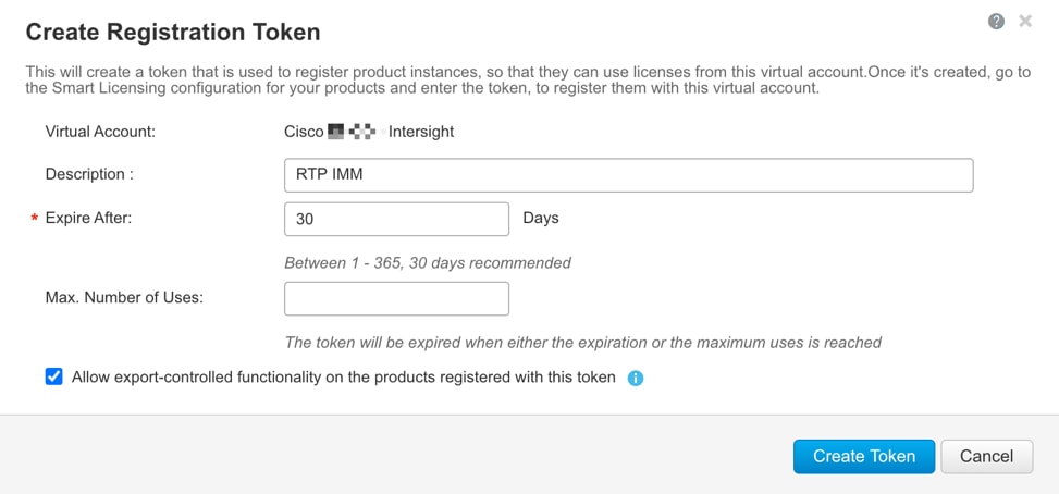
Step 5. In Cisco Intersight click Select Service > System, then click Administration > Licensing.
Step 6. Under Actions, click Register.
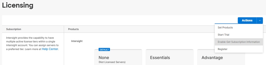
Step 7. Enter the copied token from the Cisco Smart Licensing portal. Click Next.
Step 8. Drop-down the pre-selected Default Tier * and select the license type (for example, Premier).
Step 9. Select Move All Servers to Default Tier.
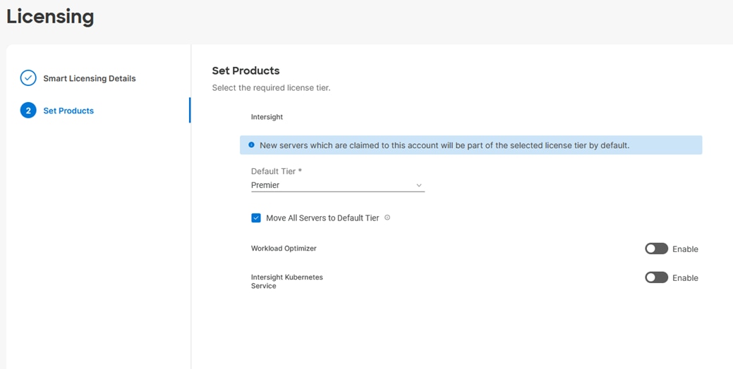
Step 10. Click Register, then click Register again.
Step 11. When the registration is successful (takes a few minutes), the information about the associated Cisco Smart account and default licensing tier selected in the last step is displayed.
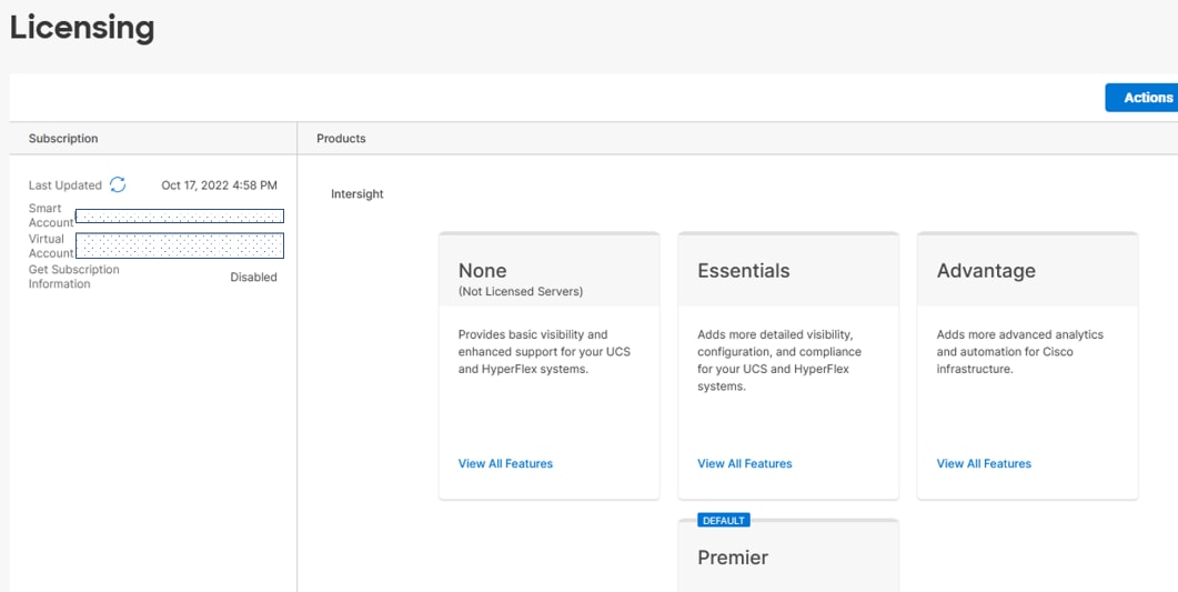
Procedure 4. Set Up Cisco Intersight Resource Group
In this procedure, a Cisco Intersight resource group is created where resources such as targets will be logically grouped. In this deployment, a single resource group is created to host all the resources, but customers can choose to create multiple resource groups for granular control of the resources.
Step 1. Log into Cisco Intersight.
Step 2. At the top, select System. On the left, click Settings (the gear icon).
Step 3. Click Resource Groups in the middle panel.
Step 4. Click + Create Resource Group in the top-right corner.
Step 5. Provide a name for the Resource Group (for example, AA02-rg).
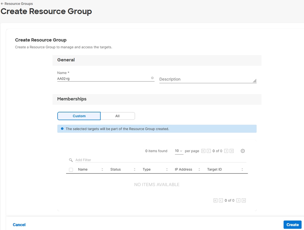
Step 6. Under Memberships, select Custom.
Step 7. Click Create.
Procedure 5. Set Up Cisco Intersight Organization
In this step, an Intersight organization is created where all Cisco Intersight managed mode configurations including policies are defined.
Step 1. Log into the Cisco Intersight portal.
Step 2. At the top, select System. On the left, click Settings (the gear icon).
Step 3. Click Organizations in the middle panel.
Step 4. Click + Create Organization in the top-right corner.
Step 5. Provide a name for the organization (for example, AA02).
Step 6. Select the Resource Group created in the last step (for example, AA02-rg).
Step 7. Click Create.
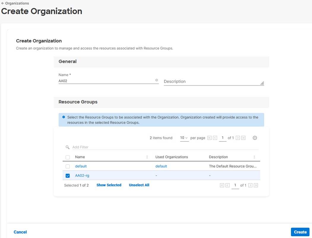
Procedure 6. Claim Cisco UCS Fabric Interconnects in Cisco Intersight
Make sure the initial configuration for the fabric interconnects has been completed. Log into the Fabric Interconnect A Device Console using a web browser to capture the Cisco Intersight connectivity information.
Step 1. Use the management IP address of Fabric Interconnect A to access the device from a web browser and the previously configured admin password to log into the device.
Step 2. Under DEVICE CONNECTOR, the current device status will show “Not claimed.” Note or copy, the Device ID, and Claim Code information for claiming the device in Cisco Intersight.
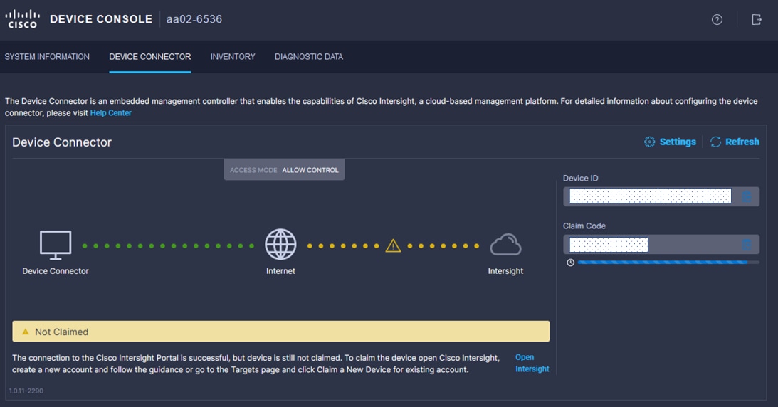
Step 3. Log into Cisco Intersight.
Step 4. At the top, select System. On the left, click Administration > Targets.
Step 5. Click Claim a New Target.
Step 6. Select Cisco UCS Domain (Intersight Managed) and click Start.
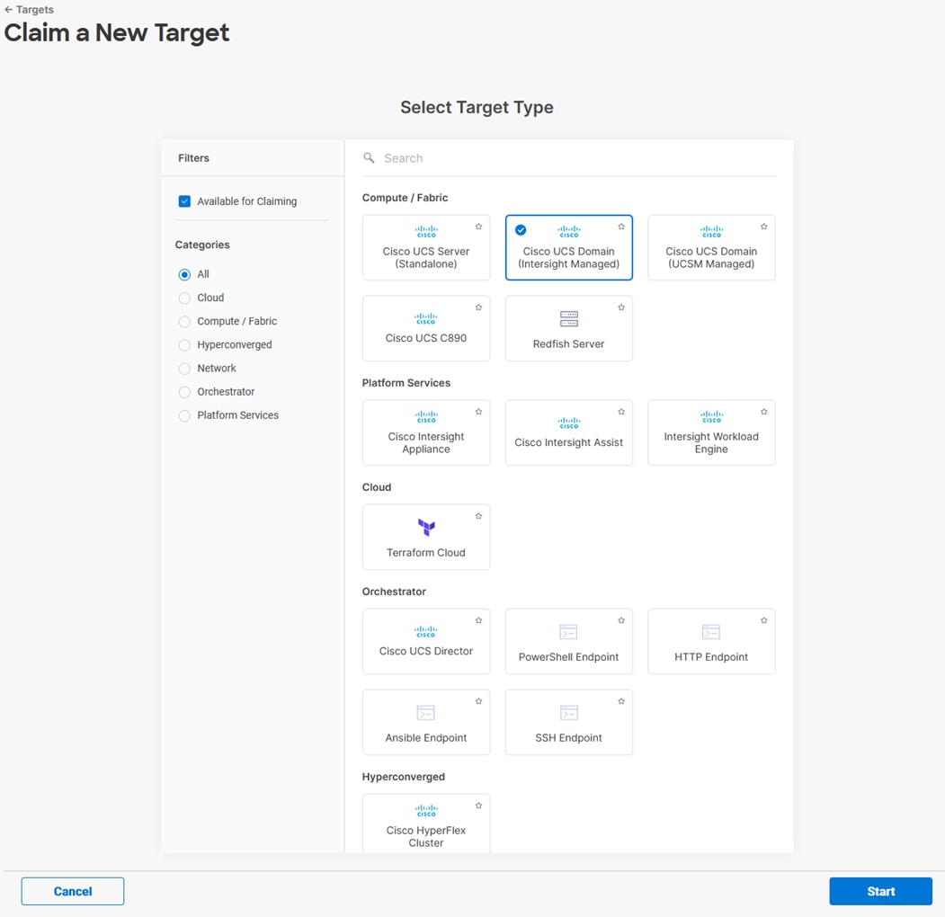
Step 7. Copy and paste the Device ID and Claim from the Cisco UCS FI to Intersight.
Step 8. Select the previously created Resource Group and click Claim.
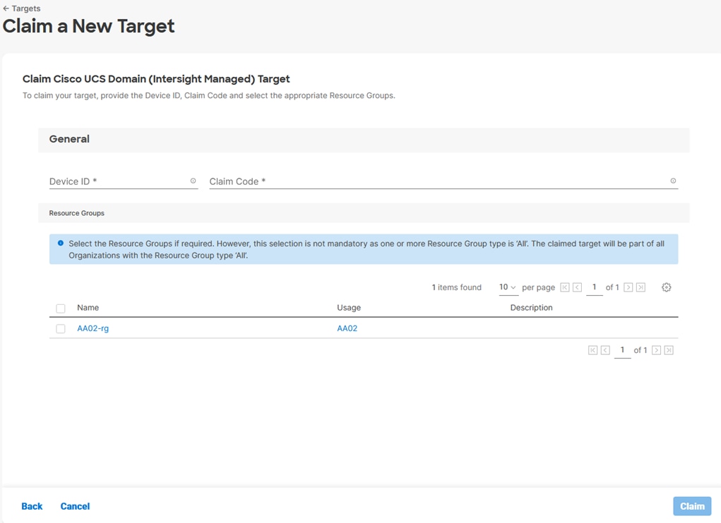
Step 9. With a successful device claim, Cisco UCS FI should appear as a target in Cisco Intersight.
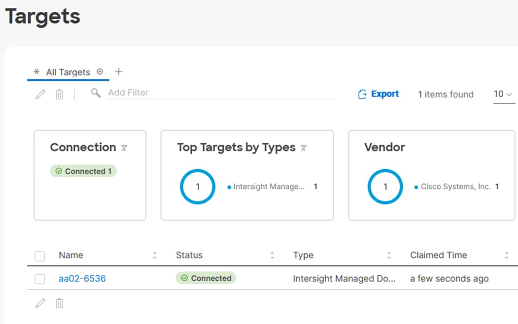
Procedure 7. Verify Addition of Cisco UCS Fabric Interconnects to Cisco Intersight
Step 1. Log into the web GUI of the Cisco UCS fabric interconnect and click the browser refresh button.
The fabric interconnect status should now be set to Claimed.
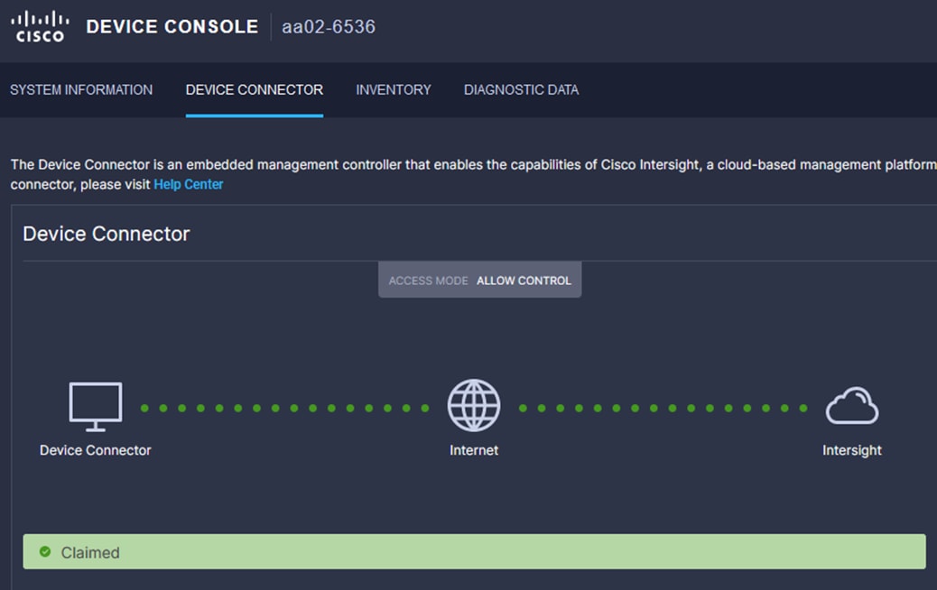
Procedure 8. Upgrade Fabric Interconnect Firmware using Cisco Intersight
Note: If your Cisco UCS 6536 Fabric Interconnects are not already running firmware release 4.2(2c) (NX-OS version 9.3(5)I42(2c)), upgrade them to 4.2(2c).
Note: If Cisco UCS Fabric Interconnects were upgraded to the latest recommended software using Cisco UCS Manager, this upgrade process through Intersight will still work and will copy the X-Series firmware to the Fabric Interconnects.
Step 1. Log into the Cisco Intersight portal.
Step 2. At the top, from the drop-down list,, select Infrastructure Service and then select Fabric Interconnects under Operate on the left.
Step 3. Click the ellipses “…” at the end of the row for either of the Fabric Interconnects and select Upgrade Firmware.
Step 4. Click Start.
Step 5. Verify the Fabric Interconnect information and click Next.
Step 6. Enable Advanced Mode using the toggle switch and uncheck Fabric Interconnect Traffic Evacuation.
Step 7. Select 4.2(2c) release from the list and click Next.
Step 8. Verify the information and click Upgrade to start the upgrade process.
Step 9. Keep an eye on the Request panel of the main Intersight screen as the system will ask for user permission before upgrading each FI. Click on the Circle with Arrow and follow the prompts on screen to grant permission.
Step 10. Wait for both the FIs to successfully upgrade.
Procedure 9. Configure a Cisco UCS Domain Profile
Note: A Cisco UCS domain profile configures a fabric interconnect pair through reusable policies, allows configuration of the ports and port channels, and configures the VLANs and VSANs in the network. It defines the characteristics of and configured ports on fabric interconnects. The domain-related policies can be attached to the profile either at the time of creation or later. One Cisco UCS domain profile can be assigned to one fabric interconnect domain.
Step 1. Log into the Cisco Intersight portal.
Step 2. At the top, use the pulldown to select Infrastructure Service. Then, under Configure select Profiles.
Step 3. In the main window, select UCS Domain Profiles and click Create UCS Domain Profile.
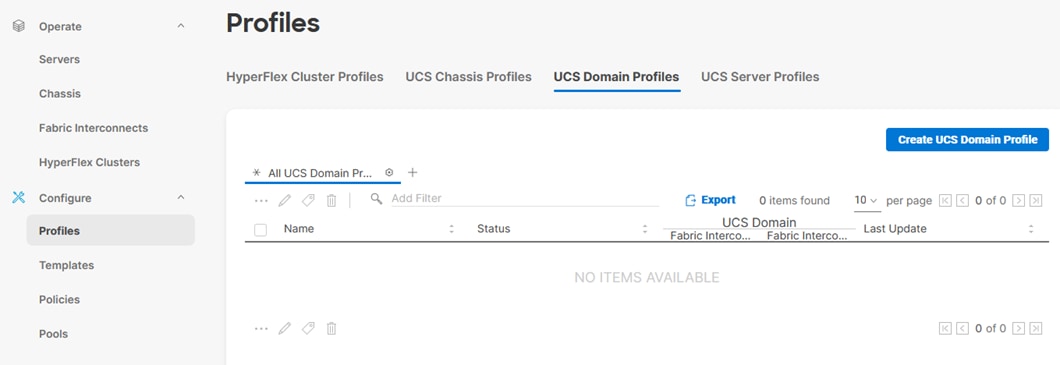
Step 4. On the Create UCS Domain Profile screen, click Start.
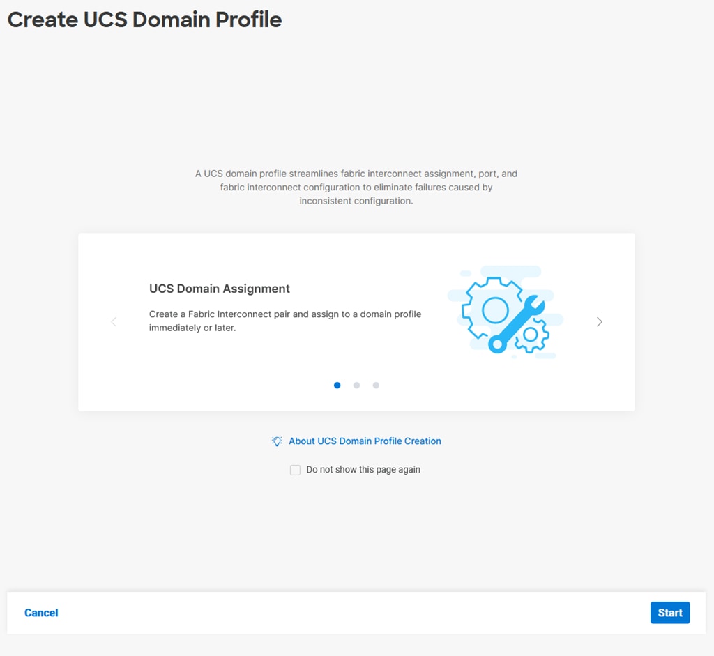
Procedure 10. General Configuration
Step 1. Select the organization from the drop-down list (for example, AA02).
Step 2. Provide a name for the domain profile (for example, AA02-6536-Domain-Profile).
Step 3. Provide an optional Description.
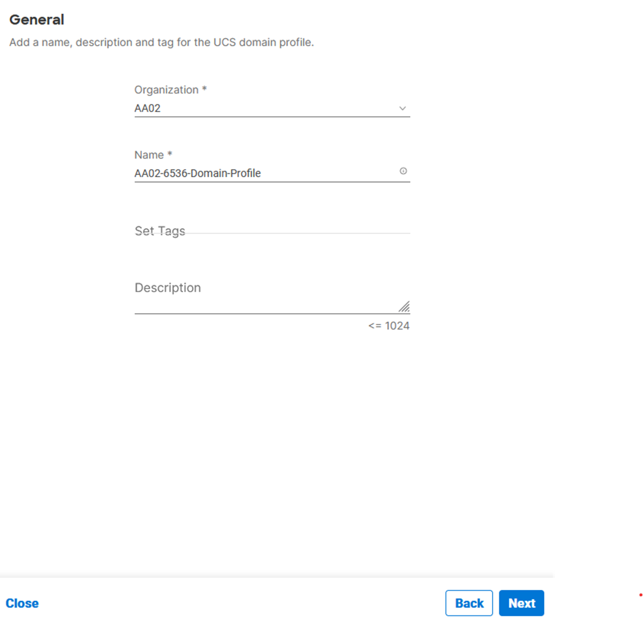
Step 4. Click Next.
Procedure 11. Cisco UCS Domain Assignment
Step 1. Assign the Cisco UCS domain to this new domain profile by clicking Assign Now and selecting the previously added Cisco UCS domain (for example, AA02-6536).
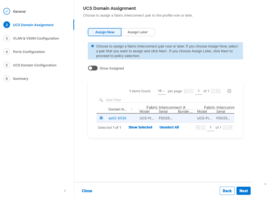
Step 2. Click Next.
In this procedure, a single VLAN policy is created for both fabric interconnects and two individual VSAN policies are created because the VSAN IDs are unique for each fabric interconnect.
Procedure 1. Create and Apply VLAN Policy
Step 1. Click Select Policy next to VLAN Configuration under Fabric Interconnect A.
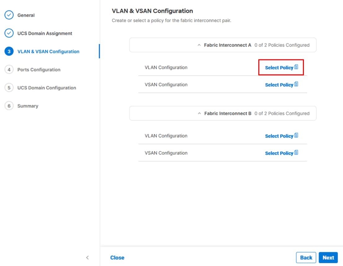
Step 2. In the pane on the right, click Create New.
Step 3. Verify the correct organization is selected from the drop-down list (for example, AA02) and provide a name for the policy (for example, AA02-6536-VLAN).
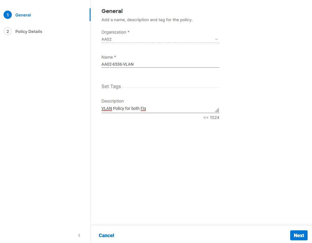
Step 4. Click Next.
Step 5. Click Add VLANs.
Step 6. Provide a name and VLAN ID for the native VLAN.
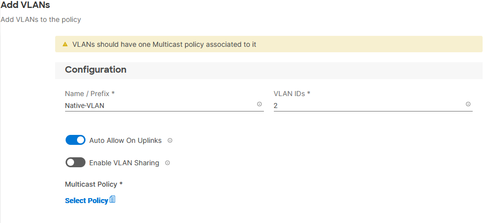
Step 7. Make sure Auto Allow On Uplinks is enabled.
Step 8. To create the required Multicast policy, click Select Policy under Multicast*.
Step 9. In the window on the right, Click Create New to create a new Multicast Policy.
Step 10. Provide a Name for the Multicast Policy (for example, AA02-MCAST).
Step 11. Provide optional Description and click Next.
Step 12. Leave the Snooping State selected and click Create.
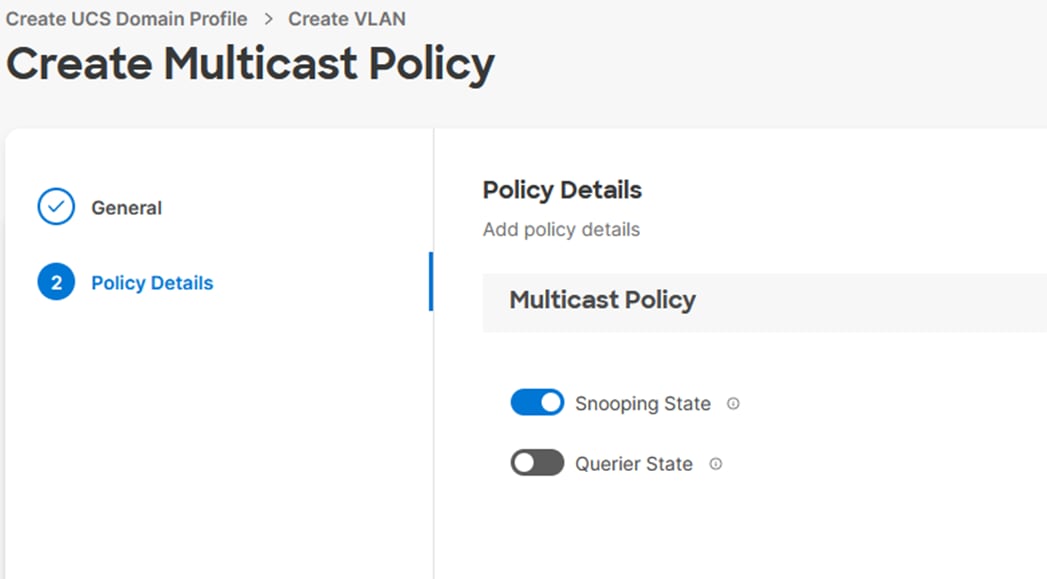
Step 13. Click Add to add the VLAN.
Step 14. Select Set Native VLAN ID and enter the VLAN number (for example, 2) under VLAN ID.
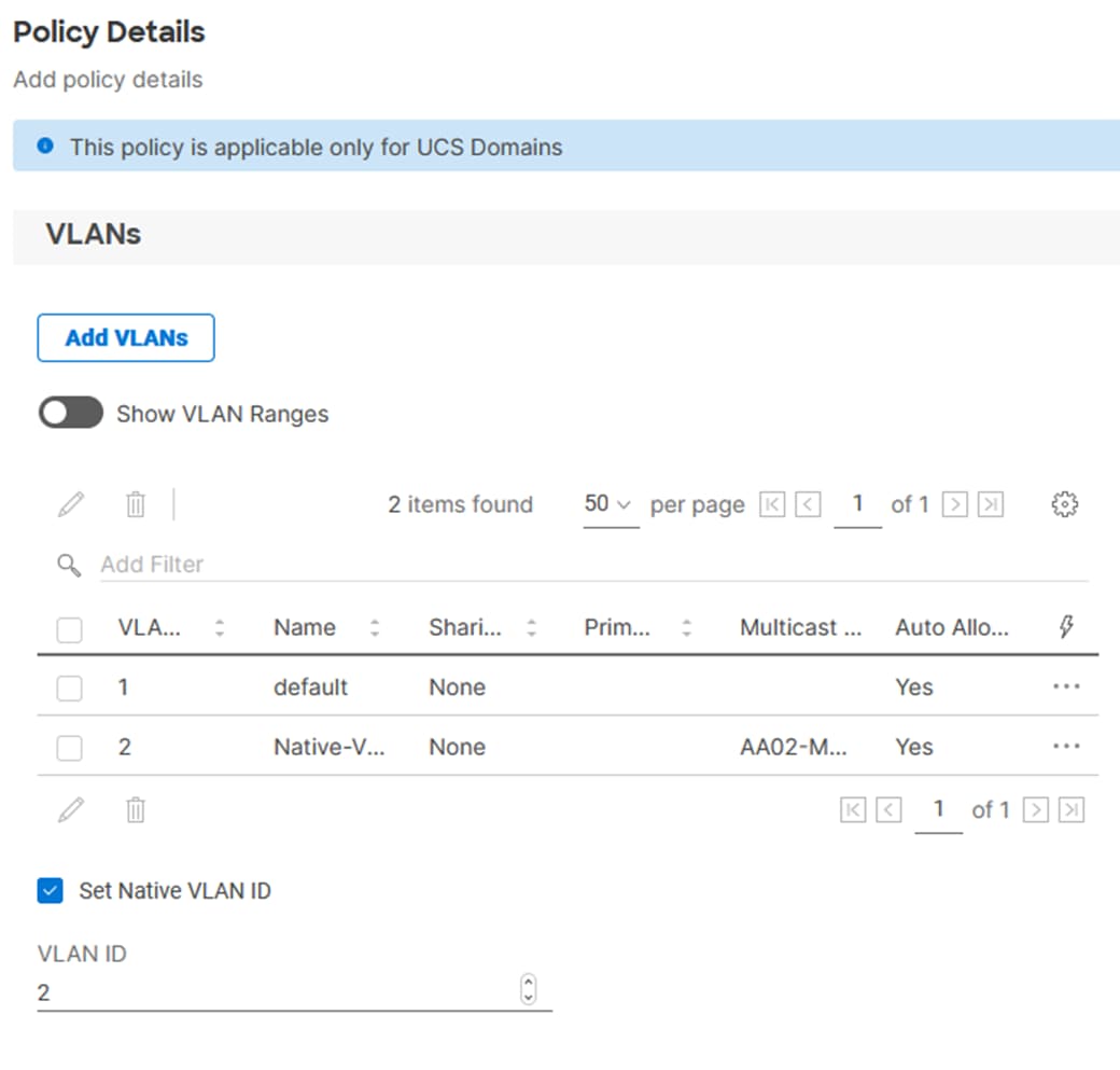
Step 15. Add the remaining VLANs for FlexPod by clicking Add VLANs and entering the VLANs one by one. Reuse the previously created multicast policy for all the VLANs.
The VLANs created during this validation are shown below:
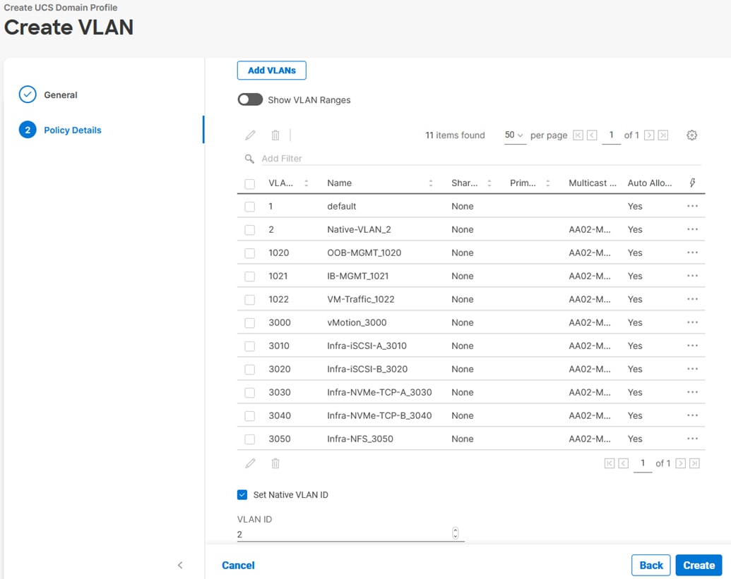
Note: The iSCSI and NVMe-TCP VLANs shown in the screen image above are only needed when iSCSI and NVME-TCP are configured in the environment.
Step 16. Click Create at bottom right to finish creating the VLAN policy and associated VLANs.
Step 17. Click Select Policy next to VLAN Configuration for Fabric Interconnect B and select the same VLAN policy.
Procedure 2. Create and Apply VSAN Policy (FC configuration only)
Step 1. Click Select Policy next to VSAN Configuration under Fabric Interconnect A. Then, in the pane on the right, click Create New.
Step 2. Verify the correct organization is selected from the drop-down list (for example, AA02) and provide a name for the policy (for example, AA02-6536-VSAN-Pol-A).
Note: A separate VSAN-Policy is created for each fabric interconnect.
Step 3. Click Next.
Step 4. Optionally enable Uplink Trunking.
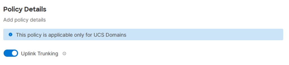
Step 5. Click Add VSAN and provide a name (for example, VSAN-A), VSAN ID (for example, 101), and associated Fibre Channel over Ethernet (FCoE) VLAN ID (for example, 101) for SAN A.
Step 6. Set VLAN Scope as Uplink.
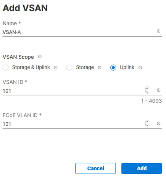
Step 7. Click Add.
Step 8. Click Create to finish creating VSAN policy for fabric A.
Step 9. Repeat the same steps to create a new VSAN policy for SAN-B. Name the policy to identify the SAN-B configuration (for example, AA02-6536-VSAN-Pol-B) and use appropriate VSAN and FCoE VLAN (for example, 102).
Step 10. Verify that a common VLAN policy and two unique VSAN policies are associated with the two fabric interconnects.
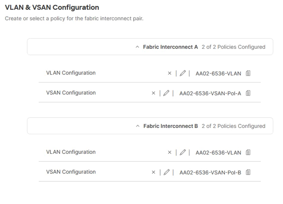
Step 11. Click Next.
Procedure 3. Ports Configuration
Step 1. Click Select Policy for Fabric Interconnect A.
Step 2. Click Create New in the pane on the right to define a new port configuration policy.
Note: Use two separate port policies for the fabric interconnects. Using separate policies provide flexibility when port configuration (port numbers or speed) differs between the two FIs. When configuring Fibre Channel, two port policies are required because each fabric interconnect uses a unique Fibre Channel VSAN ID.
Step 3. Verify correct organization is selected from the drop-down list (for example, AA02) and provide a name for the policy (for example, AA02-6536-PortPol-A). Select the UCS-FI-6536 Switch Model.
Step 4. Click Next.
Step 5. Move the slider to set up unified ports. In this deployment, the last two ports were selected as Fibre Channel ports as 4x32G breakouts. Click Next.
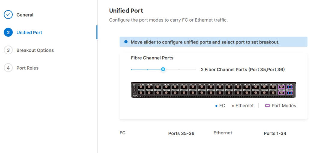
Step 6. If any Ethernet ports need to be configured as breakouts, either 4x25G or 4x10G, for connecting C-Series servers or a UCS 5108 chassis, configure them here. In the list, select the checkbox next to any ports that need to be configured as breakout or select the ports on the graphic. When all ports are selected, click Configure at the top of the window.
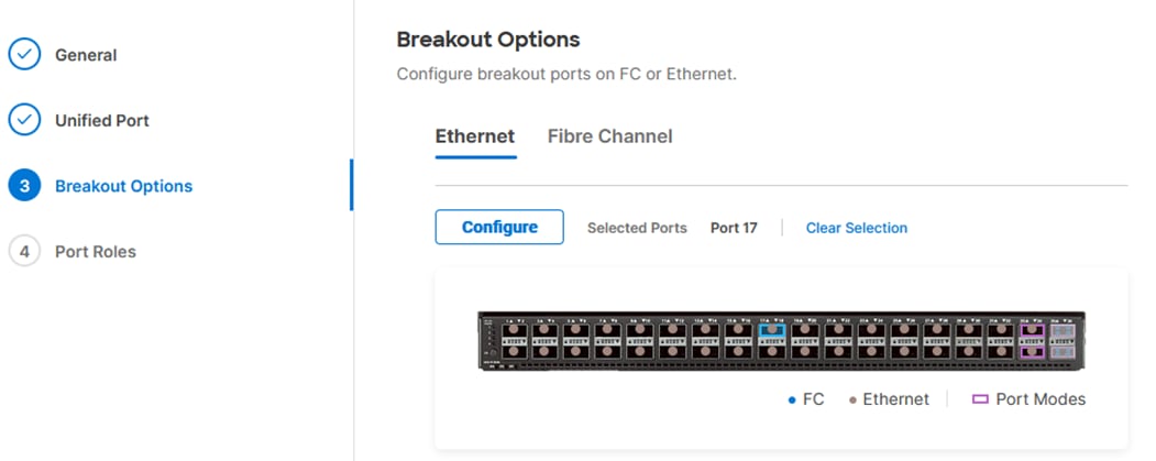
Step 7. In the Set Breakout popup, select either 4x10G or 4x25G and click Set.
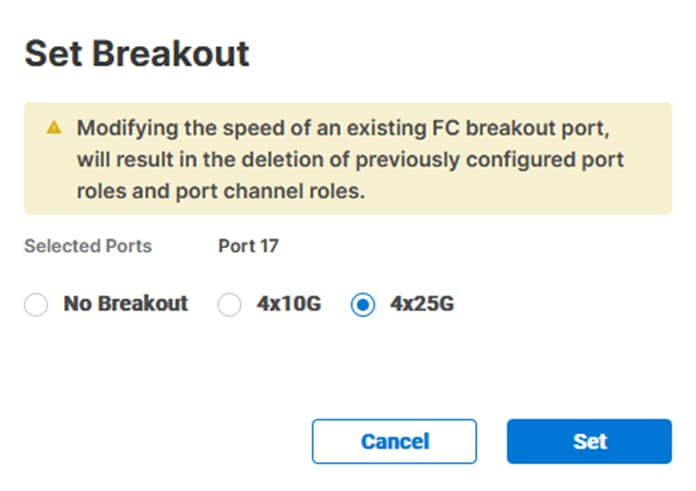
Step 8. Under Breakout Options, select Fibre Channel. Select any ports that need the speed changed from 16G to 32G and click Configure.
Step 9. In the Set Breakout popup, select 4x32G and click Set.
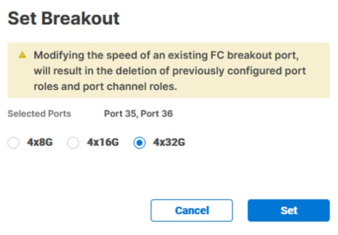
Step 10. Click Next.
Step 11. In the list, select the checkbox next to any ports that need to be configured as server ports, including ports connected to chassis or C-Series servers. Ports can also be selected on the graphic. When all ports are selected, click Configure. Breakout and non-breakout ports cannot be configured together. If you need to configure breakout and non-breakout ports, do this configuration in two steps.
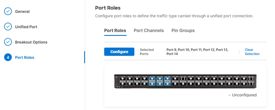
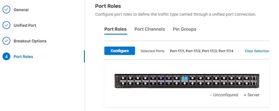
Step 12. From the drop-down list, select Server as the role. Also, unless you are using a Cisco Nexus 93180YC-FX3 as a FEX, leave Auto Negotiation enabled. If you need to do manual number of chassis or C-Series servers, enable Manual Chassis/Server Numbering.
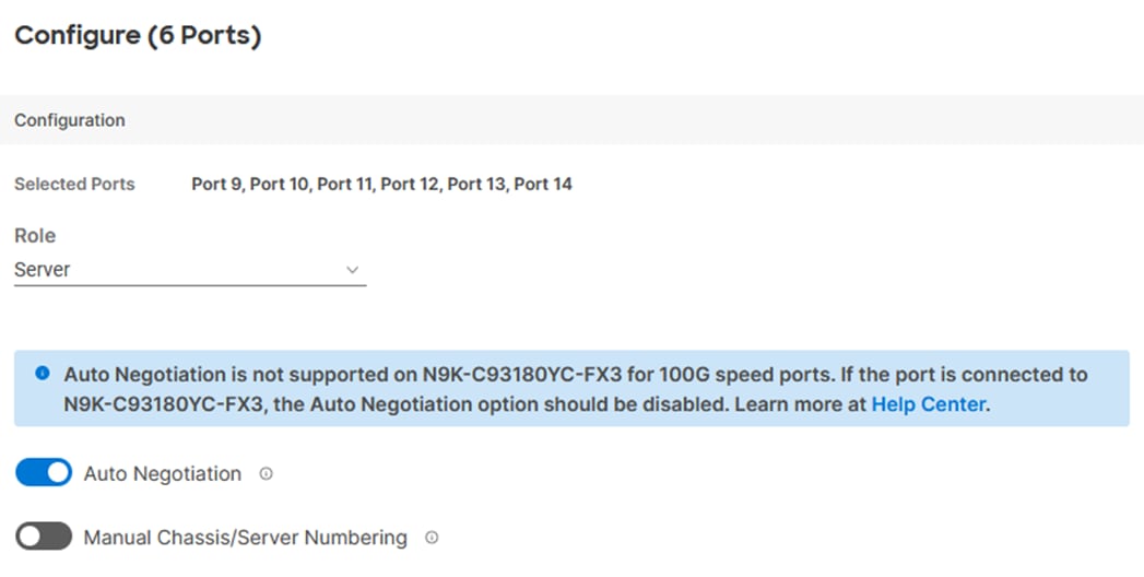
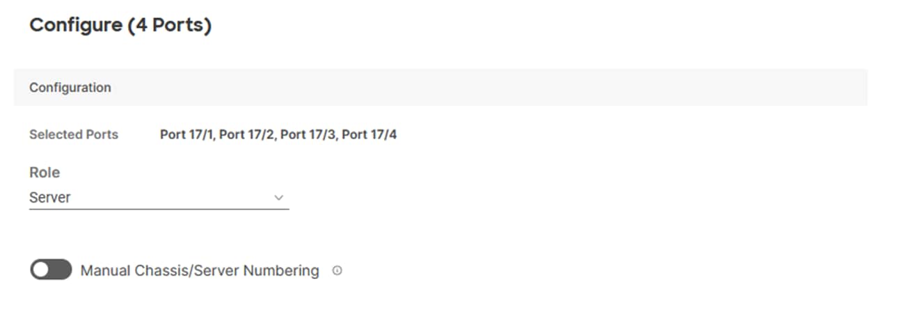
Step 13. Click Save.
Step 14. Configure the Ethernet uplink port channel by selecting Port Channel in the main pane and then clicking Create Port Channel.
Step 15. Select Ethernet Uplink Port Channel as the role, provide a port-channel ID (for example, 11), and select a value for Admin Speed from drop-down list (for example, Auto).
Note: You can create the Ethernet Network Group, Flow Control, Link Aggregation for defining disjoint Layer-2 domain or fine tune port-channel parameters. These policies were not used in this deployment and system default values were utilized.
Step 16. Under Link Control, click Select Policy. In the upper right, click Create New.
Step 17. Verify the correct organization is selected from the drop-down list (for example, AA02) and provide a name for the policy (for example, AA02-UDLD-Link-Control). Click Next.
Step 18. Leave the default values selected and click Create.
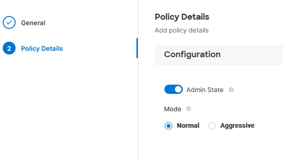
Step 19. Scroll down and select uplink ports from the list of available ports (for example, port 31 and 32)
Step 20. Click Save.
Procedure 4. Configure FC Port Channel (FC configuration only)
Note: An FC uplink port channels only needed when configuring FC SAN and can be skipped for IP-only (iSCSI) storage access.
Step 1. Configure a Fibre Channel Port Channel by selecting the Port Channel in the main pane again and clicking Create Port Channel.
Step 2. In the drop-down list under Role, select FC Uplink Port Channel.
Step 3. Provide a port-channel ID (for example, 135), select a value for Admin Speed (for example, 32Gbps), and provide a VSAN ID (for example, 101).
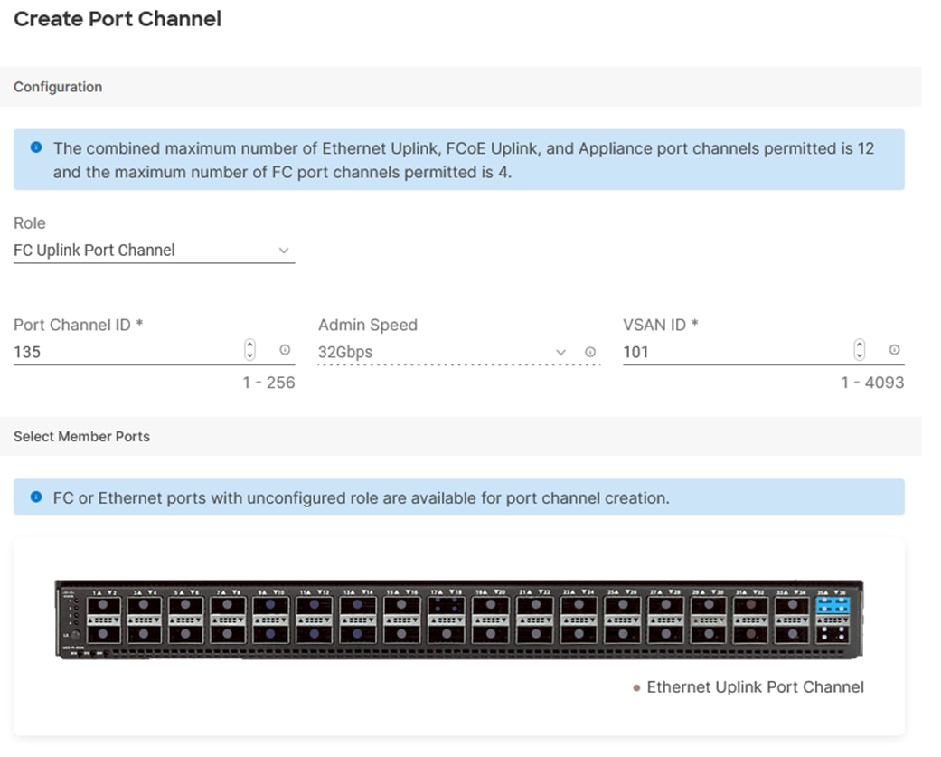
Step 4. Select ports (for example, 35/1,35/2,35/3,35/4).
Step 5. Click Save.
Step 6. Verify the port-channel IDs and ports after both the Ethernet uplink port channel and the Fibre Channel uplink port channel have been created.
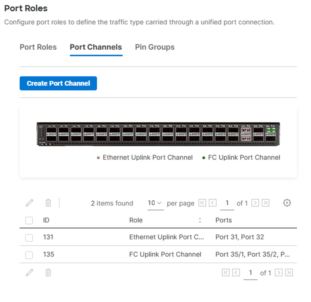
Step 7. Click Save to create the port policy for Fabric Interconnect A.
Note: Use the summary screen to verify that the ports were selected and configured correctly.
Procedure 5. Port Configuration for Fabric Interconnect B
Step 1. Repeat the steps in Ports Configuration and Configure FC Port Channel to create the port policy for Fabric Interconnect B including the Ethernet port-channel and the FC port-channel (if configuring SAN). Use the following values for various parameters:
● Name of the port policy: AA02-PortPol-B
● Ethernet port-Channel ID: 132
● FC port-channel ID: 135
● FC VSAN ID: 102
Step 2. When the port configuration for both fabric interconnects is complete and looks good, click Next.
Procedure 6. UCS Domain Configuration
Under UCS domain configuration, additional policies can be configured to setup NTP, Syslog, DNS settings, SNMP, QoS and UCS operating mode (end host or switch mode). For this deployment, four policies (NTP, Network Connectivity, SNMP, and System QoS) will be configured, as shown below:
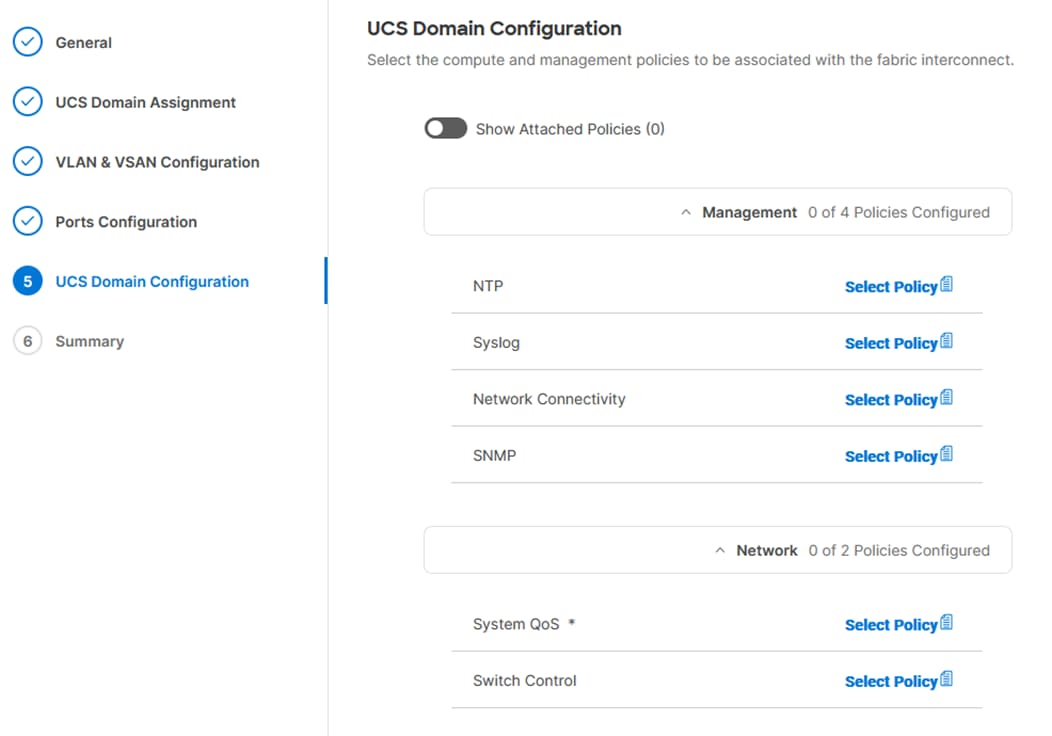
Procedure 7. Configure NTP Policy
Step 1. Click Select Policy next to NTP and then, in the pane on the right, click Create New.
Step 2. Verify correct organization is selected from the drop-down list (for example, AA02) and provide a name for the policy (for example, AA02-NTP).
Step 3. Click Next.
Step 4. Enable NTP, provide the first NTP server IP address, and select the time zone from the drop-down list.
Step 5. Add a second NTP server by clicking + next to the first NTP server IP address.
Note: The NTP server IP addresses should be Nexus switch management IPs. NTP distribution was configured in the Cisco Nexus switches.
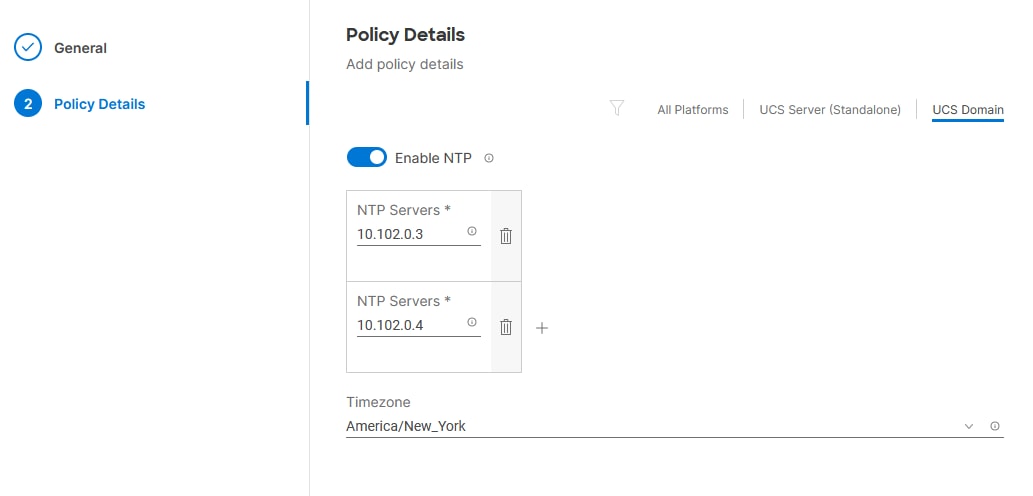
Step 6. Click Create.
Procedure 8. Configure Network Connectivity Policy
Step 1. Click Select Policy next to Network Connectivity and then, in the pane on the right, click Create New.
Step 2. Verify correct organization is selected from the drop-down list (for example, AA02) and provide a name for the policy (for example, AA02-NetConn).
Step 3. Click Next.
Step 4. Provide DNS server IP addresses for Cisco UCS (for example, 10.102.1.151 and 10.102.1.152).
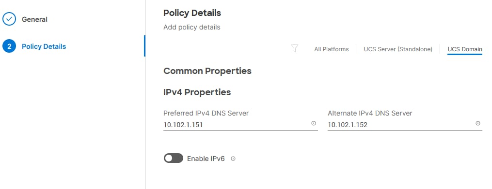
Step 5. Click Create.
Procedure 9. Configure SNMP Policy
Step 1. Click Select Policy next to SNMP and then, in the pane on the right, click Create New.
Step 2. Verify correct organization is selected from the drop-down list (for example, AA02) and provide a name for the policy (for example, AA02-SNMP).
Step 3. Click Next.
Step 4. Provide a System Contact email address, a System Location, and optional Community Strings.
Step 5. Under SNMP Users, click Add SNMP User.
Step 6. This user id will be used for Cisco DCNM SAN to query the UCS Fabric Interconnects. Fill in a user name (for example, snmpadmin), Auth Type SHA, an Auth Password with confirmation, Privacy Type AES, and a Privacy Password with confirmation. Click Add.
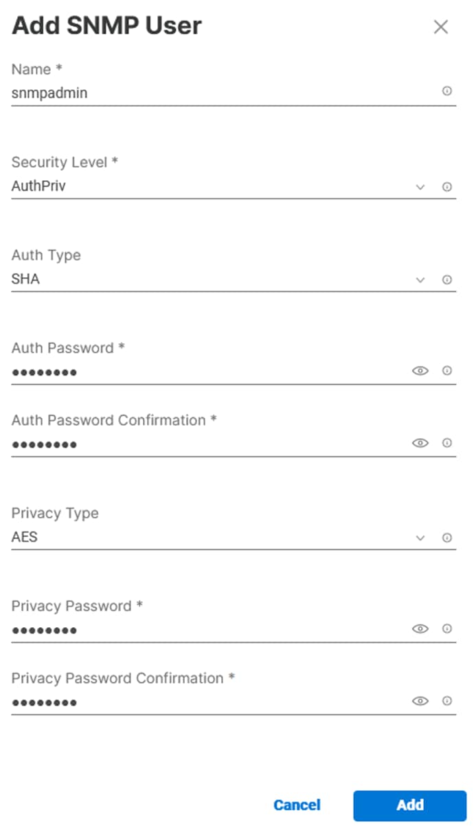
Step 7. Optionally, add an SNMP Trap Destination (for example, the DCNM SAN IP Address). If the SNMP Trap Destination is V2, you must add Trap Community String.
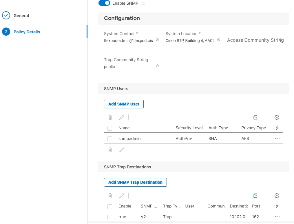
Step 8. Click Create.
Procedure 10. Configure System QoS Policy
Step 1. Click Select Policy next to System QoS* and in the pane on the right, click Create New.
Step 2. Verify correct organization is selected from the drop-down list (for example, AA02) and provide a name for the policy (for example, AA02-QoS).
Step 3. Click Next.
Step 4. Change the MTU for Best Effort class to 9216.
Step 5. Keep the default selections or change the parameters if necessary.
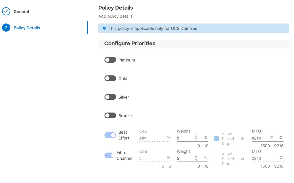
Step 6. Click Create.
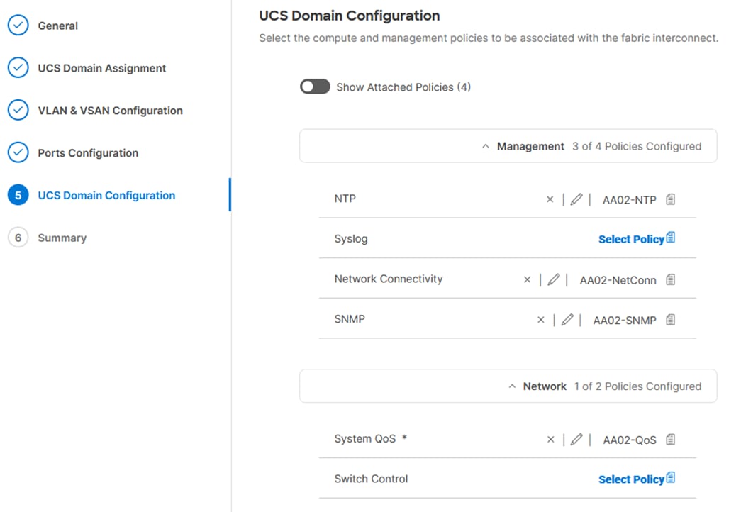
Step 7. Click Next.
Step 1. Verify all the settings including the fabric interconnect settings, by expanding the settings and make sure that the configuration is correct.
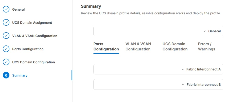
Procedure 12. Deploy the Cisco UCS Domain Profile
Step 1. From the UCS domain profile Summary view, Click Deploy.
Step 2. Acknowledge any warnings and click Deploy again.
Note: The system will take some time to validate and configure the settings on the fabric interconnects. Log into the console servers to see when the Cisco UCS fabric interconnects have finished configuration and are successfully rebooted.
Procedure 13. Verify Cisco UCS Domain Profile Deployment
When the Cisco UCS domain profile has been successfully deployed, the Cisco UCS chassis and the blades should be successfully discovered.
Note: It takes a while to discover the blades for the first time. Watch the number of outstanding requests in Cisco Intersight:
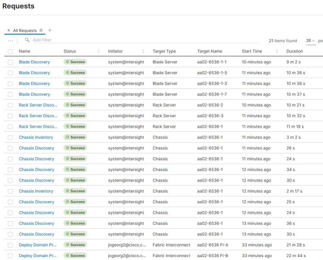
Step 1. Log into Cisco Intersight. Under Infrastructure Service > Configure > Profiles > UCS Domain Profiles, verify that the domain profile has been successfully deployed.
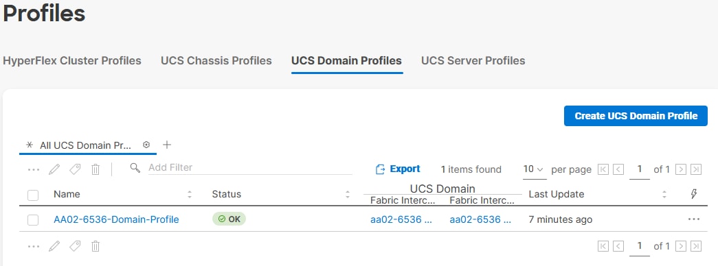
Step 2. Verify that the chassis (either UCSX-9508 or UCS 5108 chassis) has been discovered and is visible under Infrastructure Service > Operate > Chassis.
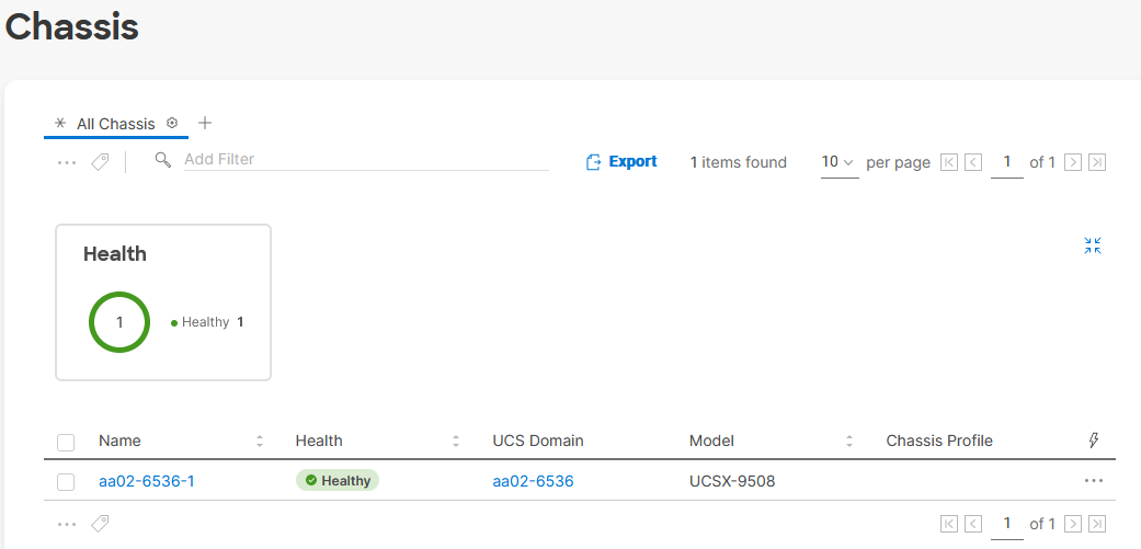
Step 3. Verify that the servers have been successfully discovered and are visible under Infrastructure Service > Operate > Servers.
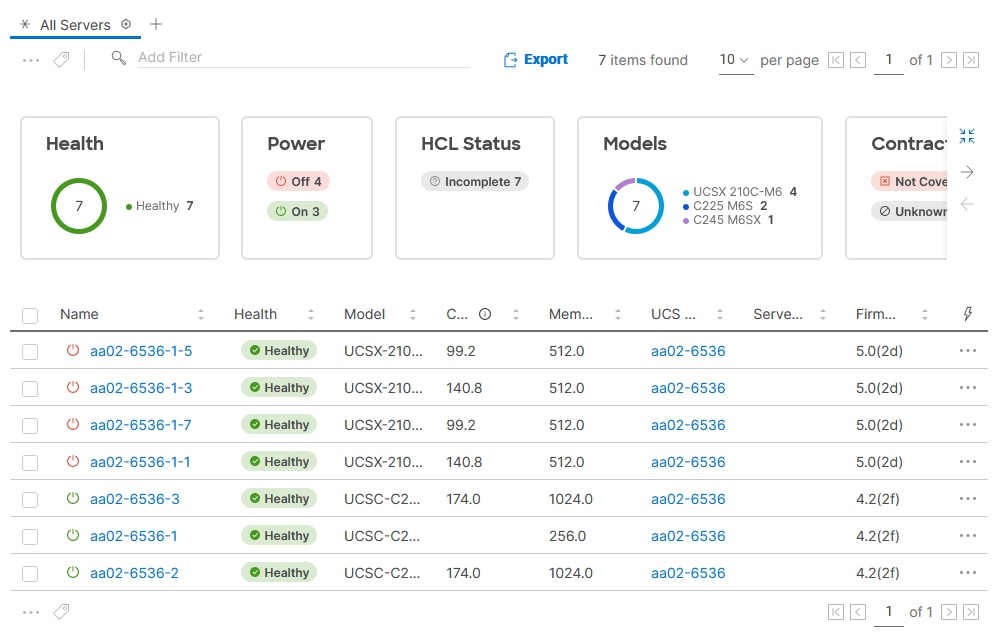
Cisco UCS IMM Manual Configuration
Configure Cisco UCS Chassis Profile (Optional)
The Cisco UCS Chassis profile in Cisco Intersight allows you to configure various parameters for chassis, including:
● IMC Access Policy: IP configuration for the in-band chassis connectivity. This setting is independent of Server IP connectivity and only applies to communication to and from chassis.
● SNMP Policy, and SNMP trap settings.
● Power Policy to enable power management and power supply redundancy mode.
● Thermal Policy to control the speed of FANs
A chassis policy can be assigned to any number of chassis profiles to provide a configuration baseline for a chassis. In this deployment, no chassis profile was created or attached to the chassis, but you can configure policies to configure SNMP or Power parameters and attach them to the chassis.
Configure Server Profile Template
In the Cisco Intersight platform, a server profile enables resource management by simplifying policy alignment and server configuration. The server profiles are derived from a server profile template. A Server profile template and its associated policies can be created using the server profile template wizard. After creating server the profile template, customers can derive multiple consistent server profiles from the template.
The server profile templates captured in this deployment guide supports Cisco UCS X210c M6 and B200M6 compute nodes with 5th Generation and 4th Generation VICs, and Cisco UCS C245 and C225 compute nodes with 4th Generation VICs.
vNIC and vHBA Placement for Server Profile Template
In this deployment, separate server profile templates are created for iSCSI connected storage and for FC connected storage. The vNIC and vHBA layout is covered below. While most of the policies are common across various templates, the LAN connectivity and SAN connectivity policies are unique and will use the information in the tables below.
Six vNICs are configured to support iSCSI boot from SAN. These vNICs are manually placed as listed in Table 6.
Note: NVMe-TCP VLAN Interfaces can be added to the iSCSI vNICs when NVMe-TCP is being used.
Table 6. vNIC placement for iSCSI connected storage
| vNIC/vHBA Name |
Switch ID |
PCI Order |
| 00-vSwitch0-A |
A |
0 |
| 01-vSwitch0-B |
B |
1 |
| 02-VDS0-A |
A |
2 |
| 03-VDS0-B |
B |
3 |
| 04-ISCSI-A |
A |
4 |
| 05-ISCSI-B |
B |
5 |
Four vNICs and four vHBAs are configured to support FC boot from SAN. Two vHBAs (FCP-Fabric-A and FCP-Fabric-B) are used for boot from SAN connectivity and the remaining two vHBAs (FC-NVMe-Fabric-A and FC-NVMe-Fabric-B) are used to support NVMe-o-FC when FC-NVMe is being used. These devices are manually placed as listed in Table 7.
Table 7. vHBA and vNIC placement for FC connected storage
| vNIC/vHBA Name |
Switch ID |
PCI Order |
| FCP-Fabric-A |
A |
4 |
| FCP-Fabric-B |
B |
5 |
| FC-NVMe-Fabric-A* |
A |
6 |
| FC-NVMe-Fabric-B* |
B |
7 |
| 00-vSwitch0-A |
A |
0 |
| 01-vSwitch0-B |
B |
1 |
| 02-VDS0-A |
A |
2 |
| 03-VDS0-B |
B |
3 |
Procedure 1. Server Profile Template Creation
Step 1. Log into the Cisco Intersight.
Step 2. Go to Infrastructure Service > Configure > Templates and in the main window click Create UCS Server Profile Template.
Procedure 2. General Configuration
Step 1. Select the organization from the drop-down list (for example, AA02).
Step 2. Provide a name for the server profile template. The names used in this part of the deployment are:
● Intel-5G-VIC-ISCSI-Boot-Template (iSCSI boot from SAN with or without NVMe-TCP)
● Intel-5G-VIC-FC-Boot-Template (FC boot from SAN with or without FC-NVMe)
Step 3. Select UCS Server (FI-Attached).
Step 4. Provide an optional description.
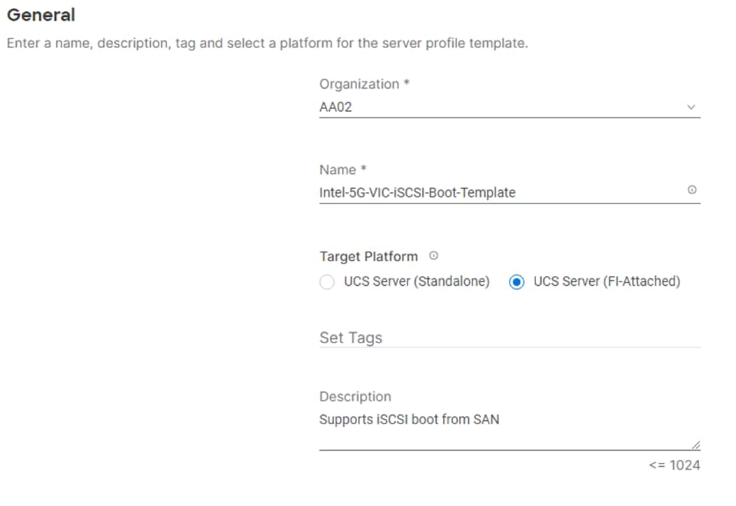
Step 5. Click Next.
Procedure 3. Compute Configuration – Configure UUID Pool
Step 1. Click Select Pool under UUID Pool and then in the pane on the right, click Create New.
Step 2. Verify correct organization is selected from the drop-down list (for example, AA02) and provide a name for the UUID Pool (for example, AA02-UUID-Pool).
Step 3. Provide an optional Description and click Next.
Step 4. Provide a UUID Prefix (for example, a prefix of AA020000-0000-0001 was used).
Step 5. Add a UUID block.
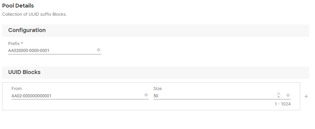
Step 6. Click Create.
Procedure 4. Configure BIOS Policy
Step 1. Click Select Policy next to BIOS and in the pane on the right, click Create New.
Step 2. Verify correct organization is selected from the drop-down list (for example, AA02) and provide a name for the policy (for example, AA02-Intel-M6-Virt-BIOS).
Step 3. Click Next.
Step 4. On the Policy Details screen, select appropriate values for the BIOS settings. In this deployment, the BIOS values were selected based on recommendations in the performance tuning guide for Cisco UCS M6 BIOS: https://www.cisco.com/c/en/us/products/collateral/servers-unified-computing/ucs-b-series-blade-servers/performance-tuning-guide-ucs-m6-servers.html. Set the parameters below and leave all other parameters set to “platform-default.”
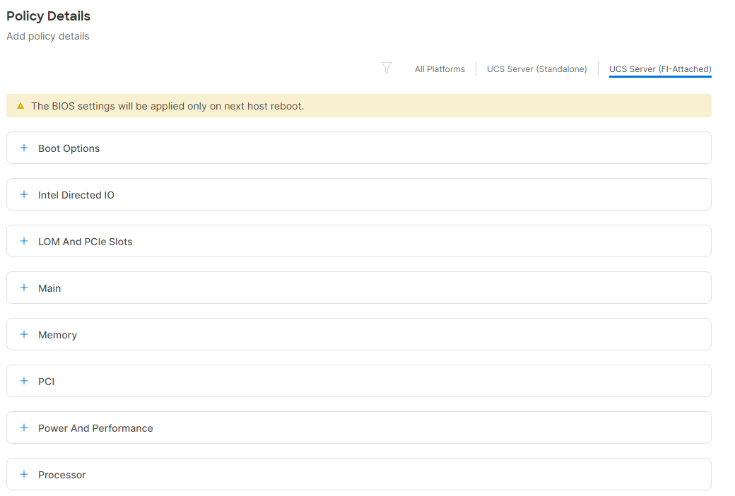
● Memory > NVM Performance Setting: Balanced Profile
● Power and Performance > Enhanced CPU Performance: Auto
● Processor > Energy Efficient Turbo: enabled
● Processor > Processor C1E: enabled
● Processor > Processor C6 Report: enabled
● Server Management > Consistent Device Naming: enabled
Step 5. Click Create.
Step 6. As an alternative, if you have M5 servers, create a BIOS policy named AA02-Intel-M5-Virt-BIOS with the following parameters:
● Memory > NVM Performance Setting: Balanced Profile
● Processor > Power Technology: custom
● Processor > Processor C1E: disabled
● Processor > Processor C3 Report: disabled
● Processor > Processor C6 Report: disabled
● Processor > CPU C State: disabled
● Server Management > Consistent Device Naming: enabled
Note: These parameters were derived from Performance Tuning Guide for Cisco UCS M5 Servers White Paper.
Step 7. A final alternative, if you have AMD-based UCS C225 or C245 servers, create a BIOS policy named AA02-AMD-M6-Virt-BIOS with the following parameters:
● Memory > NUMA Nodes per Socket: NPS4
● Processor > APBDIS: 1
● Processor > Fixed SOC P-State: P0
● Processor > ACPI SRAT L3 Cache As NUMA Domain: enabled
● Server Management > Consistent Device Naming: enabled
Note: These parameters were derived from Performance Tuning for Cisco UCS C225 M6 and C245 M6 Rack Servers with 3rd Gen AMD EPYC Processors White Paper.
Procedure 5. Configure Boot Order Policy for iSCSI Hosts
Note: The FC boot order policy is different from iSCSI boot policy and is explained next.
Step 1. Click Select Policy next to Boot Order and then, in the pane on the right, click Create New.
Step 2. Verify correct organization is selected from the drop-down list (for example, AA02) and provide a name for the policy (for example, AA02-iSCSI-Boot-Order).
Step 3. Click Next.
Step 4. For Configured Boot Mode, select Unified Extensible Firmware Interface (UEFI).
Step 5. Turn on Enable Secure Boot.
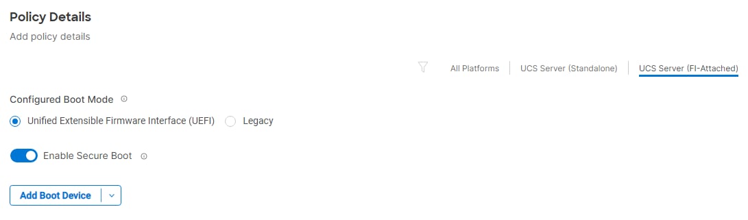
Step 6. Click Add Boot Device drop-down list and select Virtual Media.
Step 7. Provide a device name (for example, KVM-Mapped-ISO) and then, for the subtype, select KVM Mapped DVD.
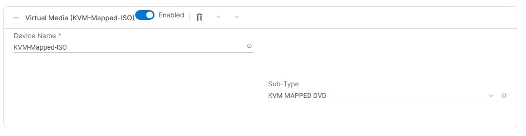
Step 8. From the Add Boot Device drop-down list, select iSCSI Boot.
Step 9. Provide the Device Name: iSCSI-A-Boot and the exact name of the interface used for iSCSI boot under Interface Name: 04-iSCSI-A.
Note: The device names (iSCSI-A-Boot and iSCSI-B-Boot) are being defined here and will be used in the later steps of the iSCSI configuration.
Step 10. From the Add Boot Device drop-down list, select iSCSI Boot.
Step 11. Provide the Device Name: iSCSI-B-Boot and the exact name of the interface used for iSCSI boot under Interface Name: 05-iSCSI-B.
Step 12. From the Add Boot Device drop-down list, select Virtual Media.
Step 13. Add Device Name CIMC-Mapped-ISO and select the subtype CIMC MAPPED DVD.
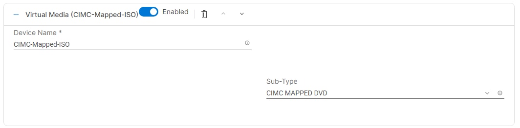
Step 14. Verify the order of the boot policies and adjust the boot order as necessary using arrows next to the Delete button.
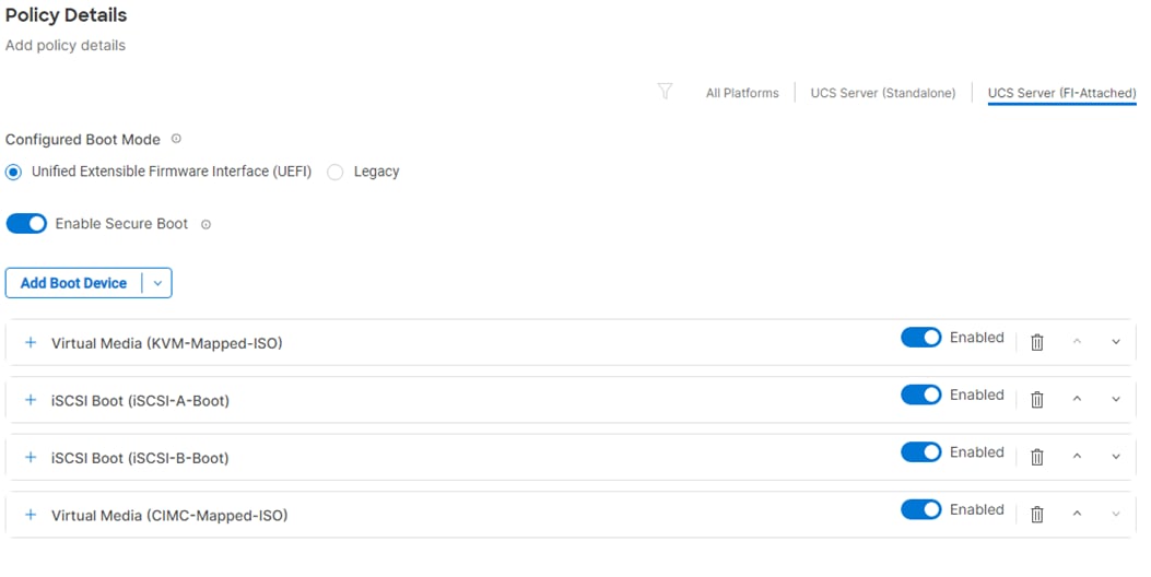
Step 15. Click Create.
Procedure 6. Configure Boot Order Policy for FC Hosts
Note: The FC boot order policy applies to all FC hosts including hosts that support FC-NVMe storage access.
Step 1. Click Select Policy next to Boot Order and then, in the pane on the right, click Create New.
Step 2. Verify correct organization is selected from the drop-down list (for example, AA02) and provide a name for the policy (for example, AA02-FC-Boot-Order).
Step 3. Click Next.
Step 4. For Configured Boot Mode, select Unified Extensible Firmware Interface (UEFI).
Step 5. Turn on Enable Secure Boot.
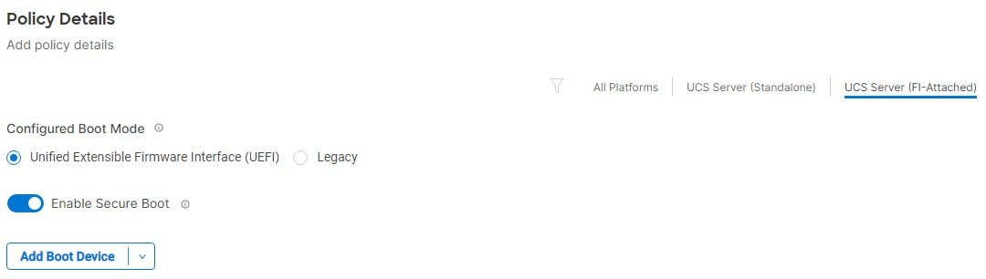
Step 6. Click Add Boot Device drop-down list and select Virtual Media.
Step 7. Provide a device name (for example, KVM-Mapped-ISO) and then, for the subtype, select KVM Mapped DVD.
For Fibre Channel SAN boot, all four NetApp controller FCP LIFs will be added as boot options. The four LIFs are named as follows:
● fcp-lif-01a: NetApp Controller 1, LIF for Fibre Channel SAN A
● fcp-lif-01b: NetApp Controller 1, LIF for Fibre Channel SAN B
● fcp-lif-02a: NetApp Controller 2, LIF for Fibre Channel SAN A
● fcp-lif-02b: NetApp Controller 2, LIF for Fibre Channel SAN B
Step 8. From the Add Boot Device drop-down list, select SAN Boot.
Step 9. Provide the Device Name: fcp-lif-01a and the Logical Unit Number (LUN) value (for example, 0).
Step 10. Provide an interface name FCP-Fabric-A. This value is important and should match the vHBA name.
Note: FCP-Fabric-A is used to access fcp-lif-01a and fcp-lif-02a and FCP-Fabric-B is used to access fcp-lif-01b and fcp-lif-02b.
Step 11. Add the appropriate World Wide Port Name (WWPN) as the Target WWPN.
Note: To obtain the WWPN values, log into NetApp controller using SSH and enter the following command: network interface show -vserver <svm-name> -data-protocol fcp.
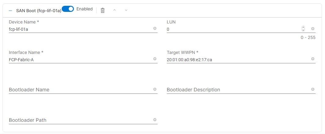
Step 12. Repeat steps 8-11 three more times to add all the NetApp LIFs.
Step 13. From the Add Boot Device drop-down list, select Virtual Media.
Step 14. Add Device Name CIMC-Mapped-ISO and select the subtype CIMC MAPPED DVD.
Step 15. Verify the order of the boot policies and adjust the boot order as necessary using arrows next to the Delete button.
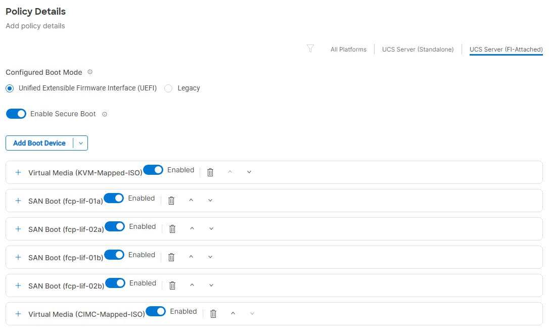
Step 16. Click Create.
Step 17. Make sure the correct Boot Order policy is selected. If not, select the correct policy.
Procedure 7. Configure Virtual Media Policy
Step 1. Click Select Policy next to Virtual Media and then, in the pane on the right, click Create New.
Step 2. Verify correct organization is selected from the drop-down list (for example, AA02) and provide a name for the policy (for example, AA02-KVM-Mount-Media).
Step 3. Turn on Enable Virtual Media, Enable Virtual Media Encryption, and Enable Low Power USB.
Step 4. Do not Add Virtual Media at this time, but the policy can be modified and used to map and ISO for a CIMC Mapped DVD.
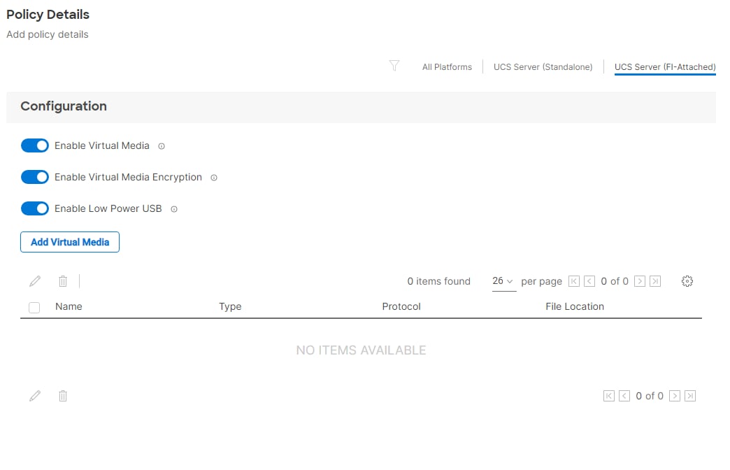
Step 5. Click Create.
Step 6. Click Next to move to Management Configuration.
Four policies will be added to the management configuration:
● IMC Access to define the pool of IP addresses for compute node KVM access
● IPMI Over LAN to allow Intersight to manage IPMI messages
● Local User to provide local administrator to access KVM
● Virtual KVM to allow the Tunneled KVM
Procedure 1. Configure Cisco IMC Access Policy
Step 1. Click Select Policy next to IMC Access and then, in the pane on the right, click Create New.
Step 2. Verify correct organization is selected from the drop-down list (for example, AA02) and provide a name for the policy (for example, AA02-IMC-Access-Policy).
Step 3. Click Next.
Note: You can select in-band management access to the compute node using an in-band management VLAN (for example, VLAN 1021) or out-of-band management access via the Mgmt0 interfaces of the FIs. KVM Policies like SNMP, vMedia and Syslog are currently not supported via Out-Of-Band and will require an In-Band IP to be configured.
Step 4. Click UCS Server (FI-Attached).
Step 5. Enable In-Band Configuration. Enter the IB-MGMT VLAN ID (for example, 1021) and select “IPv4 address configuration.”
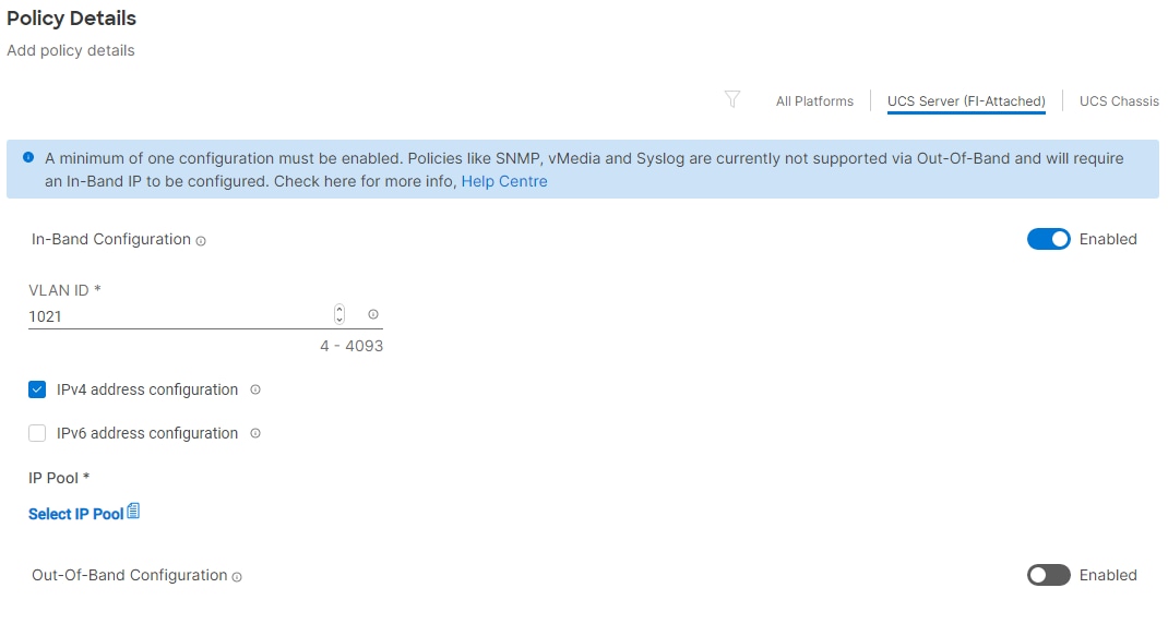
Step 6. Under IP Pool, click Select IP Pool and then, in the pane on the right, click Create New.
Step 7. Verify the correct organization is selected from the drop-down list (for example, AA02) and provide a name for the policy (for example, AA02-IB-MGMT-IP-Pool).
Step 8. Select Configure IPv4 Pool and provide the information to define a pool for KVM IP address assignment including an IP Block.
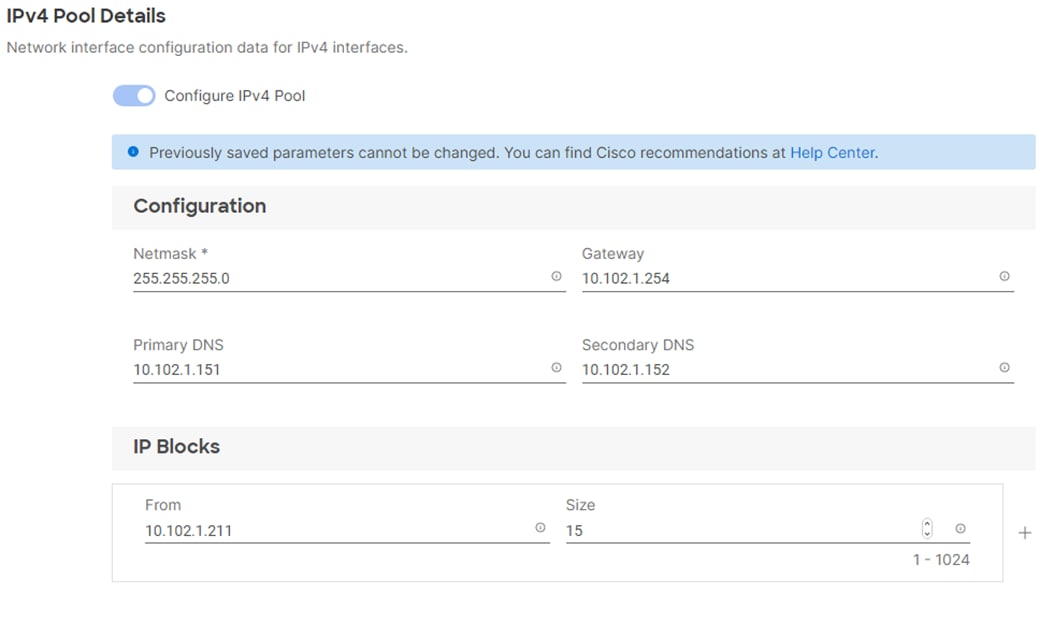
Note: The management IP pool subnet should be accessible from the host that is trying to open the KVM connection. In the example shown here, the hosts trying to open a KVM connection would need to be able to route to the 10.102.1.0/24 subnet.
Step 9. Click Next.
Step 10. Deselect Configure IPv6 Pool.
Step 11. Click Create to finish configuring the IP address pool.
Step 12. Click Create to finish configuring the IMC access policy.
Procedure 2. Configure IPMI Over LAN Policy
Step 1. Click Select Policy next to IPMI Over LAN and then, in the pane on the right, click Create New.
Step 2. Verify the correct organization is selected from the drop-down list (for example, AA02) and provide a name for the policy (for example, AA02-Enable-IPMIoLAN-Policy).
Step 3. On the right, select UCS Server (FI-Attached)
Step 4. Turn on Enable IPMI Over LAN.
Step 5. From the Privilege Level drop-down list, select admin.
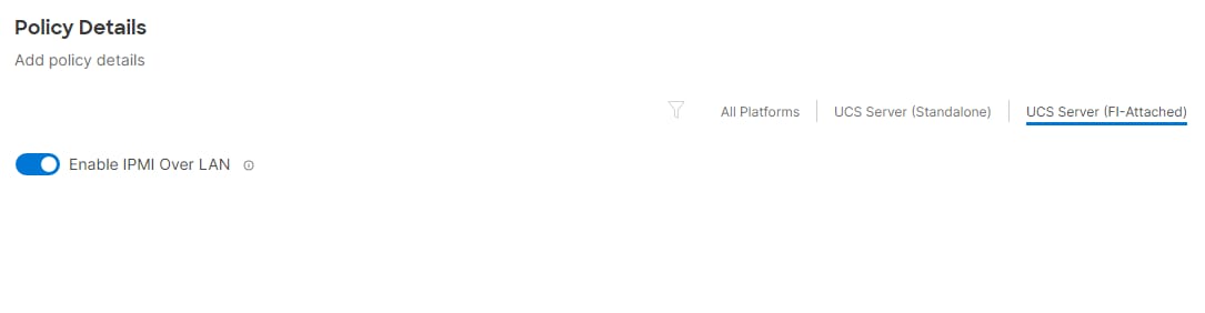
Step 6. Click Create.
Procedure 3. Configure Local User Policy
Step 1. Click Select Policy next to Local User and then, in the pane on the right, click Create New.
Step 2. Verify correct organization is selected from the drop-down list (for example, AA02) and provide a name for the policy (for example, AA02-LocalUser-Policy).
Step 3. Verify that UCS Server (FI-Attached) is selected.
Step 4. Verify that Enforce Strong Password is selected.
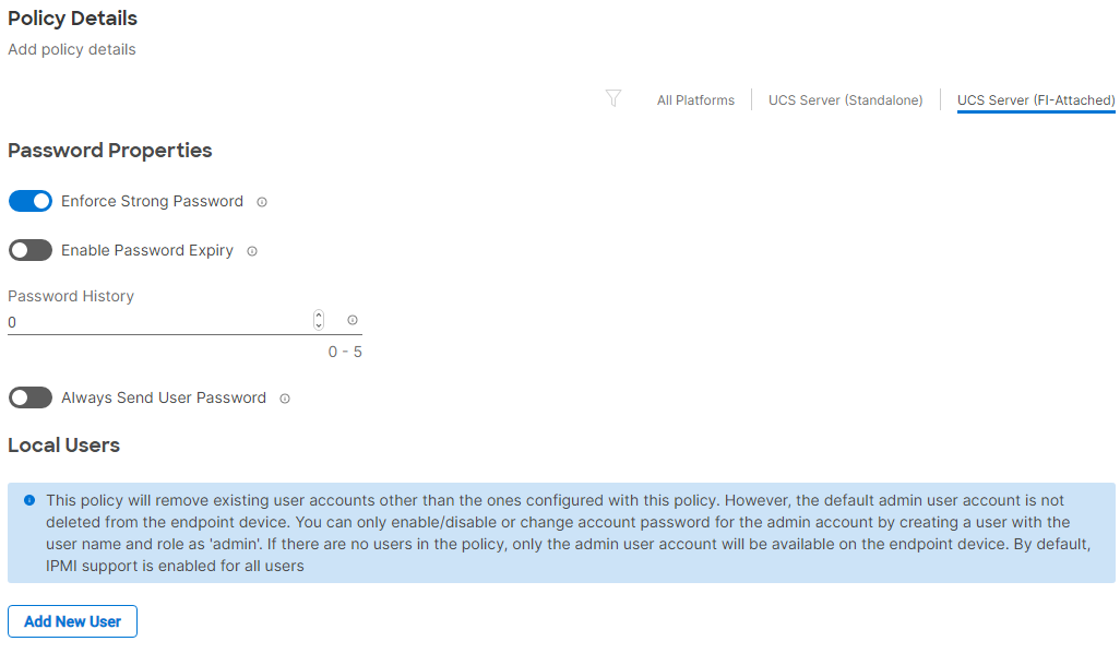
Step 5. Click Add New User and then click + next to the New User
Step 6. Provide the username (for example, flexadmin), select a role for example, admin), and provide a password.
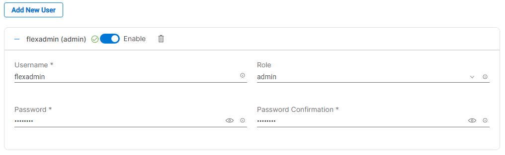
Note: The username and password combination defined here will be used as an alternate to log in to KVMs and can be used for IPMI.
Step 7. Click Create to finish configuring the user.
Step 8. Click Create to finish configuring local user policy.
Procedure 4. Configure Virtual KVM Policy
Step 1. Click Select Policy next to Virtual KVM and then, in the pane on the right, click Create New.
Step 2. Verify correct organization is selected from the drop-down list (for example, AA02) and provide a name for the policy (for example, AA02-KVM-Policy).
Step 3. Verify that UCS Server (FI-Attached) is selected.
Step 4. Turn on “Allow Tunneled vKVM.”
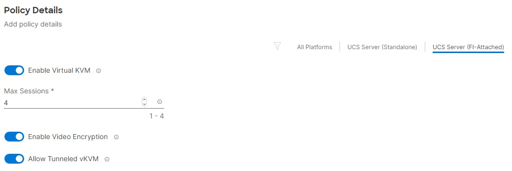
Step 5. Click Create.
Note: To fully enable Tunneled KVM, once the Server Profile Template has been created, go to System > Settings > Security and Privacy and click Configure. Turn on “Allow Tunneled vKVM Launch” and “Allow Tunneled vKVM Configuration.”
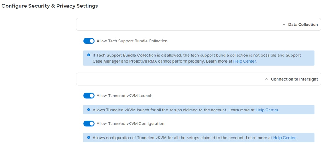
Step 6. Click Next to move to Storage Configuration.
Procedure 5. Storage Configuration
Step 1. Click Next on the Storage Configuration screen. No configuration is needed in the local storage system.
Procedure 6. Create Network Configuration - LAN Connectivity
The LAN connectivity policy defines the connections and network communication resources between the server and the LAN. This policy uses pools to assign MAC addresses to servers and to identify the vNICs that the servers use to communicate with the network. For iSCSI hosts, this policy also defined an IQN address pool.
For consistent vNIC and vHBA placement, manual vHBA/vNIC placement is utilized. Additionally, the assumption is being made here that each server contains only on VIC card and Simple placement, which adds vNICs to the first VIC, is being used. If you have more than one VIC in a server, the Advanced placement will need to be used. ISCSI boot from SAN hosts and FC boot from SAN hosts require different numbers of vNICs/vHBAs and different placement order therefore the iSCSI host and the FC host LAN connectivity policies are explained separately in this section. If only configuring FC-booted hosts, skip to Procedure 14.
The iSCSI boot from SAN hosts uses 6 vNICs configured as listed in Table 8.
Table 8. vNICs for iSCSI LAN Connectivity
| vNIC/vHBA Name |
Switch ID |
PCI Order |
VLANs |
| 00-vSwitch0-A |
A |
0 |
IB-MGMT, NFS |
| 01-vSwitch0-B |
B |
1 |
IB-MGMT, NFS |
| 02-vDS0-A |
A |
2 |
VM Traffic, vMotion |
| 03-vDS0-B |
B |
3 |
VM Traffic, vMotion |
| 04-ISCSI-A |
A |
4 |
iSCSI-A-VLAN |
| 05-ISCSI-B |
B |
5 |
iSCSI-B-VLAN |
Step 1. Click Select Policy next to LAN Connectivity and then, in the pane on the right, click Create New.
Step 2. Verify the correct organization is selected from the drop-down list (for example, AA02) and provide a name for the policy (for example, AA02-iSCSI-Boot-5G-LanCon-Pol). Select UCS Server (FI-Attached). Click Next.
Step 3. Under IQN, select Pool.
Step 4. Click Select Pool under IQN Pool and then, in the pane on the right, click Create New.
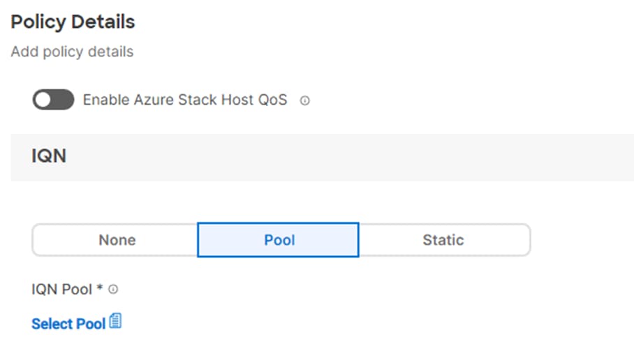
Step 5. Verify the correct organization is selected from the drop-down list (for example, AA02) and provide a name for the IQN Pool (for example, AA02-IQN Pool).
Step 6. Click Next.
Step 7. Provide the values for Prefix and IQN Block to create the IQN pool.
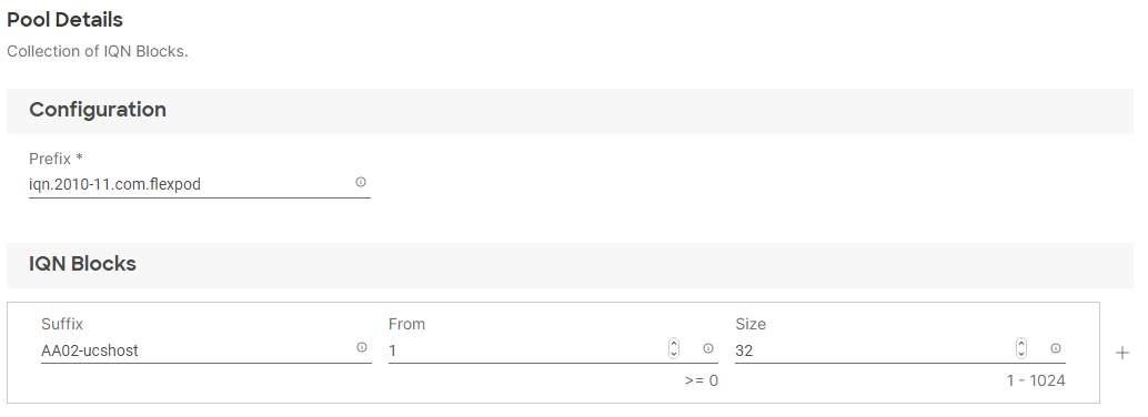
Step 8. Click Create.
Step 9. Under vNIC Configuration, select Manual vNICs Placement.
Step 10. Click Add vNIC.
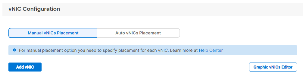
Procedure 7. Create MAC Address Pool for Fabric A and B
Note: When creating the first vNIC, the MAC address pool has not been defined yet therefore a new MAC address pool will need to be created. Two separate MAC address pools are configured for each Fabric. MAC-Pool-A will be reused for all Fabric-A vNICs, and MAC-Pool-B will be reused for all Fabric-B vNICs.
| Pool Name |
Starting MAC Address |
Size |
vNICs |
| MAC-Pool-A |
00:25:B5:A2:0A:00 |
256* |
01-vSwitch0-A, 03-VDS0-A, 05-ISCSI-A |
| MAC-Pool-B |
00:25:B5:A3:0B:00 |
256* |
02-vSwitch0-B, 04-VDS0-B, 06-ISCSI-B |
Note: Each server requires 3 MAC addresses from the pool. Adjust the size of the pool according to your requirements.
Step 1. Click Select Pool under MAC Address Pool and then, in the pane on the right, click Create New.
Step 2. Verify the correct organization is selected from the drop-down list (for example, AA02) and provide a name for the pool from Table 10 depending on the vNIC being created (for example, MAC-Pool-A for Fabric A).
Step 3. Click Next.
Step 4. Provide the starting MAC address from Table 9 (for example, 00:25:B5:A2:0A:00)
Note: For ease of troubleshooting FlexPod, some additional information is always coded into the MAC address pool. For example, in the starting address 00:25:B5:A2:0A:00, A2 is the rack ID and 0A indicates Fabric A.
Step 5. Provide the size of the MAC address pool from Table 10 (for example, 64).
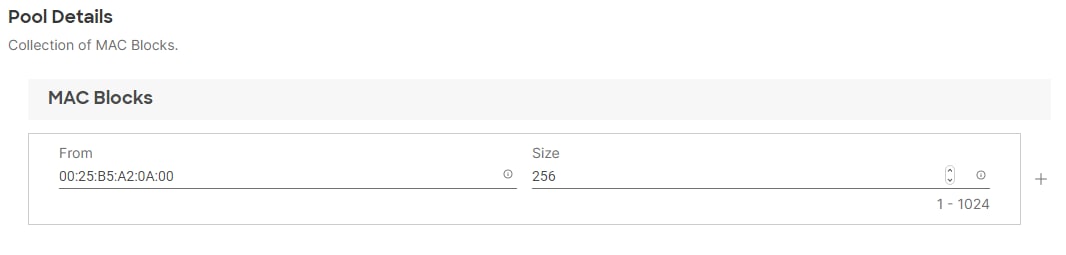
Step 6. Click Create to finish creating the MAC address pool.
Step 7. From the Add vNIC window, provide vNIC Name, Switch ID, and PCI Order information from Table 9 using Simple placement.
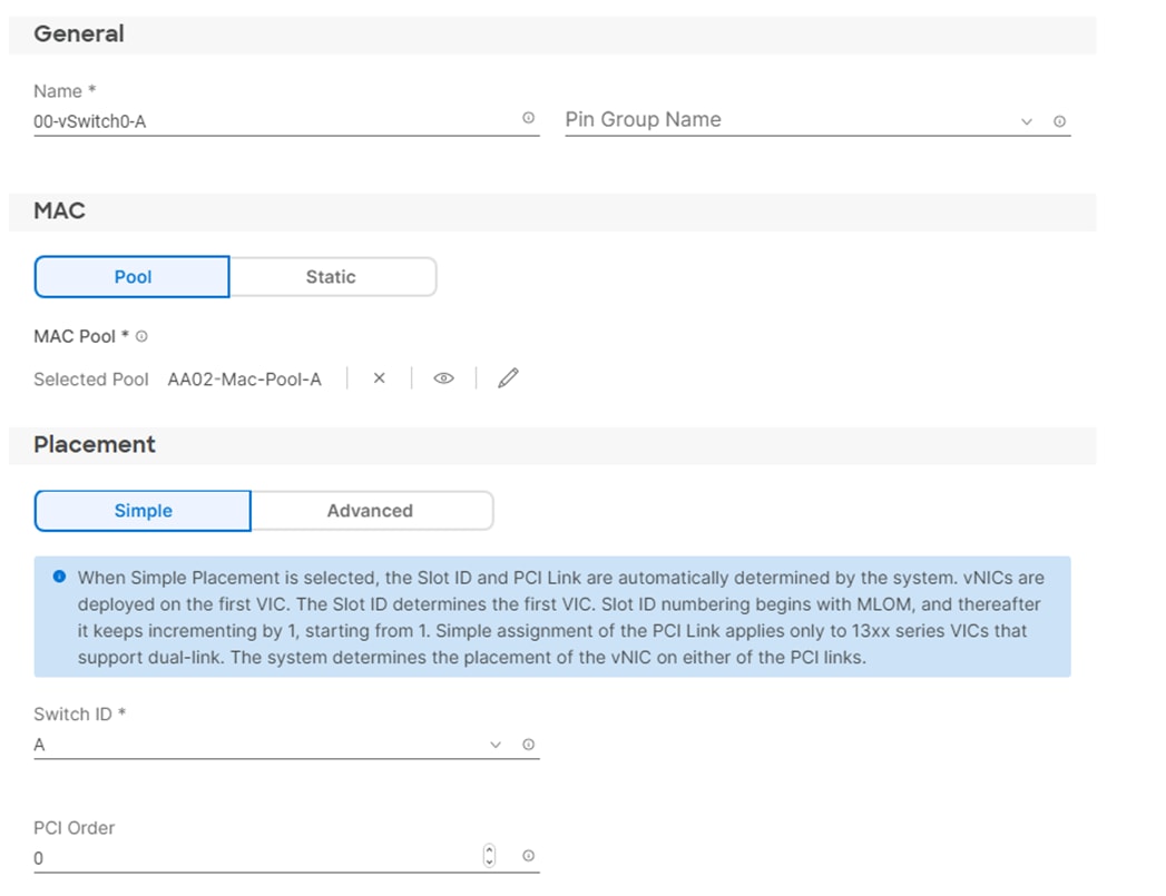
Step 8. For Consistent Device Naming (CDN), from the drop-down list, select vNIC Name.
Step 9. Verify that Failover is disabled because the failover will be provided by attaching multiple NICs to the VMware vSwitch and vDS.
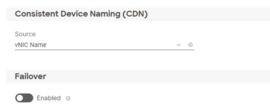
Procedure 8. Create Ethernet Network Group Policy
Ethernet Network Group policies will be created and reused on applicable vNICs as covered below. The ethernet network group policy defines the VLANs allowed for a particular vNIC, therefore multiple network group policies will be defined for this deployment as listed in Table 10.
Table 10. Ethernet Group Policy Values
| Group Policy Name |
Native VLAN |
Apply to vNICs |
VLANs |
| AA02-vSwitch0-NetGrp-Policy |
IB-MGMT (1021) |
01-vSwitch0-A, 02-vSwitch0-B |
OOB-MGMT, IB-MGMT, NFS |
| AA02-vDS0-NetGrp-Policy |
Default (1) |
03-VDS0-A, 04-VDS0-B |
VM Traffic, vMotion, NFS |
| AA02-ISCSI-A-NetGrp-Policy |
iSCSI-A-VLAN (3010) |
05-ISCSI-A |
iSCSI-A-VLAN, NVMe-TCP-A* |
| AA02- ISCSI-B-NetGrp-Policy |
iSCSI-B-VLAN (3020) |
06-ISCSI-B |
iSCSI-B-VLAN, NVMe-TCP-B* |
Note: Add the NVMe-TCP VLANs when using NVMe-TCP.
Step 1. Click Select Policy under Ethernet Network Group Policy and then, in the pane on the right, click Create New.
Step 2. Verify correct organization is selected from the drop-down list (for example, AA02) and provide a name for the policy from the Table 11 (for example, AA02-vSwitch0-NetGrp-Policy).
Step 3. Click Next.
Step 4. Enter the allowed VLANs (for example, 1020,1021,3050) and the native VLAN ID from Table 10 (for example, 1021).
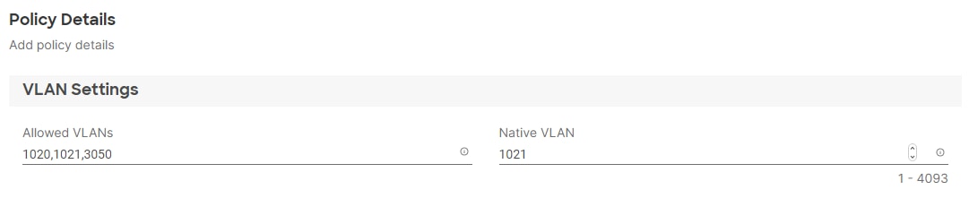
Step 5. Click Create to finish configuring the Ethernet network group policy.
Note: When ethernet group policies are shared between two vNICs, the ethernet group policy only needs to be defined for the first vNIC. For subsequent vNIC policy mapping, click Select Policy and pick the previously defined ethernet group policy from the list.
Procedure 9. Create Ethernet Network Control Policy
The Ethernet Network Control Policy is used to enable Cisco Discovery Protocol (CDP) and Link Layer Discovery Protocol (LLDP) for the vNICs. A single policy will be created here and reused for all the vNICs.
Step 1. Click Select Policy under Ethernet Network Control Policy and then, in the pane on the right, click Create New.
Step 2. Verify correct organization is selected from the drop-down list (for example, AA02) and provide a name for the policy (for example, AA02-Enable-CDP-LLDP).
Step 3. Click Next.
Step 4. Enable Cisco Discovery Protocol and both Enable Transmit and Enable Receive under LLDP.
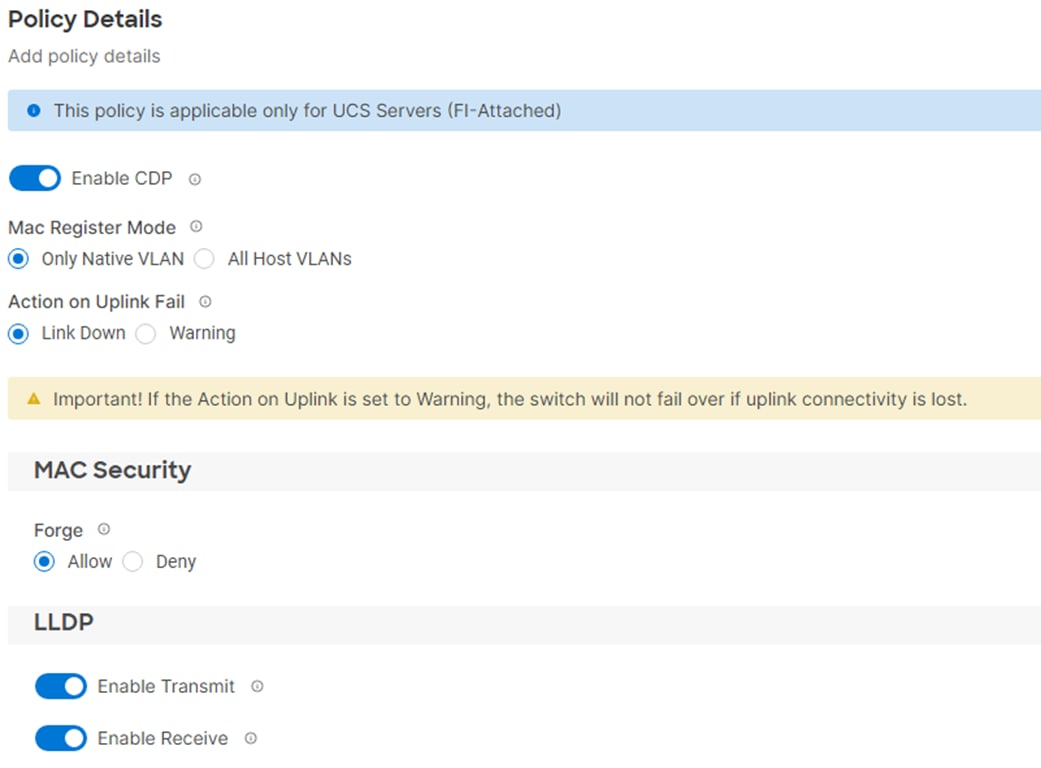
Step 5. Click Create to finish creating Ethernet network control policy.
Procedure 10. Create Ethernet QoS Policy
Note: The Ethernet QoS policy is used to enable jumbo maximum transmission units (MTUs) for all the vNICs. A single policy will be created and reused for all the vNICs.
Step 1. Click Select Policy under Ethernet QoS and in the pane on the right, click Create New.
Step 2. Verify correct organization is selected from the drop-down list (for example, AA02) and provide a name for the policy (for example, AA02-EthernetQos-Policy).
Step 3. Click Next.
Step 4. Change the MTU, Bytes value to 9000.
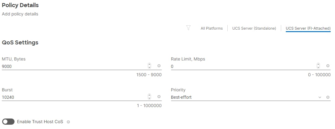
Step 5. Click Create to finish setting up the Ethernet QoS policy.
Procedure 11. Create Ethernet Adapter Policy
The ethernet adapter policy is used to set the interrupts and the send and receive queues. The values are set according to the best-practices guidance for the operating system in use. Cisco Intersight provides default VMware Ethernet Adapter policy for typical VMware deployments.
You can optionally configure a tweaked ethernet adapter policy for additional hardware receive queues handled by multiple CPUs in scenarios where there is a lot of vMotion traffic and multiple flows. In this deployment, a modified ethernet adapter policy, AA17-VMware-High-Traffic, is created and attached to the 03-VDS0-A and 04-VDS0-B interfaces which handle vMotion.
Table 11. Ethernet Adapter Policy association to vNICs
| Policy Name |
vNICs |
| AA02-EthAdapter-VMware-Policy |
00-vSwitch0-A, 01-vSwitch0-B, |
| AA02-EthAdapter-VMware-High-Trf |
02-VDS0-A, 03-VDS0-B |
| AA02-EthAdapter-16RXQs-4G |
04-ISCSI-A, 05-ISCSI-B |
| AA02-EthAdapter-16RXQs-5G |
04-ISCSI-A, 05-ISCSI-B |
Step 1. Click Select Policy under Ethernet Adapter and then, in the pane on the right, click Create New.
Step 2. Verify correct organization is selected from the drop-down list (for example, AA02) and provide a name for the policy (for example, AA02-EthAdapter-VMware-Policy).
Step 3. Click Select Default Configuration under Ethernet Adapter Default Configuration.
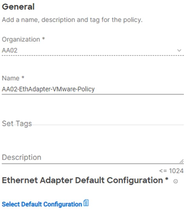
Step 4. From the list, select VMware.
Step 5. Click Next.
Step 6. For the AA02-EthAdapter-VMware-Policy, click Create and skip the rest of the steps in this “Create Ethernet Adapter Policy” section.
Step 7. For the AA02-EthAdapter-VMware-High-Trf policy (for vDS0 interfaces), make the following modifications to the policy:
● Increase Interrupts to 11
● Increase Receive Queue Count to 8
● Increase Receive Ring Size to 4096
● Increase Transmit Ring Size to 4096
● Increase Completion Queue Count to 9
● Enable Receive Side Scaling
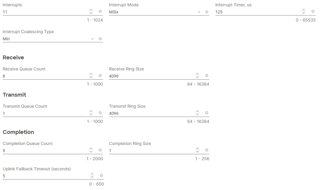

Step 8. For the AA02-EthAdapter-VMware-High-Trf policy (for vDS0 interfaces), make the following modifications to the policy:
● Increase Interrupts to 11
● Increase Receive Queue Count to 8
● Increase Receive Ring Size to 4096
● Increase Transmit Ring Size to 4096
● Increase Completion Queue Count to 9
● Enable Receive Side Scaling
Step 9. For the AA02-EthAdapter-16RXQs-4G policy (for iSCSI interfaces with 4th Generation VICs), make the following modifications to the policy:
● Increase Interrupts to 19
● Increase Receive Queue Count to 16
● Increase Receive Ring Size to 4096
● Increase Transmit Ring Size to 4096
● Increase Completion Queue Count to 17
● Enable Receive Side Scaling
Step 10. For the AA02-EthAdapter-16RXQs-5G policy (for iSCSI interfaces with 5th Generation VICs), make the following modifications to the policy:
● Increase Interrupts to 19
● Increase Receive Queue Count to 16
● Increase Receive Ring Size to 16384
● Increase Transmit Ring Size to 16384
● Increase Completion Queue Count to 17
Step 11. Enable Receive Side Scaling
Step 12. Click Create.
Note: For all the non-ISCSI vNIC, skip the iSCSI-A and iSCSI-B policy creation sections.
Procedure 12. Create iSCSI-A Policy
Note: The iSCSI-A policy is only applied to vNICs 05-ISCSI-A and should not be created for data vNICs (vSwitch0 and VDS). The iSCSI-B policy creation is explained next.
To create this policy, the following information will be gathered from NetApp:
iSCSI Target:
aa02-a800::> iscsi show -vserver Infra-SVM
Vserver: Infra-SVM
Target Name: iqn.1992-08.com.netapp:sn.90e9cb71515311ed978d00a098e217cb:vs.3
Target Alias: Infra-SVM
Administrative Status: up
iSCSI LIFs:
network interface show -vserver Infra-SVM -data-protocol iscsi
Step 1. Click Select Policy under iSCSI Boot and then, in the pane on the right, click Create New.
Step 2. Verify correct organization is selected from the drop-down list (for example, AA02) and provide a name for the policy (for example, AA02-ISCSI-A-Boot-Policy).
Step 3. Click Next.
Step 4. Select Static under Configuration.

Step 5. Click Select Policy under Primary Target and then, in the pane on the right, click Create New.
Step 6. Verify correct organization is selected from the drop-down list (for example, AA02) and provide a name for the policy (for example, AA02-ISCSI-A-Primary-Target).
Step 7. Click Next.
Step 8. Provide the Target Name captured from NetApp, IP Address of iscsi-lif01a, Port 3260 and Lun ID of 0.
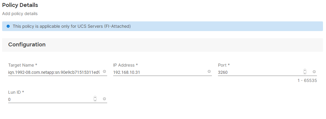
Step 9. Click Create.
Step 10. Click Select Policy under Secondary Target and then, in the pane on the right, click Create New.
Step 11. Verify correct organization is selected from the drop-down list (for example, AA02) and provide a name for the policy (for example, AA02-ISCSI-A-Secondary-Target).
Step 12. Click Next.
Step 13. Provide the Target Name captured from NetApp, IP Address of iscsi-lif02a, Port 3260 and Lun ID of 0
Step 14. Click Create.
Step 15. Click Select Policy under iSCSI Adapter and then, in the pane on the right, click Create New.
Step 16. Verify correct organization is selected from the drop-down list (for example, AA02) and provide a name for the policy (for example, AA02-ISCSI-Adapter-Policy).
Step 17. Click Next.
Step 18. Accept the default policies. Customers can adjust the timers if necessary.
Step 19. Click Create.
Step 20. Scroll down to Initiator IP Source and make sure Pool is selected.
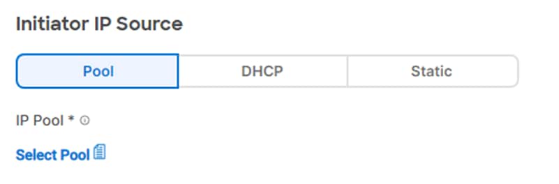
Step 21. Click Select Pool under IP Pool and then, in the pane on the right, click Create New.
Step 22. Verify correct organization is selected from the drop-down list (for example, AA02) and provide a name for the pool (for example, AA02-ISCSI-A-IP-Pool).
Step 23. Click Next.
Step 24. Make sure Configure IPv4 Pool is selected. Enter the IP pool information for iSCSI-A subnet.
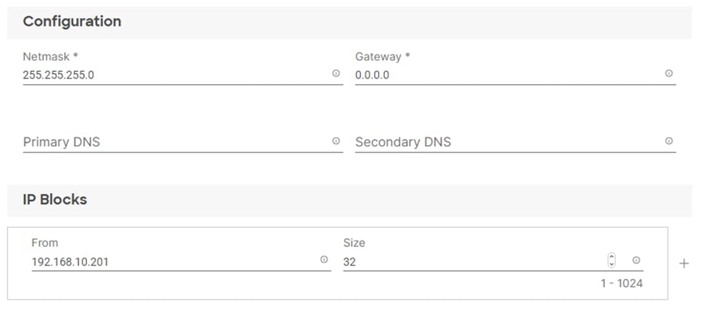
Note: Since the iSCSI network is not routable but the Gateway parameter is required, enter 0.0.0.0 for the Gateway. This will result in a gateway not being set for the interface.
Step 25. Click Next.
Step 26. Disable Configure IPv6 Pool.
Step 27. Click Create.
Step 28. Verify all the policies and pools are correctly mapped for the iSCSI-A policy.
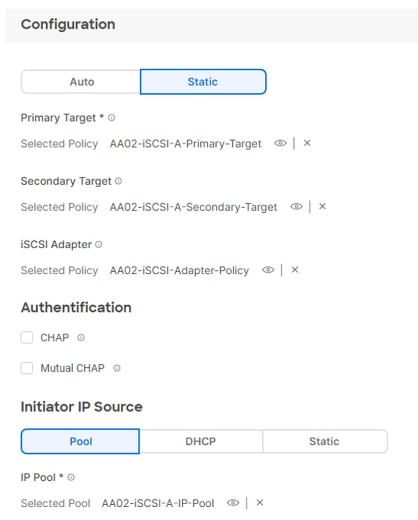
Step 29. Click Create.
Procedure 13. Create iSCSI-B Policy
Note: The iSCSI-B policy is only applied to vNIC 06-ISCSI-B and should not be created for data vNICs (vSwitch0 and vDS0).
Note: To create this policy, the following information will be gathered from NetApp:
iSCSI Target:
aa02-a800::> iscsi show -vserver Infra-SVM
Vserver: Infra-SVM
Target Name: iqn.1992-08.com.netapp:sn.90e9cb71515311ed978d00a098e217cb:vs.3
Target Alias: Infra-SVM
Administrative Status: up
iSCSI LIFs:
network interface show -vserver Infra-SVM -data-protocol iscsi
Step 1. Click Select Policy under iSCSI Boot and then, in the pane on the right, click Create New.
Step 2. Verify correct organization is selected from the drop-down list (for example, AA02) and provide a name for the policy (for example, AA02-iSCSI-Boot-B).
Step 3. Click Next.
Step 4. Select Static under Configuration.
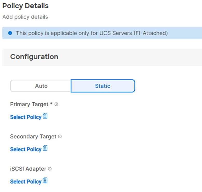
Step 5. Click Select Policy under Primary Target and then, in the pane on the right, click Create New.
Step 6. Verify correct organization is selected from the drop-down list (for example, AA02) and provide a name for the policy (for example, AA02-ISCSI-B-Primary-Target).
Step 7. Click Next.
Step 8. Provide the Target Name captured from NetApp, IP Address of iscsi-lif-01b, Port 3260 and LUN ID of 0.
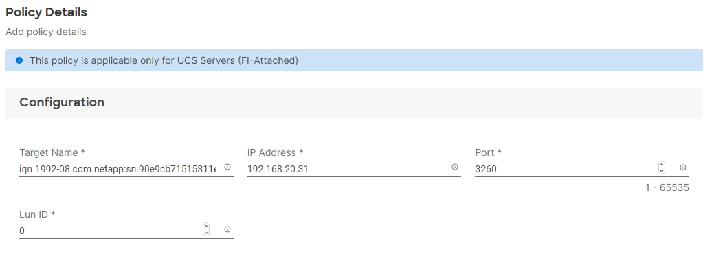
Step 9. Click Create.
Step 10. Click Select Policy under Secondary Target and then, in the pane on the right, click Create New.
Step 11. Verify correct organization is selected from the drop-down list (for example, AA02) and provide a name for the policy (for example, AA02-ISCSI-B-Secondary-Target).
Step 12. Click Next.
Step 13. Provide the Target Name captured from NetApp, IP Address of iscsi-lif02b, Port 3260 and Lun ID of 0
Step 14. Click Create.
Step 15. Click Select Policy under iSCSI Adapter and then, in the pane on the right, select the previously configured adapter policy AA02-ISCSI-Adapter-Policy).
Step 16. Scroll down to Initiator IP Source and make sure Pool is selected.
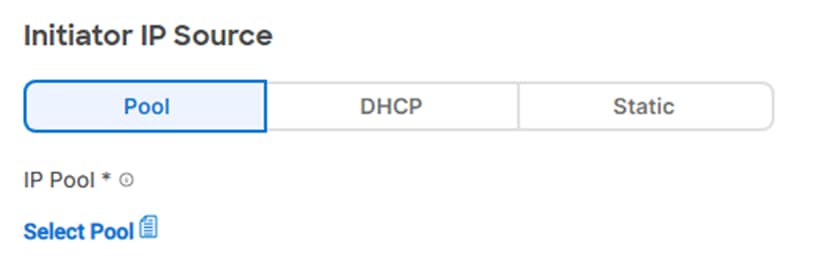
Step 17. Click Select Pool under IP Pool and then, in the pane on the right, click Create New.
Step 18. Verify correct organization is selected from the drop-down list (for example, AA02) and provide a name for the pool (for example, AA02-ISCSI-B-IP-Pool).
Step 19. Click Next.
Step 20. Make sure Configure IPv4 Pool is selected. Enter the IP pool information for iSCSI-B subnet.
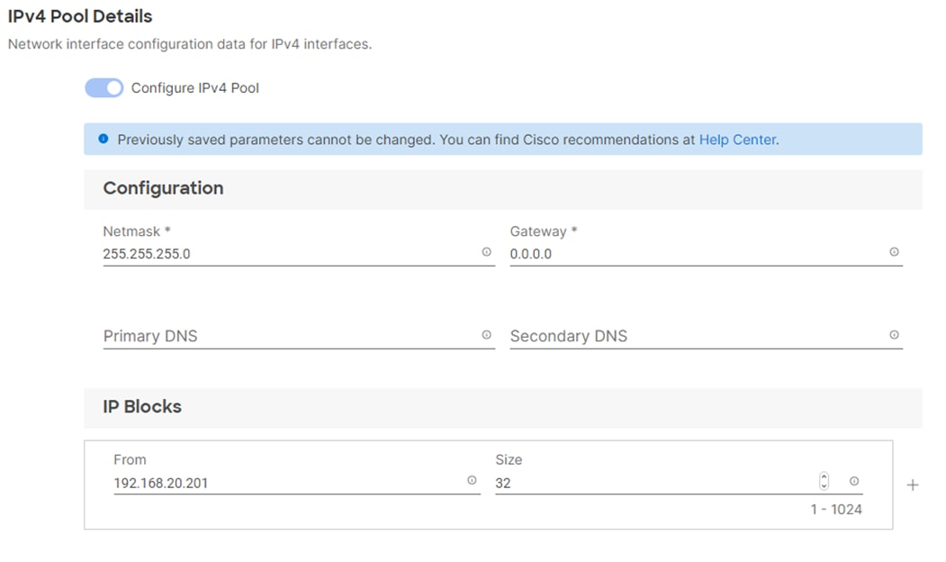
Note: Since the iSCSI network is not routable but the Gateway parameter is required, enter 0.0.0.0 for the Gateway. This will result in a gateway not being set for the interface.
Step 21. Click Next.
Step 22. Disable Configure IPv6 Pool.
Step 23. Click Create.
Step 24. Verify all the policies and pools are correctly mapped for the iSCSI-B policy.
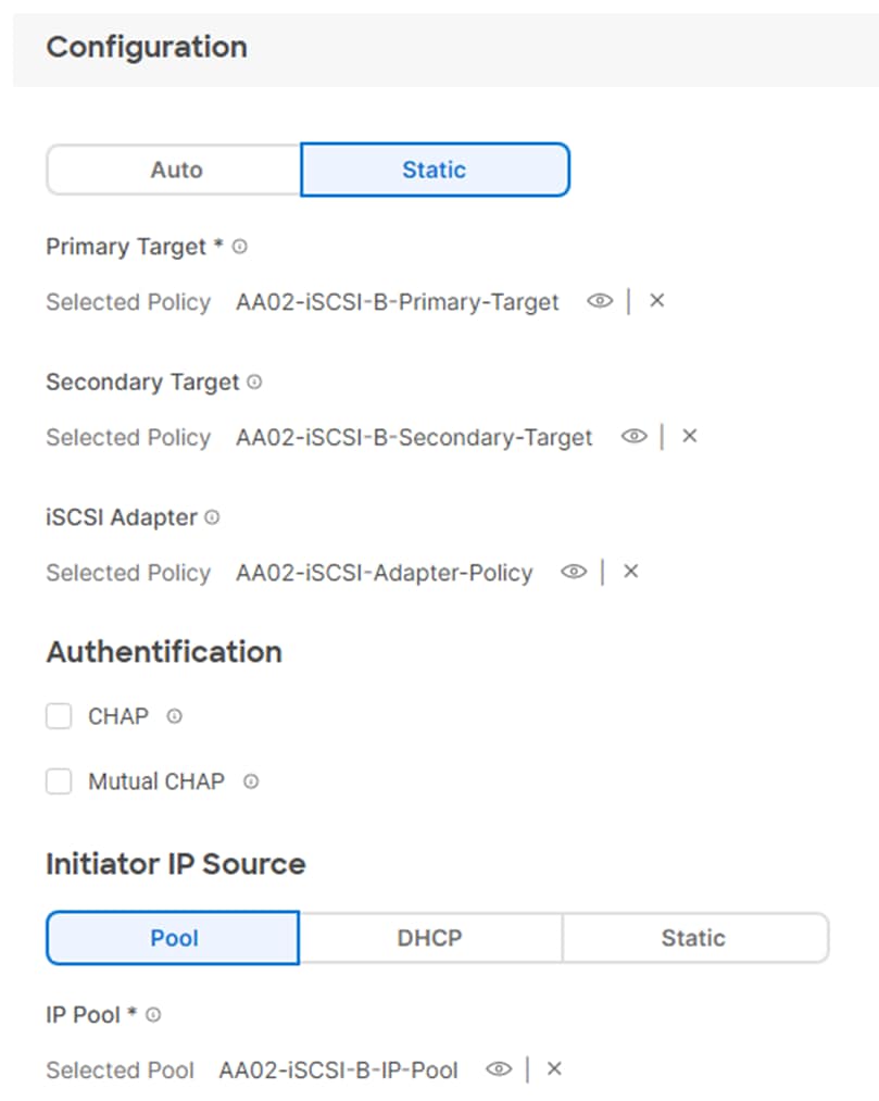
Step 25. Click Create.
Step 26. Click Create to finish creating the vNIC.
Step 27. Go back to Step 10 Add vNIC and repeat the vNIC creation for all six vNICs.
Step 28. Verify all six vNICs were successfully created.
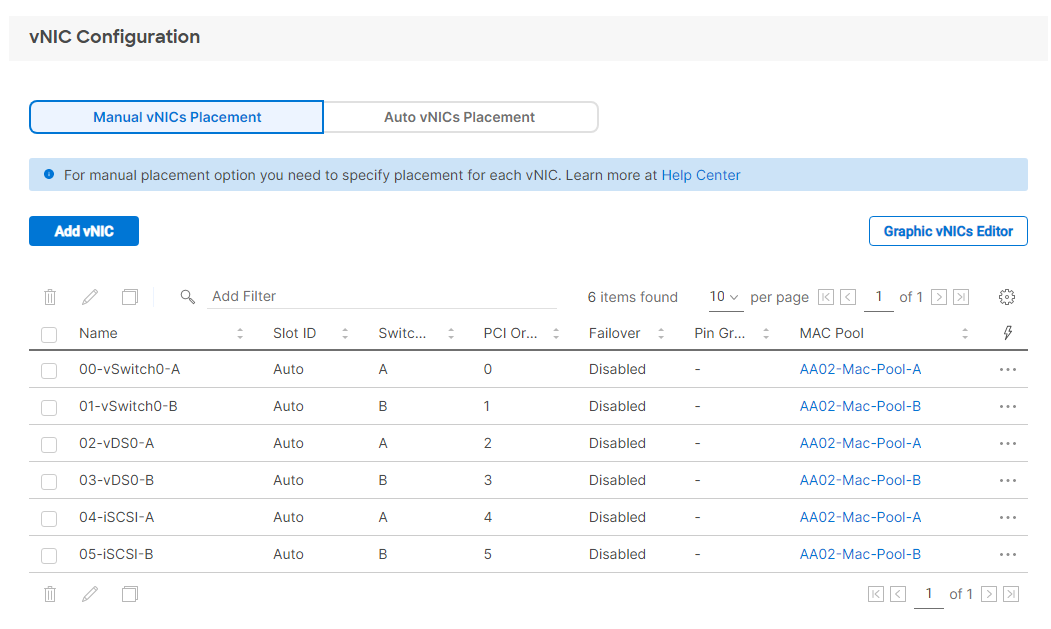
Step 29. Click Create to finish creating the LAN Connectivity policy for iSCSI hosts.
Procedure 14. Create LAN Connectivity Policy for FC Hosts
The FC boot from SAN hosts uses four vNICs configured as listed in Table 12.
Table 12. vNICs for FC LAN Connectivity
| vNIC/vHBA Name |
Switch ID |
PCI Order |
VLANs |
| 00-vSwitch0-A |
A |
0 |
OOB-MGMT, IB-MGMT, NFS |
| 01-vSwitch0-B |
B |
1 |
OOB-MGMT, IB-MGMT, NFS |
| 02-vDS0-A |
A |
2 |
VM Traffic, vMotion, NFS |
| 03-vDS0-B |
B |
3 |
VM Traffic, vMotion, NFS |
Step 1. Click Select Policy next to LAN Connectivity and then, in the pane on the right, click Create New.
Step 2. Verify correct organization is selected from the drop-down list (for example, AA02) and provide a name for the policy (for example, AA02-FC-Boot-5G-LanCon-Pol). Select UCS Server (FI-Attached). Click Next.
Step 3. The four vNICs created in the LAN Connectivity Policy for FC Hosts are identical to the first four vNICs in the LAN Connectivity Policy for iSCSI Hosts. Follow the previous Procedure 6, starting at step 9, only creating the first four vNICs.
Step 4. Verify all four vNICs were successfully created.
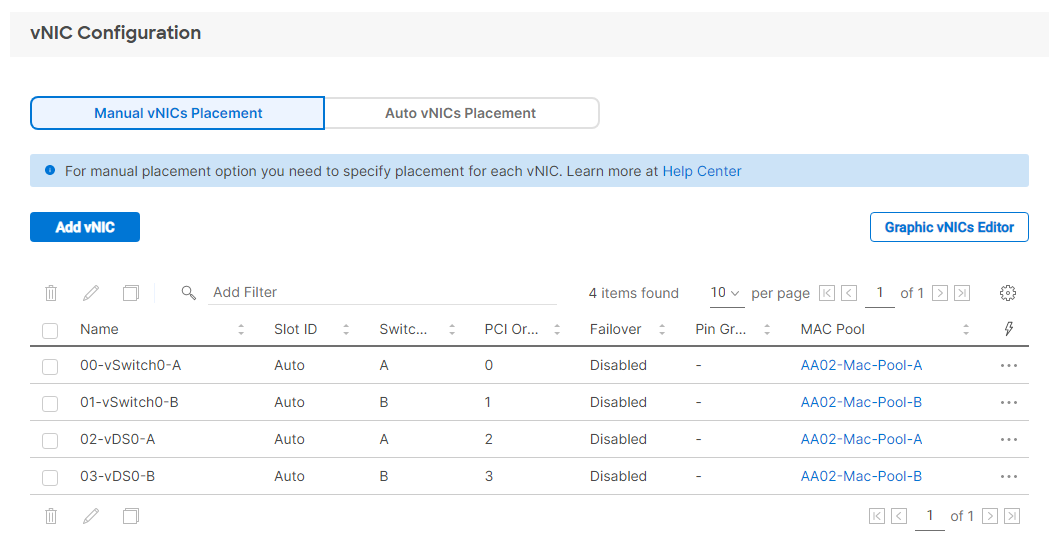
Step 5. Click Create to finish creating the LAN Connectivity policy for FC hosts.
Procedure 15. Create Network Connectivity - SAN Connectivity
A SAN connectivity policy determines the network storage resources and the connections between the server and the storage device on the network. This policy enables customers to configure the vHBAs that the servers use to communicate with the SAN.
Note: A SAN Connectivity policy is not needed for iSCSI boot from SAN hosts and can be skipped.
Table 13 lists the details of two vHBAs that are used to provide FC connectivity and boot from SAN functionality.
Table 13. vHBA for boot from FC SAN
| vNIC/vHBA Name |
Switch ID |
PCI Order |
| FCP-Fabric-A |
A |
4 |
| FCP-Fabric-B |
B |
5 |
Step 1. Click Select Policy next to SAN Connectivity and then, in the pane on the right, click Create New.
Step 2. Verify correct organization is selected from the drop-down list (for example, AA02) and provide a name for the policy (for example, AA02-SanCon). Select UCS Server (FI-Attached). Click Next.
Step 3. Select Manual vHBAs Placement.
Step 4. Select Pool under WWNN Address.
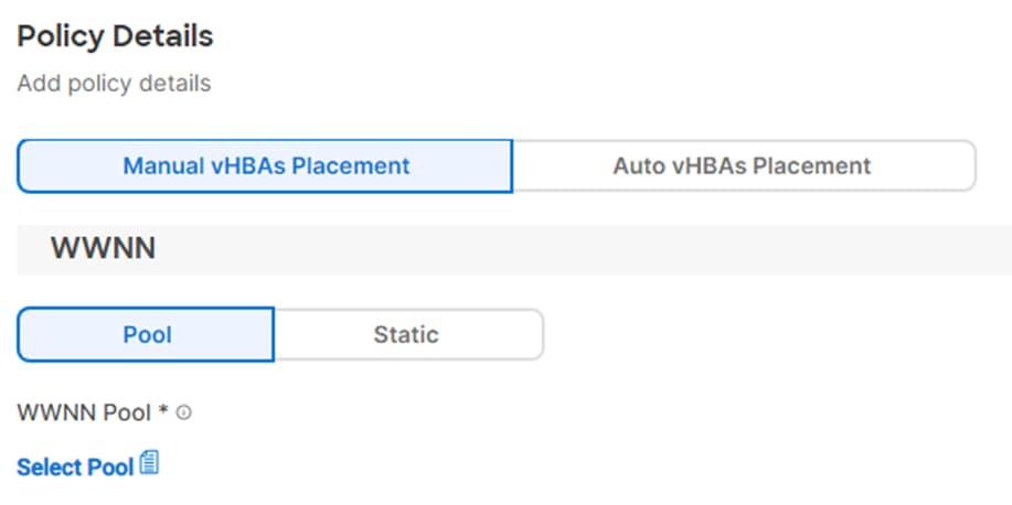
Procedure 16. Create the WWNN Address Pool
The WWNN address pools have not been defined yet therefore a new WWNN address pool has to be defined. To create the WWNN address pool, follow these steps:
Step 1. Click Select Pool under WWNN Address Pool and then, in the pane on the right, click Create New.
Step 2. Verify correct organization is selected from the drop-down list (for example, AA02) and provide a name for the policy (for example, AA02-WWNN-Pool).
Step 3. Click Next.
Step 4. Provide the starting WWNN block address and the size of the pool.
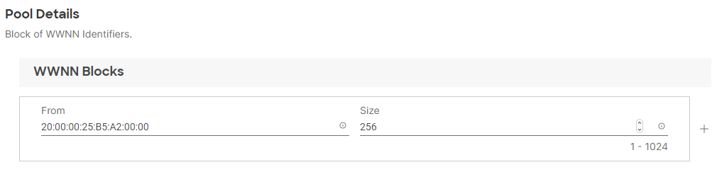
Note: As a best practice, in FlexPod some additional information is always coded into the WWNN address pool for ease of troubleshooting. For example, in the address 20:00:00:25:B5:A2:00:00, A2 is the rack ID.
Step 5. Click Create to finish creating the WWNN address pool.
Procedure 17. Create the vHBA-A for SAN A
Step 1. Click Add vHBA.
Step 2. For vHBA Type, select fc-initiator from the drop-down list.
Procedure 18. Create the WWPN Pool for SAN A
The WWPN address pool has not been defined yet therefore a WWPN address pool for Fabric A will be defined. This pool will also be used for the FC-NVMe vHBAs if the vHBAs are defined.
Step 1. Click Select Pool under WWPN Address Pool and then, in the pane on the right, click Create New.
Step 2. Verify correct organization is selected from the drop-down list (for example, AA02) and provide a name for the policy (for example, AA02-WWPN-Pool-A).
Step 3. Provide the starting WWPN block address for SAN A and the size.
Note: As a best practice, in FlexPod some additional information is always coded into the WWPN address pool for ease of troubleshooting. For example, in the address 20:00:00:25:B5:A2:0A:00, A2 is the rack ID and 0A signifies SAN A.
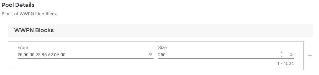
Step 4. Click Create to finish creating the WWPN pool.
Step 5. Back in the Create vHBA window, using Simple Placement, provide the Name (for example, FCP-Fabric-A), vHBA Type, Switch ID (for example, A) and PCI Order from Table 13.
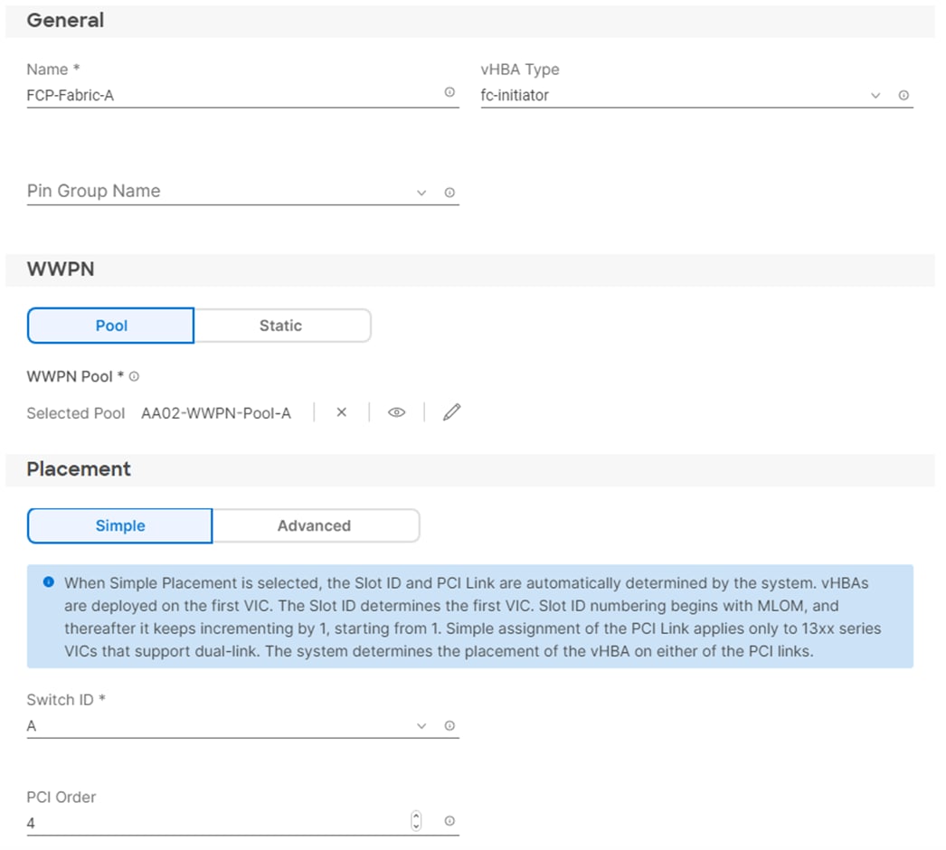
Procedure 19. Create Fibre Channel Network Policy for SAN A
A Fibre Channel network policy governs the VSAN configuration for the virtual interfaces. In this deployment, VSAN 101 will be used for vHBA-A.
Step 1. Click Select Policy under Fibre Channel Network and then, in the pane on the right, click Create New.
Step 2. Verify correct organization is selected from the drop-down list (for example, AA02) and provide a name for the policy (for example, AA02-FC-Network-SAN-A).
Step 3. Under VSAN ID, provide the VSAN information (for example, 101).
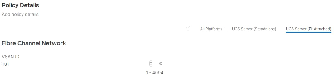
Step 4. Click Create to finish creating the Fibre Channel network policy.
Procedure 20. Create Fibre Channel QoS Policy
The Fibre Channel QoS policy assigns a system class to the outgoing traffic for a vHBA. This system class determines the quality of service for the outgoing traffic. The Fibre Channel QoS policy used in this deployment uses default values and will be shared by all vHBAs.
Step 1. Click Select Policy under Fibre Channel QoS and then, in the pane on the right, click Create New.
Step 2. Verify correct organization is selected from the drop-down list (for example, AA02) and provide a name for the policy (for example, AA02-FC-QoS-Policy).
Step 3. For the scope, select UCS Server (FI-Attached).
Step 4. Do not change the default values on the Policy Details screen.
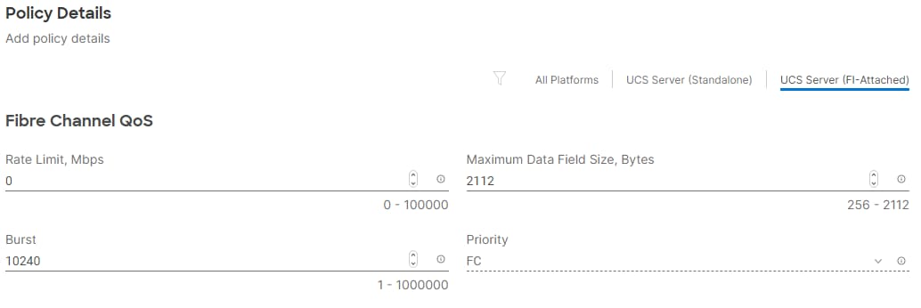
Step 5. Click Create to finish creating the Fibre Channel QoS policy.
Procedure 21. Create Fibre Channel Adapter Policy
A Fibre Channel adapter policy governs the host-side behavior of the adapter, including the way that the adapter handles traffic. This validation uses the default values for the adapter policy, and the policy will be shared by all the vHBAs.
Step 1. Click Select Policy under Fibre Channel Adapter and then, in the pane on the right, click Create New.
Step 2. Verify correct organization is selected from the drop-down list (for example, AA02) and provide a name for the policy (for example, AA02-FC-Adapter).
Step 3. Under Fibre Channel Adapter Default Configuration, click Select Default Configuration.
Step 4. Select VMWare and click Next.
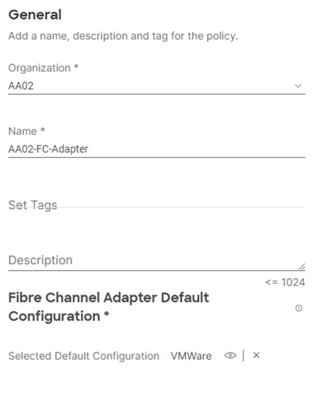
Step 5. For the scope, select UCS Server (FI-Attached).
Step 6. Do not change the default values on the Policy Details screen.
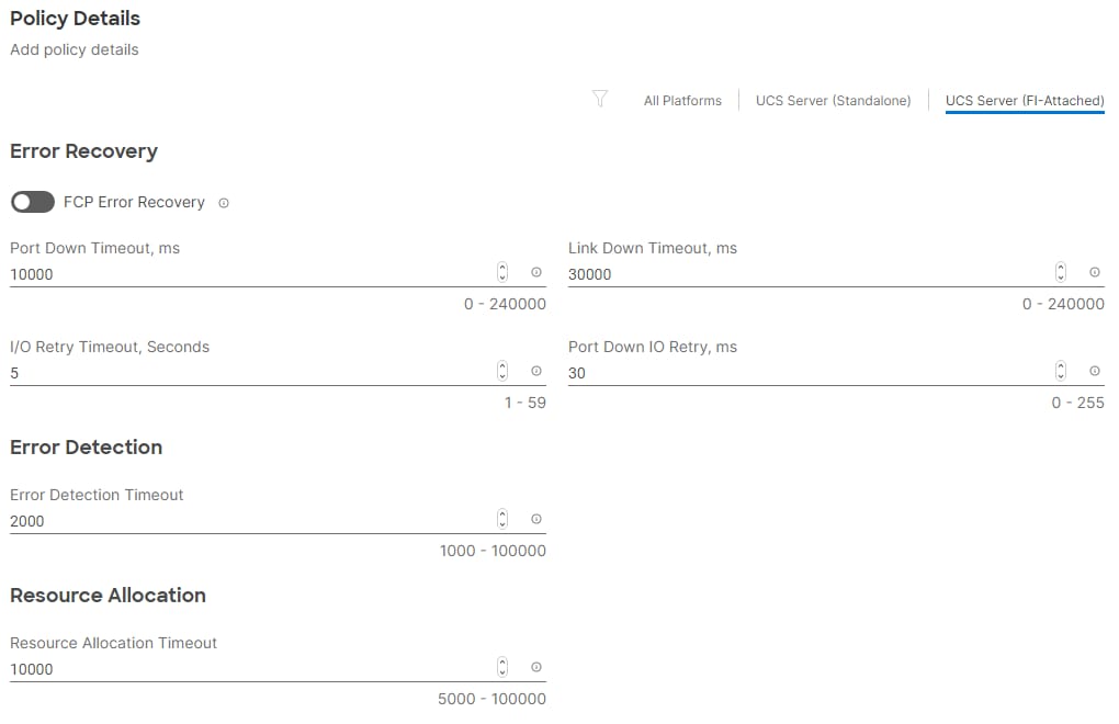
Step 7. Click Create to finish creating the Fibre Channel adapter policy.
Step 8. Click Add to create vHBA FCP-Fabric-A.
Procedure 22. Create the vHBA for SAN B
Step 1. Click Add vHBA.
Step 2. For vHBA Type, select fc-initiator from the drop-down list.
Procedure 23. Create the WWPN Pool for SAN B
The WWPN address pool has not been defined yet therefore a WWPN address pool for Fabric B will be defined. This pool will also be used for the NVMe-FC vHBAs if the vHBAs are defined.
Step 1. Click Select Pool under WWPN Address Pool and then, in the pane on the right, click Create New.
Step 2. Verify correct organization is selected from the drop-down list (for example, AA02) and provide a name for the policy (for example, AA02-WWPN-Pool-B).
Step 3. Provide the starting WWPN block address for SAN B and the size.
Note: As a best practice, in FlexPod some additional information is always coded into the WWPN address pool for ease of troubleshooting. For example, in the address 20:00:00:25:B5:A2:0B:00, A2 is the rack ID and 0B signifies SAN B.
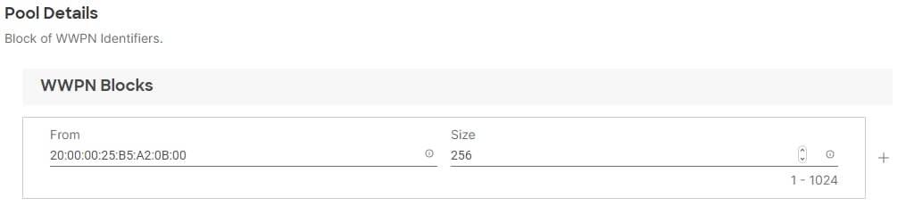
Step 4. Click Create to finish creating the WWPN pool.
Step 5. Back in the Create vHBA window, under Simple Placement, provide the Name (for example, FCP-Fabric-B), Switch ID (for example, B) and PCI Order from Table 13.
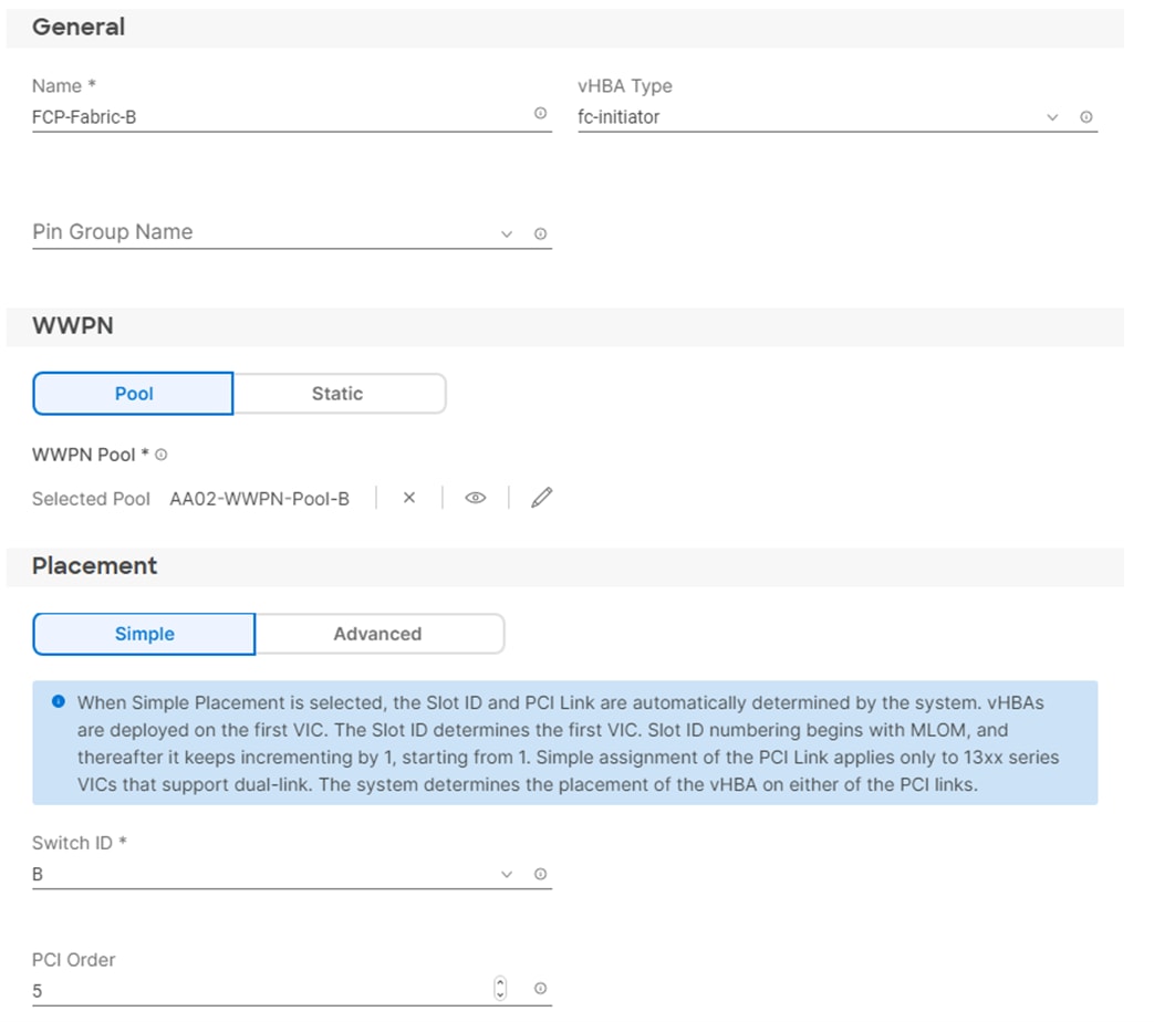
Procedure 24. Create Fibre Channel Network Policy for SAN B
Note: In this deployment, VSAN 102 is used for vHBA FCP-Fabric-B.
Step 1. Click Select Policy under Fibre Channel Network and then, in the pane on the right, click Create New.
Step 2. Verify correct organization is selected from the drop-down list (for example, AA02) and provide a name for the policy (for example, AA02-FC-Network-SAN-B).
Step 3. Under VSAN ID, provide the VSAN information (for example, 102).
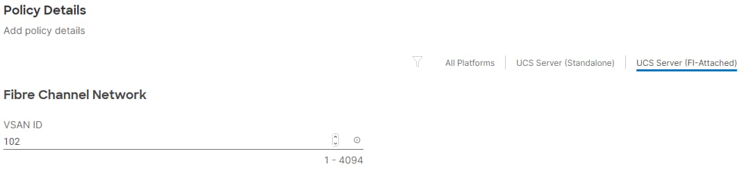
Step 4. Click Create.
Step 5. Select the Fibre Channel QoS Policy for SAN B; click Select Policy under Fibre Channel QoS and then, in the pane on the right, select the previously created QoS policy AA02-FC-QoS-Policy.
Step 6. Select the Fibre Channel Adapter Policy for SAN B; click Select Policy under Fibre Channel Adapter and then, in the pane on the right, select the previously created Adapter policy AA02-FC-Adapter-Policy.
Step 7. Verify all the vHBA policies are mapped.
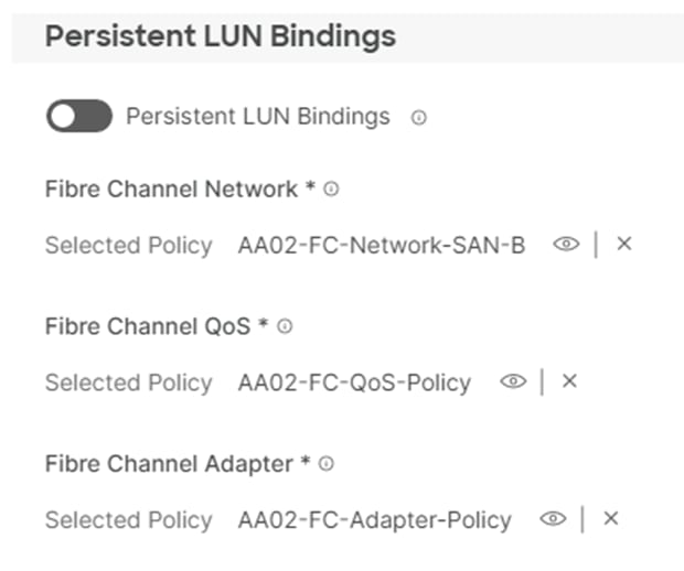
Step 8. Click Add to add the vHBA FCP-Fabric-B.
Step 9. Verify both the vHBAs are added to the SAN connectivity policy.
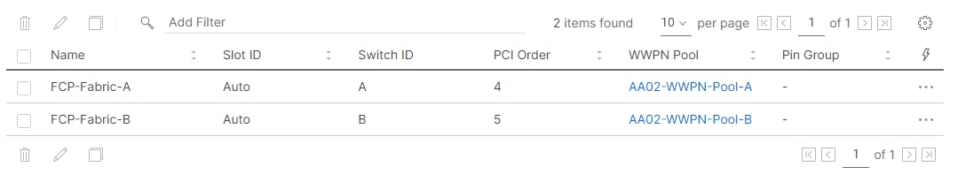
Note: If you don’t need the FC-NVMe connectivity, skip the next sections for creating FC-NVMe vHBAs.
Procedure 25. Create the FC-NVMe vHBAs
Note: To configure (optional) FC-NVMe, two vHBAs, one for each fabric, need to be added to the server profile template. These vHBAs are in addition to the FC boot from SAN vHBAs, FCP-Fabric-A and FCP-Fabric-B.
Table 14. vHBA placement for NVMe-o-FC
| vNIC/vHBA Name |
Switch ID |
PCI Order |
| FC-NVMe-Fabric-A |
A |
6 |
| FC-NVMe-Fabric-B |
B |
7 |
Procedure 26. Configure vHBA-NVMe-A
Step 1. Click Add vHBA.
Step 2. Name the vHBA FC-NVMe-Fabric-A. For vHBA Type, select fc-nvme-initiator from the drop-down list.
Step 3. Click Select Pool under WWPN Address Pool and then, in the pane on the right, select the previously created pool AA02-WWPN-Pool-A.
Step 4. Under Simple Placement, provide the Switch ID (for example, A) and PCI Order from Table 14.
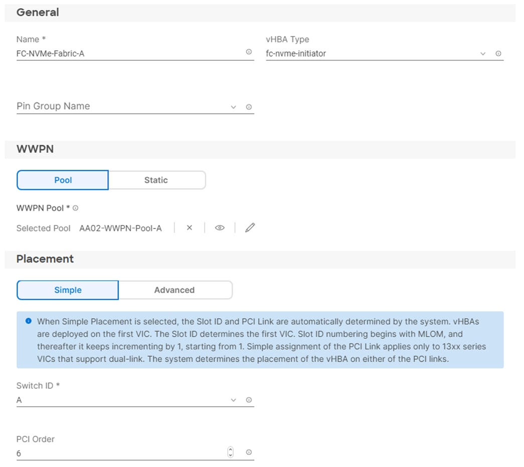
Step 5. Click Select Policy under Fibre Channel Network and then, in the pane on the right, select the previously created policy for SAN A, AA02-FC-Network-SAN-A.
Step 6. Click Select Policy under Fibre Channel QoS and then, in the pane on the right, select the previously created QoS policy AA02-FC-QoS-Policy.
Procedure 27. Create FCNVMeInitiator Fibre Channel Adapter Policy
A Fibre Channel adapter policy governs the host-side behavior of the adapter, including the way that the adapter handles traffic. The FCNVMeInitiator Fibre Channel Adapter Policy is optimized for FC-NVMe.
Step 1. Click Select Policy under Fibre Channel Adapter and then, in the pane on the right, click Create New.
Step 2. Verify the correct organization is selected from the drop-down list (for example, AA02) and provide a name for the policy (for example, AA02-FC-NVMe-Initiator-Adapter-Policy).
Step 3. Under Fibre Channel Adapter Default Configuration, click Select Default Configuration.
Step 4. Select VMWare and click Next.
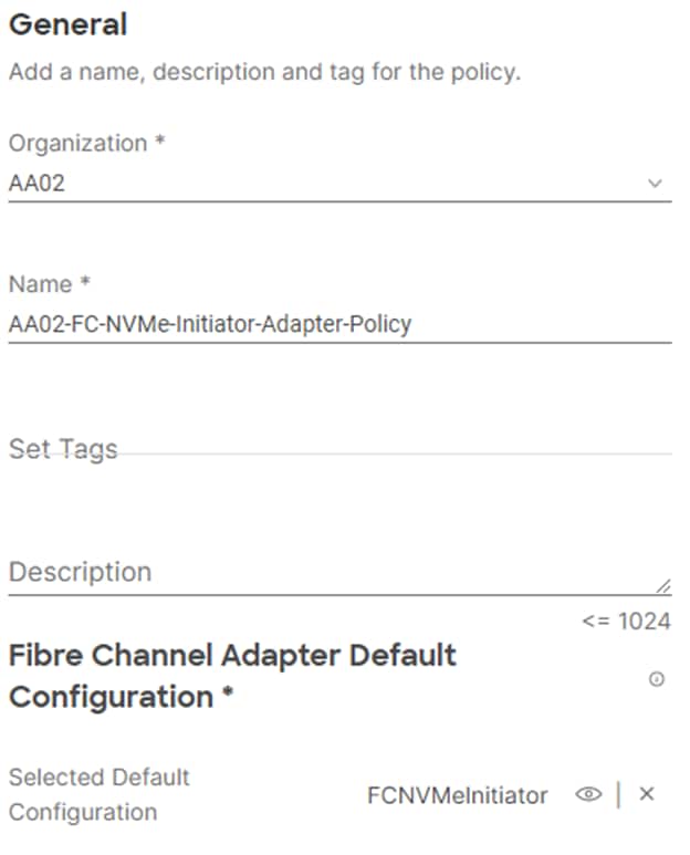
Step 5. For the scope, select UCS Server (FI-Attached).
Step 6. Do not change the default values on the Policy Details screen.
Step 7. Click Create to finish creating the Fibre Channel adapter policy.
Step 8. Verify all the vHBA policies are mapped.
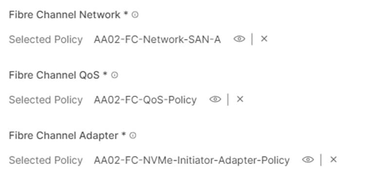
Step 9. Click Add to create vHBA FC-NVMe-Fabric-A.
Procedure 28. Configure vHBA FC-NVMe-Fabric-B
Step 1. Click Add vHBA.
Step 2. Name the vHBA FC-NVMe-Fabric-B. For vHBA Type, select fc-nvme-initiator from the drop-down list.
Step 3. Click Select Pool under WWPN Address Pool and then, in the pane on the right, select the previously created pool AA02-WWPN-Pool-B.
Step 4. Under Simple Placement, provide the Switch ID (for example, B) and PCI Order from Table 14.
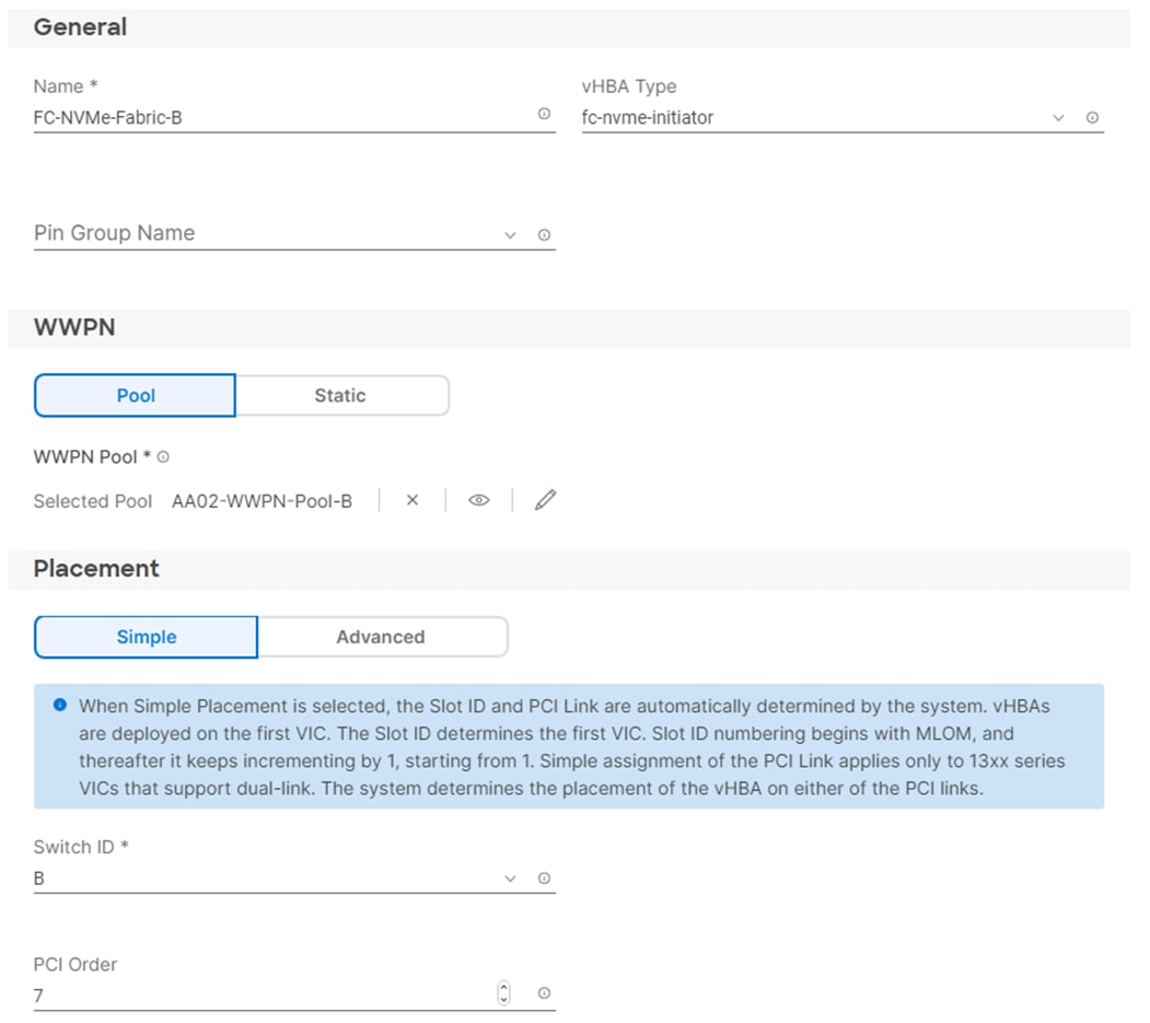
Step 5. Click Select Policy under Fibre Channel Network and then, in the pane on the right, select the previously created policy for SAN B, AA02-FC-Network-SAN-B.
Step 6. Click Select Policy under Fibre Channel QoS and then, in the pane on the right, select the previously created QoS policy AA02-FC-QoS-Policy.
Step 7. Click Select Policy under Fibre Channel Adapter and then, in the pane on the right, select the previously created Adapter policy AA02-FC-NVMe-Initiator-Adapter-Policy.
Step 8. Verify all the vHBA policies are mapped correctly.
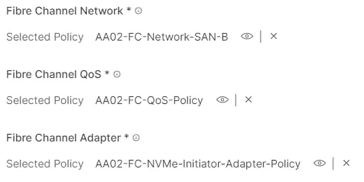
Procedure 29. Verify all vHBAs
Step 1. Verify either two or all four vHBAs are added to the SAN connectivity policy.
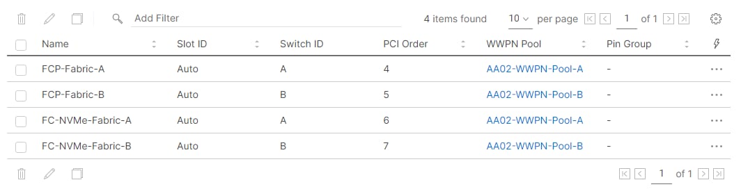
Step 2. Click Create to create the SAN connectivity policy with NVMe-o-FC support.
Step 1. When the LAN connectivity policy and SAN connectivity policy (for FC) is created, click Next to move to the Summary screen.
Step 2. On the summary screen, verify the policies are mapped to various settings. The screenshots below provide summary view for an iSCSI boot from SAN server profile template. An FC boot from SAN server profile template would have a different Boot Order Policy, a different LAN Connectivity Policy, and a SAN Connectivity Policy.
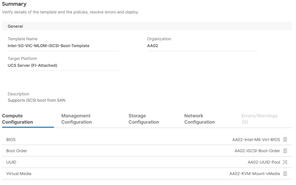
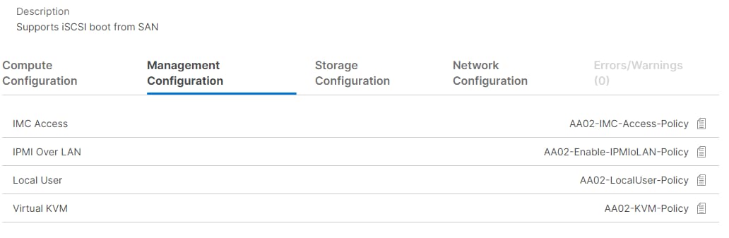
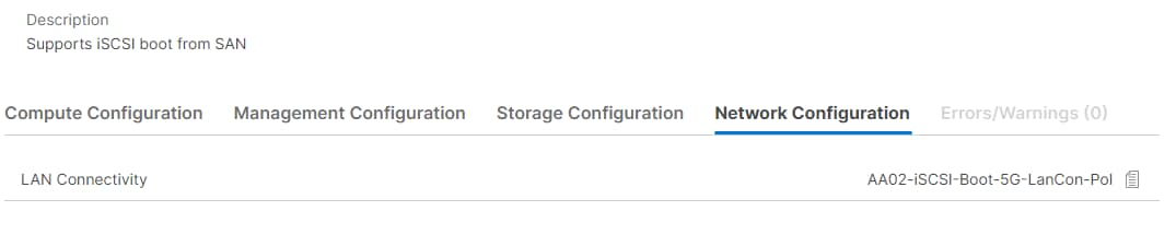
Step 3. Build additional Server Profile Templates to cover different boot options, CPU types, and VIC types.
Cisco UCS IMM Setup Completion
Procedure 1. Derive Server Profiles
Step 1. From the Server profile template Summary screen, click Derive Profiles.
Note: This action can also be performed later by navigating to Templates, clicking “…” next to the template name and selecting Derive Profiles.
Step 2. Under the Server Assignment, select Assign Now and select Cisco UCS X210c M6 server(s). Customers can select one or more servers depending on the number of profiles to be deployed.
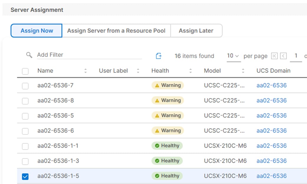
Step 3. Click Next.
Note: Cisco Intersight will fill in the default information for the number of servers selected (1 in this case).
Step 4. Adjust the fields as needed. It is recommended to use the server hostname for the Server Profile name.
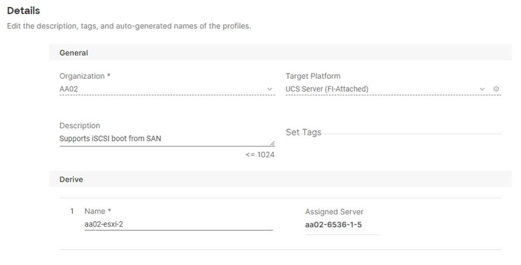
Step 5. Click Next.
Step 6. Verify the information and click Derive to create the Server Profile(s).
Step 7. In the Infrastructure Service > Configure > Profiles > UCS Server Profiles list, select the profile(s) just created and click the … at the top of the column and select Deploy. Click Deploy to confirm.
Step 8. Cisco Intersight will start deploying the server profile(s) and will take some time to apply all the policies. Use the Requests tab at the top right-hand corner of the window to see the progress.

When the Server Profile(s) are deployed successfully, they will appear under the Server Profiles with the status of OK.
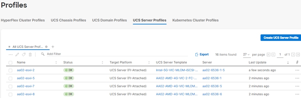
Step 9. Derive and Deploy all needed servers for your FlexPod environment.
This chapter contains the following:
● FlexPod Cisco MDS Switch Manual Configuration
This section explains how to configure the Cisco MDS 9000s for use in a FlexPod environment. The configuration covered in this section is only needed when configuring Fibre Channel and FC-NVMe storage access.
Note: If FC connectivity is not required in the FlexPod deployment, this section can be skipped.
Note: If the Cisco Nexus 93360YC-FX2 switches are being used for SAN switching in this FlexPod Deployment, please refer to FlexPod with Cisco Nexus 93360YC-FX2 SAN Switching Configuration – Part 2 in the Appendix of this document.
Follow the physical connectivity guidelines for FlexPod as explained in Physical Topology section.
The following procedures describe how to configure the Cisco MDS switches for use in a base FlexPod environment. This procedure assumes you are using the Cisco MDS 9132T with NX-OS 8.4(2c).
Procedure 1. Set up Cisco MDS 9132T A and 9132T B
Note: On initial boot and connection to the serial or console port of the switch, the NX-OS setup should automatically start and attempt to enter Power on Auto Provisioning. Enter y to get to the System Admin Account Setup.
Step 1. Configure the switch using the command line:
---- System Admin Account Setup ----
Do you want to enforce secure password standard (yes/no) [y]: Enter
Enter the password for "admin": <password>
Confirm the password for "admin": <password>
Would you like to enter the basic configuration dialog (yes/no): yes
Create another login account (yes/no) [n]: Enter
Configure read-only SNMP community string (yes/no) [n]: Enter
Configure read-write SNMP community string (yes/no) [n]: Enter
Enter the switch name : <mds-A-hostname>
Continue with Out-of-band (mgmt0) management configuration? (yes/no) [y]: Enter
Mgmt0 IPv4 address : <mds-A-mgmt0-ip>
Mgmt0 IPv4 netmask : <mds-A-mgmt0-netmask>
Configure the default gateway? (yes/no) [y]: Enter
IPv4 address of the default gateway : <mds-A-mgmt0-gw>
Configure advanced IP options? (yes/no) [n]: Enter
Enable the ssh service? (yes/no) [y]: Enter
Type of ssh key you would like to generate (dsa/rsa) [rsa]: Enter
Number of rsa key bits <1024-2048> [1024]: Enter
Enable the telnet service? (yes/no) [n]: Enter
Configure congestion/no_credit drop for fc interfaces? (yes/no) [y]: Enter
Enter the type of drop to configure congestion/no_credit drop? (con/no) [c]: Enter
Enter milliseconds in multiples of 10 for congestion-drop for logical-type edge
in range (<200-500>/default), where default is 500. [d]: Enter
Enable the http-server? (yes/no) [y]: Enter
Configure clock? (yes/no) [n]: Enter
Configure timezone? (yes/no) [n]: Enter
Configure summertime? (yes/no) [n]: Enter
Configure the ntp server? (yes/no) [n]: Enter
Configure default switchport interface state (shut/noshut) [shut]: Enter
Configure default switchport trunk mode (on/off/auto) [on]: auto
Configure default switchport port mode F (yes/no) [n]: yes
Configure default zone policy (permit/deny) [deny]: Enter
Enable full zoneset distribution? (yes/no) [n]: y
Configure default zone mode (basic/enhanced) [basic]: Enter
Step 2. Review the configuration.
Would you like to edit the configuration? (yes/no) [n]: Enter
Use this configuration and save it? (yes/no) [y]: Enter
Step 3. To set up the initial configuration of the Cisco MDS B switch, repeat steps 1 and 2 with appropriate host and IP address information.
FlexPod Cisco MDS Switch Manual Configuration
Procedure 1. Enable Features on Cisco MDS 9132T A and Cisco MDS 9132T B Switches
Step 1. Log in as admin.
Step 2. Run the following commands:
configure terminal
feature npiv
feature fport-channel-trunk
Procedure 2. Add NTP Servers and Local Time Configuration on Cisco MDS 9132T A and Cisco MDS 9132T B
Step 1. From the global configuration mode, run the following command:
ntp server <nexus-A-mgmt0-ip>
ntp server <nexus-B-mgmt0-ip>
clock timezone <timezone> <hour-offset> <minute-offset>
clock summer-time <timezone> <start-week> <start-day> <start-month> <start-time> <end-week> <end-day> <end-month> <end-time> <offset-minutes>
Note: It is important to configure the network time so that logging time alignment, any backup schedules, and SAN Analytics forwarding are correct. For more information on configuring the timezone and daylight savings time or summer time, please see Cisco MDS 9000 Series Fundamentals Configuration Guide, Release 9.x. Sample clock commands for the United States Eastern timezone are:
clock timezone EST -5 0
clock summer-time EDT 2 Sunday March 02:00 1 Sunday November 02:00 60
Procedure 1. Cisco MDS 9132T A
Step 1. From the global configuration mode, run the following commands:
channel mode active
switchport trunk allowed vsan <vsan-a-id for example, 101>
switchport description <ucs-domainname>-a
switchport speed 32000
no shutdown
!
interface fc1/5
switchport description <ucs-domainname>-a:1/35/1
channel-group 15 force
port-license acquire
no shutdown
!
interface fc1/6
switchport description <ucs-clustername>-a:1/35/2
channel-group 15 force
port-license acquire
no shutdown
!
interface fc1/7
switchport description <ucs-domainname>-a:1/35/3
channel-group 15 force
port-license acquire
no shutdown
!
interface fc1/8
switchport description <ucs-clustername>-a:1/35/4
channel-group 15 force
port-license acquire
no shutdown
!
interface fc1/9
switchport description <st-clustername>-01:2a
switchport speed 32000
switchport trunk mode off
port-license acquire
no shutdown
!
interface fc1/10
switchport description <st-clustername>-01:2c
switchport speed 32000
switchport trunk mode off
port-license acquire
no shutdown
!
interface fc1/11
switchport description <st-clustername>-02:2a
switchport speed 32000
switchport trunk mode off
port-license acquire
no shutdown
!
interface fc1/12
switchport description <st-clustername>-02:2c
switchport speed 32000
switchport trunk mode off
port-license acquire
no shutdown
Procedure 2. Cisco MDS 9132T B
Step 1. From the global configuration mode, run the following commands:
interface port-channel15
channel mode active
switchport trunk allowed vsan <vsan-b-id for example, 102>
switchport description <ucs-domainname>-b
switchport speed 32000
no shutdown
!
interface fc1/5
switchport description <ucs-domainname>-b:1/35/1
channel-group 15 force
port-license acquire
no shutdown
!
interface fc1/6
switchport description <ucs-clustername>-b:1/35/2
channel-group 15 force
port-license acquire
no shutdown
!
interface fc1/7
switchport description <ucs-domainname>-b:1/35/3
channel-group 15 force
port-license acquire
no shutdown
!
interface fc1/8
switchport description <ucs-clustername>-b:1/35/4
channel-group 15 force
port-license acquire
no shutdown
!
interface fc1/9
switchport description <st-clustername>-01:2b
switchport speed 32000
switchport trunk mode off
port-license acquire
no shutdown
!
interface fc1/10
switchport description <st-clustername>-01:2d
switchport speed 32000
switchport trunk mode off
port-license acquire
no shutdown
!
interface fc1/11
switchport description <st-clustername>-02:2b
switchport speed 32000
switchport trunk mode off
port-license acquire
no shutdown
!
interface fc1/12
switchport description <st-clustername>-02:2d
switchport speed 32000
switchport trunk mode off
port-license acquire
no shutdown
Note: If VSAN trunk is not configured between the Cisco UCS Fabric Interconnects and the Cisco MDS switches, do not enter “switchport trunk allowed vsan <vsan-b-id>” for interface port-channel15.
Procedure 1. Cisco MDS 9132T A
Step 1. From the global configuration mode, run the following commands:
vsan database
vsan <vsan-a-id>
vsan <vsan-a-id> name Fabric-A
exit
zone smart-zoning enable vsan <vsan-a-id>
vsan database
vsan <vsan-a-id> interface fc1/9
Traffic on fc1/9 may be impacted. Do you want to continue? (y/n) [n] y
vsan <vsan-a-id> interface fc1/10
Traffic on fc1/10 may be impacted. Do you want to continue? (y/n) [n] y
vsan <vsan-a-id> interface fc1/11
Traffic on fc1/11 may be impacted. Do you want to continue? (y/n) [n] y
vsan <vsan-a-id> interface fc1/12
Traffic on fc1/12 may be impacted. Do you want to continue? (y/n) [n] y
vsan <vsan-a-id> interface port-channel15
exit
Procedure 2. Cisco MDS 9132T B
Step 1. From the global configuration mode, run the following commands:
vsan database
vsan <vsan-b-id>
vsan <vsan-b-id> name Fabric-B
exit
zone smart-zoning enable vsan <vsan-b-id>
vsan database
vsan <vsan-b-id> interface fc1/9
Traffic on fc1/9 may be impacted. Do you want to continue? (y/n) [n] y
vsan <vsan-b-id> interface fc1/10
Traffic on fc1/10 may be impacted. Do you want to continue? (y/n) [n] y
vsan <vsan-b-id> interface fc1/11
Traffic on fc1/11 may be impacted. Do you want to continue? (y/n) [n] y
vsan <vsan-b-id> interface fc1/12
Traffic on fc1/12 may be impacted. Do you want to continue? (y/n) [n] y
vsan <vsan-b-id> interface port-channel15
exit
Procedure 1. Cisco MDS 9132T A
Step 1. The WWPN information required to create device-alias and zones can be gathered from NetApp using the following command:
network interface show -vserver <svm-name> -data-protocol fcp
network interface show -vserver <svm-name> -data-protocol fc-nvme
Step 2. The WWPN information for a Server Profile can be obtained by logging into Intersight, go Cisco Intersight and select each of the 3 server service profiles by going to Infrastructure Service > Configure > Profiles > UCS Server Profiles > <Desired Server Profile> > Inventory > Network Adapters > <Adapter> > Interfaces . The needed WWPNs can be found under HBA Interfaces.
Procedure 2. Create Device Aliases for Fabric A used to Create Zones
Step 1. From the global configuration mode, run the following commands:
device-alias mode enhanced
device-alias database
device-alias name <svm-name>-fcp-lif-01a pwwn <fcp-lif-01a-wwpn>
device-alias name <svm-name>-fcp-lif-02a pwwn <fcp-lif-02a-wwpn>
device-alias name FCP-<server1-hostname>-A pwwn <fcp-server1-wwpna>
device-alias name FCP-<server2-hostname>-A pwwn <fcp-server2-wwpna>
device-alias name FCP-<server3-hostname>-A pwwn <fcp-server3-wwpna>
Step 2. If configuring FC-NVMe, the following device alias entries also needs to be defined:
device-alias name <svm-name>-fc-nvme-lif-01a pwwn <fc-nvme-lif-01a-wwpn>
device-alias name <svm-name>-fc-nvme-lif-02a pwwn <fc-nvme-lif-02a-wwpn>
device-alias name FC-NVMe-<server1>-A pwwn <fc-nvme-server1-wwpna>
device-alias name FC-NVMe-<server2>-A pwwn <fc-nvme-server2-wwpna>
device-alias name FC-NVMe-<server3>-A pwwn <fc-nvme-server3-wwpna>
Step 3. Commit the device alias database changes:
device-alias commit
Procedure 3. Cisco MDS 9132T B
Step 1. The WWPN information required to create device-alias and zones can be gathered from NetApp using the following command:
network interface show -vserver Infra-SVM -data-protocol fcp
network interface show -vserver <svm-name> -data-protocol fc-nvme
Step 2. The WWPN information for a Server Profile can be obtained by logging into Intersight, go Cisco Intersight and select each of the 3 server service profiles by going to Infrastructure Service > Configure > Profiles > UCS Server Profiles > <Desired Server Profile> > Inventory > Network Adapters > <Adapter> > Interfaces . The needed WWPNs can be found under HBA Interfaces.
Procedure 4. Create Device Aliases for Fabric B used to Create Zones
Step 1. From the global configuration mode, run the following commands:
device-alias mode enhanced
device-alias database
device-alias name <svm-name>-fcp-lif-01b pwwn <fcp-lif-01b-wwpn>
device-alias name <svm-name>-fcp-lif-02b pwwn <fcp-lif-02b-wwpn>
device-alias name FCP-<server1-hostname>-B pwwn <fcp-server1-wwpnb>
device-alias name FCP-<server2-hostname>-B pwwn <fcp-server2-wwpnb>
device-alias name FCP-<server3-hostname>-B pwwn <fcp-server3-wwpnb>
Step 2. If configuring FC-NVMe, following device alias entries also needs to be defined:
device-alias name <svm-name>-fc-nvme-lif-01b pwwn <fc-nvme-lif-01b-wwpn>
device-alias name <svm-name>-fc-nvme-lif-02b pwwn <fc-nvme-lif-02b-wwpn>
device-alias name FC-NVMe-<server1>-B pwwn <fc-nvme-server1-wwpnb>
device-alias name FC-NVMe-<server2>-B pwwn <fc-nvme-server2-wwpnb>
device-alias name FC-NVMe-<server3>-B pwwn <fc-nvme-server3-wwpnb>
Step 3. Commit the device alias database changes:
device-alias commit
Procedure 1. Cisco MDS 9132T A
Step 1. To create the required zones for FC on Fabric A, run the following commands:
configure terminal
zone name FCP-<svm-name>-A vsan <vsan-a-id>
member device-alias FCP-<server1-hostname>-A init
member device-alias FCP-<server2-hostname>-A init
member device-alias FCP-<server3-hostname>-A init
member device-alias <svm-name>-fcp-lif-01a target
member device-alias <svm-name>-fcp-lif-02a target
exit
Step 2. To create the required zones for FC-NVMe on Fabric A, run the following commands:
zone name FC-NVMe-<svm-name>-A vsan <vsan-a-id>
member device-alias FC-NVMe-<server1-hostname>-A init
member device-alias FC-NVMe-<server2-hostname>-A init
member device-alias FC-NVMe-<server2-hostname>-A init
member device-alias <svm-name>-fc-nvme-lif-01a target
member device-alias <svm-name>-fc-nvme-lif-02a target
exit
Step 3. To create the zoneset for the zone(s) defined above, issue the following command:
zoneset name FlexPod-Fabric-A vsan <vsan-a-id>
member FCP-<svm-name>-A
member FC-NVMe-<svm-name>-A
exit
Step 4. Activate the zoneset:
zoneset activate name FlexPod-Fabric-A vsan <vsan-a-id>
Step 5. Save the configuration:
copy run start
Note: Since Smart Zoning is enabled, a single zone for each storage protocol (FCP and FC-NVMe) is created with all host initiators and targets for the Infra_SVM instead of creating separate zones for each host. If a new host is added, its initiator can simply be added to appropriate zone in each MDS switch and the zoneset is reactivated.
Procedure 2. Cisco MDS 9132T B
Step 1. To create the required zones and zoneset on Fabric B, run the following commands:
configure terminal
zone name FCP-Infra-SVM-B vsan <vsan-b-id>
member device-alias FCP-<server1-hostname>-B init
member device-alias FCP-<server2-hostname>-B init
member device-alias FCP-<server3-hostname>-B init
member device-alias <svm-name>-fcp-lif-01b target
member device-alias <svm-name>-fcp-lif-02b target
exit
Step 2. To create the required zones for FC-NVMe on Fabric A, run the following commands:
zone name FC-NVMe-Infra-SVM-B vsan <vsan-b-id>
member device-alias FC-NVMe-<server1-hostname>-B init
member device-alias FC-NVMe-<server1-hostname>-B init
member device-alias FC-NVMe-<server1-hostname>-B init
member device-alias <svm-name>-fc-nvme-lif-01b target
member device-alias <svm-name>-fc-nvme-lif-02b target
exit
Step 3. To create the zoneset for the zone(s) defined above, issue the following command:
zoneset name FlexPod-Fabric-B vsan <vsan-b-id>
member FCP-<svm-name>-B
member FC-NVMe-<svm-name>-B
exit
Step 4. Activate the zoneset:
zoneset activate name FlexPod-Fabric-B vsan <vsan-b-id>
Step 5. Save the configuration:
copy run start
Storage Configuration – NetApp ONTAP Boot Storage Setup
This chapter contains the following:
● Manual NetApp ONTAP Storage Configuration Part 2
This configuration requires information from both the server profiles and NetApp storage system. After creating the boot LUNs, initiator groups, and appropriate mappings between the two, UCS server profiles will be able to see the boot disks hosted on NetApp controllers.
Manual NetApp ONTAP Storage Configuration Part 2
This section provides detailed information about the manual steps to configure NetApp ONTAP Boot storage.
Step 1. Run the following command on the NetApp Cluster Management Console to create boot LUNs for the ESXi servers:
lun create -vserver <infra-data-svm> -path <path> -size <lun-size> -ostype vmware -space-reserve disabled
The following commands were issued for configuring FC and ISCSI boot LUNs respectively:
lun create -vserver Infra-SVM -path /vol/esxi_boot/aa02-esxi-1-FCP -size 128GB -ostype vmware -space-reserve disabled
lun create -vserver Infra-SVM -path /vol/esxi_boot/aa02-esxi-3-FCP -size 128GB -ostype vmware -space-reserve disabled
lun create -vserver Infra-SVM -path /vol/esxi_boot/aa02-esxi-5-FCP -size 128GB -ostype vmware -space-reserve disabled
lun create -vserver Infra-SVM -path /vol/esxi_boot/aa02-esxi-2-ISCSI -size 128GB -ostype vmware -space-reserve disabled
lun create -vserver Infra-SVM -path /vol/esxi_boot/aa02-esxi-4-ISCSI -size 128GB -ostype vmware -space-reserve disabled
Procedure 1. Obtain the WWPNs for UCS Server Profiles (required only for FC configuration)
Step 1. From the Intersight GUI, follow: CONFIGURE > Profiles. Select UCS Server Profile and click on [Server Profile Name]. Under Inventory, expand Network Adapters and click on the Adapter. Select Interfaces sub tab and scroll down to find the WWPN information for various vHBAs.
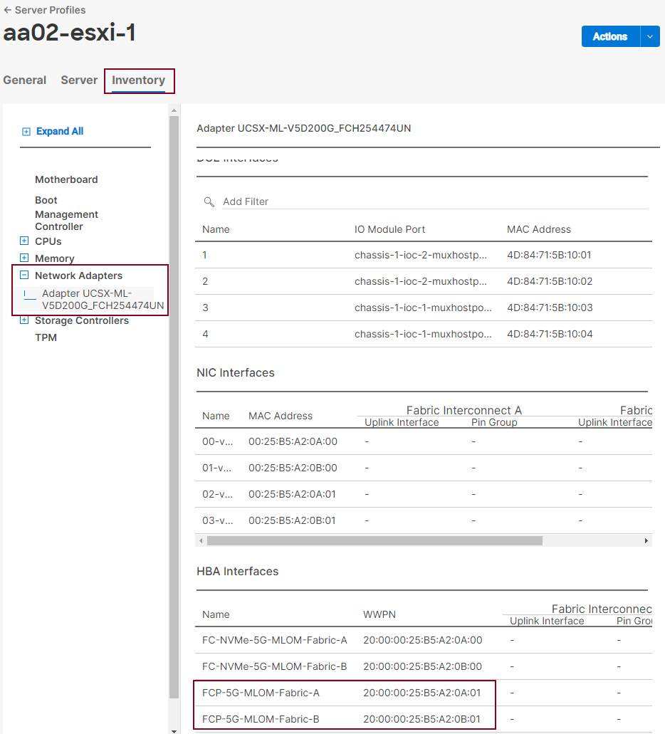
Procedure 2. Obtain the IQNs for UCS Server Profiles (required only for iSCSI configuration)
Step 1. From Intersight GUI, go to: CONFIGURE > Pools > [IQN Pool Name] > Usage and find the IQN information for various ESXi servers:
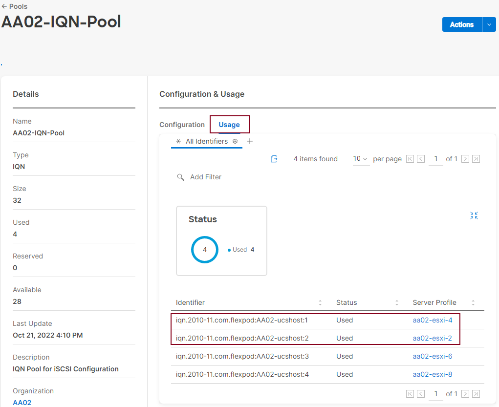
Procedure 3. Create Initiator Groups for FC Storage Access
Step 1. Run the following command on the NetApp Cluster Management Console to create the fcp initiator groups (igroups):
lun igroup create –vserver <infra-data-svm> –igroup <igroup-name> –protocol fcp –ostype vmware –initiator <vm-host-wwpna>, <vm-host-wwpnb>
Step 2. To access boot LUNs, following FCP igroups for individual hosts are created:
lun igroup create –vserver Infra-SVM –igroup aa02-esxi-3-FCP –protocol fcp –ostype vmware –initiator 20:00:00:25:b5:a2:0a:02, 20:00:00:25:b5:a2:0b:02
lun igroup create –vserver Infra-SVM –igroup aa02-esxi-5-FCP –protocol fcp –ostype vmware –initiator 20:00:00:25:b5:a2:0a:04, 20:00:00:25:b5:a2:0b:04
Step 3. To view and verify the FC igroups just created, use the following command:
aa02-a800::> lun igroup show -vserver Infra-SVM -protocol fcp
Vserver Igroup Protocol OS Type Initiators
--------- ------------ -------- -------- ------------------------------------
Infra-SVM aa02-esxi-1-FCP
fcp vmware 20:00:00:25:b5:a2:0a:01
20:00:00:25:b5:a2:0b:01
Infra-SVM aa02-esxi-3-FCP
fcp vmware 20:00:00:25:b5:a2:0a:02
20:00:00:25:b5:a2:0b:02
Infra-SVM aa02-esxi-5-FCP
fcp vmware 20:00:00:25:b5:a2:0a:04
20:00:00:25:b5:a2:0b:04
--------- ------------ -------- -------- ------------------------------------
3 entries were displayed.
Step 4. (Optional) To access a common datastore from all the hosts, a common igroup for all the servers can be created as follows:
lun igroup create –vserver Infra-SVM –igroup MGMT-Hosts –protocol fcp –ostype vmware –initiator <vm-host-infra-01-wwpna>, <vm-host-infra-01-wwpnb>, <vm-host-infra-03-wwpna>, <vm-host-infra-03-wwpnb>, <vm-host-infra-05-wwpna>, <vm-host-infra-05-wwpnb>
Procedure 4. Create Initiator Groups for iSCSI Storage Access
Step 1. Run the following command on NetApp Cluster Management Console to create iscsi initiator groups (igroups):
lun igroup create –vserver <infra-data-svm> –igroup <igroup-name> –protocol iscsi –ostype vmware –initiator <vm-host-iqn>
Step 2. The following commands were issued for setting up ISCSI initiator groups.
lun igroup create –vserver Infra-SVM –igroup aa02-esxi-2-ISCSI –protocol iscsi –ostype vmware -initiator iqn.2010-11.com.flexpod:aa02-ucshost:2
lun igroup create –vserver Infra-SVM –igroup aa02-esxi-4-ISCSI –protocol iscsi –ostype vmware –initiator iqn.2010-11.com.flexpod:aa02-ucshost:1
Step 3. To view and verify the igroups just created, use the following command:
aa02-a800::> lun igroup show -vserver Infra-SVM -protocol iscsi
Vserver Igroup Protocol OS Type Initiators
--------- ------------ -------- -------- ------------------------------------
Infra-SVM aa02-esxi-2-ISCSI
iscsi vmware iqn.2010-11.com.flexpod:aa02-ucshost:2
Infra-SVM aa02-esxi-4-ISCSI
iscsi vmware iqn.2010-11.com.flexpod:aa02-ucshost:1
2 entries were displayed.
Step 4. (Optional) To access a common datastore from all the hosts, a common igroup for all the servers can be created as follows:
lun igroup create –vserver Infra-SVM –igroup MGMT-Hosts –protocol iscsi –ostype vmware –initiator <vm-host-infra-02-iqn >, <vm-host-infra-04-iqn>
Procedure 1. Map Boot LUNs to FCP igroups (required only for FC configuration)
Step 1. Map the boot LUNs to FC igroups, by entering the following commands on NetApp cluster management console:
lun mapping create –vserver <infra-data-svm> –path <lun-path> –igroup <igroup-name> –lun-id 0
lun mapping create –vserver Infra-SVM –path /vol/esxi_boot/aa02-esxi-1-FCP –igroup aa02-esxi-1-FCP –lun-id 0
lun mapping create –vserver Infra-SVM –path /vol/esxi_boot/aa02-esxi-3-FCP –igroup aa02-esxi-3-FCP –lun-id 0
lun mapping create –vserver Infra-SVM –path /vol/esxi_boot/aa02-esxi-5-FCP –igroup aa02-esxi-5-FCP –lun-id 0
Step 2. To verify the mapping was setup correctly, issue the following command:
lun mapping show -vserver <infra-data-svm> -protocol fcp
aa02-a800::> lun mapping show -vserver Infra-SVM -protocol fcp
Vserver Path Igroup LUN ID Protocol
---------- ---------------------------------------- ------- ------ --------
Infra-SVM /vol/esxi_boot/aa02-esxi-1-FCP aa02-esxi-1-FCP
0 fcp
Infra-SVM /vol/esxi_boot/aa02-esxi-3-FCP aa02-esxi-3-FCP
0 fcp
Infra-SVM /vol/esxi_boot/aa02-esxi-5-FCP aa02-esxi-5-FCP
0 fcp
3 entries were displayed.
Procedure 2. Map Boot LUNs to ISCSI igroups (required only for iSCSI configuration)
Step 1. Map the boot LUNs to ISCSI igroups, by entering the following commands on NetApp cluster management console:
lun mapping create –vserver <infra-data-svm> –path <lun-path> –igroup <igroup-name> –lun-id 0
lun mapping create –vserver Infra-SVM –path /vol/esxi_boot/aa02-esxi-2-ISCSI –igroup aa02-esxi-2-ISCSI –lun-id 0
lun mapping create –vserver Infra-SVM –path /vol/esxi_boot/aa02-esxi-4-ISCSI –igroup aa02-esxi-4-ISCSI –lun-id 0
Step 2. To verify the mapping was setup correctly, issue the following command:
lun mapping show -vserver <infra-data-svm> -protocol iscsi
aa02-a800::> lun mapping show -vserver Infra-SVM -protocol iscsi
Vserver Path Igroup LUN ID Protocol
---------- ---------------------------------------- ------- ------ --------
Infra-SVM /vol/esxi_boot/aa02-esxi-2-ISCSI aa02-esxi-2-ISCSI
0 iscsi
Infra-SVM /vol/esxi_boot/aa02-esxi-4-ISCSI aa02-esxi-4-ISCSI
0 iscsi
2 entries were displayed.
This chapter contains the following:
● Download ESXi 7.0U3 from VMware
● Access Cisco Intersight and Launch KVM
● Set up VMware ESXi Installation
● Set up Management Networking for ESXi Hosts
● Install Cisco VIC Drivers and NetApp NFS Plug-in for VAAI
● FlexPod VMware ESXi Configuration for First ESXi Host
● vCenter - Initial Configuration
● FlexPod VMware vSphere Distributed Switch (vDS)
● Add and Configure VMware ESXi Hosts in vCenter
● Finalize the vCenter and ESXi Setup
● Finalize the NetApp ONTAP Configuration
This section provides detailed instructions for installing VMware ESXi 7.0U3 in a FlexPod environment. On successful completion of these steps, multiple ESXi hosts will be provisioned and ready to be added to VMware vCenter.
Several methods exist for installing ESXi in a VMware environment. These procedures focus on how to use the built-in keyboard, video, mouse (KVM) console and virtual media features in Cisco Intersight to map remote installation media to individual servers.
Download ESXi 7.0U3 from VMware
Procedure 1. Download VMware ESXi ISO
Step 1. Click the following link: Cisco Custom Image for ESXi 7.0 U3 Install CD.
Note: You will need a VMware user id and password on vmware.com to download this software.
Step 2. Download the .iso file.
Access Cisco Intersight and Launch KVM with vMedia
The Cisco Intersight KVM enables the administrators to begin the installation of the operating system (OS) through remote media. It is necessary to log into the Cisco Intersight to access KVM.
Procedure 1. Log into Cisco Intersight and Access KVM
Step 1. Log into Cisco Intersight.
Step 2. From the main menu, select Infrastructure Service > Servers.
Step 3. Find the Server with the desired Server Profile assigned and click “…” to see more options
Step 4. Click Launch vKVM.
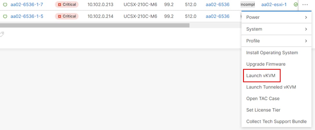
Note: Since the Cisco Custom ISO image will be mapped to the vKVM, it is important to use the standard vKVM and not the Tunneled vKVM and that the Cisco Intersight interface is being run from a subnet that has direct access to the subnet that the CIMC IPs (10.102.0.213 in this example) are provisioned on.
Step 5. Follow the prompts to ignore certificate workings (if any) and launch the HTML5 KVM console.
Step 6. Repeat steps 1 - 5 to launch the HTML5 KVM console for all the ESXi servers.
Set up VMware ESXi Installation
Procedure 1. Prepare the Server for the OS Installation
Note: Follow these steps on each ESXi host.
Step 1. In the KVM window, click Virtual Media > vKVM-Mapped vDVD.
Step 2. Browse and select the ESXi installer ISO image file downloaded in the last in Procedure 1 above (VMware-ESXi-7.0.3d-19482537-Custom-Cisco-4.2.2-a).
Step 3. Click Map Drive.
Step 4. Select Power > Reset System and Confirm to reboot the Server if the server is showing shell prompt. If the server is shutdown, select Power > Power On System.
Step 5. Monitor the server boot process in the KVM. The server should find the boot LUNs and begin to load the ESXi installer.
Note: If the ESXi installer fails to load because the software certificates cannot be validated, reset the server, and when prompted, press F2 to go into BIOS and set the system time and date to current. The ESXi installer should load properly.
Procedure 1. Install VMware ESXi onto the bootable LUN of the UCS Servers
Note: Follow these steps on each host.
Step 1. After the ESXi installer is finished loading (from the last step), press Enter to continue with the installation.
Step 2. Read and accept the end-user license agreement (EULA). Press F11 to accept and continue.
Note: It may be necessary to map function keys as User Defined Macros under the Macros menu in the KVM console.
Step 3. Select the NetApp boot LUN that was previously set up as the installation disk for ESXi and press Enter to continue with the installation.
Step 4. Select the appropriate keyboard layout and press Enter.
Step 5. Enter and confirm the root password and press Enter.
Step 6. The installer issues a warning that the selected disk will be repartitioned. Press F11 to continue with the installation.
Step 7. After the installation is complete, press Enter to reboot the server. The ISO will be unmapped automatically.
Set up Management Networking for ESXi Hosts
Procedure 1. Add the Management Network for each VMware Host
Note: This is required for managing the host. To configure ESXi host with access to the management network, follow these steps on each ESXi host.
Step 1. After the server has finished rebooting, in the UCS KVM console, press F2 to customize VMware ESXi.
Step 2. Log in as root, enter the password set during installation, and press Enter to log in.
Step 3. Use the down arrow key to select Troubleshooting Options and press Enter.
Step 4. Select Enable ESXi Shell and press Enter.
Step 5. Select Enable SSH and press Enter.
Step 6. Press Esc to exit the Troubleshooting Options menu.
Step 7. Select the Configure Management Network option and press Enter.
Step 8. Select Network Adapters and press Enter. Ensure the vmnic numbers align with the numbers under the Hardware Label (for example, vmnic0 and 00-vSwitch0-A). If these numbers do not align, note which vmnics are assigned to which vNICs (indicated under Hardware Label).
Note: In previous FlexPod CVDs, vmnic1 was selected at this stage as the second adapter in vSwitch0. It is important not to select vmnic1 at this stage. If using the Ansible configuration, if vmnic1 is selected here, the Ansible playbook will fail.
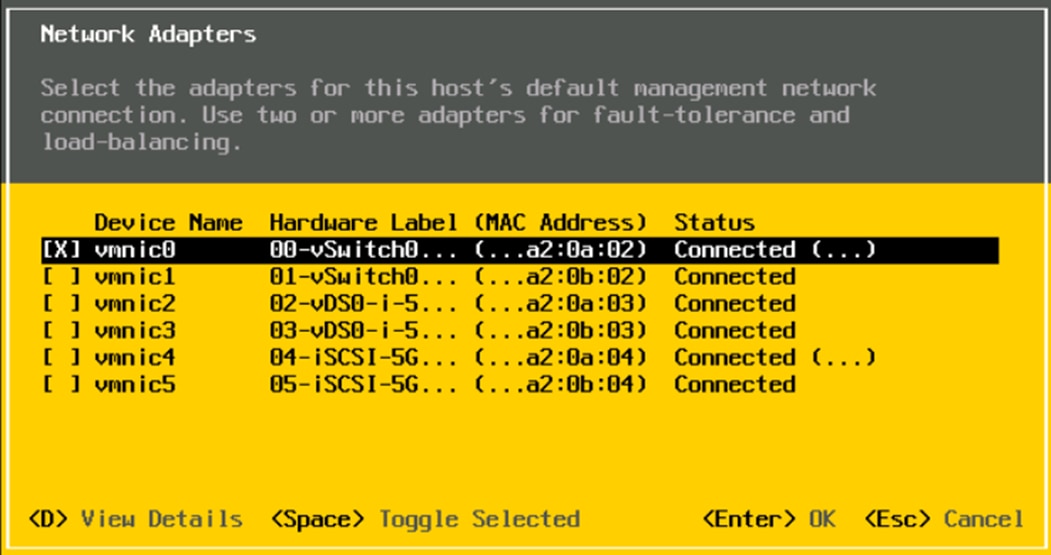
Step 9. Press Enter.
Note: In the UCS Configuration portion of this document, the IB-MGMT VLAN was set as the native VLAN on the 00-vSwitch0-A and 01-vSwitch0-B vNICs. Because of this, the IB-MGMT VLAN should not be set here and should remain Not set.
Step 10. Select IPv4 Configuration and press Enter.
Note: When using DHCP to set the ESXi host networking configuration, setting up a manual IP address is not required.
Step 11. Select the Set static IPv4 address and network configuration option by using the arrow keys and space bar.
Step 12. Under IPv4 Address, enter the IP address for managing the ESXi host.
Step 13. Under Subnet Mask, enter the subnet mask.
Step 14. Under Default Gateway, enter the default gateway.
Step 15. Press Enter to accept the changes to the IP configuration.
Step 16. Select the IPv6 Configuration option and press Enter.
Step 17. Using the spacebar, select Disable IPv6 (restart required) and press Enter.
Step 18. Select the DNS Configuration option and press Enter.
Note: If the IP address is configured manually, the DNS information must be provided.
Step 19. Using the spacebar, select Use the following DNS server addresses and hostname:
● Under Primary DNS Server, enter the IP address of the primary DNS server.
● Optional: Under Alternate DNS Server, enter the IP address of the secondary DNS server.
● Under Hostname, enter the fully qualified domain name (FQDN) for the ESXi host.
● Press Enter to accept the changes to the DNS configuration.
● Press Esc to exit the Configure Management Network submenu.
● Press Y to confirm the changes and reboot the ESXi host.
Procedure 2. (Optional) Reset VMware ESXi Host VMkernel Port MAC Address
Note: By default, the MAC address of the management VMkernel port vmk0 is the same as the MAC address of the Ethernet port it is placed on. If the ESXi host’s boot LUN is remapped to a different server with different MAC addresses, a MAC address conflict will exist because vmk0 will retain the assigned MAC address unless the ESXi System Configuration is reset.
Step 1. From the ESXi console menu main screen, select Macros > Static Macros > Ctrl + Alt + F’s > Ctrl + Alt + F1 to access the VMware console command line interface.
Step 2. Log in as root.
Step 3. Type “esxcfg-vmknic –l” to get a detailed listing of interface vmk0. vmk0 should be a part of the “Management Network” port group. Note the IP address and netmask of vmk0.
Step 4. To remove vmk0, type esxcfg-vmknic –d “Management Network”.
Step 5. To re-add vmk0 with a random MAC address, type esxcfg-vmknic –a –i <vmk0-ip> -n <vmk0-netmask> “Management Network”.
Step 6. Verify vmk0 has been re-added with a random MAC address by typing esxcfg-vmknic –l.
Step 7. Tag vmk0 as the management interface by typing esxcli network ip interface tag add -i vmk0 -t Management.
Step 8. When vmk0 was re-added, if a message pops up saying vmk1 was marked as the management interface, type esxcli network ip interface tag remove -i vmk1 -t Management.
Step 9. Press Ctrl-D to log out of the ESXi console.
Step 10. Select Macros > Static Macros > Ctrl + Alt + F’s > Ctrl + Alt + F2 to return to the VMware ESXi menu.
Install Cisco VIC Drivers and NetApp NFS Plug-in for VAAI
Procedure 1. Download Drivers to the Management Workstation
Step 1. Download and extract where necessary the following drivers to the Management Workstation
● VMware ESXi 7.0 nfnic 5.0.0.34 Driver for Cisco VIC Adapters – Cisco-nfnic_5.0.0.34-1OEM.700.1.0.15843807_19966277.zip – extracted from the downloaded zip
● VMware ESXi 7.0 lsi_mr3 7.720.04.00-1OEM SAS Driver for Broadcom Megaraid 12Gbps - Broadcom-lsi-mr3_7.720.04.00-1OEM.700.1.0.15843807_19476191.zip – extracted from the downloaded zip
● NetApp NFS Plug-in for VMware VAAI 2.0 – NetAppNasPluginV2.0.zip
Note: Consult the Cisco UCS Hardware Compatibility List and the NetApp Interoperability Matrix Tool to determine latest supported combinations of firmware and software.
Procedure 2. Install VMware Drivers and the NetApp NFS Plug-in for VMware VAAI on the ESXi hosts and Setup for NVMe
Step 1. Using an SCP program, copy the two bundles referenced above to the /tmp directory on each ESXi host.
Step 2. SSH to each VMware ESXi host and log in as root.
Step 3. Run the following commands on each host:
esxcli software component apply -d /tmp/Cisco-nfnic_5.0.0.34-1OEM.700.1.0.15843807_19966277.zip
esxcli software component apply -d /tmp/Broadcom-lsi-mr3_7.720.04.00-1OEM.700.1.0.15843807_19476191.zip
esxcli software vib install -d /tmp/NetAppNasPluginV2.0.zip
esxcfg-advcfg -s 0 /Misc/HppManageDegradedPaths
reboot
Step 4. After reboot, SSH back into each host and use the following commands to ensure the correct version are installed:
esxcli software component list | grep nfnic
esxcli software component list | grep lsi-mr3
esxcli software vib list | grep NetApp
esxcfg-advcfg -g /Misc/HppManageDegradedPaths
FlexPod VMware ESXi Manual Configuration
FlexPod VMware ESXi Configuration for the first ESXi Host
Procedure 1. Log into the First ESXi Host using the VMware Host Client
Step 1. Open a web browser and navigate to the first ESXi server’s management IP address.
Step 2. Enter root as the User name.
Step 3. Enter the <root password>.
Step 4. Click Log into connect.
Step 5. Decide whether to join the VMware Customer Experience Improvement Program or not and click OK.
Procedure 2. Set Up iSCSI VMkernel Ports and Virtual Switch (required only for iSCSI boot configuration)
Note: This configuration section only applies to iSCSI ESXi hosts.
Step 1. From the Web Navigator, click Networking.
Step 2. In the center pane, select the Virtual switches tab.
Step 3. Highlight the iScsiBootvSwitch line.
Step 4. Click Edit settings.
Step 5. Change the MTU to 9000.
Step 6. Click Save to save the changes to iScsiBootvSwitch.
Step 7. Select Add standard virtual switch.
Step 8. Name the switch vSwitch1.
Step 9. Change the MTU to 9000.
Step 10. From the drop-down list select vmnic5 for Uplink 1.
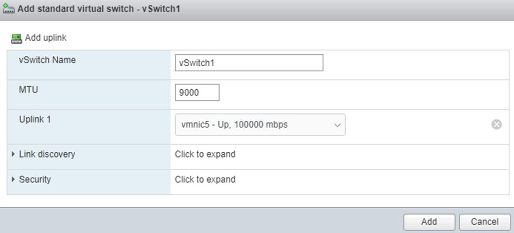
Step 11. Select Add to add vSwitch1.
Step 12. In the center pane, select the VMkernel NICs tab.
Step 13. Highlight the iScsiBootPG line.
Step 14. Click Edit settings.
Step 15. Change the MTU to 9000.
Step 16. Expand IPv4 Settings and enter a unique IP address in the Infra-iSCSI-A subnet but outside of the Cisco Intersight iSCSI-IP-Pool-A.
Note: It is recommended to enter a unique IP address for this VMkernel port to avoid any issues related to IP Pool reassignments in Cisco UCS.
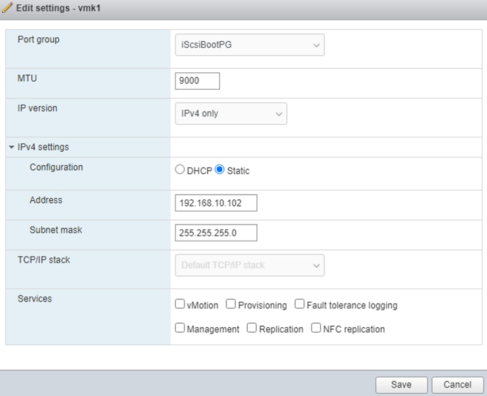
Step 17. Click Save to save the changes to iScsiBootPG VMkernel NIC.
Step 18. Select Add VMkernel NIC.
Step 19. For New port group, enter iScsiBootPG-B.
Step 20. For Virtual switch, from the drop-down list select vSwitch1.
Step 21. Change the MTU to 9000.
Step 22. For IPv4 settings, select Static.
Step 23. Expand IPv4 Settings and enter a unique IP address and Subnet mask in the Infra-iSCSI-B subnet but outside of the Cisco UCS iSCSI-IP-Pool-B.
Step 24. Click Create to complete creating the VMkernel NIC.
Step 25. In the center pane, select the Port groups tab.
Step 26. Highlight the iScsiBootPG line.
Step 27. Click Edit settings.
Step 28. Change the Name to iScsiBootPG-A.
Step 29. Click Save to complete editing the port group name.
Step 30. On the left select Storage, then in the center pane select the Adapters tab.
Step 31. Select Software iSCSI to configure software iSCSI for the host.
Step 32. In the Configure iSCSI window, under Dynamic targets, click Add dynamic target.
Step 33. Select Click to add address and enter the IP address of iscsi-lif-01a from Infra-SVM. Press Enter.
Step 34. Repeat steps 32-33 to add the IP addresses for iscsi-lif-02a, iscsi-lif-01b, and iscsi-lif-02b.
Step 35. Click Save configuration.
Step 36. Click Software iSCSI again open configuration window for iSCSI software adapter.
Step 37. Verify that four static targets and four dynamic targets are listed for the host.
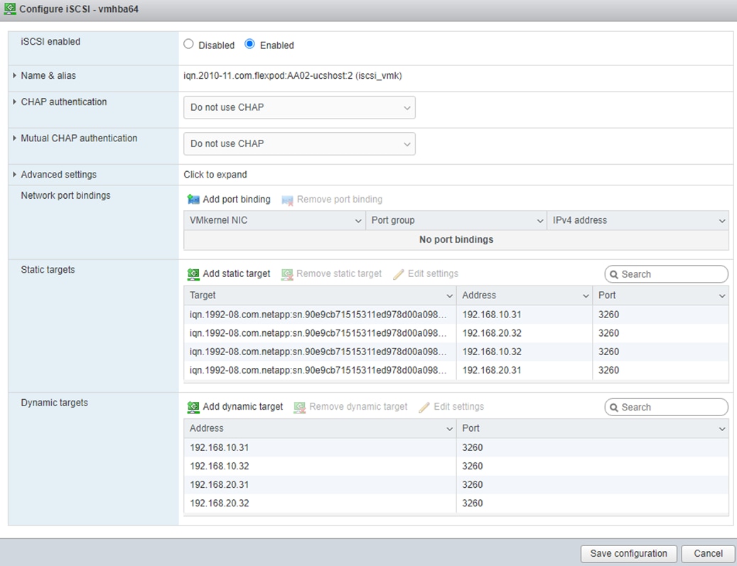
Step 38. Click Cancel to close the window.
Procedure 3. Set Up VMkernel Ports and Virtual Switch
Step 1. From the Host Client Navigator, select Networking.
Step 2. In the center pane, select the Virtual switches tab.
Step 3. Highlight the vSwitch0 line.
Step 4. Click Edit settings.
Step 5. Change the MTU to 9000.
Step 6. Click Add uplink.
Step 7. If vmnic1 is not selected for Uplink 2, then use the pulldown to select vmnic1.
Step 8. Expand NIC teaming.
Step 9. In the Failover order section, if vmnic1 does not have a status of Active, select vmnic1 and click Mark active.
Step 10. Verify that vmnic1 now has a status of Active.
Step 11. Click Save.
Step 12. Select Networking, then select the Port groups tab.
Step 13. In the center pane, right-click VM Network and select Edit settings.
Step 14. Name the port group IB-MGMT Network and leave the VLAN ID set to 0.
Note: In the UCS Configuration portion of this document, the IB-MGMT VLAN was set as the native VLAN on the 00-vSwitch0-A and 01-vSwitch0-B vNICs. Because of this, the IB-MGMT VLAN should stay set to 0.
Step 15. Click Save to finalize the edits for the IB-MGMT Network port group.
Step 16. At the top, select the Port groups tab.
Step 17. In the center pane, select Add port group.
Step 18. Name the port group OOB-MGMT Network and set the VLAN ID to <oob-mgmt-vlan-id> (for example, 1020).
Step 19. Make sure Virtual switch vSwitch0 is selected and click Add to add the OOB-MGMT Network port group.
Step 20. At the top, select the VMkernel NICs tab.
Step 21. Click Add VMkernel NIC.
Step 22. For New port group, enter VMkernel-Infra-NFS.
Step 23. For Virtual switch, select vSwitch0.
Step 24. Enter <infra-nfs-vlan-id> (for example, 3050) for the VLAN ID.
Step 25. Change the MTU to 9000.
Step 26. Select Static IPv4 settings and expand IPv4 settings.
Step 27. Enter the NFS IP address and netmask for this ESXi host.
Step 28. Leave TCP/IP stack set at Default TCP/IP stack and do not select any of the Services.
Step 29. Click Create.
Step 30. Select the Virtual Switches tab, then vSwitch0. The properties for vSwitch0 should be similar to the following screenshot:
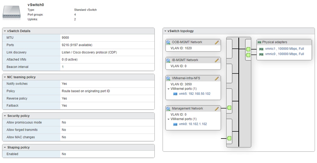
Step 1. From the Web Navigator, select Storage.
Step 2. In the center pane, select the Datastores tab.
Step 3. In the center pane, select New Datastore to add a new datastore.
Step 4. In the New datastore popup, select Mount NFS datastore and click Next.
Step 5. Enter infra_datastore for the datastore name and IP address of the NetApp nfs-lif-02 LIF for the NFS server. Enter /infra_datastore for the NFS share. Select the NFS version. Click Next.
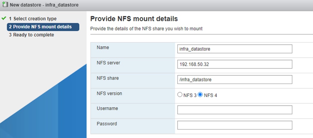
Step 6. Review information and click Finish. The datastore should now appear in the datastore list.
Step 7. In the center pane, select New Datastore to add a new datastore.
Step 8. In the New datastore popup, select Mount NFS datastore and click Next.
Step 9. Enter infra_swap for the datastore name and IP address of the NetApp nfs-lif-01 LIF for the NFS server. Enter /infra_swap for the NFS share. Select the NFS version. Click Next.
Step 10. Click Finish. The datastore should now appear in the datastore list.
Step 11. In the center pane, select New Datastore to add a new datastore.
Step 12. In the New datastore popup, select Mount NFS datastore and click Next.
Step 13. Enter vCLS for the datastore name and IP address of the NetApp nfs-lif-01 LIF for the NFS server. Enter /vCLS for the NFS share. Select the NFS version. Click Next.
Step 14. Click Finish. The datastore should now appear in the datastore list.
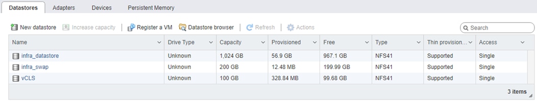
Procedure 5. Configure NTP Servers
Step 1. From the Web Navigator, select Manage.
Step 2. In the center pane, click System > Time & date.
Step 3. Click Edit NTP Settings.
Step 4. Select Use Network Time Protocol (enable NTP client).
Step 5. Use the drop-down list to select Start and stop with host.
Step 6. Enter the NTP server IP addresses in the NTP servers.
Note: Use the IP addresses of the In-Band MGMT NTP Distribution Interfaces configured in the Nexus switches.
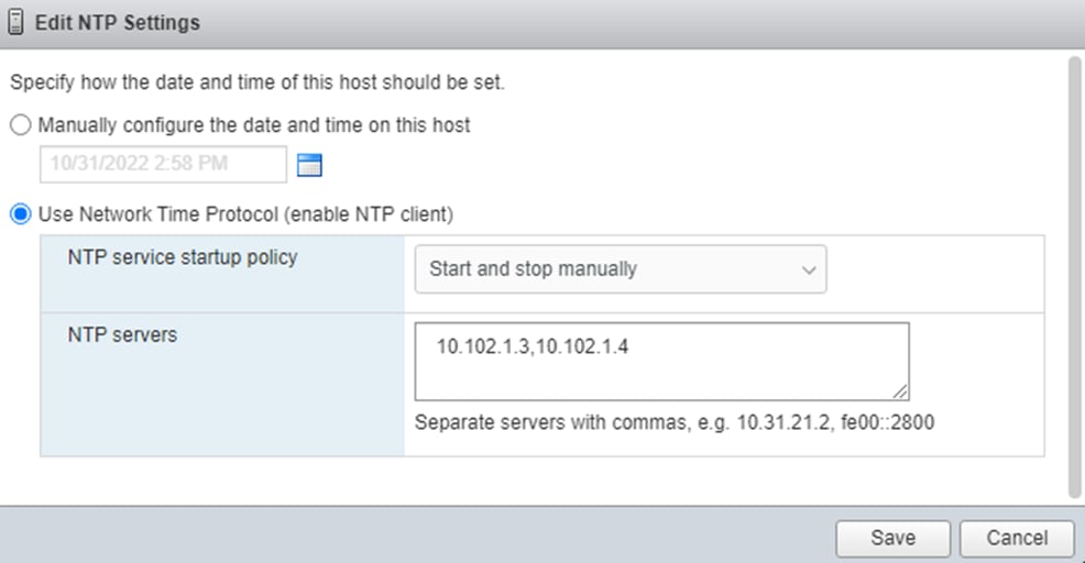
Step 7. Click Save to save the configuration changes.
Step 8. Select the Services tab.
Step 9. Right-click ntpd and click Start.
Step 10. System > Time & date should now show “Running” for the NTP service status.
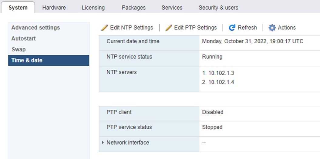
Procedure 6. Configure Host Power Policy on the First ESXi Host
Note: Implementation of this policy is recommended in Performance Tuning Guide for Cisco UCS M6 Servers: https://www.cisco.com/c/en/us/products/collateral/servers-unified-computing/ucs-b-series-blade-servers/performance-tuning-guide-ucs-m6-servers.html for maximum VMware ESXi performance. This policy can be adjusted based on customer requirements.
Step 1. From the Web Navigator, click Manage.
Step 2. In the center pane, click Hardware > Power Management.
Step 3. Click Change policy.
Step 4. Select High performance and click OK.
VMware vCenter 7.0U3h
The procedures in the following sections provide detailed instructions for installing the VMware vCenter 7.0U3h Server Appliance in a FlexPod environment.
Procedure 1. Download vCenter 7.0U3h from VMware
Step 1. Click this link: https://customerconnect.vmware.com/downloads/details?downloadGroup=VC70U3H&productId=974&rPId=95488 and download the VMware-VCSA-all-7.0.3-20395099.iso.
Step 2. You will need a VMware user id and password on vmware.com to download this software.
Procedure 2. Install the VMware vCenter Server Appliance
Note: The VCSA deployment consists of 2 stages: installation and configuration.
Step 1. Locate and copy the VMware-VCSA-all-7.0.3-20395099.iso file to the desktop of the management workstation. This ISO is for the VMware vSphere 7.0 U3 vCenter Server Appliance.
Step 2. Mount the ISO image as a disk on the management workstation. (For example, with the Mount command in Windows Server 2012 and above).
Step 3. In the mounted disk directory, navigate to the vcsa-ui-installer > win32 directory and double-click installer.exe. The vCenter Server Appliance Installer wizard appears.
Step 4. Click Install to start the vCenter Server Appliance deployment wizard.
Step 5. Click NEXT in the Introduction section.
Step 6. Read and accept the license agreement and click NEXT.
Step 7. In the “vCenter Server deployment target” window, enter the FQDN or IP address of the destination host, User name and Password. Click NEXT.
Note: Installation of vCenter on a separate existing management infrastructure vCenter is recommended. If a separate management infrastructure is not available, customers can choose the recently configured first ESXi host as an installation target. The recently configured ESXi host is shown in this deployment.
Step 8. Click YES to accept the certificate.
Step 9. Enter the Appliance VM name and password details shown in the “Set up vCenter Server VM” section. Click NEXT.
Step 10. In the “Select deployment size” section, select the Deployment size and Storage size. For example, select “Small” and “Default.” Click NEXT.
Step 11. Select the datastore (for example, infra_datastore) for storage. Click NEXT.
Step 12. In the Network Settings section, configure the following settings:
a. Select a Network: (for example, IB-MGMT Network)
Note: When the vCenter is running on the FlexPod, it is important that the vCenter VM stay on the IB-MGMT Network on vSwitch0 and not moved to a vDS. If vCenter is moved to a vDS and the virtual environment is completely shut down and then brought back up, trying to bring up vCenter on a different host than the one it was running on before the shutdown will cause problems with the network connectivity. With the vDS, for a virtual machine to move from one host to another, vCenter must be up and running to coordinate the move of the virtual ports on the vDS. If vCenter is down, the port move on the vDS cannot occur correctly. Moving vCenter to a different host on vSwitch0 does not require vCenter to already be up and running.
b. IP version: IPV4
c. IP assignment: static
d. FQDN: <vcenter-fqdn>
e. IP address: <vcenter-ip>
f. Subnet mask or prefix length: <vcenter-subnet-mask>
g. Default gateway: <vcenter-gateway>
h. DNS Servers: <dns-server1>,<dns-server2>
Step 13. Click NEXT.
Step 14. Review all values and click FINISH to complete the installation.
Note: The vCenter Server appliance installation will take a few minutes to complete.
Step 15. When Stage 1, Deploy vCenter Server, is complete, Click CONTINUE to proceed with stage 2.
Step 16. Click NEXT.
Step 17. In the vCenter Server configuration window, configure these settings:
a. Time Synchronization Mode: Synchronize time with NTP servers.
b. NTP Servers: NTP server IP addresses from IB-MGMT VLAN
c. SSH access: Enabled.
Step 18. Click NEXT.
Step 19. Complete the SSO configuration as shown below (or according to your organization’s security policies):
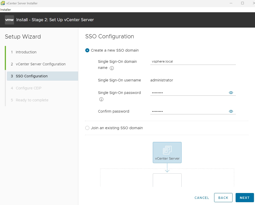
Step 20. Click NEXT.
Step 21. Decide whether to join VMware’s Customer Experience Improvement Program (CEIP).
Step 22. Click NEXT.
Step 23. Review the configuration and click FINISH.
Step 24. Click OK.
Note: vCenter Server setup will take a few minutes to complete and Install – Stage 2 with show Complete.
Step 25. Click CLOSE. Eject or unmount the VCSA installer ISO.
Procedure 3. Verify vCenter CPU Settings
Note: If a vCenter deployment size of Small or larger was selected in the vCenter setup, it is possible that the VCSA’s CPU setup does not match the Cisco UCS server CPU hardware configuration. Cisco UCS X210c M6 and B200 M6 servers are 2-socket servers. During this validation, the Small deployment size was selected and vCenter was setup for a 4-socket server. This setup can cause issues in the VMware ESXi cluster Admission Control.
Step 1. Open a web browser on the management workstation and navigate to the vCenter or ESXi server where the vCenter appliance was deployed and login.
Step 2. Click the vCenter VM, right-click and click Edit settings.
Step 3. In the Edit settings window, expand CPU and check the value of Sockets.
Step 4. If the number of Sockets match the server configuration, click Cancel.
Step 5. If the number of Sockets does not match the server configuration, it will need to be adjusted:
Step 6. Right-click the vCenter VM and click Guest OS > Shut down. Click Yes on the confirmation.
Step 7. When vCenter is shut down, right-click the vCenter VM and click Edit settings.
Step 8. In the Edit settings window, expand CPU and change the Cores per Socket value to make the Sockets value equal to the server configuration.
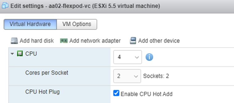
Step 9. Click Save.
Step 10. Right-click the vCenter VM and click Power > Power on. Wait approximately 10 minutes for vCenter to come up.
Procedure 4. Setup VMware vCenter Server
Step 1. Using a web browser, navigate to https://<vcenter-ip-address>:5480. Navigate security screens.
Step 2. Log into the VMware vCenter Server Management interface as root with the root password set in the vCenter installation.
Step 3. In the menu on the left, click Time.
Step 4. Click EDIT to the right of Time zone.
Step 5. Select the appropriate Time zone and click SAVE.
Step 6. In the menu on the left select Administration.
Step 7. According to your Security Policy, adjust the settings for the root user and password.
Step 8. In the menu on the left click Update.
Step 9. Follow the prompts to stage and install any available vCenter updates.
Step 10. In the upper right-hand corner of the screen, click root > Logout to logout of the Appliance Management interface.
Step 11. Using a web browser, navigate to https://<vcenter-fqdn> and navigate through security screens.
Note: With VMware vCenter 7.0 and above, you must use the vCenter FQDN.
Step 12. Select LAUNCH VSPHERE CLIENT (HTML5).
The VMware vSphere HTML5 Client is the only option in vSphere 7. All the old clients have been deprecated.
Step 13. Log in using the Single Sign-On username (administrator@vsphere.local) and password created during the vCenter installation. Dismiss the Licensing warning.
Procedure 5. Add AD User Authentication to vCenter (Optional)
Step 1. In the AD Infrastructure, using the Active Directory Users and Computers tool, setup a Domain Administrator user with a user name such as flexadmin (FlexPod Admin).
Step 2. Connect to https://<vcenter-fqdn> and select LAUNCH VSPHERE CLIENT (HTML5).
Step 3. Log in as administrator@vsphere.local (or the SSO user set up in vCenter installation) with the corresponding password.
Step 4. Under the top-level menu, click Administration. In the list on the left, under Single Sign On, select Configuration.
Step 5. In the center pane, under Configuration, select the Identity Provider tab.
Step 6. In the list under Type, select Active Directory Domain.
Step 7. Click JOIN AD.
Step 8. Fill in the AD domain name, the Administrator user, and the domain Administrator password. Do not fill in an Organizational unit. Click JOIN.
Step 9. Click Acknowledge.
Step 10. In the list on the left under Deployment, click System Configuration. Select the radio button to select the vCenter, then click REBOOT NODE.
Step 11. Input a reboot reason and click REBOOT. The reboot will take approximately 10 minutes for full vCenter initialization.
Step 12. Log back into the vCenter vSphere HTML5 Client as Administrator@vsphere.local.
Step 13. Under the top-level menu, click Administration. In the list on the left, under Single Sign On, click Configuration.
Step 14. In the center pane, under Configuration, click the Identity Provider tab. Under Type, select Identity Sources. Click ADD.
Step 15. Make sure Active Directory (Integrated Windows Authentication) is selected, your Windows Domain name is listed, and Use machine account is selected. Click ADD.
Step 16. In the list select the Active Directory (Integrated Windows Authentication) Identity source type. If desired, select SET AS DEFAULT and click OK.
Step 17. On the left under Access Control, select Global Permissions.
Step 18. In the center pane, click the ADD to add a Global Permission.
Step 19. In the Add Permission window, select your AD domain for the Domain.
Step 20. On the User/Group line, enter either the FlexPod Admin username or the Domain Admins group. Leave the Role set to Administrator. Check the box for Propagate to children.
Note: The FlexPod Admin user was created in the Domain Admins group. The selection here depends on whether the FlexPod Admin user will be the only user used in this FlexPod or if additional users will be added later. By selecting the Domain Admins group, any user placed in that AD Domain group will be able to login to vCenter as an Administrator.
Step 21. Click OK to add the selected User or Group. The user or group should now appear in the Global Permissions list with the Administrator role.
Step 22. Log out and log back into the vCenter HTML5 Client as the FlexPod Admin user. You will need to add the domain name to the user, for example, flexadmin@domain.
vCenter - Initial Configuration
Procedure 1. Configure vCenter
Step 1. In the center pane, click ACTIONS > New Datacenter.
Step 2. Type FlexPod-DC in the Datacenter name field.
Step 3. Click OK.
Step 4. Expand the vCenter.
Step 5. Right-click the datacenter FlexPod-DC in the list in the left pane. Click New Cluster…
Step 6. Provide a name for the cluster (for example, FlexPod-MGMT).
Step 7. Turn on DRS and vSphere HA. Do not turn on vSAN.
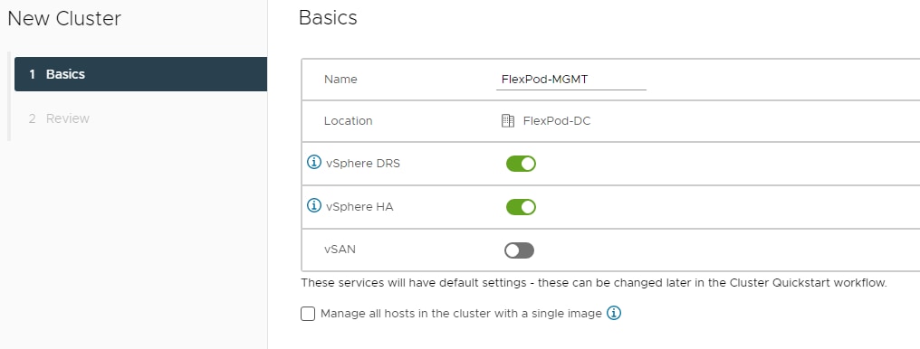
Step 8. Click NEXT and then click FINISH to create the new cluster.
Step 9. Right-click the cluster and click Settings.
Step 10. Click Configuration > General in the list located on the left and click EDIT to the right of General.
Step 11. Select Datastore specified by host for the Swap file location and click OK.
Step 12. Right-click the cluster and select Add Hosts.
Step 13. In the IP address or FQDN field, enter either the IP address or the FQDN of the first VMware ESXi host. Enter root as the Username and the root password.
Step 14. For all other configured ESXi hosts, click ADD HOST. Enter either the IP address or the FQDN of the host being added. You can either select “Use the same credentials for all hosts” or enter root and the host root password. Repeat this to add all hosts.
Step 15. Click NEXT.
Step 16. In the Security Alert window, select the host(s) and click OK.
Step 17. Verify the Host summary information and click NEXT.
Step 18. Ignore warnings about the host being moved to Maintenance Mode and click FINISH to complete adding the host(s) to the cluster.
Note: The added ESXi host(s) will have Warnings that the ESXi Shell and SSH have been enabled. These warnings can be suppressed. The host will also have a TPM Encryption Key Recovery alert that can be reset to green.
Step 19. For any hosts that are in Maintenance Mode, right-click the host and select Maintenance Mode > Exit Maintenance Mode.
Step 20. In the list, right-click the added ESXi host(s) and click Settings.
Step 21. In the center pane under Virtual Machines, click Swap File location.
Step 22. On the right, click EDIT.
Step 23. Select infra_swap and click OK.
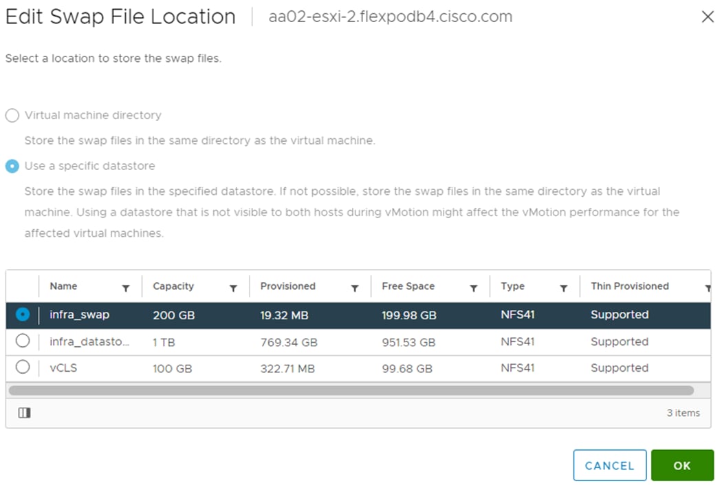
Step 24. Repeat steps 20-23 to set the swap file location for each configured ESXi host.
Step 25. Right-click the cluster and select Settings. In the center pane under vSphere Cluster Services, select Datastores. In the center of the window, click ADD. Select the vCLS datastore and click ADD.
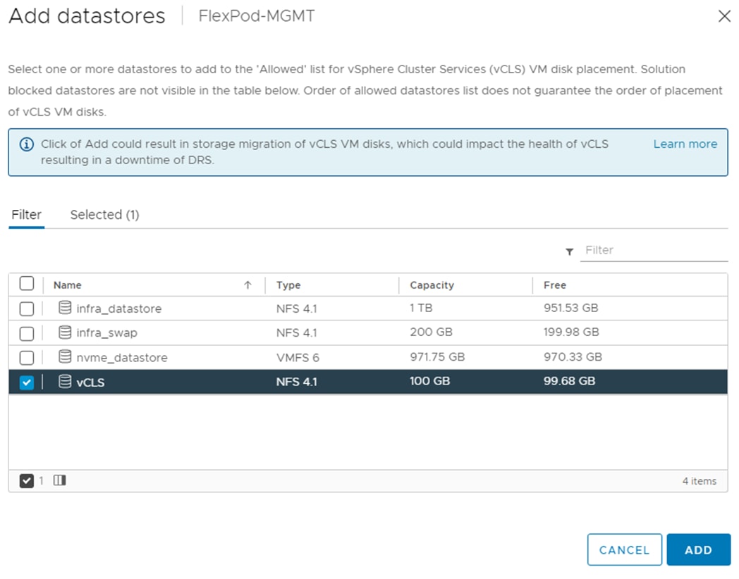
Step 26. Select the first ESXi host. In the center pane under Configure > Storage, click Storage Devices. Make sure the NetApp Fibre Channel Disk LUN 0 or NetApp iSCSI Disk LUN 0 is selected.
Step 27. Click the Paths tab.
Step 28. Ensure that 4 paths appear, two of which should have the status Active (I/O). The output below shows the paths for an iSCSI LUN.
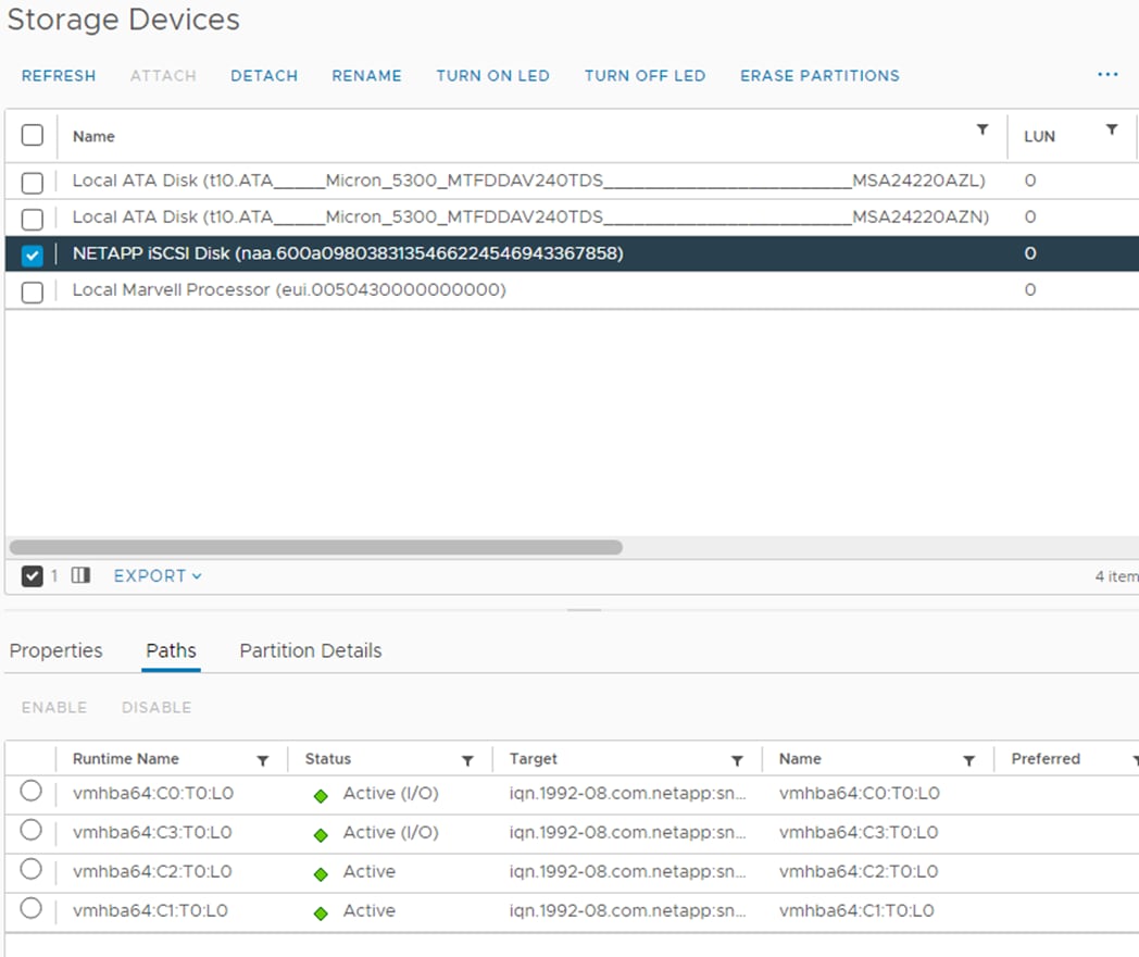
Step 29. Repeat steps 26-28 for all configured ESXi hosts.
FlexPod VMware vSphere Distributed Switch (vDS)
This section provides detailed procedures for setting up VMware vDS in vCenter. Based on the VLAN configuration in Intersight, a vMotion, and a VM-Traffic port group will be added to the vDS. Any additional VLAN-based port groups added to the vDS would require changes in Intersight, the Cisco Nexus 9K switches, and possibly the NetApp storage cluster.
In this document, the infrastructure ESXi management VMkernel ports, the In-Band management interfaces including the vCenter management interface, and the infrastructure NFS VMkernel ports are left on vSwitch0 to facilitate bringing the virtual environment back up in the event it needs to be completely shut down. The vMotion VMkernel ports are provisioned on the vDS to allow for future QoS support. The vMotion port group is also pinned to Cisco UCS fabric B and pinning configuration in vDS ensures consistency across all ESXi hosts.
Procedure 1. Configure the VMware vDS in vCenter
Step 1. After logging into the VMware vSphere HTML5 Client, select Inventory under the top-level menu.
Step 2. Click ![]() , the fourth icon at the top, to go to Networking.
, the fourth icon at the top, to go to Networking.
Step 3. Expand the vCenter and right-click the FlexPod-DC datacenter and click Distributed Switch > New Distributed Switch.
Step 4. Give the Distributed Switch a descriptive name (for example, vDS0) and click NEXT.
Step 5. Make sure version 7.0.3 – ESXi 7.0.3 and later is selected and click NEXT.
Step 6. Change the Number of uplinks to 2. If VMware Network I/O Control is to be used for Quality of Service, leave Network I/O Control Enabled. Otherwise, Disable Network I/O Control. Enter VM-Traffic for the Port group name. Click NEXT.
Step 7. Review the information and click FINISH to complete creating the vDS.
Step 8. Expand the FlexPod-DC datacenter and the newly created vDS. Click the newly created vDS.
Step 9. Right-click the VM-Traffic port group and click Edit Settings.
Step 10. Select VLAN.
Step 11. Select VLAN for VLAN type and enter the VM-Traffic VLAN ID (for example, 1022). Click OK.
Step 12. Right-click the vDS and click Settings > Edit Settings.
Step 13. In the Edit Settings window, click the Advanced tab.
Step 14. Change the MTU to 9000. The Discovery Protocol can optionally be changed to Link Layer Discovery Protocol and the Operation to Both. Click OK.
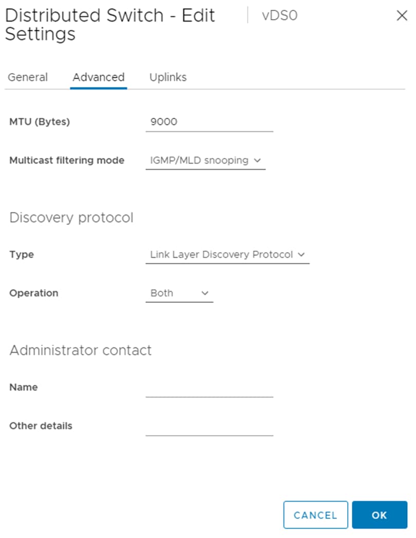
Step 15. To create the vMotion port group, right-click the vDS, select Distributed Port Group > New Distributed Port Group.
Step 16. Enter vMotion as the name and click NEXT.
Step 17. Set the VLAN type to VLAN, enter the VLAN ID used for vMotion (for example, 3000), check the box for Customize default policies configuration, and click NEXT.
Step 18. Leave the Security options set to Reject and click NEXT.
Step 19. Leave the Ingress and Egress traffic shaping options as Disabled and click NEXT.
Step 20. Select Uplink 1 from the list of Active uplinks and click MOVE DOWN twice to place Uplink 1 in the list of Standby uplinks. This will pin all vMotion traffic to UCS Fabric Interconnect B except when a failure occurs.
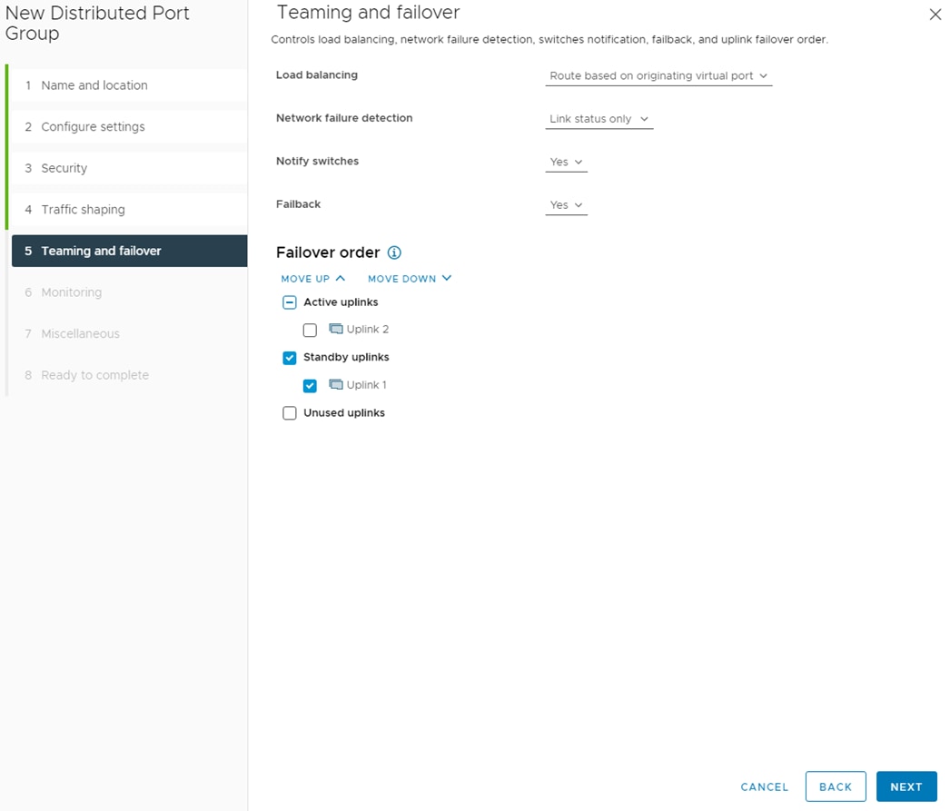
Step 21. Click NEXT.
Step 22. Leave NetFlow disabled and click NEXT.
Step 23. Leave Block all ports set as No and click NEXT.
Step 24. Confirm the options and click FINISH to create the port group.
Step 25. Right-click the vDS and click Add and Manage Hosts.
Step 26. Make sure Add hosts is selected and click NEXT.
Step 27. Click SELECT ALL to select all ESXi hosts. Click NEXT.
Step 28. If all hosts had alignment in the ESXi console screen between vmnic numbers and vNIC numbers, leave Adapters on all hosts selected. To the right of vmnic2, use the pulldown to select Uplink 1. To the right of vmnic3, use the pulldown to select Uplink 2. Click NEXT. If the vmnic numbers and vNIC numbers did not align, select Adapters per host and select vDS uplinks individually on each host.
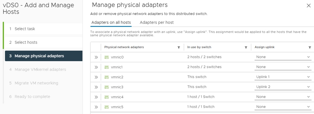
Note: It is important to assign the uplinks as shown above. This allows the port groups to be pinned to the appropriate Cisco UCS Fabric.
Step 29. Do not migrate any VMkernel ports and click NEXT.
Step 30. Do not migrate any virtual machine networking ports. Click NEXT.
Step 31. Click FINISH to complete adding the ESXi host to the vDS.
Step 32. Select Hosts and Clusters and select the first ESXi host. In the center pane, select the Configure tab.
Step 33. In the list under Networking, select VMkernel adapters.
Step 34. Select ADD NETWORKING.
Step 35. In the Add Networking window, ensure that VMkernel Network Adapter is selected and click NEXT.
Step 36. Ensure that Select an existing network is selected and click BROWSE.
Step 37. Select vMotion and click OK.
Step 38. Click NEXT.
Step 39. From the MTU drop-down list, select Custom and ensure the MTU is set to 9000.
Step 40. From the TCP/IP stack drop-down list, select vMotion. Click NEXT.
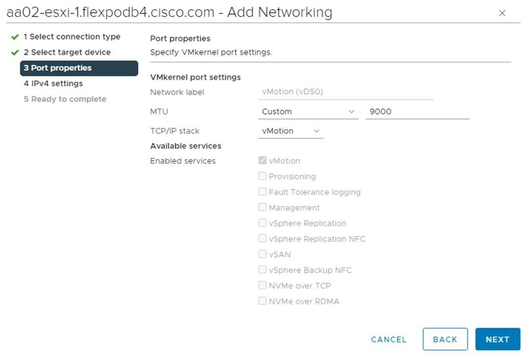
Step 41. Select Use static IPv4 settings and fill in the IPv4 address and Subnet mask for the first ESXi host’s vMotion IPv4 address and Subnet mask. Click NEXT.
Step 42. Review the information and click FINISH to complete adding the vMotion VMkernel port.
Step 43. Repeat steps 32-42 for all other configured ESXi hosts.
Procedure 2. Configure the iSCSI-NVMe-TCP vDS in vCenter (Only if iSCSI-booted Hosts and NVMe-TCP are in Use)
Note: Only execute this procedure if you have iSCSI-booted ESXi hosts in your FlexPod configuration. It is assumed that NVMe-TCP will be used only on iSCSI-booted hosts.
Step 1. After logging into the VMware vSphere HTML5 Client, select Inventory under the top-level menu.
Step 2. Click ![]() , the fourth icon at the top, to go to Networking.
, the fourth icon at the top, to go to Networking.
Step 3. Expand the vCenter and right-click the FlexPod-DC datacenter and click Distributed Switch > New Distributed Switch.
Step 4. Give the Distributed Switch a descriptive name (for example, iSCSI-NVMe-TCP-vDS or iSCSI-vDS) and click NEXT.
Step 5. Make sure version 7.0.3 – ESXi 7.0.3 and later is selected and click NEXT.
Step 6. Change the Number of uplinks to 2. If VMware Network I/O Control is to be used for Quality of Service, leave Network I/O Control Enabled. Otherwise, Disable Network I/O Control. Uncheck “Create a default port group.” Click NEXT.
Step 7. Review the information and click FINISH to complete creating the vDS.
Step 8. Expand the FlexPod-DC datacenter and the newly created vDS. Click the newly created vDS.
Step 9. Right-click the new vDS and click Settings > Edit Settings.
Step 10. In the Edit Settings window, click the Advanced tab.
Step 11. Change the MTU to 9000. The Discovery Protocol can optionally be changed to Link Layer Discovery Protocol and the Operation to Both. Click OK.
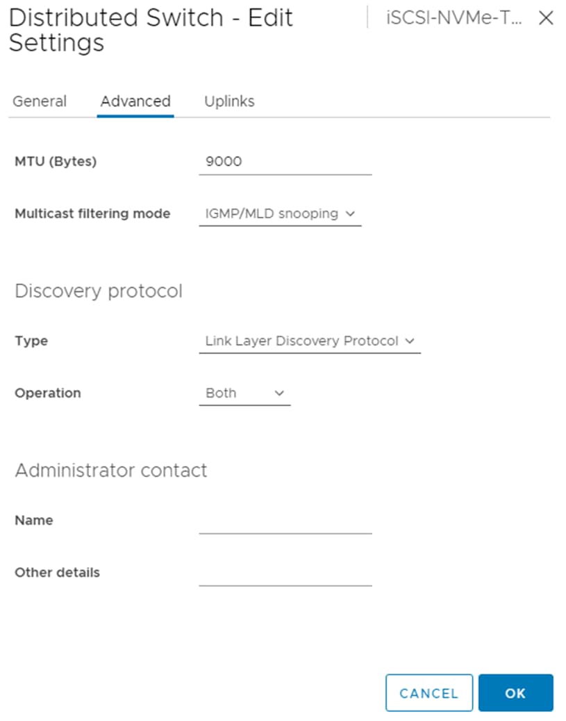
Step 12. To create the Infra-iSCSI-A port group, right-click the vDS, select Distributed Port Group > New Distributed Port Group.
Step 13. Enter Infra-iSCSI-A as the name and click NEXT.
Step 14. Leave the VLAN type set to None, check the box for Customize default policies configuration, and click NEXT.
Step 15. Leave the Security options set to Reject and click NEXT.
Step 16. Leave the Ingress and Egress traffic shaping options as Disabled and click NEXT.
Step 17. Select Uplink 2 from the list of Active uplinks and click MOVE DOWN twice to place Uplink 2 in the list of Unused uplinks. This will pin all Infra-iSCSI-A traffic to UCS Fabric Interconnect A.
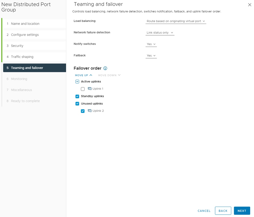
Step 18. Click NEXT.
Step 19. Leave NetFlow disabled and click NEXT.
Step 20. Leave Block all ports set as No and click NEXT.
Step 21. Confirm the options and click FINISH to create the port group.
Step 22. To create the Infra-iSCSI-B port group, right-click the vDS, select Distributed Port Group > New Distributed Port Group.
Step 23. Enter Infra-iSCSI-B as the name and click NEXT.
Step 24. Leave the VLAN type set to None, check the box for Customize default policies configuration, and click NEXT.
Step 25. Leave the Security options set to Reject and click NEXT.
Step 26. Leave the Ingress and Egress traffic shaping options as Disabled and click NEXT.
Step 27. Select Uplink 1 from the list of Active uplinks and click MOVE DOWN three times to place Uplink 1 in the list of Unused uplinks. This will pin all Infra-iSCSI-B traffic to UCS Fabric Interconnect B.
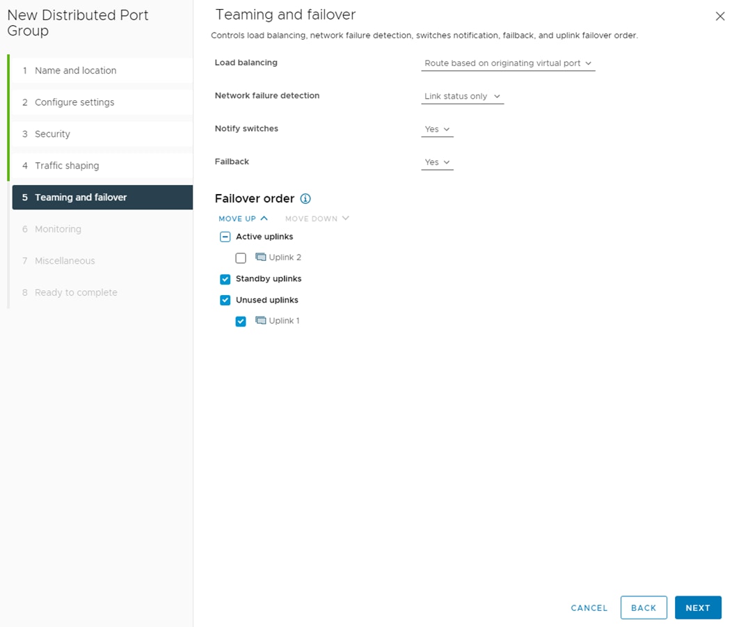
Step 28. Click NEXT.
Step 29. Leave NetFlow disabled and click NEXT.
Step 30. Leave Block all ports set as No and click NEXT.
Step 31. Confirm the options and click FINISH to create the port group.
Step 32. Only execute steps 33-52 if you are implementing NVMe-TCP.
Step 33. To create the Infra-NVMe-TCP-A port group, right-click the vDS, select Distributed Port Group > New Distributed Port Group.
Step 34. Enter Infra-NVMe-TCP-A as the name and click NEXT.
Step 35. Set the VLAN type to VLAN, enter the Infra-NVMe-TCP-A VLAN ID, check the box for Customize default policies configuration, and click NEXT.
Step 36. Leave the Security options set to Reject and click NEXT.
Step 37. Leave the Ingress and Egress traffic shaping options as Disabled and click NEXT.
Step 38. Select Uplink 2 from the list of Active uplinks and click MOVE DOWN twice to place Uplink 2 in the list of Unused uplinks. This will pin all Infra-NVMe-TCP-A traffic to UCS Fabric Interconnect A.
Step 39. Click NEXT.
Step 40. Leave NetFlow disabled and click NEXT.
Step 41. Leave Block all ports set as No and click NEXT.
Step 42. Confirm the options and click FINISH to create the port group.
Step 43. To create the Infra-NVMe-TCP-B port group, right-click the vDS, select Distributed Port Group > New Distributed Port Group.
Step 44. Enter Infra-NVMe-TCP-B as the name and click NEXT.
Step 45. Set the VLAN type to VLAN, enter the Infra-NVMe-TCP-B VLAN ID, check the box for Customize default policies configuration, and click NEXT.
Step 46. Leave the Security options set to Reject and click NEXT.
Step 47. Leave the Ingress and Egress traffic shaping options as Disabled and click NEXT.
Step 48. Select Uplink 1 from the list of Active uplinks and click MOVE DOWN three times to place Uplink 1 in the list of Unused uplinks. This will pin all Infra-NVMe-TCP-B traffic to UCS Fabric Interconnect B.
Step 49. Click NEXT.
Step 50. Leave NetFlow disabled and click NEXT.
Step 51. Leave Block all ports set as No and click NEXT.
Step 52. Confirm the options and click FINISH to create the port group.
Step 53. If you have any configured iSCSI booted hosts, execute the remaining scripts in this procedure.
Step 54. Right-click the iSCSI-NVMe-TCP vDS and click Add and Manage Hosts.
Step 55. Make sure Add hosts is selected and click NEXT.
Step 56. Select all configured iSCSI-booted hosts and click NEXT.
Step 57. If all hosts had alignment in the ESXi console screen between vmnic numbers and vNIC numbers, leave Adapters on all hosts selected. To the right of vmnic5, use the pulldown to select Uplink 2. Click NEXT. If the vmnic numbers and vNIC numbers did not align, select Adapters per host and select vDS uplinks individually on each host.
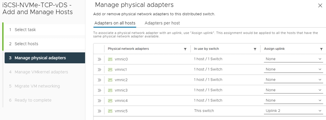
Note: It is important to assign the uplink as shown above. This allows the port groups to be pinned to the appropriate Cisco UCS Fabric and iSCSI network connectivity to be maintained.
Step 58. To the right of vmk2, click ASSIGN PORT GROUP.
Step 59. To the right of Infra-iSCSI-B, click ASSIGN. Click NEXT.
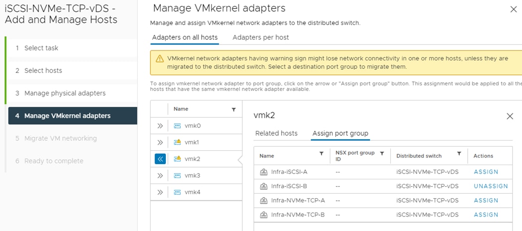
Step 60. Do not migrate any virtual machine networking ports. Click NEXT.
Step 61. Click FINISH to complete adding the ESXi host(s) to the vDS.
Step 62. Select Hosts and Clusters and select the first ESXi host added to the iSCSI-NVMe-TCP-vDS. In the center pane, select the Configure tab.
Step 63. In the list under Networking, select VMkernel switches.
Step 64. Expand Standard Switch: vSwitch1. To the right of vSwitch1, select … > Remove. Click YES to confirm the removal of vSwitch1.
Step 65. Expand Standard Switch: iScsiBootvSwitch. To the right of iScsiBootvSwitch, select … > Remove. Click YES to confirm the removal of iScsiBootvSwitch.
Step 66. To the right of Distributed Switch: iSCSI-NVMe-TCP-vDS, click MANAGE PHYSICAL ADAPTERS.
Step 67. Click the Plus Sign to add an uplink. Select vmnic4 and click OK.
Step 68. Verify that vmnic4 is now Uplink 1 and click OK.
Step 69. In the center pane under Networking, select VMkernel adapters. Click ADD NETWORKING.
Step 70. In the Add Networking window, ensure that VMkernel Network Adapter is selected and click NEXT.
Step 71. Ensure that Select an existing network is selected and click BROWSE.
Step 72. Select Infra-iSCSI-A and click OK.
Step 73. Click NEXT.
Step 74. From the MTU drop-down list, select Custom and ensure the MTU is set to 9000. Click NEXT.
Step 75. Select Use static IPv4 settings and fill in the IPv4 address and Subnet mask for the ESXi host’s Infra-iSCSI-A IPv4 address and Subnet mask. Click NEXT.
Step 76. Review the information and click FINISH to complete adding the Infra-iSCSI-A VMkernel port.
Step 77. Execute the following steps 78-94 only if implementing NVMe-TCP in this FlexPod.
Step 78. In the center pane under Networking, select VMkernel adapters. Click ADD NETWORKING.
Step 79. In the Add Networking window, ensure that VMkernel Network Adapter is selected and click NEXT.
Step 80. Ensure that Select an existing network is selected and click BROWSE.
Step 81. Select Infra-NVMe-TCP-A and click OK.
Step 82. Click NEXT.
Step 83. From the MTU drop-down list, select Custom and ensure the MTU is set to 9000. Leave TCP/IP stack set to Default and select the NVMe over TCP from Enabled services. Click NEXT.
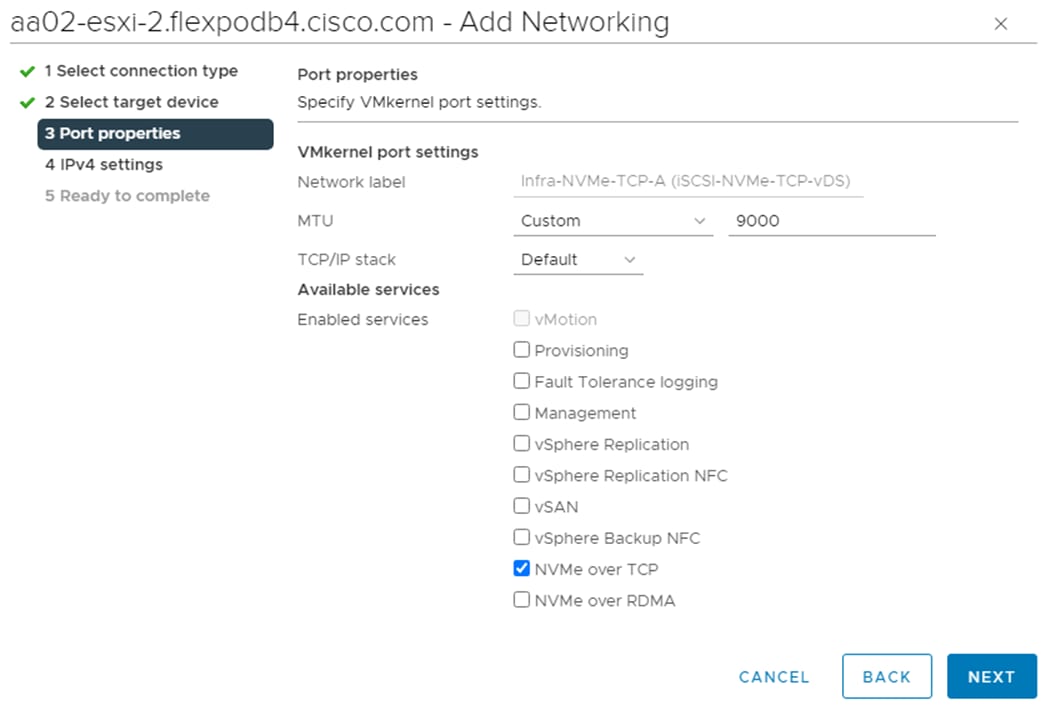
Step 84. Select Use static IPv4 settings and fill in the IPv4 address and Subnet mask for the ESXi host’s Infra-NVMe-TCP-A IPv4 address and Subnet mask. Click NEXT.
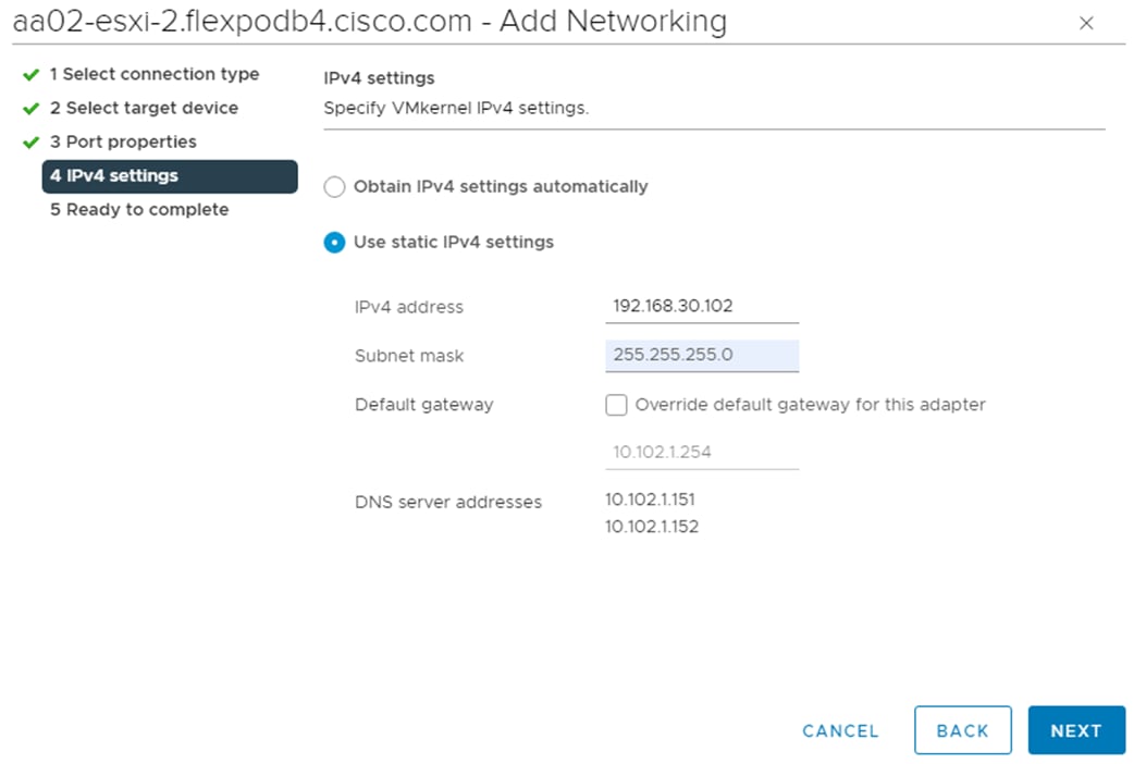
Step 85. Review the information and click FINISH to complete adding the Infra-NVMe-TCP-A VMkernel port.
Step 86. In the center pane under Networking, select VMkernel adapters. Click ADD NETWORKING.
Step 87. In the Add Networking window, ensure that VMkernel Network Adapter is selected and click NEXT.
Step 88. Ensure that Select an existing network is selected and click BROWSE.
Step 89. Select Infra-NVMe-TCP-B and click OK.
Step 90. Click NEXT.
Step 91. From the MTU drop-down list, select Custom and ensure the MTU is set to 9000. Leave TCP/IP stack set to Default and select the NVMe over TCP from Enabled services. Click NEXT.
Step 92. Select Use static IPv4 settings and fill in the IPv4 address and Subnet mask for the ESXi host’s Infra-NVMe-TCP-B IPv4 address and Subnet mask. Click NEXT.
Step 93. Review the information and click FINISH to complete adding the Infra-NVMe-TCP-B VMkernel port.
Step 94. The list of VMkernel adapters should now look similar to the following:
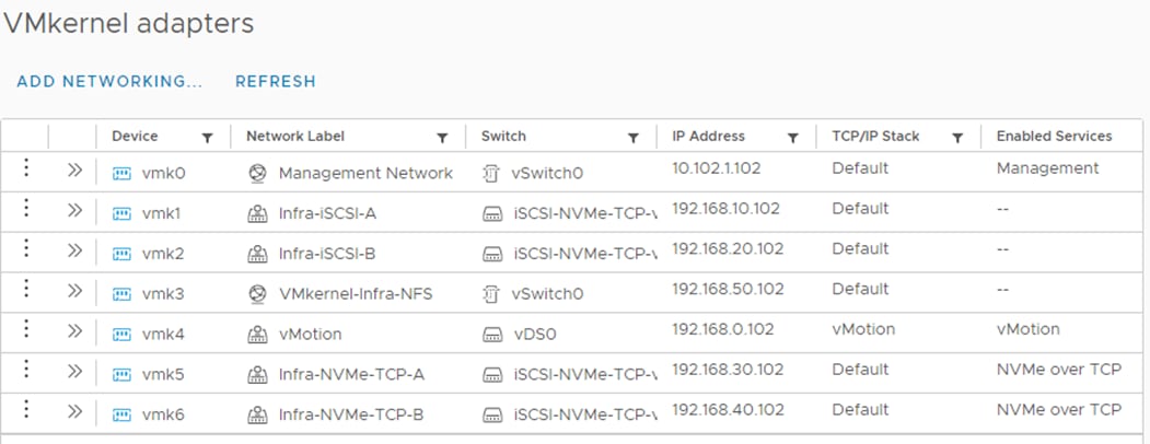
Step 95. Repeat steps 62-94 for all other configured iSCSI-booted ESXi hosts.
Add and Configure VMware ESXi Hosts in vCenter
This procedure details the steps to add and configure an ESXi host in vCenter.
Procedure 1. Add the ESXi Hosts to vCenter
Step 1. From the Home screen in the VMware vCenter HTML5 Interface, click Hosts and Clusters.
Step 2. Right-click the cluster and click Add Hosts.
Step 3. In the IP address or FQDN field, enter either the IP address or the FQDN name of the configured VMware ESXi host. Also enter the user id (root) and associated password. If more than one host is being added, add the corresponding host information, optionally selecting “Use the same credentials for all hosts.” Click NEXT.
Step 4. Select all hosts being added and click OK to accept the thumbprint(s).
Step 5. Review the host details and click NEXT to continue.
Step 6. Review the configuration parameters and click FINISH to add the host(s).
Note: The added ESXi host(s) will be placed in Maintenance Mode and will have Warnings that the ESXi Shell and SSH have been enabled. These warnings can be suppressed. The TPM Encryption Recovery Key Backup Alarm can also be Reset to Green.
Procedure 2. Add iSCSI Configuration (required only for iSCSI-boot configuration)
Step 1. In the vSphere HTML5 Client, under Networking, select the iSCSI-NVMe-TCP-vDS.
Step 2. Right-click the iSCSI-NVMe-TCP vDS and click Add and Manage Hosts.
Step 3. Make sure Add hosts is selected and click NEXT.
Step 4. Select all iSCSI-booted hosts and click NEXT.
Step 5. If all hosts had alignment in the ESXi console screen between vmnic numbers and vNIC numbers, leave Adapters on all hosts selected. To the right of vmnic5, use the pulldown to select Uplink 2. Click NEXT. If the vmnic numbers and vNIC numbers did not align, select Adapters per host and select vDS uplinks individually on each host.
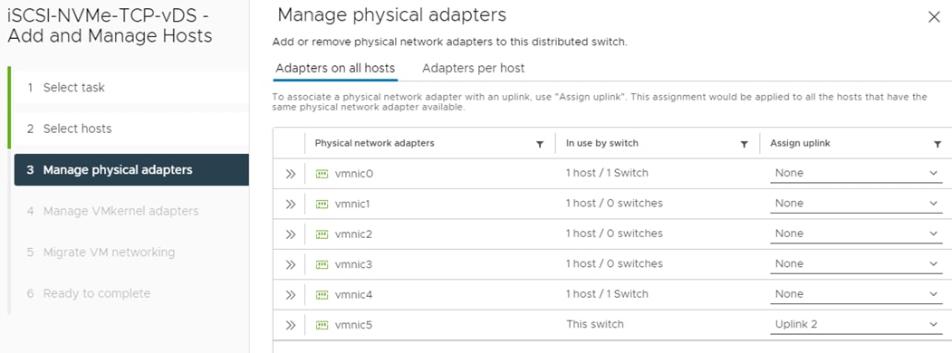
Note: It is important to assign the uplink as shown above. This allows the port groups to be pinned to the appropriate Cisco UCS Fabric and iSCSI network connectivity to be maintained.
Step 6. Do not assign any VMkernel adapters and click NEXT.
Step 7. Do not migrate any virtual machine networking ports. Click NEXT.
Step 8. Click FINISH to complete adding the ESXi host(s) to the vDS.
Step 9. Select Hosts and Clusters and select the first ESXi host added to the iSCSI-NVMe-TCP-vDS. In the center pane, select the Configure tab.
Step 10. In the center pane under Networking, select VMkernel adapters. Click ADD NETWORKING.
Step 11. In the Add Networking window, ensure that VMkernel Network Adapter is selected and click NEXT.
Step 12. Ensure that Select an existing network is selected and click BROWSE.
Step 13. Select Infra-iSCSI-B and click OK.
Step 14. Click NEXT.
Step 15. From the MTU drop-down list, select Custom and ensure the MTU is set to 9000. Click NEXT.
Step 16. Select Use static IPv4 settings and fill in the IPv4 address and Subnet mask for the ESXi host’s Infra-iSCSI-B IPv4 address and Subnet mask. Click NEXT.
Step 17. Review the information and click FINISH to complete adding the Infra-iSCSI-B VMkernel port
Step 18. In the center pane under Storage, click Storage Adapters.
Step 19. Select the iSCSI Software Adapter and in the window below, click the Dynamic Discovery tab.
Step 20. Click ADD.
Step 21. Enter the IP address of the storage controller’s <svm-name> LIF iscsi-lif-01a and click OK.
Step 22. Repeat this process to add the IPs for iscsi-lif-02a, iscsi-lif-01b, and iscsi-lif-02b.
Step 23. Under Storage Adapters, click Rescan Adapter to rescan the iSCSI Software Adapter.
Step 24. Under Static Discovery, four static targets should now be listed.
Step 25. Under Paths, four paths should now be listed with two of the paths having the “Active (I/O)” Status.
Step 26. In the center pane, under Networking, click Virtual switches.
Step 27. Expand Standard Switch: iScsiBootvSwitch. To the right of iScsiBootvSwitch, select … > Remove. Click YES to confirm the removal of iScsiBootvSwitch.
Step 28. To the right of Distributed Switch: iSCSI-NVMe-TCP-vDS, click MANAGE PHYSICAL ADAPTERS.
Step 29. Click the Plus Sign to add an uplink. Select vmnic4 and click OK.
Step 30. Verify that vmnic4 is now Uplink 1 and click OK.
Step 31. In the center pane under Networking, select VMkernel adapters. Click ADD NETWORKING.
Step 32. In the Add Networking window, ensure that VMkernel Network Adapter is selected and click NEXT.
Step 33. Ensure that Select an existing network is selected and click BROWSE.
Step 34. Select Infra-iSCSI-A and click OK.
Step 35. Click NEXT.
Step 36. From the MTU drop-down list, select Custom and ensure the MTU is set to 9000. Click NEXT.
Step 37. Select Use static IPv4 settings and fill in the IPv4 address and Subnet mask for the ESXi host’s Infra-iSCSI-A IPv4 address and Subnet mask. Click NEXT.
Step 38. Review the information and click FINISH to complete adding the Infra-iSCSI-A VMkernel port.
Step 39. Execute the following steps 40-56 only if implementing NVMe-TCP in this FlexPod.
Step 40. In the center pane under Networking, select VMkernel adapters. Click ADD NETWORKING.
Step 41. In the Add Networking window, ensure that VMkernel Network Adapter is selected and click NEXT.
Step 42. Ensure that Select an existing network is selected and click BROWSE.
Step 43. Select Infra-NVMe-TCP-A and click OK.
Step 44. Click NEXT.
Step 45. From the MTU drop-down list, select Custom and ensure the MTU is set to 9000. Leave TCP/IP stack set to Default and select the NVMe over TCP from Enabled services. Click NEXT.

Step 46. Select Use static IPv4 settings and fill in the IPv4 address and Subnet mask for the ESXi host’s Infra-NVMe-TCP-A IPv4 address and Subnet mask. Click NEXT.

Step 47. Review the information and click FINISH to complete adding the Infra-NVMe-TCP-A VMkernel port.
Step 48. In the center pane under Networking, select VMkernel adapters. Click ADD NETWORKING.
Step 49. In the Add Networking window, ensure that VMkernel Network Adapter is selected and click NEXT.
Step 50. Ensure that Select an existing network is selected and click BROWSE.
Step 51. Select Infra-NVMe-TCP-B and click OK.
Step 52. Click NEXT.
Step 53. From the MTU drop-down list, select Custom and ensure the MTU is set to 9000. Leave TCP/IP stack set to Default and select the NVMe over TCP from Enabled services. Click NEXT.
Step 54. Select Use static IPv4 settings and fill in the IPv4 address and Subnet mask for the ESXi host’s Infra-NVMe-TCP-B IPv4 address and Subnet mask. Click NEXT.
Step 55. Review the information and click FINISH to complete adding the Infra-NVMe-TCP-B VMkernel port.
Step 56. The list of VMkernel adapters should now look similar to the following:
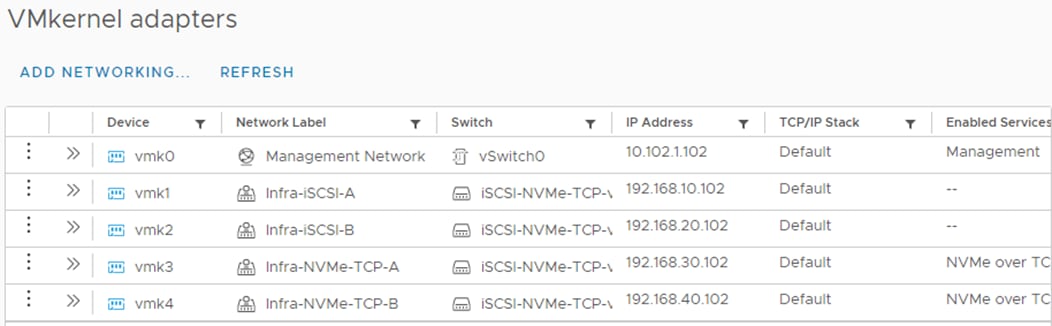
Step 57. Repeat all steps in this procedure for all other iSCSI-booted ESXi hosts.
Procedure 3. Set Up VMkernel Ports and Virtual Switch
Step 1. In the vCenter HTML5 Interface, under Hosts and Clusters select the ESXi host.
Step 2. In the center pane, click the Configure tab.
Step 3. In the list, click Virtual switches under Networking.
Step 4. Expand Standard Switch: vSwitch0.
Step 5. Select MANAGE PHYSICAL ADAPTERS. Click the plus sign to add an adapter.
Step 6. Select vmnic1 and click OK.
Step 7. Ensure vmnic1 is now listed as an Active adapter and click OK.
Step 8. Select EDIT to Edit settings on vSwitch0.
Step 9. Change the MTU to 9000 and click OK.
Step 10. In the center pane, to the right of VM Network click “…” > Remove to remove the port group. Click YES on the confirmation.
Step 11. Click ADD NETWORKING to add a new VM port group.
Step 12. Select Virtual Machine Port Group for a Standard Switch and click NEXT.
Step 13. Ensure vSwitch0 is shown for Select an existing standard switch and click NEXT.
Step 14. Name the port group “IB-MGMT Network” and leave the VLAN ID set to None (0). Click NEXT.
Step 15. Click FINISH to complete adding the IB-MGMT Network VM port group.
Step 16. Click ADD NETWORKING to add a new VM port group.
Step 17. Select Virtual Machine Port Group for a Standard Switch and click NEXT.
Step 18. Ensure vSwitch0 is shown for Select an existing standard switch and click NEXT.
Step 19. Name the port group “OOB-MGMT Network” and set the VLAN ID to <oob-mgmt-vlan-id> (for example, 1020). Click NEXT.
Step 20. Click FINISH to complete adding the IB-MGMT Network VM port group.
Step 21. Under Networking, click VMkernel adapters.
Step 22. In the center pane, click ADD NETWORKING.
Step 23. Make sure VMkernel Network Adapter is selected and click NEXT.
Step 24. Select an existing standard switch and click BROWSE. Select vSwitch0 and click OK. Click NEXT.
Step 25. For Network label, enter VMkernel-Infra-NFS.
Step 26. Enter <infra-nfs-vlan-id> (for example, 3050) for the VLAN ID.
Step 27. Select Custom for MTU and set the value to 9000.
Step 28. Leave the Default TCP/IP stack selected and do not choose any of the Enabled services. Click NEXT.
Step 29. Select Use static IPv4 settings and enter the IPv4 address and subnet mask for the Infra-NFS VMkernel port for this ESXi host.
Step 30. Click NEXT.
Step 31. Review the settings and click FINISH to create the VMkernel port.
Step 32. To verify the vSwitch0 setting, under Networking, click Virtual switches, then expand vSwitch0. The properties for vSwitch0 should be similar to:
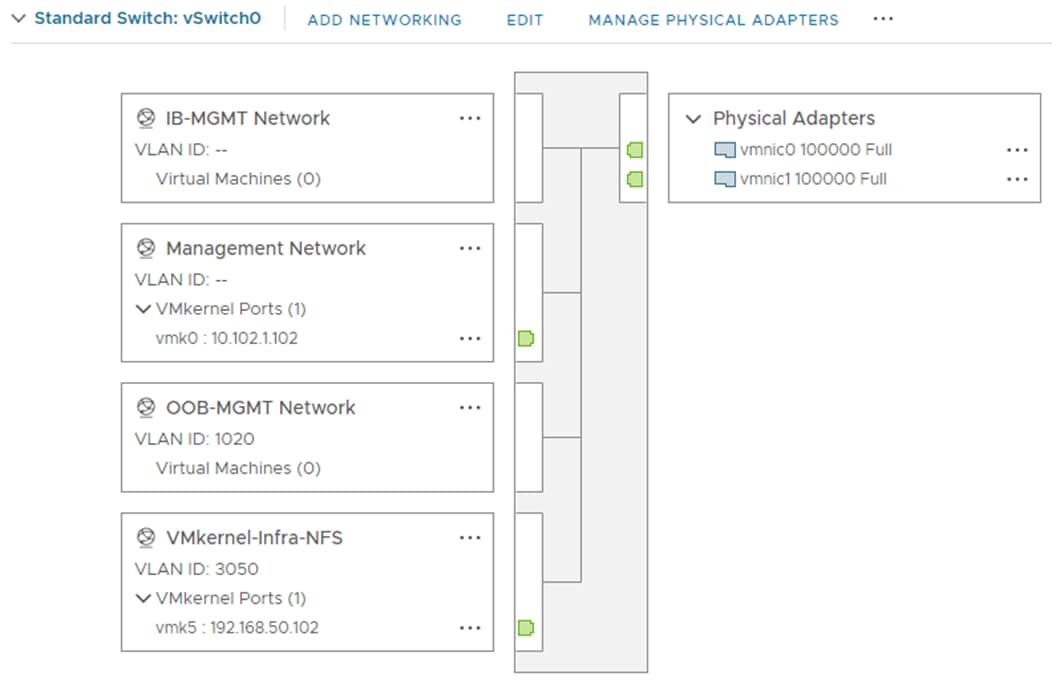
Step 33. Repeat steps 1 – 32 for all the ESXi hosts being added.
Procedure 4. Mount Required Datastores
Step 1. From the vCenter Home screen, click Storage (or Datastores).
Step 2. Expand the vCenter then expand FlexPod-DC.
Step 3. Right-click infra_datastore and select Mount Datastore to Additional Hosts.
Step 4. Select all the ESXi host(s) and click OK.
Step 5. Repeat steps 1 – 4 to mount the infra_swap and vCLS datastores on all the ESXi host(s).
Step 6. Select infra_datastore and in the center pane, click Hosts. Verify that all the ESXi host(s) are listed. Repeat this process to verify that both infra_swap and vCLS datastores are also mounted on all hosts.
Procedure 5. Configure ESXi Host Swap
Step 1. In the vCenter HTML5 Interface, under Hosts and Clusters select the ESXi host.
Step 2. In the center pane, click the Configure tab.
Step 3. In the list under Virtual Machines, select Swap File Location.
Step 4. In the window on the right, click EDIT.
Step 5. Select the infra_swap datastore and click OK.
Step 6. Repeat this procedure for all the ESXi hosts.
Procedure 6. Configure NTP on ESXi Host
Step 1. In the vCenter HTML5 Interface, under Hosts and Clusters select the ESXi host.
Step 2. In the center pane, select the Configure tab.
Step 3. In the list under System, click Time Configuration.
Step 4. Click ADD SERVICE > Network Time Protocol.
Step 5. Enter the NTP Server IP addresses (the Nexus switch IB-MGMT distribution IPs) in the NTP servers box separated by a comma and click OK.
Step 6. Verify that NTP service is now running, and the clock is now set to correct time.
Step 7. Repeat these steps for all the ESXi hosts.
Procedure 7. Change ESXi Power Management Policy
Note: Implementation of this policy is recommended in Performance Tuning Guide for Cisco UCS M6 Servers: https://www.cisco.com/c/en/us/products/collateral/servers-unified-computing/ucs-b-series-blade-servers/performance-tuning-guide-ucs-m6-servers.html for maximum VMware ESXi performance. This policy can be adjusted based on your requirements.
Step 1. In the vCenter HTML5 Interface, under Hosts and Clusters select the ESXi host.
Step 2. In the center pane, select the Configure tab.
Step 3. Under Hardware, click Overview. Scroll to the bottom and next to Power Management, click EDIT POWER POLICY.
Step 4. Select High performance and click OK.
Procedure 8. Add the ESXi Host(s) to the VMware Virtual Distributed Switch
Step 1. From the VMware vSphere HTML5 Client, click Networking.
Step 2. Right-click vDS0 and select Add and Manage Hosts.
Step 3. Ensure that Add hosts is selected and click NEXT.
Step 4. Select all ESXi host(s) listed and click OK. Click NEXT.
Step 5. If all hosts had alignment in the ESXi console screen between vmnic numbers and vNIC numbers, leave Adapters on all hosts selected. To the right of vmnic2, use the pulldown to select Uplink 1. To the right of vmnic3, use the pulldown to select Uplink 2. Click NEXT. If the vmnic numbers and vNIC numbers did not align, select Adapters per host and select vDS uplinks individually on each host.
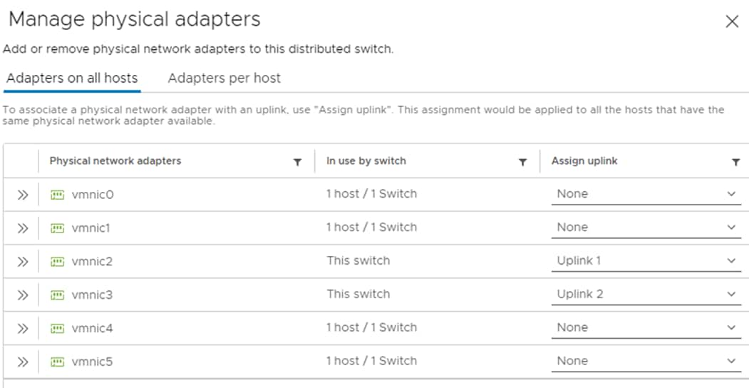
Note: It is important to assign the uplinks as defined in these steps. This allows the port groups to be pinned to the appropriate Cisco UCS Fabric.
Step 6. Click NEXT.
Step 7. Do not migrate any VMkernel ports and click NEXT.
Step 8. Do not migrate any VM ports and click NEXT.
Step 9. Click FINISH to complete adding the ESXi host(s) to the vDS.
Procedure 9. Add the vMotion VMkernel Port to the ESXi Host
Step 1. In the vCenter HTML5 Interface, under Hosts and Clusters select the ESXi host.
Step 2. Click the Configure tab.
Step 3. In the list under Networking, click VMkernel adapters.
Step 4. Select Add Networking to add host networking.
Step 5. Make sure VMkernel Network Adapter is selected and click NEXT.
Step 6. Select BROWSE to the right of Select an existing network.
Step 7. Select vMotion on vDS0 and click OK.
Step 8. Click NEXT.
Step 9. Make sure the Network label is vMotion with the vDS in parenthesis. From the drop-down list, select Custom for MTU and make sure the MTU is set to 9000. Select the vMotion TCP/IP stack and click NEXT.
Step 10. Select Use static IPv4 settings and input the host’s vMotion IPv4 address and Subnet mask.
Step 11. Click NEXT.
Step 12. Review the parameters and click FINISH to add the vMotion VMkernel port. The VMkernel adapter listing should be similar to the following (FC-booted hosts will not have the iSCSI and NVMe-TCP VMkernel adapters):
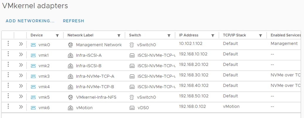
Step 13. Repeat these steps to add a vMotion VMkernel Adapter to each ESXi host.
Note: (Optional) If NetApp ONTAP Tools is installed, under Hosts and Clusters, right-click the host and click NetApp ONTAP Tools > Set Recommended Values. Reboot the host. If this is a brand-new installation, this step will be executed when NetApp ONTAP Tools is setup later in this document
Finalize the vCenter and ESXi Setup
This procedure enables you to finalize the VMware installation.
Procedure 1. Verify ESXi Host Multi-Path configuration
Note: For FC SAN-booted ESXi hosts, verify that the boot disk contains all required FC paths.
Step 1. In the vCenter HTML5 Interface, under Hosts and Clusters select the ESXi host.
Step 2. In the center pane, click the Configure tab.
Step 3. In the list under Storage, click Storage Devices. Make sure the NetApp Fibre Channel or iSCSI Disk is selected.
Step 4. Select the Paths tab.
Step 5. Ensure that 4 paths appear, two of which should have the status Active (I/O).
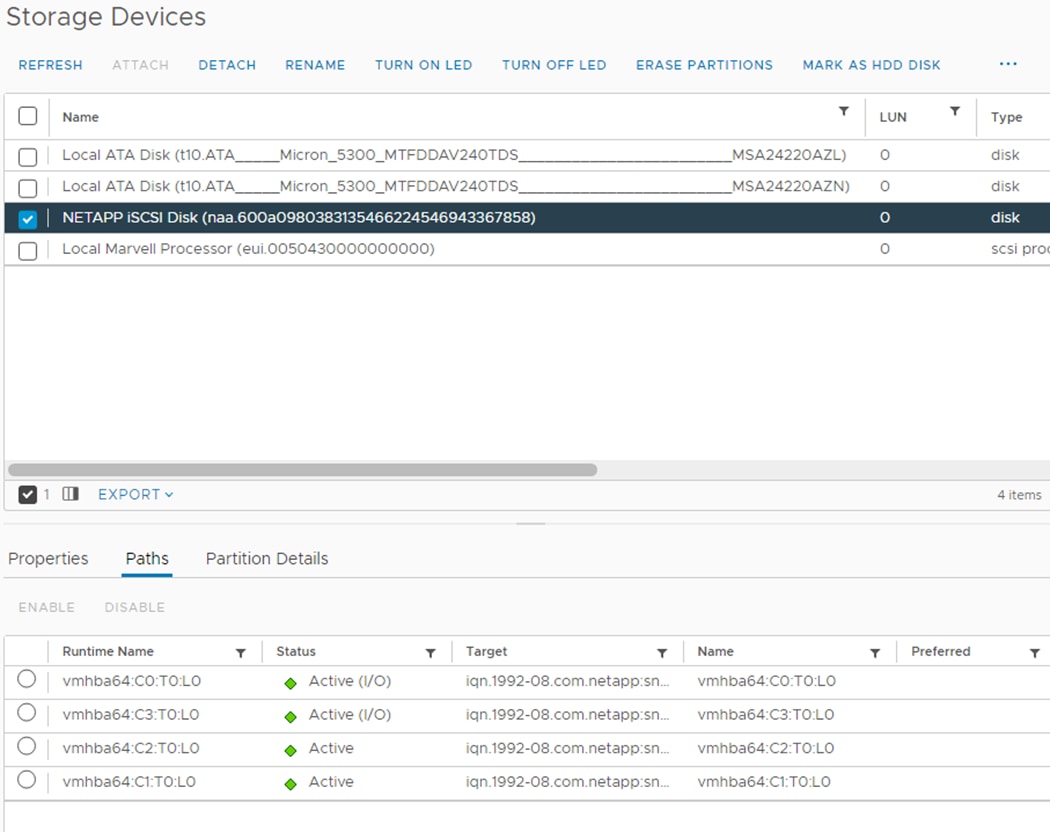
Procedure 2. VMware ESXi 7.0 U3 TPM Attestation
Note: If your Cisco UCS servers have Trusted Platform Module (TPM) 2.0 modules installed, the TPM can provide assurance that ESXi has booted with UEFI Secure Boot enabled and using only digitally signed code. In the Cisco UCS Configuration section of this document, UEFI secure boot was enabled in the boot order policy. A server can boot with UEFI Secure Boot with or without a TPM 2.0 module. If it has a TPM, VMware vCenter can attest that the server booted with UEFI Secure Boot. To verify the VMware ESXi 7.0 U3 TPM Attestation, follow these steps:
Step 1. For Cisco UCS servers that have TPM 2.0 modules installed, TPM Attestation can be verified in the vSphere HTML5 Client.
Step 2. In the vCenter HTML5 Interface, under Hosts and Clusters select the cluster.
Step 3. In the center pane, click the Monitor tab.
Step 4. Click Monitor > Security. The Attestation status will show the status of the TPM:
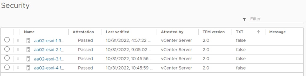
Note: It may be necessary to disconnect and reconnect or reboot a host from vCenter to get it to pass attestation the first time.
Procedure 3. Avoiding Boot Failure When UEFI Secure Booted Server Profiles are Moved
Typically, hosts in FlexPod Datacenter are configured for boot from SAN. Cisco UCS supports stateless compute where a server profile can be moved from one blade or compute node to another seamlessly.
When a server profile is moved from one blade to another blade server with the following conditions, the ESXi host runs into PSOD and ESXi will fail to boot:
● TPM present in the node (Cisco UCS M5 and M6 family servers)
● Host installed with ESXi 7.0 U2 or above
● Boot mode is UEFI Secure
● Error message: Unable to restore system configuration. A security violation was detected. https://via.vmw.com/security-violation.
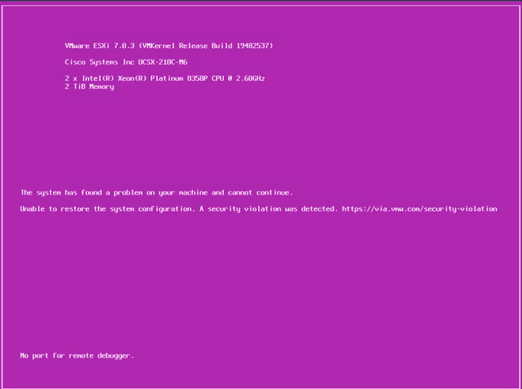
Step 1. Log into the host using SSH.
Step 2. Gather the recovery key using this command:
[root@aa02-esxi-1:~] esxcli system settings encryption recovery list
Recovery ID Key
-------------------------------------- ---
{74AC4D68-FE47-491F-B529-6355D4AAF52C} 529012-402326-326163-088960-184364-097014-312164-590080-407316-660658-634787-601062-601426-263837-330828-197047
Step 3. Store the keys from all hosts in a safe location.
Step 4. After associating the Server Profile to the new compute-node or blade, stop the ESXi boot sequence by pressing Shift + O when you see the ESXi boot screen.
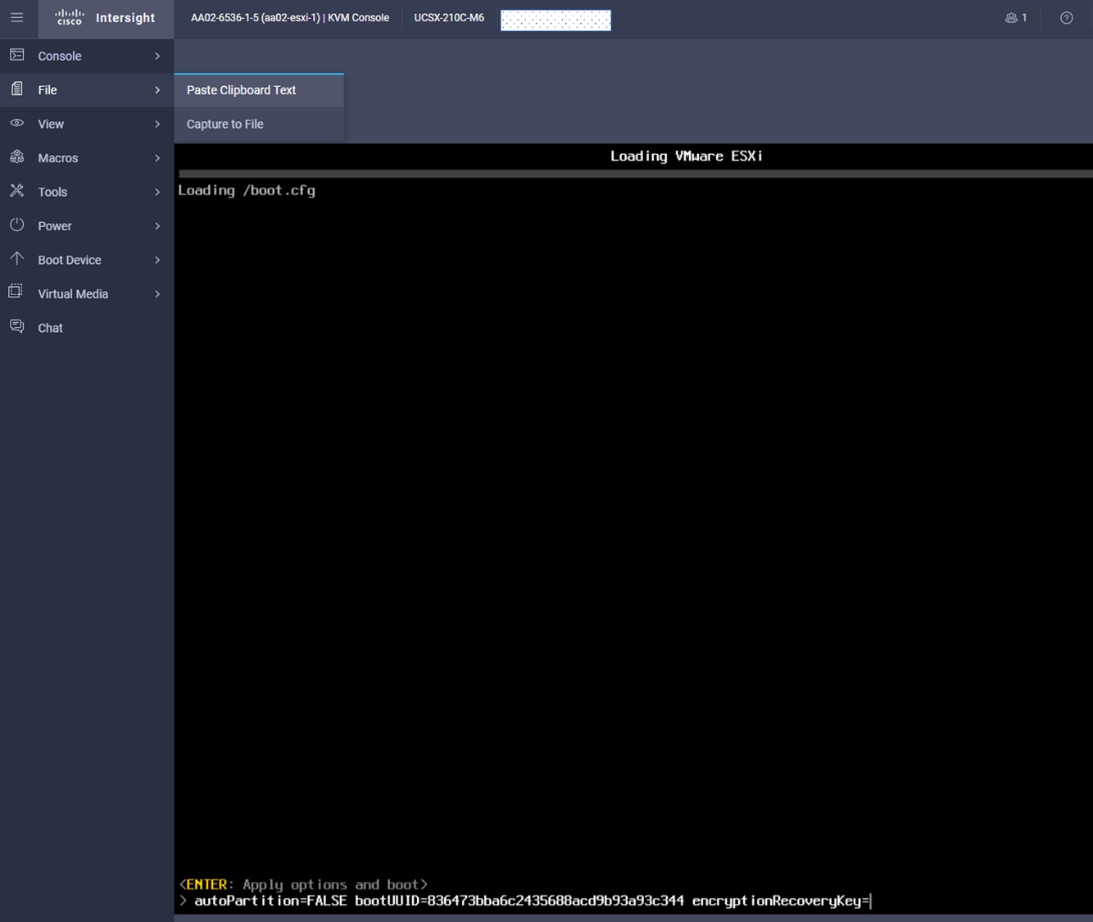
Step 5. Add the recovery key using following boot option: encryptionRecoveryKey=recovery_key. Press Enter to continue the boot process.
Step 6. To persist the change, enter the following command at the VMware ESXi ssh command prompt:
/sbin/auto-backup.sh
Note: For more information, refer to: https://docs.vmware.com/en/VMware-vSphere/7.0/com.vmware.vsphere.security.doc/GUID-23FFB8BB-BD8B-46F1-BB59-D716418E889A.html.
Storage Configuration – NetApp ONTAP NVMe Configuration and Finalizing NetApp ONTAP Storage
This chapter contains the following:
● Manual NetApp ONTAP Storage Configuration Part 3
Manual NetApp ONTAP Storage Configuration Part 3
This section contains the following:
● NetApp ONTAP NVMe Configuration
● VMware vSphere NVMe Configuration
● Finalize the NetApp ONTAP Storage Configuration
NetApp ONTAP NVMe Configuration
Note: This configuration is required for NVMe/FC and NVMe/TCP setup.
Procedure 1. Configure NetApp ONTAP NVMe
Step 1. Create NVMe namespace.
vserver nvme namespace create -vserver <SVM_name> -path <namespace_path> -size <size_of_namespace> -ostype <OS_type>
aa02-a800::> vserver nvme namespace create -versver Infra-SVM -path /vol/nvme_datastore/nvme_datastore -size 500G -ostype vmware
Step 2. Create NVMe subsystem.
vserver nvme subsystem create -vserver <SVM_name> -subsystem <name_of_subsystem> -ostype <OS_type>
aa02-a800::> vserver nvme subsystem create -vserver Infra-SVM -subsystem fp-esxi-hosts -ostype vmware
Step 3. Verify the subsystem was created.
aa02-a800::> vserver nvme subsystem show -vserver Infra-SVM
Vserver Subsystem Target NQN
------- ------------ --------------------------------------------------------
Infra-SVM
fp-esxi-hosts
nqn.1992-08.com.netapp:sn.90e9cb71515311ed978d00a098e217cb:subsystem.fp-esxi-hosts
VMware vSphere NVMe Configuration
Procedure 1. Configure FC-NVMe and NVMe-TCP on ESXi Host
Note: Steps 1 and 2 have already been completed in the VMware ESXi Manual Configuration section of this document. Just run Step 2 and if HppManageDegradedPaths is 0, avoid the reboot and go to Step 3.
Step 1. Enable FC-NVMe and NVMe-TCP with Asymmetric Namespace Access (ANA).
[root@aa02-esxi-1:~] esxcfg-advcfg -s 0 /Misc/HppManageDegradedPaths
Step 2. Reboot the Host. After reboot, verify that the HppManageDegradedPaths parameter is now disabled.
[root@aa02-esxi-1:~] esxcfg-advcfg -g /Misc/HppManageDegradedPaths
Value of HppManageDegradedPaths is 0
Step 3. Get the ESXi host NQN string and add this to corresponding subsystem on the NetApp ONTAP array.
[root@aa02-esxi-1:~] esxcli nvme info get
Host NQN: nqn.2014-08.com.cisco.flexpodb4:nvme:aa02-esxi-1
Step 4. Add the host NQN(s) obtained in the last step to the NetApp ONTAP subsystem one by one.
aa02-a800::> vserver nvme subsystem host add -vserver Infra-SVM -subsystem fp-esxi-hosts -host-nqn nqn.2014-08.com.cisco.flexpodb4:nvme:aa02-esxi-1
aa02-a800::> vserver nvme subsystem host add -vserver Infra-SVM -subsystem fp-esxi-hosts -host-nqn nqn.2014-08.com.cisco.flexpodb4:nvme:aa02-esxi-2
aa02-a800::> vserver nvme subsystem host add -vserver Infra-SVM -subsystem fp-esxi-hosts -host-nqn nqn.2014-08.com.cisco.flexpodb4:nvme:aa02-esxi-3
aa02-a800::> vserver nvme subsystem host add -vserver Infra-SVM -subsystem fp-esxi-hosts -host-nqn nqn.2014-08.com.cisco.flexpodb4:nvme:aa02-esxi-4
Note: It is important to add the host NQNs using separate commands as shown above. NetApp ONTAP will accept a comma separated list of host NQNs without generating an error message however the ESXi hosts will not be able to map the namespace.
Step 5. Verify the host NQNs were added successfully.
aa02-a800::> vserver nvme subsystem host show -vserver Infra-SVM
Vserver Subsystem Host NQN
------- --------- ----------------------------------------------------------
Infra-SVM
fp-esxi-hosts
nqn.2014-08.com.cisco.flexpodb4:nvme:aa02-esxi-1
nqn.2014-08.com.cisco.flexpodb4:nvme:aa02-esxi-2
nqn.2014-08.com.cisco.flexpodb4:nvme:aa02-esxi-3
nqn.2014-08.com.cisco.flexpodb4:nvme:aa02-esxi-4
4 entries were displayed.
Note: In the example above, host NQNs for two FC (aa02-esxi-1 and aa02-esxi-3) and two iSCSI (aa02-esxi-2 and aa02-esxi-4) ESXi hosts in an ESXi cluster were added to the same subsystem to create a shared datastore.
Step 6. Map the Namespace to the subsystem.
aa02-a800::> vserver nvme subsystem map add -vserver Infra-SVM -subsystem fp-esxi-hosts -path /vol/nvme_datastore/nvme_datastore
Step 7. Verify the Namespace is mapped to the subsystem.
aa02-a800::> vserver nvme subsystem map show -vserver Infra-SVM -instance
Vserver Name: Infra-SVM
Subsystem: fp-esxi-hosts
NSID: 00000001h
Namespace Path: /vol/nvme_datastore/nvme_datastore
Namespace UUID: 6aa73cc4-1c77-4b5b-a488-769f96580a8a
Step 8. Reboot each ESXi host and then verify that the NetApp ONTAP target FC-NVMe controllers are properly discovered on the ESXi Host:
Note: For NVMe-TCP datastore mappings, software adapters and controllers will be added in the next procedure.
[root@aa02-esxi-3:~] esxcli nvme controller list
Name Controller Number Adapter Transport Type Is Online
---------------------------------------------------------------------------------------------------------------------------- ----------------- ------- -------------- ---------
nqn.1992-08.com.netapp:sn.90e9cb71515311ed978d00a098e217cb:subsystem.fp-esxi-hosts#vmhba64#200500a098e217ca:200800a098e217ca 264 vmhba64 FC true
nqn.1992-08.com.netapp:sn.90e9cb71515311ed978d00a098e217cb:subsystem.fp-esxi-hosts#vmhba64#200500a098e217ca:200600a098e217ca 262 vmhba64 FC true
nqn.1992-08.com.netapp:sn.90e9cb71515311ed978d00a098e217cb:subsystem.fp-esxi-hosts#vmhba65#200500a098e217ca:200700a098e217ca 270 vmhba65 FC true
nqn.1992-08.com.netapp:sn.90e9cb71515311ed978d00a098e217cb:subsystem.fp-esxi-hosts#vmhba65#200500a098e217ca:200900a098e217ca 272 vmhba65 FC true
[root@aa02-esxi-4:~] esxcli nvme controller list
Name
Controller Number Adapter Transport Type Is Online
------------------------------------------------------------------------------------------------------------- ----------------- ------- -------------- ---------
nqn.1992-08.com.netapp:sn.90e9cb71515311ed978d00a098e217cb:subsystem.fp-esxi-hosts#vmhba65#192.168.30.32:4420 257 vmhba65 TCP true
nqn.1992-08.com.netapp:sn.90e9cb71515311ed978d00a098e217cb:subsystem.fp-esxi-hosts#vmhba65#192.168.30.31:4420 258 vmhba65 TCP true
nqn.1992-08.com.netapp:sn.90e9cb71515311ed978d00a098e217cb:subsystem.fp-esxi-hosts#vmhba66#192.168.40.32:4420 260 vmhba66 TCP true
nqn.1992-08.com.netapp:sn.90e9cb71515311ed978d00a098e217cb:subsystem.fp-esxi-hosts#vmhba66#192.168.40.31:4420 261 vmhba66 TCP true
Procedure 2. Configure ESXi Host NVMe over FC and NVMe over TCP Datastore
Step 1. To verify that the NVMe Fibre Channel Disk is mounted on each ESXi host, log into the VMware vCenter using a web-browser.
Step 2. Under Hosts and Clusters select an ESXi host running FC-NVMe. In the center pane, go to Configure > Storage > Storage Devices. The NVMe Fibre Channel Disk should be listed under Storage Devices.
Step 3. Select the NVMe Fibre Channel Disk, then select Paths underneath. Verify 2 paths have a status of Active (I/O) and 2 paths have a status of Active.
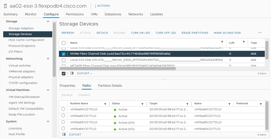
Step 4. Repeat Step 3 for all the FC-NVMe hosts.
Step 5. Under Hosts and Clusters select an ESXi host running NVMe-TCP. In the center pane, go to Configure > Storage > Storage Adapters.
Step 6. Click ADD SOFTWARE-ADAPTER > Add NVMe over TCP adapter. Use the pulldown to select vmnic4/nenic and click OK. A new vmhba should appear under Storage Adapters.
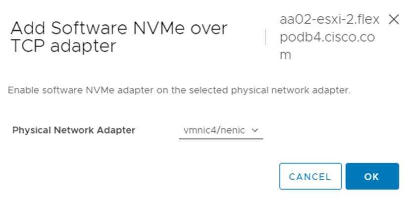
Step 7. Click ADD SOFTWARE-ADAPTER > Add NVMe over TCP adapter to add a second vmhba. Use the pulldown to select vmnic5/nenic and click OK. A new vmhba should appear under Storage Adapters.
Step 8. Select the first VMware NVMe over TCP Storage Adapter added (for example, vmhba65). In the middle of the window, select the Controllers tab. Click ADD CONTROLLER.
Step 9. Enter the IP address of nvme-tcp-lif-01a and click DISCOVER CONTROLLERS. Select the two controllers in the Infra-NVMe-TCP-A subnet and click OK. The two controllers should now appear under the Controllers tab.
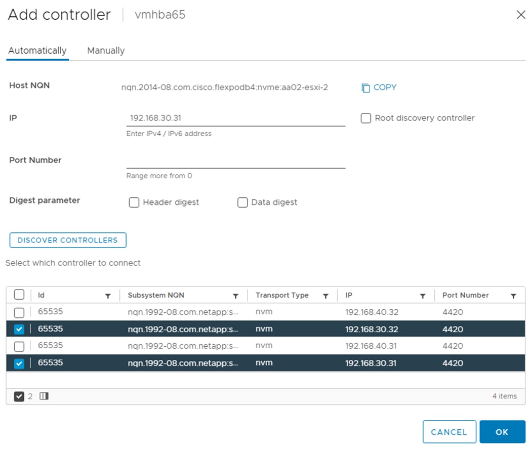
Step 10. Select the second VMware NVMe over TCP Storage Adapter added (for example, vmhba66). In the middle of the window, select the Controllers tab. Click ADD CONTROLLER.
Step 11. Enter the IP address of nvme-tcp-lif-02b and click DISCOVER CONTROLLERS. Select the two controllers in the Infra-NVMe-TCP-B subnet and click OK. The two controllers should now appear under the Controllers tab.
Step 12. Repeat steps 5-11 for all ESXi hosts running NVMe-TCP.
Step 13. For any one of these hosts, right-click the host under Hosts and Clusters and select Storage > New Datastore. Leave VMFS selected and click NEXT.
Step 14. Name the datastore (for example, nvme_datastore) and select the NVMe Disk. Click NEXT.
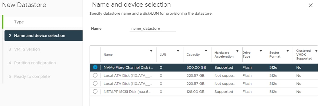
Step 15. Leave VMFS 6 selected and click NEXT.
Step 16. Leave all Partition configuration values at the default values and click NEXT.
Step 17. Review the information and click FINISH.
Step 18. Select Storage and select the new NVMe datastore. In the center pane, select Hosts. Ensure all the NVMe hosts have mounted the datastore.
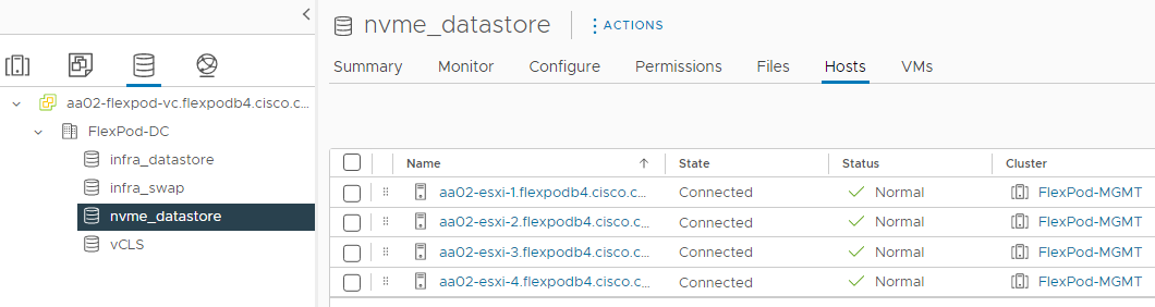
Note: If any hosts are missing from the list, it may be necessary to put the host in Maintenance Mode and reboot the host. If you happen to have hosts with both FC-boot and iSCSI-boot and are running both FC-NVMe and NVMe-TCP, notice that the same datastore is mounted on both types of hosts and that the only difference in the storage configuration is what LIF the traffic is coming in on.
Finalize the NetApp ONTAP Storage Configuration
Make the following configuration changes to finalize the NetApp controller configuration.
Procedure 1. Configure DNS for infrastructure SVM
Step 1. To configure DNS for the Infra-SVM, run the following command:
dns create -vserver <vserver-name> -domains <dns-domain> -nameserve <dns-servers>
Example:
dns create -vserver Infra-SVM -domains flexpodb4.cisco.com -nameservers 10.102.1.151,10.102.1.152
Procedure 2. Create and enable auditing configuration for the SVM
Step 1. To create auditing configuration for the SVM, run the following command:
vserver audit create -vserver Infra-SVM -destination /audit_log
Step 2. Run the following command to enable audit logging for the SVM:
vserver audit enable -vserver Infra-SVM
Note: It is recommended that you enable audit logging so you can capture and manage important support and availability information. Before you can enable auditing on the SVM, the SVM’s auditing configuration must already exist.
Note: If the users do not perform the above configuration steps for the SVM, they will observe a warning in AIQUM stating “Audit Log is disabled.”
Procedure 3. Delete the residual default broadcast domains with ifgroups (Applicable for 2-node cluster only)
Step 1. To delete the residual default broadcast domains that are not in use, run the following commands:
broadcast-domain delete -broadcast-domain <broadcast-domain-name>
broadcast-domain delete -broadcast-domain Default-1
broadcast-domain delete -broadcast-domain Default-2
Procedure 4. Test Auto Support
Step 1. To test the Auto Support configuration by sending a message from all nodes of the cluster, run the following command:
autosupport invoke -node * -type all -message “FlexPod ONTAP storage configuration completed”
FlexPod Management Tools Setup
This chapter contains the following:
● Cisco Intersight Hardware Compatibility List (HCL) Status
● NetApp ONTAP Tools 9.11 Deployment
● Provision Datastores using NetApp ONTAP Tools (Optional)
● Virtual Volumes – vVol (Optional)
● NetApp SnapCenter 4.7 Configuration
● Active IQ Unified Manager 9.11P1 Installation
● Configure Active IQ Unified Manager
● Deploy Cisco Intersight Assist Appliance
● Claim VMware vCenter using Cisco Intersight Assist Appliance
● Claim NetApp Active IQ Manager using Cisco Intersight Assist Appliance
● Claim Cisco Nexus Switches using Cisco Intersight Assist Appliance
● Claim Cisco MDS Switches using Cisco Intersight Assist Appliance
● Create a FlexPod XCS Integrated System
● Cisco Data Center Network Manager (DCNM)–SAN
Cisco Intersight Hardware Compatibility List (HCL) Status
Cisco Intersight evaluates the compatibility of customer’s UCS system to check if the hardware and software have been tested and validated by Cisco or Cisco partners. Intersight reports validation issues after checking the compatibility of the server model, processor, firmware, adapters, operating system, and drivers, and displays the compliance status with the Hardware Compatibility List (HCL).
To determine HCL compatibility for VMware ESXi, Cisco Intersight uses Cisco UCS Tools. The Cisco UCS Tools is part of VMware ESXi Cisco custom ISO, and no additional configuration is required.
For more details on Cisco UCS Tools manual deployment and troubleshooting, refer to: https://intersight.com/help/saas/resources/cisco_ucs_tools#about_cisco_ucs_tools
Procedure 1. View Compute Node Hardware Compatibility
Step 1. To find detailed information about the hardware compatibility of a compute node, in Cisco Intersight select Infrastructure Service > Operate > Servers in the left menu bar, click a server, select HCL.
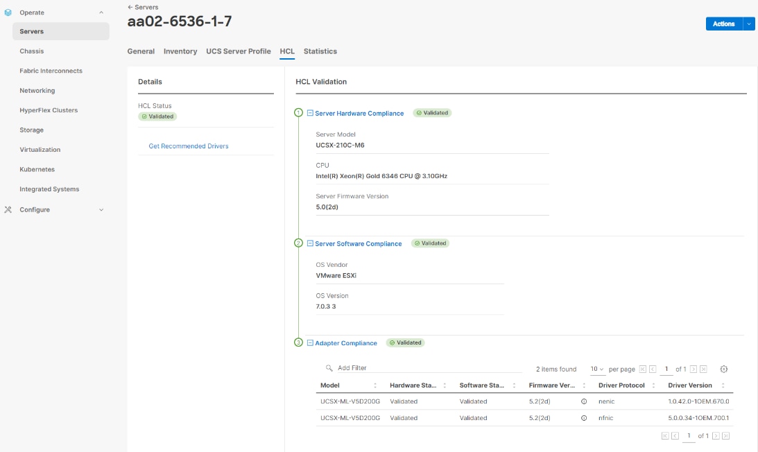
NetApp ONTAP Tools 9.11 Deployment
The NetApp ONTAP tools for VMware vSphere provide end-to-end life cycle management for virtual machines in VMware environments that use NetApp storage systems. It simplifies storage and data management for VMware environments by enabling administrators to directly manage storage within the vCenter Server. This topic describes the deployment procedures for the NetApp ONTAP Tools for VMware vSphere.
NetApp ONTAP Tools for VMware vSphere 9.11 Pre-installation Considerations
The following licenses are required for NetApp ONTAP Tools on storage systems that run NetApp ONTAP 9.8 or above:
● Protocol licenses (NFS, FCP, and/or iSCSI)
● NetApp FlexClone ((optional) Required for performing test failover operations for SRA and for vVols operations of VASA Provider.
● NetApp SnapRestore (for backup and recovery).
● The NetApp SnapManager Suite.
● NetApp SnapMirror or NetApp SnapVault (Optional - required for performing failover operations for SRA and VASA Provider when using vVols replication).
The Backup and Recovery capability has been integrated with SnapCenter and requires additional licenses for SnapCenter to perform backup and recovery of virtual machines and applications.
Note: Beginning with NetApp ONTAP 9.10.1, all licenses are delivered as NLFs (NetApp License File). NLF licenses can enable one or more NetApp ONTAP features, depending on your purchase. NetApp ONTAP 9.10.1 also supports 28-character license keys using System Manager or the CLI. However, if an NLF license is installed for a feature, you cannot install a 28-character license key over the NLF license for the same feature.
Table 15. Port Requirements for NetApp ONTAP Tools
| TCP Port |
Requirement |
| 443 (HTTPS) |
Secure communications between VMware vCenter Server and the storage systems |
| 8143 (HTTPS) |
NetApp ONTAP Tools listens for secure communications |
| 9083 (HTTPS) |
VASA Provider uses this port to communicate with the vCenter Server and obtain TCP/IP settings |
| 7 |
NetApp ONTAP tools sends an echo request to NetApp ONTAP to verify reachability and is required only when adding storage system and can be disabled later. |
Note: The requirements for deploying NetApp ONTAP Tools are listed here.
Procedure 1. Install NetApp ONTAP Tools Manually
Step 1. Download the NetApp ONTAP Tools 9.11 OVA (NETAPP-ONTAP-TOOLS-FOR-VMWARE-VSPHERE-9.11-8450.OVA) from NetApp support: https://mysupport.netapp.com/site/products/all/details/otv/downloads-tab/download/63792/9.11
Step 2. Launch the vSphere Web Client and navigate to Hosts and Clusters.
Step 3. Select ACTIONS for the FlexPod-DC datacenter and select Deploy OVF Template.
Step 4. Browse to the NetApp ONTAP tools OVA file and select the file.
Step 5. Enter the VM name and select a datacenter or folder to deploy the VM and click NEXT.
Step 6. Select a host cluster resource to deploy OVA and click NEXT.
Step 7. Review the details and accept the license agreement.
Step 8. Select the infra_datastore volume and Select the Thin Provision option for the virtual disk format.
Step 9. From Select Networks, select a destination network (for example, IB-MGMT) and click NEXT.
Step 10. From Customize Template, enter the NetApp ONTAP tools administrator password, vCenter name or IP address and other configuration details and click NEXT.
Step 11. Review the configuration details entered and click FINISH to complete the deployment of NetApp ONTAP-Tools VM.
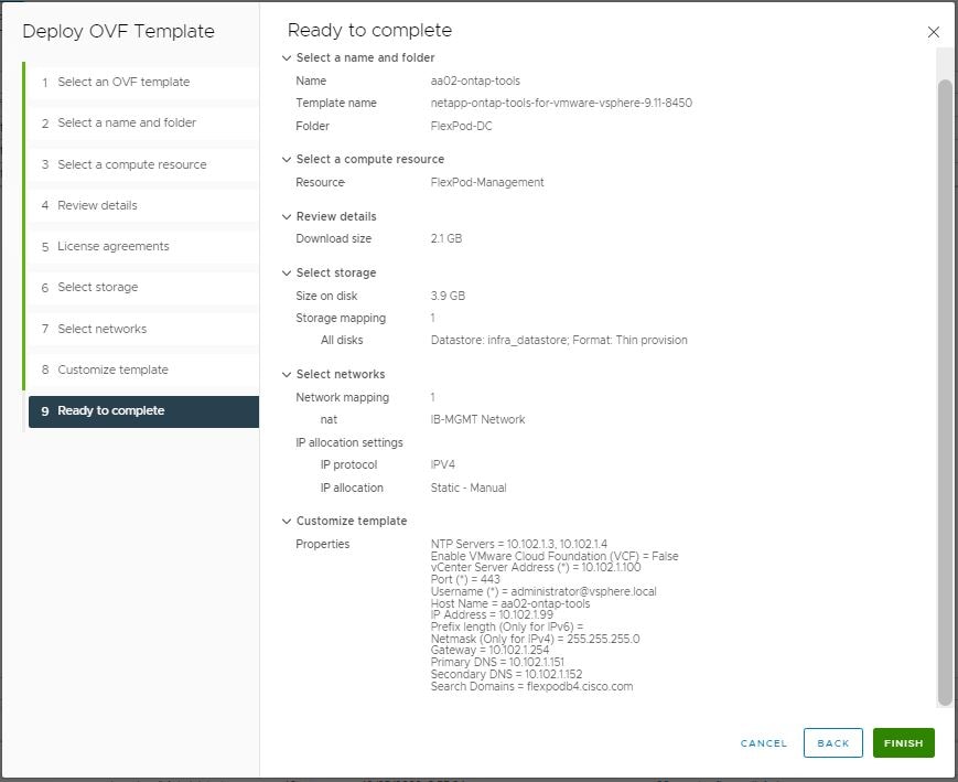
Step 12. Power on the NetApp ONTAP-tools VM and open the VM console.
Step 13. During the NetApp ONTAP-tools VM boot process, you see a prompt to install VMware Tools. From vCenter, right-click the ONTAP-tools VM > Guest OS > Install VMware Tools.
Step 14. Networking configuration and vCenter registration information was provided during the OVF template customization, therefore after the VM is up and running, NetApp ONTAP-Tools and vSphere API for Storage Awareness (VASA) is registered with vCenter.
Step 15. Refresh the vCenter Home Screen and confirm that the NetApp ONTAP tools is installed.
Note: The NetApp ONTAP tools vCenter plug-in is only available in the vSphere HTML5 Client and is not available in the vSphere Web Client.
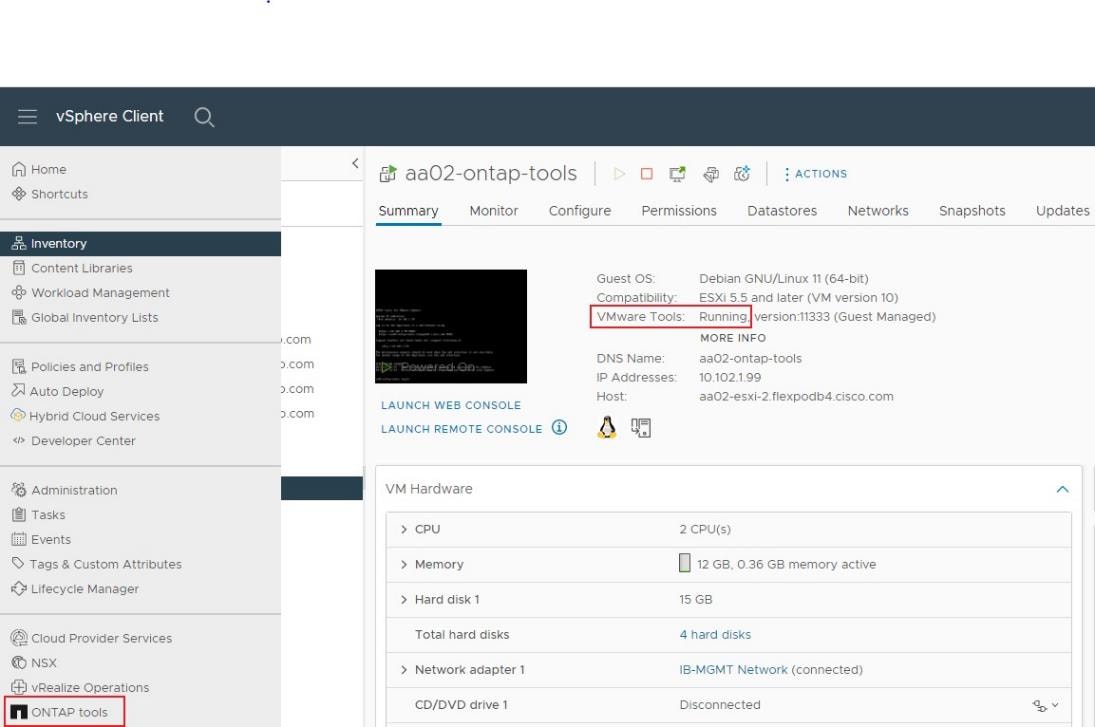
Procedure 2. Download the NetApp NFS Plug-in for VAAI
Note: The NFS Plug-in for VAAI was previously installed on the ESXi hosts along with the Cisco UCS VIC drivers; it is not necessary to re-install the plug-in at this time. However, for any future additional ESXi host setup, instead of using esxcli commands, NetApp ONTAP-Tools can be utilized to install the NetApp NFS plug-in. The steps below upload the latest version of the plugin to NetApp ONTAP tools.
Step 1. Download the NetApp NFS Plug-in 2.0 for VMware file from: https://mysupport.netapp.com/site/products/all/details/nfsplugin-vmware-vaai/downloads-tab.
Step 2. Unzip the file and extract NetApp_bootbank_NetAppNasPlugin_2.0-15.vib from vib20 > NetAppNasPlugin.
Step 3. Rename the .vib file to NetAppNasPlugin.vib to match the predefined name that NetApp ONTAP tools uses.
Step 4. Click Settings in the NetApp ONTAP tool Getting Started page.
Step 5. Click NFS VAAI Tools tab.
Step 6. Click Change in the Existing version section.
Step 7. Browse and select the renamed .vib file, and then click Upload to upload the file to the virtual appliance.
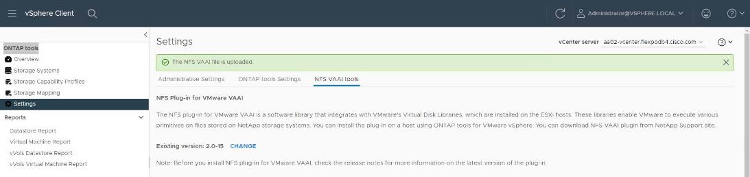
Note: The next step is only required on the hosts where NetApp VAAI plug-in was not installed alongside Cisco VIC driver installation.
Step 8. In the Install on ESXi Hosts section, select the ESXi host where the NFS Plug-in for VAAI is to be installed, and then click Install.
Step 9. Reboot the ESXi host after the installation finishes.
Procedure 3. Verify the VASA Provider
Note: The VASA provider for NetApp ONTAP is enabled by default during the installation of the NetApp ONTAP tools.
Step 1. From the vSphere Client, click Menu > ONTAP tools.
Step 2. Click Settings.
Step 3. Click Manage Capabilities in the Administrative Settings tab.
Step 4. In the Manage Capabilities dialog box, click Enable VASA Provider if it was not pre-enabled.
Step 5. Enter the IP address of the virtual appliance for NetApp ONTAP tools, VASA Provider, and VMware Storage Replication Adapter (SRA) and the administrator password, and then click Apply.
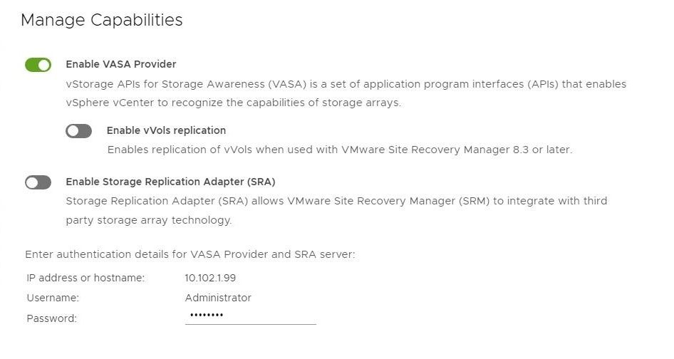
Procedure 4. Discover and Add Storage Resources
Step 1. Using the vSphere Web Client, log in to the vCenter. If the vSphere Web Client was previously opened, close the tab, and then reopen it.
Step 2. In the Home screen, click the Home tab and click ONTAP tools.
Note: When using the cluster admin account, add storage from the cluster level.
Note: You can modify the storage credentials with the vsadmin account or another SVM level account with role-based access control (RBAC) privileges. Refer to the NetApp ONTAP 9 Administrator Authentication and RBAC Power Guide for additional information.
Step 3. Click Storage Systems, and then click ADD under Add Storage System.
Step 4. Specify the vCenter Server where the storage will be located.
Step 5. In the Name or IP Address field, enter the storage cluster management IP.
Step 6. Enter admin for the username and the admin password for the cluster.
Step 7. Confirm Port 443 to Connect to this storage system.
Step 8. Click ADD to add the storage configuration to NetApp ONTAP tools.
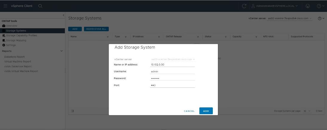
Step 9. Wait for the Storage Systems to update. You might need to click Refresh to complete this update.
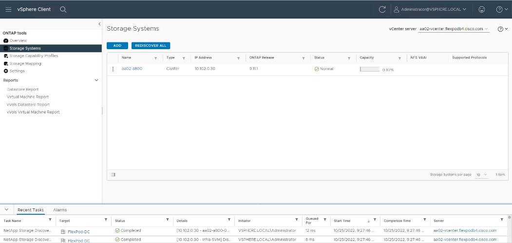
Step 10. From the vSphere Client Home page, click Hosts and Clusters.
Step 11. Right-click the FlexPod-DC datacenter, click NetApp ONTAP tools > Update Host and Storage Data.
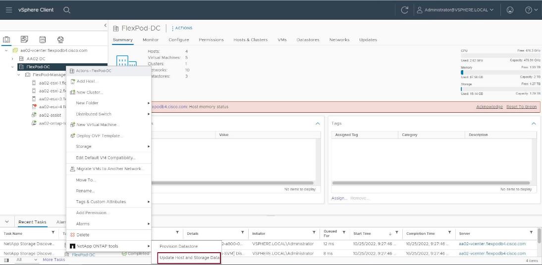
Step 12. On the Confirmation dialog box, click OK. It might take a few minutes to update the data.
Procedure 5. Optimal Storage Settings for ESXi Hosts
Note: NetApp ONTAP tools enables the automated configuration of storage-related settings for all ESXi hosts that are connected to NetApp storage controllers.
Step 1. From the VMware vSphere Web Client Home page, click vCenter > Hosts and Clusters.
Step 2. Select a host and then click Actions > NetApp ONTAP tools > Set Recommended Values.
Step 3. In the NetApp Recommended Settings dialog box, select all the applicable values for the ESXi host.
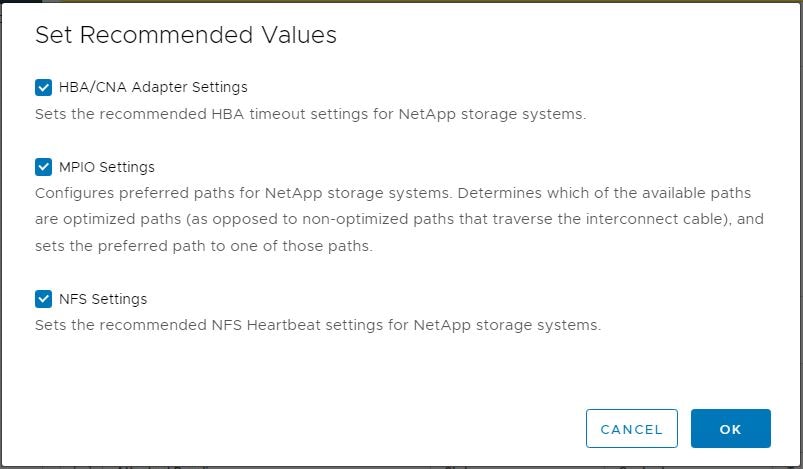
Note: This functionality sets values for HBAs and converged network adapters (CNAs), sets appropriate paths and path-selection plug-ins, and verifies appropriate settings for NFS I/O. A vSphere host reboot may be required after applying the settings.
Step 4. Click OK.
Provision Datastores using NetApp ONTAP Tools (Optional)
Using NetApp ONTAP tools, the administrator can provision an NFS, FC, FC-NVMe or iSCSI datastore and attach it to a single or multiple hosts in the cluster. The following steps describe provisioning a datastore and attaching it to the cluster.
Note: It is a NetApp best practice to use NetApp ONTAP tools to provision any additional datastores for the FlexPod infrastructure. When using VSC to create vSphere datastores, all NetApp storage best practices are implemented during volume creation and no additional configuration is needed to optimize performance of the datastore volumes.
Storage Capabilities
A storage capability is a set of storage system attributes that identifies a specific level of storage performance (storage service level), storage efficiency, and other capabilities such as encryption for the storage object that is associated with the storage capability.
Create the Storage Capability Profile
In order to leverage the automation features of VASA two primary components must first be configured. The Storage Capability Profile (SCP) and the VM Storage Policy. The Storage Capability Profile expresses a specific set of storage characteristics into one or more profiles used to provision a Virtual Machine. The SCP is specified as part of VM Storage Policy. NetApp ONTAP tools comes with several pre-configured SCPs such as Platinum, Bronze, and so on.
Note: The NetApp ONTAP tools for VMware vSphere plug-in also allows you to set Quality of Service (QoS) rule using a combination of maximum and/or minimum IOPs.
Procedure 1. Review or Edit the Built-In Profiles Pre-Configured with NetApp ONTAP Tools
Step 1. From the vCenter console, click Menu > ONTAP tools.
Step 2. In the NetApp ONTAP tools click Storage Capability Profiles.
Step 3. Select the Platinum Storage Capability Profile and select Clone from the toolbar.
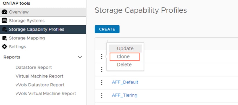
Step 4. Enter a name for the cloned SCP (for example, AFF_Platinum_Encrypted) and add a description if desired. Click NEXT.
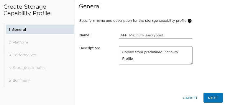
Step 5. Select All Flash FAS(AFF) for the storage platform and click NEXT.
Step 6. Select None to allow unlimited performance or set the desired minimum and maximum IOPS for the QoS policy group. Click NEXT.
Step 7. On the Storage attributes page, change the Encryption and Tiering policy to the desired settings and click NEXT. In the example below, Encryption was enabled.
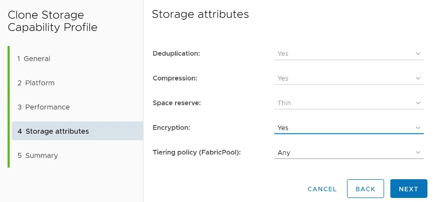
Step 8. Review the summary page and click FINISH to create the storage capability profile.
Note: It is recommended to Clone the Storage Capability Profile if you wish to make any changes to the predefined profiles rather than editing the built-in profile.
Procedure 2. Create a VM Storage Policy
Note: You must create a VM storage policy and associate SCP to the datastore that meets the requirements defined in the SCP.
Step 1. From the vCenter console, click Menu > Policies and Profiles.
Step 2. Select VM Storage Policies and click CREATE.
Step 3. Create a name for the VM storage policy and enter a description and click NEXT.
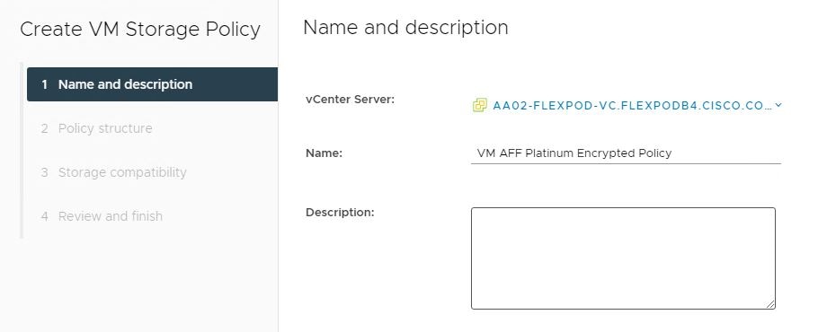
Step 4. Select Enable rules for NetApp.clustered.Data.ONTAP.VP.VASA10 storage located under the Datastore specific rules section and click NEXT.
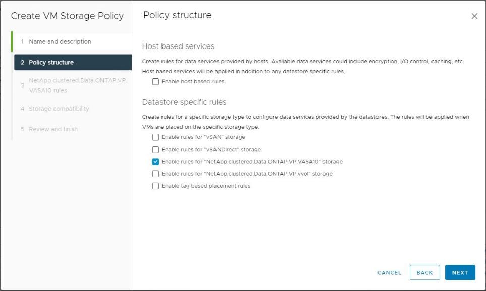
Step 5. On the Placement tab select the SCP created in the previous step and click NEXT.
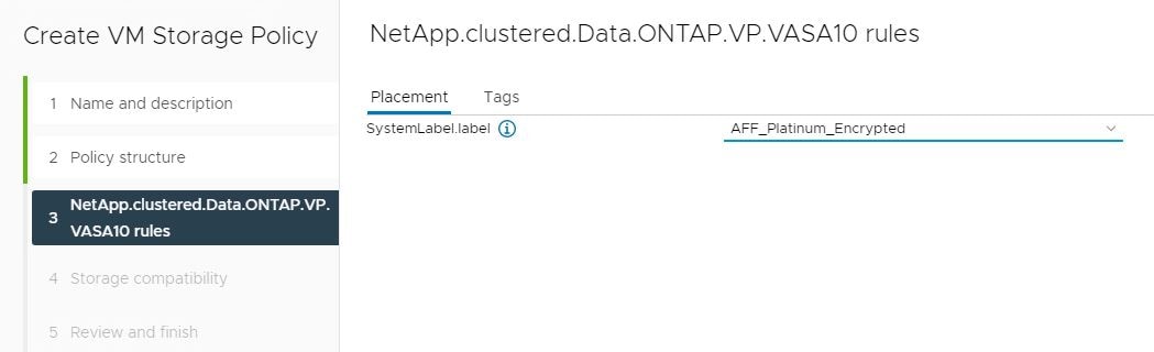
Step 6. All the datastores with matching capabilities are displayed, click NEXT.
Step 7. Review the policy summary and click FINISH.
Procedure 3. Provision NFS Datastore
Step 1. From the vCenter console, click Menu > ONTAP tools.
Step 2. From the NetApp ONTAP tools Home page, click Overview.
Step 3. In the Getting Started tab, click Provision.
Step 4. Click Browse to select the destination to provision the datastore.
Step 5. Select the type as NFS and Enter the datastore name (for example, NFS_DS_1).
Step 6. Provide the size of the datastore and the NFS Protocol.
Step 7. Check the storage capability profile and click NEXT.
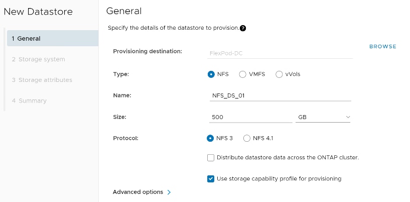
Step 8. Select the desired Storage Capability Profile, cluster name and the desired SVM to create the datastore. In this example, the Infra-SVM is selected.
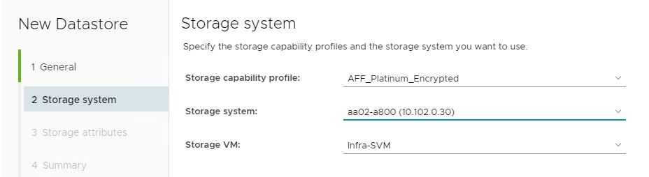
Step 9. Click NEXT.
Step 10. Select the aggregate name and click NEXT.
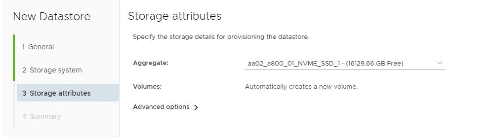
Step 11. Review the Summary and click FINISH.
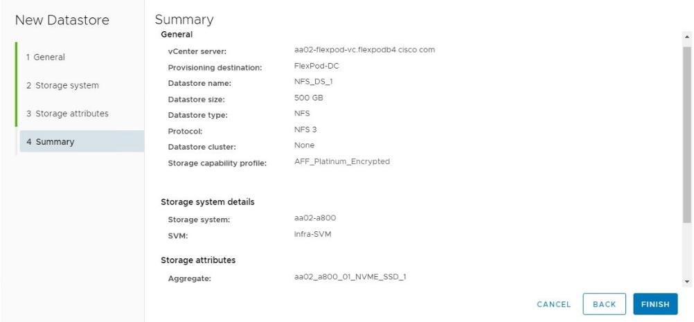
Step 12. The datastore is created and mounted on the hosts in the cluster. Click Refresh from the vSphere Web Client to see the newly created datastore.
Step 13. Distributed datastore is supported from NetApp ONTAP 9.8, which provides FlexGroup volume on NetApp ONTAP storage. To create a Distributed Datastore across the NetApp ONTAP Cluster select NFS 4.1 and check the box for Distributed Datastore data across the NetApp ONTAP Cluster as shown below.
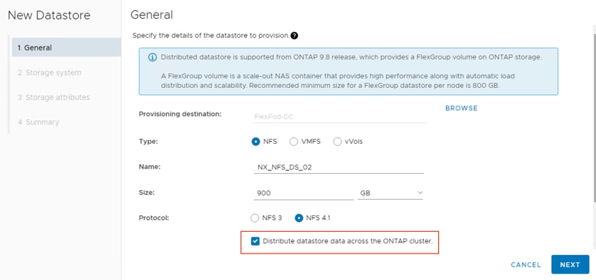
Procedure 4. Provision FC Datastore
Step 1. From the vCenter console, click Menu > ONTAP tools.
Step 2. From the NetApp ONTAP tools Home page, click Overview.
Step 3. In the Getting Started tab, click Provision.
Step 4. Click Browse to select the destination to provision the datastore.
Step 5. Select the type as VMFS and Enter the datastore name.
Step 6. Provide the size of the datastore and the FC Protocol.
Step 7. Check the Use storage capability profile and click NEXT.
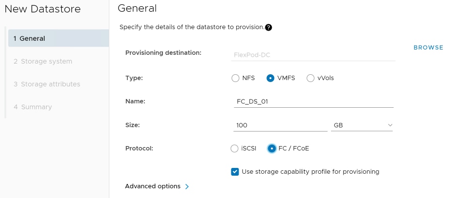
Step 8. Select the Storage Capability Profile, Storage System, and the desired Storage VM to create the datastore.
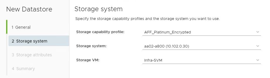
Step 9. Click NEXT.
Step 10. Select the aggregate name and click NEXT.
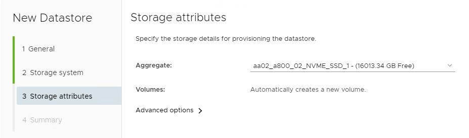
Step 11. Review the Summary and click FINISH.
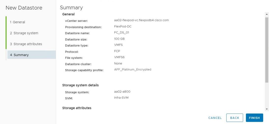
Step 12. The datastore is created and mounted on all the hosts in the cluster. Click Refresh from the vSphere Web Client to see the newly created datastore.
Procedure 5. Create Virtual Machine with Assigned VM Storage Policy
Step 1. Log into vCenter and navigate to the VMs and Templates tab and click to select the datacenter (for example, FlexPod-DC).
Step 2. Click Actions and click New Virtual Machine.
Step 3. Click Create a new virtual machine and click NEXT.
Step 4. Enter a name for the VM and select the datacenter (for example, FlexPod-DC).
Step 5. Select the cluster (for example, AA17-Cluster) and click NEXT.
Step 6. Select the VM storage policy from the selections and select a compatible datastore. Click NEXT.
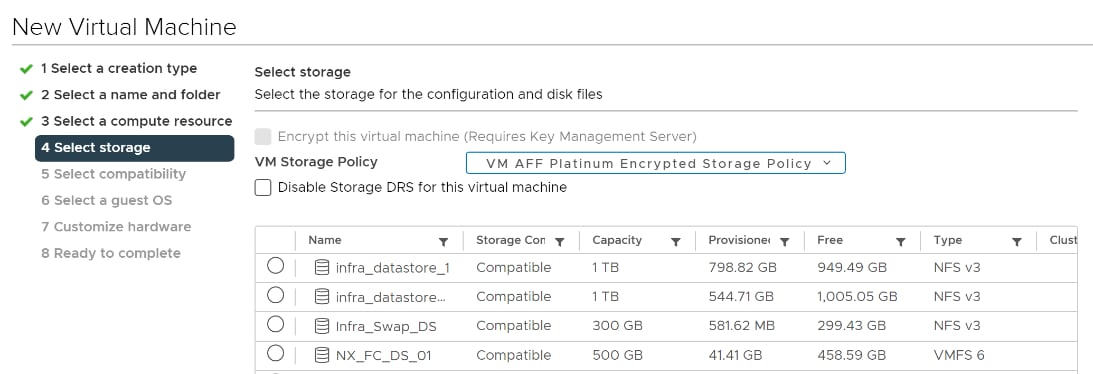
Step 7. Select Compatibility (for example, ESXi 7.0 U2 or later) and click NEXT.
Step 8. Select the Guest OS and click NEXT.
Step 9. Customize the hardware for the VM and click NEXT.
Step 10. Review the details and click FINISH.
Note: By selecting the VM storage policy in Step 6, the VM will be deployed on the compatible datastores.
Virtual Volumes – vVol (Optional)
NetApp VASA Provider enables customers to create and manage VMware virtual volumes (vVols). A vVols datastore consists of one or more FlexVol volumes within a storage container (also called "backing storage"). A virtual machine can be spread across one vVols datastore or multiple vVols datastores. All of the FlexVol volumes within the storage container must use the same protocol (NFS, iSCSI, or FCP) and the same SVMs.
For more information on vVOL datastore configuration, see: https://www.cisco.com/c/en/us/td/docs/unified_computing/ucs/UCS_CVDs/flexpod_xseries_vmware_7u2.html#VirtualVolumesvVolOptional
NetApp SnapCenter Plug-in 4.7 Installation
SnapCenter Software is a centralized and scalable platform that provides application-consistent data protection for applications, databases, host file systems, and VMs running on NetApp ONTAP systems anywhere in the Hybrid Cloud.
NetApp SnapCenter Architecture
The SnapCenter platform is based on a multitier architecture that includes a centralized management server (SnapCenter Server) and a SnapCenter host agent. The host agent that performs virtual machine and datastore backups for VMware vSphere is the SnapCenter Plug-in for VMware vSphere. It is packaged as a Linux appliance (Debian-based Open Virtual Appliance format) and is no longer part of the SnapCenter Plug-ins Package for Windows. Additional information on deploying SnapCenter server for application backups can be found in the documentation listed below.
This guide focuses on deploying and configuring the SnapCenter plug-in for VMware vSphere to protect virtual machines and VM datastores.
Note: You must install SnapCenter Server and the necessary plug-ins to support application-consistent backups for Microsoft SQL, Microsoft Exchange, Oracle databases and SAP HANA. Application-level protection is beyond the scope of this deployment guide.
Note: Refer to the SnapCenter documentation for more information or the application specific CVD’s and technical reports for detailed information on how to deploy SnapCenter for a specific application configuration:
● SnapCenter Documentation: https://docs.netapp.com/us-en/snapcenter/index.html
● Deploy FlexPod Datacenter for Microsoft SQL Server 2019 with VMware 7.0 on Cisco UCS B200 M6 and NetApp ONTAP 9.8:
https://www.cisco.com/c/en/us/products/collateral/servers-unified-computing/ucs-b-series-blade-servers/flexpod-sql-2019-vmware-on-ucs-netapp-ontap-wp.html
● SnapCenter Plug-in for VMware vSphere Documentation: SnapCenter Plug-in for VMware vSphere documentation (netapp.com)
Host and Privilege Requirements for the SnapCenter Plug-In for VMware vSphere
Review the following requirements before installing the SnapCenter Plug-in for VMware vSphere virtual appliance:
● SnapCenter Plug-in for VMware vSphere is deployed as a Linux based virtual appliance.
● Virtual appliance must not be deployed in a folder name with special characters.
● A separate, unique instance of the virtual appliance must be deployed for each vCenter Server.
| Port |
Requirement |
| 8080(HTTPS) bidirectional |
This port is used to manage the virtual appliance |
| 8144(HTTPs) bidirectional |
Communication between SnapCenter Plug-in for VMware vSphere and vCenter |
| 443 (HTTPS) |
Communication between SnapCenter Plug-in for VMware vSphere and vCenter |
License Requirements for SnapCenter Plug-In for VMware vSphere
The licenses listed in Table 17 are required on the NetApp ONTAP storage system to backup and restore VM’s in the virtual infrastructure:
Table 17. SnapCenter Plug-in for VMware vSphere License Requirements
| Product |
License Requirements |
| NetApp ONTAP |
SnapManager Suite: Used for backup operations One of these: SnapMirror or SnapVault (for secondary data protection regardless of the type of relationship) |
| NetApp ONTAP Primary Destinations |
To perform protection of VMware VMs and datastores the following licenses should be installed: SnapRestore: used for restoring operations FlexClone: used for mount and attach operations |
| NetApp ONTAP Secondary Destinations |
To perform protection of VMware VMs and datastores only: FlexClone: used for mount and attach operations |
| VMware |
vSphere Standard, Enterprise, or Enterprise Plus A vSphere license is required to perform restore operations, which use Storage vMotion. vSphere Essentials or Essentials Plus licenses do not include Storage vMotion. |
Note: It is recommended (but not required) to add SnapCenter Standard licenses to secondary destinations. If SnapCenter Standard licenses are not enabled on secondary systems, SnapCenter cannot be used after a failover operation. A FlexClone license on secondary storage is required to perform mount and attach operations. A SnapRestore license is required to perform restore operations.
Procedure 1. Manually Deploy the SnapCenter Plug-In for VMware vSphere 4.7
Step 1. Download SnapCenter Plug-in for VMware vSphere OVA file from NetApp support site (https://mysupport.netapp.com).
Step 2. From VMware vCenter, navigate to the VMs and Templates tab, right-click the data center (for example, FlexPod-DC) and select Deploy OVF Template.
Step 3. Specify the location of the OVF Template and click NEXT.
Step 4. On the Select a name and folder page, enter a unique name (for example, aa02-scv) and location (data center for example, FlexPod-DC) for the VM and click NEXT to continue.
Step 5. On the Select a compute resource page, select the cluster, and click NEXT.
Step 6. On the Review details page, verify the OVA template details and click NEXT.
Step 7. On the License agreements page, read and check the box I accept all license agreements. Click NEXT.
Step 8. On the Select storage page, select a datastore, change the datastore virtual disk format to Thin Provision and click NEXT.
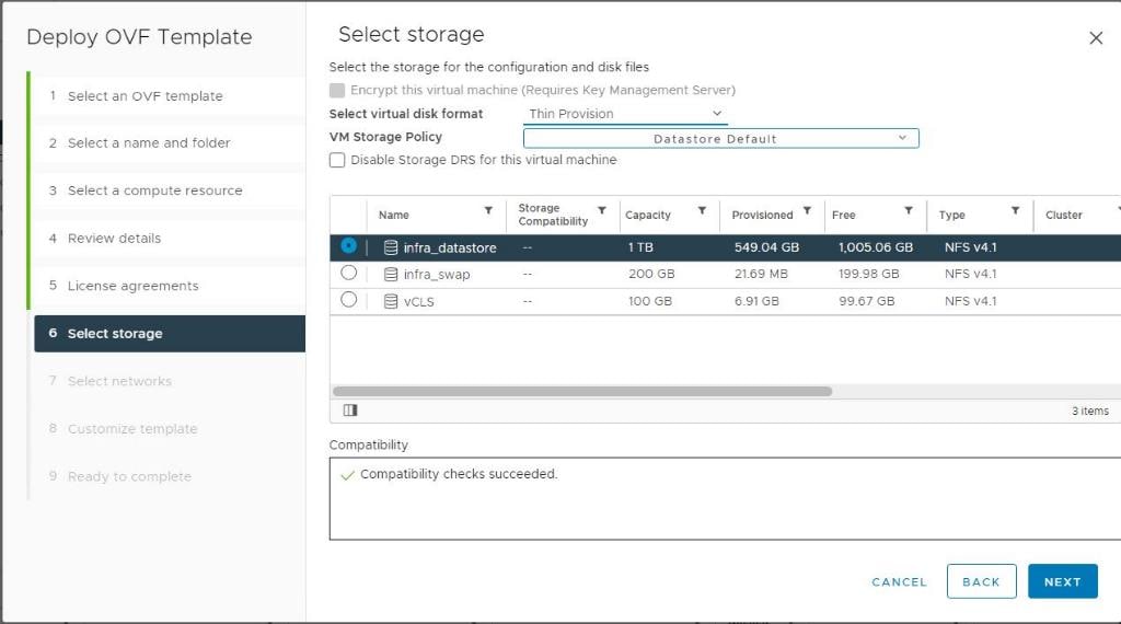
Step 9. On the Select networks page, select a destination network for example, IB-MGMT and then click NEXT.
Step 10. On the Customize template page, under Register to existing vCenter, enter the vCenter credentials.
Step 11. In Create SCV credentials, create a username (for example, admin) and password.
Step 12. In System Configuration, enter the maintenance user password.
Step 13. In Setup Network Properties, enter the network information.
Step 14. In Setup Date and Time, provide the NTP server address(es) and select the time zone where the vCenter is located.
Step 15. Click NEXT.
Step 16. On the Ready to complete page, review the page and click FINISH. The VM deployment will start. After the VM is deployed successfully, proceed to the next step.
Step 17. Navigate to the SnapCenter VM, right-click, and select Power > Power On to start the virtual appliance.
Step 18. While the virtual appliance is powering on, click Install VMware tools.
Step 19. After the SnapCenter VM installation is complete and VM is ready to use, proceed to the next step.
Step 20. Log into SnapCenter Plug-in for VMware vSphere using the IP address (https://<ip_address_of_SnapCenter>:8080 ) displayed on the appliance console screen with the credentials that you provided in the deployment wizard.
Step 21. Verify on the Dashboard that the virtual appliance has successfully connected to vCenter and the SnapCenter Plug-in for VMware vSphere is successfully enabled and connected.
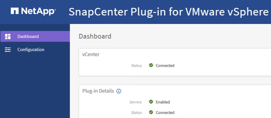
NetApp SnapCenter Plug-in 4.7 Configuration
Procedure 1. SnapCenter Plug-In for VMware vSphere in vCenter Server
Step 1. Navigate to VMware vSphere Web Client URL https://<vCenter Server>
Note: If you’re currently logged into vCenter, logoff, close the open tab and sign-on again to access the newly installed SnapCenter Plug-in for VMware vSphere.
Step 2. After logging on, a blue banner will be displayed indicating the SnapCenter plug-in was successfully deployed. Click Refresh to activate the plug-in.
Step 3. On the VMware vSphere Web Client page, select Menu > SnapCenter Plug-in for VMware vSphere to launch the SnapCenter Plug-in for VMware GUI.
Procedure 2. Add Storage System
Step 1. Click Storage Systems.
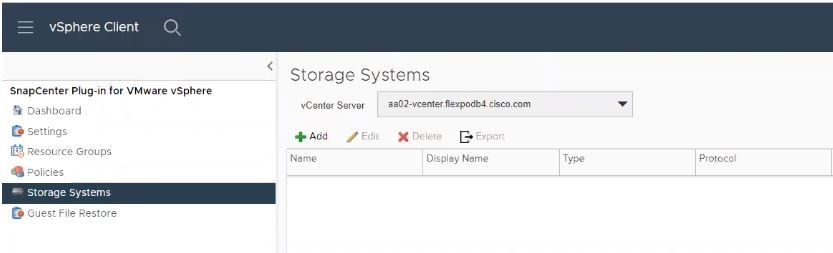
Step 2. Click +Add to add a storage system (or SVM).
Step 3. Enter Storage System, user credentials, and other required information in following dialog box.
Step 4. Check the box for Log SnapCenter server events to syslog and Send AutoSupport Notification for failed operation to storage system.
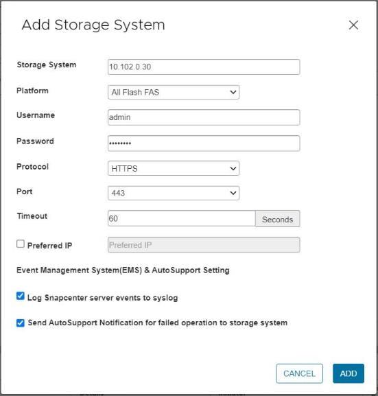
Step 5. Click ADD.

When the storage system is added, you can create backup policies and take scheduled backup of VMs and datastores. The SnapCenter plug-in for VMware vSphere allows backup, restore and on-demand backups.
For more information on backup policy configuration, refer to this CVD: https://www.cisco.com/c/en/us/td/docs/unified_computing/ucs/UCS_CVDs/flexpod_xseries_vmware_7u2.html#FlexPodManagementToolsSetup
Active IQ Unified Manager 9.11P1 Installation
Active IQ Unified Manager enables you to monitor and manage the health and performance of NetApp ONTAP storage systems and virtual infrastructure from a single interface. Unified Manager provides a graphical interface that displays the capacity, availability, protection, and performance status of the monitored storage systems. Active IQ Unified Manager is required to integrate NetApp storage with Cisco Intersight.
This subject describes the steps to deploy NetApp Active IQ Unified Manager 9.11P1 as a virtual appliance. Table 18 lists the recommended configuration for the VM.
Table 18. Virtual Machine Configuration
| Hardware Configuration |
Recommended Settings |
| RAM |
12 GB |
| Processors |
4 CPUs |
| CPU Cycle Capacity |
9572 MHz total |
| Free Disk Space/virtual disk size |
5 GB - Thin provisioned 152 GB – Thick provisioned |
Note: There is a limit to the number of nodes that a single instance of Active IQ Unified Manager can monitor before a second instance of Active IQ Unified Manager is needed. See the Unified Manager Best Practices Guide (TR-4621) for more details.
Procedure 1. Install NetApp Active IQ Unified Manager 9.11P1 Manually
Step 1. Download NetApp Active IQ Unified Manager for VMware vSphere OVA file from: https://mysupport.netapp.com/site/products/all/details/activeiq-unified-manager/downloads-tab.
Step 2. In the VMware vCenter GUI, click VMs and Templates and then click Actions> Deploy OVF Template.
Step 3. Specify the location of the OVF Template and click NEXT.
Step 4. On the Select a name and folder page, enter a unique name for the VM, and select a deployment location, and then click NEXT.
Step 5. On the Select a compute resource screen, select the cluster where VM will be deployed and click NEXT.
Step 6. On the Review details page, verify the OVA template details and click NEXT.
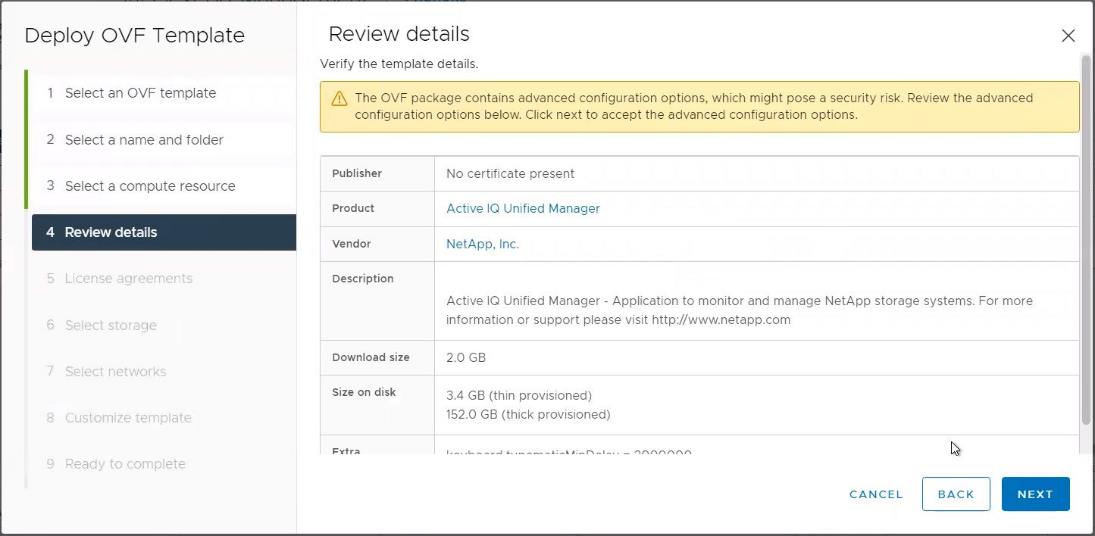
Step 7. On the License agreements page, read and check the box for I accept all license agreements. Click NEXT.
Step 8. On the Select storage page, select following parameters for the VM deployment:
a. Select the disk format for the VMDKs (for example, Thin Provisioning).
b. Select a VM Storage Policy (for example, Datastore Default).
c. Select a datastore to store the deployed OVA template.
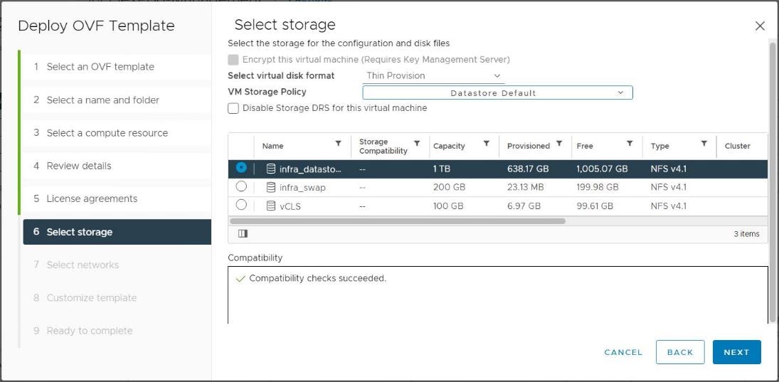
Step 9. Click NEXT.
Step 10. On the Select networks page, select the destination network (for example, IB-MGMT) and click NEXT.
Step 11. On the Customize template page, provide network details such as hostname, IP address, gateway, and DNS.
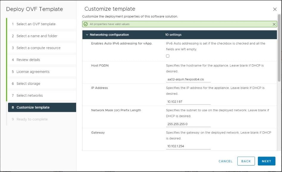
Step 12. Leave TimeZone value field blank but enter Maintenance username and password.
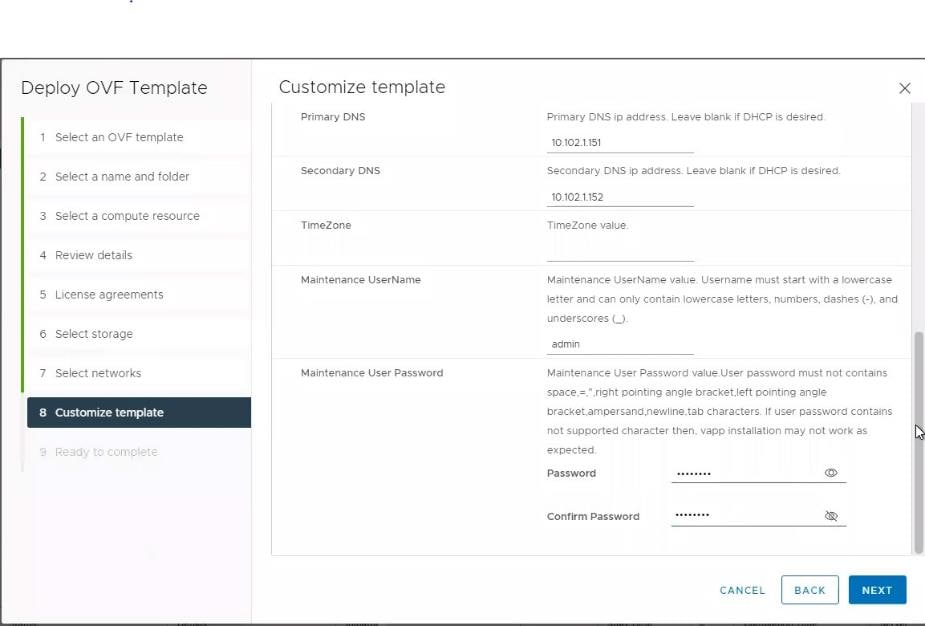
Note: Save the maintenance user account credentials in a secure location. These credentials will be used for the initial GUI login and to make any configuration changes to the appliance settings in future
Step 13. Click NEXT.
Step 14. On the Ready to complete page, review the settings and click FINISH. Wait for the VM deployment to complete before proceeding to the next step.
Step 15. Select the newly created Active IQ Unified Manager VM, right-click and select Power > Power On.
Step 16. While the virtual machine is powering on, click the prompt in the yellow banner to Install VMware tools.
Note: Because of timing, VMware tools might not install correctly. In that case VMware tools can be manually installed after Active IQ Unified Manager VM is up and running.
Step 17. Open the VM console for the Active IQ Unified Manager VM and configure the time zone information when displayed.
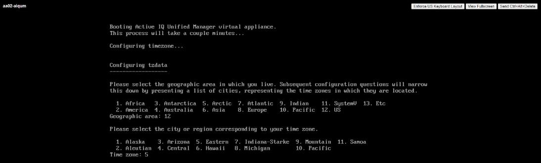
Step 18. Wait for the AIQM web console to display the login prompt.
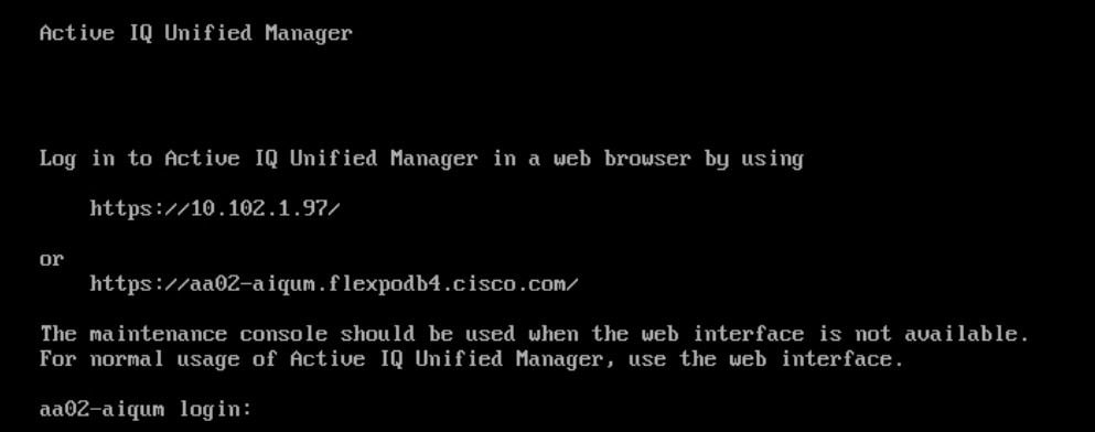
Step 19. Log into NetApp Active IQ Unified Manager using the IP address or URL displayed on the web console.
Configure Active IQ Unified Manager
Procedure 1. Initial Setup
Step 1. Launch a web browser and log into Active IQ Unified Manger using the URL shown in the VM console.
Step 2. Enter the email address that Unified Manager will use to send alerts and the mail server configuration. Click Continue.
Step 3. Select Agree and Continue on the Set up AutoSupport configuration.
Step 4. Check the box for Enable API Gateway and click Continue.
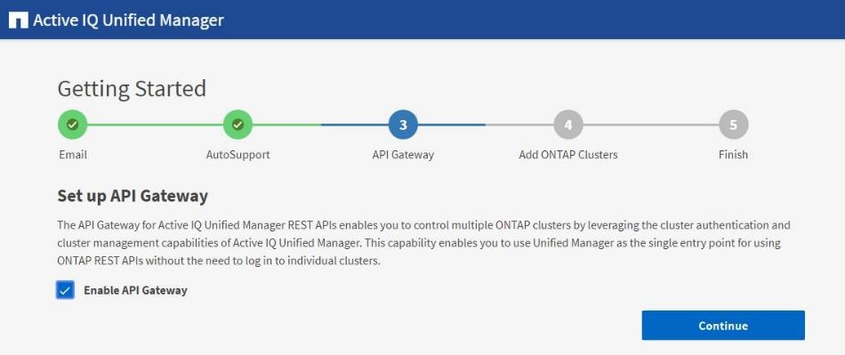
Step 5. Enter the NetApp ONTAP cluster hostname or IP address and the admin login credentials.
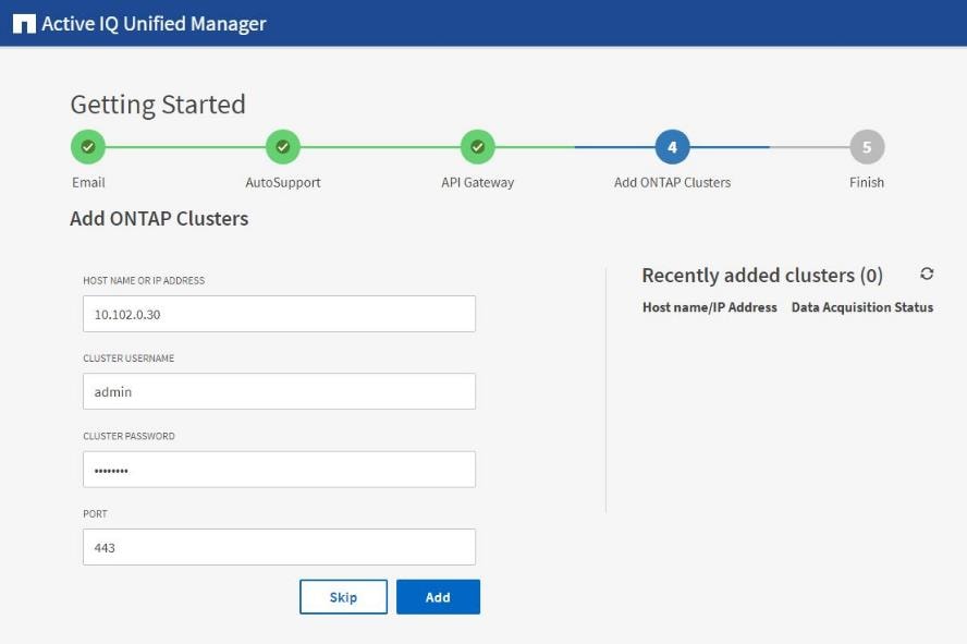
Step 6. Click Add.
Step 7. Click Yes to trust the self-signed cluster certificate and finish adding the storage system.
Note: The initial discovery process can take up to 15 minutes to complete.
Procedure 2. Review Security Compliance with Active IQ Unified Manager
Active IQ Unified Manager identifies issues and makes recommendations to improve the security posture of NetApp ONTAP. Active IQ Unified Manager evaluates NetApp ONTAP storage based on recommendations made in the Security Hardening Guide for NetApp ONTAP 9. Items are identified according to their level of compliance with the recommendations. Review the Security Hardening Guide for NetApp ONTAP 9 (TR-4569) for additional information and recommendations for securing NetApp ONTAP 9.
Note: All events identified do not inherently apply to all environments, for example, FIPS compliance.
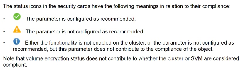
Step 8. Navigate to the URL of the Active IQ Unified Manager and login.
Step 9. Select the Dashboard from the left menu bar in Active IQ Unified Manager.
Step 10. Locate the Security card and note the compliance level of the cluster and SVM.
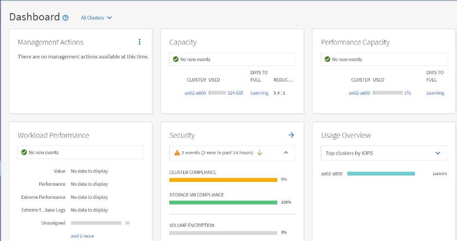
Step 11. Click the blue arrow to expand the findings.
Step 12. Locate Individual Cluster section and the Cluster Compliance card. From the drop-down list select View All.
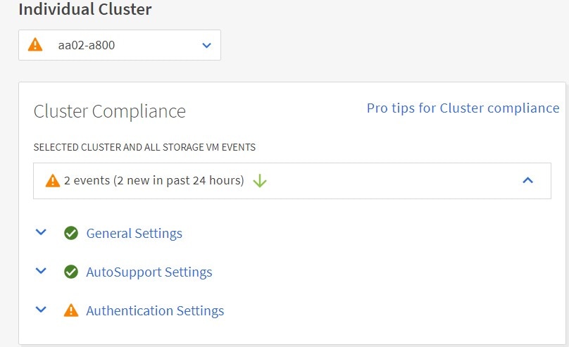
Step 13. Select an event from the list and click the name of the event to view the remediation steps.
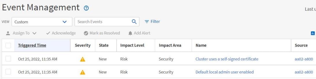
Step 14. Remediate the risk if applicable to current environment and perform the suggested actions to fix the issue.
Remediate Security Compliance Findings
Note: Active IQ identifies several security compliance risks after installation that can be immediately corrected to improve the security posture of NetApp ONTAP. Click on the event name to get more information and suggested actions to fix the issue.
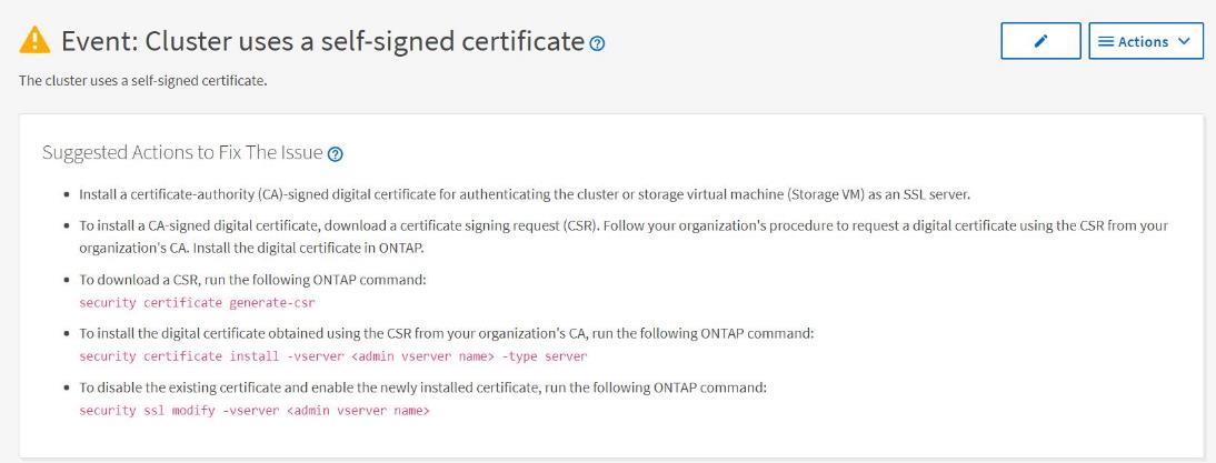
Deploy Cisco Intersight Assist Appliance
Cisco Intersight works with NetApp’s ONTAP storage and VMware vCenter using third-party device connectors and Cisco Nexus and MDS switches using Cisco device connectors. Since third-party infrastructure and Cisco switches do not contain any usable built-in Intersight device connector, Cisco Intersight Assist virtual appliance enables Cisco Intersight to communicate with these devices.
Note: A single Cisco Intersight Assist virtual appliance can support both NetApp ONTAP storage, VMware vCenter, and Cisco Nexus and MDS switches.
Figure 4. Managing NetApp and VMware vCenter through Cisco Intersight using Intersight Assist
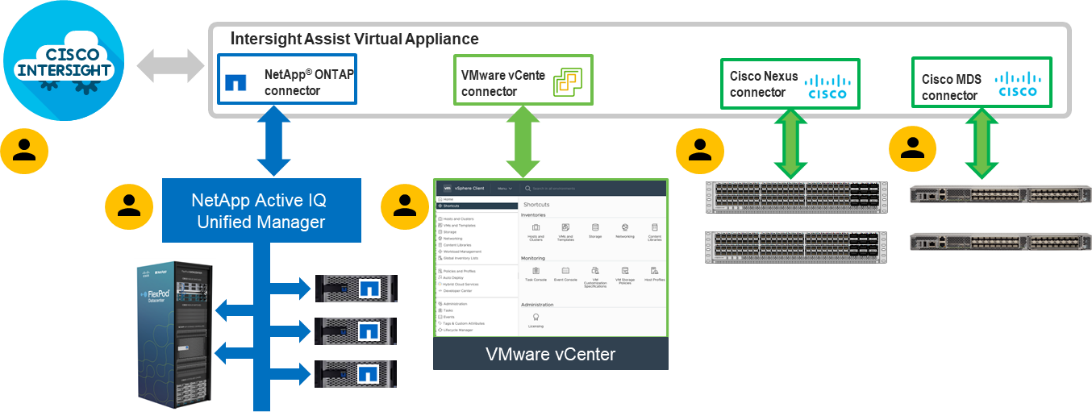
Procedure 1. Install Cisco Intersight Assist
Step 1. To install Cisco Intersight Assist from an Open Virtual Appliance (OVA), download the latest release of the Cisco Intersight Virtual Appliance for vSphere from https://software.cisco.com/download/home/286319499/type/286323047/release/1.0.9-499.
Note: It is important to install release 1.0.9-499 at a minimum.
Procedure 2. Set up DNS entries
Step 1. Setting up Cisco Intersight Virtual Appliance requires an IP address and 2 hostnames for that IP address. The hostnames must be in the following formats:
● myhost.mydomain.com: A hostname in this format is used to access the GUI. This must be defined as an A record and PTR record in DNS. The PTR record is required for reverse lookup of the IP address. If an IP address resolves to multiple hostnames, the first one in the list is used.
● dc-myhost.mydomain.com: The dc- must be prepended to your hostname. This hostname must be defined as the CNAME of myhost.mydomain.com. Hostnames in this format are used internally by the appliance to manage device connections.
Step 2. In this lab deployment the following information was used to deploy a Cisco Intersight Assist VM:
● Hostname: aa02-assist.flexpodb4.cisco.com
● IP address: 10.102.1.96
● DNS Entries (Windows AD/DNS):
◦ A Record
![]()
◦ CNAME:
![]()
◦ PTR (reverse lookup):
![]()
For more information, refer to: https://www.cisco.com/c/en/us/td/docs/unified_computing/Intersight/b_Cisco_Intersight_Appliance_Getting_Started_Guide/b_Cisco_Intersight_Appliance_Install_and_Upgrade_Guide_chapter_00.html.
Procedure 3. Deploy Cisco Intersight OVA
Note: Ensure that the appropriate entries of type A, CNAME, and PTR records exist in the DNS, as explained in the previous section. Log into the vSphere Client and select Hosts and Clusters.
Step 1. From Hosts and Clusters, right-click the cluster and click Deploy OVF Template.
Step 2. Select Local file and click UPLOAD FILES. Browse to and select the intersight-appliance-installer-vsphere-1.0.9-342.ova or the latest release file and click Open. Click NEXT.
Step 3. Name the Intersight Assist VM and select the location. Click NEXT.
Step 4. Select the cluster and click NEXT.
Step 5. Review details, click Ignore All, and click NEXT.
Step 6. Select a deployment configuration. If only the Intersight Assist functionality is needed, a deployment size of Tiny can be used. If Intersight Workload Optimizer (IWO) is being used in this Intersight account, use the Small deployment size. Click NEXT.
Step 7. Select the appropriate datastore (for example, infra_datastore) for storage and select the Thin Provision virtual disk format. Click NEXT.
Step 8. Select appropriate management network (for example, IB-MGMT Network) for the OVA. Click NEXT.
Note: The Cisco Intersight Assist VM must be able to access both the IB-MGMT network on FlexPod and Intersight.com. Select and configure the management network appropriately. If selecting IB-MGMT network on FlexPod, make sure the routing and firewall is setup correctly to access the Internet.
Step 9. Fill in all values to customize the template. Click NEXT.
Step 10. Review the deployment information and click FINISH to deploy the appliance.
Step 11. When the OVA deployment is complete, right-click the Intersight Assist VM and click Edit Settings.
Step 12. Expand CPU and verify the socket configuration. For example, in the following deployment, on a 2-socket system, the VM was configured for 16 sockets:
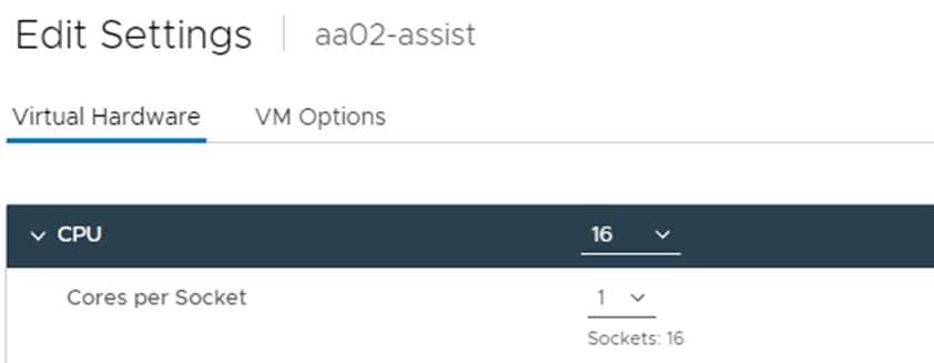
Step 13. Adjust the Cores per Socket so that the number of Sockets matches the server CPU configuration (2 sockets in this deployment):
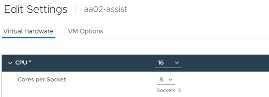
Step 14. Click OK.
Step 15. Right-click the Intersight Assist VM and select Power > Power On.
Step 16. When the VM powers on and login prompt is visible (use remote console), connect to https://intersight-assist-fqdn.
Note: It may take a few minutes for https://intersight-assist-fqdn to respond.
Step 17. Navigate the security prompts and select Intersight Assist. Click Start.
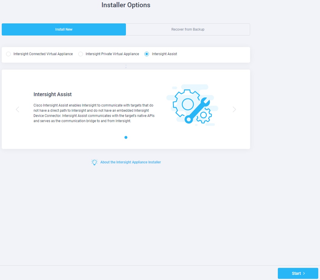
Step 18. Cisco Intersight Assist VM needs to be claimed in Cisco Intersight using the Device ID and Claim Code information visible in the GUI.
Step 19. Log into Cisco Intersight and connect to the appropriate account.
Step 20. From Cisco Intersight, at the top select System, then click Administration > Targets.
Step 21. Click Claim a New Target. Select Cisco Intersight Assist and click Start.
Step 22. Copy and paste the Device ID and Claim Code shown in the Intersight Assist web interface to the Cisco Intersight Device Claim window.
Step 23. Select the Resource Group and click Claim.
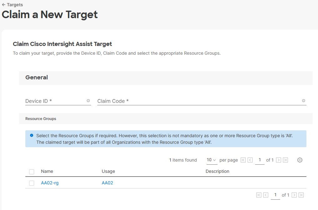
Step 24. Intersight Assist will now appear as a claimed device.
Step 25. In the Intersight Assist web interface, verify that Intersight Assist is Connected Successfully, and click Continue.
Note: The Cisco Intersight Assist software will now be downloaded and installed into the Intersight Assist VM. This can take up to an hour to complete.
Step 26. When the software download is complete, an Intersight Assist login screen will appear.
Step 27. Log into Intersight Assist with the admin user and the password supplied in the OVA installation. Check the Intersight Assist status and log out of Intersight Assist.
Claim VMware vCenter using Cisco Intersight Assist Appliance
Procedure 1. Claim the vCenter from Cisco Intersight
Step 1. Log into Cisco Intersight and connect to the account for this FlexPod.
Step 2. Select System > Administration > Targets and click Claim a New Target.
Step 3. Under Select Target Type, select VMware vCenter under Hypervisor and click Start.
Step 4. In the VMware vCenter window, verify the correct Intersight Assist is selected.
Step 5. Fill in the vCenter information. If Intersight Workflow Optimizer (IWO) will be used, turn on Datastore Browsing Enabled and Guest Metrics Enabled. If it is desired to use Hardware Support Manager (HSM) to be able to upgrade IMM server firmware from VMware Lifecycle Manager, turn on HSM. Click Claim.
Note: It is recommended to use an admin-level user other than administrator@vsphere.local to claim VMware vCenter to Intersight. The administrator@vsphere.local user has visibility to the vSphere Cluster Services (vCLS) virtual machines. These virtual machines would then be visible in Intersight and Intersight operations could be executed on them. VMware does not recommend users executing operations on these VMs. Using a user other than administrator@vsphere.local would make the vCLS virtual machines inaccessible from Cisco Intersight.
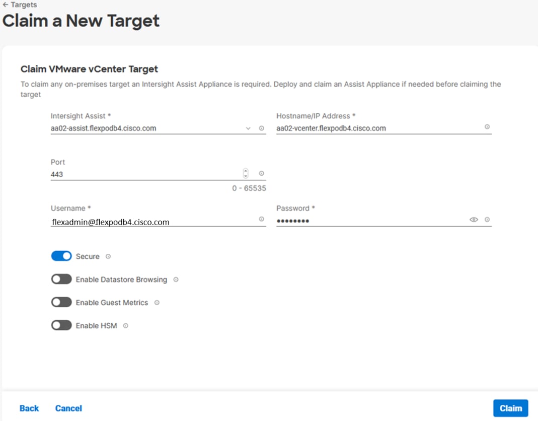
Step 6. After a few minutes, the VMware vCenter will show Connected in the Targets list and will also appear under Infrastructure Service > Operate > Virtualization.
Step 7. Detailed information obtained from the vCenter can now be viewed by clicking Infrastructure Service > Operate > Virtualization and selecting the Datacenters tab. Other VMware vCenter information can be obtained by navigating through the Virtualization tabs.
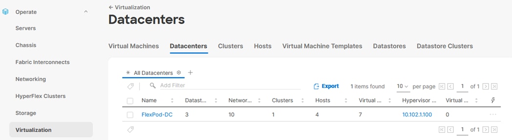
Procedure 2. Interact with Virtual Machines
VMware vCenter integration with Cisco Intersight allows you to directly interact with the virtual machines (VMs) from the Cisco Intersight dashboard. In addition to obtaining in-depth information about a VM, including the operating system, CPU, memory, host name, and IP addresses assigned to the virtual machines, you can use Cisco Intersight to perform the following actions on the virtual machines:
● Start/Resume
● Stop
● Soft Stop
● Suspend
● Reset
● Launch VM Console
Step 1. Log into Cisco Intersight and connect to the account for this FlexPod.
Step 2. Select Infrastructure Service > Operate > Virtualization.
Step 3. Click the Virtual Machines tab.
Step 4. Click “…” to the right of a VM and interact with various VM options.
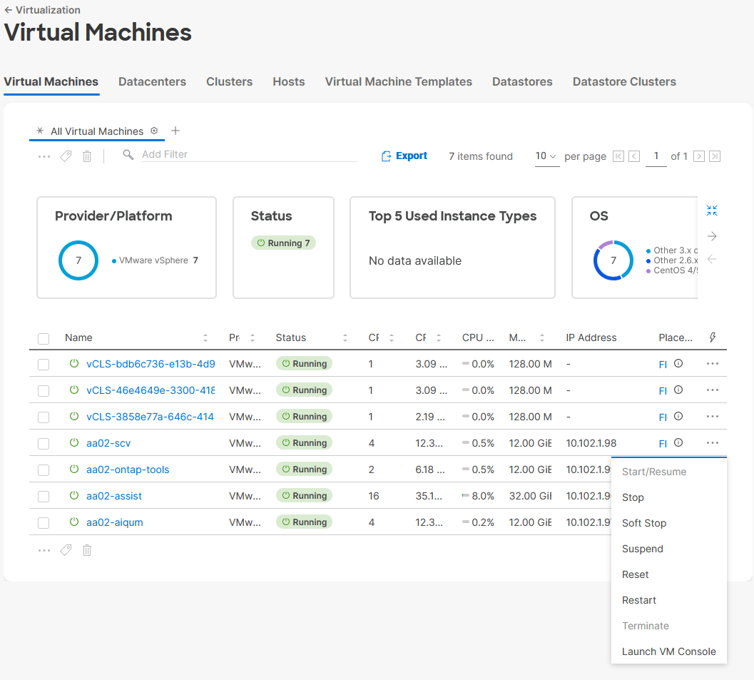
Step 5. To gather more information about a VM, click a VM name. The same interactive options are available under Actions.
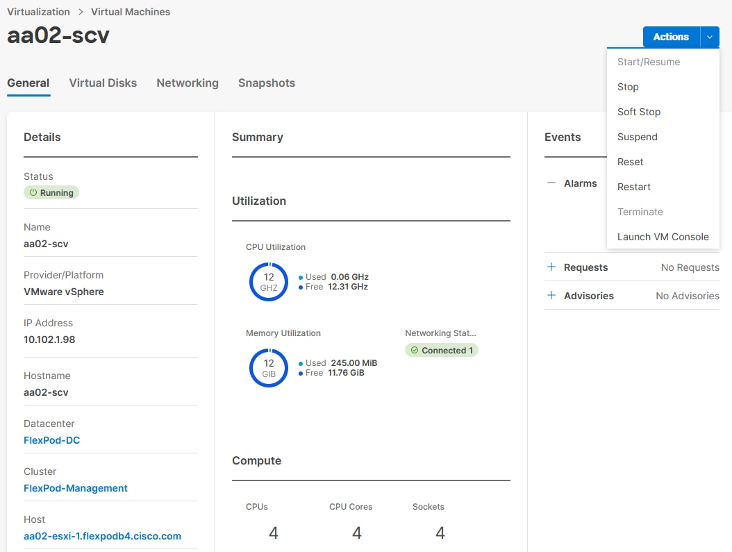
Claim NetApp Active IQ Manager using Cisco Intersight Assist Appliance
Procedure 1. Claim NetApp Active IQ Unified Manager into Cisco Intersight using Ansible
Step 1. Clone the repository from https://github.com/NetApp-Automation/NetApp-AIQUM.
Step 2. Follow the instructions in the README file in the repository to ensure the Ansible environment is configured properly.
Step 3. Update the variable files as mentioned in the README document in the repository.
Step 4. To claim an existing AIQUM instance into Intersight, invoke the below ansible playbook:
ansible-playbook aiqum.yml -t intersight_claim
Procedure 2. Manually Claim the NetApp Active IQ Unified Manager into Cisco Intersight
Step 1. Log into Cisco Intersight and connect to the account for this FlexPod.
Step 2. From Cisco Intersight, click System > Administration > Targets.
Step 3. Click Claim a New Target. In the Select Target Type window, select NetApp Active IQ Unified Manager under Storage and click Start.
Step 4. In the Claim NetApp Active IQ Unified Manager Target window, verify the correct Intersight Assist is selected.
Step 5. Fill in the NetApp Active IQ Unified Manager information and click Claim.
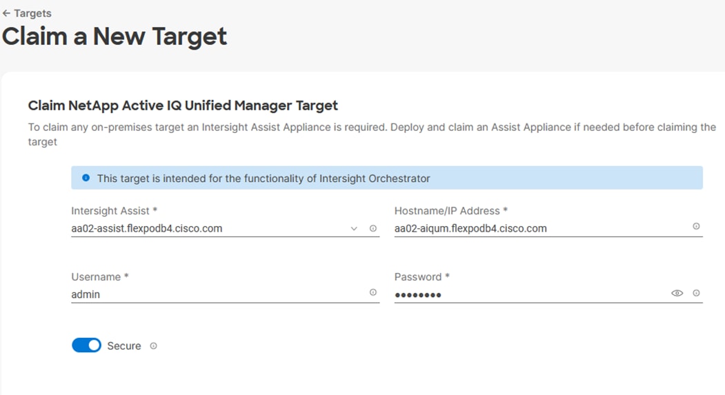
Step 6. After a few minutes, the NetApp ONTAP Storage configured in the Active IQ Unified Manager will appear under Infrastructure Service > Operate > Storage tab.
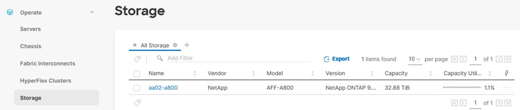
Step 7. Click the storage cluster name to see detailed General, Inventory, and Checks information on the storage.
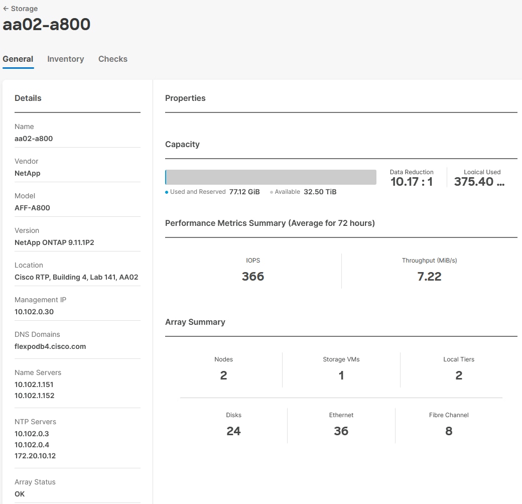
Step 8. Click My Dashboard > Storage to see storage monitoring widgets.
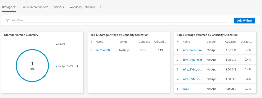
Claim Cisco Nexus Switches using Cisco Intersight Assist Appliance
Procedure 1. Claim Cisco Nexus Switches
Step 1. Log into Cisco Intersight and connect to the account for this FlexPod.
Step 2. From Cisco Intersight, click System > Administration > Targets.
Step 3. Click Claim a New Target. In the Select Target Type window, select Cisco Nexus Switch under Network and click Start.
Step 4. In the Claim Cisco Nexus Switch Target window, verify the correct Intersight Assist is selected.
Step 5. Fill in the Cisco Nexus Switch information and click Claim.
Note: You can use the admin user on the switch.
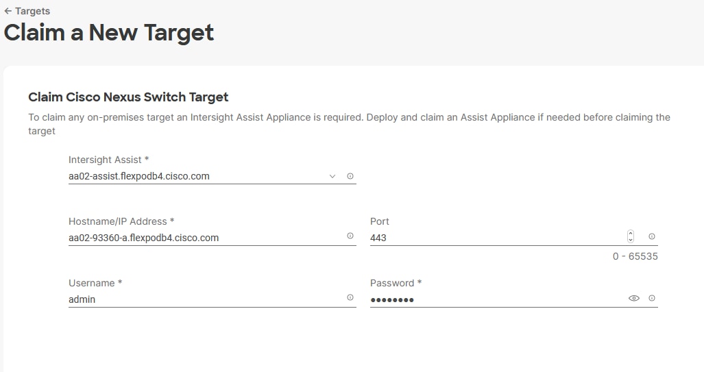
Step 6. Follow the steps in this procedure to add the second Cisco Nexus Switch.
Step 7. After a few minutes, the two switches will appear under Infrastructure Service > Operate > Networking > Ethernet Switches.
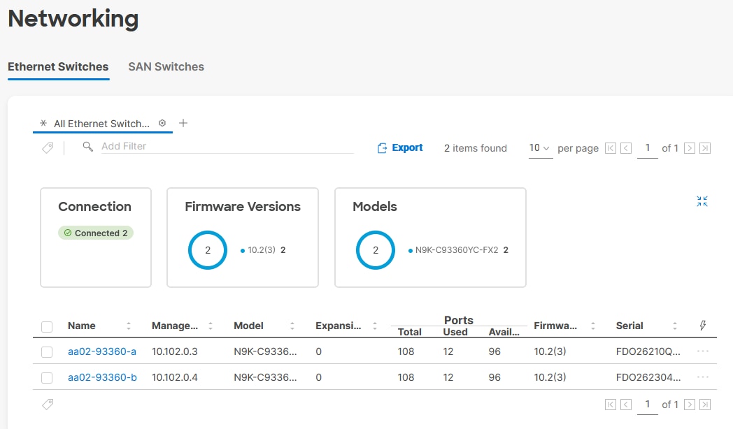
Step 8. Click one of the switch names to get detailed General and Inventory information on the switch.
Claim Cisco MDS Switches using Cisco Intersight Assist Appliance
Procedure 1. Claim Cisco MDS Switches (if they are part of the FlexPod)
Step 1. Log into Cisco Intersight and connect to the account for this FlexPod.
Step 2. From Cisco Intersight, click System > Administration > Targets.
Step 3. Click Claim a New Target. In the Select Target Type window, select Cisco MDS Switch under Network and click Start.
Step 4. In the Claim Cisco MDS Switch Target window, verify the correct Intersight Assist is selected.
Step 5. Fill in the Cisco MDS Switch information including use of Port 8443 and click Claim.
Note: You can use the admin user on the switch.
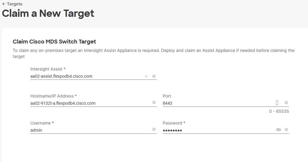
Step 6. Follow the steps in this procedure to add the second Cisco MDS Switch.
Step 7. After a few minutes, the two switches will appear under Infrastructure Service > Operate > Networking > SAN Switches.
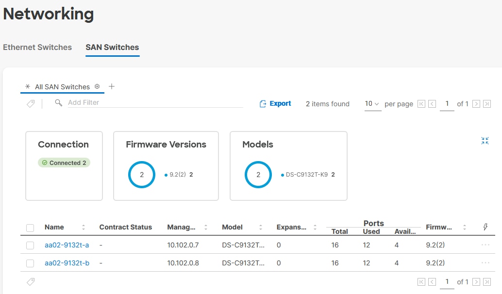
Step 8. Click one of the switch names to get detailed General and Inventory information on the switch.
Create a FlexPod XCS Integrated System
Procedure 1. Creating a FlexPod XCS Integrated System
Step 1. Log into Cisco Intersight and connect to the account for this FlexPod.
Step 2. From Cisco Intersight, click Infrastructure Service > Operate > Integrated Systems.
Step 3. Click Create Integrated System. In the center pane, select FlexPod and click Start.
Step 4. Select the correct Organization (for example, AA02), provide a suitable name, and optionally any Tags or a Description and click Next.
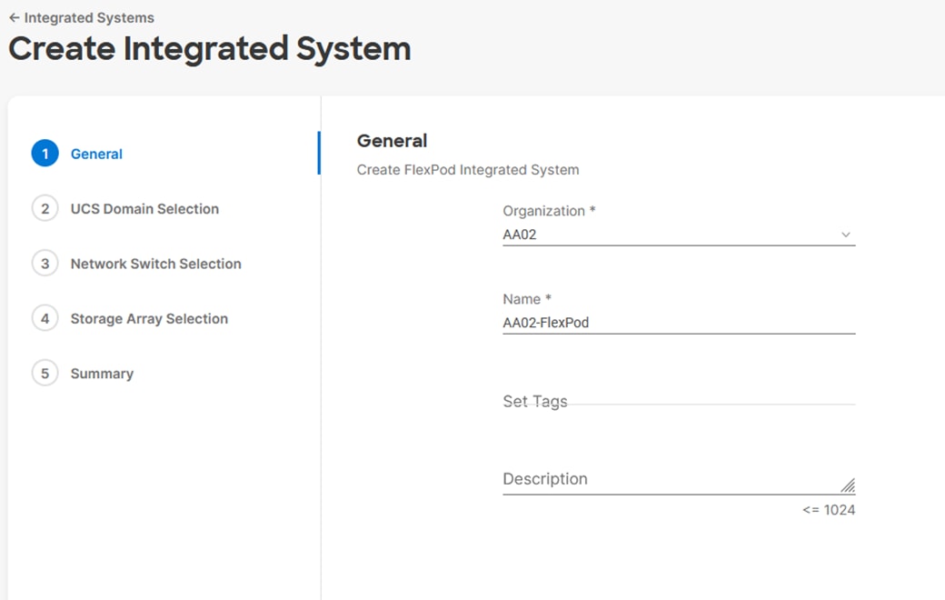
Step 5. Select the UCS Domain used in this FlexPod and click Next.
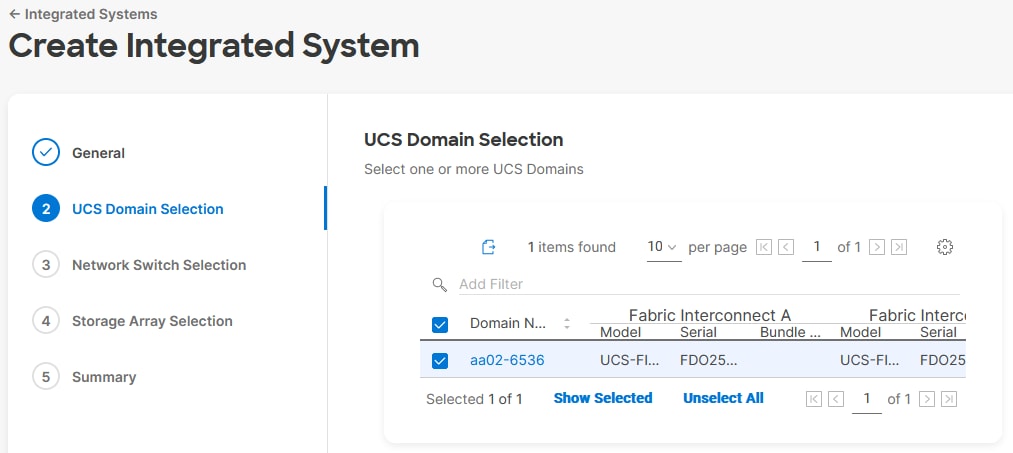
Step 6. Select the two Cisco Nexus switches used in this FlexPod and click Next.
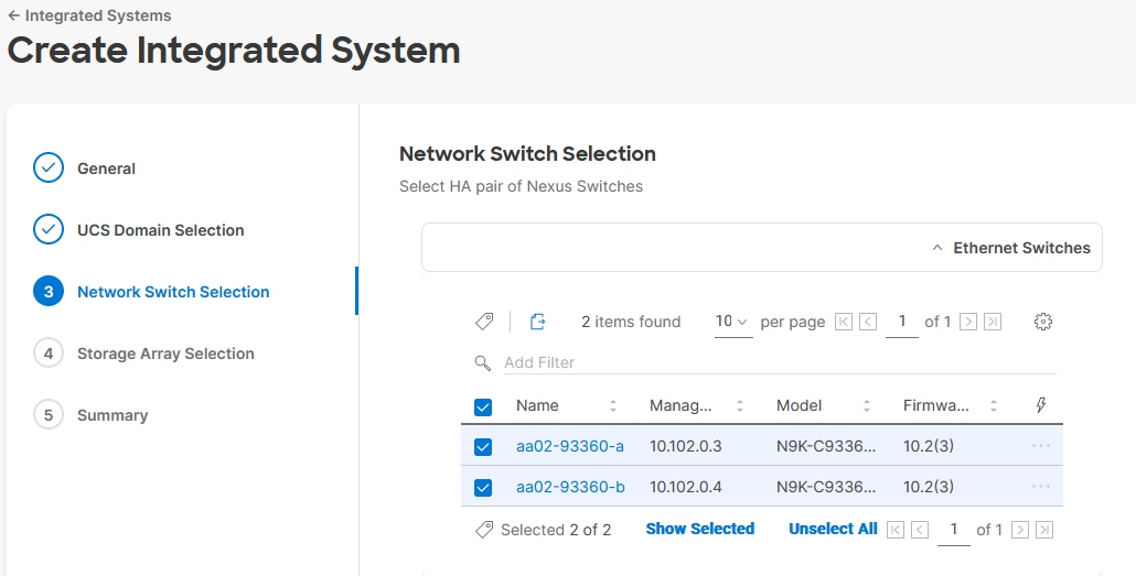
Step 7. Select all NetApp storage used in this FlexPod and click Next.
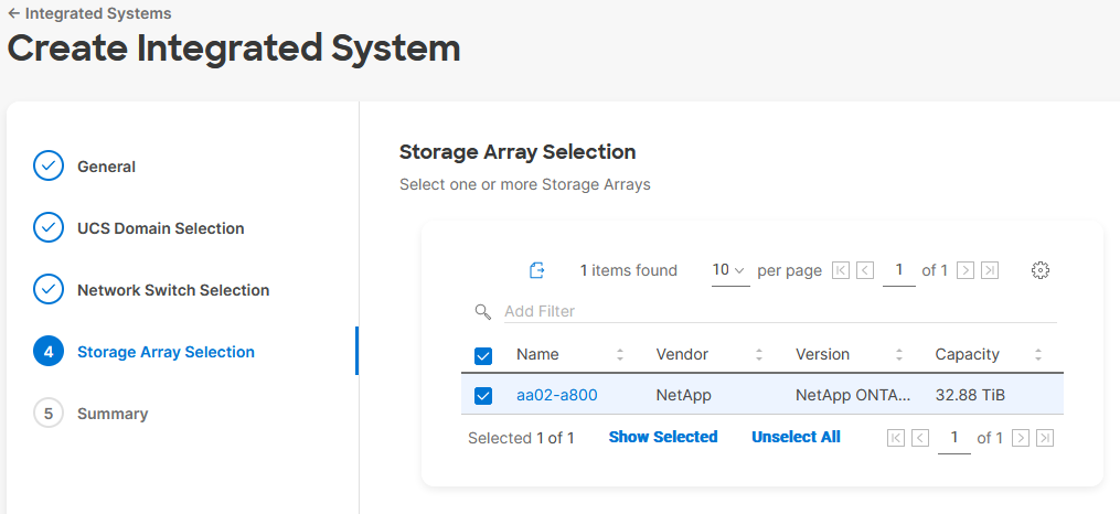
Step 8. Look over the Summary information and click Create. After a few minutes, the FlexPod Integrated System will appear under Integrated Systems.
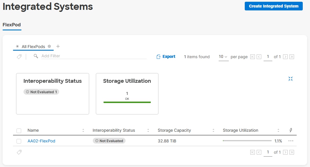
Note: You can click the “…” to the right of the FlexPod name and run an Interoperability check on the FlexPod. This check will take information on the FlexPod already checked against the Cisco UCS Hardware Compatibility List (HCL) and also check this information against the NetApp Interoperability Matrix Tool (IMT).
Step 9. Click on the FlexPod name to see detailed General, Inventory, and Interoperability data on the FlexPod XCS Integrated System.
Step 10. Select My Dashboard > FlexPod to see several informational widgets on FlexPod Integrated Systems.
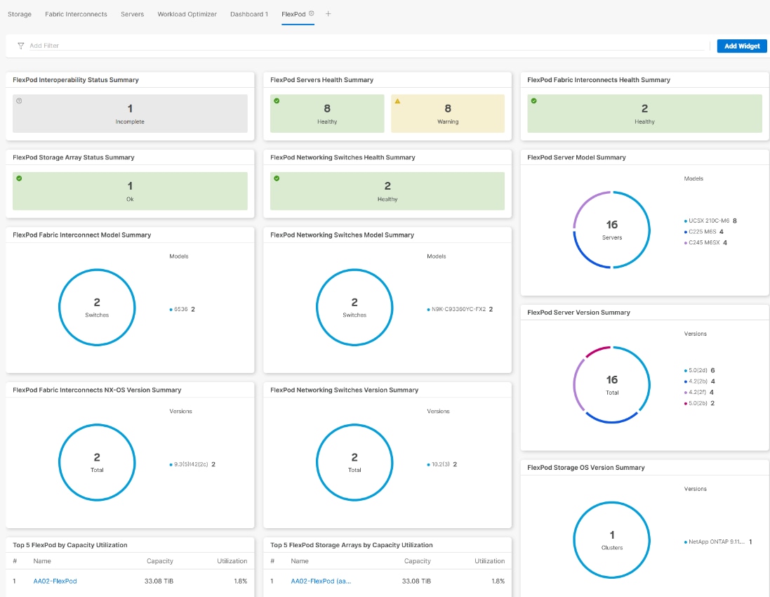
Cisco Data Center Network Manager (DCNM)–SAN
If you have fibre-channel SAN in your FlexPod, Cisco DCNM-SAN can be used to monitor, configure, and analyze Cisco fibre channel fabrics. Cisco DCNM-SAN is deployed as a virtual appliance from an OVA and is managed through a web browser. SAN Analytics can be added to provide insights into your fabric by allowing you to monitor, analyze, identify, and troubleshoot performance issues.
Prerequisites
Procedure 1. Configure prerequisites
Step 1. Licensing. Cisco DCNM-SAN includes a 60-day server-based trial license that can be used to monitor and configure Cisco MDS Fibre Channel switches and monitor Cisco Nexus switches. Both DCNM server-based and switch-based licenses can be purchased. Additionally, SAN Insights and SAN Analytics requires an additional switch-based license on each switch. Cisco MDS 32Gbps Fibre Channel switches provide a 120-day grace period to trial SAN Analytics.
Note: If using Cisco Nexus 93180YC-FX, 93360YC-FX2, or 9336C-FX2-E for SAN switching, the Nexus switch does not support SAN Analytics.
Step 2. Passwords. Cisco DCNM-SAN passwords should adhere to the following password requirements:
● It must be at least eight characters long and contain at least one alphabet and one numeral.
● It can contain a combination of alphabets, numerals, and special characters.
● Do not use any of these special characters in the DCNM password for all platforms: <SPACE> " & $ % ' ^ = < > ; : ` \ | / , .*
Step 3. DCNM SNMPv3 user on switches. Each switch (both Cisco MDS and Nexus) needs an SNMPv3 user added for DCNM to use to query and configure the switch. On each switch, enter the following command in configure terminal mode (in the example, the userid is snmpuser):
snmp-server user snmpadmin network-admin auth sha <password> priv aes-128 <privacy-password>
Step 4. On Cisco MDS switches, type show run. If snmpadmin passphrase lifetime 0 is present, enter username snm-padmin passphrase lifetime 99999 warntime 14 gracetime 3.
Note: It is important to use auth type sha and privacy auth aes-128 for both the switch and UCS snmpadmin users.
Step 5. Type “copy run start” on all switches to save the running configuration to the startup configuration.
Step 6. An SNMP Policy was added to the UCS Domain Profile in IMM to create the snmpadmin user there.
Procedure 2. Deploy the Cisco DCNM-SAN OVA
Step 1. Download the Cisco DCNM 11.5(4). Open Virtual Appliance for VMware from https://software.cisco.com/download/home/281722751/type/282088134/release/11.5(4). Extract dcnm-va.11.5.4.ova from the ZIP file.
Step 2. In the VMware vCenter HTML5 interface, select Inventory > Hosts and Clusters.
Step 3. Right-click the FlexPod-Management cluster and select Deploy OVF Template.
Step 4. Select Local file then click UPLOAD FILES. Navigate to select dcnm-va.11.5.4.ova and click Open. Click NEXT.
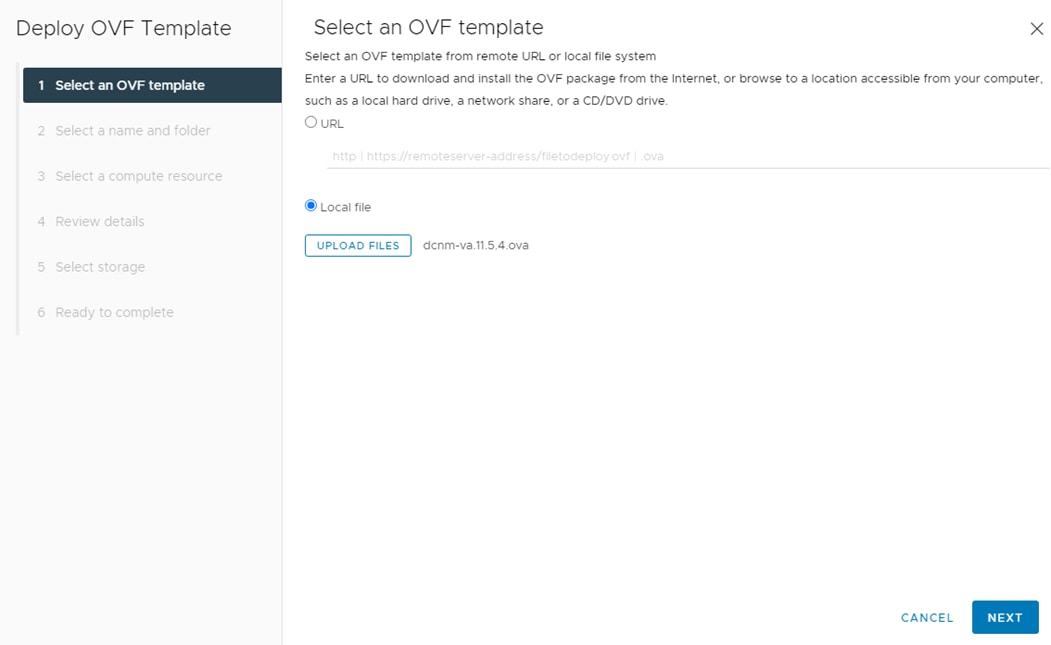
Step 5. Name the virtual machine and select the FlexPod-DC datacenter. Click NEXT.
Step 6. Select the FlexPod-Management cluster and click NEXT.
Step 7. Review the details and click NEXT.
Step 8. Scroll through and accept the license agreements. Click NEXT.
Step 9. Select the appropriate deployment configuration size and click NEXT.
Note: If using the SAN Insights and SAN Analytics feature, it is recommended to use the Huge size.
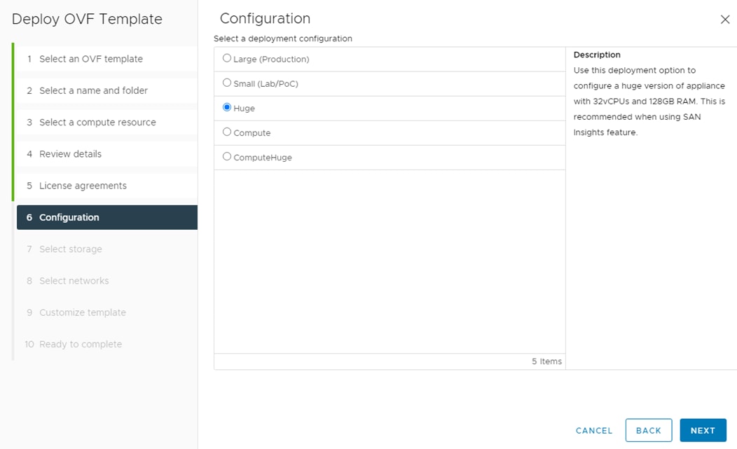
Step 10. Select infra_datastore and the Thin Provision virtual disk format. Click NEXT.
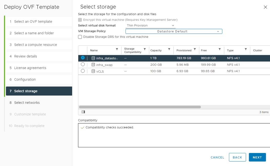
Step 11. Select IB-MGMT Network for the first and third Source Networks. Select OOB-MGMT Network for the second enhanced-fabric-mgmt Source Network. Click NEXT.
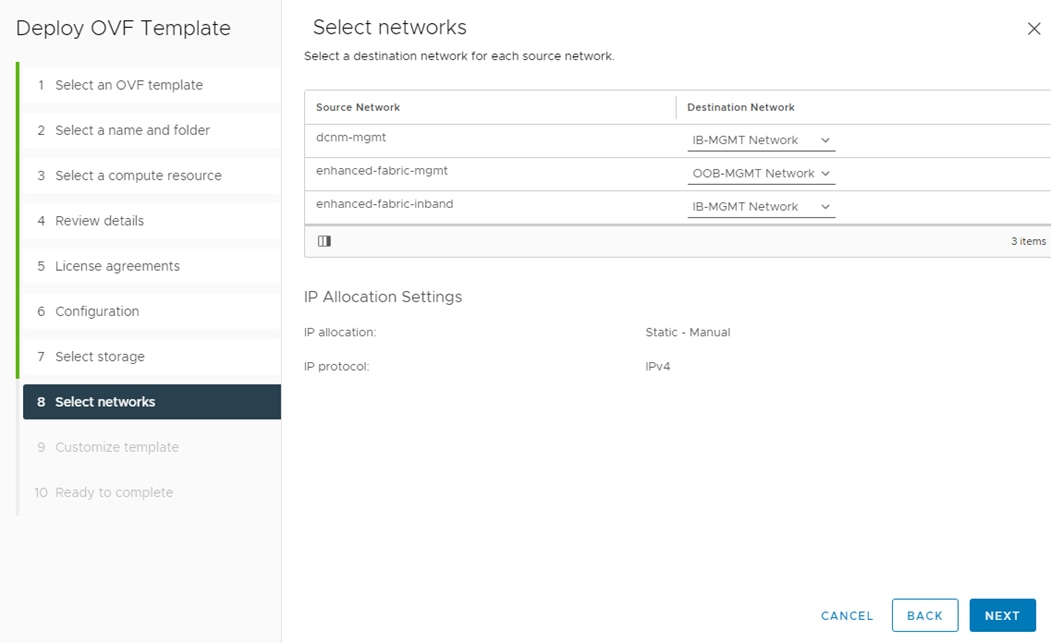
Step 12. Fill in the management IP address, subnet mask, and gateway. Set the Extra Disk Size according to how many Cisco MDS switches you will be monitoring with this DCNM. If you are only monitoring the two Cisco MDS switches in this FlexPod deployment, set this field to 32. Click NEXT.
Step 13. Review the settings and click FINISH to deploy the OVA.
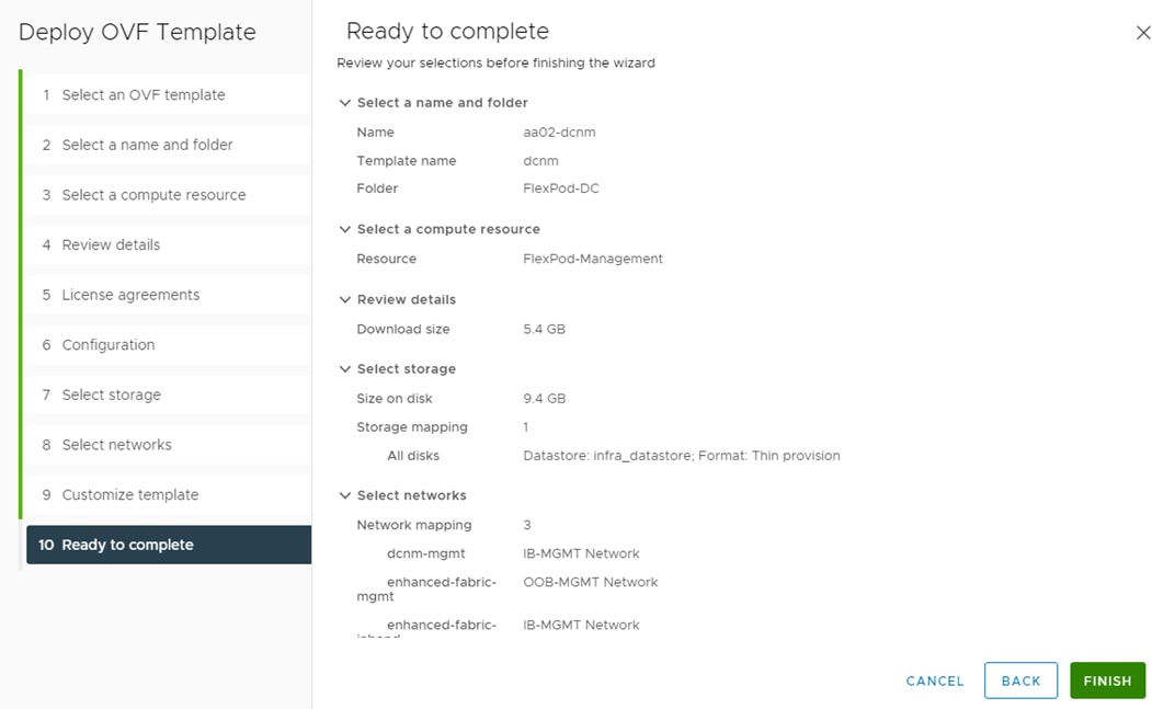
Step 14. After deployment is complete, right-click the newly deployed DCNM VM and click Edit Settings. Expand CPU and adjust the Cores per Socket setting until the number of Sockets is set to match the number of CPUs in the UCS servers used in this deployment. The following example shows 2 sockets. Click OK.
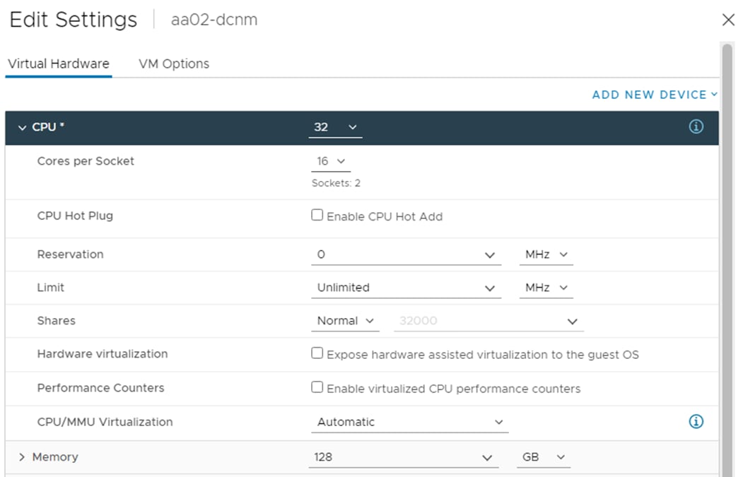
Step 15. Right-click the newly deployed DCNM VM and click Open Remote Console. Once the console is up, click the green arrow to power on the VM. Once the VM has powered up, point a web browser to the URL displayed on the console.
Step 16. Navigate the security prompts and click Get started.
Step 17. Make sure Fresh installation – Standalone is selected and click Continue.
Step 18. Select SAN only for the Installation mode and leave Cisco Systems, Inc. for the OEM vendor and click Next.
Step 19. Enter and repeat the administrator, database, and root passwords and click Next.
Step 20. Enter the DCNM FQDN, a comma-separated list of DNS servers, a comma-separated list of NTP servers, and select the appropriate time zone. Click Next.
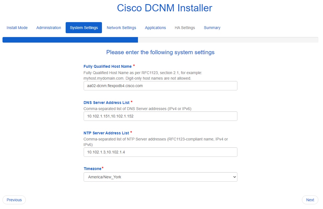
Step 21. The Management Network settings should be filled in. For Out-of-Band Network, enter an IP address in the Out-of-Band management subnet. For the Out-of-Band Network, only input the IPV4 address with prefix. Do not put in the Gateway IPv4 Address. Do not enter any information for the In-Band Network. Scroll down and click Next.
Step 22. If necessary, enter data for the Device connector configuration. Leave Internal Application Services Network set at the default setting and click Next.
Step 23. Review the Summary details and click Start installation.
Step 24. When the Installation status is complete, click Continue.
Step 25. In the vCenter HTML5 client under Hosts and Clusters, select the DCNM VM and click the Summary tab. If an alert is present that states “A newer version of VMware Tools is available for this virtual machine.,” click Upgrade VMware Tools. Select Automatic Upgrade and click UPGRADE. Wait for the VMware Tools upgrade to complete.
Procedure 3. Configure DCNM-SAN
Step 1. When the DCNM installation is complete, the browser should redirect to the DCNM management URL.
Step 2. Log in as admin with the password previously entered.
Step 3. On the message that appears, select Do not show this message again and click No.
Step 4. If you have purchased DCNM server-based or switch-based licenses, follow the instructions that came with the licenses to install them. A new DCNM installation also has a 60-day trial license.
Step 5. In the menu on the left, click Inventory > Discovery > LAN Switches.
Step 6. Click ![]() to add LAN switches. In the Add LAN Devices window, enter the mgmt0 IP address of the Nexus switch A in the Seed Switch box. Enter the snmpadmin user name and password set up in the Prerequisites section above. Set Auth-Privacy to SHA_AES. Click Next.
to add LAN switches. In the Add LAN Devices window, enter the mgmt0 IP address of the Nexus switch A in the Seed Switch box. Enter the snmpadmin user name and password set up in the Prerequisites section above. Set Auth-Privacy to SHA_AES. Click Next.
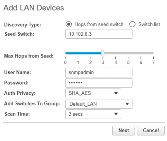
Step 7. LAN switch discovery will take a few minutes. In the LAN Discovery list that appears, the two Nexus switches and two Fabric Interconnects that are part of this FlexPod should appear with a status of “manageable.” Using the checkboxes on the left, select the two Nexus switches and two Fabric Interconnects that are part of this FlexPod. Click Add.
Step 8. After a few minutes, click the Refresh icon in the upper right-hand corner, and detailed information abut the two Nexus switches and two Fabric Interconnects that are part of this FlexPod will display.
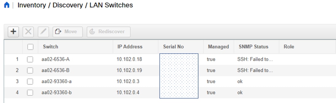
Step 9. In the menu on the left, click Inventory > Discovery > SAN Switches.
Step 10. Click ![]() to add a switching fabric.
to add a switching fabric.
Step 11. Enter either the IP address or hostname of the first Cisco MDS 9132T switch. Leave Use SNMPv3/SSH selected. Set Auth-Privacy to SHA_AES. Enter the snmpadmin user name and password set up in the Prerequisites section. Click Options>>. Enter the UCS admin user name and password. Click Add.
Note: If Cisco Nexus 93180YC-FX, 93360YC-FX2, or 9336C-FX2-E switches are being used for SAN switching, substitute them for MDS 9132Ts. They will need to be added again under SAN switches since LAN and SAN switching are handled separately in DCNM.
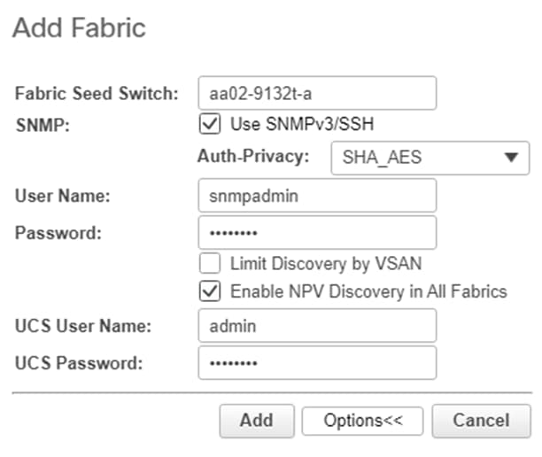
Step 12. Repeat steps 9-11 to add the second Cisco MDS 9132T and Fabric Interconnect.
The two SAN fabrics should now appear in the Inventory.
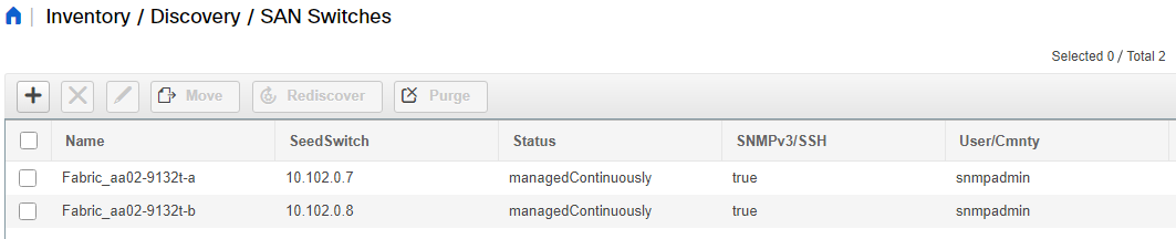
Step 13. Select Inventory > Discovery > Virtual Machine Manager.
Step 14. Click ![]() to add the vCenter.
to add the vCenter.
Step 15. In the Add VCenter window, enter the IP address of the vCenter VCSA. Enter the administrator@vsphere.local user name and password. Click Add. The vCenter should now appear in the inventory.
Step 16. Select Inventory > Switches. All LAN and SAN switches should now appear in the inventory.
Step 17. Select Administration > Performance Setup > LAN Collections.
Step 18. Select the Default_LAN group and all information you would like to collect. Click Apply. Click Yes to restart the Performance Collector.
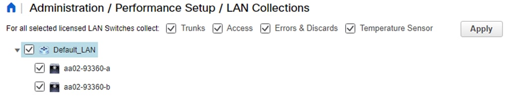
Step 19. Select Administration > Performance Setup > SAN Collections.
Step 20. Select both fabrics. Select all information you would like to collect and click Apply. Click Yes to restart the Performance Collector.
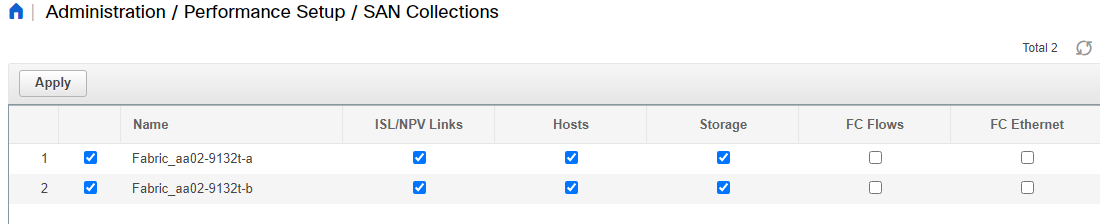
Step 21. Select Configure > SAN > Device Alias. Since device-alias mode enhanced was configured in the Cisco MDS 9132T switches, Device Aliases can be created and deleted from DCNM and pushed to the MDS switches.
Step 22. Select Configure > SAN > Zoning. Just as Device Aliases can be created and deleted from DCNM, zones can be created, deleted, and modified in DCNM and pushed to the MDS switches. Make sure to enable Smart Zoning and to Zone by Device Alias.
You can now explore all of the different options and information provided by DCNM SAN. See Cisco DCNM SAN Management for OVA and ISO Deployments Configuration Guide, Release 11.5(x).
Configure SAN Insights in DCNM SAN
The SAN Insights feature enables you to configure, monitor, and view the flow analytics in fabrics. Cisco DCNM enables you to visually see health-related indicators in the interface so that you can quickly identify issues in fabrics. Also, the health indicators enable you to understand the problems in fabrics. The SAN Insights feature also pro-vides more comprehensive end-to-end flow-based data from host to LUN.
● Ensure that the time configurations set above, including daylight savings settings are consistent across the MDS switches and Cisco DCNM.
● SAN Insights requires installation of a SMART SAN Analytics license on each switch. To trial the feature, each switch includes a one-time 120-day grace period for SAN Analytics from the time the feature is first enabled.
● SAN Insights supports current Fibre Channel Protocol (SCSI) and NVMe over Fibre Channel (NVMe).
● SAN Insights works by enabling SAN Analytics and Telemetry Streaming on each switch. The switches then stream the SAN Analytics data to DCNM, which collects, correlates, and displays statistics. All configurations can be done from DCNM.
● Only Cisco MDS switches support SAN Analytics. Cisco Nexus switches do not support SAN Analytics.
● For more information on SAN Insights, see the Cisco DCNM SAN Management for OVA and ISO Deployments Configuration Guide, Release 11.5(x).
● For more information on SAN Analytics, see https://www.cisco.com/c/en/us/td/docs/dcn/mds9000/sw/9x/configuration/san-analytics/cisco-mds-9000-san-analytics-telemetry-streaming-configuration-guide-9x.html.
Procedure 1. Configure SAN Insights in DCNM SAN
Step 1. Click Configure > SAN > SAN Insights. Click Continue.
Step 2. Select Fabric A. Click Continue.
Step 3. Select the Fabric A Cisco MDS switch. Under Install Query click None and from the drop-down list click Storage. Under Subscriptions, select SCSI & NVMe or whatever you have currently installed. Optionally, under Receiver, select the IP address in the Out-of-Band Management subnet configured for DCNM. Click Save, then click Continue.
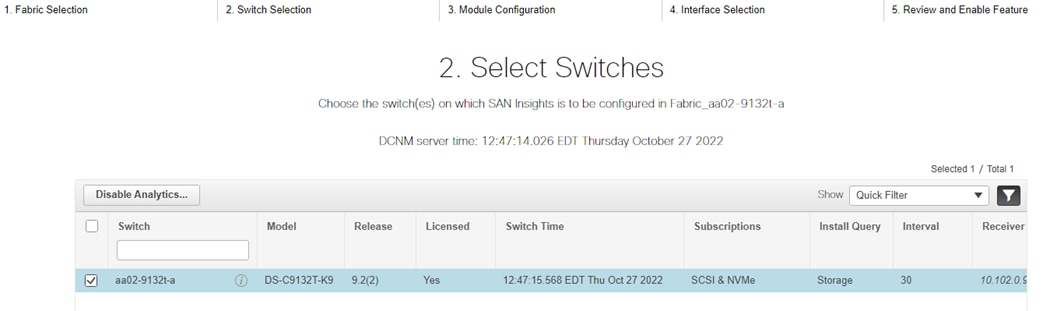
Step 4. Review the information and click Continue.
Step 5. Expand the switch and then the module. Under Enable / Disable SCSI Telemetry, click the left icon to enable telemetry on the ports connected to the NetApp AFF A800. Under Enable / Disable NVMe Telemetry, click the left icon to enable telemetry on the ports connected to the NetApp AFF A800. Click Continue.
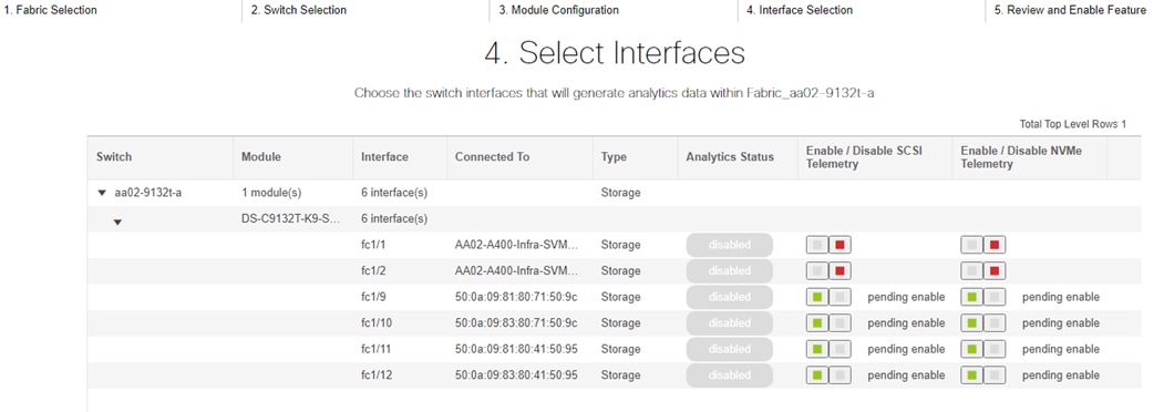
Step 6. Review the information and click Commit to push the configuration to the Cisco MDS switch.
Step 7. Ensure that the two operations were successful and click Close.
Step 8. Repeat steps 1 - 7 to install SAN Analytics and Telemetry on the Fabric B switch.
Note: After approximately two hours, you can view SAN Analytics data under the Dashboard and Monitor.
John George, Technical Marketing Engineer, Cisco Systems, Inc.
John has been involved in designing, developing, validating, and supporting the FlexPod Converged Infrastructure since it was developed almost 12 years ago. Before his roles with FlexPod, he supported and administered a large worldwide training network and VPN infrastructure. John holds a master’s degree in Computer Engineering from Clemson University.
Roney Daniel, Technical Marketing Engineer, Hybrid Cloud Infra & OEM Solutions, NetApp Inc.
Roney Daniel is a Technical Marketing engineer at NetApp. He has over 25 years of experience in the networking industry. Prior to NetApp, Roney worked at Cisco Systems in various roles with Cisco TAC, Financial Test Lab, Systems and solution engineering BUs and Cisco IT. He has a bachelor's degree in Electronics and Communication engineering and is a data center Cisco Certified Internetwork Expert (CCIE 42731).
Kamini Singh, Technical Marketing Engineer, Hybrid Cloud Infra & OEM Solutions, NetApp
Kamini Singh is a Technical Marketing engineer at NetApp. She has three years of experience in data center infrastructure solutions. Kamini focuses on FlexPod hybrid cloud infrastructure solution design, implementation, validation, automation, and sales enablement. Kamini holds a bachelor’s degree in Electronics and Communication and a master’s degree in Communication Systems.
Acknowledgements
For their support and contribution to the design, validation, and creation of this Cisco Validated Design, the authors would like to thank:
● Haseeb Niazi, Principal Technical Marketing Engineer, Cisco Systems, Inc.
● Paniraja Koppa, Technical Marketing Engineer, Cisco Systems, Inc.
● Lisa DeRuyter-Wawrzynski, Information Developer, Cisco Systems, Inc.
Appendix
This appendix is organized into the following:
● FlexPod with Cisco Nexus SAN Switching Configuration – Part 1
● FlexPod with Cisco Nexus 93360YC-FX2 SAN Switching Configuration – Part 2
● Create a FlexPod ESXi Custom ISO using VMware vCenter
● Active IQ Unified Manager User Configuration
● Active IQ Unified Manager vCenter Configuration
Note: The features and functionality explained in this Appendix are optional configurations which can be helpful in configuring and managing the FlexPod deployment.
FlexPod with Cisco Nexus SAN Switching Configuration – Part 1
When using the Cisco Nexus switches for SAN switching, the following alternate base switch setup should be used. This configuration uses 100G FCoE uplinks from the Cisco UCS fabric interconnects to the Cisco Nexus switches. 25G uplinks can also be used. Figure 6 shows the validation lab cabling for this setup.
Figure 5. Cisco Nexus SAN Switching Cabling with FCoE Fabric Interconnect Uplinks
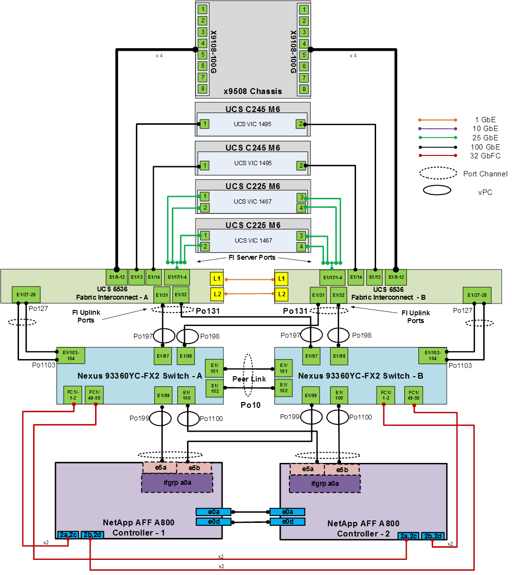
FlexPod Cisco Nexus 93180YC-FX SAN Switching Base Configuration
The following procedures describe how to configure the Cisco Nexus 93180YC-FX switches for use in a base FlexPod environment that uses the switches for both LAN and SAN switching. This procedure assumes you’re using Cisco Nexus 9000 10.2(3)F. This procedure also assumes that you have created an FCoE Uplink Port Channel on the appropriate ports in the Cisco UCS IMM Port Policies for each Cisco UCS fabric interconnect.
Procedure 1. Set Up Initial Configuration in Cisco Nexus 93360YC-FX2 A
Step 1. Configure the switch:
Note: On initial boot and connection to the serial or console port of the switch, the NX-OS setup should automatically start and attempt to enter Power on Auto Provisioning.
Abort Power On Auto Provisioning [yes - continue with normal setup, skip - bypass password and basic configuration, no - continue with Power On Auto Provisioning] (yes/skip/no)[no]: yes
Disabling POAP.......Disabling POAP
poap: Rolling back, please wait... (This may take 5-15 minutes)
---- System Admin Account Setup ----
Do you want to enforce secure password standard (yes/no) [y]: Enter
Enter the password for "admin": <password>
Confirm the password for "admin": <password>
Would you like to enter the basic configuration dialog (yes/no): yes
Create another login account (yes/no) [n]: Enter
Configure read-only SNMP community string (yes/no) [n]: Enter
Configure read-write SNMP community string (yes/no) [n]: Enter
Enter the switch name: <nexus-A-hostname>
Continue with Out-of-band (mgmt0) management configuration? (yes/no) [y]: Enter
Mgmt0 IPv4 address: <nexus-A-mgmt0-ip>
Mgmt0 IPv4 netmask: <nexus-A-mgmt0-netmask>
Configure the default gateway? (yes/no) [y]: Enter
IPv4 address of the default gateway: <nexus-A-mgmt0-gw>
Configure advanced IP options? (yes/no) [n]: Enter
Enable the telnet service? (yes/no) [n]: Enter
Enable the ssh service? (yes/no) [y]: Enter
Type of ssh key you would like to generate (dsa/rsa) [rsa]: Enter
Number of rsa key bits <1024-2048> [1024]: Enter
Configure the ntp server? (yes/no) [n]: Enter
Configure default interface layer (L3/L2) [L2]: Enter
Configure default switchport interface state (shut/noshut) [noshut]: shut
Enter basic FC configurations (yes/no) [n]: y
Configure default physical FC switchport interface state (shut/noshut) [shut]: Enter
Configure default switchport trunk mode (on/off/auto) [on]: auto
Configure default zone policy (permit/deny) [deny]: Enter
Enable full zoneset distribution? (yes/no) [n]: y
Configure CoPP system profile (strict/moderate/lenient/dense) [strict]: Enter
Would you like to edit the configuration? (yes/no) [n]: Enter
Step 2. Review the configuration summary before enabling the configuration:
Use this configuration and save it? (yes/no) [y]: Enter
Procedure 2. Set Up Initial Configuration in Cisco Nexus 93360YC-FX2 B
Step 1. Configure the switch:
Note: On initial boot and connection to the serial or console port of the switch, the NX-OS setup should automatically start and attempt to enter Power on Auto Provisioning.
Abort Power On Auto Provisioning [yes - continue with normal setup, skip - bypass password and basic configuration, no - continue with Power On Auto Provisioning] (yes/skip/no)[no]: yes
Disabling POAP.......Disabling POAP
poap: Rolling back, please wait... (This may take 5-15 minutes)
---- System Admin Account Setup ----
Do you want to enforce secure password standard (yes/no) [y]: Enter
Enter the password for "admin": <password>
Confirm the password for "admin": <password>
Would you like to enter the basic configuration dialog (yes/no): yes
Create another login account (yes/no) [n]: Enter
Configure read-only SNMP community string (yes/no) [n]: Enter
Configure read-write SNMP community string (yes/no) [n]: Enter
Enter the switch name: <nexus-B-hostname>
Continue with Out-of-band (mgmt0) management configuration? (yes/no) [y]: Enter
Mgmt0 IPv4 address: <nexus-B-mgmt0-ip>
Mgmt0 IPv4 netmask: <nexus-B-mgmt0-netmask>
Configure the default gateway? (yes/no) [y]: Enter
IPv4 address of the default gateway: <nexus-B-mgmt0-gw>
Configure advanced IP options? (yes/no) [n]: Enter
Enable the telnet service? (yes/no) [n]: Enter
Enable the ssh service? (yes/no) [y]: Enter
Type of ssh key you would like to generate (dsa/rsa) [rsa]: Enter
Number of rsa key bits <1024-2048> [1024]: Enter
Configure the ntp server? (yes/no) [n]: Enter
Configure default interface layer (L3/L2) [L2]: Enter
Configure default switchport interface state (shut/noshut) [noshut]: shut
Enter basic FC configurations (yes/no) [n]: y
Configure default physical FC switchport interface state (shut/noshut) [shut]: Enter
Configure default switchport trunk mode (on/off/auto) [on]: auto
Configure default zone policy (permit/deny) [deny]: Enter
Enable full zoneset distribution? (yes/no) [n]: y
Configure CoPP system profile (strict/moderate/lenient/dense) [strict]: Enter
Would you like to edit the configuration? (yes/no) [n]: Enter
Step 2. Review the configuration summary before enabling the configuration:
Use this configuration and save it? (yes/no) [y]: Enter
Note: SAN switching requires both the SAN_ENTERPRISE_PKG and FC_PORT_ACTIVATION_PKG licenses. Ensure these licenses are installed on each Cisco Nexus switch.
Note: This section is structured as a green field switch setup. If existing switches that are switching active traffic are being setup, execute this procedure down through Perform TCAM Carving and Configure Unified Ports in Cisco Nexus 93360YC-FX2 A and B first on one switch and then when that is completed, execute on the other switch.
Procedure 3. Install feature-set fcoe in Cisco Nexus 93360YC-FX2 A and B
Step 1. Run the following commands to set global configurations:
config t
install feature-set fcoe
feature-set fcoe
system default switchport trunk mode auto
system default switchport mode F
Note: These steps are provided in case the basic FC configurations were not configured in the switch setup script de-tailed in the previous section.
Procedure 4. Set System-Wide QoS Configurations in Cisco Nexus 93360YC-FX2 A and B
Step 1. Run the following commands to set global configurations:
config t
system qos
service-policy type queuing input default-fcoe-in-que-policy
service-policy type queuing output default-fcoe-8q-out-policy
service-policy type network-qos default-fcoe-8q-nq-policy
copy run start
Procedure 5. Perform TCAM Carving and Configure Unified Ports (UP) in Cisco Nexus 93360YC-FX2 A and B
Note: SAN switching requires TCAM carving for lossless fibre channel no-drop support. Also, unified ports need to be converted to fc ports.
Note: On the Cisco Nexus 93360YC-FX2, UP ports are converted to FC in groups of 4 in columns, for example, 1,2,49,50.
Step 1. Run the following commands:
hardware access-list tcam region ing-racl 1536
hardware access-list tcam region ing-ifacl 256
hardware access-list tcam region ing-redirect 256
slot 1
port 1,2,49,50,3,4,51,52 type fc
copy running-config startup-config
reload
This command will reboot the system. (y/n)? [n] y
Step 2. After the switch reboots, log back in as admin. Run the following commands:
show hardware access-list tcam region |i i ing-racl
show hardware access-list tcam region |i i ing-ifacl
show hardware access-list tcam region |i i ing-redirect
show int status
FlexPod Cisco Nexus 93360YC-FX2 SAN Switching Ethernet Switching Manual Configuration
For the manual configuration of the ethernet part of the Cisco Nexus 93360YC-FX2 switches when using the switches for SAN switching, once the base configuration above is set, return to FlexPod Cisco Nexus Switch Manual Configuration, and execute from there.
FlexPod with Cisco Nexus 93360YC-FX2 SAN Switching Configuration – Part 2
Note: If the Cisco Nexus 93360YC-FX2 switch is being used for SAN Switching, this section should be completed in place of the Cisco MDS section of this document.
FlexPod Cisco Nexus 93360YC-FX2 SAN Switching Ethernet Switching Manual Configuration
This section details the manual configuration of the SAN part of the Cisco Nexus 93360YC-FX2 switches when using the switches for SAN switching.
Procedure 1. Enable Features in Cisco Nexus 93360YC-FX2 A and B
Step 1. Log in as admin.
Note: SAN switching requires both the SAN_ENTERPRISE_PKG and FC_PORT_ACTIVATION_PKG licenses. Make sure these licenses are installed on each Cisco Nexus 93360YC-FX2 switch.
Step 2. Because basic FC configurations were entered in the setup script, feature-set fcoe has been automatically in-stalled and enabled. Run the following commands:
config t
feature npiv
feature fport-channel-trunk
system default switchport trunk mode auto
system default switchport mode F
Procedure 2. Configure FCoE VLAN and Fibre Channel Ports in Cisco Nexus 93360YC-FX2 A
Step 1. From the global configuration mode, run the following commands:
vlan <vsan-a-id>
fcoe vsan <vsan-a-id>
name FCoE-VLAN-A
interface fc1/1
switchport description <st-clustername>-01:2a
port-license acquire
switchport speed 32000
switchport trunk mode off
no shutdown
exit
interface fc1/2
switchport description <st-clustername>-01:2c
port-license acquire
switchport speed 32000
switchport trunk mode off
no shutdown
exit
interface fc1/49
switchport description <st-clustername>-02:2a
port-license acquire
switchport speed 32000
switchport trunk mode off
no shutdown
exit
interface fc1/50
switchport description <st-clustername>-02:2c
port-license acquire
switchport speed 32000
switchport trunk mode off
no shutdown
exit
interface Eth1/103
description <ucs-domainname>-a:FCoE:1/27
udld enable
channel-group 1103 mode active
no shutdown
exit
interface Eth1/104
description <ucs-domainname>-a:FCoE:1/28
udld enable
channel-group 1103 mode active
no shutdown
exit
interface port-channel1103
description <ucs-domainname>-a:FCoE
switchport mode trunk
switchport trunk allowed vlan <vsan-a-id>
spanning-tree port type edge trunk
mtu 9216
no negotiate auto
service-policy type qos input default-fcoe-in-policy
no shutdown
exit
interface vfc1103
switchport description <ucs-domainname>-a:FCoE
bind interface port-channel1103
switchport trunk allowed vsan <vsan-a-id>
switchport trunk mode on
no shutdown
exit
Procedure 3. Configure FCoE VLAN and Fibre Channel Ports in Cisco Nexus 93360YC-FX2 B
Step 1. From the global configuration mode, run the following commands:
vlan <vsan-b-id>
fcoe vsan <vsan-b-id>
name FCoE-VLAN-B
interface fc1/1
switchport description <st-clustername>-01:2b
port-license acquire
switchport speed 32000
switchport trunk mode off
no shutdown
exit
interface fc1/2
switchport description <st-clustername>-01:2d
port-license acquire
switchport speed 32000
switchport trunk mode off
no shutdown
exit
interface fc1/49
switchport description <st-clustername>-02:2b
port-license acquire
switchport speed 32000
switchport trunk mode off
no shutdown
exit
interface fc1/50
switchport description <st-clustername>-02:2d
port-license acquire
switchport speed 32000
switchport trunk mode off
no shutdown
exit
interface Eth1/103
description <ucs-domainname>-b:FCoE:1/27
udld enable
channel-group 1103 mode active
no shutdown
exit
interface Eth1/104
description <ucs-domainname>-b:FCoE:1/28
udld enable
channel-group 1103 mode active
no shutdown
exit
interface port-channel1103
description <ucs-domainname>-b:FCoE
switchport mode trunk
switchport trunk allowed vlan <vsan-b-id>
spanning-tree port type edge trunk
mtu 9216
service-policy type qos input default-fcoe-in-policy
no shutdown
exit
interface vfc1103
switchport description <ucs-domainname>-b:FCoE
bind interface port-channel1103
switchport trunk allowed vsan <vsan-b-id>
switchport trunk mode on
no shutdown
Procedure 4. Create VSANs and add Ports in Cisco Nexus 93360YC-FX2 A
Step 1. From the global configuration mode, run the following commands:
vsan database
vsan <vsan-a-id>
vsan <vsan-a-id> name Fabric-A
vsan <vsan-a-id> interface fc1/1
Traffic on fc1/1 may be impacted. Do you want to continue? (y/n) [n] y
vsan <vsan-a-id> interface fc1/2
Traffic on fc1/2 may be impacted. Do you want to continue? (y/n) [n] y
vsan <vsan-a-id> interface fc1/49
Traffic on fc1/49 may be impacted. Do you want to continue? (y/n) [n] y
vsan <vsan-a-id> interface fc1/50
Traffic on fc1/50 may be impacted. Do you want to continue? (y/n) [n] y
vsan <vsan-a-id> interface vfc1103
exit
zone smart-zoning enable vsan <vsan-a-id>
zoneset distribute full vsan <vsan-a-id>
copy run start
Procedure 5. Create VSANs add Ports in Cisco Nexus 93360YC-FX2 B
Step 1. From the global configuration mode, run the following commands:
vsan database
vsan <vsan-b-id>
vsan <vsan-b-id> name Fabric-B
vsan <vsan-b-id> interface fc1/1
Traffic on fc1/1 may be impacted. Do you want to continue? (y/n) [n] y
vsan <vsan-b-id> interface fc1/2
Traffic on fc1/2 may be impacted. Do you want to continue? (y/n) [n] y
vsan <vsan-b-id> interface fc1/49
Traffic on fc1/49 may be impacted. Do you want to continue? (y/n) [n] y
vsan <vsan-b-id> interface fc1/50
Traffic on fc1/50 may be impacted. Do you want to continue? (y/n) [n] y
vsan <vsan-b-id> interface vfc1103
exit
zone smart-zoning enable vsan <vsan-b-id>
zoneset distribute full vsan <vsan-b-id>
copy run start
Procedure 6. Create Device Aliases in Cisco Nexus 93360YC-FX A to create Zones
Step 1. The WWPN information required to create device-alias and zones can be gathered from NetApp using the following command:
network interface show -vserver Infra-SVM -data-protocol fcp
network interface show -vserver <svm-name> -data-protocol fc-nvme
Step 2. The WWPN information for a Server Profile can be obtained by logging into Intersight, go Cisco Intersight and select each of the 3 server service profiles by going to Infrastructure Service > Configure > Profiles > UCS Server Profiles > <Desired Server Profile> > Inventory > Network Adapters > <Adapter> > Interfaces. The needed WWPNs can be found under HBA Interfaces.
Step 3. Login as admin and from the global configuration mode, run the following commands:
config t
device-alias mode enhanced
device-alias database
device-alias name <svm-name>-fcp-lif-01a pwwn <fcp-lif-01a-wwpn>
device-alias name <svm-name>-fcp-lif-02a pwwn <fcp-lif-02a-wwpn>
device-alias name FCP-<server1-hostname>-A pwwn <fcp-server1-wwpna>
device-alias name FCP-<server2-hostname>-A pwwn <fcp-server2-wwpna>
device-alias name FCP-<server3-hostname>-A pwwn <fcp-server3-wwpna>
device-alias name <svm-name>-fc-nvme-lif-01a pwwn <fc-nvme-lif-01a-wwpn>
device-alias name <svm-name>-fc-nvme-lif-02a pwwn <fc-nvme-lif-02a-wwpn>
device-alias name FC-NVMe-<server1-hostname>-A pwwn <fc-nvme-server1-wwpna>
device-alias name FC-NVMe-<server2-hostname>-A pwwn <fc-nvme-server2-wwpna>
device-alias name FC-NVMe-<server3-hostname>-A pwwn <fc-nvme-server3-wwpna>
device-alias commit
show device-alias database
Procedure 7. Create Device Aliases in Cisco Nexus 93360YC-FX2 B to create Zones
Step 1. Login as admin and from the global configuration mode, run the following commands:
config t
device-alias mode enhanced
device-alias database
device-alias name <svm-name>-fcp-lif-01b pwwn <fcp-lif-01b-wwpn>
device-alias name <svm-name>-fcp-lif-02b pwwn <fcp-lif-02b-wwpn>
device-alias name FCP-<server1-hostname>-B pwwn <fcp-server1-wwpnb>
device-alias name FCP-<server2-hostname>-B pwwn <fcp-server2-wwpnb>
device-alias name FCP-<server3-hostname>-B pwwn <fcp-server3-wwpnb>
device-alias name <svm-name>-fc-nvme-lif-01b pwwn <fc-nvme-lif-01b-wwpn>
device-alias name <svm-name>-fc-nvme-lif-02b pwwn <fc-nvme-lif-02b-wwpn>
device-alias name FC-NVMe-<server1-hostname>-B pwwn <fc-nvme-server1-wwpnb>
device-alias name FC-NVMe-<server2-hostname>-B pwwn <fc-nvme-server2-wwpnb>
device-alias name FC-NVMe-<server3-hostname>-B pwwn <fc-nvme-server3-wwpnb>
device-alias commit
show device-alias database
Procedure 8. Create Zones and Zoneset in Cisco Nexus 93360YC-FX2 A
Step 1. Run the following commands to create the required zones and zoneset on Fabric A:
zone name FCP-<svm-name>-A vsan <vsan-a-id>
member device-alias FCP-<server1-hostname>-A init
member device-alias FCP-<server2-hostname>-A init
member device-alias FCP-<server3-hostname>-A init
member device-alias <svm-name>-fcp-lif-01a target
member device-alias <svm-name>-fcp-lif-02a target
exit
zone name FC-NVME-<svm-name>-A vsan <vsan-a-id>
member device-alias FC-NVME-<server1-hostname>-A init
member device-alias FC-NVME-<server2-hostname>-A init
member device-alias FC-NVME-<server3-hostname>-A init
member device-alias <svm-name>-fc-nvme-lif-01a target
member device-alias <svm-name>-fc-nvme-lif-02a target
exit
zoneset name FlexPod-Fabric-A vsan <vsan-a-id>
member FCP-<svm-name>-A
member FC-NVME-<svm-name>-A
exit
zoneset activate name FlexPod-Fabric-A vsan <vsan-a-id>
show zoneset active
copy r s
Procedure 9. Create Zones and Zoneset in Cisco Nexus 93360YC-FX2 B
Step 1. Run the following commands to create the required zones and zoneset on Fabric B:
zone name FCP-<svm-name>-B vsan <vsan-b-id>
member device-alias FCP-<server1-hostname>-B init
member device-alias FCP-<server2-hostname>-B init
member device-alias FCP-<server3-hostname>-B init
member device-alias <svm-name>-fcp-lif-01b target
member device-alias <svm-name>-fcp-lif-02b target
exit
zone name FC-NVME-<svm-name>-B vsan <vsan-b-id>
member device-alias FC-NVME-<server1-hostname>-B init
member device-alias FC-NVME-<server2-hostname>-B init
member device-alias FC-NVME-<server3-hostname>-B init
member device-alias <svm-name>-fc-nvme-lif-01b target
member device-alias <svm-name>-fc-nvme-lif-02b target
exit
zoneset name FlexPod-Fabric-B vsan <vsan-b-id>
member FCP-<svm-name>-B
member FC-NVME-<svm-name>-B
exit
zoneset activate name FlexPod-Fabric-B vsan <vsan-b-id>
show zoneset active
copy r s
Procedure 10. Switch Testing Commands
The following commands can be used to check for correct switch configuration:
Note: Some of these commands need to run after further configuration of the FlexPod components are complete to see complete results.
show run
show run int
show int
show int status
show int brief
show flogi database
show device-alias database
show zone
show zoneset
show zoneset active
Create a FlexPod ESXi Custom ISO using VMware vCenter
In this Cisco Validated Design (CVD), the Cisco Custom Image for ESXi 7.0 U3 Install CD was used to install VMware ESXi. After this installation, the Cisco UCS VIC fnic driver, the lsi_mr3 driver, and the NetApp NFS Plug-in for VMware VAAI had to be installed or updated during the FlexPod deployment. vCenter 7.0U3 or later can be used to produce a FlexPod custom ISO containing the updated UCS VIC fnic driver, the lsi_mr3 driver, and the NetApp NFS Plug-in for VMware VAAI. This ISO can be used to install VMware ESXi 7.0U3 without having to do any additional driver updates.
Procedure 1. Create a FlexPod ESXi Custom ISO using VMware vCenter
Step 1. Download the Cisco Custom Image for ESXi 7.0 U3 Offline Bundle. This file (VMware-ESXi-7.0.3d-19482537-Custom-Cisco-4.2.2-a-depot.zip) can be used to produce the FlexPod ESXi 7.0U3 CD ISO.
Step 2. Download the following listed .zip files:
● VMware ESXi 7.0 nfnic 5.0.0.34 Driver for Cisco VIC Adapters – Cisco-nfnic_5.0.0.34-1OEM.700.1.0.15843807_19966277.zip – extracted from the downloaded zip
● VMware ESXi 7.0 lsi_mr3 7.720.04.00-1OEM SAS Driver for Broadcom Megaraid 12Gbps - Broadcom-lsi-mr3_7.720.04.00-1OEM.700.1.0.15843807_19476191.zip – extracted from the downloaded zip
● NetApp NFS Plug-in for VMware VAAI 2.0 – NetAppNasPluginV2.0.zip
● The Cisco VIC nenic driver would also normally be downloaded and added to the FlexPod Custom ISO, but the 1.0.42.0 nenic driver is already included in the Cisco Custom ISO.
Step 3. Log into the VMware vCenter HTML5 Client as administrator@vsphere.local.
Step 4. Under the Menu at the top, select Auto Deploy.
Step 5. If you see the following, select ENABLE IMAGE BUILDER.
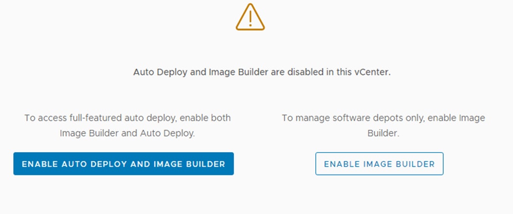
Step 6. Click IMPORT to upload a software depot.
Step 7. Name the depot “Cisco Custom ESXi 7.0U3.” Click BROWSE. Browse to the local location of the VMware-ESXi-7.0.3d-19482537-Custom-Cisco-4.2.2-a-depot.zip file downloaded above, highlight it, and click Open.
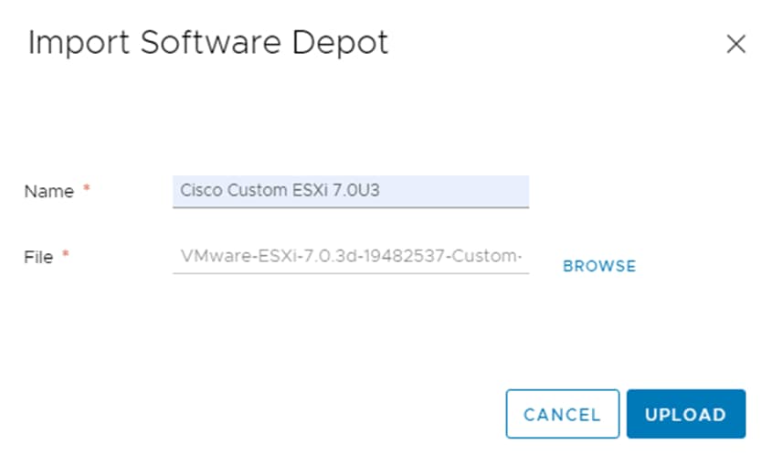
Step 8. Click UPLOAD to upload the software depot.
Step 9. Repeat steps 1 - 8 to add software depots for Cisco-nfnic_5.0.0.34-1OEM.700.1.0.15843807_19966277.zip, Broadcom-lsi-mr3_7.720.04.00-1OEM.700.1.0.15843807_19476191.zip, and NetAppNasPluginV2.0.zip.
Step 10. Click NEW to add a custom software depot.
Step 11. Select Custom depot and name the custom depot FlexPod-ESXi-7.0U3.
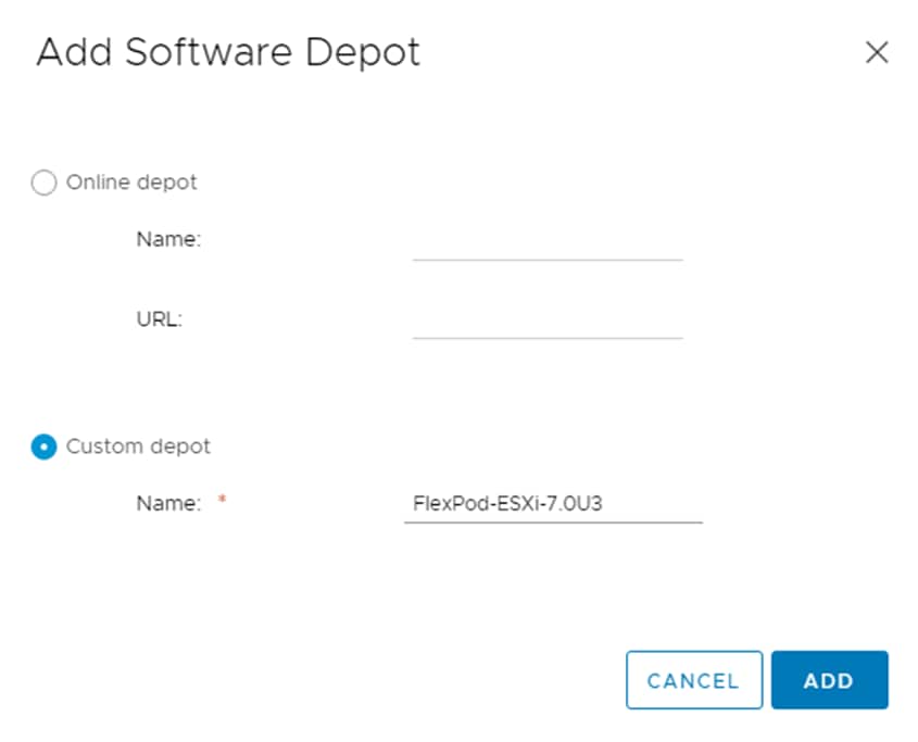
Step 12. Click ADD to add the custom software depot.
Step 13. From the drop-down list, select the Cisco Custom ESXi-7.0U3 (ZIP) software depot. Make sure the Image Profiles tab is selected and then click the radio button to select the Cisco-UCS-Addon-ESXi-7U3d-19482537_4.2.2-a image profile. Click CLONE to clone the image profile.
Step 14. Name the clone FlexPod-ESXi-7.0U3. For Vendor, enter Cisco-NetApp. For Description, enter Cisco Custom ISO ESXi 7.0U3 with Cisco VIC nfnic 5.0.0.34, LSI-MR3 7.720.04.0 and NetAppNasPluginv2.0. Select FlexPod-ESXi-7.0U3 for Software depot.
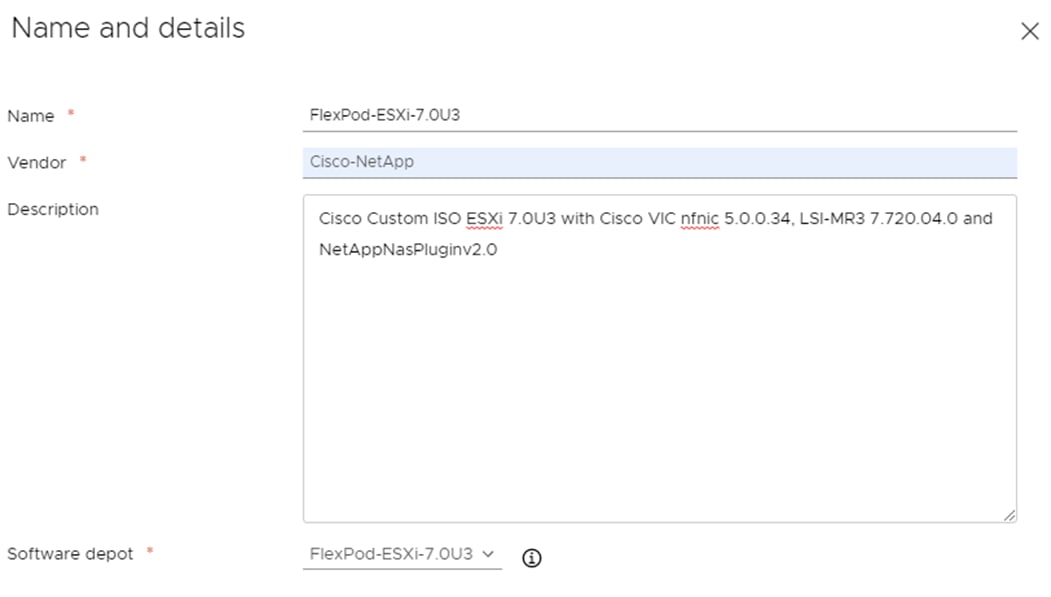
Step 15. Click NEXT.
Step 16. Under Available software packages, check lsi-mr3 7.720.04.00 and uncheck any other lsi-mr3 packages, check NetAppNasPlugin 2.0-15, and check nfnic 5.0.0.34 and uncheck any other nfnic packages. Leave the remaining selections unchanged.
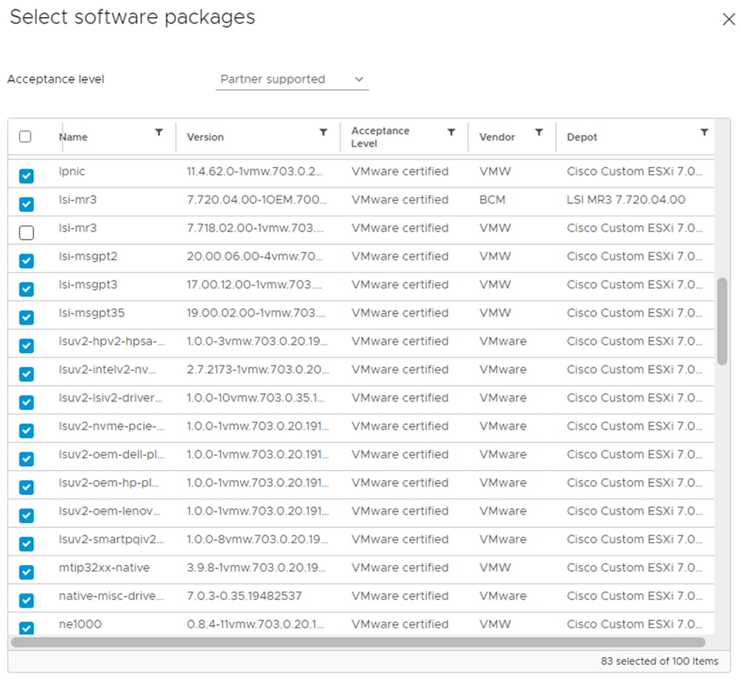
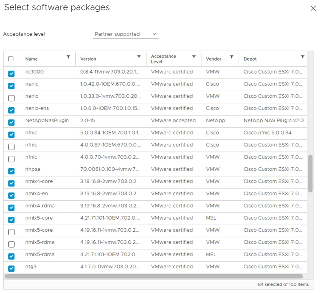
Step 17. Click NEXT.
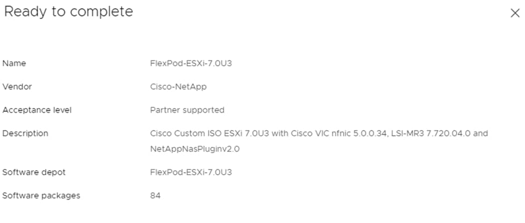
Step 18. Click FINISH to generate the depot.
Step 19. Using the Software Depot pulldown, select the FlexPod-ESXi-7.0U3 (Custom) software depot. Under Image Profiles select the FlexPod-ESXi-7.0U3 image profile. Click EXPORT to export an image profile. ISO should be selected. Click OK to generate a bootable ESXi installable image.
Step 20. Once the Image profile export completes, click DOWNLOAD to download the ISO.
Step 21. Once downloaded, you can rename the ISO to a more descriptive name (for example, FlexPod-ESXi-7.0U3.iso).
Step 22. Optionally, generate the ZIP archive to generate an offline bundle for the FlexPod image using … > Export.
Active IQ Unified Manager User Configuration
Procedure 1. Add Local Users to Active IQ Unified Manager
Step 1. Navigate to Settings > General section and click Users.
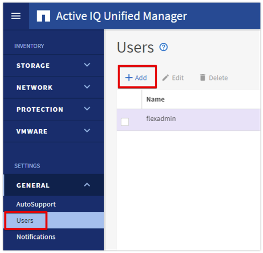
Step 2. Click + Add and complete the requested information:
a. Select Local User for the Type.
b. Enter a username and password.
c. Add the user’s email address.
d. Select the appropriate role for the new user.
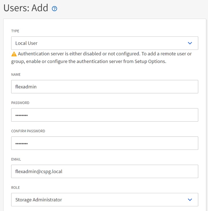
Step 3. Click SAVE to finish adding the new user.
Procedure 2. Configure Remote Authentication
Simplify user management and authentication for Active IQ Unified Manager by integrating it with Microsoft Active Directory.
Note: You must be logged on as the maintenance user created during the installation or another user with Application Administrator privileges to configure remote authentication.
Step 1. Navigate to the General and select Remote Authentication.
Step 2. Select the option to enable Remote Authentication and define a remote user or remote group.
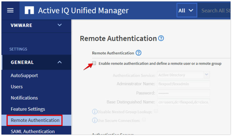
Step 3. Select Active Directory from the authentication service list.
Step 4. Enter the Active Directory service account name and password. The account name can be in the format of domain\user or user@domain.
Step 5. Enter the base DN where your Active Directory users reside.
Step 6. If Active Directory LDAP communications are protected via SSL enable the Use Secure Connection option.
Step 7. Add one or more Active Directory domain controllers by clicking Add and entering the IP or FQDN of the domain controller.
Step 8. Click Save to enable the configuration.
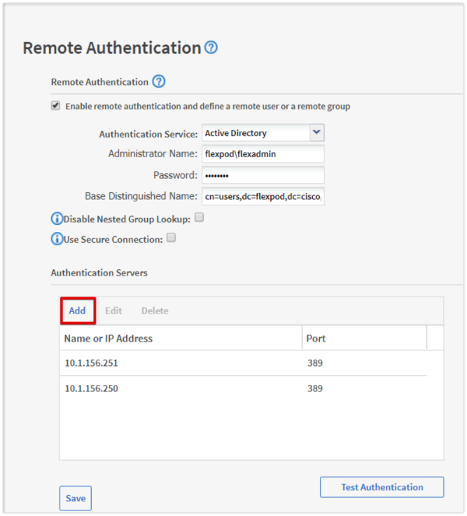
Step 9. Click Test Authentication and enter an Active Directory username and password to test authentication with the Active Directory authentication servers. Click Start.
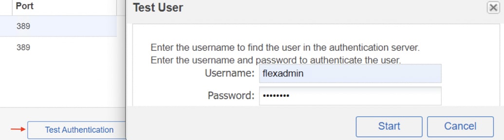
A result message displays indicating authentication was successful:
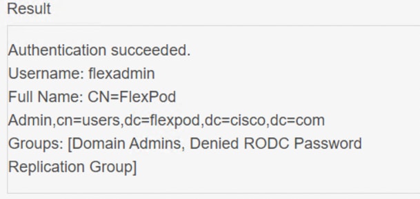
Procedure 3. Add a Remote User to Active IQ Unified Manager
Step 1. Navigate to the General section and select Users.
Step 2. Click Add and select Remote User from the Type drop-down list.
Step 3. Enter the following information into the form:
a. The username of the Active Directory user.
b. Email address of the user.
c. Select the appropriate role for the user.
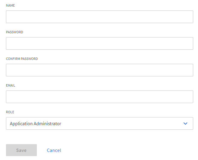
Step 4. Click Save to add the remote user to Active IQ Unified Manager.
Active IQ Unified Manager vCenter Configuration
Active IQ Unified Manager provides visibility into vCenter and the virtual machines running inside the datastores backed by NetApp ONTAP storage. Virtual machines and storage are monitored to enable quick identification of performance issues within the various components of the virtual infrastructure stack.
Note: Before adding vCenter into Active IQ Unified Manager, the log level of the vCenter server must be changed.
Procedure 1. Configure Active IQ Unified Manager vCenter
Step 1. In the vSphere client navigate to Menu > VMs and Templates and select the vCenter instance from the top of the object tree.
Step 2. Click the Configure tab, expand Settings, and select General.
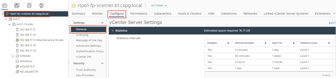
Step 3. Click EDIT.
Step 4. In the pop-up window under Statistics, locate the 5 minutes Interval Duration row and change the setting to Level 3 under the Statistics Level column.
Step 5. Click SAVE.
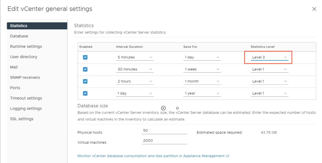
Step 6. Switch to the Active IQ Unified Manager and navigate to the VMware section located under Inventory.
Step 7. Expand VMware and select vCenter.
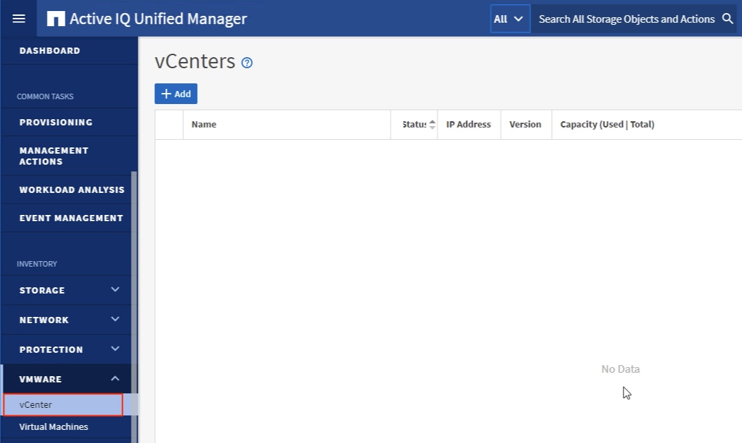
Step 8. Click Add.
Step 9. Enter the VMware vCenter server details and click Save.
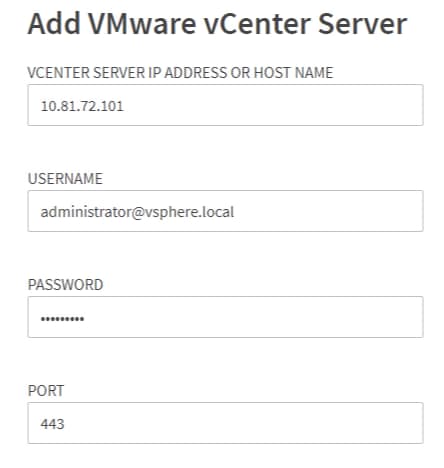
Step 10. A dialog box will appear asking to authorize the certificate. Click Yes to accept the certificate and add the vCenter server.
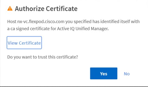
Note: It may take up to 15 minutes to discover vCenter. Performance data can take up to an hour to become available.
Procedure 2. View Virtual Machine Inventory
The virtual machine inventory is automatically added to Active IQ Unified Manager during discovery of the vCenter server. Virtual machines can be viewed in a hierarchical display detailing storage capacity, IOPS and latency for each component in the virtual infrastructure to troubleshoot the source of any performance related issues.
Step 1. Log into NetApp Active IQ Unified Manager.
Step 2. Navigate to the VMware section located under Inventory, expand the section, and click Virtual Machines.
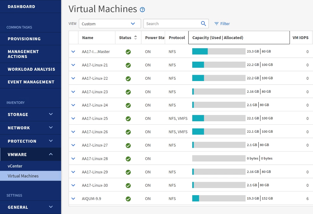
Step 3. Select a VM and click the blue caret to expose the topology view. Review the compute, network, and storage components and their associated IOPS and latency statistics.
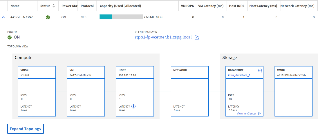
Step 4. Click Expand Topology to see the entire hierarchy of the virtual machine and its virtual disks as it is connected through the virtual infrastructure stack. The VM components are mapped from vSphere and compute through the network to the storage.
NetApp Active IQ is a data-driven service that leverages artificial intelligence and machine learning to provide analytics and actionable intelligence for NetApp ONTAP storage systems. Active IQ uses AutoSupport data to deliver proactive guidance and best practices recommendations to optimize storage performance and minimize risk. Additional Active IQ documentation is available on the Active IQ Documentation Resources web page.
Note: Active IQ is automatically enabled when AutoSupport is configured on the NetApp ONTAP storage controllers.
Procedure 1. Configure NetApp Active IQ
Step 1. Navigate to the Active IQ portal at https://activeiq.netapp.com/.
Step 2. Login with NetApp support account ID.
Step 3. At the Welcome screen enter the cluster name or one of controller serial numbers in the search box. Active IQ will automatically begin searching for the cluster and display results below:
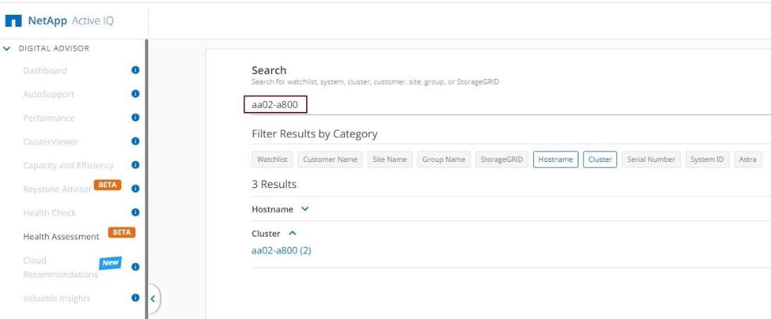
Step 4. Click the <cluster name> (for example, aa02-a800) to launch the dashboard for this cluster.
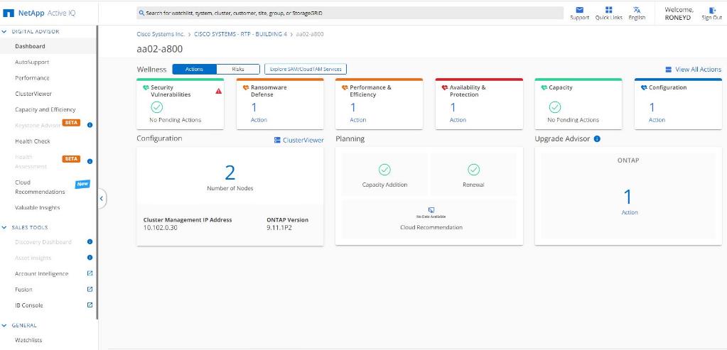
Procedure 2. Add a Watchlist to the Digital Advisor Dashboard
The Active IQ Digital advisor provides a summary dashboard and system wellness score based on the health and risks that Active IQ has identified. The dashboard provides a quick way to identify and get proactive recommendations on how to mitigate risks in the storage environment including links to technical reports and mitigation plans. This procedure details the steps to create a watchlist and launch Digital advisor dashboard for the watchlist.
Step 1. Click GENERAL > Watchlists in the left menu bar.
Step 2. Enter a name for the watchlist.
Step 3. Select the radio button to add systems by serial number and enter the cluster serial numbers to the watchlist.
Step 4. Check the box for Make this my default watchlist if desired.
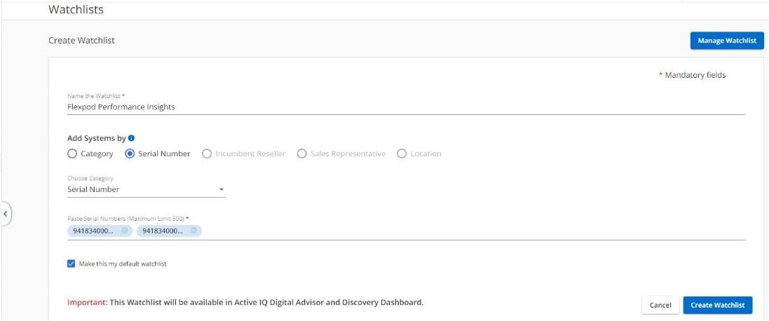
Step 5. Click Create Watchlist.
Step 6. Click GENERAL > Watchlists in the left menu bar again to list the watchlist created.
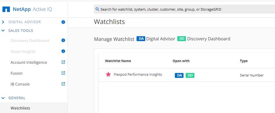
Note: The Discovery Dashboard functionality has been moved to IB (Installed Base) console. Notice that Discovery Dashboard is greyed out under SALES TOOLS.
Step 7. Click the blue box labelled DA to launch the specific watchlist in Digital Advisor Dashboard.
Step 8. Review the enhanced dashboard to learn more about any recommended actions or risks.
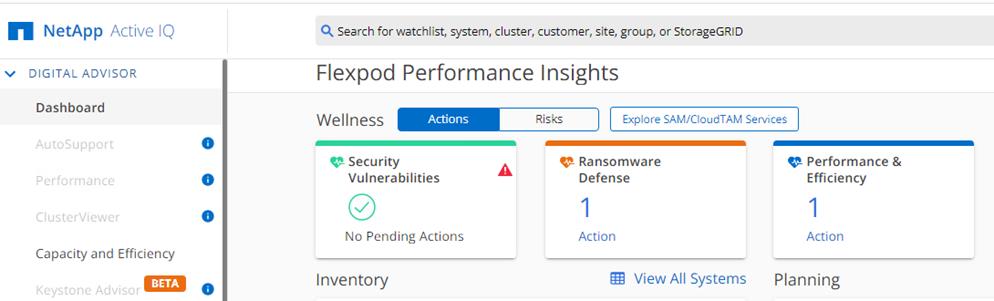
Step 9. Switch between the Actions and Risks tabs to view the risks by category or a list of all risks with their impact and links to corrective actions.
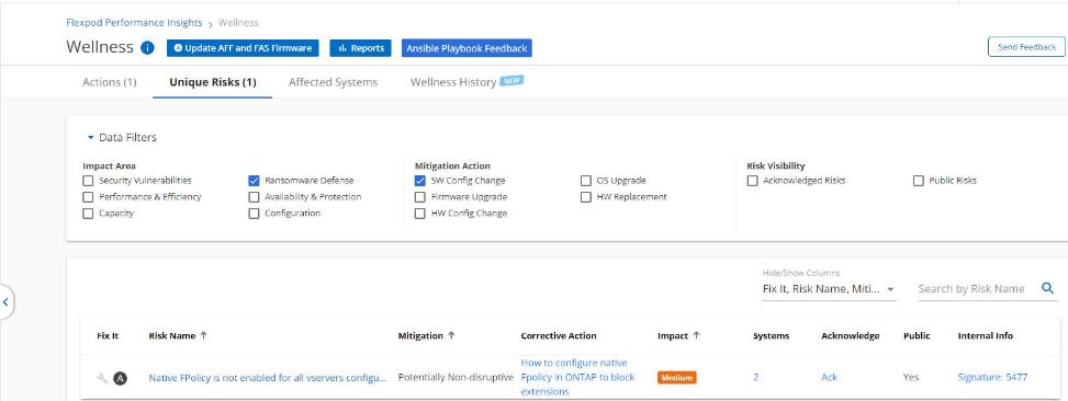
Step 10. Click the links in the Corrective Action column to read the bug information or knowledge base article about how to remediate the risk.
Note: Additional tutorials and video walk-throughs of Active IQ features can be viewed on the following page: https://docs.netapp.com/us-en/active-iq/
Cisco Intersight SaaS Platform
Cisco Intersight SaaS platform maintains customer configurations online. No separate backup was created for the Cisco UCS configuration. If you are using an Intersight Private Virtual Appliance (PVA), ensure that the NetApp SnapCenter Plugin for VMware vSphere is creating periodic backups of this appliance.
Procedure 1. Cisco Nexus and MDS Backups
The configuration of the Cisco Nexus 9000 and Cisco MDS 9132T switches can be backed up manually at any time with the copy command, but automated backups can be enabled using the NX-OS feature scheduler.
An example of setting up automated configuration backups of one of the NX-OS switches is shown below:
feature scheduler
scheduler logfile size 1024
scheduler job name backup-cfg
copy running-config tftp://<server-ip>/$(SWITCHNAME)-cfg.$(TIMESTAMP) vrf management
exit
scheduler schedule name daily
job name backup-cfg
time daily 2:00
end
Note: Using “vrf management” in the copy command is only needed when Mgmt0 interface is part of VRF management.
Step 1. Verify the scheduler job has been correctly setup using following command(s):
show scheduler job
Job Name: backup-cfg
--------------------
copy running-config tftp://10.1.156.150/$(SWITCHNAME)-cfg.$(TIMESTAMP) vrf management
==============================================================================
show scheduler schedule
Schedule Name : daily
---------------------------
User Name : admin
Schedule Type : Run every day at 2 Hrs 0 Mins
Last Execution Time : Yet to be executed
-----------------------------------------------
Job Name Last Execution Status
-----------------------------------------------
backup-cfg -NA-
==============================================================================
The documentation for the feature scheduler can be found here: https://www.cisco.com/c/en/us/td/docs/dcn/nx-os/nexus9000/102x/configuration/system-management/cisco-nexus-9000-series-nx-os-system-management-configuration-guide-102x/m-configuring-the-scheduler-10x.html
Procedure 2. VMware VCSA Backup
Note: Basic scheduled backup for the vCenter Server Appliance is available within the native capabilities of the VCSA.
Step 1. Connect to the VCSA Console at https://<VCSA IP>:5480.
Step 2. Log in as root.
Step 3. Click Backup in the list to open the Backup Schedule Dialogue.
Step 4. To the right of Backup Schedule, click CONFIGURE.
Step 5. Specify the following:
a. The Backup location with the protocol to use (FTPS,HTTPS,SFTP,FTP,NFS,SMB, and HTTP)
b. The Username and Password. For the NFS (NFS3) example captured below, the username is root and use a random password because NFSv3 sys security was configured.
c. The Number of backups to retain.
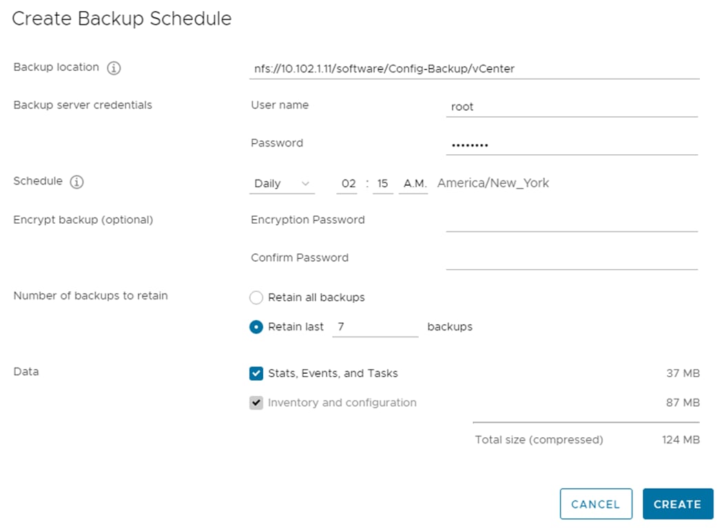
Step 6. Click CREATE.
The Backup Schedule Status should now show Enabled.
Step 7. To test the backup setup, select BACKUP NOW and select “Use backup location and user name from backup schedule” to test the backup location.
Step 8. Restoration can be initiated with the backed-up files using the Restore function of the VCSA 7.0 Installer.
AAA—Authentication, Authorization, and Accounting
ACP—Access-Control Policy
ACI—Cisco Application Centric Infrastructure
ACK—Acknowledge or Acknowledgement
ACL—Access-Control List
AD—Microsoft Active Directory
AFI—Address Family Identifier
AMP—Cisco Advanced Malware Protection
AP—Access Point
API—Application Programming Interface
APIC— Cisco Application Policy Infrastructure Controller (ACI)
ASA—Cisco Adaptative Security Appliance
ASM—Any-Source Multicast (PIM)
ASR—Aggregation Services Router
Auto-RP—Cisco Automatic Rendezvous Point protocol (multicast)
AVC—Application Visibility and Control
BFD—Bidirectional Forwarding Detection
BGP—Border Gateway Protocol
BMS—Building Management System
BSR—Bootstrap Router (multicast)
BYOD—Bring Your Own Device
CAPWAP—Control and Provisioning of Wireless Access Points Protocol
CDP—Cisco Discovery Protocol
CEF—Cisco Express Forwarding
CMD—Cisco Meta Data
CPU—Central Processing Unit
CSR—Cloud Services Routers
CTA—Cognitive Threat Analytics
CUWN—Cisco Unified Wireless Network
CVD—Cisco Validated Design
CYOD—Choose Your Own Device
DC—Data Center
DHCP—Dynamic Host Configuration Protocol
DM—Dense-Mode (multicast)
DMVPN—Dynamic Multipoint Virtual Private Network
DMZ—Demilitarized Zone (firewall/networking construct)
DNA—Cisco Digital Network Architecture
DNS—Domain Name System
DORA—Discover, Offer, Request, ACK (DHCP Process)
DWDM—Dense Wavelength Division Multiplexing
ECMP—Equal Cost Multi Path
EID—Endpoint Identifier
EIGRP—Enhanced Interior Gateway Routing Protocol
EMI—Electromagnetic Interference
ETR—Egress Tunnel Router (LISP)
EVPN—Ethernet Virtual Private Network (BGP EVPN with VXLAN data plane)
FHR—First-Hop Router (multicast)
FHRP—First-Hop Redundancy Protocol
FMC—Cisco Firepower Management Center
FTD—Cisco Firepower Threat Defense
GBAC—Group-Based Access Control
GbE—Gigabit Ethernet
Gbit/s—Gigabits Per Second (interface/port speed reference)
GRE—Generic Routing Encapsulation
GRT—Global Routing Table
HA—High-Availability
HQ—Headquarters
HSRP—Cisco Hot-Standby Routing Protocol
HTDB—Host-tracking Database (SD-Access control plane node construct)
IBNS—Identity-Based Networking Services (IBNS 2.0 is the current version)
ICMP— Internet Control Message Protocol
IDF—Intermediate Distribution Frame; essentially a wiring closet.
IEEE—Institute of Electrical and Electronics Engineers
IETF—Internet Engineering Task Force
IGP—Interior Gateway Protocol
IID—Instance-ID (LISP)
IOE—Internet of Everything
IoT—Internet of Things
IP—Internet Protocol
IPAM—IP Address Management
IPS—Intrusion Prevention System
IPSec—Internet Protocol Security
ISE—Cisco Identity Services Engine
ISR—Integrated Services Router
IS-IS—Intermediate System to Intermediate System routing protocol
ITR—Ingress Tunnel Router (LISP)
LACP—Link Aggregation Control Protocol
LAG—Link Aggregation Group
LAN—Local Area Network
L2 VNI—Layer 2 Virtual Network Identifier; as used in SD-Access Fabric, a VLAN.
L3 VNI— Layer 3 Virtual Network Identifier; as used in SD-Access Fabric, a VRF.
LHR—Last-Hop Router (multicast)
LISP—Location Identifier Separation Protocol
MAC—Media Access Control Address (OSI Layer 2 Address)
MAN—Metro Area Network
MEC—Multichassis EtherChannel, sometimes referenced as MCEC
MDF—Main Distribution Frame; essentially the central wiring point of the network.
MnT—Monitoring and Troubleshooting Node (Cisco ISE persona)
MOH—Music on Hold
MPLS—Multiprotocol Label Switching
MR—Map-resolver (LISP)
MS—Map-server (LISP)
MSDP—Multicast Source Discovery Protocol (multicast)
MTU—Maximum Transmission Unit
NAC—Network Access Control
NAD—Network Access Device
NAT—Network Address Translation
NBAR—Cisco Network-Based Application Recognition (NBAR2 is the current version).
NFV—Network Functions Virtualization
NSF—Non-Stop Forwarding
OSI—Open Systems Interconnection model
OSPF—Open Shortest Path First routing protocol
OT—Operational Technology
PAgP—Port Aggregation Protocol
PAN—Primary Administration Node (Cisco ISE persona)
PCI DSS—Payment Card Industry Data Security Standard
PD—Powered Devices (PoE)
PETR—Proxy-Egress Tunnel Router (LISP)
PIM—Protocol-Independent Multicast
PITR—Proxy-Ingress Tunnel Router (LISP)
PnP—Plug-n-Play
PoE—Power over Ethernet (Generic term, may also refer to IEEE 802.3af, 15.4W at PSE)
PoE+—Power over Ethernet Plus (IEEE 802.3at, 30W at PSE)
PSE—Power Sourcing Equipment (PoE)
PSN—Policy Service Node (Cisco ISE persona)
pxGrid—Platform Exchange Grid (Cisco ISE persona and publisher/subscriber service)
PxTR—Proxy-Tunnel Router (LISP – device operating as both a PETR and PITR)
QoS—Quality of Service
RADIUS—Remote Authentication Dial-In User Service
REST—Representational State Transfer
RFC—Request for Comments Document (IETF)
RIB—Routing Information Base
RLOC—Routing Locator (LISP)
RP—Rendezvous Point (multicast)
RP—Redundancy Port (WLC)
RP—Route Processer
RPF—Reverse Path Forwarding
RR—Route Reflector (BGP)
RTT—Round-Trip Time
SA—Source Active (multicast)
SAFI—Subsequent Address Family Identifiers (BGP)
SD—Software-Defined
SDA—Cisco Software Defined-Access
SDN—Software-Defined Networking
SFP—Small Form-Factor Pluggable (1 GbE transceiver)
SFP+— Small Form-Factor Pluggable (10 GbE transceiver)
SGACL—Security-Group ACL
SGT—Scalable Group Tag, sometimes reference as Security Group Tag
SM—Spare-mode (multicast)
SNMP—Simple Network Management Protocol
SSID—Service Set Identifier (wireless)
SSM—Source-Specific Multicast (PIM)
SSO—Stateful Switchover
STP—Spanning-tree protocol
SVI—Switched Virtual Interface
SVL—Cisco StackWise Virtual
SWIM—Software Image Management
SXP—Scalable Group Tag Exchange Protocol
Syslog—System Logging Protocol
TACACS+—Terminal Access Controller Access-Control System Plus
TCP—Transmission Control Protocol (OSI Layer 4)
UCS— Cisco Unified Computing System
UDP—User Datagram Protocol (OSI Layer 4)
UPoE—Cisco Universal Power Over Ethernet (60W at PSE)
UPoE+— Cisco Universal Power Over Ethernet Plus (90W at PSE)
URL—Uniform Resource Locator
VLAN—Virtual Local Area Network
VM—Virtual Machine
VN—Virtual Network, analogous to a VRF in SD-Access
VNI—Virtual Network Identifier (VXLAN)
vPC—virtual Port Channel (Cisco Nexus)
VPLS—Virtual Private LAN Service
VPN—Virtual Private Network
VPNv4—BGP address family that consists of a Route-Distinguisher (RD) prepended to an IPv4 prefix
VPWS—Virtual Private Wire Service
VRF—Virtual Routing and Forwarding
VSL—Virtual Switch Link (Cisco VSS component)
VSS—Cisco Virtual Switching System
VXLAN—Virtual Extensible LAN
WAN—Wide-Area Network
WLAN—Wireless Local Area Network (generally synonymous with IEEE 802.11-based networks)
WoL—Wake-on-LAN
xTR—Tunnel Router (LISP – device operating as both an ETR and ITR)
This glossary addresses some terms used in this document, for the purposes of aiding understanding. This is not a complete list of all multicloud terminology. Some Cisco product links are supplied here also, where considered useful for the purposes of clarity, but this is by no means intended to be a complete list of all applicable Cisco products.
| aaS/XaaS (IT capability provided as a Service) |
Some IT capability, X, provided as a service (XaaS). Some benefits are:
● The provider manages the design, implementation, deployment, upgrades, resiliency, scalability, and overall delivery of the service and the infrastructure that supports it.
● There are very low barriers to entry, so that services can be quickly adopted and dropped in response to business demand, without the penalty of inefficiently utilized CapEx.
● The service charge is an IT OpEx cost (pay-as-you-go), whereas the CapEx and the service infrastructure is the responsibility of the provider.
● Costs are commensurate to usage and hence more easily controlled with respect to business demand and outcomes.
Such services are typically implemented as “microservices,” which are accessed via REST APIs. This architectural style supports composition of service components into systems. Access to and management of aaS assets is via a web GUI and/or APIs, such that Infrastructure-as-code (IaC) techniques can be used for automation, for example, Ansible and Terraform. The provider can be any entity capable of implementing an aaS “cloud-native” architecture. The cloud-native architecture concept is well-documented and supported by open-source software and a rich ecosystem of services such as training and consultancy. The provider can be an internal IT department or any of many third-party companies using and supporting the same open-source platforms. Service access control, integrated with corporate IAM, can be mapped to specific users and business activities, enabling consistent policy controls across services, wherever they are delivered from. |
| Ansible |
An infrastructure automation tool, used to implement processes for instantiating and configuring IT service components, such as VMs on an IaaS platform. Supports the consistent execution of processes defined in YAML “playbooks” at scale, across multiple targets. Because the Ansible artefacts (playbooks) are text-based, they can be stored in a Source Code Management (SCM) system, such as GitHub. This allows for software development like processes to be applied to infrastructure automation, such as, Infrastructure-as-code (see IaC below). |
| AWS (Amazon Web Services) |
Provider of IaaS and PaaS. |
| Azure |
Microsoft IaaS and PaaS. |
| Co-located data center |
“A colocation center (CoLo)…is a type of data center where equipment, space, and bandwidth are available for rental to retail customers. Colocation facilities provide space, power, cooling, and physical security for the server, storage, and networking equipment of other firms and also connect them to a variety of telecommunications and network service providers with a minimum of cost and complexity.” |
| Containers (Docker) |
A (Docker) container is a means to create a package of code for an application and its dependencies, such that the application can run on different platforms which support the Docker environment. In the context of aaS, microservices are typically packaged within Linux containers orchestrated by Kubernetes (K8s). https://www.cisco.com/c/en/us/products/cloud-systems-management/containerplatform/index.html |
| DevOps |
The underlying principle of DevOps is that the application development and operations teams should work closely together, ideally within the context of a toolchain that automates the stages of development, test, deployment, monitoring, and issue handling. DevOps is closely aligned with IaC, continuous integration and deployment (CI/CD), and Agile software development practices. |
| Edge compute |
Edge compute is the idea that it can be more efficient to process data at the edge of a network, close to the endpoints that originate that data, or to provide virtualized access services, such as at the network edge. This could be for reasons related to low latency response, reduction of the amount of unprocessed data being transported, efficiency of resource utilization, and so on. The generic label for this is Multi-access Edge Computing (MEC), or Mobile Edge Computing for mobile networks specifically. From an application experience perspective, it is important to be able to utilize, at the edge, the same operations model, processes, and tools used for any other compute node in the system. |
| IaaS (Infrastructure as-a-Service) |
Infrastructure components provided aaS, located in data centers operated by a provider, typically accessed over the public Internet. IaaS provides a base platform for the deployment of workloads, typically with containers and Kubernetes (K8s). |
| IaC (Infrastructure as-Code) |
Given the ability to automate aaS via APIs, the implementation of the automation is typically via Python code, Ansible playbooks, and similar. These automation artefacts are programming code that define how the services are consumed. As such, they can be subject to the same code management and software development regimes as any other body of code. This means that infrastructure automation can be subject to all of the quality and consistency benefits, CI/CD, traceability, automated testing, compliance checking, and so on, that could be applied to any coding project. |
| IAM (Identity and Access Management) |
IAM is the means to control access to IT resources so that only those explicitly authorized to access given resources can do so. IAM is an essential foundation to a secure multicloud environment. |
| IBM (Cloud) |
IBM IaaS and PaaS. |
| Intersight |
Cisco Intersight is a Software-as-a-Service (SaaS) infrastructure lifecycle management platform that delivers simplified configuration, deployment, maintenance, and support. https://www.cisco.com/c/en/us/products/servers-unified-computing/intersight/index.html |
| GCP (Google Cloud Platform) |
Google IaaS and PaaS. |
| Kubernetes (K8s) |
Kubernetes is an open-source system for automating deployment, scaling, and management of containerized applications. |
| Microservices |
A microservices architecture is characterized by processes implementing fine-grained services, typically exposed via REST APIs and which can be composed into systems. The processes are often container-based, and the instantiation of the services often managed with Kubernetes. Microservices managed in this way are intrinsically well suited for deployment into IaaS environments, and as such, are the basis of a cloud native architecture. |
| PaaS (Platform-as-a-Service) |
PaaS is a layer of value-add services, typically for application development, deployment, monitoring, and general lifecycle management. The use of IaC with IaaS and PaaS is very closely associated with DevOps practices. |
| Private on-premises data center |
A data center infrastructure housed within an environment owned by a given enterprise is distinguished from other forms of data center, with the implication that the private data center is more secure, given that access is restricted to those authorized by the enterprise. Thus, circumstances can arise where very sensitive IT assets are only deployed in a private data center, in contrast to using public IaaS. For many intents and purposes, the underlying technology can be identical, allowing for hybrid deployments where some IT assets are privately deployed but also accessible to other assets in public IaaS. IAM, VPNs, firewalls, and similar are key technologies needed to underpin the security of such an arrangement. |
| REST API |
Representational State Transfer (REST) APIs is a generic term for APIs accessed over HTTP(S), typically transporting data encoded in JSON or XML. REST APIs have the advantage that they support distributed systems, communicating over HTTP, which is a well-understood protocol from a security management perspective. REST APIs are another element of a cloud-native applications architecture, alongside microservices. https://en.wikipedia.org/wiki/Representational_state_transfer |
| SaaS (Software-as-a-Service) |
End-user applications provided “aaS” over the public Internet, with the underlying software systems and infrastructure owned and managed by the provider. |
| SAML (Security Assertion Markup Language) |
Used in the context of Single-Sign-On (SSO) for exchanging authentication and authorization data between an identity provider, typically an IAM system, and a service provider (some form of SaaS). The SAML protocol exchanges XML documents that contain security assertions used by the aaS for access control decisions. https://en.wikipedia.org/wiki/Security_Assertion_Markup_Language |
| Terraform |
An open-source IaC software tool for cloud services, based on declarative configuration files. |
For comments and suggestions about this guide and related guides, join the discussion on Cisco Community at https://cs.co/en-cvds.
CVD Program
ALL DESIGNS, SPECIFICATIONS, STATEMENTS, INFORMATION, AND RECOMMENDATIONS (COLLECTIVELY, "DE-SIGNS") IN THIS MANUAL ARE PRESENTED "AS IS," WITH ALL FAULTS. CISCO AND ITS SUPPLIERS DISCLAIM ALL WAR-RANTIES, INCLUDING, WITHOUT LIMITATION, THE WARRANTY OF MERCHANTABILITY, FITNESS FOR A PARTICULAR PURPOSE AND NONINFRINGEMENT OR ARISING FROM A COURSE OF DEALING, USAGE, OR TRADE PRACTICE. IN NO EVENT SHALL CISCO OR ITS SUPPLIERS BE LIABLE FOR ANY INDIRECT, SPECIAL, CONSEQUENTIAL, OR INCIDENTAL DAMAGES, INCLUDING, WITHOUT LIMITATION, LOST PROFITS OR LOSS OR DAMAGE TO DATA ARISING OUT OF THE USE OR INABILITY TO USE THE DESIGNS, EVEN IF CISCO OR ITS SUPPLIERS HAVE BEEN ADVISED OF THE POSSIBILITY OF SUCH DAMAGES.
THE DESIGNS ARE SUBJECT TO CHANGE WITHOUT NOTICE. USERS ARE SOLELY RESPONSIBLE FOR THEIR APPLICA-TION OF THE DESIGNS. THE DESIGNS DO NOT CONSTITUTE THE TECHNICAL OR OTHER PROFESSIONAL ADVICE OF CISCO, ITS SUPPLIERS OR PARTNERS. USERS SHOULD CONSULT THEIR OWN TECHNICAL ADVISORS BEFORE IMPLE-MENTING THE DESIGNS. RESULTS MAY VARY DEPENDING ON FACTORS NOT TESTED BY CISCO.
CCDE, CCENT, Cisco Eos, Cisco Lumin, Cisco Nexus, Cisco StadiumVision, Cisco TelePresence, Cisco WebEx, the Cisco logo, DCE, and Welcome to the Human Network are trademarks; Changing the Way We Work, Live, Play, and Learn and Cisco Store are service marks; and Access Registrar, Aironet, AsyncOS, Bringing the Meeting To You, Catalyst, CCDA, CCDP, CCIE, CCIP, CCNA, CCNP, CCSP, CCVP, Cisco, the Cisco Certified Internetwork Expert logo, Cisco IOS, Cisco Press, Cisco Systems, Cisco Systems Capital, the Cisco Systems logo, Cisco Unified Computing System (Cisco UCS), Cisco UCS B-Series Blade Servers, Cisco UCS C-Series Rack Servers, Cisco UCS S-Series Storage Servers, Cisco UCS Manager, Cisco UCS Management Software, Cisco Unified Fabric, Cisco Application Centric Infrastructure, Cisco Nexus 9000 Series, Cisco Nexus 7000 Series. Cisco Prime Data Center Network Manager, Cisco NX-OS Software, Cis-co MDS Series, Cisco Unity, Collaboration Without Limitation, EtherFast, EtherSwitch, Event Center, Fast Step, Follow Me Browsing, FormShare, GigaDrive, HomeLink, Internet Quotient, IOS, iPhone, iQuick Study, LightStream, Linksys, MediaTone, MeetingPlace, MeetingPlace Chime Sound, MGX, Networkers, Networking Academy, Network Registrar, PCNow, PIX, PowerPanels, ProConnect, ScriptShare, SenderBase, SMARTnet, Spectrum Expert, StackWise, The Fastest Way to Increase Your Internet Quotient, TransPath, WebEx, and the WebEx logo are registered trade-marks of Cisco Systems, Inc. and/or its affiliates in the United States and certain other countries. (LDW_MP2)
All other trademarks mentioned in this document or website are the property of their respective owners. The use of the word partner does not imply a partnership relationship between Cisco and any other company. (0809R)