Deploy FlexPod Datacenter for Microsoft SQL Server 2019 with VMware 7.0 on Cisco UCS B200 M6 and NetApp ONTAP 9.8
Available Languages
Bias-Free Language
The documentation set for this product strives to use bias-free language. For the purposes of this documentation set, bias-free is defined as language that does not imply discrimination based on age, disability, gender, racial identity, ethnic identity, sexual orientation, socioeconomic status, and intersectionality. Exceptions may be present in the documentation due to language that is hardcoded in the user interfaces of the product software, language used based on RFP documentation, or language that is used by a referenced third-party product. Learn more about how Cisco is using Inclusive Language.
A data center solution must embrace technology advancements in various areas, such as computing, networking, and storage technologies, to address rapidly changing requirements and the challenges of IT organizations. The current industry trend in data center design is toward shared infrastructure. By using virtualization along with prevalidated IT platforms, enterprise customers have embarked on the journey to the cloud by moving away from application silos and toward shared infrastructure that can be quickly deployed, thereby increasing agility and reducing costs. Cisco and NetApp have partnered to deliver FlexPod, which uses best-in-class storage, server, and network components to serve as the foundation for a variety of workloads, enabling efficient architectural designs that can be quickly and confidently deployed.
This document describes a FlexPod reference architecture using the latest hardware and software products and provides deployment recommendations for hosting Microsoft SQL Server 2019 databases in VMware ESXi virtualized environments.
The solution is built on the Cisco Unified Computing System™ (Cisco UCS®) with Software Release 4.2(1d) to support Cisco UCS hardware, including Cisco UCS B200 M6 Blade Servers, Cisco UCS 6400 Series Fabric Interconnects, Cisco Nexus® 9000 Series Switches, and NetApp AFF storage arrays.
This section introduces the solution discussed in this document.
The current IT industry is witnessing wide-ranging transformations in data center solutions. In recent years, there has been considerable interest in prevalidated and engineered data center solutions. Introduction of virtualization technology in key areas has significantly affected the design principles and architectures of these solutions. It has opened the way for many applications running on bare-metal systems to migrate to these new virtualized integrated solutions.
FlexPod is one such prevalidated and engineered data center solution designed to address the rapidly changing needs of IT organizations. Cisco and NetApp have partnered to deliver FlexPod, which uses best-in-class computing, networking, and storage components to serve as the foundation for a variety of enterprise workloads, including databases, enterprise resource planning (ERP), customer relationship management (CRM), and web applications, among others.
The consolidation of IT applications, particularly databases, has generated considerable interest in recent years. The most widely adopted and deployed database platform over several years, Microsoft SQL Server databases, have become the victim of a common IT challenge: database sprawl. Some of the challenges of SQL Server sprawl include underutilized servers, incorrect licensing, security concerns, management concerns, and huge operational costs. Hence, SQL Server databases are excellent candidates for migration and consolidation on a more robust, flexible, and resilient platform. This document discusses a FlexPod reference architecture for deploying and consolidating SQL Server databases.
The audience for this document includes sales engineers, field consultants, database administrators, professional services, IT managers, partner engineers, and customers who want to take advantage of an infrastructure built to deliver IT efficiency and enable IT innovation. The reader should have prior knowledge of FlexPod and its components.
This document describes a FlexPod reference architecture and provides step-by-step implementation guidelines for deploying Microsoft SQL Server 2019 databases on FlexPod systems.
The following software and hardware products distinguish the reference architecture from previous releases:
● Microsoft SQL Server 2019 deployment on Microsoft Windows Server 2019 guest virtual machines running on VMware vSphere 7.0 clusters
● Support for the Cisco UCS 4.2(1d) unified software release and Cisco UCS B200 M6 Blade Servers with Third Generation (3rd Gen) Intel® Xeon® Scalable processors and the Cisco Virtual Interface Card (VIC) 1400
● Support for the latest Cisco UCS 6454 Fabric Interconnects and Cisco UCS 2408 Fabric Extender
● 100 Gbps Ethernet connectivity for storage access over the Small Computer System Interface over IP (iSCSI) protocol
● NetApp All Flash A800 storage with Data ONTAP 9.8 and NetApp SnapCenter 4.5 for virtual machine and SQL Server database backup and recovery
● NetApp ONTAP tools plug-in (ONTAP 9.8) for datastore storage provisioning to VMware ESXi hosts
● NetApp SnapCenter 4.5 for virtual machine backup and recovery
● NetApp SnapCenter 4.5 for SQL Server database backup, recovery, protection, and cloning
● NetApp SnapCenter 4.5 for storage provisioning to Windows virtual machines for SQL Server databases and log files
● Direct storage connectivity for SQL Server database volumes using in-guest software iSCSI initiator
● Cisco Intersight™ software as a service (SaaS) for Cisco UCS infrastructure monitoring and management
This section provides an overview of the various technologies used in this solution.
FlexPod solution
FlexPod is a best-practices data center architecture that includes the following components (Figure 1):
● Cisco Unified Computing System (Cisco UCS)
● Cisco Nexus switches (for iSCSI, Network File System [NFS], and Non-Volatile Memory Express over Fabrics [NVMeoF]: RDMA over Converged Ethernet [RoCE]–based implementation)
● Cisco® MDS switches (for Fibre Channel and NVMeoF: Fibre Channel–based implementation)
● NetApp All Flash FAS (AFF) systems
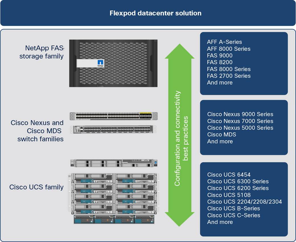
FlexPod component families
These components are connected and configured according to the best practices of Cisco and NetApp and provide an excellent platform for running multiple enterprise workloads with confidence. The reference architecture explained in this document uses Cisco Nexus 9000 Series Switches. One of the main benefits of FlexPod is the capability to maintain consistency at scale, including scale-up and scale-out deployments. Each of the component families shown in Figure 1 (Cisco UCS, Cisco Nexus, and NetApp storage systems) offers platform and resource options to scale the infrastructure up or down, while supporting the features and functions that are required under the configuration and connectivity best practices for FlexPod.
As customers transition to shared infrastructure or cloud computing, they face challenges related to initial transition glitches, return on investment (ROI) analysis, infrastructure management, future growth plans, and other factors. By introducing standardization, FlexPod helps customers mitigate the risk and uncertainty involved in planning, designing, and implementing a new data center infrastructure. The result is a more predictive and adaptable architecture capable of meeting and exceeding customers' IT demands.
The following list summarizes the unique features and benefits that the FlexPod system provides for consolidating SQL Server database deployments:
● Support for 3rd Gen Intel Xeon Scalable family CPUs and Cisco UCS B200 M6 blades, enabling consolidation of more SQL Server virtual machines and thereby achieving higher consolidation ratios and reducing total cost of ownership (TCO) and achieving quick ROI
● 100 Gigabit Ethernet connectivity and storage connectivity using Cisco UCS fourth-generation fabric interconnects, Cisco Nexus 9000 Series Switches, and NetApp AFF A800 storage arrays
● Nondisruptive policy-based management of infrastructure using Cisco UCS Manager.
● Fast I/O performance using NetApp All Flash FAS storage arrays and complete virtual machine protection by using NetApp Snapshot technology and direct storage access to SQL Server virtual machines using the in-guest iSCSI initiator
FlexPod: Cisco and NetApp verified and validated architecture
Cisco and NetApp have thoroughly validated and verified the FlexPod solution architecture and its many use cases while creating a portfolio of detailed documentation, information, and references to assist customers in transforming their data centers to this shared infrastructure model. This portfolio includes the following items:
● Best-practices architectural design
● Workload sizing and scaling guidance
● Implementation and deployment instructions
● Technical specifications (rules for FlexPod configuration)
● Frequently asked questions (FAQs)
● Cisco Validated Designs and NetApp Verified Architectures (NVAs) focused on several use cases
Cisco and NetApp have also built a robust and experienced support team focused on FlexPod solutions, from customer accounts and technical sales representatives to professional services and technical support engineers. The cooperative support program extended by Cisco and NetApp provides customers and channel service partners with direct access to technical experts who collaborate with cross-vendors and have access to shared lab resources to resolve potential issues. FlexPod supports tight integration with virtualized cloud infrastructures, making it a logical choice for a long-term investment.
Out-of-the-box infrastructure high availability
FlexPod is a highly available and scalable infrastructure that IT can evolve over time to support multiple physical and virtual application workloads. FlexPod has no single point of failure at any level, from the server through the network, to storage. The fabric is fully redundant and scalable and provides seamless traffic failover should any individual component fail at the physical or virtual layer.
FlexPod addresses four main design principles: availability, scalability, flexibility, and manageability. The architecture goals are as follows:
● Application availability: Helps ensure that services are accessible and ready to use
● Scalability: Addresses increasing demands with appropriate resources
● Flexibility: Provides new services and recovers resources without requiring infrastructure modification
● Manageability: Facilitates efficient infrastructure operations through open standards and APIs
The following sections provide a brief introduction to the various hardware and software components used in this solution.
Cisco Unified Computing System
Cisco UCS is a next-generation solution for blade and rack server computing. The system integrates a low-latency lossless 10, 25, 40, or100 Gigabit Ethernet unified network fabric with enterprise-class x86-architecture servers. The system is an integrated, scalable, multi chassis platform in which all resources participate in a unified management domain. Cisco UCS accelerates the delivery of new services simply, reliably, and securely through end-to-end provisioning and migration support for both virtualized and nonvirtualized systems.
Cisco UCS provides:
● Comprehensive management
● Radical simplification
● High performance
Cisco UCS consists of the following components:
● Computing: The system is based on an entirely new class of computing system that incorporates rack-mount and blade servers based on the Intel Xeon Scalable processors product family.
● Network: The system is integrated onto a low-latency, lossless, 10/25/40/100-Gbps unified network fabric. This network foundation consolidates LANs, SANs, and high-performance computing (HPC) networks, which are separate networks today. The unified fabric lowers costs by reducing the number of network adapters, switches, and cables and by decreasing power and cooling requirements.
● Virtualization: The system unleashes the full potential of virtualization by enhancing the scalability, performance, and operational control of virtual environments. Cisco security, policy enforcement, and diagnostic features are now extended into virtualized environments to better support changing business and IT requirements.
● Storage access: The system provides consolidated access to both SAN storage and network-attached storage (NAS) over the unified fabric. It is also an excellent system for software-defined storage (SDS). Combining the benefits of a single framework for managing both the computing and storage servers in a single pane, quality of service (QoS) can be implemented if needed to inject I/O throttling into the system as well as workload isolation. In addition, server administrators can pre-assign storage-access policies to storage resources for simplified storage connectivity and management, leading to increased productivity. In addition to external storage, both rack and blade servers have internal storage, which can be accessed through built-in hardware RAID controllers. With storage profile and disk configuration policy configured in Cisco UCS Manager, storage needs for the host OS and application data are fulfilled by user-defined RAID groups for high availability and better performance.
● Management: The system uniquely integrates all system components to enable the entire solution to be managed as a single entity by Cisco UCS Manager. Cisco UCS Manager has an intuitive GUI, a command-line interface (CLI), and a powerful scripting library module for Microsoft PowerShell built on a robust API to manage all system configuration and operations.
Cisco UCS fuses access-layer networking and servers. This high-performance next-generation server system provides a data center with a high degree of workload agility and scalability.
Cisco UCS Manager provides unified, embedded management for all software and hardware components of Cisco UCS. Using Cisco Single Connect technology, it manages, controls, and administers multiple chassis for thousands of virtual machines. Administrators use the software to manage the entire Cisco Unified Computing System as a single logical entity through an intuitive GUI, CLI, or XML API. Cisco UCS Manager resides on a pair of Cisco UCS 6400 Series Fabric Interconnects using a clustered, active-standby configuration for high availability.
Cisco UCS Manager offers a unified embedded management interface that integrates server, network, and storage resources. Cisco UCS Manager performs auto discovery to detect inventory and manage and provision system components that are added or changed. It offers a comprehensive set of XML APIs for third-party integration, exposes 9000 points of integration, and facilitates custom development for to achieve automation, orchestration, and new levels of system visibility and control.
Service profiles benefit both virtualized and nonvirtualized environments and increase the mobility of nonvirtualized servers, such as when moving workloads from server to server or taking a server offline for service or upgrade. Profiles can also be used in conjunction with virtualization clusters to bring new resources online easily, complementing existing virtual machine mobility.
For more information about Cisco UCS Manager, see https://www.cisco.com/c/en/us/products/servers-unified-computing/ucs-manager/index.html.
Cisco UCS fabric interconnects
Fabric interconnects provide a single point for connectivity and management for the entire system. Typically deployed as an active-active pair, the system’s fabric interconnects integrate all components into a single, highly available management domain controlled by Cisco UCS Manager. The fabric interconnects manage all I/O efficiently and securely at a single point, resulting in deterministic I/O latency regardless of a server’s or virtual machine’s topological location in the system.
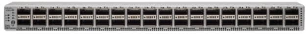
Cisco UCS 6400 Series supports low-latency, lossless 10/25/40/100 Gigabit Ethernet unified network fabric capabilities, which increase the reliability, efficiency, and scalability of Ethernet networks. The fabric interconnects support multiple traffic classes over a lossless Ethernet fabric from the server through the fabric interconnect. Significant TCO savings come from a Fibre Channel over Ethernet (FCoE)–optimized server design in which network interface cards (NICs), host bus adapters (HBAs), cables, and switches can be consolidated. The Cisco UCS 6454 (Figure 2) is a one-rack-unit (1RU) fabric interconnect 10, 25, 40, and 100 Gigabit Ethernet; FCoE; and Fibre Channel switch offering up to 3.82 Tbps throughput and up to 54 ports. The switch has twenty-eight 10/25-Gbps Ethernet ports, four 1/10/25- Gbps Ethernet ports, six 40/100-Gbps Ethernet uplink ports, and sixteen unified ports that can support 10/25-Gbps Ethernet ports or 8/16/32-Gbps Fibre Channel ports. All Ethernet ports are capable of supporting FCoE.
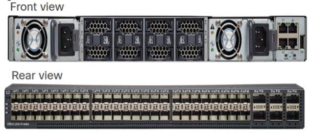
Cisco UCS 6454 Fabric Interconnect
For more information, see https://www.cisco.com/c/en/us/products/collateral/servers-unified-computing/datasheet-c78-741116.html.
Cisco UCS 5108 Blade Server Chassis
The Cisco UCS 5100 Blade Server Chassis is a crucial building block of Cisco UCS, delivering a scalable and flexible blade server chassis. The Cisco UCS 5108 Blade Server Chassis is 6RU high and can mount in an industry-standard 19-inch rack. A single chassis can house up to eight half-width Cisco UCS B-Series Blade Servers and can accommodate both half-width and full-width blade form factors. Four single-phase, hot-swappable power supplies are accessible from the front of the chassis. These power supplies are 92 percent efficient and can be configured to support nonredundant, N+ 1 redundant, and grid-redundant configurations. The rear of the chassis contains eight hot-swappable fans, four power connectors (one per power supply), and two I/O bays for Cisco UCS 2408 Fabric Extenders. A passive midplane provides connectivity between blade servers and fabric interconnects.
For more information, see http://www.cisco.com/c/en/us/products/servers-unified-computing/ucs-5100-series-blade-server-chassis/index.html.
The Cisco UCS 2408 Fabric Extender (Figure 3) brings the unified fabric into the blade server enclosure, providing connectivity between the blade servers and the fabric interconnect, simplifying diagnostics, cabling, and management. It is a fourth-generation I/O module (IOM) that shares the same form factor as the third-generation Cisco UCS 2304 Fabric Extender, which is compatible with the Cisco UCS 5108 Blade Server Chassis. The Cisco UCS 2408 connects the I/O fabric between the Cisco UCS 6454 Fabric Interconnect and the Cisco UCS 5100 Blade Server Chassis, enabling a lossless and deterministic converged fabric to connect all blades and chassis together. The fabric extender is similar to a distributed line card and does not perform any switching and is managed as an extension of the fabric interconnects. This approach removes switching from the chassis, reducing overall infrastructure complexity, and enabling Cisco UCS to scale to many chassis without multiplying the number of switches needed, reducing TCO, and allowing all chassis to be managed as a single, highly available management domain.
The Cisco UCS 2408 Fabric Extender has eight 25-Gigabit Ethernet, FCoE-capable, Small Form-Factor Pluggable 28 (SFP28) ports that connect the blade chassis to the fabric interconnect. Each Cisco UCS 2408 provides 10 Gigabit Ethernet ports connected through the midplane to each half-width slot in the chassis, providing a total of thirty-two 10 Gigabit Ethernet interfaces to Cisco UCS blade servers. Typically configured in pairs for redundancy, two fabric extenders provide up to 400 Gbps of I/O from Cisco UCS 6400 Series Fabric Interconnects to the Cisco UCS 5108 chassis.
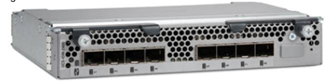
Cisco UCS 2408 Fabric Extender
For more information, see https://www.cisco.com/c/en/us/products/collateral/servers-unified-computing/datasheet-c78-742624.html.
Cisco UCS B200 M6 Blade Server
The Cisco UCS B200 M6 Blade Server (Figure 4) delivers performance, flexibility, and optimization for deployments in data centers, in the cloud, and at remote sites. This enterprise-class server offers market-leading performance, versatility, and density without compromise for workloads including virtual desktop infrastructure (VDI), web infrastructure, distributed databases, converged infrastructure, and enterprise applications such as Oracle and SAP HANA. The Cisco UCS B200 M6 Blade Server can quickly deploy stateless physical and virtual workloads through programmable, easy-to-use Cisco UCS Manager software and simplified server access through Cisco SingleConnect technology. The Cisco UCS B200 M6 Blade Server is a half-width blade with up to eight servers and can reside in the 6RU Cisco UCS 5108 Blade Server Chassis, offering one of the highest densities of servers per rack unit of blade chassis in the industry. You can configure the Cisco UCS B200 M6 to meet your local storage requirements without having to buy, power, and cool components that you do not need.
The Cisco UCS B200 M6 Blade Server provides these main features:
● Up to two 3rd Gen Intel Xeon Scalable CPUs with up to 40 cores per CPU
● 32 DIMM slots for industry-standard DDR4 memory at speeds up to 3200 MHz, with up to 8 TB of total memory when using 512-GB DIMMs
● Up to 16 DIMM slots ready for Intel Optane Data Center (DC) Persistent Memory (PMem) to accommodate up to 12 TB of Intel Optane DC PMem
● Modular LAN-on-motherboard (mLOM) card with Cisco UCS VIC 1440, a 2-port, 40 Gigabit Ethernet, FCoE-capable mLOM mezzanine adapter
● Optional rear mezzanine VIC with two 40-Gbps unified I/O ports or two sets of 4 x 10-Gbps unified I/O ports, delivering 80 Gbps to the server; adapts to either 10- or 40-Gbps fabric connections
● Two optional, hot-pluggable, solid-state disks (SSDs), or NVMe 2.5-inch drives with a choice of enterprise-class RAID or pass-through controllers or four M.2 SATA drives for flexible boot and local storage capabilities
● Support for one rear storage mezzanine card
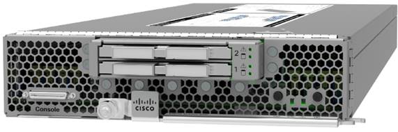
Cisco UCS B200 M6 Blade Server
For more information, see https://www.cisco.com/c/en/us/products/collateral/servers-unified-computing/ucs-b-series-blade-servers/datasheet-c78-2368888.html.
The Cisco UCS VIC1440 is a single-port 40-Gbps or 4 x 10-Gbps Ethernet and FCoE–capable mLOM designed for Cisco UCS B-Series Blade Servers. When used in combination with an optional port expander, Cisco UCS VIC 1440 capabilities are enabled for 40-Gbps Ethernet ports on each side of the fabric. The Cisco UCS VIC 1440 enables a policy-based, stateless, agile server infrastructure that can present to the host PCIe standards-compliant interfaces that can be dynamically configured as either NICs or HBAs.
For more information, see https://www.cisco.com/c/en/us/products/collateral/interfaces-modules/unified-computing-system-adapters/datasheet-c78-741130.html.
Cisco Nexus 9336C-FX2 Switches
In this solution, Cisco Nexus 9336C-FX2 Switches (Figure 5) are used as upstream switches. This solution offers thirty-six 40 and 100 Gigabit Ethernet Enhanced Quad SFP (QSFP+) ports. All ports are line rate, delivering 7.2 Tbps of throughput with a latency of less than 2 microseconds in a 1RU form factor.
Cisco Nexus 9336C-FX2 Switch
For more information, see https://www.cisco.com/c/en/us/products/switches/nexus-9336c-fx2-switch/index.html.
With the new A-Series All Flash FAS controller lineup, NetApp provides industry-leading performance while continuing to provide a full suite of enterprise-class data management and data protection features. The A-Series lineup offers double the number of I/O operations per second (IOPS), while decreasing latency.
This solution uses the NetApp AFF A800 (Figure 6). The AFF A800 is the top-of-the-line ONTAP all-flash storage array from NetApp, which at launch offered industry-first end-to-end NVMe and Fibre Channel over 32-Gbps Fibre Channel, as well as 100 Gigabit Ethernet connectivity. The A800 is designed for the workloads that demand the most performance (such as artificial intelligence [AI] and deep leaning). It also includes the robust set of enterprise data services for which ONTAP is known.
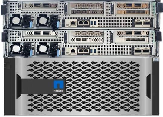
NetApp AFF A800
NetApp AFF A800 specifications
The major specifications of the NetApp A800 are listed here. For more information, see NetApp Hardware Universe.
● OS and data management
◦ NetApp ONTAP OS runs on the platform and manages the data, serving data to workloads running in the FlexPod environment.
● Maximum scale-out
◦ 2 to 24 nodes (12 high-availability pairs)
● Maximum SSDs
◦ 2880
● Maximum effective capacity
◦ 316.3 PB
● Raw capacity
◦ 2.5 PB effective capacity in a 4RU chassis
◦ Can cluster to mote than 70 PB, the most of any all-flash array (AFA)
● Performance
◦ Latency below 200 microseconds
◦ Throughput of 300 GBps
◦ 11.4 million IOPS
● RAID and data protection
◦ SnapMirroring and self-encrypting SSDs that are AES-256 and FIPS 140-2 compliant
◦ Full range of backup and data protection tools from NetApp that integrate well with its arrays
● Storage-saving features
◦ Deduplication and inline compression
● Data management
◦ Federation through NetApp A800 use of clustered nodes
◦ Unified storage infrastructure supporting both SAN and NAS protocols
◦ Movement of workloads between storage tiers
◦ Support for Amazon Web Services (AWS), Google Cloud Storage, IBM Cloud object storage, Microsoft Azure, and any OpenStack cloud service provider
◦ 100 Gigabit Ethernet NetApp MetroCluster
● Storage networking support
◦ NVMe and Fibre Channel, Fibre Channel, iSCSI, NFS, Parallel NFS (pNFS), Common Internet File System (CIFS) and Server Message Block (SMB), and Amazon Simple Storage Service (S3)
● NVMe
◦ End-to-end NVMe and Fibre Channel host–to–flash array connection over 32-Gbps Fibre Channel
● OS version
◦ NetApp ONTAP 9.4 RC1 or later
● Shelves and media
◦ NetApp NS224 (2RU, 24 drives, 2.5-inch SFF NVMe), DS224C (2RU, 24 drives, 2.5-inch SFF), and DS2246 (2RU, 24 drives, 2.5-inch SFF)
● Host and client OSs supported
◦ Microsoft Windows 2000, Windows Server 2003, Windows Server 2008, Windows Server 2012, and Windows Server 2016; Linux; Oracle Solaris; AIX; HP-UX; MacOS; and VMware
NetApp ONTAP 9.8 is the industry-leading flagship data-management software from NetApp that enables you to seamlessly manage and protect your data wherever it is located, whether on-premises, at the edge, or in the cloud.
ONTAP implementations can run on NetApp-engineered FAS or AFF appliances, on commodity hardware (ONTAP Select), and in private, public, or hybrid clouds (NetApp Private Storage and Cloud Volumes ONTAP). Specialized implementations offer best-in-class converged infrastructure as featured here as part of the FlexPod Datacenter solution and access to third-party storage arrays (NetApp FlexArray virtualization).
Together these implementations form the basic framework of the NetApp data fabric, with a common software-defined approach to data management and fast, efficient replication across platforms. FlexPod and ONTAP architectures can serve as the foundation for both hybrid cloud and private cloud designs.
The following sections provide an overview of ONTAP 9.8 as an industry-leading data management software designed on the principles of software-defined storage.
ONTAP 9.8 can run on multiple types of all-flash or FAS systems (with hybrid disks or spinning disks for storage) and form a storage cluster. ONTAP 9.8 can also manage the storage tier in the cloud. The use of a single ONTAP OS instance to manage different storage tiers makes efficient data tiering and workload optimization possible through a single management realm.
NetApp storage virtual machine
A NetApp ONTAP cluster serves data through at least one and possibly multiple storage virtual machines (SVMs; formerly called Vservers). An SVM is a logical abstraction that represents the set of physical resources of the cluster. Data volumes and network logical interfaces (LIFs) are created and assigned to an SVM and can reside on any node in the cluster to which the SVM has been given access. An SVM can own resources on multiple nodes concurrently, and those resources can be moved nondisruptively from one node in the storage cluster to another. For example, a NetApp FlexVol flexible volume can be nondisruptively moved to a new node and aggregate, or a data LIF can be transparently reassigned to a different physical network port. The SVM abstracts the cluster hardware and thus it is not tied to any specific physical hardware.
An SVM can support multiple data protocols concurrently. Volumes within the SVM can be joined to form a single NAS namespace, which makes all SVM data available through a single share or mount point to NFS and CIFS clients. SVMs also support block-based protocols, and logical unit numbers (LUNs) can be created and exported by using iSCSI, Fibre Channel, or FCoE. Any or all of these data protocols can be configured for use within a given SVM. Storage administrators and management roles can also be associated with an SVM, which enables higher security and access control, particularly in environments with more than one SVM, when the storage is configured to provide services to different groups or sets of workloads.
Storage efficiency has always been a primary architectural design point of ONTAP data management software. A wide variety of features allows you to store more data using less space. In addition to deduplication and compression, you can store your data more efficiently by using features such as unified storage, multitenancy, thin provisioning, and NetApp Snapshot technology.
Starting with ONTAP 9, NetApp guarantees that the use of NetApp storage efficiency technologies on AFF systems reduces the total logical capacity used to store customer data by 75 percent, a data reduction ratio of 4:1.
This space reduction is enabled by a combination of several technologies, including deduplication, compression, and compaction.
Data security continues to be an important consideration for customers purchasing storage systems. NetApp supported self-encrypting drives in storage clusters prior to ONTAP 9. However, in ONTAP 9, the encryption capabilities of ONTAP are extended by adding an onboard key manager (OKM). The OKM generates and stores keys for each of the drives in ONTAP, allowing ONTAP to provide all functions required for encryption out of the box. Through this capability, sensitive data stored on disk is secure and can be accessed only by ONTAP.
Beginning with ONTAP 9.1, NetApp has extended the encryption capabilities further with NetApp Volume Encryption (NVE), a software-based mechanism for encrypting data. It allows a user to encrypt data at the per-volume level instead of requiring encryption of all data in the cluster, thereby providing more flexibility and granularity to ONTAP administrators. This encryption extends to snapshot copies and NetApp FlexClone volumes that are created in the cluster. One benefit of NVE is that it runs after the implementation of the storage efficiency features, and, therefore, it does not interfere with the ability of ONTAP to create space savings.
For more information about encryption in ONTAP, see the NetApp Power Encryption Guide in the NetApp ONTAP 9 Documentation Center.
NetApp FlexClone technology enables instantaneous cloning of a data set without consuming any additional storage until cloned data differs from the original.
NetApp SnapMirror (data replication)
NetApp SnapMirror is a replication technology for data replication across different sites, or within the same data center, or in the on-premises data center to the cloud, or in the cloud to the on-premises data center.
ONTAP allows users to set minimum, maximum, and adaptive QoS for workloads:
● QoS Max (also known as limits): This setting is the maximum performance level assigned to the storage object. This setting limits the amount of system resources that the workload can use. It is often used to stop a workload from affecting other workloads. Max QoS can be set for the SVM, volume, LUN, or file in ONTAP. It works by throttling throughput or IOPS at the network side.
● QoS Min (also known as floors): This setting is the minimum "guaranteed" performance level assigned to the storage object. Min QoS can be set for the volume or LUN in ONTAP.
● Adaptive QoS: This dynamic QoS policy maintains the IOPS per terabyte ratio as storage size (used or provisioned) changes. Adaptive QoS policy lets performance (IOPS) scale automatically with storage capacity (TB). Adaptive QoS can be set for the volume.
● Service-level management: Service-level management is the management and monitoring of storage resources with respect to performance and capacity.
● Service-level objective (SLO): This setting defines the key tenets of service-level management. SLOs are defined by a service-level agreement (SLA) in terms of performance and capacity.
SnapCenter is NetApp next-generation data protection software for tier-1 enterprise applications. SnapCenter, with its single-pane management interface, automates and simplifies the manual, complex, and time-consuming processes associated with the backup, recovery, and cloning of multiple databases and other application workloads.
SnapCenter uses technologies, including NetApp Snapshot copies, SnapMirror replication technology, SnapRestore data recovery software, and FlexClone thin-cloning technology, that allow it to integrate seamlessly with technologies offered by Oracle, Microsoft, SAP, VMware, and MongoDB across Fibre Channel, iSCSI, and NAS protocols. This integration allows IT organizations to scale their storage infrastructure, meet increasingly stringent SLA commitments, and improve the productivity of administrators across the enterprise.
SnapCenter is used in this solution for the following use cases:
● Backup and restoration of VMware virtual machines
● Backup, restoration, protection, and cloning of SQL Server databases
● Storage provisioning for SQL Server databases and logs
NetApp SnapCenter architecture
SnapCenter is a centrally managed web-based application that runs on a Windows platform and remotely manages multiple servers that must be protected.
Figure 7 illustrates the high-level architecture of the NetApp SnapCenter Server.
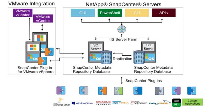
NetApp SnapCenter architecture
The SnapCenter Server has an HTML5-based GUI as well as PowerShell cmdlets and APIs.
The SnapCenter Server is high-availability capable out of the box, meaning that if one SnapCenter host is ever unavailable for any reason, then the second SnapCenter Server can seamlessly take over and no operations are affected.
The SnapCenter Server can push out plug-ins to remote hosts. These plug-ins are used to interact with an application, a database, or a file system. In most cases, the plug-ins must be present on the remote host so that application- or database-level commands can be issued from the same host on which the application or database is running.
To manage the plug-ins and the interaction between the SnapCenter Server and the plug-in host, SnapCenter uses SM Service, which is a NetApp SnapManager web service running on top of Windows Server Internet Information Services (IIS) on the SnapCenter Server. SM Service handles all client requests such as backup, restore, clone, and so on.
The SnapCenter Server communicates those requests to SMCore, which is a service that runs co-located within the SnapCenter Server and remote servers and plays a significant role in coordinating with the SnapCenter plug-ins package for Windows. The package includes the SnapCenter plug-in for Microsoft Windows Server and SnapCenter plug-in for Microsoft SQL Server to discover the host file system, gather database metadata, quiesce and thaw, and manage the SQL Server database during backup, restore, clone, and verification processes.
SnapCenter Virtualization (SCV) is another plug-in that manages virtual servers running on VMware and helps in discovering the host file system, databases on virtual machine disks (VMDK), and raw device mapping (RDM).
SnapCenter enables you to create application-consistent snapshot copies and to complete data protection operations, including snapshot copy-based backup, clone, restore, and backup verification operations. SnapCenter provides a centralized management environment, while using role-based access control (RBAC) to delegate data protection and management capabilities to individual application users across the SnapCenter Server and Windows hosts.
SnapCenter includes the following main features:
● A unified and scalable platform across applications and database environments and virtual and nonvirtual storage, powered by the SnapCenter Server
● RBAC for security and centralized role delegation
● Consistency of features and procedures across plug-ins and environments, supported by the SnapCenter user interface
● Snapshot-based application-consistent backup, restore, clone, protection, and backup verification support from both primary and secondary destinations (NetApp SnapMirror and SnapVault)
● A dedicated SnapCenter repository for the backup catalog and for faster data retrieval
● Remote package installation from the SnapCenter GUI
● Nondisruptive, remote upgrades
● Load balancing implemented by using Microsoft Windows network load balancing (NLB) and application request routing (ARR), with support for horizontal scaling
● Centralized scheduling and policy management to support backup and clone operations
● Centralized reporting, monitoring, and dashboard views
● Backup, restore, and data protection operations for VMware virtual machines, SQL Server databases, Oracle Databases, MySQL, SAP HANA, MongoDB, and Microsoft Exchange
● SnapCenter plug-in for VMware in vCenter integration into the vSphere Web Client; all virtual machine backup and restore tasks are preformed through the web client GUI
Using the SnapCenter plug-in for SQL Server, you can do the following:
● Create policies, resource groups, and backup schedules for SQL Server databases.
● Back up SQL Server databases and logs.
● Restore SQL Server databases (on Windows guest OS).
● Create database clones.
● Provision storage to Windows virtual machines for SQL Server databases and logs.
● Protect database backup on a secondary site for disaster recovery and on SnapVault for archival purposes.
● Monitor backup and data protection operations.
● Generate reports of backup and data protection operations.
● Generate dashboards and reports that provide visibility into protected versus unprotected databases and the status of backup, restore, and mount jobs.
Using the SnapCenter plug-in for VMware in vCenter, you can do the following:
● Create policies, resource groups, and backup schedules for virtual machines.
● Back up virtual machines, VMDKs, and datastores.
● Restore virtual machines, VMDKs, and files and folders (on the Windows guest OS).
● Monitor and report data protection operations on virtual machines and datastores.
● Restore an efficient storage base from primary and secondary snapshot copies through single-file SnapRestore.
● Attach and detach VMDKs.
● Support RBAC security and centralized role delegation.
● Provide guest file or folder (single or multiple) support for the Windows guest OS.
● Generate dashboards and reports that provide visibility into protected versus unprotected virtual machines and the status of backup, restore, and mount jobs.
● Attach virtual disks to an alternative virtual machine.
● Attach or detach virtual disks from secondary snapshot copies.
Microsoft SQL Server database storage layout with NetApp SnapCenter
SnapCenter best-practices for Microsoft SQL Server database layout are aligned with the suggested Microsoft SQL Server deployment. SnapCenter supports backup only of user databases that reside on a NetApp storage system. Along with the performance benefit of segregating the user database layout into different volumes, SnapCenter also has a large influence on the time required for backup and restore operations. The use of separate volumes for data files and log files significantly improves the restore time as compared to the use of a single volume hosting multiple user data files. Similarly, user databases with I/O-intensive applications may experience increased backup time.
When backing up databases with SnapCenter, take the following considerations into account:
● Databases with I/O-intensive queries throughout the day should be isolated in different volumes and eventually have separate jobs to back them up.
● Large databases and databases that have minimal restore-time objectives (RTOs) should be placed in separate volumes for faster recovery.
● Small to medium-size databases that are less critical or that have fewer I/O requirements should be consolidated into a single volume. By backing up many databases residing in the same volume, fewer snapshot copies need to be maintained. NetApp also recommends consolidating Microsoft SQL Server instances to use the same volumes to control the number of backup snapshot copies needed.
● Create separate LUNs to store full text-related files and file-streaming-related files.
● Assign a separate LUN for each instance to store Microsoft SQL Server log backups. The LUNs can be part of the same volume.
● System databases store database server metadata, configurations, and job details; they are not updated frequently. System databases and temporary database (tempdb) files should be placed in separate drives or LUNs. Do not place system databases in the same volume as user databases. User databases have different backup policies, and the frequency of user database backups is not same as for system databases.
The following are NetApp recommendations for volume design for optimal performance:
● Allocate at least 10 percent of available free space in an aggregate.
● Use flexible volumes to store Microsoft SQL Server database files and do not share volumes between hosts.
● Use New Technology File System (NTFS) mount points instead of drive letters to avoid the 26-drive letter limitation in Microsoft Windows Server.
● Configure a volume autosize policy, when appropriate, to help prevent out-of-space conditions.
● Set the snapshot copy reserve value in the volume to zero for ease of monitoring from an operational perspective.
● Disable storage snapshot copy schedules and retention policies. Instead, use the SnapCenter for SQL Server plug-in to coordinate snapshot copies of the Microsoft SQL Server data volumes.
● When the SQL Server database I/O profile consists mostly of large sequential read operations, such as with decision-support system workloads, enable read reallocation on the volume. Read reallocation optimizes the blocks for better performance. Place user data files (.mdf) on separate volumes because they are random read/write workloads. It is common to create transaction log backups more frequently than database backups. For this reason, place transaction log files (.ldf) on a separate volume or VMDK from the data files so that independent backup schedules can be created for each. This separation also isolates the sequential write I/O of the log files from the random read/write I/O of data files and significantly improves Microsoft SQL Server performance.
vSphere ESXi 7.0 delivers the services essential for the modern hybrid cloud. It powers the computing environment for modern applications, AI and machine learning (ML), and business-critical applications. Applications can be deployed using any combination of virtual machines, containers, and Kubernetes. Multiple ESXi hosts running on Cisco UCS B200 M6 blades are used to form a VMware ESXi cluster. The ESXi cluster pools the computing, memory, and network resources from all the cluster nodes and provides a resilient platform for virtual machines running on the cluster. VMware ESXi cluster features, vSphere high availability, and Distributed Resources Scheduler (DRS) contribute to the capability of the vSphere cluster to withstand failures to distribute resources across ESXi hosts.
Windows Server 2019 is the latest OS platform release from Microsoft. Windows Server 2019 is an excellent platform for running SQL Server 2019 databases. It offers new features and enhancements related to security, patching, domains, clusters, storage, and support for various new hardware features, etc. It enables Windows Server to provide best-in-class performance and a highly scalable platform for deploying SQL Server databases.
Microsoft SQL Server 2019 is the latest relational database engine from Microsoft. It offers many new features and enhancements to the relational and analytical engines and is offered in both Linux and Windows versions. As the most widely adopted and deployed database platform over several years, it has experienced database sprawl, which can lead to underutilization of hardware resources and a larger data center footprint, higher power consumption, uncontrolled licensing, and difficulties in managing hundreds or thousands of SQL instances. To avoid SQL Server sprawl, IT departments are seeking consolidation of SQL Server databases as a solution.
You should use the Microsoft Assessment and Planning (MAP) toolkit when planning SQL Server database consolidation or migration. The MAP toolkit scans existing infrastructure and finds the complete inventory of SQL Server installations in the network. Read the Microsoft Developer Network article here for additional information about the MAP toolkit for SQL Server databases.
The Cisco Intersight platform is a SaaS hybrid cloud operations solution that delivers intelligent automation, observability, and optimization to customers for traditional and cloud-native applications and infrastructure. It supports Cisco UCS and Cisco HyperFlex™ hyperconverged infrastructure, other Cisco devices connected to Cisco Intersight, third-party devices connected to Cisco Intersight, cloud platforms and services, and other integration endpoints. Because it is a SaaS-delivered platform, Cisco Intersight functions increase and expand with weekly releases.
For Cisco infrastructure, the Cisco Intersight platform works in conjunction with Cisco UCS Manager, Cisco Integrated Management Controller (IMC), and Cisco HyperFlex Connect. In addition, Cisco Intersight integrates with third-party storage, cloud services, virtualization, and container platforms. You can simply associate a model-based configuration to provision servers and associated storage and fabric automatically, regardless of form factor. Using profiles, IT staff can consistently align policy, server personality, and workloads. These policies can be created once and used to simplify server deployments, resulting in improved productivity and compliance and lower risk of failure due to inconsistent configuration. In addition, Cisco provides integrations to third-party operations tools, starting with ServiceNow, to allow customers to use their existing solutions more efficiently.
For more information about the Cisco Intersight platform, see https://www.cisco.com/c/en/us/products/cloud-systems-management/intersight/index.html.
FlexPod is a defined set of hardware and software that serves as an integrated foundation for both virtualized and nonvirtualized solutions. VMware vSphere built on FlexPod includes NetApp All Flash FAS storage, Cisco Nexus networking, Cisco Unified Computing System, and VMware vSphere software in a single package. The design is flexible enough that the networking, computing, and storage resources can fit in one data center rack or be deployed according to a customer's data center design. Port density enables the networking components to accommodate multiple configurations of this kind.
One benefit of the FlexPod architecture is the capability to customize, or "flex," the environment to suit a customer's requirements. A FlexPod system can easily be scaled as requirements and demands change. The unit can be scaled both up (adding resources to a FlexPod unit) and out (adding more FlexPod units). The reference architecture detailed in this document highlights the resiliency, cost benefit, and ease of deployment of an IP-based storage solution. A storage system capable of serving multiple protocols across a single interface allows customer choice and investment protection because it truly is a wire-once architecture.
Figure 8 shows FlexPod components and the network connections for a configuration with Cisco UCS 6454 Fabric Interconnects. This design can support 100-Gbps Ethernet connections between the fabric interconnect and NetApp AFF 800 storage array. Between the Cisco UCS 5108 Blade Server Chassis and the Cisco UCS fabric interconnect, up to eight 25-Gbps uplink cables can be connected using a Cisco UCS 2408 I/O module on each side of the fabric, thereby supporting up to 200 Gbps of network bandwidth on each side of the fabric. This infrastructure is deployed to provide iSCSI-booted hosts with file-level and block-level access to shared storage. The reference architecture reinforces the wire-once strategy, because as more storage is added to the architecture, no recabling is required from the hosts to the Cisco UCS fabric interconnect.
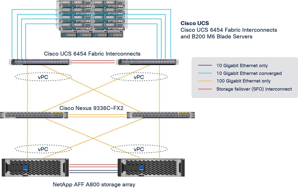
FlexPod with Cisco UCS 6454 Fabric Interconnects and Cisco UCS B200 M6 Blade Servers
Figure 8 shows a base design. Each of the components can be scaled easily to support specific business requirements. For example, more (or different) servers or blade chassis can be deployed to increase computing capacity, additional storage controllers or disk shelves can be deployed to improve I/O capability and throughput, and special hardware or software features can be added to introduce new features.
The following components were used to validate and test the solution:
● One Cisco UCS 5108 Blade Server Chassis with Cisco UCS 2408 I/O modules
● Four Cisco UCS B200 M6 Blade Servers with the Cisco UCS VIC 1440 and a port expander card
● Two Cisco Nexus 9336C-FX2 Switches
● Two Cisco UCS 6454 Fabric Interconnects
● One NetApp AFF A800 (high-availability pair) running clustered NetApp ONTAP with NVMe disk shelves and SSDs
In this solution, the VMware ESXi 7.0 virtual environment was tested and validated for deployment of Microsoft SQL Server 2019 databases on virtual machines running a Microsoft Windows Server 2019 guest operating system. SQL Server virtual machines are configured to connect the NetApp AFF A800 storage LUNs directly using the in-guest Microsoft software iSCSI initiator. This approach bypasses the ESXI hypervisor VMFS storage layer for the LUNs that are used for storing SQL Server database files. This design approach provides better performance, simplifies management, enables efficient backup of data, and allows the association of storage QoS directly to objects hosting SQL Server data.
Table 1 lists the hardware and software components and the image versions used in the solution.
Table 1. Hardware and software components
| Layer |
Device |
Image |
Comments |
| Computing |
● Fourth-generation Cisco UCS 6454 Fabric Interconnects
● 1 Cisco UCS 5108 Blade Server Chassis with 2 Cisco UCS 2408 I/O modules
● 4 Cisco UCS B200 M6 blades, each with one Cisco UCS VIC 1440 adapter and port expander card
|
Release 4.2(1d) |
|
| CPU |
2 Intel Xeon Gold 6330 CPUs, at 2.0 GHz, with 42-MB Layer 3 cache and 28 cores per CPU |
|
|
| Memory |
1024 GB (16 x 6-GB DIMMS operating at 3200 MHz) |
|
|
| Network |
2 Cisco Nexus 9336C-FX2 Switches |
Cisco NX-OS Release 9.3(7) |
|
| Storage |
2 NetApp AFF A800 storage controllers with 24 x 1.8-TB NVMe SSDs |
NetApp ONTAP Release 9.8 |
|
| Hypervisor |
VMware vSphere 7.0 |
Release 7.0.2, Build 17867351 |
|
|
|
Cisco UCS VIC Ethernet NIC (enic) driver |
Release 1.0.35.0-1OEM.670.0.0.8169922 |
|
| Operating system |
Microsoft Windows Server 2019 |
|
For virtual machine guest operating system |
| Database |
Microsoft SQL Server 2019 |
|
|
| NetApp SnapCenter |
NetApp SnapCenter |
Release 4.5 |
For virtual machine and SQL database data protection (backup, restore, clone, etc.) |
| Storage monitoring |
NetApp Active IQ Unified Manager |
Release 9.8P1 |
For monitoring storage infrastructure health and performance |
| Storage provisioning |
NetApp ONTAP tools for VMware vSphere |
Release 9.8 |
For datastore storage provisioning to ESXi hosts |
This section describes specific configurations and recommendations for deploying FlexPod Datacenter to host Windows Server 2019 virtual machines running SQL Server 2019 databases.
Note: This documentation does not list all the steps for deploying FlexPod Datacenter. Refer to the base infrastructure Cisco Validated Design documentation here: FlexPod Datacenter with VMware vSphere 7.0. Microsoft SQL Server 2019 deployment and configuration steps not explained in the infrastructure validated design are presented in the following sections.
This section discusses specific Cisco UCS Manager policies that are different from the base FlexPod infrastructure configuration and that are important for obtaining optimal performance for SQL Server workloads.
As mentioned earlier, SQL Server virtual machines are configured to access the storage volumes directly using the iSCSI protocol to store database files. Therefore, be sure to use the right network and adapter policies for low latency and better storage bandwidth because the underlying Cisco VIC network bandwidth is shared by many SQL Server virtual machines (for both management and storage access) as well as by ESXi host management, VMware vMotion and NFS traffic, and so on.
Virtual network interface card templates
The following virtual network interface card (vNIC) templates are used on each ESXi host for various infrastructure and SQL Server virtual machine management traffic. The purpose of each vNIC template is listed here:
● vSwitch0-A: Used for ESXi host management traffic over Fabric A
● vSwitch0-B: Used for ESXi host management traffic over Fabric B
● vDS0-A: Used for infrastructure management traffic such as vMotion, NFS storage access (optional), and SQL Server virtual machine management and for SQL Server iSCSI storage traffic over Fabric A
● vDS0-B: Used for infrastructure management traffic such as vMotion, NFS storage access (optional), and SQL Server virtual machine management and for SQL Server iSCSI storage traffic over Fabric B
● SQL-iSCSI-A: Used for booting the ESXi host from the NetApp storage LUN using the overlay network over Fabric A
● SQL-iSCSI-B: Used for booting the ESXi host from the NetApp storage LUN using the overlay network over Fabric B
Note: The NFS storage network traffic is generated by the guest operating systems (C:\ drives), which typically need less bandwidth. This traffic can be configured either on the vSwitch0-A or B or vDS-A or B interfaces. In this reference architecture, this traffic is configured on the vSwitch0-A and B vNICs.
Table 2 lists additional configuration details for the vNIC templates used in this reference architecture.
Table 2. vNIC templates and configuration details
| vNIC template |
vSwitch0-A |
vSwitch1-B |
vDS0-A |
vDS0-B |
SQL-iSCSI-A |
SQL-iSCSI-B |
||||
| Purpose |
ESXi host management and NFS storage access over Fabric Interconnect A |
ESXi host management and NFS storage access over Fabric Interconnect B |
SQL Server management, SQL Server iSCSI, vMotion, and NFS over Fabric A |
SQL Server management, SQL Server, vMotion, and NFS over Fabric B |
ESXi host SAN boot over Fabric A |
ESXi host SAN boot over Fabric B |
||||
| Setting |
Value |
Value |
Value |
Value |
Value |
Value |
||||
| Fabric ID |
A |
B |
A |
B |
A |
B |
||||
| Fabric failover |
Disabled |
Disabled |
Disabled |
Disabled |
Disabled |
Disabled |
||||
| Redundancy type |
Primary template (peer redundancy: vSwitch0-B) |
Secondary template (peer redundancy: vSwitch0-A) |
Primary template (peer redundancy: vDS0-B) |
Secondary template (peer redundancy: vDS0-A) |
No redundancy |
No redundancy |
||||
| Target |
Adapter |
Adapter |
Adapter |
Adapter |
Adapter |
Adapter |
||||
| Type |
Updating template |
Updating template |
Updating template |
Updating template |
Updating template |
Updating template |
||||
| Maximum transmission unit (MTU) |
9000 |
9000 |
9000 |
9000 |
9000 |
9000 |
||||
| MAC address pool |
MAC-POOL-A |
MAC-POOL-B |
MAC-POOL-A |
MAC-POOL-B |
MAC-POOL-A |
MAC-POOL-B |
||||
| QoS policy |
Not-Set |
Not-Set |
Not-Set |
Not-Set |
Not-Set |
Not-Set |
||||
| Network control policy |
Enabled-CDP-LLDP |
Enabled-CDP-LLDP |
Enabled-CDP-LLDP |
Enabled-CDP-LLDP |
Enabled-CDP-LLDP |
Enabled-CDP-LLDP |
||||
| Connection policy: Virtual machine queue (VMQ) |
Not-Set |
Not-Set |
SQL-VMQ |
SQL-VMQ |
Not-Set |
Not-Set |
||||
| VLANs |
IB-Mgmt (113), SQL-NFS (3051), and Native-VLAN (2) |
IB-Mgmt (113), SQL-NFS (3051), and Native-VLAN (2) |
SQL-iSCSI-A (3011), SQL-iSCSI-B (3021), SQL-Mgmt (901), vMotion (3000), and Native-VLAN (2) |
SQL-iSCSI-A (3011), SQL-iSCSI-B (3021), SQL-Mgmt (901), vMotion (3000), and Native-VLAN (2) |
SQL-iSCSI-A (3011) and Native-VLAN (2) |
SQL-iSCSI-A (3021) and Native-VLAN (2) |
||||
| Native VLAN |
Native-VLAN (2) |
Native-VLAN (2) |
Native-VLAN (2) |
Native-VLAN (2) |
SQL-iSCSI-A (3011) |
SQL-iSCSI-B (3021) |
||||
| vNICS derived and adapter policy used for vNICs |
vNICs: 00-vSwitch-A and 01-vSwitch-B Adapter policy: VMware |
vNICs: 02-vDS0-A and 03-vDS0-B Adapter policy: VMware-HighTrf |
vNICs: 04-iSCSI-A Adapter policy: VMware |
vNICs: 05-iSCSI-B Adapter policy: VMware |
||||||
Note: Verify that the ports on the upstream switches and NetApp storage interfaces are appropriately configured with the MTU and VLANs for end-to-end consistent configuration.
Table 3 lists additional information about the VLANs used for various purposes in the reference architecture.
Table 3. VLANs used for various traffic
| VLAN name |
VLAN purpose |
ID used in this architecture validation |
| In-band management |
VLAN for in-band management of ESXi hosts |
113 |
| Native-VLAN |
VLAN to which untagged frames are assigned |
2 |
| SQL-MGMT |
VLAN for in-band management of SQL Server virtual machines |
905 |
| SQL-Client (optional) |
VLAN for SQL Server client communication traffic or for other traffic coming into services running in the virtual machines |
1000 |
| SQL-iSCSI-A |
VLAN for iSCSI A traffic for SQL Server virtual machines on ESXi as well as ESXi Infrastructure |
3015 |
| SQL-iSCSI-B |
VLAN for iSCSI B traffic for SQL Server virtual machines on ESXi as well as ESXi Infrastructure |
3025 |
| vMotion |
VLAN for vMotion |
3000 |
| SQL-NFS |
VLAN for accessing NetApp storage LUNs using NFS protocol by ESXI hosts (used for storing virtual machine OS disks [.vmdk]) |
3055 |
| Out-of-band management |
VLAN for out-of-band management of Cisco UCS B200 M6 blades |
13 |
To help reduce the burden for the hypervisor and eliminate queue sharing, the Cisco UCS VIC can create dedicated queue pairs for guest machines running under ESXi. This approach provides significant benefits. First, the transmit and receive queue pairs are no longer shared with other guest machines. Second, the hypervisor is no longer responsible for sorting and switching packets because packet steering is moved to the adapter. The adapter performs packet steering based on Layer 2 information such as the MAC address and VLAN. As a result, the hypervisor is responsible only for moving the traffic between the adapter and the virtual machine. This approach improves I/O performance and frees the hypervisor for other tasks. The Cisco UCS VIC supports up to 128 virtual machine queues (VMQs) per vNIC and a total of 256 VMQs per adapter.
Create a VMQ policy with appropriate settings as shown in Figure 9. The number of VMQs is typically number of virtual machines in the host, and the number of interrupts will be 2 x VMQ + 2.
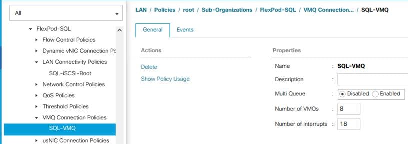
VMQ policy definition
The VMQ policy needs to be applied on the vDS0-A and vDS0-B vNIC templates. Figure 10 shows VMQ policy applied on the vDS0-A vNIC template.
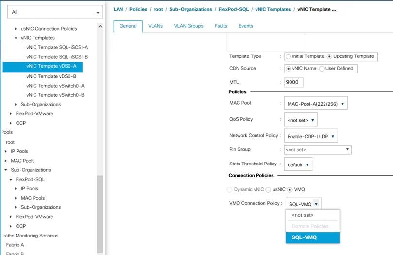
Applying VMQ policy to the vNIC template
The adapter policy allows the administrator to declare the capabilities of the vNIC, such as the number of rings, ring sizes, and offload enablement and disablement. The transmit queues and receive queues defined in the default VMware adapter policy may not be sufficient as more SQL Server databases are consolidated on the FlexPod system.
Note: You should increase the transmit and receive queues in smaller increments added with sufficient testing based on workload demand instead of setting them directly to the highest possible values. Changes to these settings need to be thoroughly tested before they are used in the production deployment. For more information about VIC tuning options and performance validation, refer to the following links:
As SQL Server guest virtual machine storage traffic flows through vNICs 02-vDS0-A and 03-vDS0-B, an adapter policy with higher receive and transmit queues is used. A predefined network adapter, VMware-HighTrf, has been used for vNICs 02-vDS0-A and 03-vDS0-B. For the rest of the vNICs, another predefined adapter policy, VMware, is used. Figure 11 shows a VMware-HighTrf adapter policy used for the FlexPod system built using ESXi clusters for running SQL Server database workloads.
Receive-side scaling (RSS) improves the performance by scheduling the interrupts on multiple cores on the host. Offloading networking functions such as checksum, segmentation, and so on from the host to the adapter reduces the host CPU requirements for processing these functions.
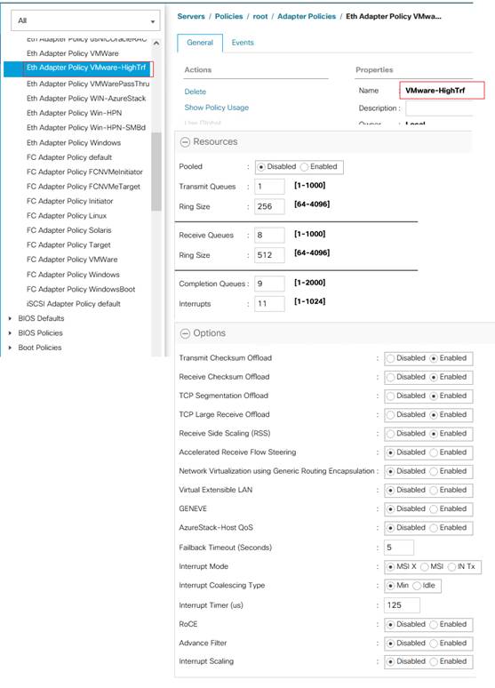
Adapter policy
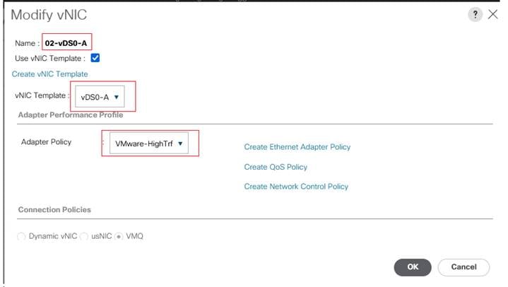
While deriving the vNICs from the templates using LAN connectivity policy, the adapter policy in Figure 11 is applied to vNICs used to serve SQL Server storage traffic. In this reference architecture, this adapter policy is applied to vNICs 02-vDS0-A and 03-vDS0-B, which are derived from vDS0-A and vDS0-B. For the rest of the vNICs, the predefined adapter policy VMware is used. Figure 12 shows the adapter policy VMware-HighTrf applied to the 02-vDS-A vNIC.
Applying adapter policy
By using vNIC templates as detailed in Table 2, a LAN connectivity policy is created, and within this policy six vNICs have been derived in the specific order as shown in Figure 13. Every ESXi server will detect the network interfaces in the same order, and the interfaces will always be connected to the same VLANs over the same network fabrics.
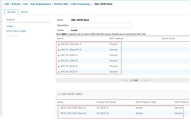
LAN connectivity policy
The two iSCSI vNICs (highlighted at the bottom of the figure) are overlay network adapters that are detected during the ESXi boot itself. They establish connections to the NetApp storage array and boot the Cisco UCS B200 M6 blade from the storage SAN LUN.
You should use appropriate BIOS settings on the servers based on the workload they run. The default BIOS settings promote power savings by reducing the operating speeds of processors and move the cores to deeper sleep states. These states need to be disabled for sustained high performance of database queries. Table 4 lists the BIOS settings used in the performance tests for obtaining optimal system performance for SQL Server online transaction processing (OLTP) workloads on Cisco UCS B200 M6 servers. The remaining settings are left at the default (Platform Default).
Table 4. BIOS settings
| Name |
Value |
| Adjacent Cache Line Prefetcher |
Enabled |
| Autonomous Core C-State |
Disabled |
| Boot Performance Mode |
Max Performance |
| CPU Hardware Power Management |
HWPM Native Mode |
| CPU Performance |
Enterprise |
| DCU IP Prefetcher |
Enabled |
| DCU Steamer Prefetch |
Enabled |
| DRAM Clock Throttling |
Performance |
| Energy Efficient Turbo |
Disabled |
| Entergy Performance |
Performance |
| Energy Performance Tuning |
OS |
| Enhanced Intel SpeedStep Tech |
Enabled |
| Frequency Floor Override |
Disabled |
| Hardware Prefetcher |
Enabled |
| IMC Interleave |
Auto |
| Intel Dynamic Speed Select |
Disabled |
| Intel Hyper Threading tech |
Enabled |
| Intel Virtualization Technology |
Enabled |
| LLC Prefetch |
Enabled |
| P-State Coordination |
HW All |
| Package C-State Limit |
C0 C1 State |
| Patrol Scrub |
Disabled |
| Power Technology |
Performance |
| Power C-State, Processor (C1E, C3, C6, and C7) Report |
Disabled |
| Panic and High Watermarks |
High |
| Processor EPP Enable |
Enabled |
| Process EPP Profile |
Performance |
| Sub NUMA Clustering |
Disabled |
| UPI Prefetch |
Enabled |
| UPI Link Frequency Select |
9.6 GTps |
| XPT Prefetch |
Enabled |
| LV DDR Mode (RAS Memory Tab) |
Performance mode |
| Memory Refresh Rate (RAS Memory Tab) |
1 x Refresh |
| LV DDR Mode (RAS Memory Tab) |
Performance |
| Partial Cache Line Sparing (RAM Memory Tab) |
Disable |
The remaining policies and configuration steps for deploying FlexPod to host SQL Server virtual machines are the same as in the base infrastructure Cisco Validated Design described here: FlexPod Datacenter with VMware vSphere 7.0 and NetApp ONTAP 9.7 - Cisco.
For iSCSI-specific Cisco UCS and VMware ESXi host configuration steps, refer to the “FlexPod iSCSI Addition” section in the infrastructure Cisco Validated Design described here: FlexPod Datacenter with VMware vSphere 7.0 and NetApp ONTAP 9.7 - Cisco.
NetApp storage configuration and management tools setup
This section provides detailed information about how to configure NetApp storage and management tools such as ONTAP tools and SnapCenter that are used and validated in this solution.
NetApp storage configuration for Microsoft Windows virtual machines on VMware ESXi and Microsoft SQL Server databases
On the NetApp storage cluster, storage virtual machines (SVMs) are created for ESXi datastores for Windows Server 2019 virtual machines and SQL Server databases and logs.
Create the SVM for the Microsoft SQL Server workload
The SVM for SQL Server databases serves as the logical storage system for Windows virtual machines and SQL Server databases, called the SQL SVM.
To create a SQL SVM, follow these steps:
1. Enter the vserver create command.
vserver create –vserver SQL-SVM –rootvolume sql_svm_rootvol –aggregate aggr1_node01 –rootvolume-security-style unix
2. Select the SVM data protocols to configure, keeping iSCSI and NFS only.
vserver remove-protocols –vserver SQL-SVM -protocols fcp,cifs,ndmp
3. Add the two data aggregates to the SQL SVM aggregate list for the NetApp ONTAP tools.
vserver modify –vserver SQL-SVM –aggr-list aggr1_node01,aggr1_node02
4. Enable and run the NFS protocol in the SQL SVM.
nfs create -vserver SQL-SVM -udp disabled
5. Turn on the SVM vStorage parameter for the NetApp NFS vStorage API Array Integration (VAAI) plug-in.
vserver nfs modify –vserver SQL-SVM –vstorage enabled
vserver nfs show
Create load-sharing mirrors of the SVM root volume
To create a load-sharing mirror of the SVM root volume, follow these steps:
1. Create a volume to be the load-sharing mirror of the infrastructure SVM root volume on each node.
volume create –vserver SQL-SVM –volume sql_rootvol_m01 –aggregate aggr1_node01 –size 1GB –type DP
volume create –vserver SQL-SVM –volume sql_rootvol_m02 –aggregate aggr1_node02 –size 1GB –type DP
2. Create a job schedule to update the root volume mirror relationships every 15 minutes.
job schedule interval create -name 15min -minutes 15
3. Create the mirroring relationship.
snapmirror create –source-path SQL-SVM:sql_svm_rootvol –destination-path SQL-SVM:sql_rootvol_m01 –type LS -schedule 15min
snapmirror create –source-path SQL-SVM:sql_svm_rootvol –destination-path SQL-SVM:sql_rootvol_m02 –type LS -schedule 15min
4. Initialize the mirroring relationship.
snapmirror initialize-ls-set –source-path SQL-SVM:sql_svm_rootvol
snapmirror show
5. Create the block protocol (iSCSI) service. Run the following command to create the iSCSI service on the SVM. This command also starts the iSCSI service and sets the iSCSI qualified name (IQN) for the SVM.
iscsi create -vserver SQL-SVM
iscsi show
To configure secure access to the storage controller, follow these steps:
1. Increase the privilege level to access the certificate commands.
set -privilege diag
Do you want to continue? {y|n}: y
2. Generally, a self-signed certificate is already in place. Verify the certificate and obtain parameters (for example, <serial-number>) by running the following command:
security certificate show
3. For each SVM shown, the certificate common name should match the Domain Name System (DNS) fully qualified domain name (FQDN) of the SVM. Delete the two default certificates and replace them with either self-signed certificates or certificates from a certificate authority (CA). To delete the default certificates, run the following commands:
security certificate delete -vserver SQL-SVM -common-name SQL-SVM -ca SQL-SVM -type server -serial <serial-number>
Note: Deleting expired certificates before creating new certificates is a best practice. Run the security certificate delete command to delete the expired certificates. In the following command, use tab completion to select and delete each default certificate.
4. To generate and install self-signed certificates, run the following commands as one-time commands. Generate a server certificate for the SQL SVM and the cluster SVM. Use tab completion to aid in the completion of these commands.
security certificate create -common-name <cert-common-name> -type server -size 2048 -country <cert-country> -state <cert-state> -locality <cert-locality> -organization <cert-org> -unit <cert-unit> -email-addr <cert-email> -expire-days <cert-days> -protocol SSL -hash-function SHA256 -vserver SQL-SVM
5. To obtain the values for the parameters required in step 6 (<cert-ca> and <cert-serial>), run the security certificate show command.
6. Enable each certificate that was just created by using the –server-enabled true and –client-enabled false parameters. Use tab completion to aid in the completion of these commands.
security ssl modify -vserver <clustername> -server-enabled true -client-enabled false -ca <cert-ca> -serial <cert-serial> -common-name <cert-common-name>
7. Revert to the normal admin privilege level and set up the system to allow SVM logs to be available on the web.
set –privilege admin
vserver services web modify –name spi|ontapi|compat –vserver * -enabled true
To configure NFS Version 3 (NFSv3) on the SQL SVM, follow these steps:
1. Create a new rule for the infrastructure NFS subnet in the default export policy.
vserver export-policy rule create –vserver SQL-SVM -policyname default –ruleindex 1 –protocol nfs -clientmatch <infra-nfs-subnet-cidr> -rorule sys –rwrule sys -superuser sys –allow-suid false
2. Assign the FlexPod export policy to the SQL SVM root volume.
volume modify –vserver SQL-SVM –volume sql_svm_rootvol –policy default
Storage configuration for Microsoft SQL Server databases
Application administrators need access to the SQL SVM to perform the following tasks:
● Provision storage for SQL Server databases.
● Back up, restore, clone, and protect SQL Server databases.
Create NetApp FlexVol volumes for Microsoft SQL Server database and logs
Create FlexVol volumes by running the following commands. The information required to create a NetApp FlexVol volume is as follows:
● Volume name
● Volume size
● Aggregate on which the volume exists
In this solution, we have distributed SQL Server data and log volumes on two aggregates equally, to balance performance and capacity utilization. For odd-numbered virtual machines, the data volumes reside on an aggregate tied to node-01, and for even-numbered virtual machines, the data volumes reside on the aggregate tied to node-02. Corresponding log volumes will be on the other controller or node. As you start the workload, make sure that you start with an even number of virtual machines, so that I/O will be evenly distributed.
Figure 14 shows a detailed storage layout scenario for the SQL Server database and logs.
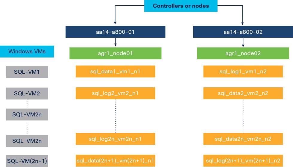
Storage layout for Microsoft SQL Server database and logs
To create the SQL Server database and log volumes, enter these commands:
volume create -vserver SQL-SVM -volume sql_data1_vm1_n1 -aggregate aggr1_node01 -size 300GB -state online -policy default -junction-path /sql_data1_vm1_n1 -space-guarantee none -percent-snapshot-space 0
volume create -vserver SQL-SVM -volume sql_data2_vm2_n2 -aggregate aggr1_node02 -size 300GB -state online -policy default -junction-path /sql_data2_vm2_n1 -space-guarantee none -percent-snapshot-space 0
volume create -vserver SQL-SVM -volume sql_log1_vm1_n2 -aggregate aggr1_node02 -size 250GB -state online -policy default -junction-path /sql_log1_vm1_n2 -space-guarantee none -percent-snapshot-space 0
volume create -vserver SQL-SVM -volume sql_log2_vm2_n1 -aggregate aggr1_node01 -size 250GB -state online -policy default -junction-path /sql_log2_vm2_n1 -space-guarantee none -percent-snapshot-space 0
snapmirror update-ls-set -source-path SQL-SVM:sql_svm_rootvol
Create Microsoft SQL Server database and log LUNs
To create SQL Server database and log LUNs, enter these commands:
lun create -vserver SQL-SVM -volume sql_data1_vm1_n1 -lun sql-db1-vm1 -size 250GB -ostype windows -space-reserve disabled
lun create -vserver SQL-SVM -volume sql_data2_vm2_n2 -lun sql-db2-vm2 -size 250GB -ostype windows -space-reserve disabled
lun create -vserver SQL-SVM -volume sql_log1_vm1_n2 -lun sql-log1-vm1 -size 200GB -ostype windows -space-reserve disabled
lun create -vserver SQL-SVM -volume sql_log2_vm2_n1 -lun sql-log2-vm2 -size 200GB -ostype windows -space-reserve disabled
Create iSCSI logical interfaces
To create iSCSI logical interfaces (LIFs), create four iSCSI LIFs (two on each node), by running the following commands:
network interface create -vserver SQL-SVM -lif sql-iscsi-lif01a -role data -data-protocol iscsi -home-node <aa14-a800-01> -home-port a0a-<SQL-VM-iSCSI-A-id> -address <sql-iscsi-lif01a_ip> -netmask <iscsi_lif_mask> –status-admin up –failover-policy disabled –firewall-policy data –auto-revert false
network interface create -vserver SQL-SVM -lif sql-iscsi-lif01b -role data -data-protocol iscsi -home-node <aa14-a800-01> -home-port a0a-<SQL-VM-iSCSI-B-id> -address <sql-iscsi-lif01b_ip> -netmask <iscsi_lif_mask > –status-admin up –failover-policy disabled –firewall-policy data –auto-revert false
network interface create -vserver SQL-SVM -lif sql-iscsi-lif02a -role data -data-protocol iscsi -home-node <aa14-a800-02> -home-port a0a-<SQL-VM-iSCSI-A-id> -address <sql-iscsi-lif02a_ip> -netmask <iscsi_lif_mask> –status-admin up –failover-policy disabled –firewall-policy data –auto-revert false
network interface create -vserver SQL-SVM -lif sql-iscsi-lif02b -role data -data-protocol iscsi -home-node <aa14-a800-02> -home-port a0a-<SQL-VM-iSCSI-B-id> -address <sql-iscsi-lif02b_ip> -netmask <iscsi_lif_mask > –status-admin up –failover-policy disabled –firewall-policy data –auto-revert false
network interface show
To create NFS LIFs, create two NFS LIFs (one on each node), by running following commands:
network interface create -vserver SQL-SVM -lif sql-nfs-lif01 -role data -data-protocol nfs -home-node <aa14-a800-01> -home-port a0a-<SQL-VM-NFS-id> -address <sql-nfs-lif01_ip> -netmask <nfs_lif_mask> –status-admin up –failover-policy disabled –firewall-policy data –auto-revert false
network interface create -vserver SQL-SVM -lif sql-nfs-lif02 -role data -data-protocol nfs -home-node <aa14-a800-02> -home-port a0a-<SQL-VM-NFS-id> -address <sql-nfs-lif02_ip> -netmask <nfs_lif_mask> –status-admin up –failover-policy disabled –firewall-policy data –auto-revert false
network interface show
To add the infrastructure SVM administrator and SVM administration LIF in the out-of-band management network, follow these steps:
1. Run the following commands:
network interface create -vserver SQL-SVM -lif SQL-SVM-mgmt -role data -data-protocol none -home-node <aa14-a800-01> -home-port a0a-<SQL-VM-MGMT-id> -address <SQL-SVM-Mgmt_ip> -netmask <SQL-SVM-Mgmt_mask> –status-admin up –failover-policy system-defined –firewall-policy mgmt –auto-revert true
Note: The SVM management IP address in this step should be in the same subnet as the storage cluster management IP address.
2. Create a default route to allow the SVM management interface to reach the outside world.
network route create –vserver SQL-SVM -destination 0.0.0.0/0 –gateway <svm-mgmt-gateway>
network route show
3. Set a password for the SVM vsadmin user and unlock the user.
security login password –username vsadmin –vserver SQL-SVM
Enter a new password: <password>
Enter it again: <password>
security login unlock –username vsadmin –vserver SQL-SVM
Note: A cluster serves data through at least one and possibly several SVMs. We have just created a single SVM. If you want to configure your environment with multiple SVMs, this is a good time to create additional SVMs.
Create storage volumes for Microsoft Windows virtual machines (VMware ESXi datastore)
The SVM for Windows Server 2019 virtual machines serves as a logical storage system for ESXi datastores, called the infrastructure SVM. The infrastructure SVM is managed by the infrastructure administrator, who is authorized to perform the following tasks:
● Provision storage for ESXi datastores.
● Back up and restore virtual machines.
To create storage volumes for Windows virtual machine datastores and virtual machine swap files, create FlexVols for the SQL virtual machine datastores and swap datastore by running the following commands:
volume create -vserver SQL-SVM -volume sql_vms_datastore -aggregate aggr1_node01 -size 800GB -state online -policy default -junction-path /sql_vms_datastore -space-guarantee none -percent-snapshot-space 0
volume create -vserver SQL-SVM -volume sql_vms_swap -aggregate aggr1_node01 -size 200GB -state online -policy default -junction-path /sql_vms_swap -space-guarantee none -percent-snapshot-space 0
On NetApp AFF systems, deduplication is enabled by default. To schedule deduplication, after the volumes are created, assign a once-a-day deduplication schedule to the volumes:
efficiency modify –vserver SQL-SVM –volume sql_data1_vm1_n1 –schedule sun-sat@0 efficiency modify –vserver SQL-SVM –volume sql_data2_vm2_n2 –schedule sun-sat@0 efficiency modify –vserver SQL-SVM –volume sql_vms_datastore –schedule sun-sat@0
After the Cisco UCS service profiles have been created, each infrastructure server in the environment will have a unique configuration. To proceed with the FlexPod deployment, specific information must be gathered from each Cisco UCS server and from the NetApp controllers. Insert the required information into Table 5.
Note: To obtain the iSCSI IQN, run the iscsi show command on the storage cluster management interface.
Table 5. iSCSI IQN, iSCSI LIFs, and NFS LIFs
| IQN or LIF IP address |
Information |
| SQL-SVM IQN |
|
| sql-iscsi-lif01a_ip |
|
| sql-iscsi-lif01b_ip |
|
| sql-iscsi-lif02a_ip |
|
| sql-iscsi-lif02b_ip |
|
| sql-nfs-lif01_ip |
|
| sql-nfs-lif02_ip |
|
NetApp ONTAP tools for VMware vSphere 9.8
Refer to the Deployment and Setup Guide for ONTAP Tools for VMware vSphere 9.8 for prerequisites and deployment steps for ONTAP tools.
NetApp ONTAP Release 9.8 tools were used in this solution validation to provision storage for VMware ESXi datastores for virtual machines.
NetApp SnapCenter 4.5 was used in this solution validation for the following use cases:
● Backup and restoration of VMware virtual machines
● Backup, restoration, protection, and cloning of SQL Server databases
● Storage provisioning for SQL Server databases and logs
Refer to the deployment guide for the SnapCenter plug-in for VMware vSphere for prerequisites and deployment steps for the SnapCenter plug-in for VMware vSphere 4.5. Installation and configuration of the SnapCenter plug-in for VMware vCenter is required for virtual machine backup and restore operations.
For more details, refer to the SnapCenter software documentation.
Install NetApp SnapCenter plug-in for Microsoft SQL Server
The SnapCenter plug-in for Microsoft SQL Server is required to protect SQL Server databases using SnapCenter. The SnapCenter plug-in for Microsoft SQL Server and SnapCenter plug-in for Microsoft Windows are both required on each Windows virtual machine running SQL Server.
Refer to the installation guide for the SnapCenter plug-in for Microsoft SQL Server for prerequisites and installation steps. When a host (Windows virtual machine) running SQL Server is added to SnapCenter, the SnapCenter plug-in for Microsoft SQL Server and the SnapCenter plug-in for Microsoft Windows are installed on the virtual machine. Table 6 summarizes the port requirements.
Table 6. Port requirements
| Port |
Requirement |
| 443 (HTTPS) |
This port is used for communication between the SnapCenter server and SVM management LIF of ONTAP. |
| 8146 (HTTPS) |
This port is used for communication between the SnapCenter client (the SnapCenter user) and the SnapCenter server. The port is also used for communication from the plug-in hosts to the SnapCenter server. |
| 135 and 445 (TCP) on Windows plug-in hosts |
The ports are used for communication between the SnapCenter server and the host on which the plug-in is installed. To push plug-in package binaries to Windows plug-in hosts, the ports must be open only on the plug-in host, and they can be closed after installation. |
| 8145 (HTTPS), bidirectional |
The port is used for communication between SMCore and the hosts on which the SnapCenter plug-ins package for Windows is installed. |
| 1433 (TCP) |
This port is used for SQL Server management access. |
License requirements for NetApp SnapCenter plug-in for Microsoft SQL Server
Table 7 lists the licenses that must be installed on the ONTAP storage system to back up and restore SQL Server databases.
Table 7. NetApp SnapCenter plug-in for Microsoft SQL Server license requirements
| Product |
License requirements |
| ONTAP primary destination |
For the SnapCenter plug-in for SQL Server, the following licenses should be installed:
● One of these: SnapMirror or SnapVault (for secondary data protection regardless of the type of relationship)
● SnapManagerSuite: Used for SnapCenter functions
● SnapRestore: Used for restore operations
● FlexClone: Used for mount and attach operations
|
| ONTAP secondary destinations |
To protect SQL databases on secondary storage:
● FlexClone: Used for mount and attach operations
|
NetApp Active IQ Unified Manager 9.8
NetApp Active IQ Unified Manager (AIQ UM) enables you to monitor and manage the health and performance of your ONTAP storage systems and virtual infrastructure from a single interface. Unified Manager provides a GUI that displays the capacity, availability, protection, and performance status of the monitored storage systems.
Refer to the Installation Guide for Active IQ Unified Manager 9.8 for prerequisites and configuration steps for AIQ UM 9.8.
This section describes some of the configuration recommendations specific to VMware ESXi that should be implemented to achieve optimal system performance for SQL Server workloads. For other tunings for SQL Server workloads, see https://www.vmware.com/content/dam/digitalmarketing/vmware/en/pdf/solutions/sql-server-on-vmware-best-practices-guide.pdf.
An ESXi host can take advantage of several power management features that the hardware provides to adjust the trade-off between performance and power use. You can control the way that ESXi uses these features by selecting a power management policy.
ESXi has been heavily tuned to promote high I/O throughput efficiently by using fewer CPU cycles and conserving power. Hence, the power mode on the ESXi host is set to Balanced. However, for critical database deployments, you should set the power mode to High Performance. Selecting High Performance causes the physical cores to run at a higher frequency, and thereby this setting will have a positive impact on database performance. Figure 15 shows the ESXi host power setting.
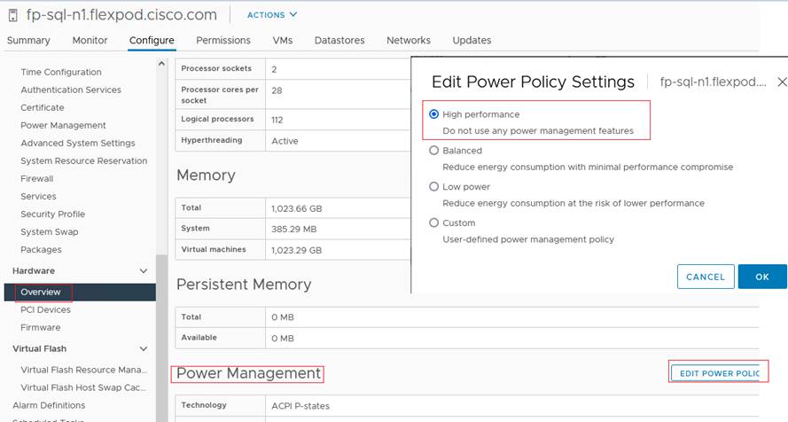
VMware ESXi host power policy
VMware ESXi host networking configuration
This section provides more information about ESXi host network configuration for the FlexPod system hosting SQL Server virtual machines. These specific network configuration changes are required to allow SQL Server guest virtual machines to directly access NetApp storage LUNs by passing the ESXi hypervisor intervention.
Note that the Cisco UCS LAN connectivity policy helps ensure that vNICs are presented to ESXi in the same order as they are derived in the LAN connectivity policy. Table 8 lists the order in which the vNICs will be mapped to the ESXi host physical adapters.
Table 8. Mapping of Cisco UCS Manager vNICs and VMware ESXi physical adapters
| vNIC name |
ESXi physical adapter and speed |
| 00-vSwitch0-A |
vmnic0, 40 Gbps |
| 01-vSwitch0-B |
vmnic1, 40 Gbps |
| 02-vDS0-A |
vmnic2, 40 Gbps |
| 03-vDS0-B |
vmnic3, 40 Gbps |
| 04-iSCSI-A |
vmnic4, 40 Gbps |
| 05-iSCSI-B |
vmnic5, 40 Gbps |
In this reference architecture, the infrastructure ESXi management VMkernel ports, the in-band management interfaces including the vCenter management interface, and the infrastructure NFS VMkernel ports are left on vSwitch0 to more easily bring back up the virtual environment in the event that it needs to be completely shut down. Other infrastructure network traffic, such as vMotion and SQL Server virtual machine management traffic, is migrated to the VMware vSphere Distributed Switch (vDS). SQL Server virtual machine iSCSI storage traffic is also configured on the vDS. The vMotion VMkernel ports are moved to the vDS to allow QoS marking of vMotion to be performed at the VLAN level in the vDS if vMotion needs to have QoS policies applied in the future.
The following sections provide more details about the network configuration.
VMware ESXi host management network and NFS storage access
A default standard virtual switch, vSwitch0, is created to manage the ESXi host management traffic. This switch is created using two physical network adapters, vmnic0 and vmnic1, in an active-active fashion. A default VMkernel adapter is assigned to this switch using the default Management Network port group.
A VMKernel port is also configured on vSwitch0 for NetApp storage access using the NFS file-sharing protocol. This NFS VMKernel is configured with MTU 9000 and tagged with a dedicated VLAN.
Table 9 lists details about vSwitch0 and the port groups.
Table 9. VMware vSphere standard switch vSwitch0 configuration and port group details
| Configuration |
Details |
| Switch name |
vSwitch0 |
| Number of physical adapters (uplinks) |
vmnic0 and vmnic1 |
| MTU setting |
9000 |
| Port groups created on this standard switch |
|
| Management network |
● Purpose: For ESXi host management
● Active uplinks: vmnic0 and vmnic1
● VLAN: 113
● A VMKernel port (vmk0) is configured with an appropriate IP address on each ESXi host.
● MTU on vmk0: 1500
|
| VMKernel-SQL-NFS |
● Purpose: For NetApp storage access over the NFS protocol; NetApp LUNs are mounted as ESXi datastores to store SQL Server virtual machine OS drives (.vmdk files)
● Active uplinks: vmnic0 and vmnic1
● VLAN: 3051
● A VMKernel port (vmk2) is configured with an appropriate IP address on each ESXi host.
● MTU on vmk2: 9000
|
| IB-Mgmt (optional) |
● Purpose: For managing and accessing ESXi hosts for any other user groups and applications
● Active uplinks: vmnic0 and vmnic1
● VLAN: 113
|
Figure 16 shows the three vSwitch0 standard switch port groups as detailed in Table 9 along with the vmnic0 and vmnic1 adapters configured in an active-active setup.
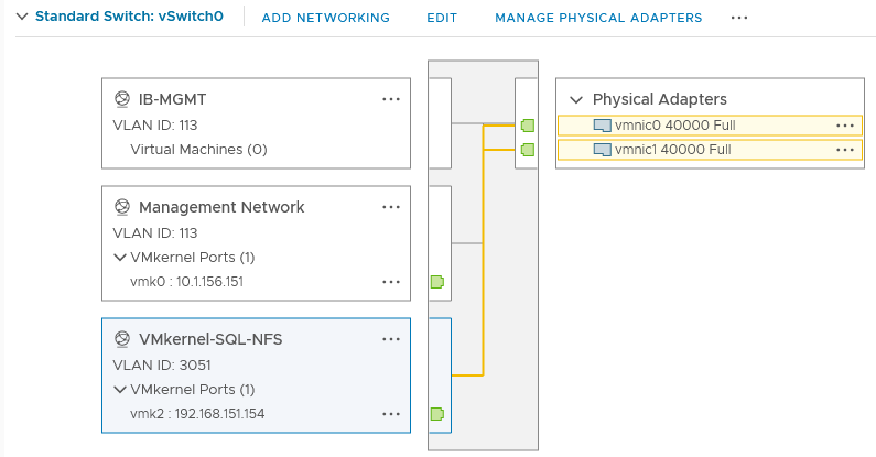
VMware ESXi vSwitch0 configuration
VMware ESXi iSCSI storage network
A default standard virtual switch, iScsiBootvSwitch, is created to access NetApp storage using the iSCSI protocol. This switch is created using one physical network adapter: vmnic4. The storage traffic to the NetApp storage array is divided into two fabrics through Fabric Interconnects A and B. Hence, a separate a separate standard switch is created for each fabric, allowing traffic on one vmnic adapter only. For instance, the iScsiBootPG-A port group is configured on iScsiBootvSwitch with only the vmnic4 adapter active (vmnic5 is unused). Similarly, the iScsiBootPG-B port group is configured on iScsiBootvSwitch-B with only the vmnic5 adapter active (vmnic4 is unused). This configuration enables the storage traffic to be segregated on each fabric.
Table 10 lists details about the ESXi iSCSI standard switches and their port groups.
Table 10. VMware vSphere standard switch iScsiBootvSwitch configuration and port group details
| Configuration |
Details |
| Switch name |
iScsiBootvSwitch |
| Number of physical adapters (uplinks) |
vmnic4 |
| MTU setting |
9000 |
| Port groups created on this standard switch |
|
| iScsiBootPG-A |
● Purpose: For ESXi host iSCSI boot from NetApp
● Active uplinks: vmnic4
● VLAN: 3011 (native VLAN)
● A VMKernel port (vmk1) is configured with an appropriate IP address on each ESXi host.
● MTU on vmk1: 9000
|
| Switch name |
iScsiBootvSwitch-B |
| Number of physical adapters (uplinks) |
vmnic5 |
| MTU setting |
9000 |
| Port groups created on this standard switch |
|
| iScsiBootPG-B |
● Purpose: For ESXi host iSCSI boot from NetApp
● Active uplinks: vmnic5
● VLAN: 3021 (native VLAN)
● A VMKernel port (vmk4) is configured with an appropriate IP address on each ESXi host.
● MTU on vmk4: 9000
|
Figure 17 shows the standard switches used for ESXi host iSCSI boot and the port groups as detailed in Table 10.
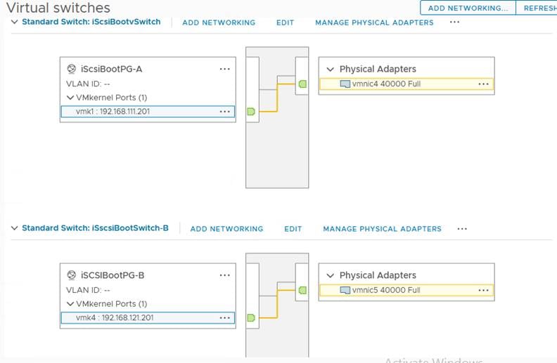
VMware ESXi standard switches for iSCSI
In this reference architecture, SQL Server virtual machine management traffic, SQL Server in-guest storage traffic, and ESXi vMotion traffic are moved to the vDS. Table 11 lists details about the vDS and the port groups created for each traffic type.
Table 11. VMware vDS SQL-vDS0 configuration and port group details
| Configuration |
Details |
| vDS name |
SQL-vDS0 |
| Number of physical adapters (uplinks) |
2 uplinks: vmnic2 (uplink 1) and vmnic3 (uplink 2) |
| MTU setting |
9000 |
| Distributed port groups created on the vDS |
|
| SQLVM-Mgmt-A |
● Purpose: For managing and accessing SQL Server virtual machines
● The uplinks are configured in an active-active setup so that both the uplinks will be used by SQL Server management traffic.
● VLAN: 901
|
| SQL-iSCSI-A |
● Purpose: For accessing NetApp storage directly from SQL Server virtual machines using the in-guest Microsoft software iSCSI initiator over Fabric A
● This traffic is pinned to only uplink. Hence, only uplink1 is configured as active, and the other uplink is unused.
● VLAN: 3011
|
| SQL-iSCSI-B |
● Purpose: For accessing NetApp storage directly from SQL Server virtual machines using the in-guest Microsoft software iSCSI initiator over Fabric B.
● This traffic is pinned to only uplink. Hence, only uplink2 is configured as active, and the other uplink is unused.
● VLAN: 3021
|
| vMotion-VMs |
● Purpose: For virtual machine migration from one host to another
● This traffic is pinned to Fabric B. Hence, only uplink2 is configured as active, and the other uplink is unused.
● VLAN:3000
● A VMkernel port (vmk3) is configured with appropriate IP addresses on each ESXI host.
● MTU on vmk3: 9000
|
Figure 18 shows all the distributed port groups configured on the vDS as detailed in Table 11. Figure 18 shows that guest iSCSI storage traffic through port group SQL-iSCSI-B is permitted only on Uplink B (Fabric B).
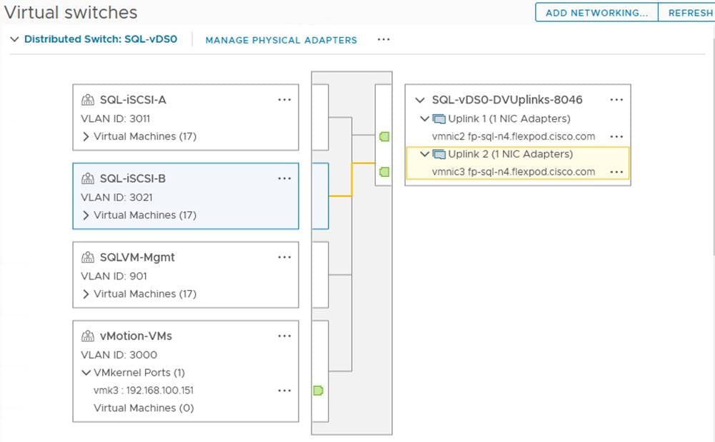
VMware vDS SQL-vDS0 and port groups
Verifying the VMware ESXi host NetQueue feature
As described in discussion of Cisco UCS Manager VMQ policy, the VMQ policy (with eight queues) is applied to the vmnic2 and vmnic3 physical adapters of the ESXi host. Figure 19 shows verification of VMQ policy being applied properly on ESXi (as the NetQueue feature). It also shows the number of transmit and receive queues available on each physical adapter that are part of the SQL-vDS distributed switch.
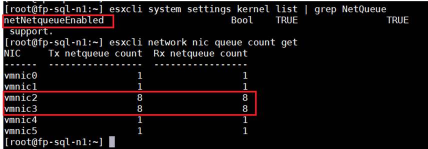
Verifying VMware ESXi NetQueue
For more information about the ESXi NetQueue features, refer to NetQueue and Networking Performance (at VMware.com).
For all other ESXi configurations, refer to the Cisco Validated Design for the base infrastructure.
VMware ESXi host logical network
Figure 20 shows a logical network diagram of the ESXi host. It depicts all the port groups and VMkernel adapters of the ESXi host described in the previous sections.
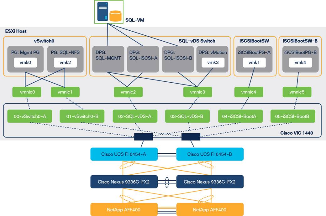
VMware ESXi host logical network diagram
As shown in Figure 20, SQL Server virtual machines are configured with the following networks:
● SQL-MGMT: The virtual network adapter is connected to the SQL-MGMT port group. It is used for SQL Server virtual machine management traffic and for SQL Server and client communication.
● SQL-ISCSI-A: The virtual network adapter is connected to the SQL-iSCSI-A port group. It is used to connect to NetApp storage using the in-guest iSCSI initiator over Fabric A.
● SQL-ISCSI-B: The virtual network adapter is connected to the SQL-iSCSI-B port group. It is used to connect to NetApp storage using the in-guest iSCSI initiator over Fabric B.
Note: The SQL-MGMT network is used for both SQL Server guest management and SQL Server client communication. Customers can create additional port groups with the appropriate VLAN to segregate SQL Server guest management traffic and SQL Server client traffic.
VMware ESXi datastore provisioning for Microsoft Windows virtual machines from ONTAP tools plug-in for VMware vCenter
Verify that the ONTAP tools 9.8 plug-in for vCenter is installed as described in the Deployment and Setup Guide for ONTAP Tools for VMware vSphere 9.8.
To provision the ESXi datastore for Windows virtual machines from the vCenter ONTAP tools plug-in, follow these steps:
1. Log in to the vCenter web user interface client and click ONTAP tools (Figure 21).
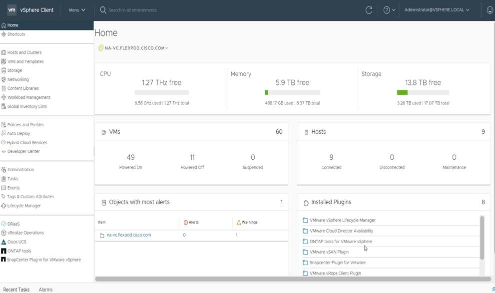
NetApp ONTAP tools homepage
2. Click Provision (Figure 22).
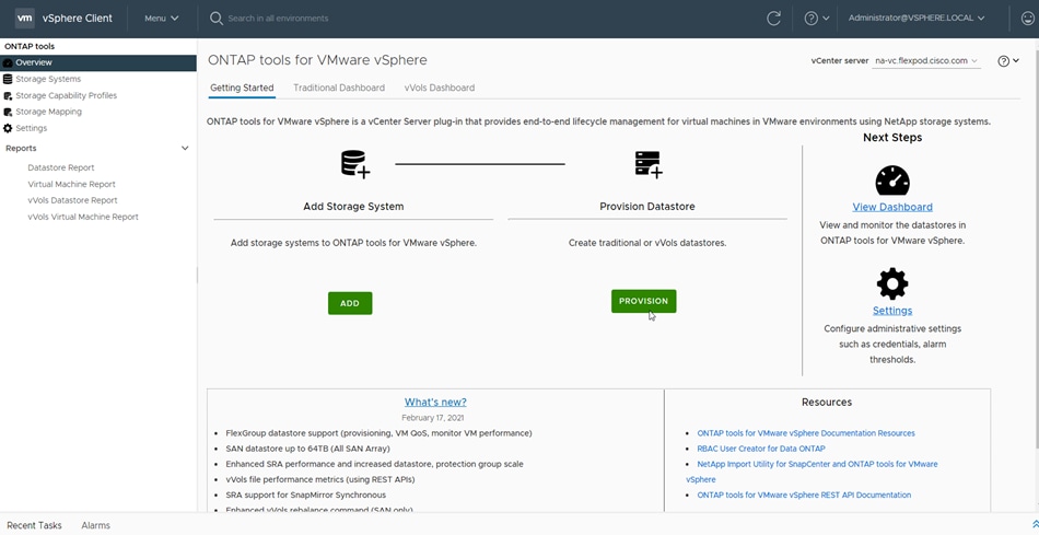
3. Browse to select an available ESXi cluster to provision the datastore (Figure 23).
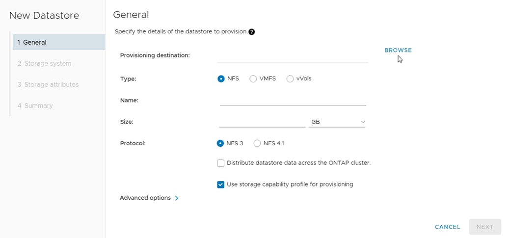
Creating a with NetApp ONTAP tools
4. Select an appropriate ESXi cluster to which the SQL Server virtual machines will be deployed in the new datastore (Figure 24).
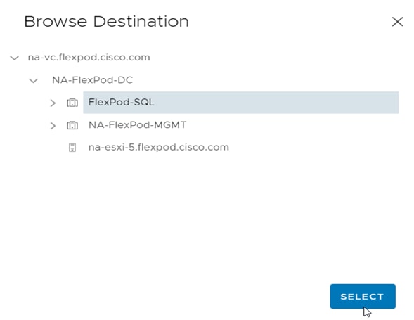
Selecting a VMware ESXi cluster with NetApp ONTAP tools
5. Fill in the name of the datastore, the size, and the NFS protocol (Figure 25). Click Next.
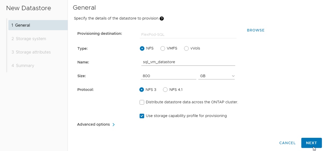
Volume specifications
6. Select the storage capability profile, storage system, and storage virtual machine (Figure 26). Click Next.
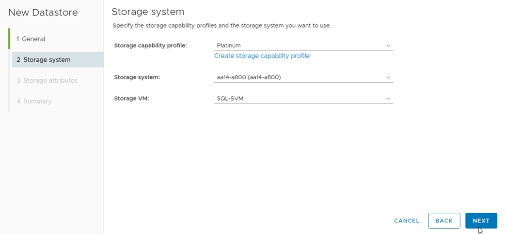
Volume QoS specifications
7. Select attributes to provision the storage for FlexVol for the datastore (Figure 27). Click Next.
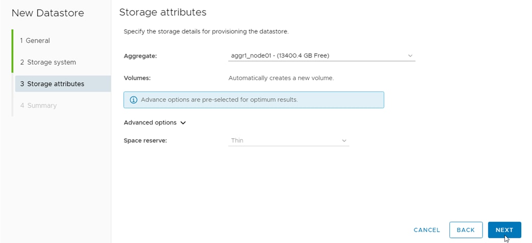
Selecting NetApp attributes
8. Review the summary and click Finish (Figure 28).
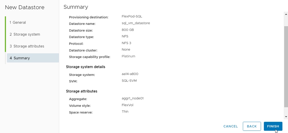
Summary of NetApp volume creation using NetApp ONTAP tools
9. After acknowledging the start of the operation, track the progress in the vCenter task view.
10. After the task is complete, check the datastore configuration in the datastore view of vCenter (Figure 29).
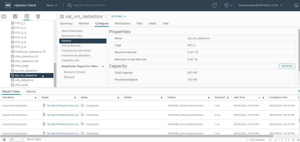
Tracking the status of volume creation using NetApp ONTAP tools
11. Repeat steps 1 through 10 for one more datastore and select a different aggregate to provision. You should distribute the virtual machines on two datastores residing on different aggregates, so the storage capacity and performance are balanced.
Virtual machine creation and deployment to host Microsoft SQL Server databases
This section describes best practices and recommendations for creating and deploying SQL Server virtual machines on the FlexPod system.
Beginning with vSphere 6.5, changing the Cores per Socket setting no longer influences virtual non-uniform memory access (vNUMA) or the configuration of the vNUMA topology. The configuration of vSockets and Cores per Socket now affects only the presentation of the virtual processors to the guest OS, something potentially relevant for software licensing. Because SQL Server uses core-based licensing, changing the Cores per Socket value does not affect anything. One general recommendation is that as long as the CPU and memory requirements of a virtual machine are within the single physical socket limits, you do not have to change the default setting for Cores per Socket. If the CPU and memory requirements of a virtual machine exceed the single physical socket limits, make sure to equally distribute the CPU and memory resources of the virtual machine across the physical sockets.
This setting can affect the behavior of the SQL Server Standard edition, which can support the lesser of 4 sockets or 24 cores. Therefore, be sure that no more than 4 sockets are configured when using Standard edition.
SQL Server database transactions are usually CPU and memory intensive. In heavily OLTP database systems, you should reserve all the memory allocated to the SQL Server virtual machines. This approach helps ensure that the memory assigned to the SQL Server virtual machines is committed, and it eliminates the possibility that ballooning and swapping will occur.
Figure 30 shows a SQL Server Standard edition virtual machine configuration. Only two virtual sockets are configured, by adjusting the Cores per Socket setting. Note that the memory reservation box is checked.
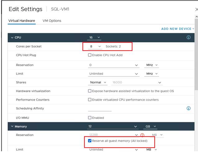
Cores per socket and memory reservation for Microsoft SQL Server virtual machines
You should configure the virtual machine network adaptors with VMXNET3. VMXNET 3 is the latest generation of paravirtualized NICs designed for performance. It offers several advanced features, including multiple-queue support, receive-side scaling, IPv4/IPv6 offloads, and message-signaled interrupt (MSI) and MSI-X interrupt delivery.
For this solution, each SQL Server virtual machine is configured with three network adapters, with VMXNET3 as the adapter type. One adapter is connected to the SQLVM-Mgmt port group for virtual machine management and SQL Server access, and the second and third network adapters are connected to the SQL-iSCSI-A and SQL-iSCSI-B port groups respectively. These adapters are used for direct NetApp storage access using the Microsoft software iSCSI initiator over Fabrics A and B respectively. Figure 31 shows the SQL Server virtual machine configured with three adapters.
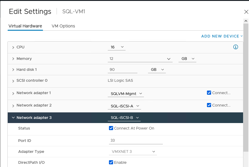
Virtual network adapter configuration
Guest operating system installation and configuration
This section provides configuration recommendations for the Windows guest operating system for hosting SQL Server databases. For a detailed step-by-step process for installing the Windows Server 2019 guest operating system in the virtual machine, refer to the VMware documentation.
When the Windows guest operating system is installed in the virtual machine, you also should install the VMware tools as explained here.
The default power policy option in Windows Server 2019 is Balanced. For SQL Server database deployments, you should set the power management option to High Performance for optimal database performance, as shown in Figure 32.
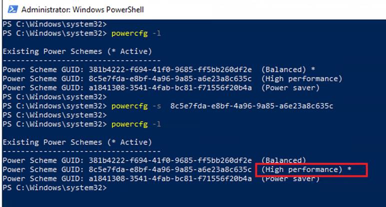
Guest power settings
Adding a guest virtual machine to the domain
You should change the default Windows guest virtual machine name and join the virtual machine to the domain before you proceed with the storage configuration for the guest virtual machine. For detailed instructions about how to change the guest name and join the guest, click here.
Using the server manager, enable the Remote Desktop feature to remotely manage the guest virtual machine and turn off the firewalls in the guest virtual machine. Figure 33 shows the final configuration after SQLVM1 is joined to the flexpod.cisco.com domain, enabling Remote Desktop and turning off the firewall settings and corresponding IP addresses of the management and iSCSI storage interfaces.
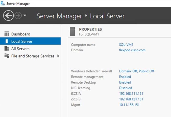
Microsoft Windows guest server configuration
Storage configuration in the Microsoft SQL Server virtual machine
This section describes the guest configuration for jumbo frames, the installation and configuration of multipath software, and the iSCSI initiator configuration for connecting NetApp AFF A800 storage LUNs directly from the SQL Server virtual machines.
Enabling jumbo frames on storage network interfaces
Enabling jumbo frames for storage traffic provides better I/O performance for SQL Server databases. In the SQL Server guest virtual machine, make sure that jumbo frames are set to 9000 on the Ethernet adapter used for NetApp storage connectivity as shown in Figure 34. After enabling jumbo frames, make sure the virtual machine can reach the storage with the maximum packet size without fragmenting the packets, as shown in the figure.
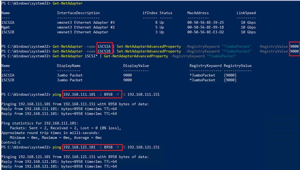
Enabling and verifying jumbo frames on storage interfaces in Microsoft SQL Server guest virtual machines
Configuring multipath software
NetApp recommends using Windows native multipath drivers to manage storage connections in the Windows Server 2019 guest virtual machine. Figure 35 shows the installation of the multipath I/O feature using PowerShell. After installing this feature, enable Microsoft Device Specific Module (MSDSM) to automatically claim SAN disks for Microsoft Multipath I/O (MPIO) for the iSCSI bus type. Then restart the virtual machine to make the changes take effect.
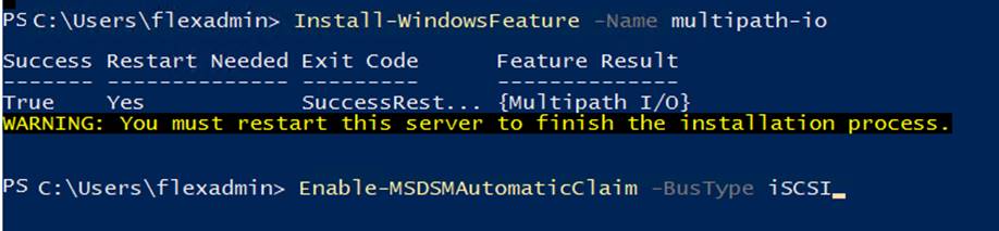
Installing Microsoft Windows native multipath software
After enabling the MPIO feature in Windows, download and install the NetApp Windows Unified Host Utilities on the virtual machine. To download and install the host utilities, follow these steps.
1. Download NetApp Host Utilities Version 7.1 for Windows from this link:
https://mysupport.netapp.com/documentation/productlibrary/index.html?productID=61343
2. Unzip the file and run the executable file. The NetApp Windows Unified Host Utilities setup wizard is launched. Click Next.
3. Click Yes, install support for Multipath I/O, and click Next.
4. Accept the default destination folder and click Next.
5. Click Next and then click Install to start the installation of the host utilities.
6. After the installation is complete, click Finish and restart the virtual machine.
7. After the virtual machine is restarted, verify that appropriate device drivers are added in the MPIO utility as shown in Figure 36.
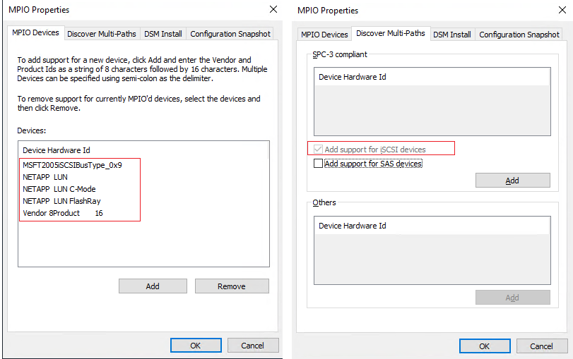
Verifying NetApp MPIO settings
Configuring the Microsoft software iSCSI initiator
This section provides steps for configuring the in-guest iSCSI initiator for virtual machines to directly access the NetApp storage LUNs. To configure the iSCSI initiator within the guest, follow these steps:
1. Start the Microsoft iSCSI initiator service and set it to start automatically as shown in Figure 37. Find the virtual machine initiator ID and make a note of it, because you will need it to grant the NetApp storage LUN access to the guest virtual machine.
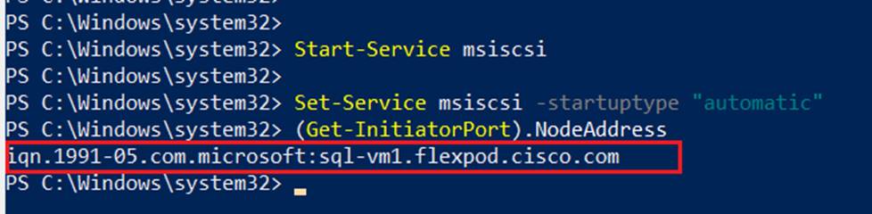
Enabling iSCSI initiator
2. Open the NetApp ONTAP System Manager and create an initiator group using the iSCSI initiator name previously noted. After the initiator group for the virtual machines is created, assign the required LUNs to the initiator group. To assign a LUN to an initiator group, you need to edit the LUN and select the required initiator group. For instance, sql_db1_vm1 LUN is assigned to the SQL-VM1 initiator group in Figure 38.
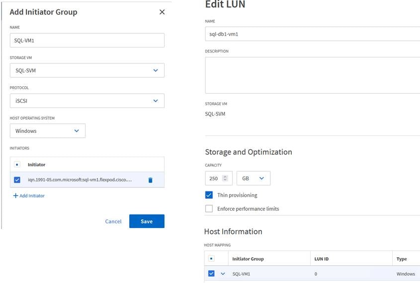
Configuring the initiator group in NetApp storage
3. Run the following PowerShell commands on the guest virtual machine to establish connections to the NetApp target iSCSI IP addresses. For each virtual machine, you need to replace InitiatorPortalAddress with the appropriate guest iSCSI IP address.
New-IscsiTargetPortal -TargetPortalAddress 192.168.111.100 -InitiatorPortalAddress 192.168.111.151
New-IscsiTargetPortal -TargetPortalAddress 192.168.111.101 -InitiatorPortalAddress 192.168.111.151
New-IscsiTargetPortal -TargetPortalAddress 192.168.121.100 -InitiatorPortalAddress 192.168.121.151
New-IscsiTargetPortal -TargetPortalAddress 192.168.121.101 -InitiatorPortalAddress 192.168.121.151
4. Connect to the NetApp targets using the following PowerShell commands:
$target = Get-IscsiTarget
Connect-IscsiTarget -TargetPortalAddress 192.168.111.100 -InitiatorPortalAddress 192.168.111.151 -NodeAddress $target.NodeAddress -IsMultipathEnabled $true -IsPersistent $true
Connect-IscsiTarget -TargetPortalAddress 192.168.111.101 -InitiatorPortalAddress 192.168.111.151 -NodeAddress $target.NodeAddress -IsMultipathEnabled $true -IsPersistent $true
Connect-IscsiTarget -TargetPortalAddress 192.168.121.100 -InitiatorPortalAddress 192.168.121.151 -NodeAddress $target.NodeAddress -IsMultipathEnabled $true -IsPersistent $true
Connect-IscsiTarget -TargetPortalAddress 192.168.121.101 -InitiatorPortalAddress 192.168.121.151 -NodeAddress $target.NodeAddress -IsMultipathEnabled $true -IsPersistent $true
5. Verify the connections as shown in Figure 39. You should see four iSCSI connections established to the NetApp storage.
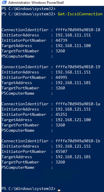
Verifying connections to the NetApp target
6. Open Disk Management and initialize and format the disks with the NTFS file system and a 64-KB allocation unit size. Under Disk Management, right-click the disk and select Properties. In the NetApp LUN C-Mode Multi-Path Disk Device Properties dialog box, click the MPIO tab. You should see four storage connections being established: two being active and optimized and the other two being active and unoptimized. These represent the path states defined by the SCSI Asymmetric Logical Unit Access (ALUA) protocol, with the active and optimized path being the path to the primary storage controller for the LUN, and the active and unoptimized being the path to the high-availability partner controller. Figure 40 shows the virtual machine using the Disk Management tool.
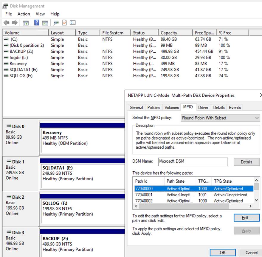
NetApp LUNs in the Microsoft SQL Server guest virtual machine
Microsoft SQL Server installation and configuration
Many recommendations and best-practices guides are available for most SQL Server settings. But the relevance of these recommendations vary from one database deployment to another. Therefore, you should thoroughly test and validate critical settings and determine whether or not to implement the specific database environment. The following sections describe some of the main SQL Server installation and configuration settings that have been used and tested on the FlexPod system. The rest of the SQL Server options are kept at their default settings and used for performance testing.
Microsoft SQL Server 2019 installation
This section provides a high-level installation process. For detailed step-by-step instructions for installing SQL Server 2019 on the Windows operating system, refer to the Microsoft document Install SQL Server from the Installation Wizard (Setup).
To install Microsoft SQL Server 2019, follow these steps:
1. In the Server Configuration window of the SQL Server 2019 Setup wizard, make sure that instant file initialization is enabled by selecting the checkbox as shown in Figure 41. With this setting enabled, SQL Server data files are instantly initialized, avoiding zeroing operations.
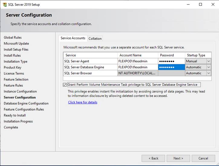
Enabling the instant file initialization option for data files
2. In the Database Engine Configuration window on the TempDB tab, make sure that the number of TempDB data files is equal to 8 when the number of virtual CPUs (vCPUs) or logical processors of the SQL Server virtual machine is less than or equal to 8. If the number of logical processors is more than 8, start with 8 data files and try adding data files in multiples of 4 when you notice contention on the TempDB resources. Figure 42 shows 8 TempDB files chosen for a SQL Server virtual machine that has 8 vCPUs. Also, as a best practice, make sure that the TempDB data and log files are in two different volumes.
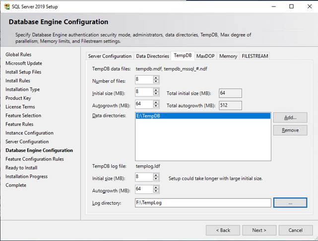
TempDB configuration
3. Complete the SQL Server installation by clicking Next and then Finish.
4. After SQL Server is installed successfully, be sure a SQL Server service account (used for SQL Server database service) is added to the “Lock pages in memory” policy using the Windows Group Policy Editor. Granting the “Lock pages in memory” user the right to the SQL Server service account prevents SQL Server buffer pool pages from being paged out by the Windows server. Figure 43 shows how to enable this option. Also, if a domain account is used as a SQL Server service account that is not a member of the local administrator group, then add a SQL Server service account to the “Perform volume maintenance tasks” policy using the Local Security Policy Editor.
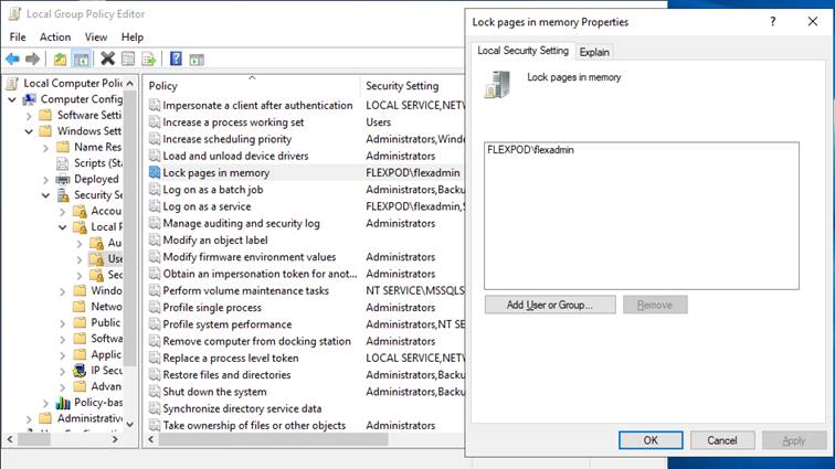
Enabling “Lock pages in memory” for Microsoft SQL Server
The SQL Server can consume all the memory allocated to the virtual machine. Setting the maximum server memory allows you to reserve sufficient memory for the operating system and other processes running on the virtual machine. Ideally, you should monitor the overall memory consumption of SQL Server during regular business hours and determine the memory requirements. To start, allow SQL Server to consume about 80 percent of the total memory, or leave at least 2 to 4 GB of memory for the operating system. The Maximum Server Memory setting can be dynamically adjusted based on your memory requirements.
Number of data LUNs and database files
For user databases that have intensive Data Manipulation Language (DML) operations, you should create multiple data files of the same size to reduce allocation contention. If you have demanding I/O workload deployments, use more than one LUN for the database data files, to help provide optimal distribution of I/O across the storage controllers. For optimal database implementations on a SAN, NetApp recommends the technical report linked here, which discusses the best practices on modern SANs.
NetApp SnapCenter configuration for Microsoft SQL Server database backup, restore, cloning, and protection
To configure SnapCenter to prepare for SQL Server database operations, you need to perform a number of tasks. You add hosts, configure hosts, provision storage to hosts for SQL Server data and logs, provision storage to hosts for SnapCenter logs, create SQL Server database resource groups, and create backup schedule policy.
Add hosts (Microsoft Windows virtual machines) to NetApp SnapCenter
When hosts are added to SnapCenter, you need to install the SnapCenter plug-in for SQL Server and the SnapCenter plug-in for Windows on the host.
1. For Host Type, choose Windows and enter the host name and credentials of the administrator user. Select the Microsoft Windows and Microsoft SQL Server plug-ins (Figure 44).
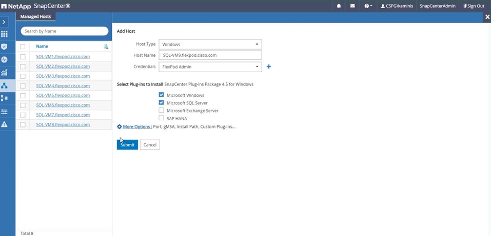
Adding a new Microsoft SQL Server virtual machine host
2. Configure the directory for SnapCenter logs for the host (Figure 45).
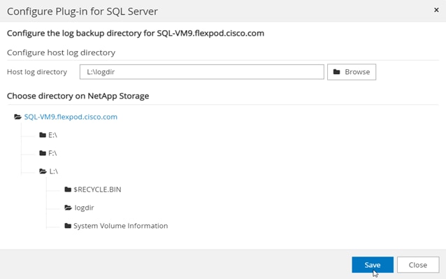
Select the LUN for the NetApp SnapCenter log directory
Provision storage for Microsoft Windows virtual machines using NetApp SnapCenter
SnapCenter can provision only storage LUNs (disk) to Windows virtual machines that are added to SnapCenter.
1. Select the storage SVM and the LUN path (FlexVol volume on the SVM). Provide the LUN name, cluster (block) size, and label for the Windows file system (Figure 46).
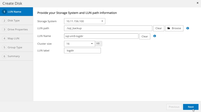
NetApp SnapCenter log LUN specifications
2. Enter all the required parameters, review the summary, and click Finish to complete the disk creation task (Figure 47).
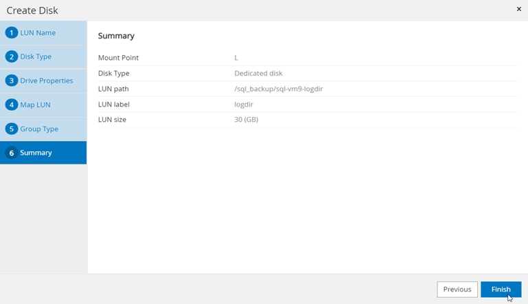
Summary of NetApp SnapCenter log LUN provisioning
Resource groups are groups of SQL Server databases and corresponding logs that are backed up together. A backup policy is associated with the resource group to back up the SQL Server databases and retain a certain number of backups as defined in the policy.
1. Enter the name of the new resource group, any tag for the group, and the custom name format, if required. Select a specific host or all hosts, resource type databases, and the SQL Server instance. Select the user databases to add to the resource group (Figure 48). Select more databases from different SQL Server instances if needed, to add those to the same resource group to be backed up simultaneously according to the same policy and schedule.
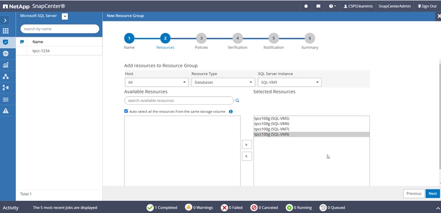
Selecting databases for resource groups
2. Select one or more backup policies from the drop-down list of available policies, or create new policies if required (Figure 49).
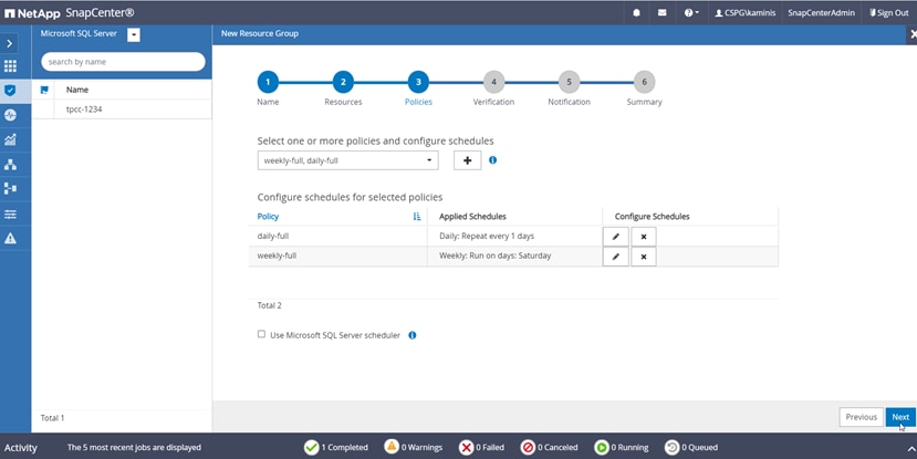
Adding more scheduling policies
3. Select a verification server and then configure notification settings. Review the summary and click Finish (Figure 50).
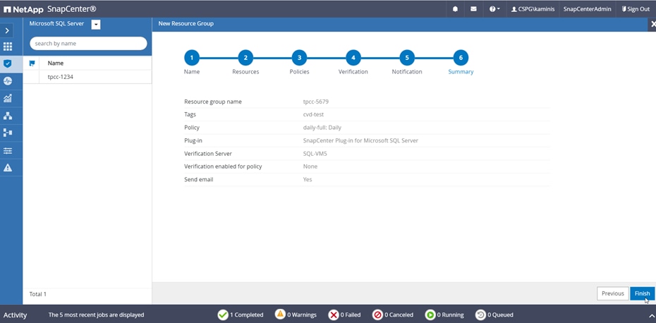
Summary of resource group configuration
Verify on-demand backup of Microsoft SQL Server databases
The resource group for SQL Server databases should have on-demand backup enabled.
1. Select the Resources view. Click a resource group and click Backup Now (Figure 51).
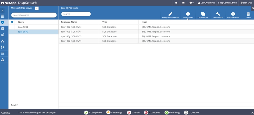
Triggering backup using the resource group
2. Select a policy to use for the on-demand backup. Select “Verify after backup” and then click Backup. Verify the activity status of the triggered backup job as shown in Figure 52.
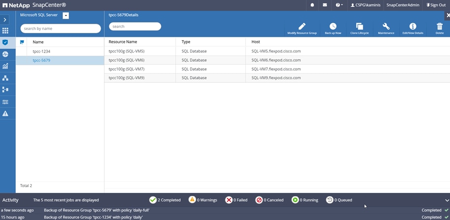
Backup status of the resource group
Use NetApp storage snapshots for data protection and quick recovery of databases
SnapCenter can create application-consistent snapshot copies and complete data protection operations, including snapshot copy-based backup, clone, restore, and backup verification operations.
You need to add the ONTAP SVM that owns the volumes on which the user databases reside under the storage systems in SnapCenter so that the SnapCenter server can communicate with the storage SVM. After a resource group is created and a backup policy is attached to it, you can proceed with backup jobs.
When you start the backup process for a given user database, a copy-based backup in the form of a snapshot is created on the same volume on which the user database resides. This snapshot copy can be used for data-protection operations such as the recovery and cloning of databases (Figure 53).
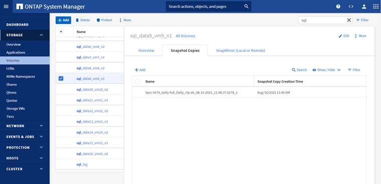
Viewing NetApp storage snapshot created after a backup job is completed in NetApp SnapCenter
Verify Microsoft SQL Server database restoration from backup
Before proceeding, verify that a backup of the SQL Server databases resource group has been created using SnapCenter.
1. Select the Resources view and then click a resource group name. Select the name of a database resource to restore from a backup. The list of backups for the selected resource is displayed. Click the name of the backup to restore the database from (Figure 54).
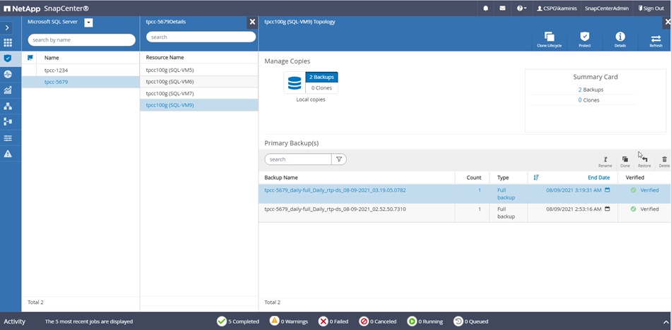
Select the backup to restore the database
2. Select the host to which the database is restored and the desired recovery of logs from backup. Specify the pre-restore and post-restore options for the database. Enter notification email details for the restore job and review the summary of the restore task. Then click Finish (Figure 55).
Restore task summary
3. Navigate to the Monitor tab and view the job status of the restore operation. View the details or download the log if needed (Figure 56).
Monitor the restore job
Verify Microsoft SQL Server database cloning from backup
Before proceeding, verify that the backup of the SQL Server databases resource group has been created using SnapCenter.
1. Select the Resources view and click a resource group name. Click the name of a database resource to clone from a backup. The list of backups for the selected database is displayed. Select the backup to clone the database from and click Clone (Figure 57).
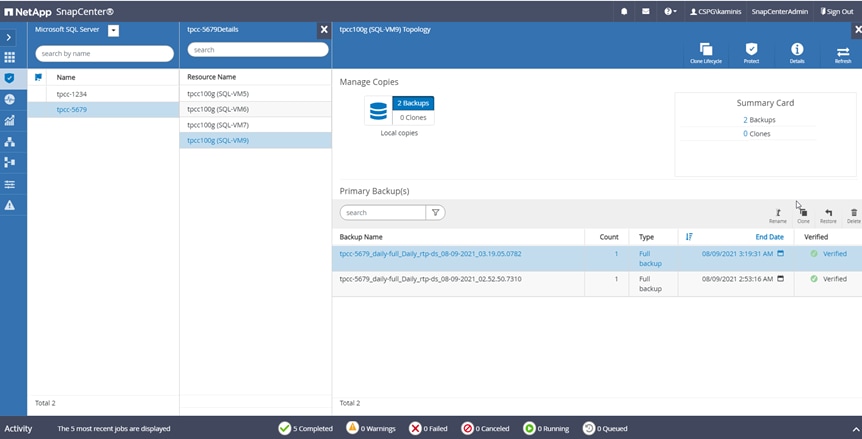
Select the backup to clone the database
2. Enter clone server, SQL Server instance, and clone name. Select the option for the Windows mountpoint at which to mount the database.
3. Choose the log options. Specify the optional prescripts and postscripts to run before and after the clone operation. Configure the notification email settings and review the summary of the clone operation to be triggered (Figure 58).
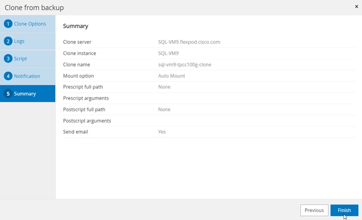
Clone operation summary before starting the cloning process
4. Navigate to the Monitor view, click Jobs, and monitor the status of the clone job (Figure 59).
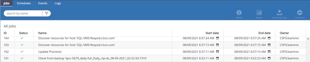
Monitor the progress of the clone job
For detailed configuration and deployment steps, refer to the “SnapCenter Configuration for SQL Database Backup, Restore, Cloning, and Protection” section in the following document: https://www.cisco.com/c/en/us/td/docs/unified_computing/ucs/UCS_CVDs/mssql2019_flexpod.html.
This section provides a high-level summary of the testing and validation results for the FlexPod solution. The following tests were performed on the solution:
● Demonstrate the maximum I/O capacity of the NetApp A800 storage array (single pair of controllers) using the DiskSpd tool for typical 70 percent read and 30 percent write workloads.
● Demonstrate OLTP database performance scalability for both scale-up and scale-out scenarios using a single Cisco UCS B200 M6 Blade Server and multiple Cisco UCS B200 M6 Blade Servers with a sample 100-GB test database using the HammerDB tool.
● Demonstrate high I/O performance with OLTP database workloads.
● Demonstrate NetApp storage snapshots for data protection and quick recovery of databases.
This FlexPod configuration was successfully verified by performing multiple failure tests to determine database persistence and performance.
● Network link failures tests between Cisco UCS fabric interconnects and Cisco UCS 5100 Series blade chassis and fabric interconnects and upstream Cisco Nexus switches were performed to validate the storage connectivity from the Cisco UCS B200 M6 blades and NetApp A800 storage array.
Validated hardware and software
Table 12 lists the hardware and software versions used during the solution validation process. Note that Cisco and NetApp have interoperability matrixes that should be referenced to determine support for any specific implementation of FlexPod. See the following documents for more information:
● NetApp Interoperability Matrix Tool
● Cisco UCS Hardware and Software Interoperability Tool
Table 12. Validated hardware and software versions
| Device |
Image |
|
| Computing |
● Cisco UCS 6454 Fabric Interconnect
● 1 Cisco UCS 5108 blade chassis with 2 Cisco UCS 2408 I/O modules
● 4 Cisco UCS B200 M6 blades, each with 1 Cisco UCS VIC 1440 adapter and port expander card
|
Release 4.2(1d) |
| CPU |
2 Intel Xeon Gold 6330 CPUs at 2.0 GHz, with 42-MB Layer 3 cache and 28 cores per CPU |
|
| Memory |
1024 GB (16 x 64-GB DIMMS operating at 3200 MHz) |
|
| Network |
2 Cisco Nexus 9336C-FX2 Switches |
Release 9.3(7) |
| Storage |
2 NetApp AFF A800 storage controllers with 24 x 1.8-TB NVMe SSDs |
NetApp ONTAP 9.8 |
| Hypervisor |
VMware vSphere 7.0 |
Release 7.0.2, Build 17867351 |
|
|
Cisco UCS VIC enic driver |
Release 1.0.35.0-1OEM.670.0.0.8169922 |
| Guest OS |
Microsoft Windows Server 2019 |
|
| Database |
Microsoft SQL Server 2019 |
|
| Testing tool |
HammerDB Version 4.0 |
|
Test results
The test results are summarized here.
Test of I/O capacity of NetApp storage controllers
This FlexPod solution was first tested with a synthetic I/O testing tool, in this case, DiskSpd, to help ensure that the system is deployed optimally and configured following all the FlexPod best practices. For this test, 12 virtual machines were deployed (3 virtual machines per node) across a 4-node ESXi cluster. Each virtual machine was configured with two direct iSCSi disks from the NetApp A800 storage array using the in-guest Microsoft iSCSI initiator. The DiskSpd tool was installed on each virtual machine and configured to run the I/O test on two disks with a 70:30 percent read-write workload with an 8-KB block size.
The following script was run on all 12 virtual machines concurrently:
.\diskspd -t8 -o4 -b8k -r -w30 -d1800 -Sh -L -c15G E:\testfile.dat > C:\DiskSpd_7030RW_8T_4OIO_8Kran_disk1.txt
.\diskspd -t8 -o4 -b8k -r -w30 -d1800 -Sh -L -c15G F:\testfile.dat > C:\DiskSpd_7030RW_8T_4OIO_8Kran_disk2.txt
The screen shot in Figure 60 (captured using the NetApp AIQUM tool) shows the IOPS and throughput driven by all 12 virtual machines. They were able to drive nearly one million I/O operations with a 70:30 percent read-write ratio with latency of less than 0.5 millisecond. As shown in Figure 60, storage system utilization averaged over 91 percent, indicating that the storage system was at or near its maximum performance capability. Although the system could support additional workload that would drive CPU utilization even higher, NetApp recommends that storage systems operate below 80 percent utilization during normal operations to prevent significant performance impacts during a controller failure scenario. For additional I/O performance requirements, another pair of NetApp storage controllers can be added to the existing cluster. NetApp recommends following the best practices for VMware vSphere when configuring ESXi for any applications workloads.
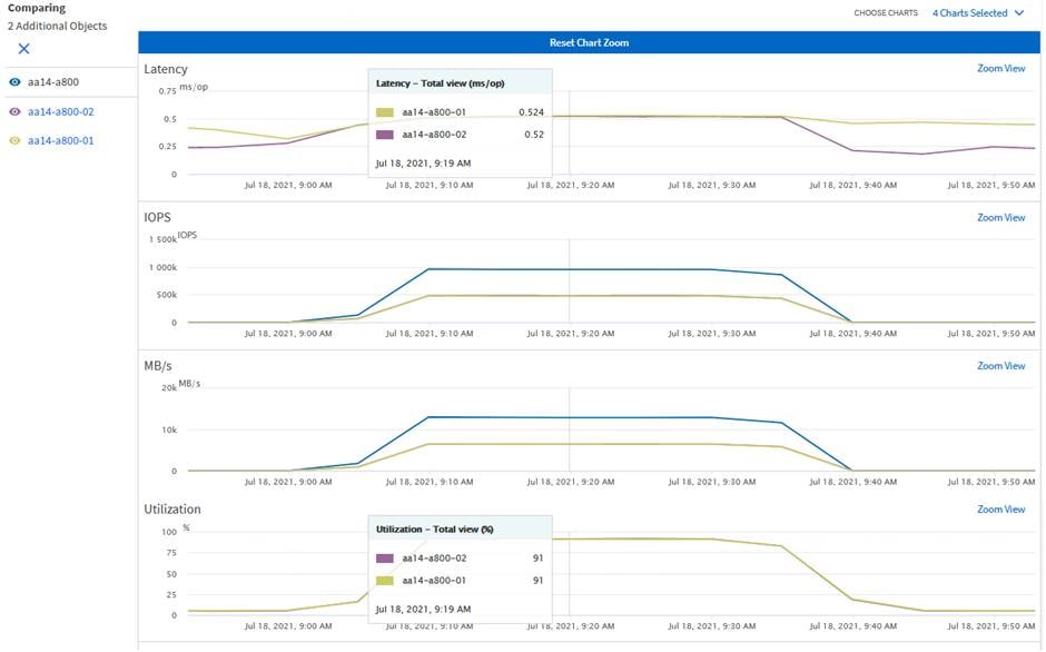
Demonstrating the maximum I/O capacity of NetApp A800 controllers (single pair)
Test of database performance scalability in a single Cisco UCS B200 M6 host on VMware ESXi
The objective of this test is to demonstrate how a single Cisco UCS B200 M6 host can respond as more SQL Server workload virtual machines are added to the host. Table 13 lists the virtual machine configuration and database schema details used for this test, which was run with the HammerDB tool. Each virtual machine was configured with eight vCPUs and 12 GB of memory. Each SQL Server virtual machine was stressed at about 60 to 70 percent of the guest CPU, generating about 25,000 to 27,000 total I/O operations at a 70:30 percent read-write ratio.
Table 13. Virtual machine configuration used for single-host scalability test
| Component |
Details |
| Virtual machine configuration |
8 vCPUs with 12 GB of memory (9 GB allocated to SQL Server) |
| Storage volumes for database |
● 1 x 250-GB LUN for data files
● 1 x 200-GB LUN for log files
● 1 x 90-GB LUN for OS
|
| Database |
SQL Server 2019 Evaluation Edition |
| Guest operating system |
Windows Server 2019 |
| Workload per virtual machine |
● Database size: 100 GB
● Targeted total IOPS: 25000 to 27000
● Read-write ratio: 70:30%
● Guest CPU utilization: About 60 to 70%
● Performance metrics collected:
◦ Transactions per second (TPM/60) ◦ Windows Perfmon I/O metrics ◦ ESXi ESXTOP metrics |
The graph in Figure 61 shows how multiple SQL Server virtual machines performed on a single ESXi host. As shown, a single SQL Server virtual machine delivered about 4700 TPS. As more SQL Server virtual machines were added to the same host (scaled to five virtual machines), the TPS scaled nearly linearly because no bottlenecks were discovered within the Cisco UCS B200 M6 host or in the NetApp A800 storage. With a single SQL Server virtual machine workload, about 13.5 percent of ESXi host CPU utilization was noticed. As more virtual machines were added to the host, CPU utilization of the underlying Cisco UCS B200 M6 host also scaled nearly linearly, as shown in Figure 61.
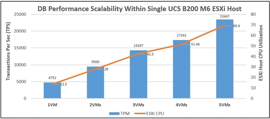
Database performance scalability within a single Cisco UCS B200 M6 host on VMware ESXi
The graph in Figure 62 shows the disk data transfers (IOPS) and latency details for the corresponding single-host ESXi test described above. The performance numbers were captured using the Windows Perfmon tool at the guest OS level. As shown in Figure 62, a single SQL Server virtual machine delivered nearly 27000 IOPS. As more SQL virtual machines were added to the same host, the IOPS scaled nearly linearly. The write latencies (captured using guest Perfmon) stayed within 1.5 milliseconds.
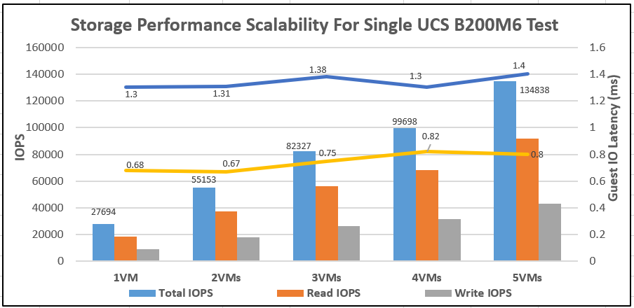
IOPS scalability for the workload running within a single Cisco UCS B200 M6 host on VMware ESXi
Test of database performance scalability across a four-node VMware ESXi cluster
The objective of this test is to demonstrate the database performance scalability when multiple SQL Server virtual machines are deployed across a four-node ESXi cluster built using Cisco UCS B200 M6 blades and a NetApp A800 storage array, a configuration typically seen in real-world implementations.
For this multinode ESXi test, the same virtual machine configuration and database schema as described in Table 13 was used. This test started with 4 virtual machines spread across the cluster and then was scaled by groups of 4 virtual machines up to 16 virtual machines (4 virtual machines per ESXi host).
As shown in Figure 63, 4 virtual machines (1 virtual machine per node) collectively delivered about 18,500 TPS. As more SQL Server virtual machines were added to the cluster (up to 16 virtual machines), TPS scaled nearly linearly. With a single SQL Server virtual machine workload, about 14 percent ESXi host CPU utilization was noticed. As more virtual machines were added across the ESXi cluster, CPU utilization of the cluster also scaled nearly linearly, as shown in the figure.
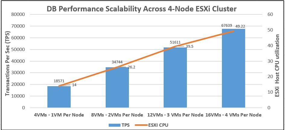
Database performance scalability across a 4-node VMware ESXi cluster
The graph in Figure 64 shows the disk data transfers (IOPS) and latency details for the corresponding multihost ESXi test described above. As shown in the figure, 4 virtual machines collectively delivered about 100,000 IOPS. As more SQL Server virtual machines were added to the cluster (up to 16 virtual machines), the IOPS scaled nearly linearly. The write latencies (captured with the guest OS Perfmon tool) stayed within 2 milliseconds.
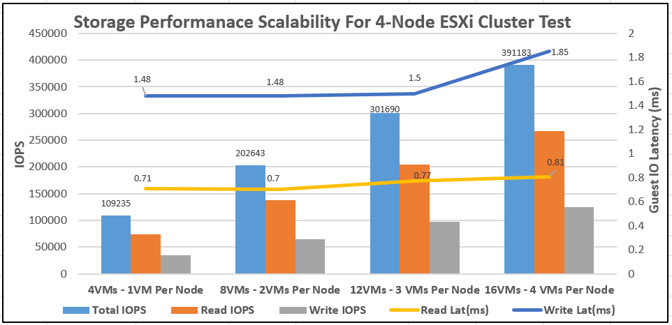
IOPS scalability for a workload running across a 4-node VMware ESXi cluster
With 16 virtual machines tested across the cluster, the NetApp AFF A800 delivered about 400,000 IOPS, with the storage controller’s CPU utilization rate at about 60 to 65 percent and the ESXi cluster CPU utilization rate at about around 50 percent. These values indicate that enough computing and storage resources were still available in the system, and that the system could support additional workloads.
Test to demonstrate high I/O performance for OLTP database workloads
The goal of this test is to drive higher IOPS on the NetApp AFF A800 storage array with OLTP database workloads. During the performance scalability tests described in the previous sections, the storage subsystem was not stressed to its maximum levels. To test and achieve higher storage performance, SQL Server virtual machines were configured with more resources to support more database users, thereby driving more IOPS. SQL Server virtual machines were also configured with less memory (6 GB) to help ensure that most of the data requests generated by the HammerDB tool landed on the storage array rather than being served by the SQL Server buffer cache. Table 14 summarizes the virtual machine configuration used for this test.
Table 14. Virtual machine configuration used for the higher I/O performance test
| Component |
Details |
| Virtual machine configuration |
16 vCPUs, with 8 GB of memory (6 GB allocated to SQL Server) |
| Storage volumes for database |
● 1 x 250-GB LUN for data files
● 1 x 200-GB LUN for log files
● 1 x 90-GB LUN for OS
|
| Database |
SQL Server 2019 Evaluation Edition |
| Guest operating system |
Windows Server 2019 |
| Workload per virtual machine |
● Database size: 100 GB
● Targeted total IOPS: 35000 to 37000
● Read-write ratio: 70:30%
● Guest CPU utilization: About 45 to 55%
● Performance metrics collected: NetApp Active IQ Manager
|
For this test, 16 SQL Server virtual machines were configured and deployed across the 4-node ESXi cluster. SQL Server databases were stressed using the HammerDB instances running on a separate client machine. The two graphs in Figure 65 show the storage metrics collected using NetApp Active IQ Manager during the test. Each SQL Server virtual machine was stressed to 45 to 55 percent CPU utilization using 45 HammerDB users, each contributing 35,000 to 37,000 IOPS with a 70:30 percent read-write ratio, resulting in a total of 580,000 IOPS, with latency of less than 1 ms, as shown in the figure.
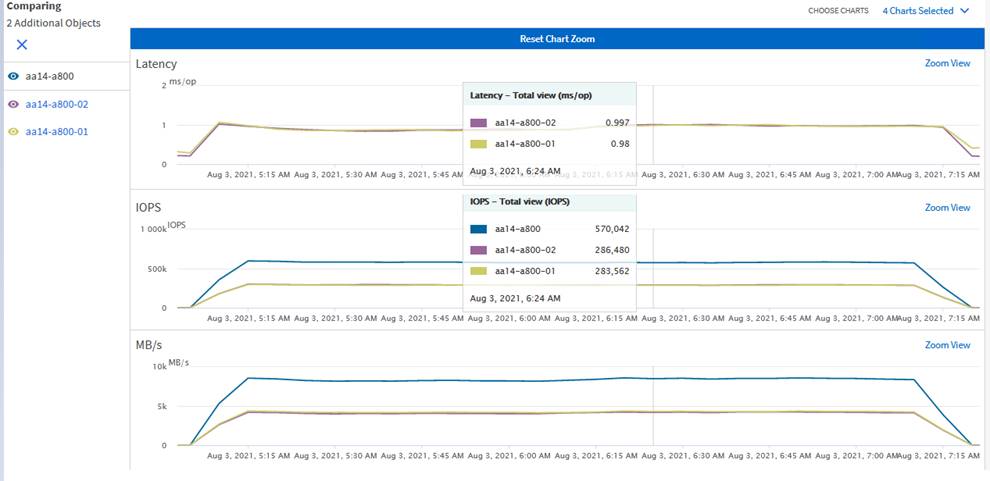
Demonstrating higher IOPS with database workloads
As shown in Figure 66, the storage system CPU averaged over 85 percent utilization, indicating that the storage system was at or near its maximum performance capability. Although the system could support additional workloads that would drive CPU utilization even higher, NetApp recommends that storage systems operate below 80 percent utilization during normal operations to prevent significant performance impacts during a controller failure scenario. NetApp recommends following the best practices on VMware vSphere when configuring ESXi for any applications workloads.
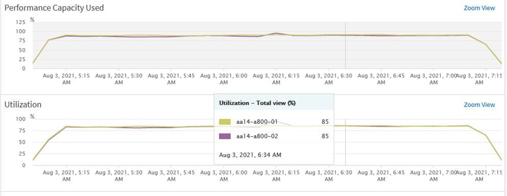
NetApp controller utilization during the high IOPS test
Infrastructure management with the Cisco Intersight platform
The Cisco Intersight cloud-based infrastructure management platform is delivered as a service with embedded analytics for your Cisco and third-party IT infrastructure. This platform offers an intelligent level of management that enables IT organizations to analyze, simplify, and automate their environments that are geographical dispersed around the world through a single management interface pane.
NetApp storage and VMware vSphere integration with the Cisco Intersight platform
The Cisco Intersight platform supports the management and monitoring of third-party infrastructures such as VMware vSphere clusters and NetApp storage. These third-party devices are integrated into the Cisco Intersight platform using a virtual appliance called Cisco Intersight Assist. For information about how to deploy the Cisco Intersight Assist virtual appliance, see Cisco Intersight Assist Getting Started Guide - Overview of Cisco Intersight Assist [Cisco Intersight] - Cisco.
To monitor and manage NetApp storage, you need to claim the NetApp Active IQ Unified Module (or AIQUM) and ONTAP cluster using Cisco Intersight Assist. After both targets are claimed through Cisco Intersight Assist, the NetApp storage array can be monitored and managed from the Cisco Intersight platform. All inventory of the NetApp storage array can be viewed by navigating through the appropriate components of the NetApp array. For instance, Figure 67 shows the logical interfaces of the SQL-SVM SVM created for this reference architecture validation.
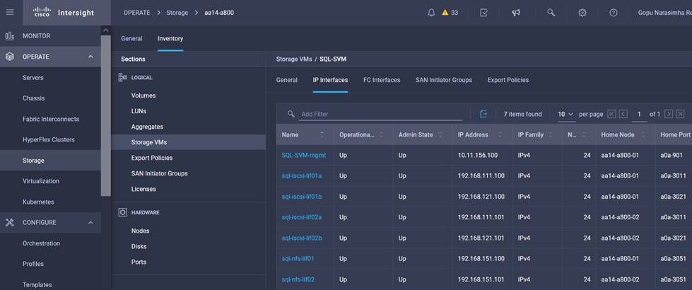
NetApp storage virtual machine inventory details in the Cisco Intersight platform
You can monitor and manage vSphere clusters from the Cisco Intersight platform by claiming the vCenter through the Cisco Intersight Assist appliance. After the vCenter is claimed, all inventory of the vSphere clusters managed by the vCenter can be viewed by navigating through the appropriate components of the vSphere clusters. Figure 68 shows the ESXi hosts used for this validation.
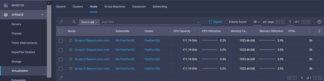
VMware vCenter vSphere cluster inventory details in the Cisco Intersight platform
Workflows to automate typical data center tasks
The Cisco Intersight orchestration engine enables users to implement automation for their most common provisioning tasks and create compound workflows for multiple and diverse targets to deliver end-to-end service. For instance, Figure 69 shows a workflow designed to create a NetApp SVM, define the logical Interfaces for the SVM, create a volume, map the volume to an initiator group, create a datastore, and create a guest virtual machine from a template on the newly created datastore.
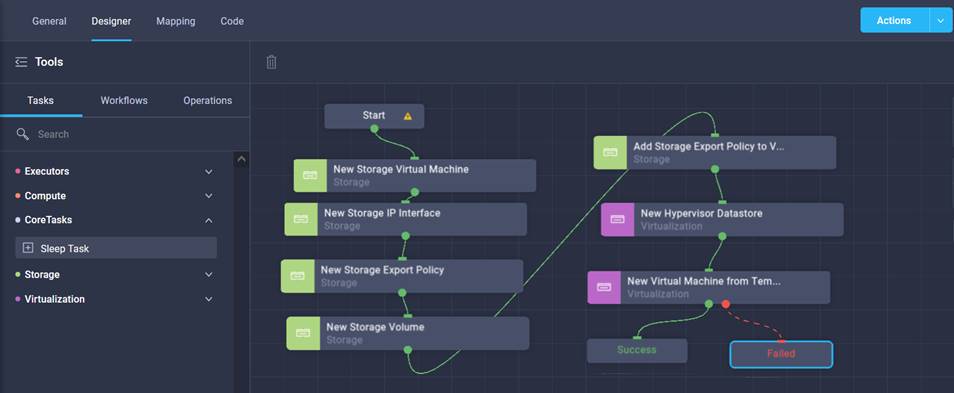
Cisco Intersight workflows to automate data center tasks
For more information about the Cisco Intersight orchestration engine, see the following resources:
● https://intersight.com/help/saas/resources/Workflow_Designer
FlexPod is the optimal shared infrastructure foundation for deploying a variety of IT workloads. It is built on leading computing, networking, storage, and infrastructure software components. The FlexPod reference architecture discussed in this document is built with Cisco UCS B200 M6 blades powered by 3rd Gen Intel Scalable processors and an NetApp AFF A800 storage array with the ONTAP 9.8 OS. It delivers the low-latency, consistent, and scalable database performance required by critical enterprise database workloads. With the NetApp SnapCenter data manageability tool, customers can capture application-consistent storage snapshots, avoiding the challenge of backup windows and gaining the capability to dynamically provision Dev/Test and business-continuity environments.
FlexPod provides highly efficient data lifecycle management and exceptional storage efficiency for SQL Server databases and logs. The performance tests detailed in this document demonstrate the robustness of the solution for hosting I/O-sensitive applications such as Microsoft SQL Server for database consolidation and peak storage I/O use cases.
Consult the following references for additional information about the topics discussed in this document.
Products and solutions
● Cisco Unified Computing System:
http://www.cisco.com/en/US/products/ps10265/index.html
● Cisco UCS 6454 Fabric Interconnect:
https://www.cisco.com/c/en/us/products/collateral/servers-unified-computing/datasheet-c78-741116.html
● Cisco UCS 5100 Series Blade Server Chassis:
http://www.cisco.com/en/US/products/ps10279/index.html
● Cisco UCS B-Series Blade Servers:
http://www.cisco.com/en/US/partner/products/ps10280/index.html
● https://www.cisco.com/c/dam/en/us/products/collateral/servers-unified-computing/ucs-b-series-blade-servers/b200m6-specsheet.pdf
● Cisco UCS adapters:
http://www.cisco.com/en/US/products/ps10277/prod_module_series_home.html
● Cisco UCS Manager:
http://www.cisco.com/en/US/products/ps10281/index.html
● Cisco Nexus 9000 Series Switches:
http://www.cisco.com/c/en/us/products/switches/nexus-9000-series-switches/index.html
● NetApp ONTAP 9:
http://www.netapp.com/us/products/platform-os/ontap/index.aspx
● NetApp AFF A800:
http://www.netapp.com/us/products/storage-systems/all-flash-array/aff-a-series.aspx
● Cisco UCS Hardware Compatibility Matrix:
https://ucshcltool.cloudapps.cisco.com/public/
● NetApp Interoperability Matrix Tool:
http://support.netapp.com/matrix/