FlexPod Datacenter for Microsoft SQL Server 2019 and VMware vSphere 6.7
Available Languages
Bias-Free Language
The documentation set for this product strives to use bias-free language. For the purposes of this documentation set, bias-free is defined as language that does not imply discrimination based on age, disability, gender, racial identity, ethnic identity, sexual orientation, socioeconomic status, and intersectionality. Exceptions may be present in the documentation due to language that is hardcoded in the user interfaces of the product software, language used based on RFP documentation, or language that is used by a referenced third-party product. Learn more about how Cisco is using Inclusive Language.
- US/Canada 800-553-2447
- Worldwide Support Phone Numbers
- All Tools
 Feedback
 Feedback

FlexPod Datacenter for Microsoft SQL Server 2019 and VMware vSphere 6.7
Deployment Guide for FlexPod Hosting Microsoft SQL Server 2019 Databases Running on Windows Server 2019 Guest Virtual Machines on VMware ESXi 6.7 U3
Published: July 2020

In partnership with:

About the Cisco Validated Design Program
The Cisco Validated Design (CVD) program consists of systems and solutions designed, tested, and documented to facilitate faster, more reliable, and more predictable customer deployments. For more information, go to:
http://www.cisco.com/go/designzone.
ALL DESIGNS, SPECIFICATIONS, STATEMENTS, INFORMATION, AND RECOMMENDATIONS (COLLECTIVELY, "DESIGNS") IN THIS MANUAL ARE PRESENTED "AS IS," WITH ALL FAULTS. CISCO AND ITS SUPPLIERS DISCLAIM ALL WARRANTIES, INCLUDING, WITHOUT LIMITATION, THE WARRANTY OF MERCHANTABILITY, FITNESS FOR A PARTICULAR PURPOSE AND NONINFRINGEMENT OR ARISING FROM A COURSE OF DEALING, USAGE, OR TRADE PRACTICE. IN NO EVENT SHALL CISCO OR ITS SUPPLIERS BE LIABLE FOR ANY INDIRECT, SPECIAL, CONSEQUENTIAL, OR INCIDENTAL DAMAGES, INCLUDING, WITHOUT LIMITATION, LOST PROFITS OR LOSS OR DAMAGE TO DATA ARISING OUT OF THE USE OR INABILITY TO USE THE DESIGNS, EVEN IF CISCO OR ITS SUPPLIERS HAVE BEEN ADVISED OF THE POSSIBILITY OF SUCH DAMAGES.
THE DESIGNS ARE SUBJECT TO CHANGE WITHOUT NOTICE. USERS ARE SOLELY RESPONSIBLE FOR THEIR APPLICATION OF THE DESIGNS. THE DESIGNS DO NOT CONSTITUTE THE TECHNICAL OR OTHER PROFESSIONAL ADVICE OF CISCO, ITS SUPPLIERS OR PARTNERS. USERS SHOULD CONSULT THEIR OWN TECHNICAL ADVISORS BEFORE IMPLEMENTING THE DESIGNS. RESULTS MAY VARY DEPENDING ON FACTORS NOT TESTED BY CISCO.
CCDE, CCENT, Cisco Eos, Cisco Lumin, Cisco Nexus, Cisco StadiumVision, Cisco TelePresence, Cisco WebEx, the Cisco logo, DCE, and Welcome to the Human Network are trademarks; Changing the Way We Work, Live, Play, and Learn and Cisco Store are service marks; and Access Registrar, Aironet, AsyncOS, Bringing the Meeting To You, Catalyst, CCDA, CCDP, CCIE, CCIP, CCNA, CCNP, CCSP, CCVP, Cisco, the Cisco Certified Internetwork Expert logo, Cisco IOS, Cisco Press, Cisco Systems, Cisco Systems Capital, the Cisco Systems logo, Cisco Unified Computing System (Cisco UCS), Cisco UCS B-Series Blade Servers, Cisco UCS C-Series Rack Servers, Cisco UCS S-Series Storage Servers, Cisco UCS Manager, Cisco UCS Management Software, Cisco Unified Fabric, Cisco Application Centric Infrastructure, Cisco Nexus 9000 Series, Cisco Nexus 7000 Series. Cisco Prime Data Center Network Manager, Cisco NX-OS Software, Cisco MDS Series, Cisco Unity, Collaboration Without Limitation, EtherFast, EtherSwitch, Event Center, Fast Step, Follow Me Browsing, FormShare, GigaDrive, HomeLink, Internet Quotient, IOS, iPhone, iQuick Study, LightStream, Linksys, MediaTone, MeetingPlace, MeetingPlace Chime Sound, MGX, Networkers, Networking Academy, Network Registrar, PCNow, PIX, PowerPanels, ProConnect, ScriptShare, SenderBase, SMARTnet, Spectrum Expert, StackWise, The Fastest Way to Increase Your Internet Quotient, TransPath, WebEx, and the WebEx logo are registered trademarks of Cisco Systems, Inc. and/or its affiliates in the United States and certain other countries.
All other trademarks mentioned in this document or website are the property of their respective owners. The use of the word partner does not imply a partnership relationship between Cisco and any other company. (0809R)
© 2020 Cisco Systems, Inc. All rights reserved.
© 2020 NetApp, Inc. All rights reserved.
Table of Contents
SQL Server or Enterprise Database Requirements from Infrastructure
FlexPod: Cisco and NetApp Verified and Validated Architecture
Out-of-the-Box Infrastructure High Availability
Cisco Unified Computing System
Cisco UCS Fabric Interconnects
Cisco UCS 5108 Blade Server Chassis
Cisco UCS B200 M5 Blade Server
Cisco Nexus 9336C-FX2 Switches
Microsoft SQL Server Database Storage Layout with SnapCenter
Cisco UCS Manager Configuration
NetApp Management Tools Setup and Configuration
Virtual Storage Console (VSC) 9.7
NetApp Storage Configuration for Windows VMs on ESXi and SQL Databases
Create Storage Virtual Machine (SVM) for SQL Workload
Create Load-Sharing Mirrors of SVM Root Volume
Storage for SQL Server Databases
Create FlexVol Volumes for SQL Database and Logs
Create SQL Database and Log LUNs
Create Storage Volumes for Windows Virtual Machines (ESXi Datastore)
VMware ESXi Host Configuration
ESXi Host Networking Configuration
Verifying ESXi Host NetQueue Feature
ESXi Host Logical Network Diagram
Creating and Deploying Virtual Machines for Hosting SQL Server Databases
Installing Guest Operating System
Storage Configuration Inside SQL Virtual Machines
Installing SQL Server and Configuration Recommendations
SnapCenter Configuration for SQL Database Backup, Restore, Cloning and Protection
Add Hosts (Windows VMs) to SnapCenter
Provision Storage to Windows VMs using SnapCenter
Verify on Demand Backup of SQL Databases
Verify SQL Database Restore from Backup
Verify SQL Database Cloning from Backup
Solution Performance Testing and Validation
Performance Test Methodology and Results
Database Performance Scalability within Single Cisco UCS B200 M5 ESXi Host
Database Performance Scalability Across the 4x Node ESXi Cluster
Maximum IO Capacity Testing of NetApp AFF400 Storage Array
SQL Server Database Workload Monitoring with Cisco Workload Manager (CWOM)
CWOM Recommendations for Underutilized SQL Server Database Virtual Machines
CWOM Recommendations for Overutilized SQL Server Database Virtual Machines
Infrastructure Monitoring with Cisco Intersight
It is important that a datacenter solution embrace technology advancement in various areas, such as compute, network, and storage technologies to address rapidly changing requirements and challenges of IT organizations. The current industry trend in datacenter design is towards shared infrastructures. By using virtualization along with pre-validated IT platforms, enterprise customers have embarked on the journey to the cloud by moving away from application silos and toward shared infrastructure that can be quickly deployed, thereby increasing agility, and reducing costs. Cisco and NetApp have partnered to deliver FlexPod, which uses best of breed storage, server, and network components to serve as the foundation for a variety of workloads, enabling efficient architectural designs that can be quickly and confidently deployed.
This document describes a FlexPod reference architecture using the latest hardware and software products and provides deployment recommendations for hosting Microsoft SQL Server 2019 databases in VMware ESXi virtualized environments. This solution also uses Cisco Workload Optimization Manager (CWOM) which provides automated recommendations for optimal and efficient resource utilization both for SQL workloads and infrastructure.
The solution is built on Cisco Unified Computing System (Cisco UCS) using the unified software release 4.1.1c to support the Cisco UCS hardware platforms including Cisco UCS B-Series Blade Servers, Cisco UCS 6400 Fabric Interconnects, Cisco Nexus 9000 Series Switches, and NetApp AFF Series Storage Arrays.
Introduction
The current IT industry is witnessing vast transformations in the datacenter solutions. In the recent years, there is a considerable interest towards pre-validated and engineered datacenter solutions. Introduction of virtualization technology in the key areas has impacted the design principles and architectures of these solutions in a big way. It has opened the doors for many applications running on bare metal systems to migrate to these new virtualized integrated solutions.
FlexPod System is one such pre-validated and engineered datacenter solution designed to address rapidly changing needs of IT organizations. Cisco and NetApp have partnered to deliver FlexPod, which uses best of breed compute, network and storage components to serve as the foundation for a variety of enterprise workloads including databases, ERP, CRM and Web applications, and so on.
The consolidation of IT applications, particularly databases, has generated considerable interest in the recent years. Being most widely adopted and deployed database platform over several years, Microsoft SQL Server databases have become the victim of a popularly known IT challenge “Database Sprawl.” Some of the challenges of SQL Server sprawl include underutilized Servers, wrong licensing, security concerns, management concerns, huge operational costs etc. Hence SQL Server databases would be right candidate for migrating and consolidating on to a more robust, flexible and resilient platform. This document discusses a FlexPod reference architecture for deploying and consolidating SQL Server databases.
Audience
The audience for this document includes, but is not limited to; sales engineers, field consultants, database administrators, professional services, IT managers, partner engineers, and customers who want to take advantage of an infrastructure built to deliver IT efficiency and enable IT innovation. It is expected that the reader should have prior knowledge on FlexPod Systems and its components.
Purpose of this Document
This document describes a FlexPod reference architecture and step-by-step implementation guidelines for deploying Microsoft SQL Server 2019 databases on FlexPod system.
![]() The step-by-step process to deploy and configure the FlexPod system is not in the scope of this document. For detailed instruction for deploying FlexPod Systems, refer to: FlexPod Datacenter with NetApp ONTAP 9.7, Cisco Intersight, and VMware vSphere 6.7 U3 CVD.
The step-by-step process to deploy and configure the FlexPod system is not in the scope of this document. For detailed instruction for deploying FlexPod Systems, refer to: FlexPod Datacenter with NetApp ONTAP 9.7, Cisco Intersight, and VMware vSphere 6.7 U3 CVD.
Highlights of this Solution
The following software and hardware products distinguish the reference architecture from previous releases:
· Microsoft SQL Server 2019 deployment on Windows Server 2019 Guest VMs running on VMWare vSphere 6.7 U3 Cluster.
· Support for the Cisco UCS 4.1(1) unified software release and Cisco UCS B200-M5 with 2nd Generation Intel Xeon Scalable Processors, and Cisco 1400 Series Virtual Interface Cards (VICs).
· Support for the latest Cisco UCS 6454 Fabric Interconnects and Cisco UCS 2408 Fabric Extender
· 100 Gigabit per second Ethernet Connectivity.
· NetApp All Flash A400 storage with Data ONTAP 9.7 and NetApp SnapCenter 4.3 for virtual machine and SQL Database backup and recovery.
· NetApp Virtual Storage Console Plug-in (VSC 9.7) for datastores storage provisioning to ESXi hosts.
· NetApp SnapCenter 4.3 for Virtual Machine backup and recovery.
· NetApp SnapCenter 4.3 for SQL Database Backup, Recovery, Protection and Cloning.
· NetApp SnapCenter 4.3 for storage provisioning to Windows VM for SQL Database and Log files.
· In-Guest software iSCSI storage connectivity for SQL Server database volumes.
· Cisco Intersight Software as a Service (SaaS) for UCS infrastructure monitoring.
· Cisco Workload Optimization Manager (CWOM) for monitoring SQL Server resource utilization and cost optimizations.
SQL Server or Enterprise Database Requirements from Infrastructure
This section details the key requirements for an enterprise database workload for your infrastructure. The following sections describe how each component used in the FlexPod infrastructure meets and exceeds the requirements of storing and running the enterprise workload and data.
Some of the key requirements are as follows:
· Highly available infrastructure: Infrastructure should be able to sustain failure of any Hardware or Software component.
· Accessibility and Predictable Performance: Infrastructure should allow access to workload data to set and meet variable level of performance Quality of Service.
· Scalability and Migration: As performance and capacity requirement of the database workload changes, ability to scale or migrate to optimal compute and storage tier within the infrastructure is very important.
· Storage Efficiency: Amount of data never goes down, and growth of duplicate data and multiple backups is fast. So, infrastructure capable of requiring less physical storage than actual data is critical in reducing TCO.
· Easy and Efficient Data Lifecycle Management: Data requires regular backups, quick restore, fast cloning, protection for disaster recovery, and archival. Infrastructure along with provided management tools, should be capable of handling these activities without extensive training, manual intervention, downtime, or extended maintenance duration.
· Security: Infrastructure should be capable of hosting workload for multiple tenants (business organizations), with appropriate access control, and encryption of data.
FlexPod System Overview
FlexPod is a best practice datacenter infrastructure architecture that includes these components:
· Cisco Unified Computing System
· Cisco Nexus Switches
· NetApp FAS or AFF storage, NetApp E-Series storage systems
These components are connected and configured according to the best practices of Cisco and NetApp and provide the ideal platform for running multiple enterprise workloads with confidence. The reference architecture explained in this document leverages the Cisco Nexus 9000 series switch. One of the key benefits of FlexPod is the ability to maintain consistency at scaling, including scale-up and scale-out. Each of the component families shown in Figure 7 (Cisco Unified Computing System, Cisco Nexus, and NetApp storage systems) offers platform and resource options to scale the infrastructure up or down, while supporting the same features and functionality that are required under the configuration and connectivity best practices of FlexPod.
FlexPod Benefits
As customers transition toward shared infrastructure or cloud computing, they face several challenges such as initial transition hiccups, return on investment (ROI) analysis, infrastructure management and future growth plans. By introducing standardization, FlexPod helps customers mitigate the risk and uncertainty involved in planning, designing, and implementing a new datacenter infrastructure. The result is a more predictive and adaptable architecture capable of meeting and exceeding customers' IT demands.
The following list provides the unique features and benefits that the FlexPod system provides for consolidating SQL Server database deployments:
· Support for Intel Xeon 2nd generation scalable family CPUs, Cisco UCS B200 M5 blades enables consolidating more SQL Server virtual machines and thereby achieving higher consolidation ratios reducing Total Cost of Ownership and achieving quick ROIs.
· 100 Gigabit Ethernet connectivity and storage connectivity using Cisco UCS 4th generation Fabric Interconnects, Cisco Nexus 9000 series switches, and NetApp AFF A400 storage Arrays.
· Nondisruptive policy-based management of infrastructure using Cisco UCS Manager.
· Fast IO performance using NetApp All Flash Storage Arrays and Complete virtual machine protection by using NetApp Snapshot technology and direct storage access to SQL virtual machines using in-guest iSCSI Initiator.
· Resource utilization reports and cost optimization recommendations with Cisco Workload Optimization manager.
FlexPod: Cisco and NetApp Verified and Validated Architecture
Cisco and NetApp have thoroughly validated and verified the FlexPod solution architecture and its many use cases while creating a portfolio of detailed documentation, information, and references to assist customers in transforming their datacenters to this shared infrastructure model. This portfolio includes, but is not limited to the following items:
· Best practice architectural design
· Workload sizing and scaling guidance
· Implementation and deployment instructions
· Technical specifications (rules for FlexPod configuration do's and don’ts)
· Frequently asked questions (FAQs)
· Cisco Validated Designs and NetApp Verified Architectures (NVAs) focused on several use cases
Cisco and NetApp have also built a robust and experienced support team focused on FlexPod solutions, from customer accounts and technical sales representatives, to professional services and technical support engineers. The cooperative support program extended by Cisco and NetApp provides customers and channel service partners with direct access to technical experts who collaborate with cross vendors and have access to shared lab resources to resolve potential issues. FlexPod supports tight integration with virtualized cloud infrastructures, making it a logical choice for a long-term investment. The following IT initiatives are addressed by the FlexPod solution.
Integrated System
FlexPod is a pre-validated infrastructure that brings together compute, storage, and network to simplify, accelerate, and minimize the risk associated with datacenter builds and application rollouts. These integrated systems provide a standardized approach in the datacenter that facilitates staff expertise, application onboarding, and automation as well as operational efficiencies relating to compliance and certification.
Out-of-the-Box Infrastructure High Availability
FlexPod is a highly available and scalable infrastructure that IT can evolve over time to support multiple physical and virtual application workloads. FlexPod has no single point of failure at any level, from the server through the network, to storage. The fabric is fully redundant and scalable, and provides seamless traffic failover, should any individual component fail at the physical or virtual layer.
FlexPod Design Principles
FlexPod addresses four primary design principles:
· Application availability: Makes sure that services are accessible and ready to use
· Scalability: Addresses increasing demands with appropriate resources
· Flexibility: Provides new services or recovers resources without requiring infrastructure modifications
· Manageability: Facilitates efficient infrastructure operations through open standards and APIs
The following sections provide a brief introduction of the various hardware and software components used in this solution.
Cisco Unified Computing System
Cisco Unified Computing System (Cisco UCS) is a next-generation solution for blade and rack server computing. The system integrates a low-latency; lossless 10,25,40 or100 Gigabit Ethernet unified network fabric with enterprise-class, x86-architecture servers. The system is an integrated, scalable, multi-chassis platform in which all resources participate in a unified management domain. Cisco Unified Computing System accelerates the delivery of new services simply, reliably, and securely through end-to-end provisioning and migration support for both virtualized and non-virtualized systems. Cisco Unified Computing System provides:
· Comprehensive Management
· Radical Simplification
· High Performance
Cisco Unified Computing System consists of the following components:
· Compute - The system is based on an entirely new class of computing system that incorporates rack mount and blade servers based on Intel Xeon scalable processors product family.
· Network - The system is integrated onto a low-latency, lossless, 10/25/40/100-Gbps unified network fabric. This network foundation consolidates Local Area Networks (LANs), Storage Area Networks (SANs), and high-performance computing networks, which are separate networks today. The unified fabric lowers costs by reducing the number of network adapters, switches, and cables, and by decreasing the power and cooling requirements.
· Virtualization - The system unleashes the full potential of virtualization by enhancing the scalability, performance, and operational control of virtual environments. Cisco security, policy enforcement, and diagnostic features are now extended into virtualized environments to better support changing business and IT requirements.
· Storage access - The system provides consolidated access to both SAN storage and Network Attached Storage (NAS) over the unified fabric. It is also an ideal system for Software defined Storage (SDS). Combining the benefits of single framework to manage both the compute and Storage servers in a single pane, Quality of Service (QOS) can be implemented if needed to inject IO throttling in the system. In addition, the server administrators can pre-assign storage-access policies to storage resources, for simplified storage connectivity and management leading to increased productivity. In addition to external storage, both rack and blade servers have internal storage which can be accessed through built-in hardware RAID controllers. With storage profile and disk configuration policy configured in Cisco UCS Manager, storage needs for the host OS and application data gets fulfilled by user defined RAID groups for high availability and better performance.
· Management - the system uniquely integrates all system components to enable the entire solution to be managed as a single entity by Cisco UCS Manager. Cisco UCS Manager has an intuitive GUI, a CLI, and a powerful scripting library module for Microsoft PowerShell built on a robust API to manage all system configuration and operations.
Cisco Unified Computing System fuses access layer networking and servers. This high-performance, next-generation server system provides a data center with a high degree of workload agility and scalability.
Cisco UCS Manager
Cisco UCS Manager (UCSM) provides unified, embedded management for all software and hardware components in the Cisco UCS. Using Single Connect technology, it manages, controls, and administers multiple chassis for thousands of virtual machines. Administrators use the software to manage the entire Cisco Unified Computing System as a single logical entity through an intuitive GUI, CLI, or an XML API. Cisco UCS Manager resides on a pair of Cisco UCS 6300 Series Fabric Interconnects using a clustered, active-standby configuration for high availability.
Cisco UCS Manager offers unified embedded management interface that integrates server, network, and storage. Cisco UCS Manager performs auto-discovery to detect inventory, manage, and provision system components that are added or changed. It offers comprehensive set of XML API for third part integration, exposes 9000 points of integration and facilitates custom development for automation, orchestration, and to achieve new levels of system visibility and control.
Service profiles benefit both virtualized and non-virtualized environments and increase the mobility of non-virtualized servers, such as when moving workloads from server to server or taking a server offline for service or upgrade. Profiles can also be used in conjunction with virtualization clusters to bring new resources online easily, complementing existing virtual machine mobility.
For more information about Cisco UCS Manager, go to: https://www.cisco.com/c/en/us/products/servers-unified-computing/ucs-manager/index.html
Cisco UCS Fabric Interconnects
The Fabric interconnects provide a single point for connectivity and management for the entire system. Typically deployed as an active-active pair, the system’s fabric interconnects integrate all components into a single, highly-available management domain controlled by Cisco UCS Manager. The fabric interconnects manage all I/O efficiently and securely at a single point, resulting in deterministic I/O latency regardless of a server or virtual machine’s topological location in the system.
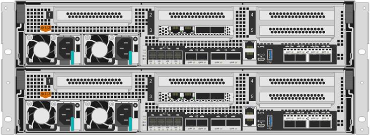
Cisco UCS 6400 series product family supports low-latency, lossless 10/25/40/100 Gigabit Ethernet unified network fabric capabilities, which increase the reliability, efficiency, and scalability of Ethernet networks. The fabric interconnect supports multiple traffic classes over a lossless Ethernet fabric from the server through the fabric interconnect. Significant TCO savings come from an FCoE-optimized server design in which Network Interface Cards (NICs), Host Bus Adapters (HBAs), cables, and switches can be consolidated. The Cisco UCS 6454 is a 1-RU Fabric Interconnect that features 10/25/40/100 Gigabit Ethernet, FCoE, and Fibre Channel switch offering up to 3.82 Tbps throughput and up to 54 ports. The switch has 28 10/25-Gbps Ethernet ports, 4 1/10/25- Gbps Ethernet ports, 6 40/100-Gbps Ethernet uplink ports, and 16 unified ports that can support 10/25-Gbps Ethernet ports or 8/16/32-Gbps Fibre Channel ports. All Ethernet ports are capable of supporting FCoE.
Figure 1 Cisco UCS Fabric Interconnect 6454
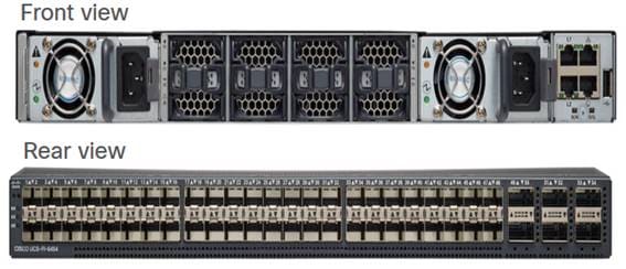
For more information, go to: https://www.cisco.com/c/en/us/products/collateral/servers-unified-computing/datasheet-c78-741116.html
Cisco UCS 5108 Blade Server Chassis
The Cisco UCS 5100 Series Blade Server Chassis is a crucial building block of the Cisco Unified Computing System, delivering a scalable and flexible blade server chassis. The Cisco UCS 5108 Blade Server Chassis is six rack units (6RU) high and can mount in an industry-standard 19-inch rack. A single chassis can house up to eight half-width Cisco UCS B-Series Blade Servers and can accommodate both half-width and full-width blade form factors. Four single-phase, hot-swappable power supplies are accessible from the front of the chassis. These power supplies are 92 percent efficient and can be configured to support non-redundant, N+ 1 redundant and grid-redundant configurations. The rear of the chassis contains eight hot-swappable fans, four power connectors (one per power supply), and two I/O bays for Cisco UCS 2408 Fabric Extenders. A passive mid-plane provides connectivity between blade serves and fabric interconnects.
For more information, go to: http://www.cisco.com/c/en/us/products/servers-unified-computing/ucs-5100-series-blade-server-chassis/index.html
Cisco UCS Fabric Extenders
The Cisco UCS 2408 Fabric Extender brings the unified fabric into the blade server enclosure, providing connectivity between the blade servers and the fabric interconnect, simplifying diagnostics, cabling, and management. It is a fourth-generation I/O Module (IOM) that shares the same form factor as the third-generation Cisco UCS 2304 Fabric Extender, which is compatible with the Cisco UCS 5108 Blade Server Chassis.
The Cisco UCS 2408 connects the I/O fabric between the Cisco UCS 6454 Fabric Interconnect and the Cisco UCS 5100 Series Blade Server Chassis, enabling a lossless and deterministic converged fabric to connect all blades and chassis together. Because the fabric extender is similar to a distributed line card, it does not perform any switching and is managed as an extension of the fabric interconnects. This approach removes switching from the chassis, reducing overall infrastructure complexity and enabling Cisco UCS to scale to many chassis without multiplying the number of switches needed, reducing TCO, and allowing all chassis to be managed as a single, highly available management domain.
The Cisco UCS 2408 Fabric Extender has eight 25-Gigabit Ethernet, FCoE-capable, Small Form-Factor Pluggable (SFP28) ports that connect the blade chassis to the fabric interconnect. Each Cisco UCS 2408 provides 10-Gigabit Ethernet ports connected through the midplane to each half-width slot in the chassis, providing a total of 32 10G interfaces to Cisco UCS blade servers. Typically configured in pairs for redundancy, two fabric extenders provide up to 400 Gbps of I/O from Cisco UCS FI 6400 series to Cisco UCS 5108 chassis.
Figure 2 Cisco UCS 2408 Fabric Extender
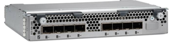
For more information, go to: https://www.cisco.com/c/en/us/products/collateral/servers-unified-computing/datasheet-c78-742624.html
Cisco UCS B200 M5 Blade Server
The Cisco UCS B200 M5 Blade Server delivers performance, flexibility, and optimization for deployments in data centers, in the cloud, and at remote sites. This enterprise-class server offers market-leading performance, versatility, and density without compromise for workloads including Virtual Desktop Infrastructure (VDI), web infrastructure, distributed databases, converged infrastructure, and enterprise applications such as Oracle and SAP HANA. The Cisco UCS B200 M5 Blade Server can quickly deploy stateless physical and virtual workloads through programmable, easy-to-use Cisco UCS Manager Software and simplified server access through Cisco SingleConnect technology. The Cisco UCS B200 M5 Blade Server is a half-width blade with up to eight servers and can reside in the 6-Rack-Unit (6RU) Cisco UCS 5108 Blade Server Chassis, offering one of the highest densities of servers per rack unit of blade chassis in the industry. You can configure the Cisco UCS B200 M5 to meet your local storage requirements without having to buy, power, and cool components that you do not need. The Cisco UCS B200 M5 Blade Server provides these main features:
· Up to two Intel Xeon 2nd generation Scalable CPUs with up to 28 cores per CPU.
· Up to 24 DDR4 DIMMs at 2933 MHz for improved performance and 12 DIMM slots can be repurposed for Intel Optane™ DC Persistent Memory. Support up to 3 TB of total memory when using 128-GB DIMMs.
· Modular LAN On Motherboard (mLOM) card with Cisco UCS Virtual Interface Card (VIC) 1440, a single-port 40-Gbps or 4x10-Gbps Gigabit Ethernet, Fibre Channel over Ethernet (FCoE)–capable mLOM mezzanine adapter.
· Optional rear mezzanine VIC with a single-port 40-Gbps or 4x10-Gbps unified I/O ports.
· Two optional, hot-pluggable, Hard-Disk Drives (HDDs), Solid-State Disks (SSDs), or NVMe 2.5-inch drives with a choice of enterprise-class RAID or pass-through controllers.
Figure 3 Cisco UCS B200 M5 Blade Server
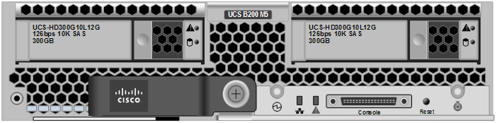
For more information, go to: https://www.cisco.com/c/en/us/products/collateral/servers-unified-computing/ucs-b-series-blade-servers/datasheet-c78-739296.html
Cisco VIC Interface Cards
Cisco UCS VIC1440 is a single-port 40-Gbps or 4x10-Gbps Ethernet/FCoE capable modular LAN On Motherboard (mLOM) designed exclusively for the M5 generation of Cisco UCS B-Series Blade Servers. When used in combination with an optional port expander, the Cisco UCS VIC 1440 capabilities are enabled for two ports of 40-Gbps Ethernet. The Cisco UCS VIC 1440 enables a policy-based, stateless, agile server infrastructure that can present to the host PCIe standards-compliant interfaces that can be dynamically configured as either NICs or HBAs.
For more information, go to: https://www.cisco.com/c/en/us/products/collateral/interfaces-modules/unified-computing-system-adapters/datasheet-c78-741130.html
Cisco UCS Differentiators
Cisco Unified Computing System is revolutionizing the way servers are managed in the datacenter. The following are the unique differentiators of Cisco UCS and Cisco UCS Manager:
· Embedded Management—In Cisco UCS, the servers are managed by the embedded firmware in the Fabric Interconnects, eliminating need for any external physical or virtual devices to manage the servers.
· Unified Fabric—In Cisco UCS, from blade server chassis or rack servers to FI, there is a single Ethernet cable used for LAN, SAN and management traffic. This converged I/O results in reduced cables, SFPs and adapters which in turn reduce capital and operational expenses of the overall solution.
· Auto Discovery—By simply inserting the blade server in the chassis or connecting rack server to the fabric interconnect, discovery and inventory of compute resource occurs automatically without any management intervention. The combination of unified fabric and auto-discovery enables the wire-once architecture of Cisco UCS, where its compute capability can be extended easily while keeping the existing external connectivity to LAN, SAN and management networks.
· Policy Based Resource Classification—When a compute resource is discovered by Cisco UCS Manager, it can be automatically classified to a given resource pool based on policies defined. This capability is useful in multi-tenant cloud computing. This CVD showcases the policy-based resource classification of Cisco UCS Manager.
· Combined Rack and Blade Server Management—Cisco UCS Manager can manage B-Series blade servers and C-Series rack server under the same Cisco UCS domain. This feature, along with stateless computing makes compute resources truly hardware form factor agnostic.
· Model-based Management Architecture—Cisco UCS Manager Architecture and management database is model based and data driven. An open XML API is provided to operate on the management model. This enables easy and scalable integration of Cisco UCS Manager with other management systems.
· Policies, Pools, Templates—The management approach in Cisco UCS Manager is based on defining policies, pools and templates, instead of cluttered configuration, which enables a simple, loosely coupled, data driven approach in managing compute, network and storage resources.
· Loose Referential Integrity—In Cisco UCS Manager, a service profile, port profile or policies can refer to other policies or logical resources with loose referential integrity. A referred policy cannot exist at the time of authoring the referring policy or a referred policy can be deleted even though other policies are referring to it. This provides different subject matter experts to work independently from each-other. This provides great flexibility where different experts from different domains, such as network, storage, security, server and virtualization work together to accomplish a complex task.
· Policy Resolution—In Cisco UCS Manager, a tree structure of organizational unit hierarchy can be created that mimics the real-life tenants and/or organization relationships. Various policies, pools and templates can be defined at different levels of organization hierarchy. A policy referring to another policy by name is resolved in the organization hierarchy with closest policy match. If no policy with specific name is found in the hierarchy of the root organization, then special policy named “default” is searched. This policy resolution practice enables automation friendly management APIs and provides great flexibility to owners of different organizations.
· Service Profiles and Stateless Computing—a service profile is a logical representation of a server, carrying its various identities and policies. This logical server can be assigned to any physical compute resource as far as it meets the resource requirements. Stateless computing enables procurement of a server within minutes, which used to take days in legacy server management systems.
· Built-in Multi-Tenancy Support—The combination of policies, pools and templates, loose referential integrity, policy resolution in organization hierarchy and a service profiles based approach to compute resources makes Cisco UCS Manager inherently friendly to multi-tenant environment typically observed in private and public clouds.
· Extended Memory—the enterprise-class Cisco UCS B200 M5 blade server extends the capabilities of Cisco’s Unified Computing System portfolio in a half-width blade form factor. The Cisco UCS B200 M5 harnesses the power of the latest Intel Xeon scalable processors product family CPUs with up to 3 TB of RAM– allowing huge virtual machine-to-physical server ratio required in many deployments or allowing large memory operations required by certain architectures like Big-Data.
· Virtualization Aware Network—VM-FEX technology makes the access network layer aware about host virtualization. This prevents domain pollution of compute and network domains with virtualization when virtual network is managed by port-profiles defined by the network administrators’ team. VM-FEX also off-loads hypervisor CPU by performing switching in the hardware, thus allowing hypervisor CPU to do more virtualization related tasks. VM-FEX technology is well integrated with VMware vCenter, Linux KVM and Hyper-V SR-IOV to simplify cloud management.
· Simplified QoS—Even though Fiber Channel and Ethernet are converged in Cisco UCS fabric, built-in support for QoS and lossless Ethernet makes it seamless. Network Quality of Service (QoS) is simplified in Cisco UCS Manager by representing all system classes in one GUI panel.
Cisco Nexus 9336C-FX2 Switches
In this solution, the Cisco Nexus 9336C-FX2 switches are used as upstream switches. It offers 36 40/100 Gigabit Ethernet QSFP+ ports. All ports are line rate, delivering 7.2 Tbps of throughput with a latency of less than 2 micro seconds in a 1-rack-unit (1RU) form factor.
Figure 4 Cisco UCS Nexus 9336C-FX2
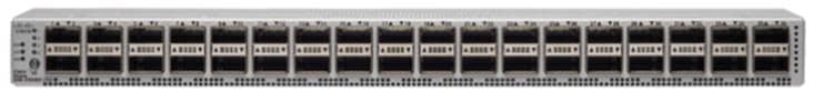
For more information, go to: https://www.cisco.com/c/en/us/products/switches/nexus-9336c-fx2-switch/index.html
NetApp AFF A400 Storage
With the new A-Series All Flash FAS (AFF) controller lineup, NetApp provides industry leading performance while continuing to provide a full suite of enterprise-grade data management and data protection features. The A-Series lineup offers double the IOPS, while decreasing the latency.
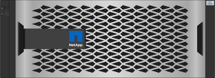
This solution utilizes the NetApp AFF A400. This controller provides high performance benefits of 40/100GbE and all flash SSDs, while taking up only 5U of rack space. Configured with 24 x 1.9TB SSD, the A400 provides ample performance and over 60TB effective capacity. This makes it an ideal controller for a shared workload converged infrastructure. For situations where more performance is needed, the A800s would be better fit.
Figure 5 NetApp AFF A400
A400 Specifications
The major specifications of the NetApp A400 All Flash Storage Systems are listed below. For more information, see: NetApp Hardware Universe.
· OS and Data Management
- ONTAP OS runs on the platform and manages data, and serves data to workloads running in FlexPod environment
· Storage
- NVMe SED, non-SED, and NSE SSDs,
- SAS NSE or non-NSE SSDs
- Maximum Raw Capacity of 14688 TB from 480 30.6TB drives
· Storage Protocols: Multiple protocols support on the same platform
- NAS (File): CIFS and NFS
- SAN (Block): iSCSI and FCP
· IOPS and Latency: (per HA pair)
- Maximum 400K IOPS with 100% 8K random read at 0.4ms latency
- 13GB/s Throughput for FCP sequential read
· Form factor: 4U
· Processor and memory (per high availability pair)
- CPU cores: 40
- Memory: 256GB
- NVDIMM: 32GB
· Onboard I/O ports (per controller)
- 2x QSFP28 (100GbE RoCE): NVMe storage attachment
- 2x SFP28 (25GbE RoCE): HA
- 4x mini-SAS HD: External storage attachment
§ DS224C and DS2246 shelves supported
- Host IO access
§ Ethernet configuration: 4x SFP28 (25GbE RoCE)
§ Unified configuration: 4x SFP+ (16Gb FC)
- 5x PCIe expansion slots
§ Cluster network adapter present in PCIe slot 3 by default
- Maximum Nodes in a cluster: 24 for NAS and 12 for SAN
NetApp ONTAP 9.7
ONTAP 9.7 is the Operating System software for storage platforms and data management. ONTAP is used with the NetApp all-flash storage platforms in the solution design. ONTAP software offers unified storage for applications that read and write data over block or file-access protocols in storage configurations that range from high-speed flash to lower-priced spinning media or cloud-based object storage.
ONTAP implementations can run on NetApp engineered FAS or AFF appliances, on commodity hardware (ONTAP Select), and in private, public, or hybrid clouds (NetApp Private Storage and Cloud Volumes ONTAP). Specialized implementations offer best-in-class converged infrastructure as featured here as part of the FlexPod Datacenter solution and access to third-party storage arrays (NetApp FlexArray virtualization).
Together these implementations form the basic framework of the NetApp Data Fabric, with a common software-defined approach to data management and fast, efficient replication across platforms. FlexPod and ONTAP architectures can serve as the foundation for both hybrid cloud and private cloud designs.
The following sections provide an overview of how ONTAP 9.7 is an industry-leading data management software architected on the principles of software defined storage.
Heterogeneous Cluster
ONTAP 9.7 can run on multiple types of All flash, or FAS systems (with hybrid disks or spinning disks storage) and form a storage cluster. ONTAP 9.7 can also manage storage tier in cloud. Single storage ONTAP OS instance managing different storage tiers, makes efficient data tiering and workload optimization possible through single management realm.
NetApp Storage Virtual Machine
A NetApp ONTAP cluster serves data through at least one and possibly multiple storage virtual machines (SVMs; formerly called Vservers). An SVM is a logical abstraction that represents the set of physical resources of the cluster. Data volumes and network logical interfaces (LIFs) are created and assigned to an SVM and might reside on any node in the cluster to which the SVM has been given access. An SVM might own resources on multiple nodes concurrently, and those resources can be moved non-disruptively from one node in the storage cluster to another. For example, a NetApp FlexVol flexible volume can be non-disruptively moved to a new node and aggregate, or a data LIF can be transparently reassigned to a different physical network port. The SVM abstracts the cluster hardware, and thus it is not tied to any specific physical hardware.
An SVM can support multiple data protocols concurrently. Volumes within the SVM can be joined to form a single NAS namespace, which makes all SVM's data available through a single share or mount point to NFS and CIFS clients. SVMs also support block-based protocols, and LUNs can be created and exported by using iSCSI, FC, or FCoE. Any or all of these data protocols can be configured for use within a given SVM. Storage administrators and management roles can also be associated with SVM, which enables higher security and access control, particularly in environments with more than one SVM, when the storage is configured to provide services to different groups or set of workloads.
Storage Efficiencies
Storage efficiency has always been a primary architectural design point of ONTAP data management software. A wide array of features allows you to store more data using less space. In addition to deduplication and compression, you can store your data more efficiently by using features such as unified storage, multitenancy, thin provisioning, and utilize NetApp Snapshot technology.
Starting with ONTAP 9, NetApp guarantees that the use of NetApp storage efficiency technologies on AFF systems reduce the total logical capacity used to store customer data by 75 percent, a data reduction ratio of 4:1. This space reduction is enabled by a combination of several different technologies, including deduplication, compression, and compaction.
Compaction, which was introduced in ONTAP 9, is the latest patented storage efficiency technology released by NetApp. In the ONTAP WAFL file system, all I/O takes up 4KB of space, even if it does not actually require 4KB of data. Compaction combines multiple blocks that are not using their full 4KB of space together into one block. This one block can be more efficiently stored on the disk to save space.
Encryption
Data security continues to be an important consideration for customers purchasing storage systems. NetApp supported self-encrypting drives in storage clusters prior to ONTAP 9. However, in ONTAP 9, the encryption capabilities of ONTAP are extended by adding an Onboard Key Manager (OKM). The OKM generates and stores keys for each of the drives in ONTAP, allowing ONTAP to provide all functionality required for encryption out of the box. Through this functionality, sensitive data stored on disk is secure and can only be accessed by ONTAP.
Beginning with ONTAP 9.1, NetApp has extended the encryption capabilities further with NetApp Volume Encryption (NVE), a software-based mechanism for encrypting data. It allows a user to encrypt data at the per-volume level instead of requiring encryption of all data in the cluster, thereby providing more flexibility and granularity to the ONTAP administrators. This encryption extends to Snapshot copies and NetApp FlexClone volumes that are created in the cluster. One benefit of NVE is that it runs after the implementation of the storage efficiency features, and, therefore, it does not interfere with the ability of ONTAP to create space savings.
For more information about encryption in ONTAP, see the NetApp Power Encryption Guide in the NetApp ONTAP 9 Documentation Center.
FlexClone
NetApp FlexClone technology enables instantaneous cloning of a dataset without consuming any additional storage until cloned data differs from the original.
SnapMirror (Data Replication)
Quality of Service (QoS)
ONTAP allows to set Minimum, Maximum, and Adaptive QoS for workloads. Here are the details.
· QoS Max (also known as Limits)
Maximum performance level assigned to the storage object. This limits the amount of system resources that the workload can use. Often used to stop a workload from bullying/impacting other workloads. Max QoS can be set for SVM, Vol, LUN, File in ONTAP. It works by throttling throughput or IOPS at the network side.
· QoS Min (also known as Floors)
Minimum "guaranteed" performance level assigned to the storage object. Min QoS can be set for Vol, or LUN in ONTAP.
· Adaptive QoS
A dynamic QoS policy that maintains IOPS/TB ratio as storage size (used or provisioned) changes. Adaptive QoS policy lets performance (IOPS) scale automatically with storage capacity (TB). Adaptive QoS is can be set on volume.
· Service Level Management
Service level management is the management and monitoring of storage resources with respect to performance and capacity.
· Service Level Objective (SLO)
The key tenets of service level management. SLOs are defined by a service level agreement in terms of performance and capacity.
NetApp SnapCenter
SnapCenter is a NetApp next-generation data protection software for tier 1 enterprise applications. SnapCenter, with its single-pane-of-glass management interface, automates and simplifies the manual, complex, and time-consuming processes associated with the backup, recovery, and cloning of multiple databases and other application workloads.
SnapCenter leverages technologies, including NetApp Snapshot copies, SnapMirror replication technology, SnapRestore data recovery software, and FlexClone thin cloning technology, that allow it to integrate seamlessly with technologies offered by Oracle, Microsoft, SAP, VMware, and MongoDB across FC, iSCSI, and NAS protocols. This integration allows IT organizations to scale their storage infrastructure, meet increasingly stringent SLA commitments, and improve the productivity of administrators across the enterprise.
SnapCenter is used in this solution for the following use cases:
· Backup and restore of VMware virtual machines.
· Backup, restore, protection and cloning of SQL Databases.
· Storage provisioning for SQL databases and logs.
SnapCenter Architecture
SnapCenter is a centrally managed web-based application that runs on a Windows platform and remotely manages multiple servers that must be protected.
Figure 6 illustrates the high-level architecture of the NetApp SnapCenter Server.
Figure 6 SnapCenter Architecture
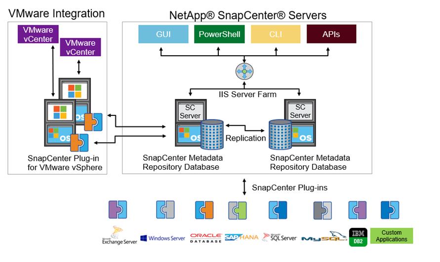
The SnapCenter Server has an HTML5-based GUI as well as PowerShell cmdlets and APIs.
The SnapCenter Server is high-availability capable out of the box, meaning that if one SnapCenter host is ever unavailable for any reason, then the second SnapCenter Server can seamlessly take over and no operations are affected.
The SnapCenter Server can push out plug-ins to remote hosts. These plug-ins are used to interact with an application, a database, or a file system. In most cases, the plug-ins must be present on the remote host so that application- or database-level commands can be issued from the same host where the application or database is running.
To manage the plug-ins and the interaction between the SnapCenter Server and the plug-in host, SnapCenter uses SM Service, which is a NetApp SnapManager web service running on top of Windows Server Internet Information Services (IIS) on the SnapCenter Server. SM Service takes all client requests such as backup, restore, clone, and so on.
The SnapCenter Server communicates those requests to SMCore, which is a service that runs co-located within the SnapCenter Server and remote servers and plays a significant role in coordinating with the SnapCenter plug-ins package for Windows. The package includes the SnapCenter plug-in for Microsoft Windows Server and SnapCenter plug-in for Microsoft SQL Server to discover the host file system, gather database metadata, quiesce and thaw, and manage the SQL Server database during backup, restore, clone, and verification.
SnapCenter Virtualization (SCV) is another plug-in that manages virtual servers running on VMWare and that helps in discovering the host file system, databases on virtual machine disks (VMDK), and raw device mapping (RDM).
SnapCenter Features
SnapCenter enables you to create application-consistent Snapshot copies and to complete data protection operations, including Snapshot copy-based backup, clone, restore, and backup verification operations. SnapCenter provides a centralized management environment, while using role-based access control (RBAC) to delegate data protection and management capabilities to individual application users across the SnapCenter Server and Windows hosts.
SnapCenter includes the following key features:
· A unified and scalable platform across applications and database environments and virtual and nonvirtual storage, powered by the SnapCenter Server.
· Consistency of features and procedures across plug-ins and environments, supported by the SnapCenter user interface.
· Role Based Access Control (RBAC) for security and centralized role delegation.
· Snapshot based application-consistent Backup, restore, clone, protection, and backup verification support from both primary and secondary destinations (NetApp SnapMirror and SnapVault).
· Remote package installation from the SnapCenter GUI.
· Nondisruptive, remote upgrades.
· A dedicated SnapCenter repository for backup catalog and faster data retrieval.
· Load balancing implemented by using Microsoft Windows network load balancing (NLB) and application request routing (ARR), with support for horizontal scaling.
· Centralized scheduling and policy management to support backup and clone operations.
· Centralized reporting, monitoring, and dashboard views.
· Backup, restore and data protection for VMware virtual machines, SQL Server Databases, Oracle Databases, MySQL, SAP HANA, MongoDB, and Microsoft Exchange.
· SnapCenter Plug-in for VMware in vCenter integration into the vSphere Web Client. All virtual machine backup and restore tasks are preformed through the web client GUI.
Using the SnapCenter Plug-in for SQL Server you can do the following:
· Create policies, resource groups and backup schedules for SQL Database.
· Backup SQL Databases and Logs.
· Restore SQL Databases (on Windows guest OS).
· Protect Database backup on secondary site for Disaster recovery.
· Protect Database backup on SnapVault for Archival
· Create Database clone.
· Provision storage to Windows VMs for SQL Databases and Logs.
· Monitor backup and data protection operations.
· Generate reports of backup and data protection operations.
· Support RBAC security and centralized role delegation .
· Generate dashboard and reports that provide visibility into protected versus unprotected databases and status of backup, restore, and mount jobs.
Using the SnapCenter Plug-in for VMware in vCenter you can do the following:
· Create policies, resource groups and backup schedules for virtual machines.
· Backup virtual machines, VMDKs, and datastores.
· Restore virtual machines, VMDKs, and files and folders (on Windows guest OS).
· Attach and detach VMDK.
· Monitor and report data protection operations on virtual machines and datastores.
· Support RBAC security and centralized role delegation.
· Support guest file or folder (single or multiple) support for Windows guest OS.
· Restore an efficient storage base from primary and secondary Snapshot copies through Single File SnapRestore.
· Generate dashboard and reports that provide visibility into protected versus unprotected virtual machines and status of backup, restore, and mount jobs.
· Attach or detach virtual disks from secondary Snapshot copies.
· Attach virtual disks to an alternate virtual machine.
Microsoft SQL Server Database Storage Layout with SnapCenter
SnapCenter best practice considerations for Microsoft SQL Server database layout are aligned with the suggested Microsoft SQL Server deployment. SnapCenter supports backup only of user databases that reside on a NetApp storage system. Along with the performance benefit of segregating user database layout into different volumes, SnapCenter also has a large influence on the time required to back up and restore. Separate volumes for data and log files significantly improve the restore time as compared to a single volume hosting multiple user data files. Similarly, user databases with I/O-intensive applications might experience increased backup time.
When backing-up databases with SnapCenter, take the following considerations into account:
· Databases with I/O intensive queries throughout the day should be isolated in different volumes and eventually have separate jobs to back them up.
· Large databases and databases that have minimal RTO should be placed in separate volumes for faster recovery.
· Small to medium-size databases that are less critical or that have fewer I/O requirements should be consolidated into a single volume. Backing up many databases residing in the same volume results in fewer Snapshot copies to be maintained. NetApp also recommends consolidating Microsoft SQL Server instances to use the same volumes to control the number of backup Snapshot copies taken.
· Create separate LUNs to store full text-related files and file-streaming-related files.
· Assign a separate LUN for each instance to store Microsoft SQL server log backups. The LUNs can be part of the same volume.
· System databases store database server metadata, configurations, and job details; they are not updated frequently. System databases and tempdb should be placed in separate drives or LUNs. Do not place system databases in same volume as user databases. User databases have different backup policies and the frequency of user database backups is not same as for system databases.
· With Microsoft SQL Server AG setup, the data and log files for replicas should be placed in an identical folder structure on all nodes.
Best Practices
The following are the NetApp recommendations on volume design for optimal performance:
· Allocate at least 10 percent of available free space in an aggregate.
· Use flexible volumes to store Microsoft SQL Server database files and do not share volumes between hosts.
· Use NTFS mount points instead of drive letters to avoid the 26-drive letter limitation in Microsoft Windows Server.
![]() Note: When using volume mount points, NetApp recommends giving the volume label the same name as the mount point.
Note: When using volume mount points, NetApp recommends giving the volume label the same name as the mount point.
· Configure a volume auto size policy, when appropriate, to help prevent out-of-space conditions.
· When the SQL Server database I/O profile consists mostly of large sequential reads, such as with decision support system workloads, enable read reallocation on the volume. Read reallocation optimizes the blocks for better performance.
· Set the Snapshot copy reserve value in the volume to zero for ease of monitoring from an operational perspective.
· Disable storage Snapshot copy schedules and retention policies. Instead, use the SnapCenter for SQL Server plug-in to coordinate Snapshot copies of the Microsoft SQL Server data volumes.
· Microsoft SQL Server uses the system database tempdb as a temporary workspace, especially for I/O intensive database consistency checker (DBCC) CHECKDB operations. Therefore, place this database on a dedicated volume with a separate set of spindles. In large environments where volume count is a challenge, you can consolidate tempdb into fewer volumes and store it in the same volume as other system databases. This procedure requires careful planning. Data protection for tempdb is not a high priority because this database is re-created every time the SQL Server is restarted.
· Place user data files (.mdf) on separate volumes because they are random read/write workloads. It is common to create transaction log backups more frequently than database backups. For this reason, place transaction log files (.ldf) on a separate volume or VMDK from the data files so that independent backup schedules can be created for each. This separation also isolates the sequential write I/O of the log files from the random read/write I/O of data files and significantly improves Microsoft SQL Server performance.
VMware vSphere 6.7 U3
VMWare vSphere 6.7 is the industry leading virtualization platform. VMware ESXi 6.7 U3 is used to deploy and run the virtual machines. VCenter Server Appliance 6.7 is used to manage the ESXi hosts and virtual machines. Multiple ESXi hosts running on Cisco UCS B200 M5 blades are used form a VMware ESXi cluster. VMware ESXi cluster pool the compute, memory and network resources from all the cluster nodes and provides resilient platform for virtual machines running on the cluster. VMware ESXi cluster features, vSphere high availability and Distributed Resources Scheduler (DRS), contribute to the tolerance of the vSphere Cluster withstanding failures as well as distributing the resources across the VMWare ESXi hosts.
Microsoft Windows Server 2019
Windows Server 2019 is the latest OS platform release from Microsoft. Windows 2019 server provides great platform to run SQL Server 2019 databases. It brings in more features and enhancements around various aspects like security, patching, domains, cluster, storage, and support for various new hardware features etc. This enables windows server to provide best-in-class performance and highly scalable platform for deploying SQL Server databases.
Microsoft SQL Server 2019
Microsoft SQL Server 2019 is the latest relational database engine from Microsoft. It brings in many new features and enhancements to the relational and analytical engines and offered in both Linux and Windows flavors. Being most widely adopted and deployed database platform over several years, IT organization facing database sprawl and that would lead to underutilization of hardware resources and datacenter footprint, higher power consumption, uncontrolled licensing, difficulties in managing hundreds or thousands of SQL instances. To avoid, SQL Server sprawl, IT departments are looking for consolidation of SQL Server databases as a solution.
It is recommended to use Microsoft Assessment and Planning (MAP) toolkit when customers are planning for SQL Server database consolidation or migration. MAP toolkit scans existing infrastructure and gets the complete inventory of SQL Server installations in the network. Please read the Microsoft Developer Network article here for additional information about the MAP tool for SQL Server databases.
FlexPod is a defined set of hardware and software that serves as an integrated foundation for both virtualized and non-virtualized solutions. VMware vSphere built on FlexPod includes NetApp All Flash FAS storage, Cisco Nexus networking, Cisco Unified Computing System, and VMware vSphere software in a single package. The design is flexible enough that the networking, computing, and storage can fit in one datacenter rack or be deployed according to a customer's data center design. Port density enables the networking components to accommodate multiple configurations of this kind.
One benefit of the FlexPod architecture is the ability to customize or "flex" the environment to suit a customer's requirements. A FlexPod can easily be scaled as requirements and demand change. The unit can be scaled both up (adding resources to a FlexPod unit) and out (adding more FlexPod units). The reference architecture detailed in this document highlights the resiliency, cost benefit, and ease of deployment of an IP-based storage solution. A storage system capable of serving multiple protocols across a single interface allows for customer choice and investment protection because it truly is a wire-once architecture.
Figure 7 shows FlexPod components and the network connections for a configuration with the Cisco UCS 6454 Fabric Interconnects. This design can support 100Gbps Ethernet connections between the Fabric Interconnect and NetApp AFF 400 storage array. Between Cisco UCS 5108 Blade Chassis and the Cisco UCS Fabric Interconnect, up to 8x 25Gbps uplink cables can be connected using 2408 IO module on each side of Fabric there by supporting up to 200Gbps network bandwidth on each side of Fabric. This infrastructure is deployed to provide iSCSI-booted hosts with file-level and block-level access to shared storage. The reference architecture reinforces the "wire-once" strategy, because as additional storage is added to the architecture, no re-cabling is required from the hosts to the Cisco UCS fabric interconnect.
Figure 7 FlexPod With Cisco UCS 6454 Fabric Interconnects
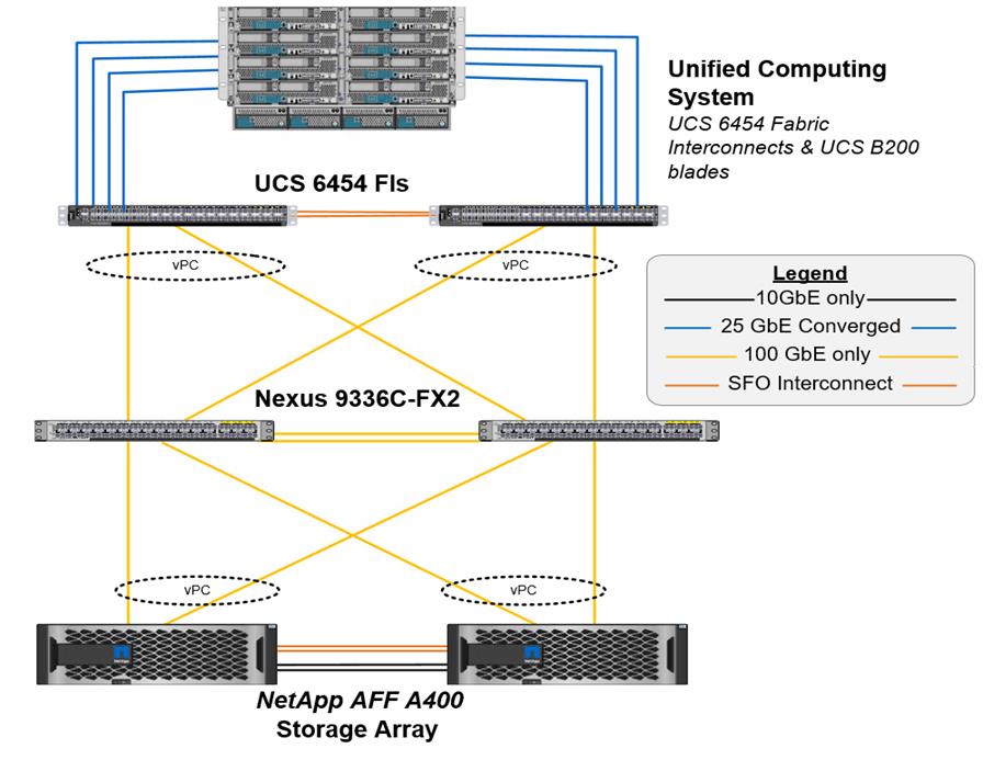
Figure 7 illustrates a base design. Each of the components can be scaled easily to support specific business requirements. For example, more (or different) servers or even blade chassis can be deployed to increase compute capacity, additional storage controllers or disk shelves can be deployed to improve I/O capability and throughput, and special hardware or software features can be added to introduce new features.
The following components are used to the validate and test the solution:
· 1x Cisco 5108 chassis with Cisco UCS 2408 IO Modules
· 5x B200 M5 Blades with VIC 1440 and an optional Port Expander card
· Two Cisco Nexus 9336C-FX2 switches
· Two Cisco UCS 6454 fabric interconnects
· One NetApp AFF A400 (high availability pair) running clustered Data ONTAP with NVMe Disk shelves and Solid-State Drives (SSD)
In this solution, VMware ESXi 6.7U3 virtual environments is tested and validated for deploying SQL Server 2019 databases on virtual machines running Windows Server 2019 guest operating system. SQL Server virtual machines are configured to connect the NetApp AFF400 storage luns directly using in-guest software iSCSI initiator. This approach bypasses the ESXI hypervisor VMFS storage layer for the luns that are used for storing SQL Server database files. This design approach gives better performance, simplified management, efficient backups of data and ability to associate storage QoS directly to objects hosting SQL data.
Table 1 lists the hardware and software components along with image versions used in the solution.
Table 1 Hardware and Software Components Specifications
| Layer |
Device |
Image |
Components |
| Compute |
Cisco UCS 4th generation 6454 Fabric Interconnects |
4.1(1c) |
Includes Cisco 5108 blade chassis with UCS 2408 IO Modules Cisco UCS B200 M5 blades with Cisco UCS VIC 1440 adapter. Each blade is configured with 2x Intel Xeon 6248 Gold processors and 384 GB (12x 32G) Memory. |
| Network Switches |
Includes Cisco Nexus 9336C-FX2 |
NX-OS: 9.3(4) |
|
| Storage Controllers |
NetApp AFF A400 storage controllers |
Data ONTAP 9.7 |
|
| Software |
Cisco UCS Manager |
4.1(1c) |
|
|
|
VMware vSphere ESXi |
6.7 U3 |
|
|
|
VMware vCenter |
6.7 U3 |
|
|
|
Microsoft Windows Server |
Windows Server 2019 |
For Virtual Machine Guest Operating System |
|
|
NetApp Virtual Storage Console (VSC) |
9.7 |
For Datastore storage provisioning to ESXi hosts |
|
|
NetApp SnapCenter |
4.3.1 |
For VM and SQL database backup, restore and protection |
|
|
NetApp ActiveIQ Manager |
9.7 |
Monitoring Storage infrastructure health and performance |
|
|
Microsoft SQL Server |
2019 (15.0.2000.5) |
|
This section describes the specific configurations and recommendations that are important for deploying FlexPod Datacenter for hosting Windows Server 2019 virtual machines running SQL Server 2019.
![]() This documentation does not provide all the steps for deploying FlexPod Datacenter with VMware vSphere 6.7 U3. Refer to the base infrastructure documentation here: FlexPod Datacenter with NetApp ONTAP 9.7, Cisco Intersight, and VMware vSphere 6.7 U3. The SQL Server 2019 deployment steps not explained in the infrastructure CVD are included in the following sections.
This documentation does not provide all the steps for deploying FlexPod Datacenter with VMware vSphere 6.7 U3. Refer to the base infrastructure documentation here: FlexPod Datacenter with NetApp ONTAP 9.7, Cisco Intersight, and VMware vSphere 6.7 U3. The SQL Server 2019 deployment steps not explained in the infrastructure CVD are included in the following sections.
Cisco UCS Manager Configuration
This section discusses specific Cisco UCS Manager policies that are different from the base FlexPod infrastructure configuration and important for obtaining optimal performance for SQL Server workloads.
As mentioned earlier, SQL Server virtual machines are configured to access the storage volumes directly using iSCSI protocol for storing database files. Hence it is important to use right network and adapter policies for low latency and better storage bandwidth as the underlying Cisco VIC network bandwidth is shared by many SQL Server virtual machines (for both management and storage access) as well as ESXi host management, vMotion and NFS traffics and so on.
VNIC Templates
The following vNIC templates are used on each ESXi host for various infrastructure and SQL virtual machine management traffics. The purpose of each vNIC template is listed below:
· vSwitch0-A: Is used for ESXi host management traffic via Fabric A
· vSwitch0-B: Is used for ESXi host management traffic via Fabric B
· SQL-vDS-A: Is used for the infrastructure management traffics like vMotion, NFS storage access, SQL virtual machine management and also for SQL iSCSI storage traffic via Fabric A.
· SQL-vDS-B: Is used for the infrastructure management traffics like vMotion, NFS storage access, SQL virtual machine management and also for SQL iSCSI storage traffic via Fabric B.
· SQL-iSCSI-Boot-A: Is used for booting ESXi host from NetApp Storage LUN using overlay network via Fabric A.
· SQL-iSCSI-Boot-B: Is used for booting ESXi host from NetApp Storage LUN using overlay network via Fabric B.
Table 2 lists additional configuration details of the vNICs templates used in this reference architecture.
| vNIC Template Name: |
vSwitch0-A |
vSwitch0-B |
SQL-vDS-A |
SQL-vDS-B |
SQL-ISCSI-Boot-A |
SQL-ISCSI-Boot-B |
| Purpose |
ESXi Host Management via Fabric-A |
ESXi Host Management via Fabric-B |
SQL Mgmt, SQL iSCSI, vMotion, NFS via Fabric-A |
SQL Mgmt, SQL iSCSI, vMotion, NFS via Fabric-B |
ESXi host SAN Boot via Fabric-A |
ESXi host SAN Boot via Fabric-B |
| Setting |
Value |
Value |
Value |
Value |
Value |
Value |
| Fabric ID |
A |
B |
A |
B |
A |
B |
| Fabric Failover |
Disabled |
Disabled |
Disabled |
Disabled |
Disabled |
Disabled |
| Redundancy Type
|
Primary Template. (Peer Redundancy: vSwitch0-B)
|
Secondary Template. (Peer Redundancy: vSwitch0-A) |
Primary Template (Peer Redundancy: SQL-vDS-B) |
Secondary Template (Peer Redundancy: SQL-vDS-A) |
No Redundancy |
No Redundancy |
| Target |
Adapter |
Adapter |
Adapter |
Adapter |
Adapter |
Adapter |
| Type |
Updating Template |
Updating Template |
Updating Template |
Updating Template |
Updating Template |
Updating Template |
| MTU |
9000 |
9000 |
9000 |
9000 |
9000 |
9000 |
| MAC Pool |
MAC-Pool-A |
MAC-Pool-B |
MAC-Pool-A |
MAC-Pool-B |
MAC-Pool-A |
MAC-Pool-B |
| QoS Policy |
Not-set |
Not-set |
Not-set |
Not-set |
Not-set |
Not-set |
| Network Control Policy |
Enable-CDP-LLDP |
Enable-CDP-LLDP |
Enable-CDP-LLDP |
Enable-CDP-LLDP |
Enable-CDP-LLDP |
Enable-CDP-LLDP |
| Connection Policy: VMQ |
Not-set |
Not-set |
SQL-VMQ |
SQL-VMQ |
Not-set |
Not-set |
| VLANs |
IB-Mgmt (113) |
IB-Mgmt (113) |
SQL-iSCSI-A (3015), SQL-iSCSI-B (3025), SQL-Mgmt (905), SQL-NFS (3055), vMotion (3000) |
SQL-iSCSI-A (3015), SQL-iSCSI-B (3025), SQL-Mgmt (905), SQL-NFS (3055), vMotion (3000) |
SQL-iSCSI-A (3015) |
SQL-iSCSI-B (3025) |
| Native VLAN |
No |
No |
No |
No |
3015 |
3025 |
![]() Ensure the ports on the upstream switches are appropriately configured with the MTU and VLANs for end-to-end consistent configuration.
Ensure the ports on the upstream switches are appropriately configured with the MTU and VLANs for end-to-end consistent configuration.
Table 3 lists additional information about the VLANs used for various purposes in the reference architecture.
| VLAN Name |
VLAN Purpose |
ID used in this architecture validation |
| In Band Mgmt |
VLAN for in-band management of ESXi hosts |
113 |
| Native-VLAN |
VLAN to which untagged frames are assigned |
2 |
| SQL-MGMT |
VLAN for in-band management of SQL Server Virtual Machines |
905 |
| SQL-Client |
VLAN for SQL Server – Client communication Traffic or for other traffic coming into services running in VM |
1000 |
| SQL-iSCSI-A |
VLAN for iSCSI A traffic for SQL virtual machines on ESXi as well as ESXi Infrastructure |
3015 |
| SQL-iSCSI-B |
VLAN for iSCSI B traffic for SQL virtual machines on ESXi as well as ESXi Infrastructure |
3025 |
| vMotion |
VLAN for VMware vMotion |
3000 |
| SQL-NFS |
VLAN for accessing NetApp storage LUNS using NFS protocol by ESXI hosts (used for storing VMs OS disks (.vmdk)). |
3055 |
| Out of Band Mgmt |
VLAN for out-of-band management of B200 M5 Blades |
17 |
By leveraging above vNIC templates, a LAN connectivity policy is created and within this policy six vNICs have been derived in the specific order as shown below figure. Every ESXI server will detect the network interfaces in the same order, and they will always be connected to the same VLANs via the same network fabrics.
Figure 8 vNICs Derived using LAN Connectivity Policy
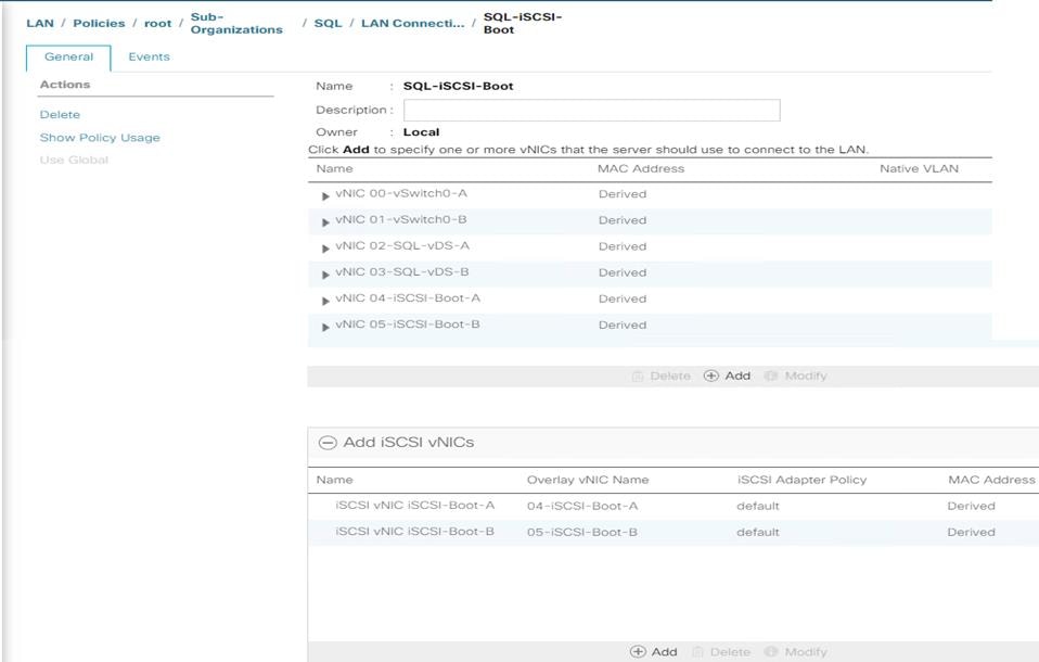
The bottom two iSCSI vNICs are overlay network adapters which are detected during the ESXi boot itself, establish connections to the NetApp storage array and boots the UCS B200 M5 blade from storage SAN LUN.
VMQ Policy
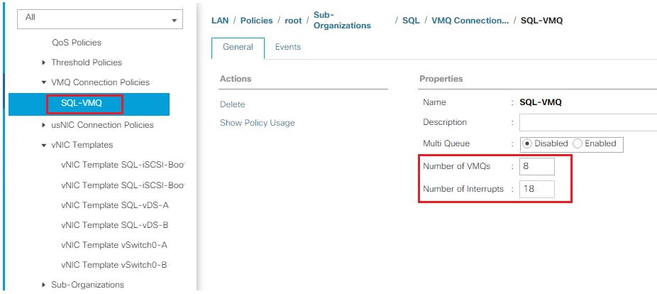
To help reduce the burden for the hypervisor and eliminate the queue sharing, the Cisco UCS VIC can create dedicated queue pairs for guest machines running under VMware ESXi. This approach provides significant benefits. First, the transmit and receive queue pairs are no longer shared with other guest machines. Second, the hypervisor is no longer responsible for sorting and switching packets because packet steering is moved to the adapter. The adapter performs packet steering based on Layer 2 information such as MAC address and VLAN. As a result, the hypervisor is responsible only for moving the traffic between the adapter and the virtual machine. This approach improves I/O performance and frees the hypervisor for other tasks. The Cisco UCS VIC supports up to 128 virtual machine queues (VMQs) per vNIC and a total of 256 VMQs per adapter.
Create a VMQ policy with appropriate settings as shown below. The Number of VMQs is typically no of virtual machines in the host and number of interrupts will be 2x VMQ +2.
Figure 9 VMQ Policy
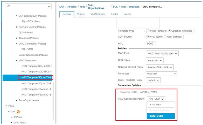
The VMQ policy needs to be applied on the SQL-vDS-A and SQL-vDS-B vNIC templates. Figure 10 shows applying VMQ policy on the SQL-vDS-A vNIC template.
Figure 10 Applying VMQ Policy to SQL-vDS-A vNIC Template
Adapter Policy
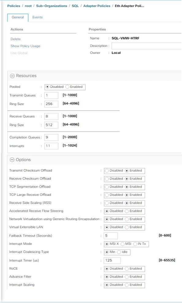
The adapter policy allows the administrator to declare the capabilities of the vNIC, such as the number of rings, ring sizes, and offload enablement and disablement. The Transmit Queues, Receive Queues defined in the default VMware Adapter policy may not be sufficient as more SQL Server databases are consolidated on the FlexPod System.
![]() It is recommended to increase the Transmit and Receive queues in smaller increments added with sufficient testing based on workload demand instead of setting them directly to the highest possible values. Changes to these settings need to be thoroughly tested before using in the production deployment.
It is recommended to increase the Transmit and Receive queues in smaller increments added with sufficient testing based on workload demand instead of setting them directly to the highest possible values. Changes to these settings need to be thoroughly tested before using in the production deployment.
Figure 11 shows a sample adapter policy used for FlexPod system built using VMware ESXi clusters for running SQL Server database workloads. As more SQL virtual machines are added to the cluster, depending on network bandwidth requirements, the number of queues and buffer sizes can be increased in smaller steps.
Receive Side Scaling (RSS) improves the performance by scheduling the interrupts on multiple cores on the host. Offloading networking functions such as checksum, segmentation, and so on, from host to Adapter will reduce the host CPU requirements to process these functions.
Figure 11 Adapter Policy for Higher Network Throughput
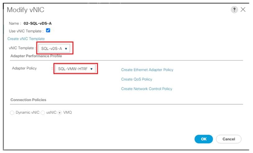
Using the LAN connectivity policy, the new adapter policy can be applied to vNICs used for serving SQL Server storage traffic. In this reference architecture, this new adapter policy is applied to vNICs that are derived from SQL-vDS-A and SQL-vDS-B templates. Figure 12 shows applying the new adapter policy SQL-VMW-HTRF to the 02-SQL-vDS-A vNIC.
Figure 12 Applying Adapter Policy Using LAN Connectivity Policy
For more information on the VIC tuning options and performance validation, refer to the following links:
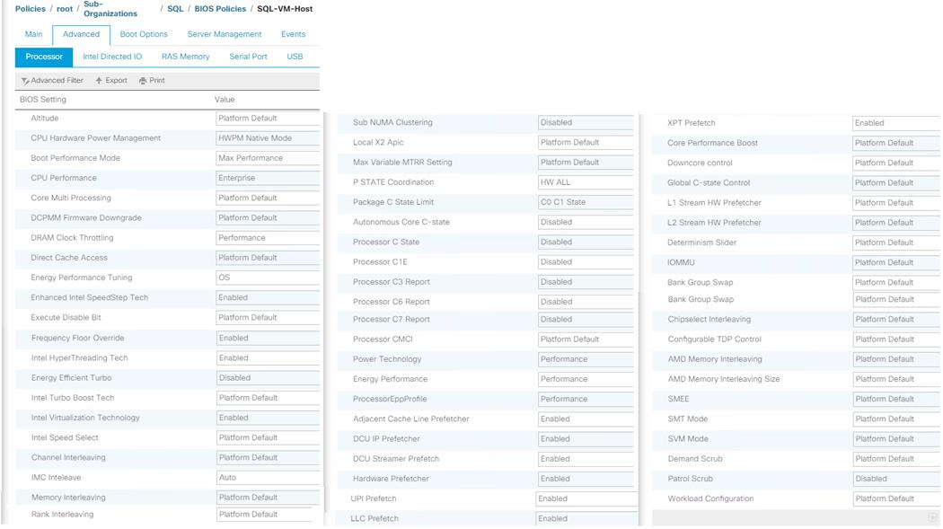
BIOS Policy
It is recommended to use appropriate BIOS settings on the servers based on the workload they run. The default bios settings work towards power savings by reducing the operating speeds of processors and move the cores to the deeper sleeping states. These states need to be disabled for sustained high performance of database queries. The following BIOS settings are used in our performance tests for obtaining optimal system performance for SQL Server OLTP workloads on Cisco UCS B200 M5 server.
Figure 13 Bios policy for Cisco UCS B200 M5 Blade Server
The remaining policies and configuration steps for deploying FlexPod System for hosting SQL Server virtual machines are same as the base infrastructure CVD as described here: https://www.cisco.com/c/en/us/td/docs/unified_computing/ucs/UCS_CVDs/fp_dc_ontap_97_ucs_4_vmw_vs_67_U3.html#_Toc41630093
For iSCSI specific UCS and ESXi host configuration steps, please refer “Create iSCSI Boot Service Profile Template” section in the infrastructure CVD as described here: https://www.cisco.com/c/en/us/td/docs/unified_computing/ucs/UCS_CVDs/fp_dc_ontap_97_ucs_4_vmw_vs_67_U3.html#_Toc41630249
NetApp Management Tools Setup and Configuration
This section provides more information about how to configure NetApp management tool like Virtual Storage console (VSC) and SnapCenter which are used and validated in this solution.
Virtual Storage Console (VSC) 9.7
Refer to the NetApp Virtual Storage Console (VSC) 9.7 Deployment section of the FlexPod Infrastructure CVD, for the VSC deployment steps.
NetApp VSC 9.7 was used in this solution validation to provision storage for VMware ESXi datastores for virtual machines.
SnapCenter 4.3
NetApp SnapCenter 4.3 was used in this solution validation for following use cases:
· Backup and restore of VMware virtual machines.
· Backup, restore, protection and cloning of SQL Databases.
· Storage provisioning for SQL databases and logs.
Installation of SnapCenter 4.3
Refer to the NetApp SnapCenter 4.3 Installation and Configuration section of the FlexPod Infrastructure CVD, for the SnapCenter 4.3 Installation steps. Installation and configuration of the SnapCenter Plug-in for VMWare vCenter is required for the VM Backup/Restore and is also explained in the FlexPod Infrastructure CVD.
Installation of SnapCenter Plug-in for SQL
SnapCenter Plug-in for Microsoft SQL Server is required to protect SQL Server databases using SnapCenter. SnapCenter Plug-in for Microsoft SQL Server and SnapCenter Plug-in for Microsoft Windows, both are required on each Windows VM running SQL server.
Refer to the Installation guide for SnapCenter Plug-in for Microsoft SQL Server, for prerequisites and installation steps. When a Host (Windows VM) running SQL Server is added to SnapCenter, SnapCenter Plug-in for Microsoft SQL Server and SnapCenter Plug-in for Microsoft Windows are installed on the VM. Steps to add Host to SnapCenter are in Add Hosts (Windows VMs) to SnapCenter.
Table 4 Port Requirements
| Port |
Requirement |
| 443 (HTTPS) |
Used for communication between the SnapCenter Server and SVM management LIF of ONTAP. |
| 8146 (HTTPS) |
Used for communication between the SnapCenter client (the SnapCenter user) and the SnapCenter Server. Also used for communication from the plug-in hosts to the SnapCenter Server. |
| 135, 445 (TCP) on Windows plug-in hosts |
The ports are used for communication between the SnapCenter Server and the host on which the plug-in is being installed. To push plug-in package binaries to Windows plug-in hosts, the ports must be open only on the plug-in host, and they can be closed after installation. |
| 8145 (HTTPS), bidirectional |
The port is used for communication between SMCore and hosts where the SnapCenter plug-ins package for Windows is installed. |
| 1433 (TCP) |
Port for SQL Server management access |
License Requirements for SnapCenter Plug-in for SQL Server
The following licenses are required to be installed on the ONTAP storage system to backup and restore SQL Server databases:
Table 5 SnapCenter Plug-in for Microsoft SQL Server License Requirements
| Product |
License Requirements |
| ONTAP Primary |
For SnapCenter Plug-in for of SQL Server, following licenses should be installed: One of these: SnapMirror or SnapVault (for secondary data protection regardless of the type of relationship) SnapManagerSuite: used for SnapCenter functionality SnapRestore: used for restore operations FlexClone: used for mount and attach operations |
| ONTAP Secondary Destinations |
To perform protection of SQL databases, on secondary storage: FlexClone: used for mount and attach operations |
|
|
|
Active IQ Unified Manager 9.7
Refer to the Active IQ Unified Manager 9.7 section of the Infrastructure CVD for the Active IQ Unified Manager Installation and Configuration steps.
NetApp Storage Configuration for Windows VMs on ESXi and SQL Databases
On NetApp storage cluster, Storage Virtual Machines (SVMs) is created for ESXi Datastores for Windows Server 2019 virtual machines and SQL Server databases and logs.
Create Storage Virtual Machine (SVM) for SQL Workload
SVM for SQL Server Databases serves as logical storage system for Windows VMs and SQL Databases, called SQL SVM.
To create an SQL SVM, follow these steps:
1. Run the vserver create command.
vserver create –vserver SQL-SVM –rootvolume rootvol –aggregate aggr1_node01 –rootvolume-security-style unix
2. Select the SVM data protocols to configure, keeping iSCSI and nfs only.
vserver remove-protocols –vserver SQL-SVM -protocols fcp,cifs,ndmp
3. Add the two data aggregates to the SQL-SVM aggregate list for the NetApp VSC.
vserver modify –vserver SQL-SVM –aggr-list aggr1_node01,aggr1_node02
4. Enable and run the NFS protocol in the Infra-SVM.
nfs create -vserver Infra-SVM -udp disabled
5. Turn on the SVM vStorage parameter for the NetApp NFS vStorage APIs – Array integration VAAI plug-in.
vserver nfs modify –vserver SQL-SVM –vstorage enabled
vserver nfs show
Create Load-Sharing Mirrors of SVM Root Volume
To create a load-sharing mirror of an SVM root volume, follow these steps:
1. Create a volume to be the load-sharing mirror of the infrastructure SVM root volume on each node.
volume create –vserver SQL-SVM –volume rootvol_m01 –aggregate aggr1_node01 –size 1GB –type DP
volume create –vserver SQL-SVM –volume rootvol_m02 –aggregate aggr1_node02 –size 1GB –type DP
2. Create a job schedule to update the root volume mirror relationships every 15 minutes.
job schedule interval create -name 15min -minutes 15
3. Create the mirroring relationships.
snapmirror create –source-path SQL-SVM:rootvol –destination-path SQL-SVM:rootvol_m01 –type LS -schedule 15min
snapmirror create –source-path SQL-SVM:rootvol –destination-path SQL-SVM:rootvol_m02 –type LS -schedule 15min
4. Initialize the mirroring relationship.
snapmirror initialize-ls-set –source-path SQL-SVM:rootvol
snapmirror show
5. Create Block Protocol (iSCSI) Service.
Run the following command to create the iSCSI service on SVM. This command also starts the iSCSI service and sets the IQN for the SVM.
iscsi create -vserver SQL-SVM
iscsi show
Configure HTTPS Access
To configure secure access to the storage controller, follow these steps:
1. Increase the privilege level to access the certificate commands.
set -privilege diag
Do you want to continue? {y|n}: y
2. Generally, a self-signed certificate is already in place. Verify the certificate and obtain parameters (for example, <serial-number>) by running the following command:
security certificate show
3. For each SVM shown, the certificate common name should match the DNS FQDN of the SVM. Delete the two default certificates and replace them with either self-signed certificates or certificates from a certificate authority (CA). To delete the default certificates, run the following commands:
security certificate delete -vserver SQL-SVM -common-name SQL-SVM -ca SQL-SVM -type server -serial <serial-number>
![]() Deleting expired certificates before creating new certificates is a best practice. Run the security certificate delete command to delete the expired certificates. In the following command, use TAB completion to select and delete each default certificate.
Deleting expired certificates before creating new certificates is a best practice. Run the security certificate delete command to delete the expired certificates. In the following command, use TAB completion to select and delete each default certificate.
4. To generate and install self-signed certificates, run the following commands as one-time commands. Generate a server certificate for the SQL-SVM and the cluster SVM. Use TAB completion to aid in the completion of these commands.
security certificate create -common-name <cert-common-name> -type server -size 2048 -country <cert-country> -state <cert-state> -locality <cert-locality> -organization <cert-org> -unit <cert-unit> -email-addr <cert-email> -expire-days <cert-days> -protocol SSL -hash-function SHA256 -vserver SQL-SVM
5. To obtain the values for the parameters required in step 5 (<cert-ca> and <cert-serial>), run the security certificate show command.
6. Enable each certificate that was just created by using the –server-enabled true and –client-enabled false parameters. Use TAB completion to aid in the completion of these commands.
security ssl modify -vserver <clustername> -server-enabled true -client-enabled false -ca <cert-ca> -serial <cert-serial> -common-name <cert-common-name>
7. Revert to the normal admin privilege level and set up the system to allow SVM logs to be available by web.
set –privilege admin
vserver services web modify –name spi|ontapi|compat –vserver * -enabled true
Storage for SQL Server Databases
Application administrator need access to SQL SVM to perform following tasks:
· Provisions storage for SQL Databases
· Backup, Restore, Clone and Protect SQL Databases
Create FlexVol Volumes for SQL Database and Logs
Create FlexVol volumes, by running the following commands. The information required to create a NetApp FlexVol volume is as follows:
· The volume name
· The volume size
· The aggregate on which the volume exists
Distribute SQL data and log volumes on two aggregates equally, to balance the performance and capacity utilization:
volume create -vserver SQL-SVM -volume sql_data_a -aggregate aggr1_node01 -size 2TB -state online -policy default -junction-path / sql_data_a -space-guarantee none -percent-snapshot-space 0
volume create -vserver SQL-SVM -volume sql_data_b -aggregate aggr1_node02 -size 2TB -state online -policy default -junction-path / sql_data_b -space-guarantee none -percent-snapshot-space 0
volume create -vserver SQL-SVM -volume sql_log_a -aggregate aggr1_node01 -size 800GB -state online -policy default -junction-path /sql_log_a -space-guarantee none -percent-snapshot-space 0
volume create -vserver SQL-SVM -volume sql_log_b -aggregate aggr1_node02 -size 800GB -state online -policy default -junction-path /sql_log_b -space-guarantee none -percent-snapshot-space 0
snapmirror update-ls-set -source-path SQL-SVM:rootvol
Create SQL Database and Log LUNs
To create SQL database and log LUNs, follow this step:
1. Create four LUNs for SQL databases and four LUNs for logs to map to Windows VMs, by running the following commands:
lun create -vserver SQL-SVM -volume sql_data_a -lun sql-db-1 -size 400GB -ostype windows -space-reserve disable
lun create -vserver SQL-SVM -volume sql_data_a -lun sql-db-2 -size 400GB -ostype windows -space-reserve disable
lun create -vserver SQL-SVM -volume sql_data_a -lun sql-db-3 -size 400GB -ostype windows -space-reserve disable
lun create -vserver SQL-SVM -volume sql_data_a -lun sql-db-4 -size 400GB -ostype windows -space-reserve disable
lun create -vserver SQL-SVM -volume sql_log_a -lun sql-log-1 -size 150GB -ostype windows -space-reserve disable
lun create -vserver SQL-SVM -volume sql_log_a -lun sql-log-2 -size 150GB -ostype windows -space-reserve disable
lun create -vserver SQL-SVM -volume sql_log_a -lun sql-log-3 -size 150GB -ostype windows -space-reserve disable
lun create -vserver SQL-SVM -volume sql_log_a -lun sql-log-4 -size 150GB -ostype windows -space-reserve disable
Create iSCSI LIFs
To create iSCSI LIFs, follow this step:
1. Create four iSCSI LIFs (two on each node), by running the following commands:
network interface create -vserver SQL-SVM -lif iscsi-lif01a -role data -data-protocol iscsi -home-node <a400-node01> -home-port a0a-<SQL-VM-iSCSI-A-id> -address <sql-svm-iscsi-lif01a_ip> -netmask <iscsi_lif_mask> –status-admin up –failover-policy disabled –firewall-policy data –auto-revert false
network interface create -vserver SQL-SVM -lif iscsi-lif01b -role data -data-protocol iscsi -home-node <a400-node01> -home-port a0a-<SQL-VM-iSCSI-B-id> -address <sql-svm-iscsi-lif01b_ip> -netmask < iscsi_lif_mask > –status-admin up –failover-policy disabled –firewall-policy data –auto-revert false
network interface create -vserver SQL-SVM -lif iscsi-lif02a -role data -data-protocol iscsi -home-node <a400-node02> -home-port a0a-<SQL-VM-iSCSI-A-id> -address <sql-svm-iscsi-lif02a_ip> -netmask <iscsi_lif_mask> –status-admin up –failover-policy disabled –firewall-policy data –auto-revert false
network interface create -vserver SQL-SVM -lif iscsi-lif02b -role data -data-protocol iscsi -home-node <a400-node02> -home-port a0a-<SQL-VM-iSCSI-B-id> -address <sql-svm-iscsi-lif02b_ip> -netmask < iscsi_lif_mask > –status-admin up –failover-policy disabled –firewall-policy data –auto-revert false
network interface show
Create NFS LIFs
To create NFS LIFs, follow this step:
1. Create two NFS LIFs (one on each node), by running following commands:
network interface create -vserver SQL-SVM -lif nfs-lif01 -role data -data-protocol nfs -home-node <a400-node01> -home-port a0a-<SQL-VM-NFS-id> -address <sql-svm-nfs-lif02_ip> -netmask <iscsi_lif_mask> –status-admin up –failover-policy disabled –firewall-policy data –auto-revert false
network interface create -vserver SQL-SVM -lif nfs-lif02 -role data -data-protocol nfs -home-node <a400-node02> -home-port a0a-<SQL-VM-NFS-A-id> -address <sql-svm-nfs-lif02_ip> -netmask <iscsi_lif_mask> –status-admin up –failover-policy disabled –firewall-policy data –auto-revert false
network interface show
Add SVM Administrator
To add the infrastructure SVM administrator and SVM administration LIF in the out-of-band management network, follow these steps:
1. Run the following commands:
network interface create -vserver SQL-SVM -lif SQL-SVM-mgmt -role data -data-protocol none -home-node <st-node01> -home-port e0c -address <SQL-SVM-Mgmt_ip> -netmask <SQL-SVM-Mgmt_mask> –status-admin up –failover-policy system-defined –firewall-policy mgmt –auto-revert true
![]() The SVM management IP in this step should be in the same subnet as the storage cluster management IP.
The SVM management IP in this step should be in the same subnet as the storage cluster management IP.
2. Create a default route to allow the SVM management interface to reach the outside world.
network route create –vserver SQL-SVM -destination 0.0.0.0/0 –gateway <svm-mgmt-gateway>
network route show
3. Set a password for the SVM vsadmin user and unlock the user.
security login password –username vsadmin –vserver SQL-SVM
Enter a new password: <password>
Enter it again: <password>
security login unlock –username vsadmin –vserver SQL-SVM
![]() A cluster serves data through at least one and possibly several SVMs. We have just created a single SVM. If you would like to configure your environment with multiple SVMs, this is a good time to create additional SVMs.
A cluster serves data through at least one and possibly several SVMs. We have just created a single SVM. If you would like to configure your environment with multiple SVMs, this is a good time to create additional SVMs.
Create Storage Volumes for Windows Virtual Machines (ESXi Datastore)
SVM for Windows Server 2019 VMs serves as a logical storage system for ESXi datastores, called Infrastructure SVM. Infrastructure SVM is managed by the Infrastructure admin, authorized to perform the following tasks:
· Provisions storage for ESXi datastores
· Backup and Restore VMs
Create Storage Volumes for Windows VMs Datastore and VM Swap Files
To create storage volumes for Windows VMs datastores and VM swap files, follow this step:
1. Create FlexVols for SQL Virtual Machine Datastores and Swap datastore, by running the following commands:
volume create -vserver SQL-SVM -volume sql_vms_ds1 -aggregate aggr1_node01 -size 800GB -state online -policy default -junction-path /sql_vms_ds1 -space-guarantee none -percent-snapshot-space 0
volume create -vserver SQL-SVM -volume sql_vms_ds2 -aggregate aggr1_node02 -size 800GB -state online -policy default -junction-path /sql_vms_ds2 -space-guarantee none -percent-snapshot-space 0
volume create -vserver SQL-SVM -volume sql_vms_swap -aggregate aggr1_node01 -size 300GB -state online -policy default -junction-path /sql_vms_swap -space-guarantee none -percent-snapshot-space 0
Schedule Deduplication
On NetApp AFF systems, deduplication is enabled by default. To schedule deduplication, follow this step:
1. After the volumes are created, assign a once-a-day deduplication schedule to volumes:
efficiency modify –vserver SQL-SVM –volume sql_data_a –schedule sun-sat@0
efficiency modify –vserver SQL-SVM –volume sql_data_b –schedule sun-sat@0
efficiency modify –vserver SQL-SVM –volume sql_vms_ds1 –schedule sun-sat@0
efficiency modify –vserver SQL-SVM –volume sql_vms_ds2 –schedule sun-sat@0
Gather Necessary Information
After the Cisco UCS service profiles have been created, each infrastructure server in the environment will have a unique configuration. To proceed with the FlexPod deployment, specific information must be gathered from each Cisco UCS server and from the NetApp controllers. Insert the required information into following tables.
![]() To obtain the iSCSI IQN, run iscsi show command on the storage cluster management interface.
To obtain the iSCSI IQN, run iscsi show command on the storage cluster management interface.
Table 6 iSCSI IQN, iSCSI LIFs, and NFS LIFs
| IQN or LIF IP |
Info |
| SQL-SVM IQN |
|
| sql-svm-iscsi-lif01a_ip |
|
| sql-svm-iscsi-lif01b_ip |
|
| sql-svm-iscsi-lif02a_ip |
|
| sql-svm-iscsi-lif02b_ip |
|
| sql-svm-nfs-lif01_ip |
|
| sql-svm-nfs-lif02_ip |
|
VMware ESXi Host Configuration
This section describes the VMWare ESXi host specific configuration to be implemented on each ESXi host. These changes are required for achieving optimal system performance for SQL Server workloads.
Power Settings
An ESXi host can take advantage of several power management features that the hardware provides to adjust the trade-off between performance and power use. You can control how ESXi uses these features by selecting a power management policy.
ESXi has been heavily tuned for driving high I/O throughput efficiently by utilizing fewer CPU cycles and conserving power. Hence the Power setting on the ESXi host is set to “Balanced.” However, for critical database deployments, it is recommended to set the power setting to “High Performance.” Selecting “High Performance” causes the physical cores to run at higher frequencies and thereby it will have positive impact on the database performance. The ESXi host power setting is shown in the following figure:
Figure 14 ESXi Host Power Policy
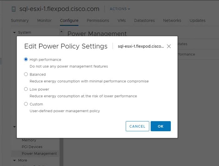
ESXi Host Networking Configuration
This section provides more information about ESXi host network configuration for this FlexPod system hosting SQL Server virtual machines.
Note that the Cisco UCS LAN connectivity policy ensures that vNICs are presented to the ESXi in the same order that they are derived in the LAN connectivity policy. Table 7 lists the order in which the vNICs will be mapped to the ESXi host physical adapters.
Table 7 UCSM vNICs to ESXi Physical Adapters Mapping
| vNIC Name |
ESXi Physical Adapter & Speed |
| 00-vSwitch0-A |
vmnic0, 20Gbps |
| 01-vSwitch0-B |
Vmnic1, 20Gbps |
| 02-SQL-vDS-A |
Vmnic2, 20Gbps |
| 03-SQL-vDS-B |
Vmnic3, 20Gbps |
| 04-iSCSI-Boot-A |
Vmnic4, 20Gbps |
| 05-iSCSI-Boot-B |
Vmnic5, 20Gbps |
In this reference architecture, the infrastructure ESXi management VMkernel ports, the In-Band management interfaces including the vCenter management interface are left on vSwitch0 to facilitate bringing the virtual environment back up in the event it needs to be completely shut down. other infrastructure network traffics, like vMotion, NFS storage access along with SQL virtual machines management and in-guest storage networks are migrated to the VMware vSphere Distributed Switch (vDS). The vMotion VMkernel ports are moved to the vDS to allow QoS marking of vMotion to be done at the VLAN level in the vDS if vMotion needs to have QoS policies applied in the future. The following sections provides more details network configuration.
ESXi Host Management Network
A default standard virtual switch, vSwicth0, is created for managing the ESXi host management traffic. This switch is created using two physical network adapters vmnic0 and vmnic1 in active-active fashion. A default VMkernel adapter is assigned to this switch using the default “Management Network” port group. Table 8 lists the details about the vSwicth0 and their port group details.
Table 8 vSphere Standard Switch and Port Group configuration for ESXi Host Storage Traffic
| Configuration |
Details |
| Switch Name |
vSwicth0 |
| Number of physical Adapters (uplinks) |
vmnic0 and vmnic1 |
| MTU Setting |
1500 |
| Port Groups created on this Standard Switch |
|
| Management Network
|
Purpose: For managing and accessing ESXi hosts Active Uplinks: vmnic0 and vmnic1 VLAN: 113 A VMkernel port (vmk0) is configured with appropriate IP addresses on each ESXI host. MTU on the vmk0 : 1500 |
| IB-MGMT (optional) |
Purpose: For managing and accessing ESXi hosts for any other user groups/Applications Active Uplinks: vmnic0 and vmnic1 VLAN: 113 |
Figure 15 shows the vSwitch0 standard switch with vmnic0 and vmnic1 adapters configured in active-active fashion.
Figure 15 ESXi Host Management Network
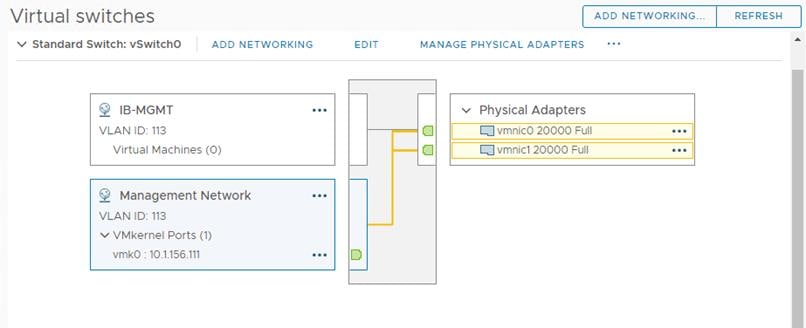
ESXi iSCSI Storage Network
A default standard virtual switch, iScsiBootvSwitch, is created for accessing NetApp storage using iSCSI protocol. This switch is created using two physical network adapters vmnic4 and vmnic5. The storage traffic to NetApp storage array is divided in to two different fabrics via Fabric Interconnect A and B. Hence a separate port group is created for each fabric and allowing traffic on one vmnic adapter only. For instance, iScsiBootPG port group is configured with only vmnic4 adapter as active (vmnic5 is unused). Similarly, iScsiBootPG-B port group is configured with only vmnic5 adapter as active (vmnic4 is unused). This enables the storage traffic to be segregated on each fabric. Table 9 lists the details about the iSCSIBootvSwitch and their port group.
Table 9 vSphere Standard Switch and Port Group Configuration for ESXi Host Storage Traffic
| Configuration |
Details |
| Switch Name |
iScsiBootvSwitch |
| Number of physical Adapters (uplinks) |
Vmnic4 and vmnic5 |
| MTU Setting |
9000 |
| Port Groups created on this Standard Switch |
|
| iSCSIBootPG
|
Purpose: For ESXi host boot from NetApp storage with iSCSI initiator via Fabric A. Active Uplink: vmnic4 Unused Uplink: vmnic5 VLAN: NA ( VLAN 3015 will be tagged at the UCSM vNICs as native VLAN, Refer “List of vNICs” table) A VMkernel port (vmk1) is configured with appropriate IP addresses on each ESXI host. MTU on the vmk1 : 9000 |
| iSCSIBootPG-B |
Purpose: For ESXi host boot from NetApp storage with iSCSI initiator via Fabric B. Active Uplink: vmnic5 Unused Uplink: vmnic4 VLAN: NA ( VLAN 3025 will be tagged at the UCSM vNICs as native VLAN, Refer “List of vNICs” table) A VMkernel port (vmk2) is configured with appropriate IP addresses on each ESXI host. MTU on the vmk2 : 9000 |
Figure 16 shows iScsiBootPG port group properties.
Figure 16 ESXi Host Management Network
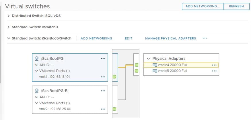
FlexPod VMware vSphere Distributed Switch for SQL and Other Infrastructure Management Traffic
In this reference architecture, the SQL virtual machine management traffic, SQL in-guest storage traffic, ESXi vMotion traffic and ESXi NFS based storage traffics are moved to the vDS switch. Table 10 lists the details about the vDS switch and the different port groups created for each traffic type.
Table 10 vSphere Distributed Switch and Port Group Configuration
| Configuration |
Details |
| vDS Name |
SQL-vDS |
| Number of uplinks |
2 uplinks; vmnic2 (uplink1) and vmnic3 (uplink2) |
| MTU Setting |
9000 |
| Distributed Port Groups created on this vDS |
|
| SQL-MGMT
|
Purpose: For managing and accessing SQL Server virtual machines. The uplinks are configured in Active-Active fashion so that both the uplinks will be used by SQL management traffic. VLAN: 905 |
| SQL-Client |
Purpose: For SQL Database traffic between SQL Server Database VMs and Clients. The uplinks are configured in Active-Active fashion so that both the uplinks will be used by SQL management traffic. VLAN: 1000 |
| SQL-iSCSI-A |
Purpose: For accessing NetApp storage from SQL virtual machines using in-guest software iSCSI initiator via Fabric A. This traffic is pinned to only uplink. Hence only uplink1 is configured as Active while the other uplink is unused. VLAN: 3015 |
| SQL-iSCSI-B |
Purpose: For accessing NetApp storage from SQL virtual machines using in-guest software iSCSI initiator via Fabric B. This traffic is pinned to only uplink. Hence only uplink2 is configured as Active while the other uplink is unused. VLAN: 3025 |
| SQL-NFS |
Purpose: For ESXi host storage access over NFS protocol. Datastores mounted on ESXi hosts for storing SQL virtual machines OS drives (.vmdk files) The uplinks are configured in Active-Active fashion so that both the uplinks will be used by ESXi host NFS storage traffic. VLAN: 3055 A VMkernel port (vmk3) is configured with appropriate IP addresses on each ESXI host. MTU on the vmk3 : 9000 |
| SQL-vMotion |
Purpose: For virtual machine migration from one host to other. This traffic is pinned to Fabric B. Hence only uplink2 is configured as Active while the other uplink is unused. VLAN:3000 A VMkernel port (vmk4) is configured with appropriate IP addresses on each ESXI host. MTU on the vmk4 : 9000 |
Figure 17 shows all the port groups configured on the SQL-vDS distributed switch on an ESXi host highlighting one of the SQL-iSCSI-B port group.
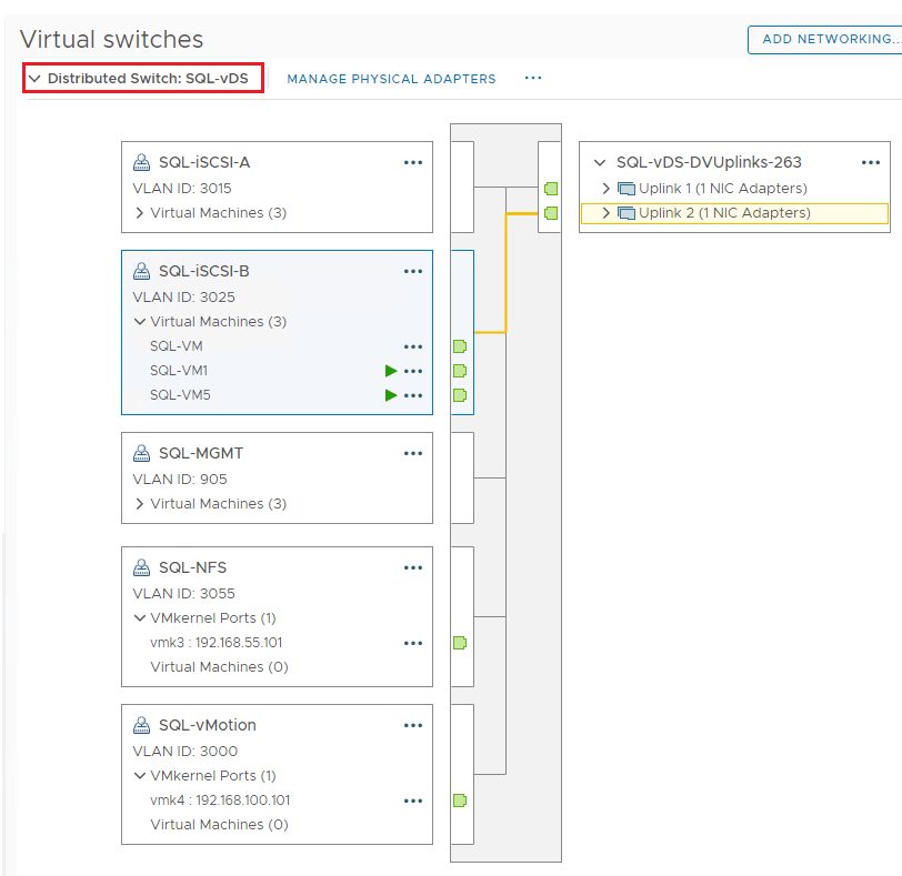
Verifying ESXi Host NetQueue Feature
As described in the Cisco UCS Manager VMQ Policy section, the VMQ policy (with 8 queues) is applied to the vmnic2 and vmnic3 physical adapters of ESXi host. Figure 18 shows how to verify that the VMQ policy is applied properly on the ESXi (as NetQueue feature) and shows the number of transmit and receive queues available on each physical adapter that are part of SQL-vDS distributed switch.
Figure 18 ESXi NetQueue Feature Verification
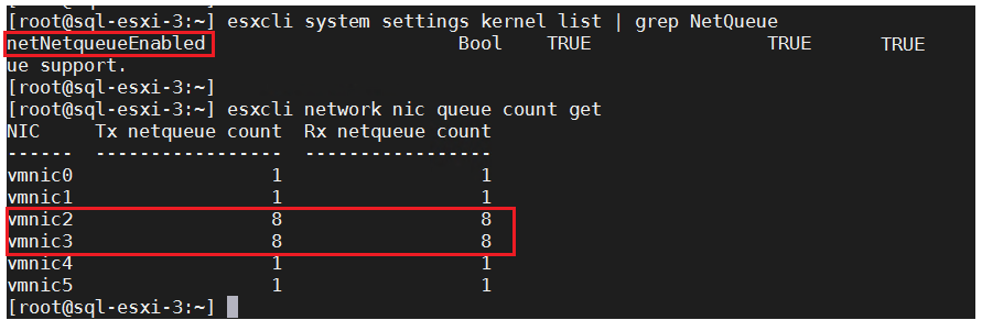
For more information about the ESXi NetQueue features, refer to: https://docs.vmware.com/en/VMware-vSphere/6.5/com.vmware.vsphere.networking.doc/GUID-6B708D13-145F-4DDA-BFB1-39BCC7CD0897.html
ESXi Host Logical Network Diagram
Figure 19 shows the logical network diagram of ESXi host depicting all the port groups and VMkernel adapters of the ESXi host described in the previous sections.
Figure 19 ESXi Logical Network Diagram
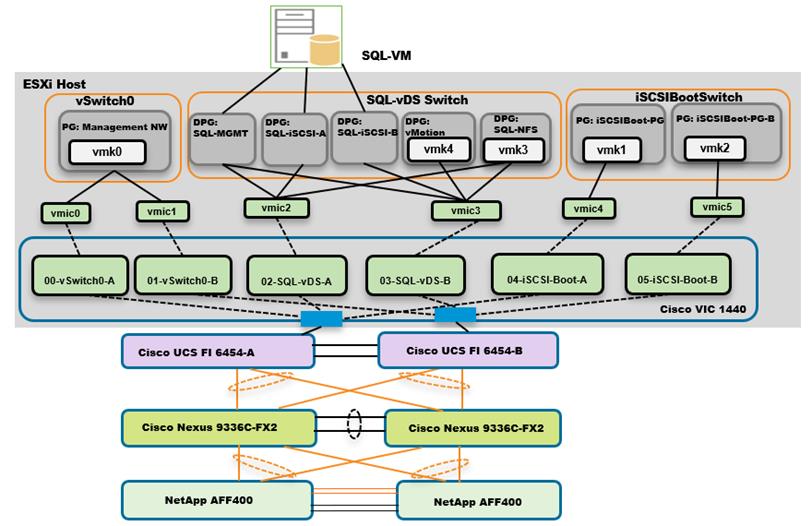
As shown in Figure 19, SQL Server virtual machines are configured with following networks:
· SQL-MGMT: Virtual Network Adapter connected to the SQL-MGMT port group and is used for SQL Server virtual machines management traffic and also used for SQL and Client communication.
· SQL-ISCSI-A: Virtual Network Adapter connected to the SQL-iSCSI-A port group and is used to connect to NetApp storage using in-Guest iSCSI initiator via Fabric-A.
· SQL-ISCSI-B: Virtual Network Adapter connected to the SQL-iSCSI-B port group and is used to connect to NetApp storage using in-Guest iSCSI initiator via Fabric-B.
![]() SQL-MGMT network is used for both SQL guest management as well as the SQL Server-Client communication. Customers can create additional port groups with the appropriate VLAN to segregate SQL guest management traffic and SQL Server-Client traffic.
SQL-MGMT network is used for both SQL guest management as well as the SQL Server-Client communication. Customers can create additional port groups with the appropriate VLAN to segregate SQL guest management traffic and SQL Server-Client traffic.
Provision ESXi Datastore for Windows Virtual Machines from vCenter VSC Plug-in (Virtual Storage Console)
Ensure the VSC 9.7 and VSC plug-in for vCenter are installed as described in the NetApp Virtual Storage Console (VSC) 9.7 Deployment section of the infrastructure CVD.
To provision the ESXi datastore for Windows Virtual Machines from the vCenter VSC plug-in, follow these steps:
1. Login to the vCenter Web UI Client and click Virtual Storage Console.
Figure 20 VSC Home page
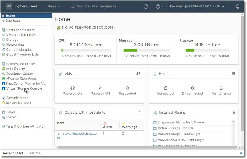
2. Click Provision.
Figure 21 Provisioning Datastore with VSC
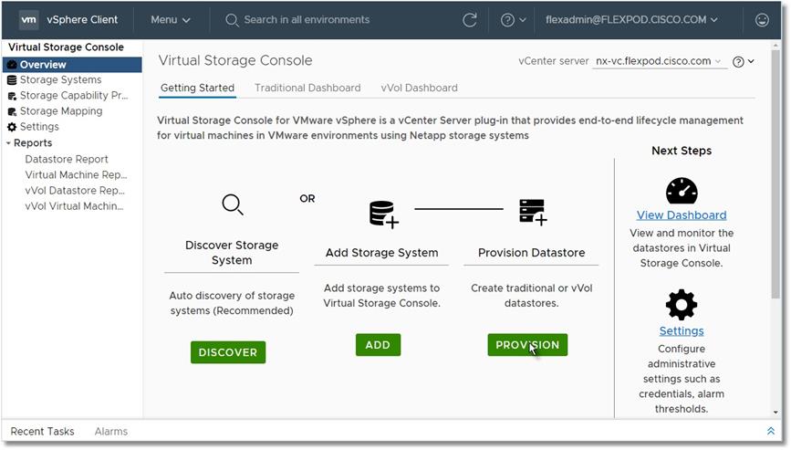
3. Browse to select an available ESXi cluster to provision the datastore.
Figure 22 Creating Volume with VSC
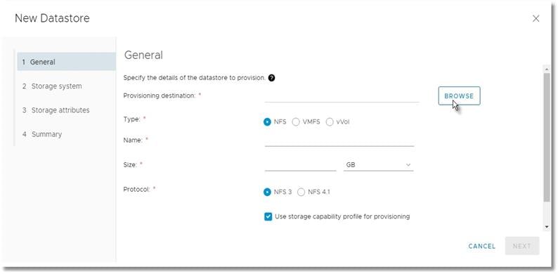
4. Select an appropriate ESXi cluster where the SQL VMs will be deployed in the new datastore.
Figure 23 Selecting ESXi Cluster on VSC
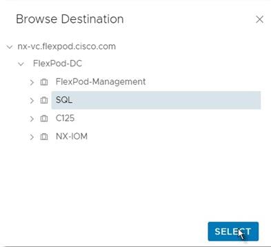
5. Fill in the name of datastore, size and. NFS protocol. Click Next.
Figure 24 Volume Specifications
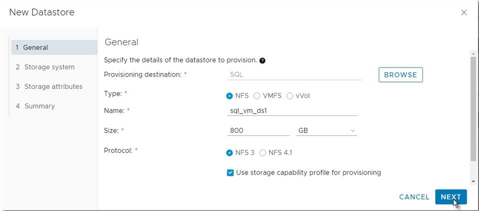
6. Select the storage capability profile, storage system, and storage VM. Click Next.
Figure 25 Volume QoS Specifications
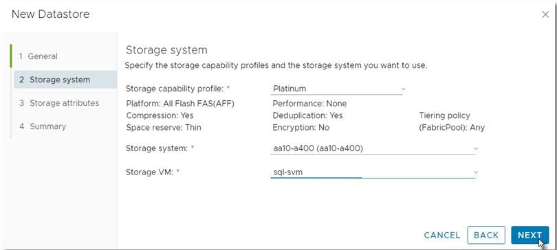
7. Select attributes to provision the storage for FlexVol for the datastore. Click Next.
Figure 26 Selection of NetApp Attributes
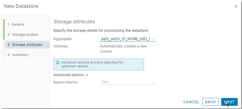
8. Review the Summary and click Finish.
Figure 27 Summary of NetApp Volume Creation using VSC
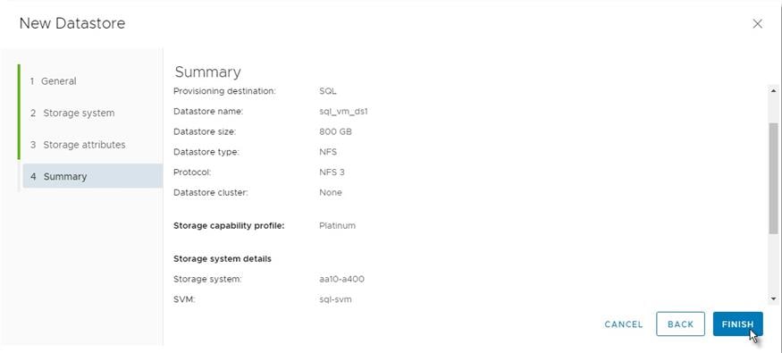
9. After acknowledging the start of the operation, track the progress in vCenter task view.
10. After task is complete, check the datastore configuration in the datastore view of vCenter.
Figure 28 Tracking Status of Volume Creation using VSC
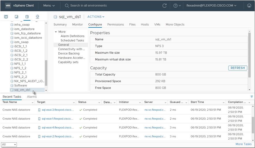
11. Repeat steps 1-10 for one more datastore and select a different aggregate to provision. It is better to distribute the VMs on two datastores residing on different aggregates, so the storage capacity and performance are balanced.
Creating and Deploying Virtual Machines for Hosting SQL Server Databases
This section describes the best practices and recommendations to create and deploy SQL Server Virtual Machines on the FlexPod system.
Cores per Socket
As long as the CPU and memory requirements of a virtual machine is within the single physical socket limits, you do not have to change the default settings “Cores per Socket.” Only when the CPU and memory requirements of a virtual machine is beyond the single physical socket limits, make sure to equally distribute the CPU and memory resources of the virtual machine across the physical sockets.
Also, be careful when customers are using the SQL Server standard edition which supports lesser of 4-sockets or 24 cores. By default, Cores per Socket is set to one and thereby each vCPU is presented as a virtual socket to the virtual machine. For instance, when you assign 6 vCPUs to a virtual machine, the Guest Operating system will have 6 virtual sockets. While configuring vCPUs for virtual machines running SQL Standard edition, ensure that the virtual sockets do not go beyond 4 by adjusting Cores per Socket appropriately.
Memory Reservation
SQL Server database transactions are usually CPU and memory intensive. In a heavy OLTP database systems, it is recommended to reverse all the memory assigned to the SQL Virtual Machines. This makes sure that the assigned memory to the SQL VM is committed and will eliminate the possibility of ballooning and swapping from happening memory reservations will have little overhead on the ESXi system. For more information about memory overhead, refer to Understanding Memory Overhead.
Figure 29 shows a SQL Server Standard Edition virtual machine configuration; only two virtual sockets are configured by adjusting Cores per Socket setting and note that the Memory reservation box is checked.
Figure 29 Cores per Socket and Memory Reservation
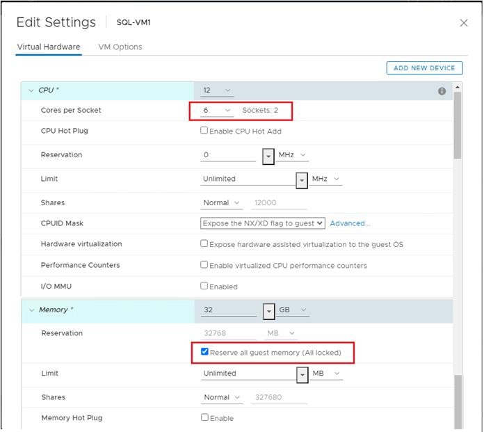
Network Adapter Type
It is highly recommended to configure the virtual machine network adaptors with “VMXNET3.” VMXNET 3 is the latest generation of Paravirtualized NICs designed for performance. It offers several advanced features including multi-queue support, Receive Side Scaling, IPv4/IPv6 offloads, and MSI/MSI-X interrupt delivery.
For this solution, each is SQL virtual machine is configured with three network adapters with VMXNET3 as adapter type. One adapter is connected to the “SQL-MGMT” port group for virtual machine management and SQL access, and the second and third network adapters are connected to the “SQL-iSCSI-A” and “SQL-iSCSI-B” port group respectively. These adapters are used for direct NetApp storage access using third-party software for iSCSI initiator on fabric A and B respectively. Figure 30 shows the SQL virtual machine is configured with three adapters.
Figure 30 Virtual Machine Network Adapter Type and Configuration
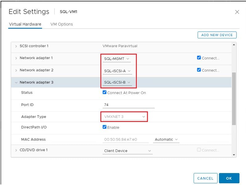
Installing Guest Operating System
This section provides the details about the configuration recommendations for Windows Guest Operating System for hosting SQL Server databases.
For a detailed step-by-step process to install Windows Server 2019 Guest Operating System in the virtual machine, please refer to the VMWare documentation.
![]() When the Windows Guest Operating System is installed in the virtual machine, it is highly recommended to install VMware tools as explained here.
When the Windows Guest Operating System is installed in the virtual machine, it is highly recommended to install VMware tools as explained here.
Guest Power Settings
The default power policy option in Windows Server 2019 is “Balanced.” This configuration allows Windows Server OS to save power consumption by periodically throttling power to the CPU and turning off devices such as the network cards in the guest when Windows Server determines that they are idle or unused. This capability is inefficient for critical SQL Server workloads due to the latency and disruption introduced by the act of powering-off and powering-on CPUs and devices.
For SQL Server database deployments, it is recommended to set the power management option to “High Performance” for optimal database performance as shown in Figure 31.
Figure 31 Windows Guest Power Settings
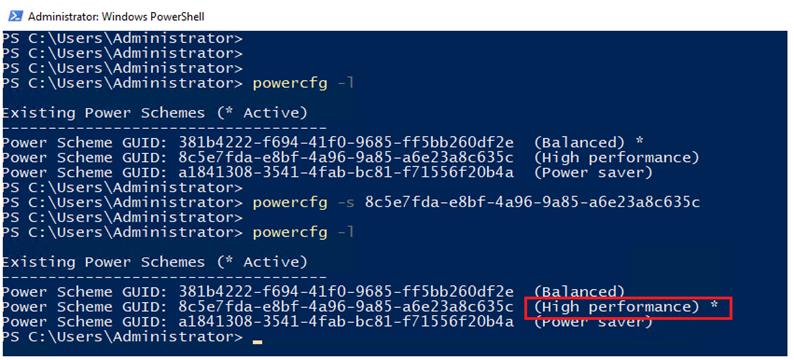
Adding Guest VM to the Domain
It is recommended to change the default Windows Guest VM name and join it to the domain before proceeding with the storage configuration inside the guest virtual machine. For detailed instructions about how to change the Guest name and join the Guest, click here.
Using the server manager, enable the Remote Desktop feature to remotely manage the Guest VM remotely and turn off the firewalls inside the guest VM. Figure 32 shows the final configuration after joining SQLVM3 to the flexpod.cisco.com domain, enabling Remote Desktop, turning off the firewall settings and corresponding IP addresses of management and iSCSI storage interfaces.
Figure 32 Windows Guest Server Configuration
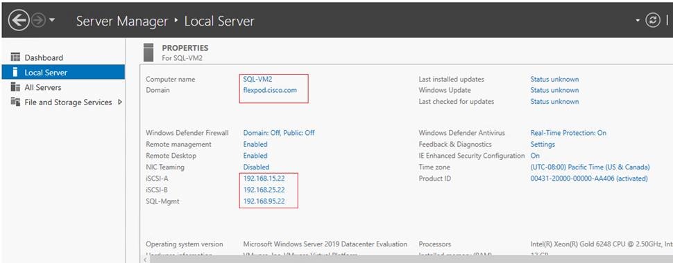
Storage Configuration Inside SQL Virtual Machines
This section details the Guest configuration for jumbo frames, installation and configuration of multipath software, and iSCSI initiator configuration to connect NetApp AFF A400 storage LUNs.
Enabling Jumbo Frames on Storage Network Interfaces
Enabling jumbo frames on the storage traffic provides better IO performance for SQL Server databases. In SQL Guest, make sure that jumbo frames are set to 9000 on the Ethernet Adapter which is used for in-guest iSCSI storage as shown in Figure 33.
Figure 33 Setting Jumbo Frames on Guest Storage Interfaces
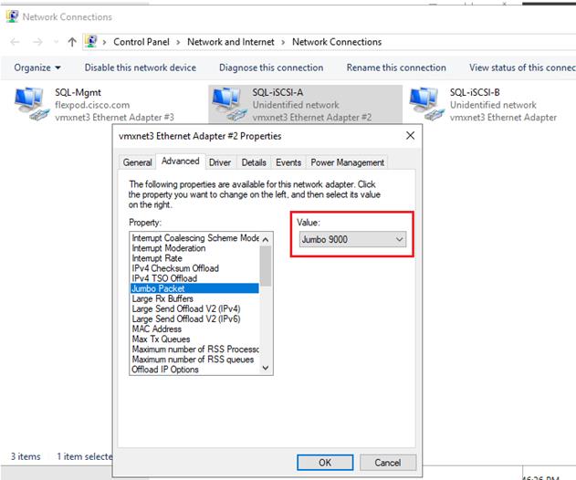
When enabling jumbo frames, make sure the virtual machine is able to reach storage with maximum packet size (8972 bytes) without fragmenting the packets as shown in Figure 34.
Figure 34 Jumbo Frames verification with Storage IPs on the Guest VM
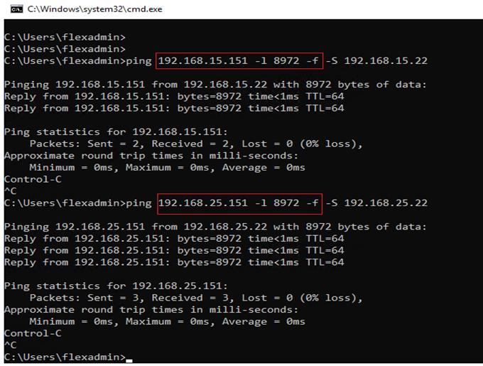
Multipath Software Configuration
NetApp recommends using Windows native multipath drivers for managing storage connections inside the Windows server 2019 Guest VM. Install the Windows native Multipath drivers; Figure 35 shows installing Multipath IO feature using PowerShell. Also, enable Microsoft Device Specific Module (MSDSM) to automatically claim SAN disks for Microsoft Multipath I/O (MPIO) for iSCSI bus type. Restart the virtual machine after the configuration.
Figure 35 Installing Multipath IO Drivers and Enabling iSCSI Devices
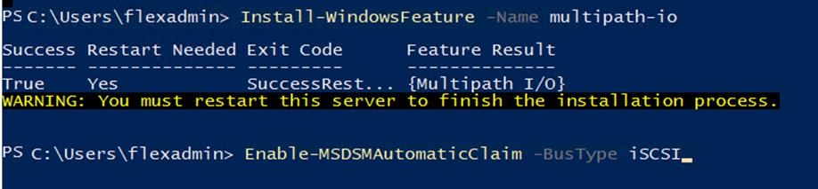
After enabling the MPIO feature in Windows, download and install the NetApp Windows Unified Host Utilities on the virtual machine. To download and install the host utilities, follow these steps:
1. Download the NetApp host utilities v7.1 for Windows from this link:
https://mysupport.netapp.com/documentation/productlibrary/index.html?productID=61343
2. Unzip the file and run the executable file. The NetApp Windows Unified Host Utilities setup wizard is launched and click Next.
3. Click Yes, install support for Multipath IO and click Next.
4. Accept the default destination folder and click Next.
5. Click Next and the click Install to start the installation of host utilities.
6. After the installation is complete, click Finish and restart the computer.
After virtual machine is restarted, verify that appropriate device drivers are added in the MPIO utility as shown in Figure 36.
Figure 36 Verifying the MPIO Setting
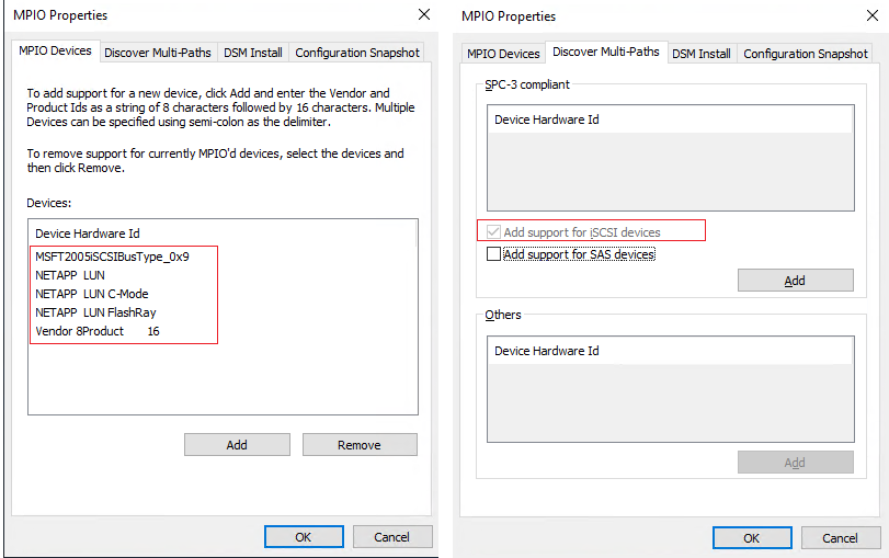
Configuring In-Guest Software iSCSI Initiator
This section provides the steps to configure the in-guest iSCSI initiator for virtual machines to directly access the NetApp storage LUNs.
To configure the in-guest iSCSI initiator, follow these steps:
1. Start the Microsoft iSCSI Initiator service and set it to start automatically as shown below. Get the virtual machine initiator ID name and make a note of it since you will need it for granting the NetApp storage LUN access to the guest virtual machine.
Figure 37 Starting iSCSI Initiator
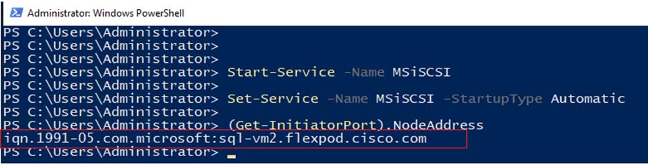
2. Open NetApp ONTAP System Manager and create an initiator group using the iSCSI initiator name as previously noted and is shown below:
Figure 38 Creating iSCSI Initiator Group in the NetApp System Manager
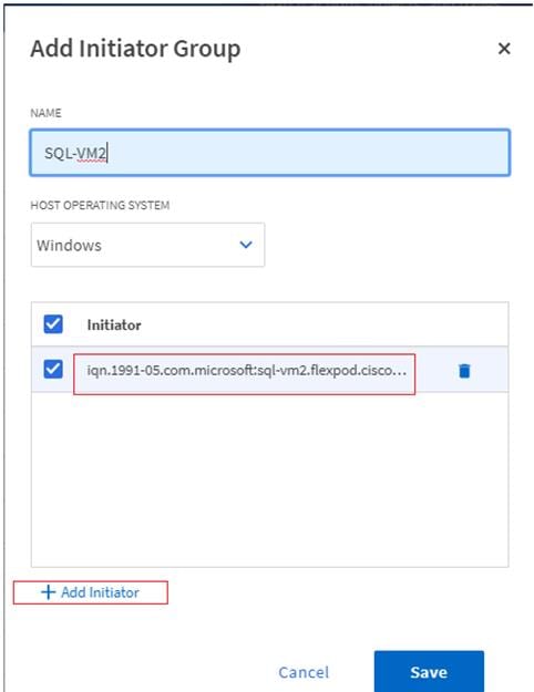
3. When the initiator group for the virtual machines is created, assign the LUNs to the initiator group. The LUN sql_db_5 assigned to the sql-vm2 initiator group Is shown below:
Figure 39 Mapping iSCSI LUNs to the Initiator Group
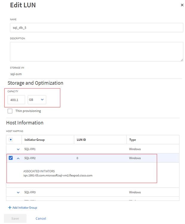
4. When the LUN access is granted to the virtual machine, open the iSCSI initiator inside the Guest VM. On the Discovery tab, click the Discover Target Portal. In the Discover Target Portal, add the target IP address. Repeat this step to include all the target IP addresses as shown below:
Figure 40 Adding iSCSI Target IPs
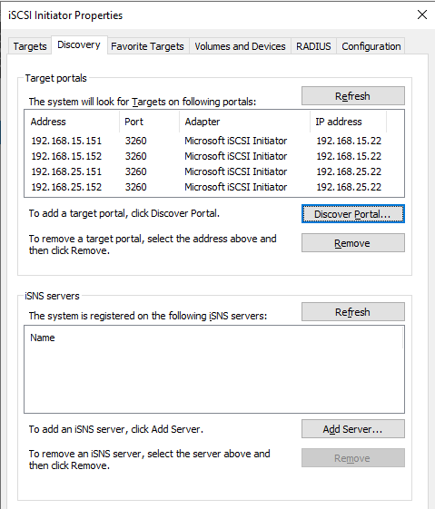
5. Select the Target tab. You will see the NetApp device target IQN under Discovered Targets as shown below:
Figure 41 Discovered Target Device

6. Click Connect to establish an iSCSI session with the discovered NetApp device. In the Connect to Target dialog box, select Enable multi-path checkbox. Click Advanced. In the Advanced Settings dialog box, complete the following steps:
a. On the Local Adapter drop-down list, select Microsoft iSCSI Initiator.
b. On the Initiator IP drop-down list, select the IP address of the SQL Guest.
c. On the Target Portal IP drop-down list, select the IP of Target interface.
d. Click OK to return to the Connect to Target dialog box.
e. Click OK to return to the iSCSI Initiator Properties dialog box.
f. Repeat these steps for all the initiator and target IPs combination.
7. When all the required Initiator and Target connections are established successfully, you can verify the connections by using the following PowerShell command:
Figure 42 Verifying iSCSI Initiator to Target Connections
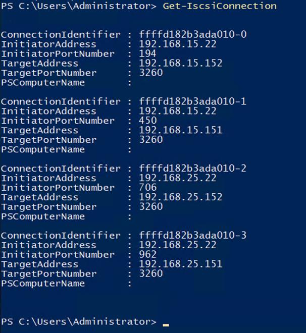
8. Open the Disk management and initialize and format the disks with the NTFS file system and 64K allocation unit size. Under Disk Management, right-click the Disk and select Properties. In the NetApp LUN C-Mode Multi-Path Disk Device Properties dialog box, click the MPIO tab. You should see four storage connections being established; two being Active/Optimized and other two being Active/Unoptimized. These represent the path states defined by the SCSI ALUA (Asymmetric Logical Unit Access) protocol, with the Active/Optimized path being the path to the primary storage controller for the LUN and the Active/Unoptimized being the path to the HA partner controller. The virtual machine using disk management tool is shown below:
Figure 43 Disks in the Disk Management Tool
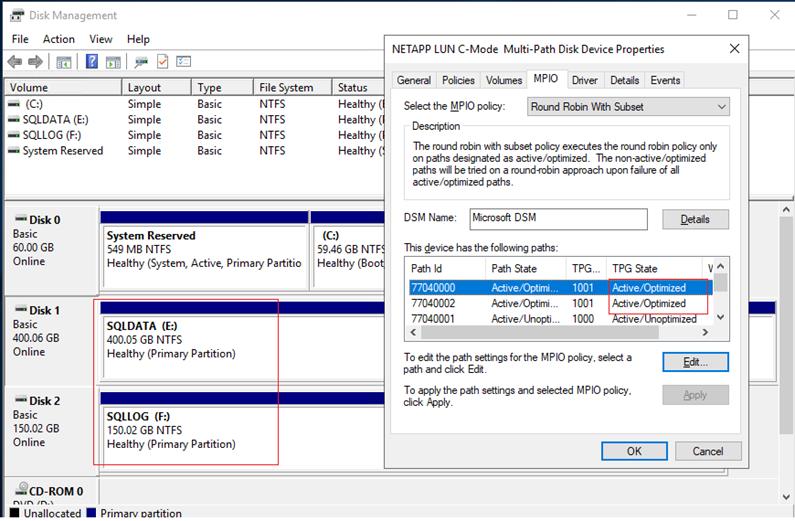
Installing SQL Server and Configuration Recommendations
There are many recommendations and best practices guides available for most of SQL Server settings. But the relevance of these recommendations may vary from one database deployment to another. It is recommended to thoroughly test and validate the critical settings and determine whether or not to implement the specific database environment. The following sections describe some of the key aspects of the SQL Server installation and configurations, which have been used and tested on the FlexPod system. The rest of the SQL Server settings are kept at default and used for performance testing.
Microsoft SQL Server 2019 Installation
This section provides a high-level installation process. For the detailed step-by-step installation for SQL Server 2019 on a Windows Operating system, refer to the Microsoft document: Install SQL Server from the Installation Wizard (Setup).
To install the Microsoft SQL Server 2019, follow these steps:
1. On the Server Configuration window of SQL Server installation, make sure that the instant file initialization is enabled by enabling the checkbox as shown below. This makes sure the SQL server data files are instantly initialized avowing zeroing operations.
Figure 44 Enabling Instant File Initialization of Database Files
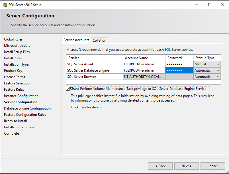
2. In the Database Engine Configuration window under the TempDB tab, make sure the number of TempDB data files are equal to 8 when the vCPUs or logical processors of the SQL VM is less than or equal to 8. If the number of logical processors is more than 8, start with 8 data files and try to add data files in the multiple of 4 when the contention is noticed on the TempDB resources. The following diagram shows that there are 8 TempDB files chosen for a SQL virtual machine which has 8 vCPUs. Also, as a best practice, make sure the TempDB data and log files are two different volumes.
Figure 45 TempDB Files Configuration
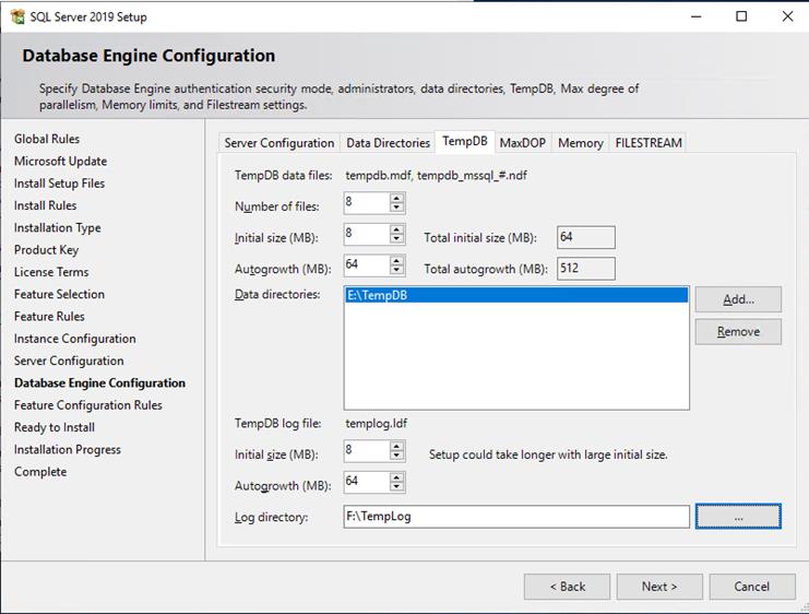
Enable Lock Pages in Option Memory for SQL Server
To enable the lock pages, follow these steps:
1. Make sure to add SQL Server service account is added to “Lock Pages in Memory” policy using the Windows Group Policy editor. Granting the Lock pages in memory user the right to the SQL Server service account prevents SQL Server buffer pool pages from paging out by the Windows Server.
Figure 46 Enabling Lock Pages In Memory Option For SQL Server
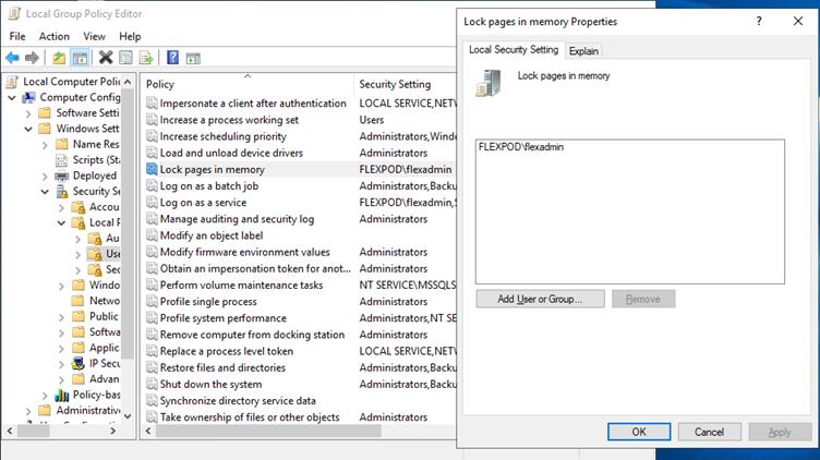
2. A domain account is used as a SQL Server service account which is not a member of the local administrator group, then add SQL Server service account to the “Perform volume maintenance tasks” policy using the Local Security Policy editor.
Max Memory Setting
The SQL Server can consume all the memory allocated to the VM. Setting the Maximum Server Memory allows you to reserve sufficient memory for Operating System and other processes running on the VM. Ideally, you should monitor the overall memory consumption of SQL Server under regular business hours and determine the memory requirements. To start, allow the SQL Server to consume about 80 percent of the total memory or leave at least 2-4GB memory for Operating system. The Maximum Server Memory setting can be dynamically adjusted based on the memory requirements.
Number of Data luns and Database Files
For user databases that have heavy DML operations, it is recommended to create multiple data files of the same size in order to reduce the allocation contention.
If there are high IO demanding workload deployments, use more than one LUN for keeping the database data files. The database performance of such deployments may hit by the queues depths defined at the LUN level both in ESXi environment as well storage level. ONTAP supports a queue depth of 2048 per controller. Queue depths for each client should be configured such that the total possible outstanding commands from all clients does not exceed this limit. For this validation, queue depths were not modified from OS defaults.
For additional SQL Server configuration recommendations, refer to the VMware Architecting Microsoft SQL Server on VMware vSphere® Best Practices Guide.
SnapCenter Configuration for SQL Database Backup, Restore, Cloning and Protection
SnapCenter configuration to prepare for SQL Database operation, includes adding hosts, configuring hosts, provisioning storage to hosts for SQL data and logs, provisioning storage to hosts for SnapCenter logs, creating SQL database resource group(s), and creating backup schedule policy.
Add Hosts (Windows VMs) to SnapCenter
When Hosts are added to SnapCenter, SnapCenter Plug-in for SQL Server and SnapCenter Plug-in for Windows are installed on the host.
To add hosts, follow these steps:
1. Launch SnapCenter Web UI, and login using user account with administrator privilege to SnapCenter.
Figure 47 NetApp SnapCenter Dashboard
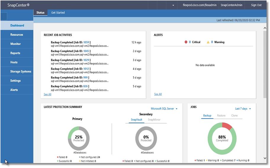
2. Click the Hosts view and click New.
Figure 48 Viewing the Existing SQL Hosts in NetApp SnapCenter
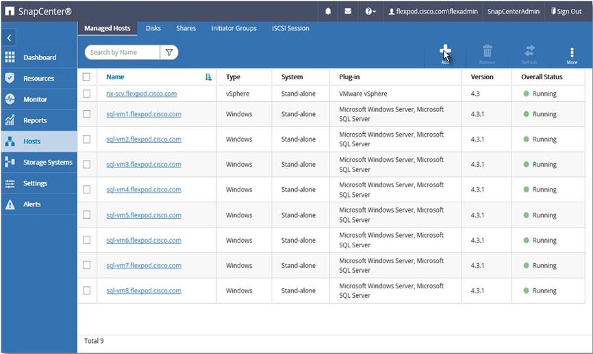
3. Select Host Type Windows, enter the Host Name or IP address and select one of the credentials of administrator user. Select Microsoft Windows and Microsoft SQL Server plug-ins. Optionally, select the port, and/or install path for the plug-in on the host.
Figure 49 Adding New SQL VM Host
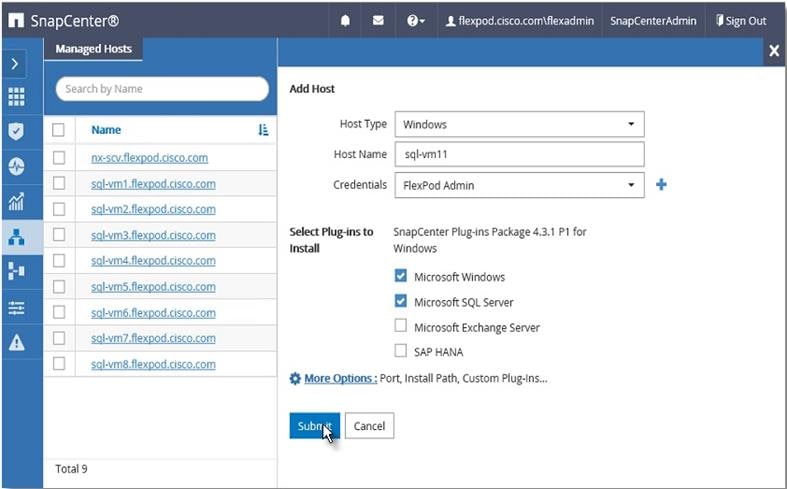
4. After host is added, it will display in the list of Managed Hosts as shown below. Repeat steps 1-3. Newly added hosts will require you to configure the directory for SnapCenter logs for that host.
![]() It is recommended to have a directory for SnapCenter logs on NetApp storage. Prior to configuring the directory for SnapCenter logs, you should provision the storage (LUNs) to the Windows host by following the steps in section Provision storage to Windows VMs using SnapCenter.
It is recommended to have a directory for SnapCenter logs on NetApp storage. Prior to configuring the directory for SnapCenter logs, you should provision the storage (LUNs) to the Windows host by following the steps in section Provision storage to Windows VMs using SnapCenter.
Figure 50 Viewing Newly Added SQL VM Host
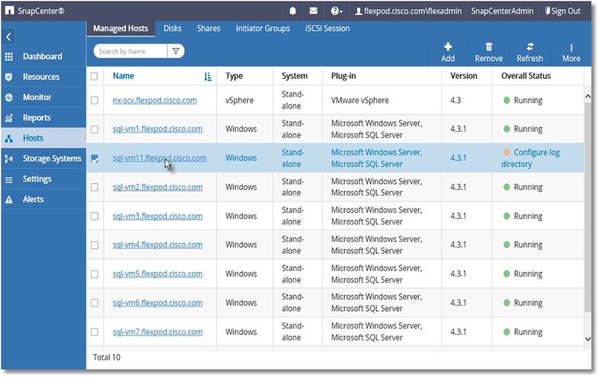
5. Click any of the host names and it will display the Host Details. Click Configure Log Directory.
Figure 51 Configuring SnapCenter Log Directory for SQL VM Host
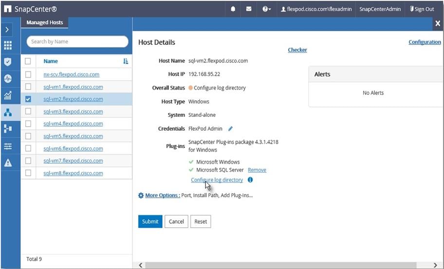
6. Browse to select the SnapCenter Log directory. The log directory should have been created on the drive.
Figure 52 Select LUN for SnapCenter Log Directory
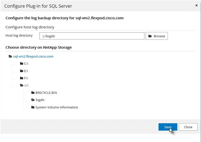
7. The Windows Host is ready for SnapCenter to provision more storage to the host and backup the SQL databases managed by the SQL server running on the host.
Provision Storage to Windows VMs using SnapCenter
SnapCenter can only provision storage LUNs (disk) to Windows VMs that are added to SnapCenter as detailed in the Add Hosts (Windows VMs) to SnapCenter section.
To provision the LUNs (Disks) for SnapCenter log, SQL Database and SQL Logs to the Windows VM, follow these steps:
1. From the SnapCenter Hosts view, click the Disks tab. From the Host drop-down list, select the host you want to provision the storage. Click New to start disk creation wizard.
Figure 53 Provisioning SnapCenter LUN to SQL VM Host
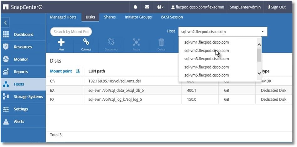
2. Select storage SVM from the Storage System drop-down list. Browse to select the LUN path (Flex volume on SVM). Enter the LUN name. Select the cluster (block) size for Windows File System format, and the label for the Windows File System.
Figure 54 SnapCenter Log LUN Specifications
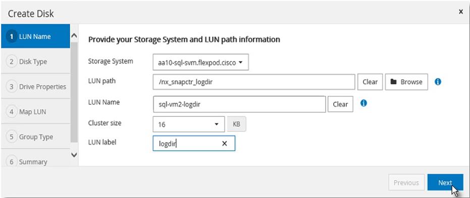
3. For the disk type, select Dedicated, Shared disk, or Cluster Shared Volume (CSV).
Figure 55 SnapCenter Log LUN Access Type
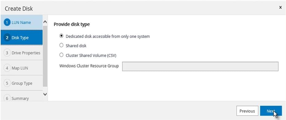
4. Assign drive letter or mount point for the Windows file system mount.
5. Enter drive size and select partition type.
Figure 56 Assigning Drive Letter and Size Specification of SnapCenter Log LUN
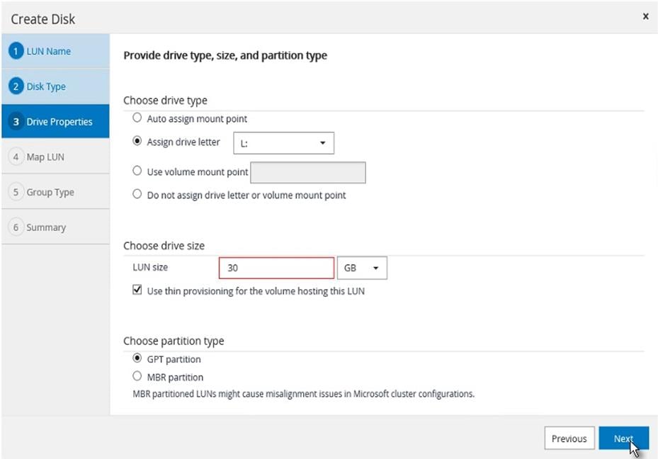
6. Select the initiator to map the LUN (disk). The Initiator already configured on the Windows host is displayed. The iSCSI IQN is available to select after the Software iSCSI initiator is configured on the host, as detailed in section Configuring in-guest software iSCSI initiator.
Figure 57 Selecting In-Guest iSCSI Initiator of SQL VM Host for SnapCenter LUN Mapping
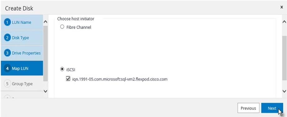
7. When the first LUN (disk) is being provisioned to the Windows Host, select Create new iGroup for selected initiators and provide an iGroup name.
For subsequent disk provisioning to the same host, type the first few letters of the known iGroup for the host and names of all existing iGroups beginning with the entered pattern will display in the drop-down list. The names of the iGroups created by SnapCenter follows the pattern SdwIgroup<VmName> as shown below.
8. Select the existing iGroup name for the host.
Figure 58 Subsequent Disk Provisioning iGroup Specification to the Same Host
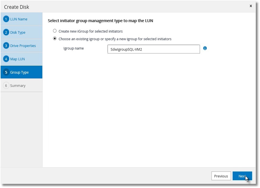
9. Review the Summary and click Finish to complete the disk creation task.
Figure 59 Summary of SnapCenter Log LUN Provisioning
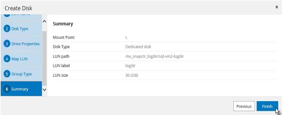
10. SnapCenter will create a LUN on SVM on the NetApp Storage, rescan the disks on the Windows Host, create partition, format file system, and mount at provided Drive letter or Mount Point.
Create Resource Groups
Resource groups are groups of SQL databases and corresponding logs that are backed up together. A backup policy is associated with the resource group to back up the SQL databases and retain a certain number of backups as defined in the policy.
To create resource groups, follow these steps:
1. Launch SnapCenter Web UI. Select Resources view and from the drop-down list select Database. All databases of SQL server instances running on all added hosts will be displayed. Other resource types are SQL Server “Instance”, SQL Server “Availability Group” (AG) and SnapCenter “Resource Group”.
Figure 60 Viewing Resources in SnapCenter
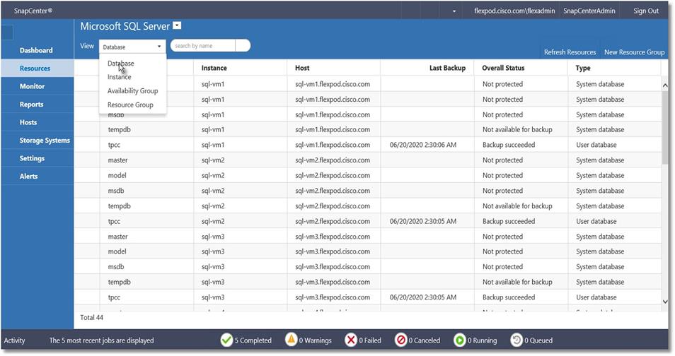
2. Decide which user databases need to be backed up in a group, so they can be added into a single resource group.
3. Select Resource Group from the View drop-down list. Click New Resource Group.
Figure 61 Creating Resource Group using SnapCenter
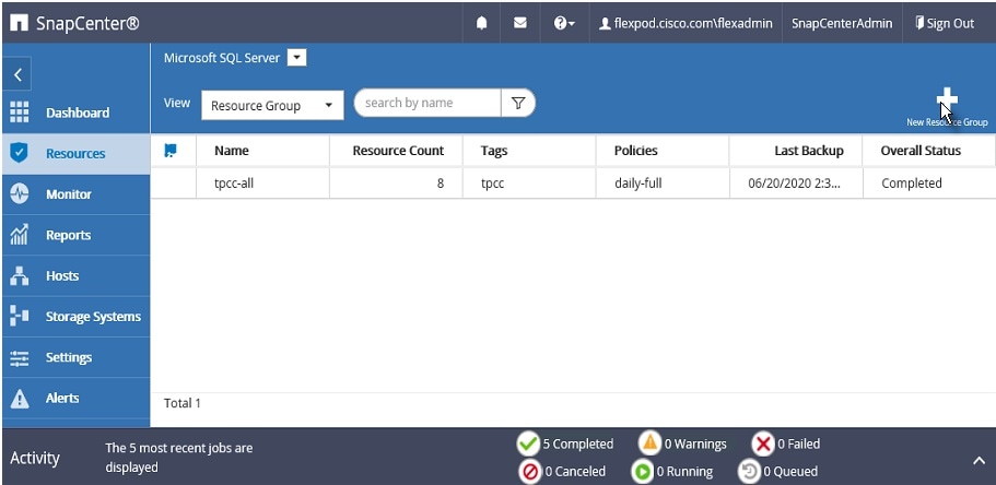
4. Enter the name of the new resource group, any tag for the group and custom name format, if required. The custom name format can contain the resource group name, policy name, schedule name and any custom text entered in the dialog shown below:
Figure 62 Resource Group Specifications
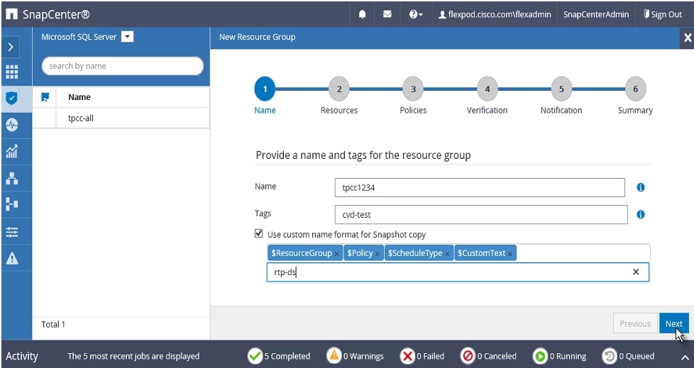
5. Select specific or all hosts, resource type databases, and SQL server instance name from the drop-down list. From the list of databases, select the user databases to add into resource group.
Figure 63 Selecting SQL VM Hosts for the Resource Group
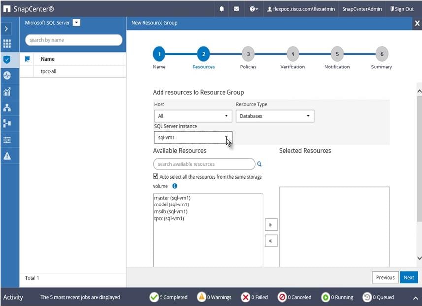
6. Select more databases from the different SQL Server instances if needed, to add those into the same resource group to backup simultaneously according to same policy and schedule.
Figure 64 Selecting Database for Resource Groups
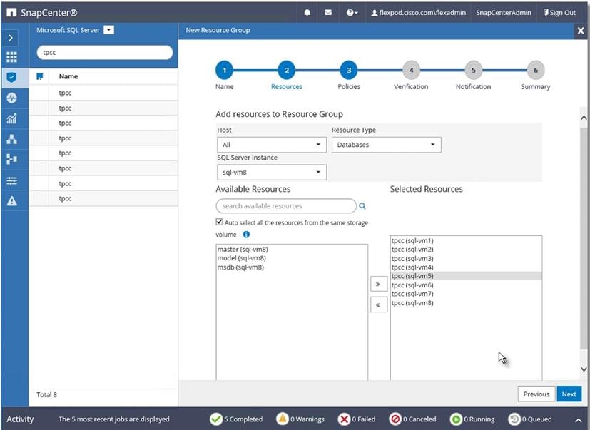
7. Select one or more policies from the drop-down list of available policies or create new policies by clicking ‘+’.
Figure 65 Selecting Policies for Resource Group
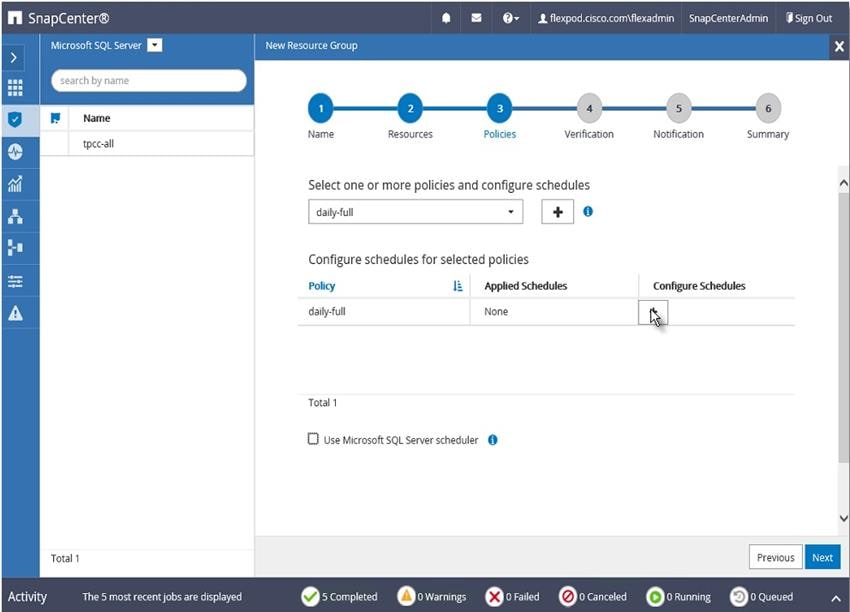
New SQL Server Backup Policy
To create a new SQL server backup policy, follow these steps:
1. In New SQL Server Backup Policy for Resource Group enter a policy name and description. Click Next.
Figure 66 New Backup Policy Name Details
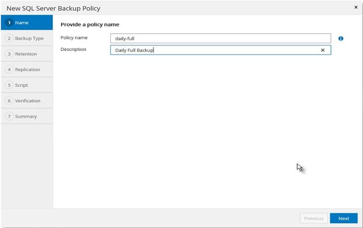
2. Select Backup type and the frequency of the backup. Click Next.
Figure 67 New Backup Policy Specifications
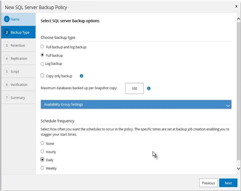
3. Select the retention setting for up-to-the-minute restore operation. Click Next.
Figure 68 New Backup Policy Retention Period Settings
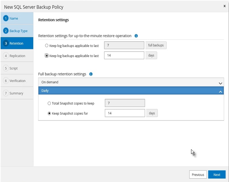
4. Select a replication option, policy label, and enter a number for the retry count for replication attempts. Click Next.
Figure 69 New Backup Policy Specifications
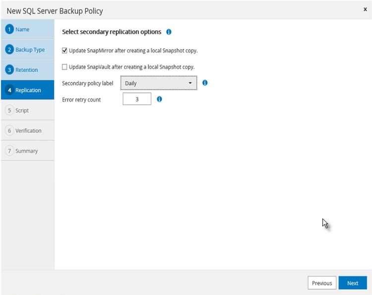
5. Enter the details of the scripts you want to run before and after backup. Click Next.
Figure 70 Pre and Postscripts For New Backup Policy Specifications
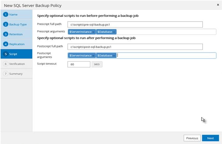
6. Enter the verification schedule details. Click Next.
Figure 71 Frequency of Backup For New Backup Policy
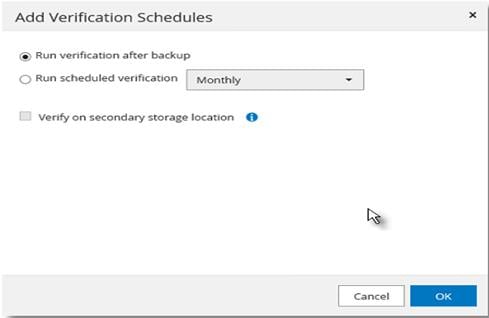
7. Review the Summary of the tasks and click Finish.
Figure 72 Summary of New Backup Policy Creation
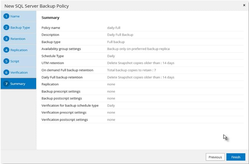
8. Select a Verification server from the drop-down list Click Next.
Figure 73 Specifying Verification SQL VM Host and Scheduling Configuration
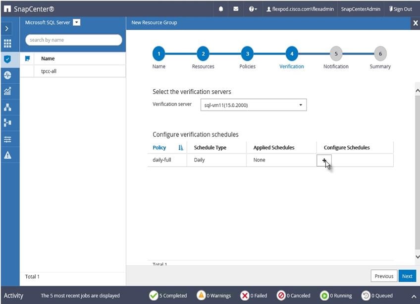
9. Enter a start date, time, and Expires on if it’s required to end the backup schedule on a specific day and time.
Figure 74 Setting Start Time and Expiry Dates
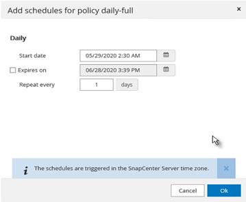
10. Add more policies if needed, then click OK.
Figure 75 Adding Additional Scheduling Policies
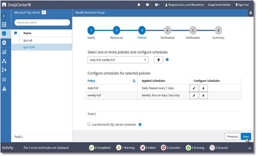
11. In Add Verification Schedules; choose either Run verification after backup or Run scheduled verification and choose a time from the drop-down list. Click OK.
Figure 76 Specifying Verification Schedule
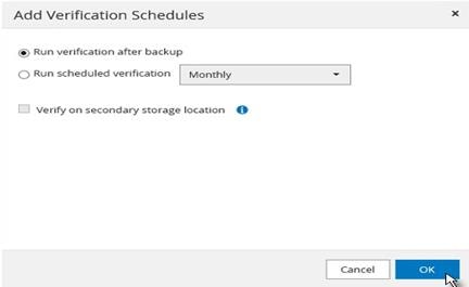
12. To configure Notification, enter the email details and select if the job report should be attached notification emails. Click OK.
Figure 77 Configuring Notifications
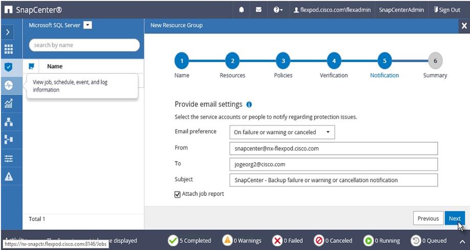
13. Review the Summary and click Finish.
Figure 78 Summary of Resource Group

14. Repeat steps 1-13 if you require additional resource groups .
Figure 79 Resource Groups
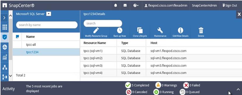
Verify on Demand Backup of SQL Databases
The resource group of SQL databases should have an on-demand backup for the resource group.
To trigger an on-demand backup, follow these steps:
1. Launch SnapCenter Web UI. Select Resources view. Click a Resource group.
2. Click Backup Now.
Figure 80 Triggering Backup Using Resource Group

3. Select a policy to use for the on-demand backup. Select Verify after backup and then click Backup.
Figure 81 Selecting On-Demand Backup time and Verification settings
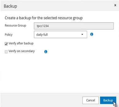
4. Verify the activity status of the triggered backup job as shown below:
Figure 82 Backup Status of Resource Group
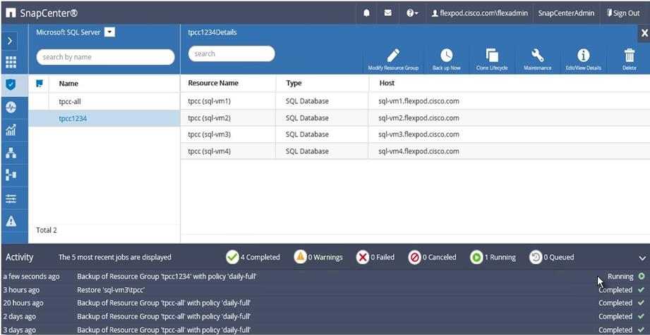
Verify SQL Database Restore from Backup
The section describes the steps to restore the SQL database from backup using NetApp SnapCenter.
Before proceeding, ensure that the backup of the SQL databases Resource group has already been created using SnapCenter.
To restore from database backup, follow these steps:
1. Launch SnapCenter Web UI. Select Resources view. Click a resource view and then click a resource group name.
Figure 83 Resources View

2. Click the name of a database resource to restore from a backup.
Figure 84 Resources View
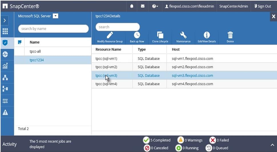
3. The list of backups for the selected resource is displayed. Click the name of the backup to restore the database from.
Figure 85 Select the Backup to Restore Database
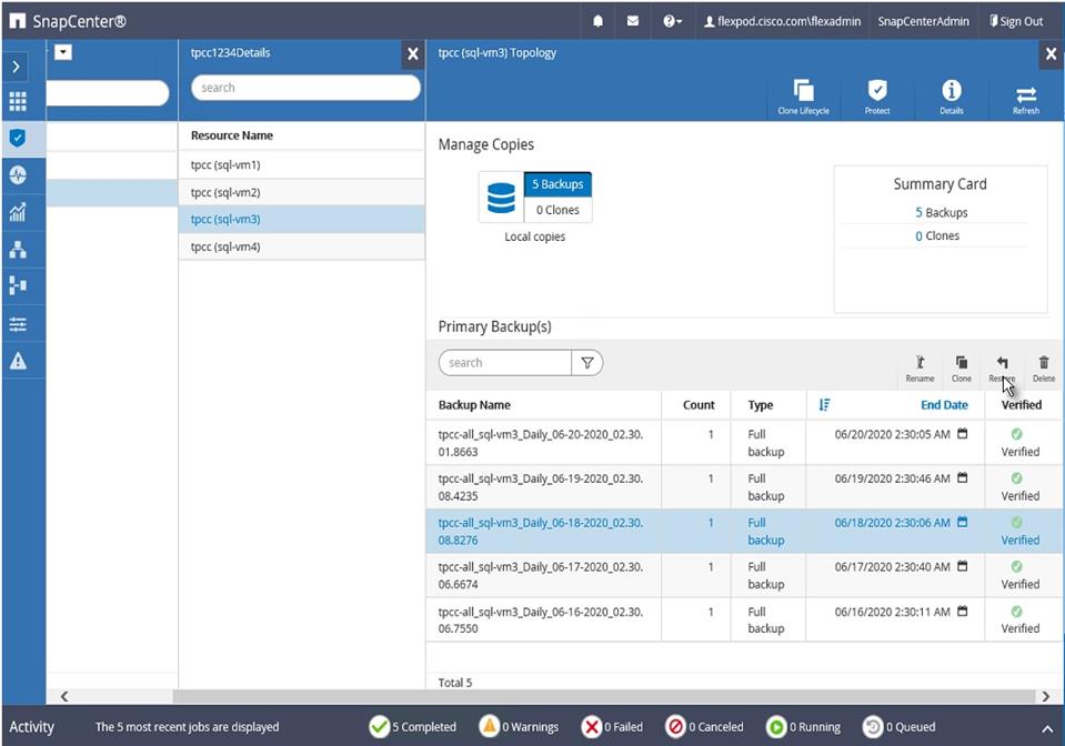
4. Select the host where the database is restored.
Figure 86 Resources Host Selection
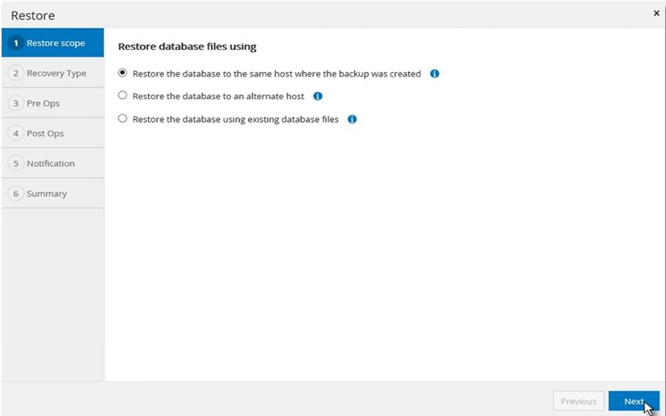
5. Select the desired recovery of logs from backup
Figure 87 Choose Log Backup Recovery
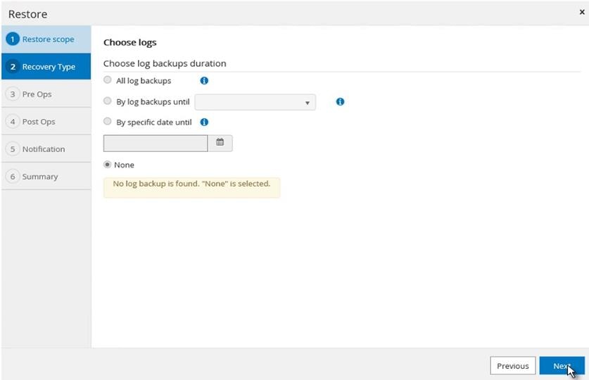
6. Select the pre restore options for the database and the optional script to run before restoring from the backup.
Figure 88 Pre restore Database Options
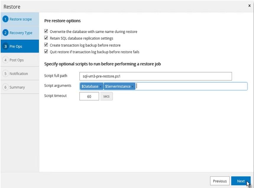
7. Select the post restore options for the database and the optional script to run after restoring from the backup.
Figure 89 Post Restore Database Options
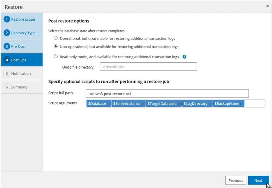
8. Enter notification email details for the restore job.
Figure 90 Restore Job Notification Setting
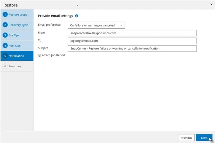
9. Review the Summary of restore task and click Finish.
Figure 91 Restore Task Summary
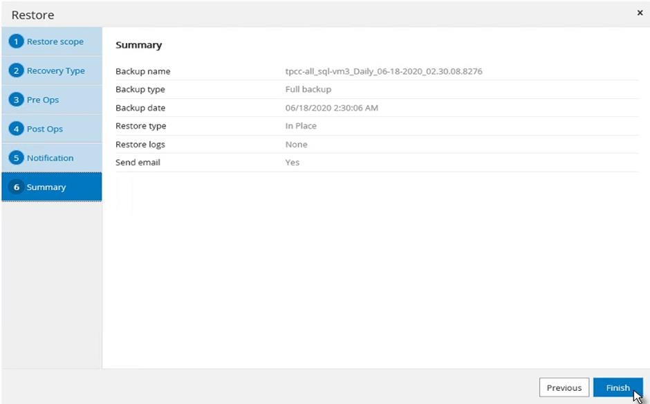
10. Go to the Monitor tab, click Job and enter restore in filter to see job status of restore operation. See details or download the log if needed.
Figure 92 Monitor restore job
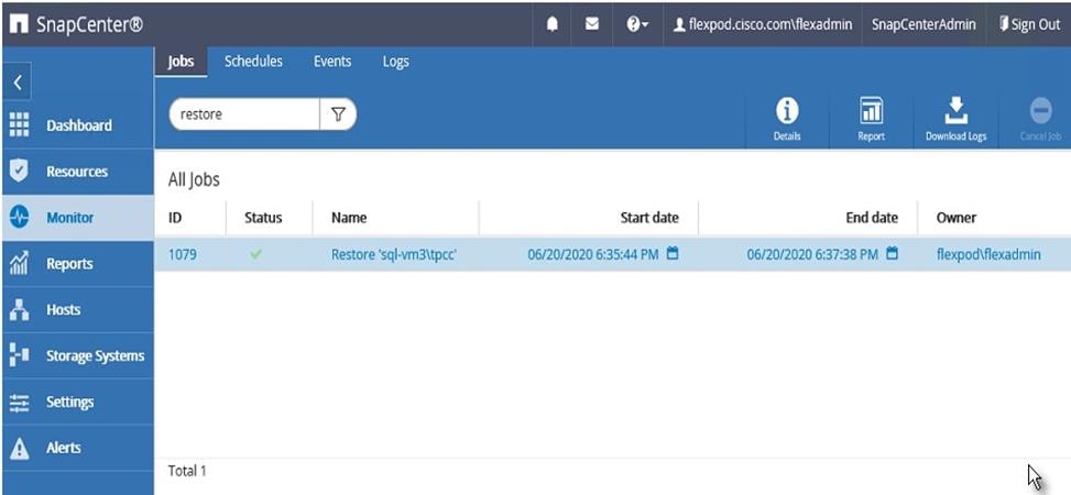
Verify SQL Database Cloning from Backup
The section describes the steps for cloning SQL database from backup using NetApp SnapCenter.
Before proceeding, ensure that the backup of SQL databases Resource group has been created using SnapCenter.
To create a clone of a database from the backup, follow these steps:
1. Launch SnapCenter Web UI. Select Resources view. Click a resource view and click a resource group name.
Figure 93 Resources View
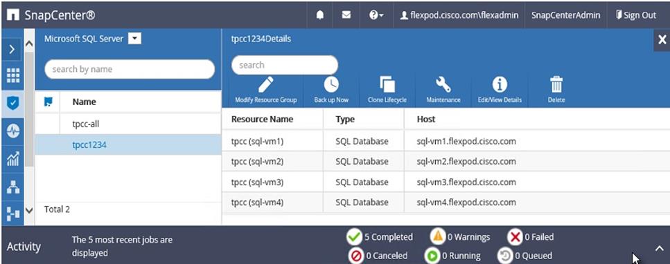
2. Click the name of a database resource to clone from a backup.
Figure 94 Resources View
3. The list of backups for the selected database is displayed. Select the backup to clone the database from, and click Clone.
Figure 95 Select the Backup to Clone Database
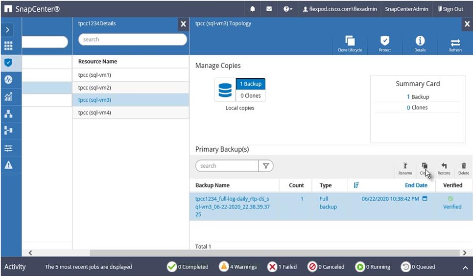
4. Enter clone server, SQL instance, and clone name. Select the option for Windows mountpoint to mount database at.
Figure 96 Enter Database Clone Settings
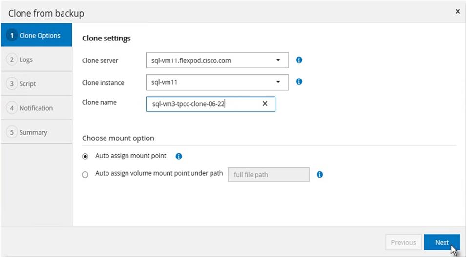
5. Chose log options.
Figure 97 Select Database Clone Log Option
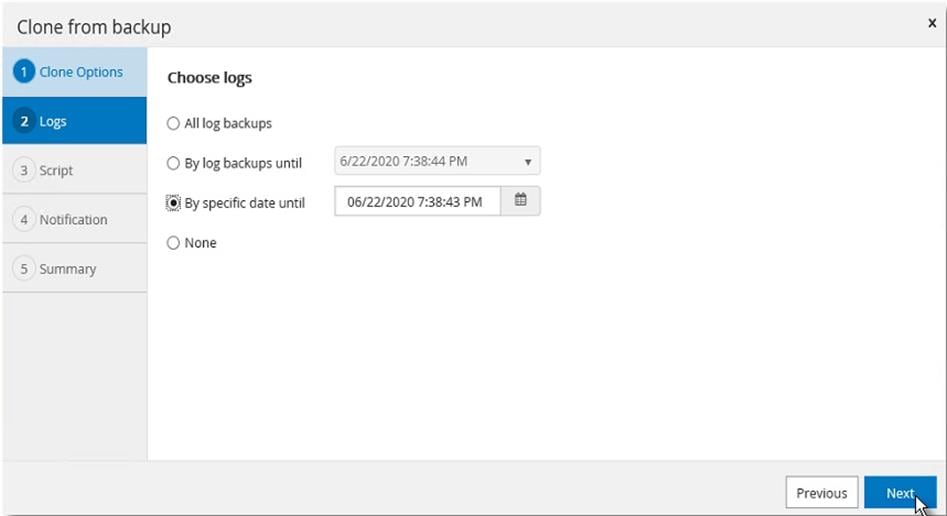
6. Specify the optional pre and post scripts to run before and after clone operation.
Figure 98 Enter Optional Pre-Clone And Post-Clone Script Names
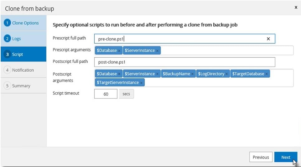
7. Enter the notification email settings for the clone operation notifications.
Figure 99 Notification Email Settings
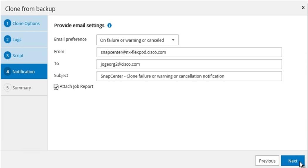
8. Review the Summary of the clone operation to be triggered.
Figure 100 Clone Operation Summary Before Starting the Cloning
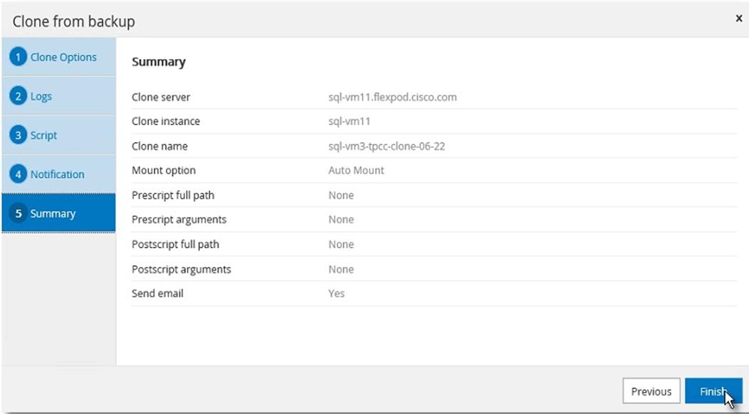
9. Go to Monitor view, click Jobs, and the monitor status of the clone job.
Figure 101 Monitor Clone Job Progress
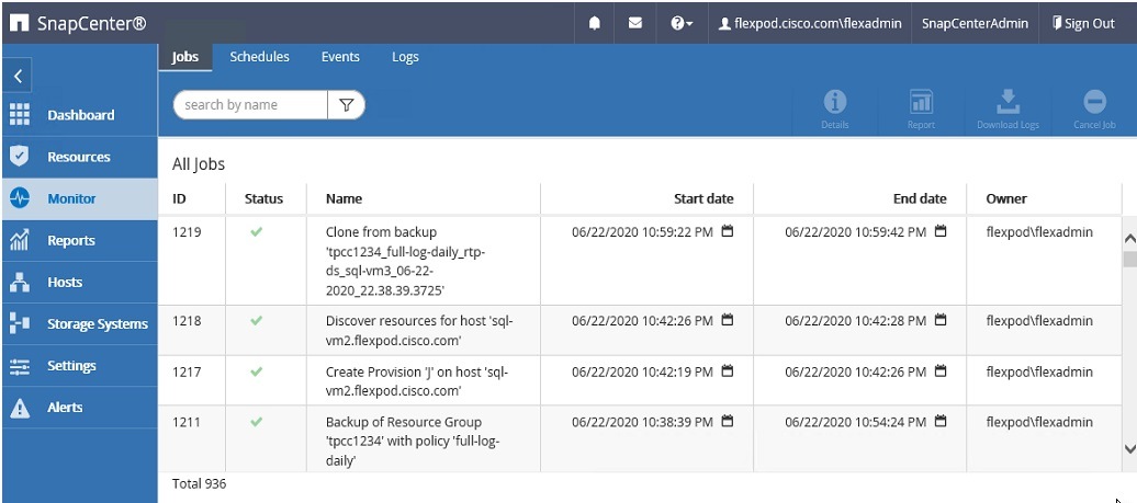
This section describes the solution tests conducted to validate the robustness of the solution. Table 11 lists the complete details of the testbed setup used for conducting various performance tests discussed in the following sections.
Table 11 Hardware and Software Details of Testbed Configuration
| Component |
Device Details |
| Compute |
1x Cisco UCS 5108 blade chassis with 2x Cisco UCS 2408 IO Modules 4x Cisco UCS B200 M5 blades each with one Cisco UCS 1440 VIC adapter |
| Processor Cores per B200 M5 blade |
2x Intel® Xeon® Gold 6248 CPUs, 2.5GHz, 27.5MB L3 cache, 20 Cores per CPU |
| Memory per B200 M5 blade |
384GB (12x 32GB DIMMS operating at 2933MHz) |
| Fabric Interconnects |
2x Cisco UCS 4th Gen 6454 Cisco UCS Manager Firmware: 4.1(1C) |
| Network Switches |
2x Cisco Nexus 9336C-FX2 switches |
| Storage Controllers |
2x NetApp AFF A400 storage controllers with 24 x 1.8TB NVMe SSDs |
| Hypervisor |
VMWare vSphere 6.7 Update 3 |
| Guest Operating System |
Windows 2019 Standard Edition |
| Database software |
SQL Server 2019 Evaluation Edition |
Performance Test Methodology and Results
The FlexPod system is architected from the ground up to offer greater flexibility, scalability, and resiliency to cater to various high-performance and low latency demanding enterprise workloads such as databases, ERP, CRM and BI system, and so on.
In this reference architecture, the FlexPod system is tested and validated with Microsoft SQL Server databases for OLTP (Online Transaction Processing) workloads. Typically, the OLTP workloads are compute-intensive and characterized by a large number of parallel random reads and writes. The FlexPod system, which is built with the combination of Cisco UCS B200 M5 blade servers powered by the latest Intel 2nd Generation scalable processors, 25/100G Fabric Interconnects, and Cisco Nexus switches and NetApp All Flash storage, enable customers to seamlessly consolidate and run many SQL Server databases instances.
This reference architecture demonstrates three aspects of the FlexPod system by hosting multiple SQL server OLTP-like workloads. The following list provides the tests conducted on the FlexPod system:
· Demonstrate database performance scalability for both scale-up and scale-out scenarios using a single Cisco UCS B200 M5 blade server and multiple Cisco UCS B200 M5 blade servers for a 100G database.
· Demonstrate maximum IO capacity of the NetApp AFF A400 storage array.
· Demonstrate NetApp storage snapshots for data protection and quick recovery of databases.
The HammerDB tool is used to simulate an OLTP-like workload at 70:30 read: write ratio on each SQL Server database VM running on the FlexPod system. This tool is installed on a separate client machine and multiple instances of the tool can be started to simulate OLTP like workload on multiple SQL Server virtual machines running on the FlexPod system. At the end of each test, the tool reports the database performance metrics. The performance of each SQL VM is measured using ‘Transactions Per Minute (TPM)’ reported by the tool.
Database Performance Scalability within Single Cisco UCS B200 M5 ESXi Host
The objective of this test is to demonstrate how a single Cisco UCS B200 M5 host can respond as more SQL workload VMs are added to the host.
Table 12 lists the virtual machine configuration and database schema details used for this test. Each virtual machine is configured with 8 vCPUs and 12GB memory. Each SQL VM is stressed at about 65-70 percent of the guest CPU utilization, generating about 23,000 to 25,000 total IO operations at 70:30 read: write ratio.
Table 12 Virtual Machine Configuration Used for Single Cisco UCS B200 Scalability Test
| Component |
Device Details |
| VM Configuration |
8 vCPUs, 12GB Memory (9GB allocated for SQL) |
| Storage Volumes for database |
1 x 400G LUN for Data files 1 x 150GB LUN for T-LOG file |
| Database |
SQL Server 2019 Evaluation Edition |
| Operating System |
Windows 2019 Standard Edition |
| Workload per VM |
Database Size: 100GB Targeted total IOPS: 23000 to 25000 Read: Write Ratio: 70:30% Guest CPU utilization: ~65-70% Performance Metrics collected: Transactions Per Second (TPM/60) Windows Perfmon IO metrics ESXi ESXTOP metrics |
The graph below shows how multiple SQL Server virtual machines perform on a single ESXi host. As shown, a single SQL virtual machine delivered about 8900 Transactions Per Second (TPS). As more SQL virtual machines are added to the same host (up to 4 VMs), the TPS scaled linearly as there are no bottlenecks discovered within the Cisco UCS B200 M5 host as well as NetApp AFF400 storage. With a single SQL virtual machine workload, about 20 percent of ESXi host CPU utilization is noticed. As more virtual machines are added to the host, CPU utilization of the underlying Cisco UCS B200 M5 host is also scaled linearly as shown in below:
Figure 102 Database Performance Scalability with Single Cisco UCS B200 M5 ESXi Host
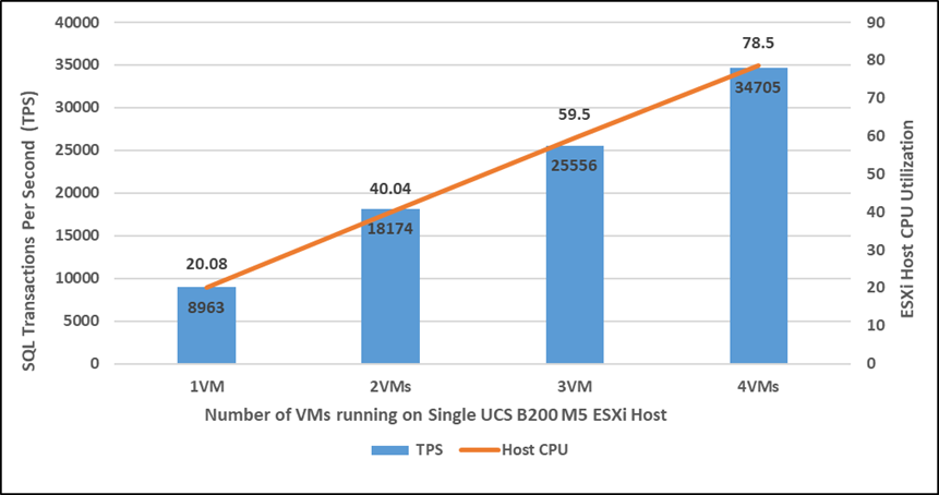
The graph below shows the disk data transfers (IOPS) and latency details for this test. The performance numbers are captured using Windows Perfmon tool at Guest OS level. As shown, a single SQL virtual machine delivered about 24900 IO operations per second (IOPS). As more SQL virtual machines are added to the same host, the IOPS scaled linearly. The write latencies (captured at guest perfmon) stayed within 2 milliseconds.
Figure 103 IOPS Scalability with Single Cisco UCS B200 M5 ESXi Host
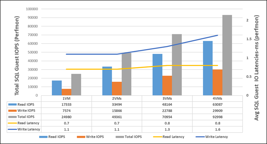
Database Performance Scalability Across the 4x Node ESXi Cluster
The objective of this test is to demonstrate the database performance scalability when multiple SQL VMs are deployed across a four-node ESXi cluster, which is typically seen in real-world implementations.
For this multi-hosts ESXi testing, the same virtual machine configuration and database schema is used in the single ESXi Host testing.
As shown below, a single SQL virtual machine delivered about 8900 Transactions Per Second (TPS). As more SQL virtual machines are added to the cluster (up to 8 VMs), the TPS is scaled linearly as there are no bottlenecks discovered both at compute and storage levels. With a single SQL virtual machine workload, about 20 percent ESXi host CPU utilization is noticed. As more virtual machines are added across the ESXi cluster, CPU utilization of the cluster also scaled near-linearly as shown below:
Figure 104 Database Performance Scalability Across ESXi Cluster
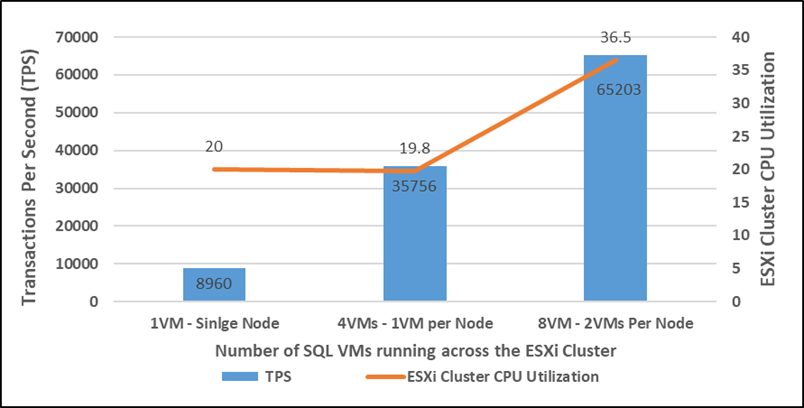
The graph below shows the disk data transfers (IOPS) and latency details for this test. As shown, a single SQL virtual machine delivered about 25000 IO operations per second (IOPS). As more SQL virtual machines are added to the cluster (up to 8 VMs), the IOPS scaled near-linearly. The write latencies (captured at guest perfmon) stayed within 3 milliseconds.
Figure 105 IOPS Scalability Across ESXi Cluster
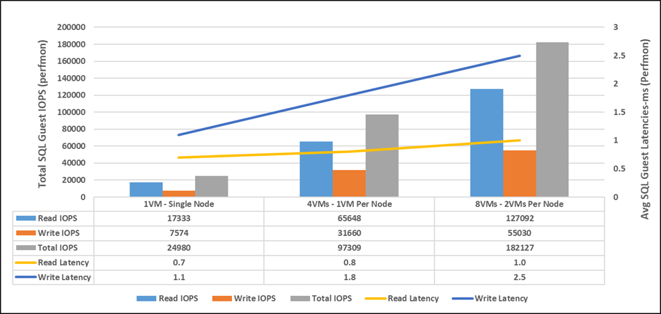
With eight VMs tested across the cluster, NetApp AFF 400 delivered about 180K IOPS with the storage controller’s CPU utilization at about 70 percent. These values indicate that the storage system has not reached the maximum performance threshold and could support additional workloads.
Maximum IO Capacity Testing of NetApp AFF400 Storage Array
The goal of this test is to demonstrate the maximum storage performance that the NetApp AFF 400 storage can deliver for SQL Server database OLTP workloads.
During the performance scalability tests described in the previous sections, the storage subsystem was not stressed to its maximum levels. To test and achieve the maximum storage performance, SQL virtual machines are configured with higher resources to support more database users thereby driving more IOPS. Table 13 lists the VM configuration used for this test.
Table 13 Virtual Machine Configuration for NetApp AFF 400 Maximum Storage Performance Test
| Component |
Device Details |
| VM Configuration |
12 vCPUs, 16GB Memory (10GB allocated for SQL) |
| Storage Volumes for database |
1 x 400G LUN for Data files 1 x 150GB LUN for T-LOG file |
| Database |
SQL Server 2019 Evaluation Edition |
| Operating System |
Windows 2019 Standard Edition |
| Workload per VM |
Database Size: 100GB Number of Users per VM: 45 Targeted total IOPS: 25000 to 28000 Read: Write Ratio: 70:30% Guest CPU utilization: ~65-70% Performance Metrics collected: NetApp Active IQ Manager |
For this test, eight SQL virtual machines are configured and deployed across the four node ESXi cluster. SQL Server databases are stressed using the HammerDB instances running on a separate client machine. The following two graphs show the storage metrics collected using NetApp Active IQ manager during the test. Each SQL virtual machines is stressed up to its 65-70 percent CPU utilization using 45 HammerDB users each contributing 25K to 28K IOPS with 70:30 read write ratio resulted in a total of 230,000 total IOPS at 1.2 ms latency as shown below:
Figure 106 NetApp AFF 400 Storage System Maximum IOPS Test with 70:30 Read Write Ratio
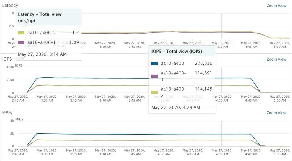
As shown below, the Storage system CPU averaged over 95 percent, indicating that the storage system is at or near its maximum performance capability. While the system could support additional workload that would drive CPU utilization even higher, NetApp recommends that storage systems operate below 80 percent utilization during normal operations to prevent significant performance impact during a controller failure scenario.
Figure 107 Storage System Average CPU Utilization during Maximum IOPS Test
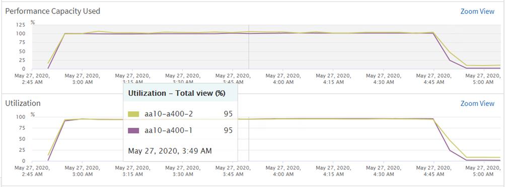
SQL Server Database Workload Monitoring with Cisco Workload Manager (CWOM)
Cisco Workload Optimization Manager is a real-time decision engine that drives continuous health in the IT environment. Its intelligent software constantly analyzes workload consumption, costs, and compliance constraints. It assures application performance by giving workloads the resources they need, when they need them. CWOM provides specific real-time actions that ensure workloads get the resources they need for:
· Placement
· Scaling
· Capacity
Customers can automate the software’s decisions to match their level of comfort:
· Recommended (view only)
· Manual (select and apply)
· Automated (executed in real-time by software)
The remainder of this section focuses on leveraging on-prem CWOM virtual appliance capabilities to monitor SQL Server databases.
CWOM virtual appliance can be downloaded from the Cisco download center site: https://software.cisco.com/download/home/286321574/type/286317011/
For details on deploying CWOM as virtual appliance, refer to: https://www.cisco.com/c/dam/en/us/td/docs/unified_computing/ucs/ucs-workload-optimization-mgr/installation-guide/2-3/cisco-ucs-wom-install-2-3.pdf
A target is a service in a datacenter that can be monitored with CWOM. Currently, wide variety of targets or services can be monitored using CWOM. For details on supported targets and how to configure them, including SQL Server database targets, refer to: https://www.cisco.com/c/dam/en/us/td/docs/unified_computing/ucs/ucs-workload-optimization-mgr/target-configuration/2-3/cisco-ucs-wom-target-config-2-3-13.pdf.
In this CVD, CWOM is leveraged to monitor SQL Server virtual machines running on the FlexPod system. In order to get end-to-end visibility of all the layers of the application stack, required targets like vCenter, Cisco UCS Fabric Interconnects, the NetApp Storage array and SQL Server targets need to be added to the CWOM. All the required targets are added for complete visibility of the FlexPod system, as shown below:
Figure 108 Adding FlexPod Targets to CWOM
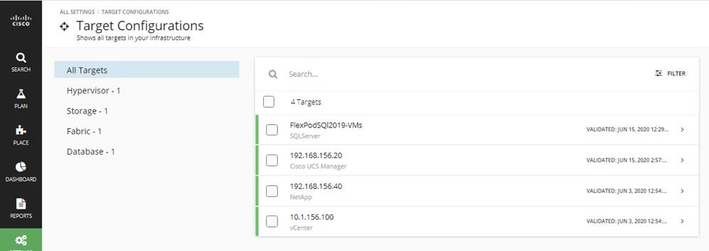
The following figure shows adding a SQL Server target to CWOM. You need to have a SQL Server login account for CWOM to get inventory and utilization data of SQL Server database. In our example below, the SQL Server login “cwom” is used. Ensure the SQL Server login account that CWOM uses has the appropriate rights to the SQL Server databases. “Scope” here indicates the vCenter cluster name of a group of virtual machines running SQL Server databases.
Figure 109 Other CWOM Targets
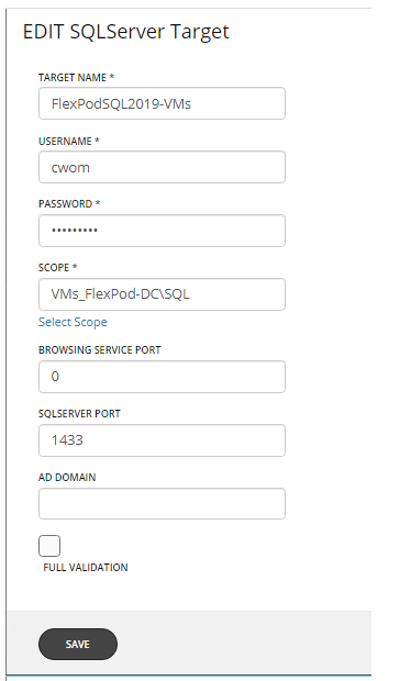
Once the required targets are added to the CWOM, it will contact each target, develop the dependency graph and get the complete inventory, configuration and resource utilization data and provides suggestions using its intelligent recommendation engine.
The complete inventory details of the FlexPod system is shown below. You can click each item and get complete visibility of all the dependent layers.
Figure 110 CWOM Dashboard
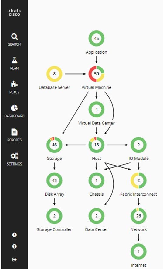
COWM provides a wide variety of recommendations for workloads placement and sizing for optimal SQL Server database performance and efficient infrastructure utilization for on-prem, hybrid and cloud based SQL instances. However, in this document the following SQL Server database specific use cases are discussed.
· CWOM recommendations for underutilized SQL Server databases.
· CWOM recommendations for over-utilized SQL Server database Virtual Machines.
CWOM Recommendations for Underutilized SQL Server Database Virtual Machines
The goal of this test case is to demonstrate what CWOM would recommend when the SQL Server virtual machines resources are underutilized.
For this use case, the following SQL virtual machine configuration is used.
Table 14 SQL Server Virtual Machine Configuration for Underutilized SQL VM
| Component |
Configuration Details |
| VM Configuration |
12 vCPUs, 64GB Memory (60GB allocated for SQL) |
| Storage Volumes for database |
1 x 400G LUN for Data files 1 x 150GB LUN for T-LOG file |
| Database |
SQL Server 2019 Evaluation Edition |
| Operating System |
Windows 2019 Standard Edition |
| Workload |
Tool: HammerDB Database Size: 100GB Working Set: 10% Users: 5 |
The HammerDB tool is used to simulate an OLTP-like workload with 5 users and accessing only 10 percent of the database which does not required to consume all the memory allocated to the SQL instance which will lead to 100 percent cache hit ratio. This is evident that the actual buffer pool usage is observed to be around 34 percent and the remaining allotted memory is unutilized.
In this scenario, CWOM recommends to reduce the memory allocation to the SQL virtual machine, thereby saving the resources which can be made available for other workloads.
Figure 111 CWOM Recommendation for Underutilized SQL Virtual Machines
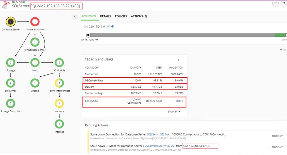
CWOM Recommendations for Overutilized SQL Server Database Virtual Machines
The goal of this use case is to demonstrate what CWOM would recommend if a SQL Server virtual machine is overutilized?
For this use case, the following SQL virtual machine configuration is used.
Table 15 SQL Server Virtual Machine Configuration for Underutilized SQL VM
| Component |
Configuration Details |
| VM Configuration |
2 vCPUs, 6GB Memory (4GB allocated for SQL) |
| Storage Volumes for database |
1 x 400G LUN for Data files 1 x 150GB LUN for T-LOG file |
| Database |
SQL Server 2019 Evaluation Edition |
| Operating System |
Windows 2019 Standard Edition |
| Workload |
Tool: HammerDB Database Size: 100GB Working Set: 100% Users: 30 |
HammerDB tool is used to simulate an OLTP-like workload with 30 users and accessing entire database. Since there is only 4GB available to the SQL Server buffer pool, SQL Server cannot cache the entire data set in it and resulting in accessing new pages from the disk. Therefore, the buffer pool usage is pecked at 100 percent and also driving CPU consumption over 80 percent consistently.
In this scenario, CWOM recommends allocating more memory and CPU resources to the virtual machine as shown below:
Figure 112 CWOM Recommendation for Overutilized SQL Virtual Machines
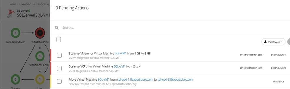
Infrastructure Monitoring with Cisco Intersight
Cisco Intersight™ is a management platform delivered as a service with embedded analytics for your Cisco and 3rd party IT infrastructure. This platform offers an intelligent level of management that enables IT organizations to analyze, simplify, and automate their environments in more advanced ways than the prior generations of tools. Cisco Intersight provides an integrated and intuitive single pane of management experience for resources in the traditional datacenter and at the edge. With flexible deployment options to address complex security needs, getting started with Cisco Intersight is quick and easy.
For more information about Cisco Intersight, refer to: https://www.cisco.com/c/en/us/support/servers-unified-computing/intersight/series.html
Figure 113 shows the server inventory. You can click an individual item and get the server inventory details. Cisco Intersight continuously monitors and provides each component’s health status and can share the technical support details to the Cisco TAC support automatically as a proactive measure.
Figure 113 Cisco Intersight Showing Server Inventory
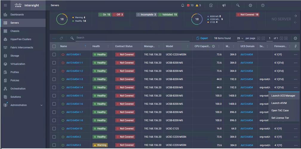
Cisco Intersight can validate Operating System/Hypervisor versions, hardware firmware and driver versions against the Cisco supported versions for each platform and provides recommendation if there are any non-compliance issues. You can quickly review the recommendations and take the necessary actions to make them compliant. Figure 114 shows the Cisco UCS B200 M5 is validated and verified against the Cisco Hardware Compatibility List (HCL).
Figure 114 Intersight Validating Cisco UCS B200 M5 Hardware Compatibility
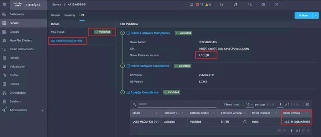
FlexPod is the optimal shared infrastructure foundation to deploy a variety of IT workloads. It is built on leading computing, networking, storage, and infrastructure software components. This CVD is a detailed guide for Microsoft SQL Server 2019 deployment on Windows Server 2019 virtual machines that are deployed in VMware virtual environments.
FlexPod provides a highly efficient data lifecycle management and exceptional storage efficiency for SQL databases and logs.
The performance tests detailed in this document prove the robustness of the solution to host IO sensitive applications such as Microsoft SQL Server for database consolidation and/or peak storage IO use cases.
FlexPod Datacenter with NetApp ONTAP 9.7, Cisco Intersight, and VMware vSphere 6.7 U3:
Cisco UCS VIC Tuning Guide:
Achieve Optimal Network Throughput on the Cisco UCS Virtual Interface Card 1457:
Cisco Workload Optimization Manager:
Gopu Narasimha Reddy, Technical Marketing Engineer, Compute Systems Product Group, Cisco Systems, Inc.
Gopu Narasimha Reddy is a Technical Marketing Engineer in the Cisco UCS Datacenter Solutions group. Currently, he is focusing on developing, testing and validating solutions on the Cisco UCS platform for Microsoft SQL Server databases on Microsoft Windows and VMware platforms. He is also involved in publishing TPC-H database benchmarks on Cisco UCS servers. His areas of interest include building and validating reference architectures, development of sizing tools in addition to assisting customers in SQL deployments.
Sanjeev Naldurgkar, Technical Marketing Engineer, Compute Systems Product Group, Cisco Systems, Inc.
Sanjeev has been with Cisco for eight years focusing on delivering customer-driven solutions on Microsoft Hyper-V and VMware vSphere. He has over 18 years of experience in the IT Infrastructure, server virtualization, and cloud computing. He holds a bachelor’s degree in Electronics and Communications Engineering and leading industry certifications from Microsoft and VMware.
Atul Bhalodia, Sr. Solutions Architect, NetApp Cloud Infrastructure Engineering, NetApp
Atul Bhalodia is a Sr. Solutions Architect with NetApp Cloud Infrastructure Engineering team. He focuses on the Architecture, Deployment, Validation, and documentation of NetApp datacenter and cloud infrastructure solutions. Prior to his current role, he was a Software Development Lead for NetApp SnapDrive and SnapManager Products. Atul has worked in the IT industry for more than 20 years and he holds master’s degree in Computer Engineering from California State University, San Jose, CA.
Acknowledgements
For their support and contribution to the design, validation, and creation of this Cisco Validated Design, the authors would like to thank:
· John George, Cisco Systems, Inc.
· John McAbel, Cisco Systems, Inc.
· Babu Mahadevan, Cisco Systems, Inc.
· AJ Nish, Turbonomic, Inc.