FlexPod Datacenter with Cisco UCS X-Series, VMware 7.0 U2, and NetApp ONTAP 9.9
Available Languages
Bias-Free Language
The documentation set for this product strives to use bias-free language. For the purposes of this documentation set, bias-free is defined as language that does not imply discrimination based on age, disability, gender, racial identity, ethnic identity, sexual orientation, socioeconomic status, and intersectionality. Exceptions may be present in the documentation due to language that is hardcoded in the user interfaces of the product software, language used based on RFP documentation, or language that is used by a referenced third-party product. Learn more about how Cisco is using Inclusive Language.
- US/Canada 800-553-2447
- Worldwide Support Phone Numbers
- All Tools
 Feedback
 Feedback

FlexPod Datacenter with Cisco UCS X-Series, VMware 7.0 U2, and NetApp ONTAP 9.9
Deployment Guide for FlexPod with VMware vSphere 7.0 U2, Cisco UCS X9508 Chassis with Cisco UCS X210c M6 Compute Nodes and Cisco UCS 5108 Chassis with Cisco UCS B200 M6 Blade Servers, deployed using Cisco Intersight Managed Mode, NetApp AFF Storage and NetApp Active IQ Unified Manager
Published: January 2022

In partnership with:
![]()
About the Cisco Validated Design Program
The Cisco Validated Design (CVD) program consists of systems and solutions designed, tested, and documented to facilitate faster, more reliable, and more predictable customer deployments. For more information, go to:
http://www.cisco.com/go/designzone.
ALL DESIGNS, SPECIFICATIONS, STATEMENTS, INFORMATION, AND RECOMMENDATIONS (COLLECTIVELY, "DESIGNS") IN THIS MANUAL ARE PRESENTED "AS IS," WITH ALL FAULTS. CISCO AND ITS SUPPLIERS DISCLAIM ALL WARRANTIES, INCLUDING, WITHOUT LIMITATION, THE WARRANTY OF MERCHANTABILITY, FITNESS FOR A PARTICULAR PURPOSE AND NONINFRINGEMENT OR ARISING FROM A COURSE OF DEALING, USAGE, OR TRADE PRACTICE. IN NO EVENT SHALL CISCO OR ITS SUPPLIERS BE LIABLE FOR ANY INDIRECT, SPECIAL, CONSEQUENTIAL, OR INCIDENTAL DAMAGES, INCLUDING, WITHOUT LIMITATION, LOST PROFITS OR LOSS OR DAMAGE TO DATA ARISING OUT OF THE USE OR INABILITY TO USE THE DESIGNS, EVEN IF CISCO OR ITS SUPPLIERS HAVE BEEN ADVISED OF THE POSSIBILITY OF SUCH DAMAGES.
THE DESIGNS ARE SUBJECT TO CHANGE WITHOUT NOTICE. USERS ARE SOLELY RESPONSIBLE FOR THEIR APPLICATION OF THE DESIGNS. THE DESIGNS DO NOT CONSTITUTE THE TECHNICAL OR OTHER PROFESSIONAL ADVICE OF CISCO, ITS SUPPLIERS OR PARTNERS. USERS SHOULD CONSULT THEIR OWN TECHNICAL ADVISORS BEFORE IMPLEMENTING THE DESIGNS. RESULTS MAY VARY DEPENDING ON FACTORS NOT TESTED BY CISCO.
CCDE, CCENT, Cisco Eos, Cisco Lumin, Cisco Nexus, Cisco StadiumVision, Cisco TelePresence, Cisco WebEx, the Cisco logo, DCE, and Welcome to the Human Network are trademarks; Changing the Way We Work, Live, Play, and Learn and Cisco Store are service marks; and Access Registrar, Aironet, AsyncOS, Bringing the Meeting To You, Catalyst, CCDA, CCDP, CCIE, CCIP, CCNA, CCNP, CCSP, CCVP, Cisco, the Cisco Certified Internetwork Expert logo, Cisco IOS, Cisco Press, Cisco Systems, Cisco Systems Capital, the Cisco Systems logo, Cisco Unified Computing System (Cisco UCS), Cisco UCS B-Series Blade Servers, Cisco UCS C-Series Rack Servers, Cisco UCS S-Series Storage Servers, Cisco UCS Manager, Cisco UCS Management Software, Cisco Unified Fabric, Cisco Application Centric Infrastructure, Cisco Nexus 9000 Series, Cisco Nexus 7000 Series. Cisco Prime Data Center Network Manager, Cisco NX-OS Software, Cisco MDS Series, Cisco Unity, Collaboration Without Limitation, EtherFast, EtherSwitch, Event Center, Fast Step, Follow Me Browsing, FormShare, GigaDrive, HomeLink, Internet Quotient, IOS, iPhone, iQuick Study, LightStream, Linksys, MediaTone, MeetingPlace, MeetingPlace Chime Sound, MGX, Networkers, Networking Academy, Network Registrar, PCNow, PIX, PowerPanels, ProConnect, ScriptShare, SenderBase, SMARTnet, Spectrum Expert, StackWise, The Fastest Way to Increase Your Internet Quotient, TransPath, WebEx, and the WebEx logo are registered trademarks of Cisco Systems, Inc. and/or its affiliates in the United States and certain other countries. (LDW_U3)
All other trademarks mentioned in this document or website are the property of their respective owners. The use of the word partner does not imply a partnership relationship between Cisco and any other company. (0809R)
© 2022 Cisco Systems, Inc. All rights reserved.
Contents
Deployment Hardware and Software
Cisco Intersight Managed Mode Configuration
Storage Configuration – ONTAP Boot Storage Setup
FlexPod Management Tools Setup
The FlexPod Datacenter solution is a validated approach for deploying Cisco and NetApp technologies and products to build shared private and public cloud infrastructure. Cisco and NetApp have partnered to deliver a series of FlexPod solutions that enable strategic data-center platforms. The success of the FlexPod solution is driven through its ability to evolve and incorporate both technology and product innovations in the areas of management, compute, storage, and networking. This document covers deployment details of incorporating the Cisco X-Series modular platform into the FlexPod Datacenter and the ability to manage and orchestrate FlexPod components from the cloud using Cisco Intersight. Some of the key advantages of integrating Cisco UCS X-Series into the FlexPod infrastructure are:
● Simpler and programmable infrastructure: infrastructure as a code delivered through a single partner integrable open API
● Power and cooling innovations: higher power headroom and lower energy loss due to a 54V DC power delivery to the chassis
● Better airflow: midplane-free design with fewer barriers, therefore lower impedance
● Fabric innovations: PCIe/Compute Express Link (CXL) topology for heterogeneous compute and memory composability
● Innovative cloud operations: continuous feature delivery and no need for maintaining on-premise virtual machines supporting management functions
● Built for investment protections: design ready for future technologies such as liquid cooling and high-Wattage CPUs; CXL-ready
In addition to the compute-specific hardware and software innovations, the integration of the Cisco Intersight cloud platform with VMware vCenter and NetApp Active IQ Unified Manager delivers monitoring, orchestration, and workload optimization capabilities for different layers (virtualization and storage) of the FlexPod infrastructure. The modular nature of the Cisco Intersight platform also provides an easy upgrade path to additional services, such as workload optimization and Kubernetes.
This deployment guide also showcases configuring and managing Cisco UCS 5108 chassis equipped with Cisco UCS B200 M6 blades using Cisco Intersight. Both Cisco UCS B200 M6 blades and Cisco UCS X210c compute nodes fit seamlessly in the FlexPod architecture and can be deployed and managed using common server profiles and configuration policies.
Customers interested in understanding the FlexPod design and deployment details, including the configuration of various elements of design and associated best practices, should refer to Cisco Validated Designs for FlexPod, here: https://www.cisco.com/c/en/us/solutions/design-zone/data-center-design-guides/flexpod-design-guides.html.
Introduction
The Cisco Unified Compute System (Cisco UCS) X-Series is a brand-new modular compute system, configured and managed from the cloud. It is designed to meet the needs of modern applications and to improve operational efficiency, agility, and scale through an adaptable, future-ready, modular design. The Cisco Intersight platform is a Software-as-a-Service (SaaS) infrastructure lifecycle management platform that delivers simplified configuration, deployment, maintenance, and support.
Powered by the Cisco Intersight cloud-operations platform, the Cisco UCS X-Series enables the next-generation cloud-operated FlexPod infrastructure that not only simplifies data-center management but also allows the infrastructure to adapt to the unpredictable needs of modern applications as well as traditional workloads. With the Cisco Intersight platform, customers get all the benefits of SaaS delivery and the full lifecycle management of Intersight-connected distributed servers and integrated NetApp storage systems across data centers, remote sites, branch offices, and edge environments. Cisco Intersight can provide uniform management policies for both Cisco UCS X9508 chassis with Cisco UCS X210c M6 compute nodes and Cisco UCS 5108 chassis with Cisco UCS B200 M6 blades in the FlexPod environment.
Audience
The intended audience of this document includes but is not limited to IT architects, sales engineers, field consultants, professional services, IT managers, partner engineering, and customers who want to take advantage of an infrastructure built to deliver IT efficiency and enable IT innovation.
Purpose of this Document
This document provides deployment guidance around incorporating the Cisco Intersight—managed UCS X-Series platform and Cisco UCS B200 M6 blades within FlexPod Datacenter infrastructure. The document covers both configurations and best practices for a successful deployment. This deployment guide also highlights integration of VMware vCenter and NetApp Active IQ Unified Manager to Cisco Intersight to deliver a true cloud-based integrated approach to infrastructure management.
What’s New in this Release?
The following design elements distinguish this version of FlexPod from previous models:
● Integration of Cisco UCS X-Series into FlexPod Datacenter
● Deploying and managing Cisco UCS X9508 chassis equipped with Cisco UCS X210c M6 compute nodes from the cloud using Cisco Intersight
● Deploying and managing Cisco UCS 5108 chassis equipped with Cisco UCS B200 M6 blades using Cisco Intersight
● Integration of Cisco Intersight with NetApp Active IQ Unified Manager for storage monitoring and orchestration
● Integration of Cisco Intersight with VMware vCenter for interacting with, monitoring, and orchestrating the virtual environment
Deployment Hardware and Software
Design Requirements
The FlexPod Datacenter with Cisco UCS and Intersight meets the following general design requirements:
● Resilient design across all layers of the infrastructure with no single point of failure
● Scalable design with the flexibility to add compute capacity, storage, or network bandwidth as needed
● Modular design that can be replicated to expand and grow as the needs of the business grow
● Flexible design that can support different models of various components with ease
● Simplified design with ability to integrate and automate with external automation tools
● Cloud-enabled design which can be configured, managed, and orchestrated from the cloud using GUI or APIs
To deliver a solution which meets all these design requirements, various solution components are connected and configured as covered in the upcoming sections.
The FlexPod Datacenter solution with Cisco UCS and Intersight is built using following hardware components:
● Cisco UCS X9508* Chassis with up to eight Cisco UCS X210c M6 Compute Nodes
● Cisco UCS 5108* Chassis with up to eight Cisco UCS B200 M6 blade servers
● Fourth-generation Cisco UCS 6454 Fabric Interconnects to support 25GbE, and 100GbE connectivity from various components
● High-speed Cisco NX-OS-based Nexus 93180YC-FX3 switching design to support up to 100GE connectivity
● NetApp AFF A400 end-to-end NVMe storage with high-speed Ethernet and (optional) Fibre Channel connectivity
● Cisco MDS 9132T** switches to support Fibre Channel storage configuration
![]() * This document covers Cisco UCS X9508 chassis and Cisco UCS 5108 chassis connected to the same set of fabric interconnect to show common management and compatibility. Customers can choose to deploy either one or both these platforms in their environment depending on their requirements.
* This document covers Cisco UCS X9508 chassis and Cisco UCS 5108 chassis connected to the same set of fabric interconnect to show common management and compatibility. Customers can choose to deploy either one or both these platforms in their environment depending on their requirements.
![]() ** Cisco MDS 9132T and FC connectivity is not needed when implementing IP-based connectivity design supporting iSCSI boot from SAN and NFS.
** Cisco MDS 9132T and FC connectivity is not needed when implementing IP-based connectivity design supporting iSCSI boot from SAN and NFS.
The software components of the solution consist of:
● Cisco Intersight SaaS platform to deploy, maintain and support the FlexPod components
● Cisco Intersight Assist Virtual Appliance to help connect NetApp ONTAP and VMware vCenter with Cisco Intersight
● NetApp Active IQ Unified Manager to monitor and manage the storage and for NetApp ONTAP integration with Cisco Intersight
● VMware vCenter to set up and manage the virtual infrastructure as well as Cisco Intersight integration
FlexPod Datacenter for IP-based Storage Access
Figure 1 shows various hardware components and the network connections for IP-based FlexPod design.
Figure 1. FlexPod Datacenter Physical Topology for IP-based storage access
The reference hardware configuration includes:
● Two Cisco Nexus 93180YC-FX3 Switches in Cisco NX-OS mode provide the switching fabric.
● Two Cisco UCS 6454 Fabric Interconnects (FI) provide the chassis connectivity. One 100 Gigabit Ethernet port from each FI, configured as a Port-Channel, is connected to each Nexus 93180YC-FX3.
● One Cisco UCS X9508 Chassis connects to fabric interconnects using Cisco UCSX 9108-25G Intelligent Fabric Modules (IFMs), where four 25 Gigabit Ethernet ports are used on each IFM to connect to the appropriate FI. If additional bandwidth is required, all eight 25G ports can be utilized.
● One Cisco UCS 5108 Chassis connects to fabric interconnects using Cisco UCS 2408 Fabric Extender (FEX), where four 25 Gigabit Ethernet ports are used on each FEX to connect to the appropriate FI. If additional bandwidth is required, all eight 25G ports can be utilized.
● One NetApp AFF A400 HA pair connects to the Cisco Nexus 93180YC-FX3 Switches using four 25 GE ports from each controller configured as a Port-Channel.
FlexPod Datacenter for FC-based Storage Access
Figure 2 shows various hardware components and the network connections for FC-based FlexPod design.
Figure 2. FlexPod Datacenter Physical Topology for FC-based storage access
The reference hardware configuration includes:
● Two Cisco Nexus 93180YC-FX3 Switches in Cisco NX-OS mode provide the switching fabric.
● Two Cisco UCS 6454 Fabric Interconnects (FI) provide the chassis connectivity. One 100 Gigabit Ethernet port from each FI, configured as a Port-Channel, is connected to each Nexus 93180YC-FX3. Two FC ports are connected to the Cisco MDS 9132T switches using 32-Gbps Fibre Channel connections configured as a single port channel for SAN connectivity.
● One Cisco UCS X9508 Chassis connects to fabric interconnects using Cisco UCSX 9108-25G Intelligent Fabric Modules (IFMs), where four 25 Gigabit Ethernet ports are used on each IFM to connect to the appropriate FI. If additional bandwidth is required, all eight 25G ports can be utilized.
● One Cisco UCS 5108 Chassis connects to fabric interconnects using Cisco UCS 2408 Fabric Extender (FEX), where four 25 Gigabit Ethernet ports are used on each FEX to connect to the appropriate FI. If additional bandwidth is required, all eight 25G ports can be utilized.
● One NetApp AFF A400 HA pair connects to the Cisco Nexus 93180YC-FX3 Switches using four 25 GE ports from each controller configured as a Port-Channel. One 32Gbps FC port from each controller is connected to each Cisco MDS 9132T for SAN connectivity.
![]() The NetApp storage controller and disk shelves should be connected according to best practices for the specific storage controller and disk shelves. For disk shelf cabling, refer to NetApp Support: https://docs.netapp.com/us-en/ontap-systems/index.html
The NetApp storage controller and disk shelves should be connected according to best practices for the specific storage controller and disk shelves. For disk shelf cabling, refer to NetApp Support: https://docs.netapp.com/us-en/ontap-systems/index.html
Table 1 lists VLANs configured for setting up the FlexPod environment along with their usage.
| VLAN ID |
Name |
Usage |
IP Subnet used in this deployment |
| 2 |
Native-VLAN |
Use VLAN 2 as native VLAN instead of default VLAN (1). |
|
| 3072 |
OOB-MGMT-VLAN |
Out-of-band management VLAN to connect management ports for various devices |
10.81.72.0/24; GW: 10.81.72.254 |
| 17 |
IB-MGMT-VLAN |
In-band management VLAN utilized for all in-band management connectivity - for example, ESXi hosts, VM management, and so on. |
192.168.17.0/24; GW: 192.168.17.254 |
| 172 |
VM-Traffic |
VM data traffic VLAN |
10.1.72.0/24; GW: 10.1.72.254 |
| 3017 |
NFS-VLAN |
NFS VLAN for mounting datastores in ESXi servers for VMs |
192.168.30.0/24 ** |
| 3117* |
iSCSI-A |
iSCSI-A path for storage traffic including boot-from-san traffic |
192.168.31.0/24 ** |
| 3217* |
iSCSI-B |
iSCSI-B path for storage traffic including boot-from-san traffic |
192.168.32.0/24 ** |
| 3317 |
vMotion |
VMware vMotion traffic |
192.168.33.0/24 ** |
* iSCSI VLANs are not required if using FC storage access.
** IP gateway is not needed since no routing is required for these subnets
Some of the key highlights of VLAN usage are as follows:
● VLAN 3072 allows customers to manage and access out-of-band management interfaces of various devices.
● VLAN 17 is used for in-band management of VMs, ESXi hosts, and other infrastructure services
● VLAN 3017 provides ESXi hosts access to the NSF datastores hosted on the NetApp Controllers for deploying VMs.
● A pair of iSCSI VLANs (3117 and 3217) is configured to provide access to boot LUNs for ESXi hosts. These VLANs are not needed if customers are using FC-only connectivity.
● VLAN 3317 is used for VM vMotion
Table 2 lists the infrastructure VMs necessary for deployment as outlined in this document.
| Virtual Machine Description |
VLAN |
IP Address |
Comments |
| vCenter Server |
|
10.81.72.101 |
Hosted on pre-existing management infrastructure |
| NetApp ONTAP Tools |
17 |
192.168.17.8 |
Hosted on FlexPod |
| NetApp SnapCenter for vSphere |
17 |
192.168.17.10 |
Hosted on FlexPod |
| Active IQ Unified Manager |
17 |
192.168.17.9 |
Hosted on FlexPod |
| Cisco Intersight Assist |
|
10.81.72.99 |
Hosted on pre-existing management Infrastructure |
Table 3 lists the software revisions for various components of the solution.
| Layer |
Device |
Image Bundle |
Comments |
| Compute |
Cisco UCS |
4.2(1h) |
Cisco UCS X-series GA release for infrastructure including FIs and IOM/IFM. |
| Network |
Cisco Nexus 93180YC-FX3 NX-OS |
9.3(8) |
|
|
|
Cisco MDS 9132T |
8.4(2c) |
|
| Storage |
NetApp AFF A400 |
ONTAP 9.9.1P2 |
|
| Software |
Cisco UCS X210c |
5.0(1b) |
Cisco UCS X-series GA release for compute nodes |
|
|
Cisco UCS B200 M6 |
4.2(1b) |
|
|
|
Cisco Intersight Assist Appliance |
1.0.9-342 |
|
|
|
VMware vSphere |
7.0 Update 2b |
|
|
|
VMware ESXi nfnic FC Driver |
5.0.0.15 |
Supports FC-NVMe |
|
|
VMware ESXi nenic Ethernet Driver |
1.0.35.0 |
|
|
|
NetApp ONTAP Tools for VMware vSphere |
9.8P1 |
Formerly Virtual Storage Console (VSC) |
|
|
NetApp NFS Plug-in for VMware VAAI |
2.0 |
|
|
|
NetApp SnapCenter for vSphere |
4.5 |
Includes the vSphere plug-in for SnapCenter |
|
|
NetApp Active IQ Unified Manager |
9.9P1 |
|
Physical Connectivity
Follow the physical connectivity guidelines for FlexPod as explained in section Physical Topology.
Initial Configuration
The following procedures describe this basic configuration of the Cisco Nexus switches for use in the FlexPod environment. This procedure assumes the use of Cisco Nexus 9000 9.3(8), the Cisco suggested Nexus switch release at the time of this validation.
Set Up Initial Configuration
To set up the initial configuration for the Cisco Nexus A switch on <nexus-A-hostname>, follow these steps from a serial console:
1. Configure the switch.
![]() On initial boot, the NX-OS setup should automatically start and attempt to enter Power on Auto Provisioning.
On initial boot, the NX-OS setup should automatically start and attempt to enter Power on Auto Provisioning.
Abort Power On Auto Provisioning [yes - continue with normal setup, skip - bypass password and basic configuration, no - continue with Power On Auto Provisioning] (yes/skip/no)[no]: yes
Disabling POAP.......Disabling POAP
poap: Rolling back, please wait... (This may take 5-15 minutes)
---- System Admin Account Setup ----
Do you want to enforce secure password standard (yes/no) [y]: Enter
Enter the password for "admin": <password>
Confirm the password for "admin": <password>
Would you like to enter the basic configuration dialog (yes/no): yes
Create another login account (yes/no) [n]: Enter
Configure read-only SNMP community string (yes/no) [n]: Enter
Configure read-write SNMP community string (yes/no) [n]: Enter
Enter the switch name: <nexus-A-hostname>
Continue with Out-of-band (mgmt0) management configuration? (yes/no) [y]: Enter
Mgmt0 IPv4 address: <nexus-A-out_of_band_mgmt0-ip>
Mgmt0 IPv4 netmask: <nexus-A-mgmt0-netmask>
Configure the default gateway? (yes/no) [y]: Enter
IPv4 address of the default gateway: <nexus-A-mgmt0-gw>
Configure advanced IP options? (yes/no) [n]: Enter
Enable the telnet service? (yes/no) [n]: Enter
Enable the ssh service? (yes/no) [y]: Enter
Type of ssh key you would like to generate (dsa/rsa) [rsa]: Enter
Number of rsa key bits <1024-2048> [1024]: Enter
Configure the ntp server? (yes/no) [n]: Enter
Configure default interface layer (L3/L2) [L2]: Enter
Configure default switchport interface state (shut/noshut) [noshut]: shut
Enter basic FC configurations (yes/no) [n]: n
Configure CoPP system profile (strict/moderate/lenient/dense) [strict]: moderate
Would you like to edit the configuration? (yes/no) [n]: Enter
2. Review the configuration summary before enabling the configuration.
Use this configuration and save it? (yes/no) [y]: Enter
To set up the initial configuration of the Cisco Nexus B switch, repeat the steps above with appropriate host and IP address information.
Cisco Nexus A and Cisco Nexus B
1. Log in as admin using ssh.
2. Run the following commands:
config t
feature nxapi
feature udld
feature interface-vlan
feature lacp
feature vpc
feature lldp
Cisco Nexus A and Cisco Nexus B
To set global configurations, follow this step on both switches:
1. Run the following commands to set global configurations:
spanning-tree port type network default
spanning-tree port type edge bpduguard default
spanning-tree port type edge bpdufilter default
port-channel load-balance src-dst l4port
ntp server <global-ntp-server-ip> use-vrf management
ntp master 3
clock timezone <timezone> <hour-offset> <minute-offset>
(For Example: clock timezone EST -5 0)
clock summer-time <timezone> <start-week> <start-day> <start-month> <start-time> <end-week> <end-day> <end-month> <end-time> <offset-minutes>
(For Example: clock summer-time EDT 2 Sunday March 02:00 1 Sunday November 02:00 60)
copy run start
![]() For more information on configuring the timezone and daylight savings time or summer time, please see Cisco Nexus 9000 Series NX-OS Fundamentals Configuration Guide, Release 9.3(x).
For more information on configuring the timezone and daylight savings time or summer time, please see Cisco Nexus 9000 Series NX-OS Fundamentals Configuration Guide, Release 9.3(x).
Cisco Nexus A and Cisco Nexus B
To create the necessary virtual local area networks (VLANs), follow this step on both switches:
1. From the global configuration mode, run the following commands:
vlan <oob-mgmt-vlan-id for example, 3072>
name oob-mgmt
vlan <ib-mgmt-vlan-id for example, 17>
name ib-mgmt
vlan <native-vlan-id for example, 2>
name Native-Vlan
vlan <vmotion-vlan-id for example, 3317>
name vmotion
vlan <vm-traffic-vlan-id for example, 172>
name vm-traffic
vlan <infra-nfs-vlan-id for example, 3017>
name nfs-vlan
2. If configuring iSCSI storage access, create following two additional VLANs:
vlan <iscsi-a-vlan-id for example, 3117>
name iscsi-a
vlan <iscsi-b-vlan-id for example, 3217>
name iscsi-b
Cisco Nexus A and Cisco Nexus B
To create the necessary port channels between devices, follow these steps on both switches:
1. From the global configuration mode, run the following commands:
interface Po10
description vPC peer-link
interface Eth1/53-54
channel-group 10 mode active
no shutdown
!
! UCS Connectivity
!
interface Po11
description <ucs-hostname>-a
!
interface Eth1/49
channel-group 11 mode active
no shutdown
!
interface Po12
description <ucs-hostname>-b
!
interface Eth1/50
channel-group 12 mode active
no shutdown
!
! Storage Connectivity
!
interface Po13
description <st-clustername>-01
!
interface Eth1/17-18
channel-group 13 mode active
no shutdown
!
interface Po14
description <st-clustername>-02
!
interface Eth1/19-20
channel-group 14 mode active
no shutdown
!
! Management Switch Connectivity
!
interface Po17
description MGMT-Uplink
!
interface Eth1/47
channel-group 17 mode active
no shutdown
exit
copy run start
Configure Port Channel Parameters
Cisco Nexus A and Cisco Nexus B
To configure port channel parameters, follow this step on both switches.
![]() iSCSI VLANs in these steps are only configured when setting up iSCSI storage access.
iSCSI VLANs in these steps are only configured when setting up iSCSI storage access.
1. From the global configuration mode, run the following commands to setup VPC Peer-Link port-channel:
interface Po10
switchport mode trunk
switchport trunk native vlan <native-vlan-id>
switchport trunk allowed vlan <oob-mgmt-vlan-id>, <ib-mgmt-vlan-id>, <infra-nfs-vlan-id>, <vmotion-vlan-id>, <vm-traffic-vlan-id>, <iscsi-a-vlan-id>, <iscsi-b-vlan-id>
spanning-tree port type network
speed 100000
duplex full
2. From the global configuration mode, run the following commands to setup port-channels for UCS FI 6454 connectivity:
interface Po11
switchport mode trunk
switchport trunk native vlan <native-vlan-id>
switchport trunk allowed vlan <oob-mgmt-vlan-id>, <ib-mgmt-vlan-id>, <infra-nfs-vlan-id>, <vmotion-vlan-id>, <vm-traffic-vlan-id>, <iscsi-a-vlan-id>, <iscsi-b-vlan-id>
spanning-tree port type edge trunk
mtu 9216
!
interface Po12
switchport mode trunk
switchport trunk native vlan <native-vlan-id>
switchport trunk allowed vlan <oob-mgmt-vlan-id>, <ib-mgmt-vlan-id>, <infra-nfs-vlan-id>, <vmotion-vlan-id>, <vm-traffic-vlan-id>, <iscsi-a-vlan-id>, <iscsi-b-vlan-id>
spanning-tree port type edge trunk
mtu 9216
3. From the global configuration mode, run the following commands to setup port-channels for NetApp A400 connectivity:
interface Po13
switchport mode trunk
switchport trunk native vlan <native-vlan-id>
switchport trunk allowed vlan <ib-mgmt-vlan-id>, <infra-nfs-vlan-id>, <iscsi-a-vlan-id>, <iscsi-b-vlan-id>
spanning-tree port type edge trunk
mtu 9216
!
interface Po14
switchport mode trunk
switchport trunk native vlan <native-vlan-id>
switchport trunk allowed vlan <ib-mgmt-vlan-id>, <infra-nfs-vlan-id>, <iscsi-a-vlan-id>, <iscsi-b-vlan-id>
spanning-tree port type edge trunk
mtu 9216
4. From the global configuration mode, run the following commands to setup port-channels for connectivity to existing management switch:
interface Po17
switchport mode trunk
switchport trunk native vlan <native-vlan-id>
switchport trunk allowed vlan <oob-mgmt-vlan-id>, <ib-mgmt-vlan-id>
spanning-tree port type network
mtu 9216
!
exit
copy run start
For fibre-optic connections between Cisco UCS Fabric Interconnects and Cisco Nexus 93180YC-FX3 switches, UDLD configuration is automatically enabled, and no additional configuration is required on either device.
Configure Virtual Port Channels
Cisco Nexus A
To configure virtual port channels (vPCs) for switch A, follow this step:
1. From the global configuration mode, run the following commands:
vpc domain <nexus-vpc-domain-id for example, 10>
role priority 10
peer-keepalive destination <nexus-B-mgmt0-ip> source <nexus-A-mgmt0-ip>
peer-switch
peer-gateway
auto-recovery
delay restore 150
ip arp synchronize
!
interface Po10
vpc peer-link
!
interface Po11
vpc 11
!
interface Po12
vpc 12
!
interface Po13
vpc 13
!
interface Po14
vpc 14
!
interface Po17
vpc 17
!
exit
copy run start
Cisco Nexus B
To configure vPCs for switch B, follow this step:
1. From the global configuration mode, run the following commands:
vpc domain <nexus-vpc-domain-id for example, 10>
role priority 20
peer-keepalive destination <nexus-A-mgmt0-ip> source <nexus-B-mgmt0-ip>
peer-switch
peer-gateway
auto-recovery
delay restore 150
ip arp synchronize
!
interface Po10
vpc peer-link
!
interface Po11
vpc 11
!
interface Po12
vpc 12
!
interface Po13
vpc 13
!
interface Po14
vpc 14
!
interface Po17
vpc 17
!
exit
copy run start
See the following section (NetApp Hardware Universe) for planning the physical location of the storage systems:
● Site Preparation
● System Connectivity Requirements
● Circuit Breaker, Power Outlet Balancing, System Cabinet Power Cord Plugs, and Console Pinout Requirements
● AFF Series Systems
To confirm that the hardware and software components that you would like to use are supported with the version of ONTAP that you plan to install, follow these steps at the NetApp Support site.
1. Access the HWU application to view the System Configuration guides. Click the Platforms menu to view the compatibility between different version of the ONTAP software and the NetApp storage appliances with your desired specifications.
2. Alternatively, to compare components by storage appliance, click Compare Storage Systems.
Follow the physical installation procedures for the controllers found here: https://docs.netapp.com/us-en/ontap-systems/index.html.
NetApp storage systems support a wide variety of disk shelves and disk drives. The complete list of disk shelves that are supported by the AFF A400 and AFF A800 is available at the NetApp Support site.
When using SAS disk shelves with NetApp storage controllers, refer to: https://docs.netapp.com/us-en/ontap-systems/sas3/index.html for proper cabling guidelines.
When using NVMe drive shelves with NetApp storage controllers, refer to: https://docs.netapp.com/us-en/ontap-systems/ns224/index.html for installation and servicing guidelines.
NetApp ONTAP 9.9.1P2
Complete Configuration Worksheet
Before running the setup script, complete the Cluster setup worksheet in the ONTAP 9 Documentation Center. You must have access to the NetApp Support site to open the cluster setup worksheet.
Before running the setup script, review the configuration worksheets in the Software setup section of the ONTAP 9 Documentation Center to learn about configuring ONTAP. Table 4 lists the information needed to configure two ONTAP nodes. Customize the cluster-detail values with the information applicable to your deployment.
Table 4. ONTAP Software Installation Prerequisites
| Cluster Detail |
Cluster Detail Value |
| Cluster node 01 IP address |
<node01-mgmt-ip> |
| Cluster node 01 netmask |
<node01-mgmt-mask> |
| Cluster node 01 gateway |
<node01-mgmt-gateway> |
| Cluster node 02 IP address |
<node02-mgmt-ip> |
| Cluster node 02 netmask |
<node02-mgmt-mask> |
| Cluster node 02 gateway |
<node02-mgmt-gateway> |
| ONTAP 9.9 URL (http server hosting ONTAP software) |
<url-boot-software> |
Configure Node 01
To configure node 01, follow these steps:
1. Connect to the storage system console port. You should see a Loader-A prompt. However, if the storage system is in a reboot loop, press Ctrl-C to exit the autoboot loop when the following message displays:
Starting AUTOBOOT press Ctrl-C to abort…
2. Allow the system to boot up.
autoboot
3. Press Ctrl-C when prompted.
![]() If ONTAP 9.9.1P2 is not the version of software being booted, continue with the following steps to install new software. If ONTAP 9.9.1P2 is the version being booted, choose option 8 and y to reboot the node. Then continue with section Set Up Node.
If ONTAP 9.9.1P2 is not the version of software being booted, continue with the following steps to install new software. If ONTAP 9.9.1P2 is the version being booted, choose option 8 and y to reboot the node. Then continue with section Set Up Node.
4. To install new software, select option 7 from the menu.
5. Enter y to continue the installation.
6. Select e0M for the network port for the download.
7. Enter n to skip the reboot.
8. Select option 7 from the menu: Install new software first
9. Enter y to continue the installation
10. Enter the IP address, netmask, and default gateway for e0M.
Enter the IP address for port e0M: <node01-mgmt-ip>
Enter the netmask for port e0M: <node01-mgmt-mask>
Enter the IP address of the default gateway: <node01-mgmt-gateway>
11. Enter the URL where the software can be found.
![]() The e0M interface should be connected to management network and the web server must be reachable (using ping) from node 01.
The e0M interface should be connected to management network and the web server must be reachable (using ping) from node 01.
<url-boot-software>
12. Press Enter for the user name, indicating no user name.
13. Enter y to set the newly installed software as the default to be used for subsequent reboots.
14. Enter yes to reboot the node.
![]() When installing new software, the system might perform firmware upgrades to the BIOS and adapter cards, causing reboots and possible stops at the Loader-A prompt. If these actions occur, the system might deviate from this procedure.
When installing new software, the system might perform firmware upgrades to the BIOS and adapter cards, causing reboots and possible stops at the Loader-A prompt. If these actions occur, the system might deviate from this procedure.
![]() During the ONTAP installation a prompt to reboot the node requests a Y/N response. The prompt requires the entire Yes or No response to reboot the node and continue the installation.
During the ONTAP installation a prompt to reboot the node requests a Y/N response. The prompt requires the entire Yes or No response to reboot the node and continue the installation.
15. Press Ctrl-C when the following message displays:
Press Ctrl-C for Boot Menu
16. Select option 4 for Clean Configuration and Initialize All Disks.
17. Enter y to zero disks, reset config, and install a new file system.
18. Enter yes to erase all the data on the disks.
![]() The initialization and creation of the root aggregate can take 90 minutes or more to complete, depending on the number and type of disks attached. When initialization is complete, the storage system reboots. Note that SSDs take considerably less time to initialize. You can continue with the configuration of node 02 while the disks for node 01 are zeroing.
The initialization and creation of the root aggregate can take 90 minutes or more to complete, depending on the number and type of disks attached. When initialization is complete, the storage system reboots. Note that SSDs take considerably less time to initialize. You can continue with the configuration of node 02 while the disks for node 01 are zeroing.
Configure Node 02
To configure node 02, follow these steps:
1. Connect to the storage system console port. You should see a Loader-B prompt. However, if the storage system is in a reboot loop, press Ctrl-C to exit the autoboot loop when the following message displays:
Starting AUTOBOOT press Ctrl-C to abort…
2. Allow the system to boot up.
autoboot
3. Press Ctrl-C when prompted.
![]() If ONTAP 9.9.1P2 is not the version of software being booted, continue with the following steps to install new software. If ONTAP 9.9.1 is the version being booted, choose option 8 and y to reboot the node, then continue with section Set Up Node.
If ONTAP 9.9.1P2 is not the version of software being booted, continue with the following steps to install new software. If ONTAP 9.9.1 is the version being booted, choose option 8 and y to reboot the node, then continue with section Set Up Node.
4. To install new software, select option 7.
5. Enter y to continue the installation.
6. Select e0M for the network port you want to use for the download.
7. Enter n to skip the reboot.
8. Select option 7: Install new software first
9. Enter y to continue the installation
10. Enter the IP address, netmask, and default gateway for e0M.
Enter the IP address for port e0M: <node02-mgmt-ip>
Enter the netmask for port e0M: <node02-mgmt-mask>
Enter the IP address of the default gateway: <node02-mgmt-gateway>
11. Enter the URL where the software can be found.
![]() The web server must be reachable (ping) from node 02.
The web server must be reachable (ping) from node 02.
<url-boot-software>
12. Press Enter for the username, indicating no user name.
13. Enter y to set the newly installed software as the default to be used for subsequent reboots.
14. Enter yes to reboot the node.

![]() When installing new software, the system might perform firmware upgrades to the BIOS and adapter cards, causing reboots and possible stops at the Loader-A prompt. If these actions occur, the system might deviate from this procedure.
When installing new software, the system might perform firmware upgrades to the BIOS and adapter cards, causing reboots and possible stops at the Loader-A prompt. If these actions occur, the system might deviate from this procedure.
![]() During the ONTAP installation a prompt to reboot the node requests a Y/N response. The prompt requires the entire Yes or No response to reboot the node and continue the installation.
During the ONTAP installation a prompt to reboot the node requests a Y/N response. The prompt requires the entire Yes or No response to reboot the node and continue the installation.
15. Press Ctrl-C when you see this message:
Press Ctrl-C for Boot Menu
16. Select option 4 for Clean Configuration and Initialize All Disks.
17. Enter y to zero disks, reset config, and install a new file system.
18. Enter yes to erase all the data on the disks.
![]() The initialization and creation of the root aggregate can take 90 minutes or more to complete, depending on the number and type of disks attached. When initialization is complete, the storage system reboots. Note that SSDs take considerably less time to initialize.
The initialization and creation of the root aggregate can take 90 minutes or more to complete, depending on the number and type of disks attached. When initialization is complete, the storage system reboots. Note that SSDs take considerably less time to initialize.
From a console port program attached to the storage controller A (node 01) console port, run the node setup script. This script appears when ONTAP 9.9.1P2 boots on the node for the first time. To set up the node, follow these steps:
1. Follow the prompts to set up node 01.
Welcome to node setup.
You can enter the following commands at any time:
"help" or "?" - if you want to have a question clarified,
"back" - if you want to change previously answered questions, and
"exit" or "quit" - if you want to quit the setup wizard.
Any changes you made before quitting will be saved.
You can return to cluster setup at any time by typing “cluster setup”.
To accept a default or omit a question, do not enter a value.
This system will send event messages and weekly reports to NetApp Technical Support.
To disable this feature, enter "autosupport modify -support disable" within 24 hours.
Enabling AutoSupport can significantly speed problem determination and resolution should a problem occur on your system.
For further information on AutoSupport, see:
http://support.netapp.com/autosupport/
Type yes to confirm and continue {yes}: yes
Enter the node management interface port [e0M]: Enter
Enter the node management interface IP address: <node01-mgmt-ip>
Enter the node management interface netmask: <node01-mgmt-mask>
Enter the node management interface default gateway: <node01-mgmt-gateway>
A node management interface on port e0M with IP address <node01-mgmt-ip> has been created
Use your web browser to complete cluster setup by accesing https://<node01-mgmt-ip>
Otherwise press Enter to complete cluster setup using the command line interface:
2. To complete cluster setup, open a web browser and navigate to https://<node01-mgmt-ip>.
Table 5. Cluster Create in ONTAP Prerequisites
| Cluster Detail |
Cluster Detail Value |
| Cluster name |
<clustername> |
| Cluster Admin SVM |
<cluster-adm-svm> |
| Infrastructure Data SVM |
<infra-data-svm> |
| ONTAP base license |
<cluster-base-license-key> |
| Cluster management IP address |
<clustermgmt-ip> |
| Cluster management netmask |
<clustermgmt-mask> |
| Cluster management gateway |
<clustermgmt-gateway> |
| Cluster node 01 IP address |
<node01-mgmt-ip> |
| Cluster node 01 netmask |
<node01-mgmt-mask> |
| Cluster node 01 gateway |
<node01-mgmt-gateway> |
| Cluster node 02 IP address |
<node02-mgmt-ip> |
| Cluster node 02 netmask |
<node02-mgmt-mask> |
| Cluster node 02 gateway |
<node02-mgmt-gateway> |
| Node 01 service processor IP address |
<node01-sp-ip> |
| Node 01 service processor network mask |
<node01-sp-mask> |
| Node 01 service processor gateway |
<node01-sp-gateway> |
| Node 02 service processor IP address |
<node02-sp-ip> |
| Node 02 service processor network mask |
<node02-sp-mask> |
| Node 02 service processor gateway |
<node02-sp-gateway> |
| Node 01 node name |
<st-node01> |
| Node 02 node name |
<st-node02> |
| DNS domain name |
<dns-domain-name> |
| DNS server IP address |
<dns-ip> |
| NTP server A IP address |
<switch-a-ntp-ip> |
| NTP server B IP address |
<switch-b-ntp-ip> |
| SNMPv3 User |
<snmp-v3-usr> |
| SNMPv3 Authentication Protocol |
<snmp-v3-auth-proto> |
| SNMPv3 Privacy Protocol |
<snmpv3-priv-proto> |
![]() Cluster setup can also be performed using the CLI. This document describes the cluster setup using the NetApp ONTAP System Manager guided setup.
Cluster setup can also be performed using the CLI. This document describes the cluster setup using the NetApp ONTAP System Manager guided setup.
3. Complete the required information on the Initialize Storage System screen:
4. In the Cluster screen, follow these steps:
a. Enter the cluster name and administrator password.
b. Complete the Networking information for the cluster and each node.
c. Check the box for Use time services (NTP) and enter the IP addresses of the time servers in a comma separated list.
![]() The nodes should be discovered automatically; if they are not, Refresh the browser page. By default, the cluster interfaces are created on all the new factory shipping storage controllers.
The nodes should be discovered automatically; if they are not, Refresh the browser page. By default, the cluster interfaces are created on all the new factory shipping storage controllers.
![]() If all the nodes are not discovered, then configure the cluster using the command line.
If all the nodes are not discovered, then configure the cluster using the command line.
![]() The node management interface can be on the same subnet as the cluster management interface, or it can be on a different subnet. In this document, we assume that it is on the same subnet.
The node management interface can be on the same subnet as the cluster management interface, or it can be on a different subnet. In this document, we assume that it is on the same subnet.
5. Click Submit.
6. A few minutes will pass while the cluster is configured. When prompted, login to ONTAP System Manager to continue the cluster configuration.
7. From the Dashboard click the Cluster menu on the left and select Overview.
8. Click the More ellipsis button in the Overview pane at the top right of the screen and select Edit.
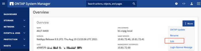
9. Add additional cluster configuration details and click Save to make the changes persistent:
a. Cluster location
b. DNS domain name
c. DNS server IP addresses
![]() DNS server IP addresses can be added individually or with a comma separated list on a single line.
DNS server IP addresses can be added individually or with a comma separated list on a single line.
10. Click Save to make the changes persistent.
11. Select the Settings menu under the Cluster menu.
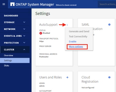
12. If AutoSupport was not configured during the initial setup, click the ellipsis in the AutoSupport tile and select More options.
13. To enable AutoSupport click the slider.
14. Click Edit to change the transport protocol, add a proxy server address and a mail host as needed.
15. Click Save to enable the changes.
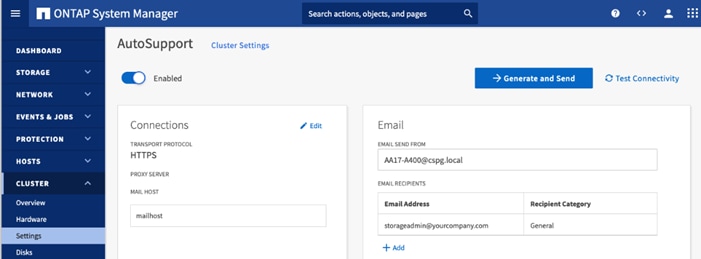
16. In the Email tile to the right, click Edit and enter the desired email information:
a. Email send from address
b. Email recipient addresses.
c. Recipient Category.
17. Click Save when complete.
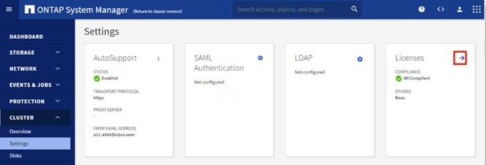
18. Select CLUSTER > Settings at the top left of the page to return to the cluster settings page.
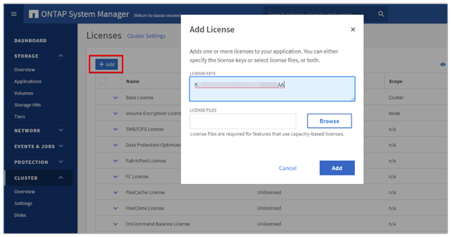
19. Locate the Licenses tile on the right and click the detail arrow.
20. Add the desired licenses to the cluster by clicking Add and entering the license keys in a comma separated list.
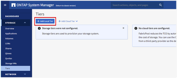
21. Configure storage aggregates by selecting the Storage menu on the left and selecting Tiers.
22. Click Add Local Tier and allow ONTAP System Manager to recommend a storage aggregate configuration.
23. ONTAP will use best practices to recommend an aggregate layout. Click the Recommended details link to view the aggregate information.
24. Optionally, enable NetApp Aggregate Encryption (NAE) by checking the box for Configure Onboard Key Manager for encryption.
25. Enter and confirm the passphrase and save it in a secure location for future use.
26. Click Save to make the configuration persistent.
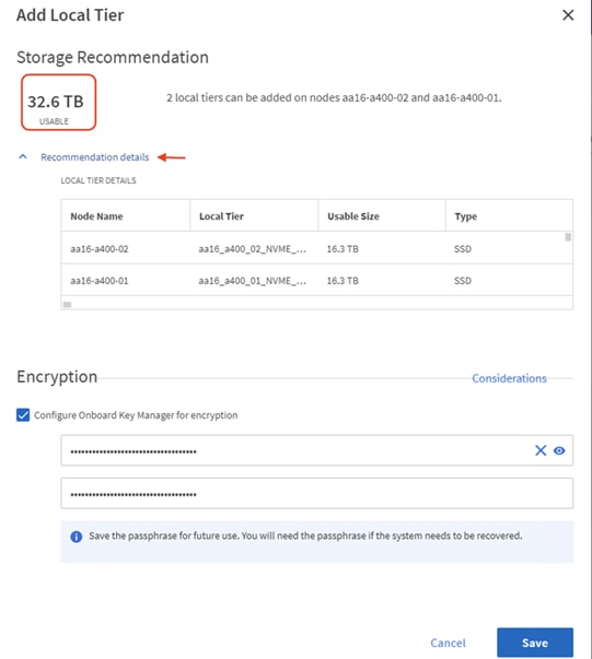
![]() Aggregate encryption may not be supported for all deployments. Please review the NetApp Encryption Power Guide and the Security Hardening Guide for NetApp ONTAP 9 (TR-4569) to help determine if aggregate encryption is right for your environment.
Aggregate encryption may not be supported for all deployments. Please review the NetApp Encryption Power Guide and the Security Hardening Guide for NetApp ONTAP 9 (TR-4569) to help determine if aggregate encryption is right for your environment.
To log into the cluster, follow these steps:
1. Open an SSH connection to either the cluster IP or the host name.
2. Log into the admin user with the password you provided earlier.
To confirm that storage failover is enabled, run the following commands for a failover pair:
1. Verify the status of the storage failover.
AA17-A400::> storage failover show
Takeover
Node Partner Possible State Description
-------------- -------------- -------- -------------------------------------
AA17-A400-01 AA17-A400-02 true Connected to AA17-A400-02
AA17-A400-02 AA17-A400-01 true Connected to AA17-A400-01
2 entries were displayed.
![]() Both <st-node01> and <st-node02> must be capable of performing a takeover. Continue with step 2 if the nodes can perform a takeover.
Both <st-node01> and <st-node02> must be capable of performing a takeover. Continue with step 2 if the nodes can perform a takeover.
2. Enable failover on one of the two nodes if it was not completed during the installation.
storage failover modify -node <st-node01> -enabled true
![]() Enabling failover on one node enables it for both nodes.
Enabling failover on one node enables it for both nodes.
3. Verify the HA status for a two-node cluster.
![]() This step is not applicable for clusters with more than two nodes.
This step is not applicable for clusters with more than two nodes.
AA17-A400::> cluster ha show
High-Availability Configured: true
4. If HA is not configured use the below commands. Only enable HA mode for two-node clusters. Do not run this command for clusters with more than two nodes because it causes problems with failover.
cluster ha modify -configured true
Do you want to continue? {y|n}: y
5. Verify that hardware assist is correctly configured.
AA17-A400::> storage failover hwassist show
Node
-----------------
AA17-A400-01
Partner: AA17-A400-02
Hwassist Enabled: true
Hwassist IP: 192.x.x.84
Hwassist Port: 162
Monitor Status: active
Inactive Reason: -
Corrective Action: -
Keep-Alive Status: healthy
AA17-A400-02
Partner: AA17-A400-01
Hwassist Enabled: true
Hwassist IP: 192.x.x.85
Hwassist Port: 162
Monitor Status: active
Inactive Reason: -
Corrective Action: -
Keep-Alive Status: healthy
2 entries were displayed.
6. If hwassist storage failover is not enabled, enable using the following commands.
storage failover modify –hwassist-partner-ip <node02-mgmt-ip> -node <st-node01>
storage failover modify –hwassist-partner-ip <node01-mgmt-ip> -node <st-node02>
Set Auto-Revert on Cluster Management
To set the auto-revert parameter on the cluster management interface, follow this step:
![]() A storage virtual machine (SVM) is referred to as a Vserver or vserver in the GUI and CLI.
A storage virtual machine (SVM) is referred to as a Vserver or vserver in the GUI and CLI.
1. Run the following command:
net interface modify -vserver <clustername> -lif cluster_mgmt_lif_1 -auto-revert true
To zero all spare disks in the cluster, run the following command:
disk zerospares
![]() Advanced Data Partitioning creates a root partition and two data partitions on each SSD drive in an AFF configuration. Disk autoassign should have assigned one data partition to each node in an HA pair. If a different disk assignment is required, disk autoassignment must be disabled on both nodes in the HA pair by running the disk option modify command. Spare partitions can then be moved from one node to another by running the disk removeowner and disk assign commands.
Advanced Data Partitioning creates a root partition and two data partitions on each SSD drive in an AFF configuration. Disk autoassign should have assigned one data partition to each node in an HA pair. If a different disk assignment is required, disk autoassignment must be disabled on both nodes in the HA pair by running the disk option modify command. Spare partitions can then be moved from one node to another by running the disk removeowner and disk assign commands.
Set Up Service Processor Network Interface
To assign a static IPv4 address to the Service Processor on each node, run the following commands:
system service-processor network modify –node <st-node01> -address-family IPv4 –enable true –dhcp none –ip-address <node01-sp-ip> -netmask <node01-sp-mask> -gateway <node01-sp-gateway>
system service-processor network modify –node <st-node02> -address-family IPv4 –enable true –dhcp none –ip-address <node02-sp-ip> -netmask <node02-sp-mask> -gateway <node02-sp-gateway>
![]() The Service Processor IP addresses should be in the same subnet as the node management IP addresses.
The Service Processor IP addresses should be in the same subnet as the node management IP addresses.
Create Manual Provisioned Aggregates (Optional)
An aggregate containing the root volume is created during the ONTAP setup process. To manually create additional aggregates, determine the aggregate name, the node on which to create it, and the number of disks it should contain.
To create new aggregates, run the following commands:
storage aggregate create -aggregate <aggr1_node01> -node <st-node01> -diskcount <num-disks> -disktype SSD-NVM
storage aggregate create -aggregate <aggr1_node02> -node <st-node02> -diskcount <num-disks> -disktype SSD-NVM
![]() Customer should have the minimum number of hot spare disks for the recommended hot spare disk partitions for their aggregate.
Customer should have the minimum number of hot spare disks for the recommended hot spare disk partitions for their aggregate.
![]() For all-flash aggregates, you should have a minimum of one hot spare disk or disk partition. For non-flash homogenous aggregates, you should have a minimum of two hot spare disks or disk partitions. For Flash Pool aggregates, you should have a minimum of two hot spare disks or disk partitions for each disk type.
For all-flash aggregates, you should have a minimum of one hot spare disk or disk partition. For non-flash homogenous aggregates, you should have a minimum of two hot spare disks or disk partitions. For Flash Pool aggregates, you should have a minimum of two hot spare disks or disk partitions for each disk type.
![]() In an AFF configuration with a small number of SSDs, you might want to create an aggregate with all but one remaining disk (spare) assigned to the controller.
In an AFF configuration with a small number of SSDs, you might want to create an aggregate with all but one remaining disk (spare) assigned to the controller.
![]() The aggregate cannot be created until disk zeroing completes. Run the storage aggregate show command to display the aggregate creation status. Do not proceed until both aggr1_node1 and aggr1_node2 are online.
The aggregate cannot be created until disk zeroing completes. Run the storage aggregate show command to display the aggregate creation status. Do not proceed until both aggr1_node1 and aggr1_node2 are online.
Remove Default Broadcast Domains
By default, all network ports are included in separate default broadcast domain. Network ports used for data services (for example, e0e, e0f, and so on) should be removed from their default broadcast domain and that broadcast domain should be deleted.
To perform this task, run the following commands:
network port broadcast-domain delete -broadcast-domain <Default-N> -ipspace Default
network port broadcast-domain show
Disable Flow Control on 25/100GbE Data Ports
To disable flow control on 25 and 100GbE data ports, follow these steps:
1. Run the following command to configure the ports .on node 01:
network port modify -node <st-node01> -port e3a,e3b -flowcontrol-admin none
network port modify -node <st-node01> -port e0e,e0f,e0g,e0h -flowcontrol-admin none
2. Run the following command to configure the ports on node 02:
network port modify -node <st-node02> -port e3a,e3b -flowcontrol-admin none
network port modify -node <st-node02> -port e0e,e0f,e0g,e0h -flowcontrol-admin none
AA17-A400::> net port show -node * -port e0e,e0f,e0g,e0h -fields speed-admin,duplex-admin,flowcontrol-admin
(network port show)
node port duplex-admin speed-admin flowcontrol-admin
------------ ---- ------------ ----------- -----------------
AA17-A400-01 e0e auto auto none
AA17-A400-01 e0f auto auto none
AA17-A400-01 e0g auto auto none
AA17-A400-01 e0h auto auto none
AA17-A400-02 e0e auto auto none
AA17-A400-02 e0f auto auto none
AA17-A400-02 e0g auto auto none
AA17-A400-02 e0h auto auto none
8 entries were displayed.
AA17-A400::> net port show -node * -port e3a,e3 -fields speed-admin,duplex-admin,flowcontrol-admin (network port show)
node port duplex-admin speed-admin flowcontrol-admin
------------ ---- ------------ ----------- -----------------
AA17-A400-01 e3a auto auto none
AA17-A400-01 e3b auto auto none
AA17-A400-02 e3a auto auto none
AA17-A400-02 e3b auto auto none
4 entries were displayed.
Disable Auto-Negotiate on Fibre Channel Ports (Required only for FC configuration)
In accordance with the best practices for FC host ports, to disable auto-negotiate on each FCP adapter in each controller node, follow these steps:
1. Disable each FC adapter in the controllers with the fcp adapter modify command.
fcp adapter modify -node <st-node01> -adapter 5a –status-admin down
fcp adapter modify -node <st-node01> -adapter 5b –status-admin down
fcp adapter modify -node <st-node02> -adapter 5a –status-admin down
fcp adapter modify -node <st-node02> -adapter 5b –status-admin down
2. Set the desired speed on the adapter and return it to the online state.
fcp adapter modify -node <st-node01> -adapter 5a -speed 32 -status-admin up
fcp adapter modify -node <st-node01> -adapter 5b -speed 32 -status-admin up
fcp adapter modify -node <st-node02> -adapter 5a -speed 32 -status-admin up
fcp adapter modify -node <st-node02> -adapter 5b -speed 32 -status-admin up
Enable Cisco Discovery Protocol
To enable the Cisco Discovery Protocol (CDP) on the NetApp storage controllers, run the following command to enable CDP in ONTAP:
node run -node * options cdpd.enable on
Enable Link-layer Discovery Protocol on all Ethernet Ports
To enable the exchange of Link-layer Discovery Protocol (LLDP) neighbor information between the storage and network switches, follow this step:
Enable LLDP on all ports of all nodes in the cluster.
node run * options lldp.enable on
Create Management Broadcast Domain
If the management interfaces are required to be on a separate VLAN, create a new broadcast domain for those interfaces by running the following command:
network port broadcast-domain create -broadcast-domain IB-MGMT -mtu 1500
To create an NFS data broadcast domain with a maximum transmission unit (MTU) of 9000, run the following commands to create a broadcast domain for NFS in ONTAP:
network port broadcast-domain create -broadcast-domain Infra-NFS -mtu 9000
Create ISCSI Broadcast Domains (Required only for iSCSI configuration)
To create an ISCSI-A and ISCSI-B data broadcast domain with a maximum transmission unit (MTU) of 9000, run the following commands to create a broadcast domain for NFS in ONTAP:
network port broadcast-domain create -broadcast-domain Infra-ISCSI-A -mtu 9000
network port broadcast-domain create -broadcast-domain Infra-ISCSI-B -mtu 9000
Create Interface Groups
To create the LACP interface groups for the 25GbE data interfaces, run the following commands:
network port ifgrp create -node <st-node01> -ifgrp a0a -distr-func port -mode multimode_lacp
network port ifgrp add-port -node <st-node01> -ifgrp a0a -port e0e
network port ifgrp add-port -node <st-node01> -ifgrp a0a -port e0f
network port ifgrp add-port -node <st-node01> -ifgrp a0a -port e0g
network port ifgrp add-port -node <st-node01> -ifgrp a0a -port e0h
network port ifgrp create -node <st-node02> -ifgrp a0a -distr-func port -mode multimode_lacp
network port ifgrp add-port -node <st-node02> -ifgrp a0a -port e0e
network port ifgrp add-port -node <st-node02> -ifgrp a0a -port e0f
network port ifgrp add-port -node <st-node02> -ifgrp a0a -port e0g
network port ifgrp add-port -node <st-node02> -ifgrp a0a -port e0h
To Verify:
AA17-A400::> network port ifgrp show
Port Distribution Active
Node IfGrp Function MAC Address Ports Ports
-------- ---------- ------------ ----------------- ------- -------------------
AA17-A400-01
a0a port d2:39:ea:29:d4:4a full e0e, e0f, e0g, e0h
AA17-A400-02
a0a port d2:39:ea:29:ce:d5 full e0e, e0f, e0g, e0h
2 entries were displayed.
Change MTU on Interface Groups
To change the MTU size on the base interface-group ports before creating the VLAN ports, run the following commands:
network port modify –node <st-node01> -port a0a –mtu 9000
network port modify –node <st-node02> -port a0a –mtu 9000
To create VLANs, follow these steps:
1. Create the management VLAN ports and add them to the management broadcast domain.
network port vlan create –node <st-node01> -vlan-name a0a-<ib-mgmt-vlan-id>
network port vlan create –node <st-node02> -vlan-name a0a-<ib-mgmt-vlan-id>
network port broadcast-domain add-ports -broadcast-domain IB-MGMT -ports <st-node01>:a0a-<ib-mgmt-vlan-id>,<st-node02>:a0a-<ib-mgmt-vlan-id>
To verify, issue the following command:
AA17-A400::> network port vlan show
Network Network
Node VLAN Name Port VLAN ID MAC Address
------ --------- ------- -------- -----------------
AA17-A400-01
a0a-17 a0a 17 d2:39:ea:29:d4:4a
a0a-3017
a0a 3017 d2:39:ea:29:d4:4a
a0a-3117
a0a 3117 d2:39:ea:29:d4:4a
a0a-3217
a0a 3217 d2:39:ea:29:d4:4a
AA17-A400-02
a0a-17 a0a 17 d2:39:ea:29:ce:d5
a0a-3017
a0a 3017 d2:39:ea:29:ce:d5
a0a-3117
a0a 3117 d2:39:ea:29:ce:d5
a0a-3217
a0a 3217 d2:39:ea:29:ce:d5
8 entries were displayed.
2. Create the NFS VLAN ports and add them to the Infra-NFS broadcast domain.
network port vlan create –node <st-node01> -vlan-name a0a-<infra-nfs-vlan-id>
network port vlan create –node <st-node02> -vlan-name a0a-<infra-nfs-vlan-id>
network port broadcast-domain add-ports -broadcast-domain Infra-NFS -ports <st-node01>:a0a-<infra-nfs-vlan-id>,<st-node02>:a0a-<infra-nfs-vlan-id>
3. If configuring iSCSI, create VLAN ports for the iSCSI LIFs on each storage controller and add them to the broadcast domain:
network port vlan create -node <st-node01> -vlan-name a0a-<infra-iscsi-a-vlan-id>
network port vlan create -node <st-node01> -vlan-name a0a-<infra-iscsi-b-vlan-id>
network port vlan create -node <st-node02> -vlan-name a0a-<infra-iscsi-a-vlan-id>
network port vlan create -node <st-node02> -vlan-name a0a-<infra-iscsi-b-vlan-id>
network port broadcast-domain add-ports -broadcast-domain Infra-iSCSI-A -ports <st-node01>:a0a-<infra-iscsi-a-vlan-id>
network port broadcast-domain add-ports -broadcast-domain Infra-iSCSI-B -ports <st-node01>:a0a-<infra-iscsi-b-vlan-id>
network port broadcast-domain add-ports -broadcast-domain Infra-iSCSI-A -ports <st-node02>:a0a-<infra-iscsi-a-vlan-id>
network port broadcast-domain add-ports -broadcast-domain Infra-iSCSI-B -ports <st-node02>:a0a-<infra-iscsi-b-vlan-id>
Configure Timezone
To configure time synchronization on the cluster, follow these steps:
1. Set the time zone for the cluster.
timezone -timezone <timezone>
![]() For example, in the eastern United States, the time zone is America/New_York.
For example, in the eastern United States, the time zone is America/New_York.
Configure Simple Network Management Protocol
To configure the Simple Network Management Protocol (SNMP), follow these steps:
1. Configure basic SNMP information, such as the location and contact. When polled, this information is visible as the sysLocation and sysContact variables in SNMP.
snmp contact <snmp-contact>
snmp location “<snmp-location>”
snmp init 1
options snmp.enable on
2. Configure SNMP traps to send to remote hosts, such as an Active IQ Unified Manager server or another fault management system.
snmp traphost add <oncommand-um-server-fqdn>
SNMPv3 offers advanced security by using encryption and passphrases. The SNMPv3 user can run SNMP utilities from the traphost using the authentication and privacy settings that you specify. To configure SNMPv3 access, run the following commands:
security login create -user-or-group-name <<snmp-v3-usr>> -application snmp -authentication-method usm
Enter the authoritative entity's EngineID [local EngineID]:
Which authentication protocol do you want to choose (none, md5, sha, sha2-256) [none]: <<snmp-v3-auth-proto>>
Enter the authentication protocol password (minimum 8 characters long):
Enter the authentication protocol password again:
Which privacy protocol do you want to choose (none, des, aes128) [none]: <<snmpv3-priv-proto>>
Enter privacy protocol password (minimum 8 characters long):
Enter privacy protocol password again:
![]() Refer to the SNMP Configuration Express Guide for additional information when configuring SNMPv3 security users.
Refer to the SNMP Configuration Express Guide for additional information when configuring SNMPv3 security users.
Create SVM
To create an infrastructure SVM, follow these steps:
1. Run the vserver create command.
vserver create –vserver Infra-SVM –rootvolume infra_svm_root –aggregate aggr1_node01 –rootvolume-security-style unix
2. Remove the unused data protocols from the SVM:
vserver remove-protocols –vserver Infra-SVM -protocols cifs
![]() It is recommended to remove iSCSI or FCP protocols if the protocol is not in use.
It is recommended to remove iSCSI or FCP protocols if the protocol is not in use.
3. Add the two data aggregates to the Infra-SVM aggregate list for the NetApp ONTAP Tools.
vserver modify –vserver Infra-SVM –aggr-list <aggr1_node01>,<aggr1_node02>
4. Enable and run the NFS protocol in the Infra-SVM.
vserver nfs create -vserver Infra-SVM -udp disabled -v3 enabled -v4.1 enabled -vstorage enabled
![]() If the NFS license was not installed during the cluster configuration, make sure to install the license before starting the NFS service.
If the NFS license was not installed during the cluster configuration, make sure to install the license before starting the NFS service.
5. Verify the NFS vstorage parameter for the NetApp NFS VAAI plug-in was enabled.
AA17-A400::> vserver nfs show -fields vstorage
vserver vstorage
--------- --------
Infra-SVM enabled
Create Load-Sharing Mirrors of SVM Root Volume
To create a load-sharing mirror of an SVM root volume, follow these steps:
1. Create a volume to be the load-sharing mirror of the infrastructure SVM root volume on each node.
volume create –vserver Infra-SVM –volume infra_svm_root_m01 –aggregate <aggr1_node01> –size 1GB –type DP
volume create –vserver Infra-SVM –volume infra_svm_root_m02 –aggregate <aggr1_node02> –size 1GB –type DP
2. Create a job schedule to update the root volume mirror relationships every 15 minutes.
job schedule interval create -name 15min -minutes 15
3. Create the mirroring relationships.
snapmirror create –source-path Infra-SVM:infra_svm_root -destination-path Infra-SVM:infra_svm_root_m01 –type LS -schedule 15min
snapmirror create –source-path Infra-SVM:infra_svm_root –destination-path Infra-SVM:infra_svm_root_m02 –type LS -schedule 15min
4. Initialize the mirroring relationship.
snapmirror initialize-ls-set –source-path Infra-SVM:infra_svm_root
To verify:
AA17-A400::> snapmirror show -type ls
Progress
Source Destination Mirror Relationship Total Last
Path Type Path State Status Progress Healthy Updated
----------- ---- ------------ ------- -------------- --------- ------- --------
AA17-A400://Infra-SVM/Infra_SVM_root
LS AA17-A400://Infra-SVM/infra_svm_root_m01
Snapmirrored
Idle - true -
AA17-A400://Infra-SVM/infra_svm_root_m02
Snapmirrored
Idle - true -
2 entries were displayed.
Create FC Block Protocol Service (required only for FC configuration)
Run the following command to create the FCP service. This command also starts the FCP service and sets the worldwide name (WWN) for the SVM:
vserver fcp create -vserver Infra-SVM -status-admin up
To verify:
AA17-A400::> vserver fcp show
Status
Vserver Target Name Admin
---------- ---------------------------- ------
Infra-SVM 20:00:d0:39:ea:29:ce:d4 up
![]() If the FC license was not installed during the cluster configuration, make sure to install the license before creating the FC service.
If the FC license was not installed during the cluster configuration, make sure to install the license before creating the FC service.
Create iSCSI Block Protocol Service (required only for iSCSI configuration)
Run the following command to create the iSCSI service:
vserver iscsi create -vserver <infra-data-svm>
To verify:
AA17-A400::> vserver iscsi show
Target Target Status
Vserver Name Alias Admin
---------- -------------------------------- ---------------------------- ------
Infra-SVM iqn.1992-08.com.netapp:sn.63144a05ad1211eb8a7ad039ea29d44a:vs.3
Infra-SVM up
![]() If the iSCSI license was not installed during the cluster configuration, make sure to install the license before creating the iSCSI service.
If the iSCSI license was not installed during the cluster configuration, make sure to install the license before creating the iSCSI service.
Vserver Protocol Verification
Verify the protocols are added to the Infra vserver
AA17-A400::> vserver show-protocols -vserver Infra-SVM
Vserver: Infra-SVM
Protocols: nfs, fcp, iscsi, ndmp, nvme
If a protocol is not present, use the following command to add the protocol to the vserver:
vserver add-protocols -vserver <infra-data-svm> -protocols < isci or fcp >
Configure HTTPS Access
To configure secure access to the storage controller, follow these steps:
1. Increase the privilege level to access the certificate commands.
set -privilege diag
Do you want to continue? {y|n}: y
2. Generally, a self-signed certificate is already in place. Verify the certificate and obtain parameters (for example, the <serial-number>) by running the following command:
security certificate show
3. For each SVM shown, the certificate common name should match the DNS fully qualified domain name (FQDN) of the SVM. Delete the two default certificates and replace them with either self-signed certificates or certificates from a certificate authority (CA). To delete the default certificates, run the following commands:
security certificate delete -vserver Infra-SVM -common-name Infra-SVM -ca Infra-SVM -type server -serial <serial-number>
![]() Deleting expired certificates before creating new certificates is a best practice. Run the security certificate delete command to delete the expired certificates. In the following command, use TAB completion to select and delete each default certificate.
Deleting expired certificates before creating new certificates is a best practice. Run the security certificate delete command to delete the expired certificates. In the following command, use TAB completion to select and delete each default certificate.
4. To generate and install self-signed certificates, run the following commands as one-time commands. Generate a server certificate for the Infra-SVM and the cluster SVM. Use TAB completion to aid in the completion of these commands.
security certificate create -common-name <cert-common-name> -type server -size 2048 -country <cert-country> -state <cert-state> -locality <cert-locality> -organization <cert-org> -unit <cert-unit> -email-addr <cert-email> -expire-days <cert-days> -protocol SSL -hash-function SHA256 -vserver Infra-SVM
5. To obtain the values for the parameters required in step 5 (<cert-ca> and <cert-serial>), run the security certificate show command.
6. Enable each certificate that was just created by using the –server-enabled true and –client-enabled false parameters. Use TAB completion to aid in the completion of these commands.
security ssl modify -vserver <clustername> -server-enabled true -client-enabled false -ca <cert-ca> -serial <cert-serial> -common-name <cert-common-name>
7. Disable HTTP cluster management access.
system services firewall policy delete -policy mgmt -service http –vserver <clustername>
![]() It is normal for some of these commands to return an error message stating that the entry does not exist.
It is normal for some of these commands to return an error message stating that the entry does not exist.
8. Change back to the normal admin privilege level and verify that the system logs are available in a web browser.
set –privilege admin
https://<node01-mgmt-ip>/spi
https://<node02-mgmt-ip>/spi
Configure NFSv3 and NFSv4.1
To configure NFS on the SVM, follow these steps:
1. Create a new rule for the infrastructure NFS subnet in the default export policy.
vserver export-policy rule create –vserver Infra-SVM -policyname default –ruleindex 1 –protocol nfs -clientmatch <infra-nfs-subnet-cidr> -rorule sys –rwrule sys -superuser sys –allow-suid true
2. Assign the FlexPod export policy to the infrastructure SVM root volume.
volume modify –vserver Infra-SVM –volume infra_svm_root –policy default
The following information is required to create a NetApp FlexVol® volume:
● The volume name
● The volume size
● The aggregate on which the volume exists
To create a FlexVol volume, run the following commands:
volume create -vserver Infra-SVM -volume infra_datastore_1 -aggregate <aggr1_node01> -size 1TB -state online -policy default -junction-path /infra_datastore_01 -space-guarantee none -percent-snapshot-space 0
volume create -vserver Infra-SVM -volume infra_datastore_2 -aggregate <aggr1_node02> -size 1TB -state online -policy default -junction-path /infra_datastore_02 -space-guarantee none -percent-snapshot-space 0
volume create -vserver Infra-SVM -volume infra_swap -aggregate <aggr1_node01> -size 100GB -state online -policy default -junction-path /infra_swap -space-guarantee none -percent-snapshot-space 0 -snapshot-policy none.
volume create -vserver Infra-SVM -volume esxi_boot -aggregate <aggr1_node01> -size 320GB -state online -policy default -space-guarantee none -percent-snapshot-space 0
snapmirror update-ls-set -source-path Infra-SVM:infra_svm_root
![]() If you are going to setup and use SnapCenter to backup the infra_datastore volume, add “-snapshot-policy none” to the end of the volume create command for the infra_datastore volume.
If you are going to setup and use SnapCenter to backup the infra_datastore volume, add “-snapshot-policy none” to the end of the volume create command for the infra_datastore volume.
On NetApp AFF systems, deduplication is enabled by default. To disable the efficiency policy on the infra_swap volume, run the following command:
volume efficiency off –vserver Infra-SVM –volume infra_swap
To create NFS LIFs, run the following commands:
network interface create -vserver Infra-SVM -lif nfs-lif-01 -role data -data-protocol nfs -home-node <st-node01> -home-port a0a-<infra-nfs-vlan-id> –address <node01-nfs-lif-01-ip> -netmask <node01-nfs-lif-01-mask> -status-admin up –failover-policy broadcast-domain-wide –firewall-policy data –auto-revert true
network interface create -vserver Infra-SVM -lif nfs-lif-02 -role data -data-protocol nfs -home-node <st-node02> -home-port a0a-<infra-nfs-vlan-id> –address <node02-nfs-lif-02-ip> -netmask <node02-nfs-lif-02-mask>> -status-admin up –failover-policy broadcast-domain-wide –firewall-policy data –auto-revert true
To verify:
AA17-A400::> network interface show -vserver Infra-SVM -data-protocol nfs
Logical Status Network Current Current Is
Vserver Interface Admin/Oper Address/Mask Node Port Home
----------- ---------- ---------- ------------------ ------------- ------- ----
Infra-SVM
nfs-lif-01 up/up 192.168.30.1/24 AA17-A400-01 a0a-3017
true
nfs-lif-02 up/up 192.168.30.2/24 AA17-A400-02 a0a-3017
true
2 entries were displayed.
Create FC LIFs (required only for FC configuration)
Run the following commands to create four FC LIFs (two on each node):
network interface create -vserver Infra-SVM -lif fcp-lif-01a -role data -data-protocol fcp -home-node <st-node01> -home-port 5a –status-admin up
network interface create -vserver Infra-SVM -lif fcp-lif-01b -role data -data-protocol fcp -home-node <st-node01> -home-port 5b –status-admin up
network interface create -vserver Infra-SVM -lif fcp-lif-02a -role data -data-protocol fcp -home-node <st-node02> -home-port 5a –status-admin up
network interface create -vserver Infra-SVM -lif fcp-lif-02b -role data -data-protocol fcp -home-node <st-node02> -home-port 5b –status-admin up
To verify:
To verify:
AA17-A400::> network interface show -vserver Infra-SVM -data-protocol fcp
Logical Status Network Current Current Is
Vserver Interface Admin/Oper Address/Mask Node Port Home
----------- ---------- ---------- ------------------ ------------- ------- ----
Infra-SVM
fcp-lif-01a up/up 20:01:d0:39:ea:29:ce:d4
AA17-A400-01 5a true
fcp-lif-01b up/up 20:02:d0:39:ea:29:ce:d4
AA17-A400-01 5b true
fcp-lif-02a up/up 20:03:d0:39:ea:29:ce:d4
AA17-A400-02 5a true
fcp-lif-02b up/up 20:04:d0:39:ea:29:ce:d4
AA17-A400-02 5b true
4 entries were displayed.
Create iSCSI LIFs (required only for iSCSI configuration)
To create four iSCSI LIFs, run the following commands (two on each node):
network interface create -vserver <infra-data-svm> -lif iscsi-lif-01a -role data -data-protocol iscsi -home-node <st-node01> -home-port a0a-<infra-iscsi-a-vlan-id> -address <st-node01-infra-iscsi-a–ip> -netmask <infra-iscsi-a-mask> -status-admin up
network interface create -vserver <infra-data-svm> -lif iscsi-lif-01b -role data -data-protocol iscsi -home-node <st-node01> -home-port a0a-<infra-iscsi-b-vlan-id> -address <st-node01-infra-iscsi-b–ip> -netmask <infra-iscsi-b-mask> –status-admin up
network interface create -vserver <infra-data-svm> -lif iscsi-lif-02a -role data -data-protocol iscsi -home-node <st-node02> -home-port a0a-<infra-iscsi-a-vlan-id> -address <st-node02-infra-iscsi-a–ip> -netmask <infra-iscsi-a-mask> –status-admin up
network interface create -vserver <infra-data-svm> -lif iscsi-lif-02b -role data -data-protocol iscsi -home-node <st-node02> -home-port a0a-<infra-iscsi-b-vlan-id> -address <st-node02-infra-iscsi-b–ip> -netmask <infra-iscsi-b-mask> –status-admin up
To verify:
AA17-A400::> network interface show -vserver Infra-SVM -data-protocol iscsi
Logical Status Network Current Current Is
Vserver Interface Admin/Oper Address/Mask Node Port Home
----------- ---------- ---------- ------------------ ------------- ------- ----
Infra-SVM
iscsi-lif-01a
up/up 192.168.31.1/24 AA17-A400-01 a0a-3117
true
iscsi-lif-01b
up/up 192.168.32.1/24 AA17-A400-01 a0a-3217
true
iscsi-lif-02a
up/up 192.168.31.2/24 AA17-A400-02 a0a-3117
true
iscsi-lif-02b
up/up 192.168.32.2/24 AA17-A400-02 a0a-3217
true
4 entries were displayed.
Configure FC-NVMe Datastore for vSphere 7U2 (for FC-NVMe configuration only)
To Configure FC-NVMe Datastores for vSphere 7U2 enable the FC-NVMe protocol on an existing SVM or create a separate SVM for FC-NVMe workloads. In this deployment, Infra-SVM was used for FC-NVMe datastore configuration.
To configure FC-NVMe datastore on existing SVM (Infra-SVM) follow these steps:
1. Verify NVMe Capable adapters are installed in the cluster.
network fcp adapter show -data-protocols-supported fc-nvme
2. Add the NVMe protocol to the SVM and list it.
vserver add-protocols -vserver Infra-SVM -protocols nvme
To verify:
AA17-A400::> vserver show -vserver Infra-SVM -fields allowed-protocols
vserver allowed-protocols
--------- -----------------------
Infra-SVM nfs,fcp,iscsi,ndmp,nvme
3. Create NVMe service.
vserver nvme create -vserver Infra-SVM
To verify:
AA17-A400::> vserver nvme show -vserver Infra-SVM
Vserver Name: Infra-SVM
Administrative Status: up
4. Create NVMe FC LIFs.
network interface create -vserver Infra-SVM -lif fc-nvme-lif-01a -role data -data-protocol fc-nvme -home-node <st-node01> -home-port 5a –status-admin up
network interface create -vserver Infra-SVM -lif fc-nvme-lif-01b -role data -data-protocol fc-nvme -home-node <st-node01> -home-port 5b –status-admin up
network interface create -vserver Infra-SVM -lif fcp-nvme-lif-02a -role data -data-protocol fc-nvme -home-node <st-node02> -home-port 5a –status-admin up
network interface create -vserver Infra-SVM -lif fcp-nvme-lif-02b -role data -data-protocol fc-nvme -home-node <st-node02> -home-port 5b –status-admin up
To verify:
AA17-A400::> network interface show -vserver Infra-SVM -data-protocol fc-nvme
Logical Status Network Current Current Is
Vserver Interface Admin/Oper Address/Mask Node Port Home
----------- ---------- ---------- ------------------ ------------- ------- ----
Infra-SVM
fc-nvme-lif-01a
up/up 20:06:d0:39:ea:29:ce:d4
AA17-A400-01 5b true
fc-nvme-lif-01b
up/up 20:08:d0:39:ea:29:ce:d4
AA17-A400-01 5a true
fc-nvme-lif-02a
up/up 20:07:d0:39:ea:29:ce:d4
AA17-A400-02 5b true
fc-nvme-lif-02b
up/up 20:09:d0:39:ea:29:ce:d4
AA17-A400-02 5a true
![]() You can only configure two NVMe LIFs per node on a maximum of four nodes.
You can only configure two NVMe LIFs per node on a maximum of four nodes.
5. Create Volume.
vol create -vserver Infra-SVM -volume NVMe_Datastore_01 -aggregate AA17_A400_01_NVME_SSD_1 -size 500G -state online -space-guarantee none -percent-snapshot-space 0
Add Infrastructure SVM Administrator
To add the infrastructure SVM administrator and SVM administration LIF in the in-band management network, follow these steps:
1. Run the following commands:
network interface create –vserver Infra-SVM –lif svm-mgmt –role data –data-protocol none –home-node <st-node02> -home-port a0a-<ib-mgmt-vlan-id> –address <svm-mgmt-ip> -netmask <svm-mgmt-mask> -status-admin up –failover-policy broadcast-domain-wide –firewall-policy mgmt –auto-revert true
2. Create a default route that enables the SVM management interface to reach the outside world.
network route create –vserver Infra-SVM -destination 0.0.0.0/0 –gateway <svm-mgmt-gateway>
To verify:
AA17-A400::> network route show -vserver Infra-SVM
Vserver Destination Gateway Metric
------------------- --------------- --------------- ------
Infra-SVM
0.0.0.0/0 192.168.17.254 20
3. Set a password for the SVM vsadmin user and unlock the user.
security login password –username vsadmin –vserver Infra-SVM
Enter a new password: <password>
Enter it again: <password>
security login unlock –username vsadmin –vserver Infra-SVM
![]() A cluster serves data through at least one and possibly several SVMs. These steps have created a single data SVM. Customers can create additional SVMs depending on their requirement.
A cluster serves data through at least one and possibly several SVMs. These steps have created a single data SVM. Customers can create additional SVMs depending on their requirement.
Configure AutoSupport
NetApp AutoSupport® sends support summary information to NetApp through HTTPS. To configure AutoSupport, run the following command:
system node autosupport modify -node * -state enable –mail-hosts <mailhost> -transport https -support enable -noteto <storage-admin-email>
Cisco Intersight Managed Mode Configuration
The Cisco Intersight™ platform is a management solution delivered as a service with embedded analytics for Cisco® and third-party IT infrastructures. The Cisco Intersight managed mode (also referred to as Cisco IMM or Intersight managed mode) is a new architecture that manages Cisco Unified Computing System™ (Cisco UCS®) fabric interconnect–attached systems through a Redfish-based standard model. Cisco Intersight managed mode standardizes both policy and operation management for Cisco UCS B200 M6 and Cisco UCSX X210c M6 compute nodes used in this deployment guide.
![]() Cisco UCS C-Series M6 servers, connected and managed through UCS FIs, are also supported by IMM. For a complete list of supported platforms, visit: https://www.cisco.com/c/en/us/td/docs/unified_computing/Intersight/b_Intersight_Managed_Mode_Configuration_Guide/b_intersight_managed_mode_guide_chapter_01010.html
Cisco UCS C-Series M6 servers, connected and managed through UCS FIs, are also supported by IMM. For a complete list of supported platforms, visit: https://www.cisco.com/c/en/us/td/docs/unified_computing/Intersight/b_Intersight_Managed_Mode_Configuration_Guide/b_intersight_managed_mode_guide_chapter_01010.html
Set up Cisco Intersight Managed Mode on Cisco UCS Fabric Interconnects
The Cisco UCS fabric interconnects need to be set up to support Cisco Intersight managed mode. When converting an existing pair of Cisco UCS fabric interconnects from Cisco UCS Manager mode to Intersight Mange Mode (IMM), first erase the configuration and reboot your system.
![]() Converting fabric interconnects to Cisco Intersight managed mode is a disruptive process, and configuration information will be lost. Customers are encouraged to make a backup of their existing configuration. If a software version that supports Intersight Managed Mode (4.1(3) or later) is already installed on Cisco UCS Fabric Interconnects, do not upgrade the software to a recommended recent release using Cisco UCS Manager. The software upgrade will be performed using Cisco Intersight to make sure Cisco UCS X-series firmware is part of the software upgrade.
Converting fabric interconnects to Cisco Intersight managed mode is a disruptive process, and configuration information will be lost. Customers are encouraged to make a backup of their existing configuration. If a software version that supports Intersight Managed Mode (4.1(3) or later) is already installed on Cisco UCS Fabric Interconnects, do not upgrade the software to a recommended recent release using Cisco UCS Manager. The software upgrade will be performed using Cisco Intersight to make sure Cisco UCS X-series firmware is part of the software upgrade.
1. Configure Fabric Interconnect A (FI-A). On the Basic System Configuration Dialog screen, set the management mode to Intersight. All the remaining settings are similar to those for the Cisco UCS Manager managed mode (UCSM-Managed).
Cisco UCS Fabric Interconnect A
To configure the Cisco UCS for use in a FlexPod environment in ucsm managed mode, follow these steps:
1. Connect to the console port on the first Cisco UCS fabric interconnect.
Enter the configuration method. (console/gui) ? console
Enter the management mode. (ucsm/intersight)? intersight
You have chosen to setup a new Fabric interconnect in “intersight” managed mode. Continue? (y/n): y
Enforce strong password? (y/n) [y]: Enter
Enter the password for "admin": <password>
Confirm the password for "admin": <password>
Enter the switch fabric (A/B) []: A
Enter the system name: <ucs-cluster-name>
Physical Switch Mgmt0 IP address : <ucsa-mgmt-ip>
Physical Switch Mgmt0 IPv4 netmask : <ucsa-mgmt-mask>
IPv4 address of the default gateway : <ucsa-mgmt-gateway>
Configure the DNS Server IP address? (yes/no) [n]: y
DNS IP address : <dns-server-1-ip>
Configure the default domain name? (yes/no) [n]: y
Default domain name : <ad-dns-domain-name>
<SNIP>
Verify and save the configuration.
2. After applying the settings, make sure you can ping the fabric interconnect management IP address. When Fabric Interconnect A is correctly set up and is available, Fabric Interconnect B will automatically discover Fabric Interconnect A during its setup process as shown in the next step.
3. Configure Fabric Interconnect B (FI-B). For the configuration method, choose console. Fabric Interconnect B will detect the presence of Fabric Interconnect A and will prompt you to enter the admin password for Fabric Interconnect A. Provide the management IP address for Fabric Interconnect B and apply the configuration.
Cisco UCS Fabric Interconnect A
Enter the configuration method. (console/gui) ? console
Installer has detected the presence of a peer Fabric interconnect. This Fabric interconnect will be added to the cluster. Continue (y/n) ? y
Enter the admin password of the peer Fabric interconnect: <password>
Connecting to peer Fabric interconnect... done
Retrieving config from peer Fabric interconnect... done
Peer Fabric interconnect Mgmt0 IPv4 Address: <ucsa-mgmt-ip>
Peer Fabric interconnect Mgmt0 IPv4 Netmask: <ucsa-mgmt-mask>
Peer FI is IPv4 Cluster enabled. Please Provide Local Fabric Interconnect Mgmt0 IPv4 Address
Physical Switch Mgmt0 IP address : <ucsb-mgmt-ip>
Local fabric interconnect model(UCS-FI-6454)
Peer fabric interconnect is compatible with the local fabric interconnect. Continuing with the installer...
Apply and save the configuration (select 'no' if you want to re-enter)? (yes/no): yes
Set Up Cisco Intersight Account
In this step customers are setting up a new Cisco Intersight account.
1. Go to https://intersight.com and click Create an account.
2. Read and accept the license agreement. Click Next.
3. Provide an Account Name and click Create.
4. On successful creation of the Intersight account, following page will be displayed:
![]() Customers also can choose to add the Cisco UCS FIs to an existing Cisco Intersight account.
Customers also can choose to add the Cisco UCS FIs to an existing Cisco Intersight account.
Set up Cisco Intersight licensing
When setting up a new Cisco Intersight account (as discussed in this document), the account needs to be enabled for Cisco Smart Software Licensing.
Associate the Cisco Intersight account with Cisco Smart Licensing by following these steps:
1. Log in to the Cisco Smart Licensing portal: https://software.cisco.com/software/csws/ws/platform/home?locale=en_US#module/SmartLicensing.
2. Verify that the correct virtual account is selected.
3. Under Inventory > General, generate a new token for product registration.
4. Copy this newly created token.
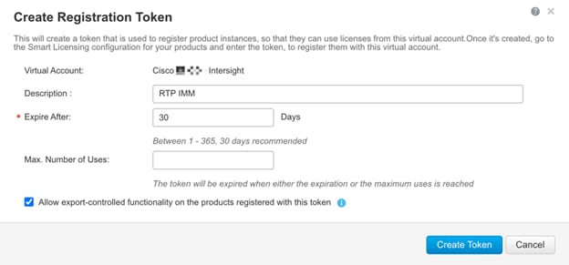
5. Log in to the Cisco Intersight portal and click Settings (the gear icon) in the top-right corner. Select Licensing.
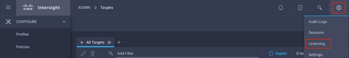
6. Under Cisco Intersight > Licensing, click Register.
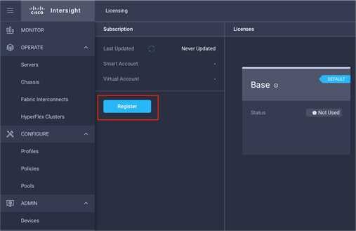
7. Enter the copied token from the Cisco Smart Licensing portal. Click Next.
8. Drop-down the pre-selected Default Tier * and select the license type (for example, Premier).
9. Select Move All Servers to Default Tier.
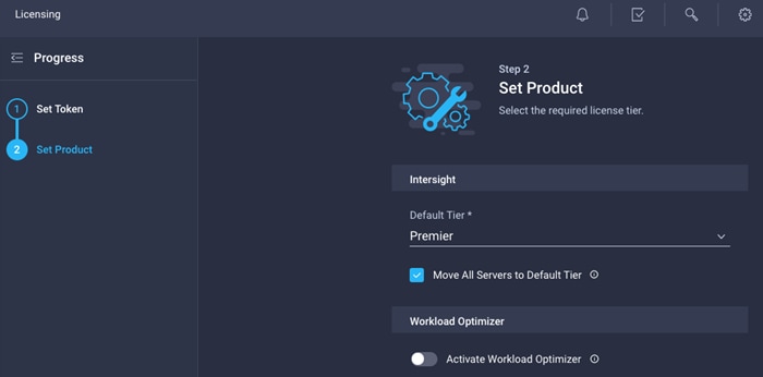
10. Click Register.
11. When the registration is successful (takes a few minutes), the information about the associated Cisco Smart account and default licensing tier selected in the last step is displayed.
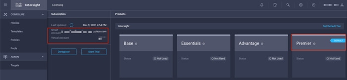
Set Up Cisco Intersight Resource Group
In this step an Intersight resource group is created where resources such as targets will be logically grouped. In this deployment, a single resource group is created to host all the resources, but customers can choose to create multiple resource groups for granular control of the resources.
To define a new resource group, follow these steps:
1. Log in to the Cisco Intersight.
2. Click Settings (the gear icon) and choose Settings.
3. Click Resource Groups in the middle panel.
4. Click + Create Resource Group in the top-right corner.
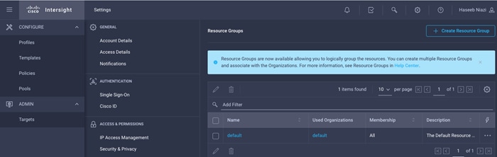
5. Provide a name for the Resource Group (for example, AA17-rg).
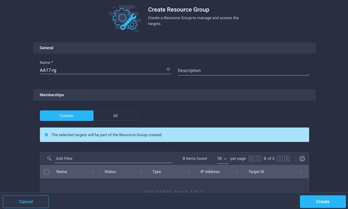
6. Under Memberships, select Custom.
7. Click Create.
Set Up Cisco Intersight Organization
In this step an Intersight organization is created where all Cisco Intersight managed mode configurations including policies are defined. To define a new organization, follow these steps:
1. Log in to the Cisco Intersight portal.
2. Click Settings (the gear icon) and choose Settings.

3. Click Organizations in the middle panel.
4. Click + Create Organization in the top-right corner.

5. Provide a name for the organization (for example, AA17).
6. Select the Resource Group created in the last step (for example, AA17-rg).
7. Click Create.
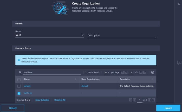
Claim Cisco UCS Fabric Interconnects in Cisco Intersight
Make sure the initial configuration for the fabric interconnects has been completed. Log in to Fabric Interconnect A using a web browser to capture the Cisco Intersight connectivity information. To claim Cisco UCS Fabric Interconnects in Cisco Intersight, follow these steps:
1. Use the management IP address of Fabric Interconnect A to access the device from a web browser and the previously configured admin password to log in to the device.
2. Under DEVICE CONNECTOR, the current device status will show “Not claimed”. Note or copy, the Device ID and Claim Code information for claiming the device in Cisco Intersight.
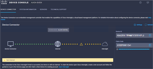
4. Click Targets from the left menu.
5. Click Claim New Target.
6. Select Cisco UCS Domain (Intersight Managed) and click Start.
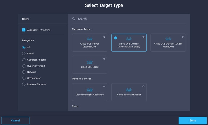
7. Enter the Device ID and Claim Code captured from the Cisco UCS FI.
8. Select the previously created Resource Group and click Claim.
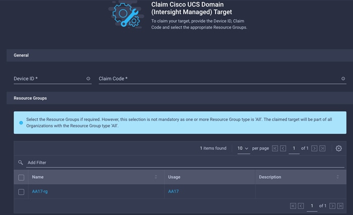
9. On a successful device claim, Cisco UCS FI should appear as a target in Cisco Intersight.
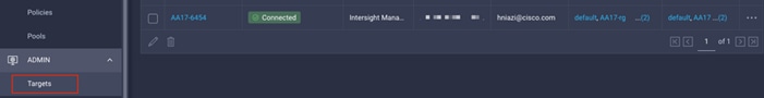
Verify Addition of Cisco UCS Fabric Interconnects to Cisco Intersight
To verify Cisco UCS fabric interconnects are added to Intersight account, follow these steps:
1. Log back to the web GUI of the Cisco UCS fabric interconnect and click the browser refresh button.
2. The fabric interconnect status should now be set to Claimed.
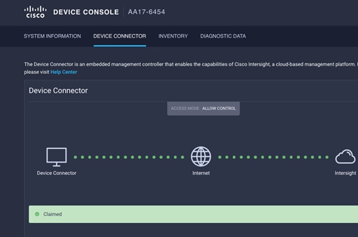
Upgrade Fabric Interconnect Firmware using Cisco Intersight
Cisco UCS Manager does not support Cisco UCS X-Series therefore Fabric Interconnect software upgrade performed using UCS Manager does not contain the firmware for Cisco UCS X-series. Before setting up UCS domain profile and discovering the chassis, upgrade the Fabric Interconnect firmware to the latest recommended release using Cisco Intersight.
![]() If Cisco UCS Fabric Interconnects were upgraded to the latest recommended software using Cisco UCS Manager, this upgrade process through Intersight will still work and will copy the X-Series firmware to the Fabric Interconnects.
If Cisco UCS Fabric Interconnects were upgraded to the latest recommended software using Cisco UCS Manager, this upgrade process through Intersight will still work and will copy the X-Series firmware to the Fabric Interconnects.
To perform the software upgrade, follow these steps:
1. Log in to the Cisco Intersight portal.
2. Click to expand OPERATE in the left pane and select Fabric Interconnects.
3. Click the three dots “…” at the end of the row for either of the Fabric Interconnects and select Upgrade Firmware.
4. Click Start.
5. Verify the Fabric Interconnect information and click Next.
6. Enable Advanced Mode using the toggle switch and uncheck Fabric Interconnect Traffic Evacuation.
7. Select the recommended release from the list and click Next.
8. Verify the information and click Upgrade to start the upgrade process.
9. Keep an eye on the Request panel of the main Intersight screen as the system will ask for user permission before upgrading each FI. Click on the Circle with Arrow and follow the prompts on screen to grant permission.
10. Wait for both the FIs to successfully upgrade.
Configure a Cisco UCS Domain Profile
A Cisco UCS domain profile configures a fabric interconnect pair through reusable policies, allows configuration of the ports and port channels, and configures the VLANs and VSANs in the network. It defines the characteristics of and configured ports on fabric interconnects. The domain-related policies can be attached to the profile either at the time of creation or later. One Cisco UCS domain profile can be assigned to one fabric interconnect domain.
To create a Cisco UCS domain profile, follow these steps:
1. Log in to the Cisco Intersight portal.
2. Click to expand CONFIGURE in the left pane and select Profiles.
3. In the main window, select UCS Domain Profiles and click Create UCS Domain Profile.
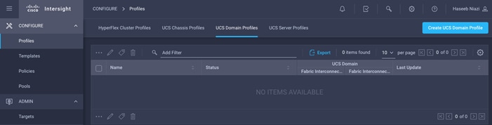
4. On the Create UCS Domain Profile screen, click Start.
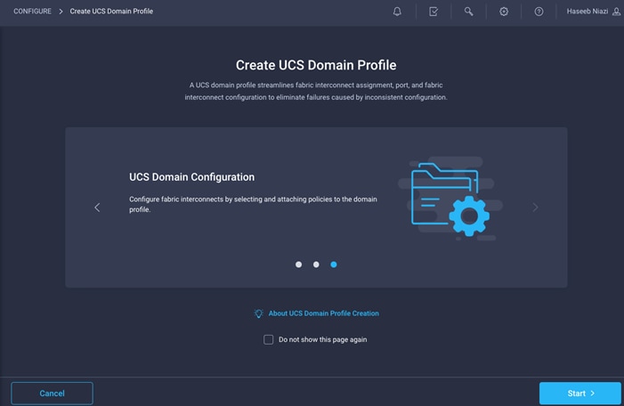
Follow these steps for the general configuration:
1. Select the organization from the drop-down list (for example, AA17).
2. Provide a name for the domain profile (for example, AA17-Domain-Profile).
3. Provide an optional Description.
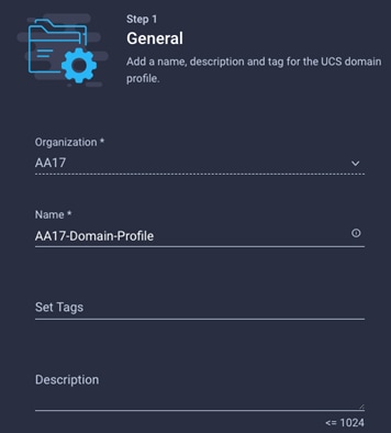
4. Click Next.
Step 2: Cisco UCS Domain Assignment
Follow these steps for Cisco UCS domain assignment:
1. Assign the Cisco UCS domain to this new domain profile by clicking Assign Now and selecting the previously added Cisco UCS domain (for example, AA17-6454).
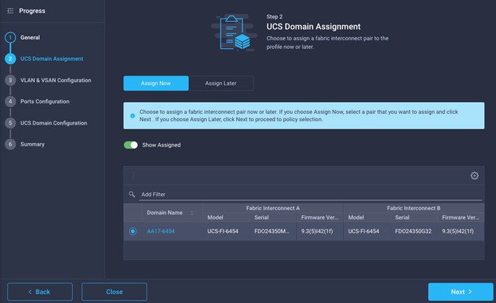
2. Click Next.
Step 3: VLAN and VSAN Configuration
In this step, a single VLAN policy is created for both fabric interconnects and two individual VSAN policies are created because the VSAN IDs are unique for each fabric interconnect.
Create and apply VLAN policy
Follow these steps to create and apply the VLAN policy:
1. Click Select Policy next to VLAN Configuration under Fabric Interconnect A.
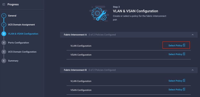
2. In the pane on the right, click Create New.
3. Verify correct organization is selected from the drop-down list (for example, AA17) and provide a name for the policy (for example, AA17-VLAN).
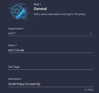
4. Click Next.
5. Click Add VLANs.
6. Provide a name and VLAN ID for the native VLAN.
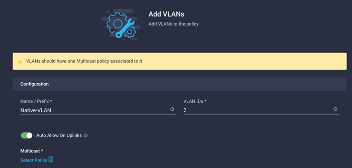
7. Make sure Auto Allow On Uplinks is enabled.
8. To create the required Multicast policy, click Select Policy under Multicast*.
9. In the window on the right, Click Create New to create a new Multicast Policy.
10. Provide a Name for the Multicast Policy (for example, AA17-MCAST-Pol).
11. Provide optional Description and click Next.
12. Leave the Snooping State selected and click Create.
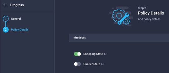
13. Click Add to add the VLAN.
14. Select Set Native VLAN ID and enter the VLAN number (for example, 2) under VLAN ID.
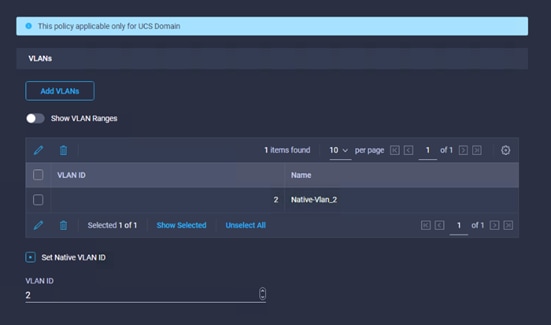
15. Add the remaining VLANs for FlexPod by clicking Add VLANs and entering the VLANs one by one. Reuse the previously created multicast policy for all the VLANs.
16. The VLANs created during this validation are shown in the screen image below.
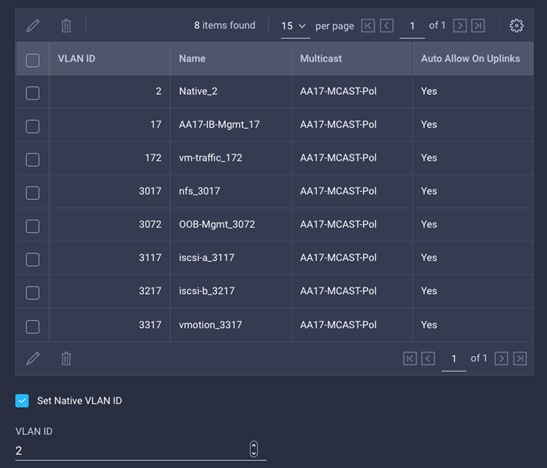
![]() The iSCSI VLANs shown in the screen image above are only needed when iSCSI is configured in the environment.
The iSCSI VLANs shown in the screen image above are only needed when iSCSI is configured in the environment.
17. Click Create at bottom right to finish creating the VLAN policy and associated VLANs.
18. Click Select Policy next to VLAN Configuration for Fabric Interconnect B and select the same VLAN policy.
Create and Apply VSAN Policy (FC configuration only)
Follow these steps to create and apply the VSAN policy. A VSAN policy is only needed when configuring Fibre Channel and can be skipped when configuring IP-only storage access.
1. Click Select Policy next to VSAN Configuration under Fabric Interconnect A. Then, in the pane on the right, click Create New.
2. Verify correct organization is selected from the drop-down list (for example, AA17) and provide a name for the policy (for example, AA17-VSAN-Pol-A).
3. Click Next.
4. Enable Uplink Trunking.

5. Click Add VSAN and provide a name (for example, VSAN-A), VSAN ID (for example, 101), and associated Fibre Channel over Ethernet (FCoE) VLAN ID (for example, 101) for SAN A.
6. Set VLAN Scope as Uplink.
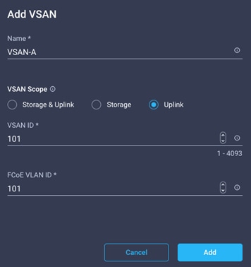
7. Click Add.
8. Click Create to finish creating VSAN policy for fabric A.
9. Repeat the same steps to create a new VSAN policy for SAN-B. Name the policy to identify the SAN-B configuration (for example, AA17-VSAN-Pol-B) and use appropriate VSAN and FCoE VLAN (for example, 102).
10. Verify that a common VLAN policy and two unique VSAN policies are associated with the two fabric interconnects.
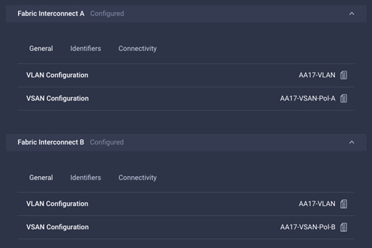
11. Click Next.
Step 3: Ports Configuration
Follow these steps to configure the ports on the fabric interconnects:
1. Click Select Policy for Fabric Interconnect A.
2. Click Create New in the pane on the right to define a new port configuration policy.
![]() Use two separate port policies for the fabric interconnects. Using separate policies provide flexibility when port configuration (port numbers or speed) differs between the two FIs. When configuring Fibre Channel, two port policies are required because each fabric interconnect uses unique Fibre Channel VSAN ID.
Use two separate port policies for the fabric interconnects. Using separate policies provide flexibility when port configuration (port numbers or speed) differs between the two FIs. When configuring Fibre Channel, two port policies are required because each fabric interconnect uses unique Fibre Channel VSAN ID.
3. Verify correct organization is selected from the drop-down list (for example, AA17) and provide a name for the policy (for example, AA17-PortPol-A).
4. Click Next.
5. Move the slider to set up unified ports. In this deployment, the first four ports were selected as Fibre Channel ports. Click Next.
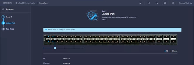
6. Select all the ports that need to be configured as server ports by clicking the ports in the graphics (or select from the list below the graphic). When all ports are selected, click Configure.
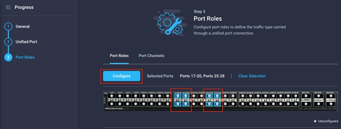
7. From the drop-down list, select Server as the role.
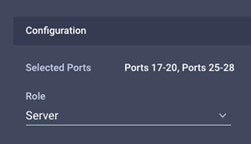
8. Click Save.
9. Configure the Ethernet uplink port channel by selecting the Port Channel in the main pane and then clicking Create Port Channel.
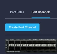
10. Select Ethernet Uplink Port Channel as the role, provide a port-channel ID (for example, 11), and select a value for Admin Speed from drop-down list (for example, Auto).
![]() Customers can create the Ethernet Network Group, Flow Control, Ling Aggregation or Link control policy for defining disjoint Layer-2 domain or fine tune port-channel parameters. These policies were not used in this deployment and system default values were utilized.
Customers can create the Ethernet Network Group, Flow Control, Ling Aggregation or Link control policy for defining disjoint Layer-2 domain or fine tune port-channel parameters. These policies were not used in this deployment and system default values were utilized.
11. Scroll down and select uplink ports from the list of available ports (for example, port 49 and 50)
12. Click Save.
Configure FC Port Channel (FC configuration only)
FC uplink port channel is only needed when configuring FC SAN and can be skipped for IP-only (iSCSI) storage access. To configure FC port-channel, follow these steps:
1. Configure a Fibre Channel Port Channel by selecting the Port Channel in the main pane again and clicking Create Port Channel.
2. In the drop-down list under Role, choose FC Uplink Port Channel.
3. Provide a port-channel ID (for example, 1), select a value for Admin Speed (for example, 32Gbps), and provide a VSAN ID (for example, 101).
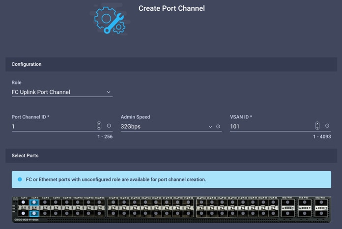
4. Select ports (for example, 3 and 4).
5. Click Save.
6. Verify the port-channel IDs and ports after both the Ethernet uplink port channel and the Fibre Channel uplink port channel have been created.
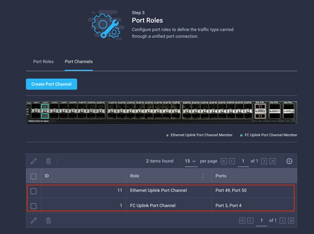
7. Click Save to create the port policy for Fabric Interconnect A.
![]() Use the summary screen to verify that the ports were selected and configured correctly.
Use the summary screen to verify that the ports were selected and configured correctly.
Port Configuration for Fabric Interconnect B
Repeat the steps above to create the port policy for Fabric Interconnect B including the Ethernet port-channel and the FC port-channel (if configuring SAN). Use the following values for various parameters:
● Name of the port policy: AA17-PortPol-B
● Ethernet port-Channel ID: 12
● FC port-channel ID: 2
● FC VSAN ID: 102
When the port configuration for both fabric interconnects is complete and looks good, click Next.
Step 5: UCS Domain Configuration
Under UCS domain configuration, additional policies can be configured to setup NTP, Syslog, DNS settings, SNMP, QoS and UCS operating mode (end host or switch mode). For this deployment, three policies (NTP, Network Connectivity and System QoS) will be configured.
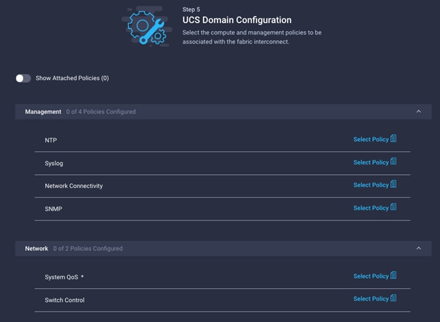
Configure NTP Policy
To define an NTP server for the Cisco UCS domain, follow these steps:
1. Click Select Policy next to NTP and then, in the pane on the right, click Create New.
2. Verify correct organization is selected from the drop-down list (for example, AA17) and provide a name for the policy (for example, AA17-NTPPol).
3. Click Next.
4. Enable NTP, provide the NTP server IP addresses, and select the time zone from the drop-down list.
5. If required, add a second NTP server by clicking + next to the first NTP server IP address.
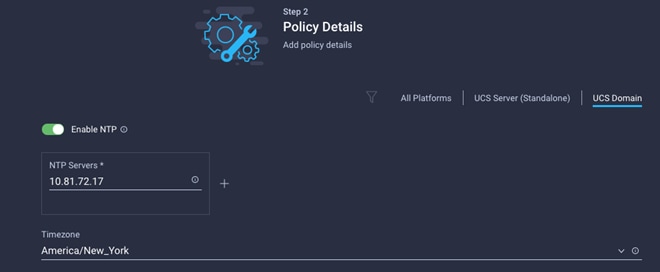
6. Click Create.
Configure Network Connectivity Policy
To define the Doman Name Service (DNS) servers for Cisco UCS, configure network connectivity policy.
1. Click Select Policy next to Network Connectivity and then, in the pane on the right, click Create New.
2. Verify correct organization is selected from the drop-down list (for example, AA17) and provide a name for the policy (for example, AA17-NetConn-Pol).
3. Provide DNS server IP addresses for Cisco UCS (for example, 10.81.72.40 and 10.81.72.41).
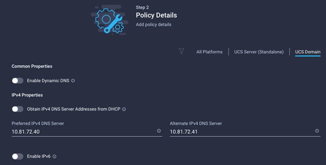
4. Click Create.
Configure System QoS Policy
To define the QoS settings for Cisco UCS, follow these steps:
1. Click Select Policy next to System QoS* and in the pane on the right, click Create New.
2. Verify correct organization is selected from the drop-down list (for example, AA17) and provide a name for the policy (for example, AA17-QoSPol).
3. Click Next.
4. Change the MTU for Best Effort class to 9216.
5. Keep the default selections or change the parameters if necessary.
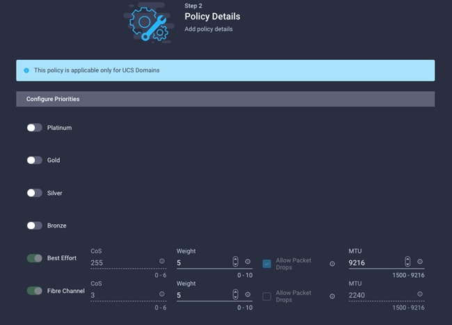
6. Click Create.
7. Click Next.
Verify all the settings including the fabric interconnect settings, by expanding the settings and make sure that the configuration is correct.
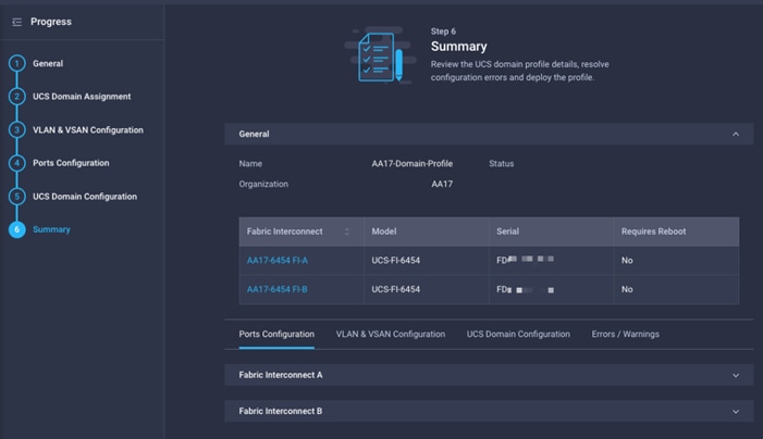
Deploy the Cisco UCS Domain Profile
After verifying the domain profile configuration, deploy the Cisco UCS profile.
1. From the UCS domain profile Summary view, Click Deploy.
2. Acknowledge any warnings and click Deploy again.
The system will take some time to validate and configure the settings on the fabric interconnects. Log into the console servers to see when the Cisco UCS fabric interconnects have finished configuration and are successfully rebooted.
Verify Cisco UCS Domain Profile Deployment
When the Cisco UCS domain profile has been successfully deployed, the Cisco UCS chassis and the blades should be successfully discovered.
![]() It takes a while to discover the blades for the first time. Watch the number of outstanding tasks in Cisco Intersight:
It takes a while to discover the blades for the first time. Watch the number of outstanding tasks in Cisco Intersight:
![]()
![]()
3. Log in to the Cisco Intersight. Under CONFIGURE > Profiles > UCS Domain Profiles, verify that the domain profile has been successfully deployed.
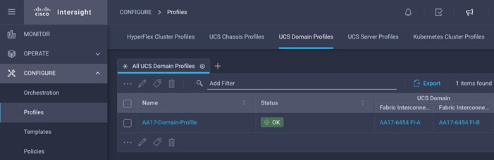
4. Verify that the chassis (in this deployment both UCSX-9508 and UCS 5108 chassis) has been discovered and is visible under OPERATE > Chassis.
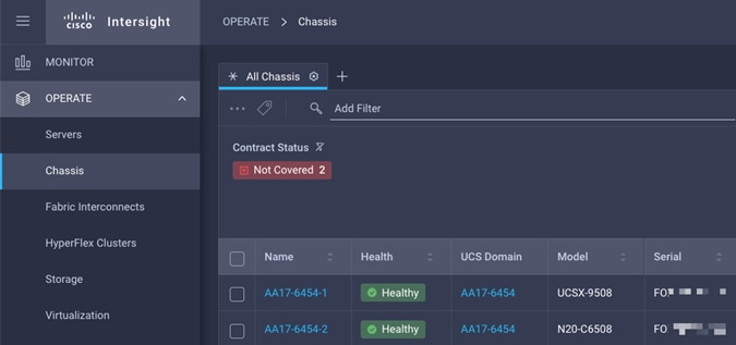
5. Verify that the servers have been successfully discovered and are visible under OPERATE > Servers.
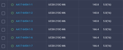

Configure Cisco UCS Chassis Profile
Cisco UCS Chassis profile in Cisco Intersight allow customers to configure various parameters for chassis, including:
● IMC Access Policy: IP configuration for the in-band chassis connectivity. This setting is independent of Server IP connectivity and only applies to communication to and from chassis.
● SNMP Policy, and SNMP trap settings.
● Power Policy to enable power management and power supply redundancy mode.
● Thermal Policy to control the speed of FANs (only applicable to Cisco UCS 5108)
A chassis policy can be assigned to any number of chassis profiles to provide a configuration baseline for a chassis. In this deployment, no chassis profile was created or attached to the chassis, but customers can configure policies to configure SNMP or Power parameters and attach them to the chassis.
Configure Server Profile Template
In the Cisco Intersight platform, a server profile enables resource management by simplifying policy alignment and server configuration. The server profiles are derived from a server profile template. Server profile template and its associated policies can be created using the server profile template wizard. After creating server profile template, customers can derive multiple consistent server profiles from the template.
![]() The server profile captured in this deployment guide supports both Cisco UCS B200 M6 blades and Cisco UCSX X210c M6 compute nodes.
The server profile captured in this deployment guide supports both Cisco UCS B200 M6 blades and Cisco UCSX X210c M6 compute nodes.
vNIC and vHBA Placement for Server Profile Template
In this deployment, separate server profile templates are created for iSCSI connected storage and for FC connected storage. The vNIC and vHBA layout is covered below. While most of the policies are common across various templates, the LAN connectivity and SAN connectivity policies are unique and will use the information in the tables below.
● Six vNICs are configured to support iSCSI boot from SAN. These vNICs are manually placed as follows:
Table 6. vNIC placement for iSCSI connected storage
| vNIC/vHBA Name |
Slot |
Switch ID |
PCI Order |
| 01-vSwitch0-A |
MLOM |
A |
0 |
| 02-vSwitch0-B |
MLOM |
B |
1 |
| 03-VDS0-A |
MLOM |
A |
2 |
| 04-VDS0-B |
MLOM |
B |
3 |
| 05-ISCSI-A |
MLOM |
A |
4 |
| 06-ISCSI-B |
MLOM |
B |
5 |
● Four vNICs and two vHBAs are configured to support FC boot from SAN. These devices are manually placed as follows:
Table 7. vHBA and vNIC placement for FC connected storage
| vNIC/vHBA Name |
Slot |
Switch ID |
PCI Order |
| vHBA-A |
MLOM |
A |
0 |
| vHBA-B |
MLOM |
B |
1 |
| 01-vSwitch0-A |
MLOM |
A |
2 |
| 02-vSwitch0-B |
MLOM |
B |
3 |
| 03-VDS0-A |
MLOM |
A |
4 |
| 04-VDS0-B |
MLOM |
B |
5 |
● Four vNICs and four vHBAs are configured to support FC boot from SAN. Two vHBAs (vHBA-A and vHBA-B) are used for boot from SAN connectivity and the remaining two vHBAs are used to support NVMe-o-FC. These devices are manually placed as follows:
Table 8. vHBA and vNIC placement for FC with NVMe-o-FC connected storage
| vNIC/vHBA Name |
Slot |
Switch ID |
PCI Order |
Comment |
| vHBA-A |
MLOM |
A |
0 |
Used for boot from SAN |
| vHBA-B |
MLOM |
B |
1 |
Used for boot from SAN |
| 01-vSwitch0-A |
MLOM |
A |
2 |
|
| 02-vSwitch0-B |
MLOM |
B |
3 |
|
| 03-VDS0-A |
MLOM |
A |
4 |
|
| 04-VDS0-B |
MLOM |
B |
5 |
|
| vHBA-NVMe-A |
MLOM |
A |
6 |
Used for NVMe-o-FC |
| vHBA-NVMe-B |
MLOM |
B |
7 |
Used for NVMe-o-FC |
Server Profile Template Creation
To configure a server profile template, follow these steps:
1. Log in to the Cisco Intersight.
2. Go to CONFIGURE > Templates and in the main window click Create UCS Server Profile Template.
Follow these steps for the general configuration:
1. Select the organization from the drop-down list (for example, AA17).
2. Provide a name for the server profile template. The names used in this deployment are:
● ISCSI-Boot-Template (iSCSI boot from SAN)
● FC-Boot-Template (FC boot from SAN)
● FC-Boot-NVME-Template (FC boot from SAN with support for NVMe-o-FC).
3. Select UCS Server (FI-Attached).
4. Provide an optional description.
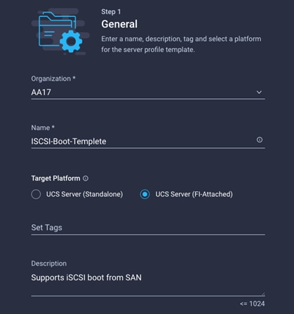
5. Click Next.
Step 2: Compute Configuration
Follow these steps to complete compute configuration:
Configure UUID Pool
1. Click Select Pool under UUID Pool and then in the pane on the right, click Create New.
2. Verify correct organization is selected from the drop-down list (for example, AA17) and provide a name for the UUID Pool (for example, AA17-UUID-Pool).
3. Provide an optional Description and click Next.
4. Provide a UUID Prefix (for example, a random prefix of 33FB3F9C-BF35-4BDE was used).
5. Add a UUID block.
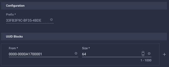
6. Click Create.
Configure BIOS policy
1. Click Select Policy next to BIOS and in the pane on the right, click Create New.
2. Verify correct organization is selected from the drop-down list (for example, AA17) and provide a name for the policy (for example, AA17-NTPPol).
3. Click Next.
4. On the Policy Details screen, select appropriate values for the BIOS settings. In this deployment, the BIOS values were selected based on recommendations in the performance tuning guide for Cisco UCS M6 BIOS: https://www.cisco.com/c/en/us/products/collateral/servers-unified-computing/ucs-b-series-blade-servers/performance-tuning-guide-ucs-m6-servers.html.
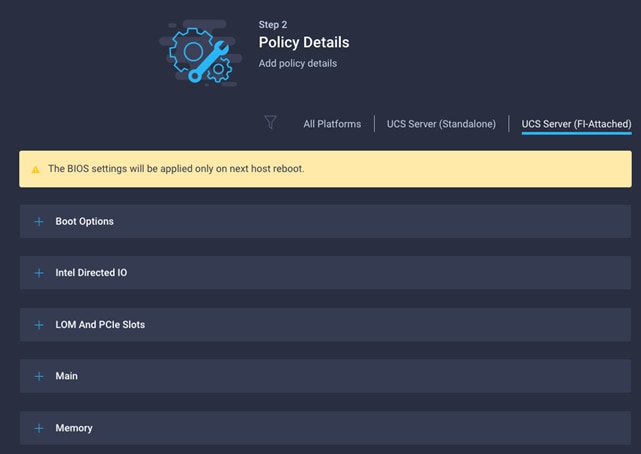
● LOM and PCIe Slot > CDN Support for LOM: Enabled
● Processor > Enhanced CPU performance: Auto
● Memory > NVM Performance Setting: Balanced Profile
5. Click Create.
Configure Boot Order Policy for iSCSI Hosts
Follow these steps to configure Boot Order policy for iSCSI hosts. The FC boot order policy is different from iSCSI boot policy and is covered next.
1. Click Select Policy next to BIOS Configuration and then, in the pane on the right, click Create New.
2. Verify correct organization is selected from the drop-down list (for example, AA17) and provide a name for the policy (for example, AA17-ISCSI-BootOrder-Pol).
3. Click Next.
4. For Configured Boot Mode, select Unified Extensible Firmware Interface (UEFI).
5. Turn on Enable Secure Boot.
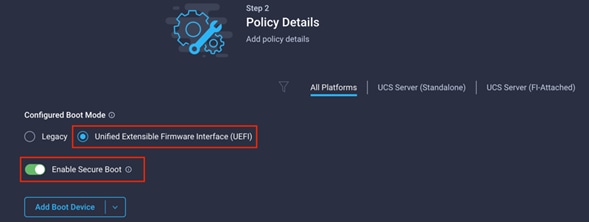
6. Click Add Boot Device drop-down list and select Virtual Media.
7. Provide a device name (for example, ISO) and then, for the subtype, select KVM Mapped DVD.

8. From the Add Boot Device drop-down list, select iSCSI Boot.
9. Provide the Device Name: ISCSI-A-Boot and the exact name of the interface used for iSCSI boot under Interface Name: 05-ISCSI-A.
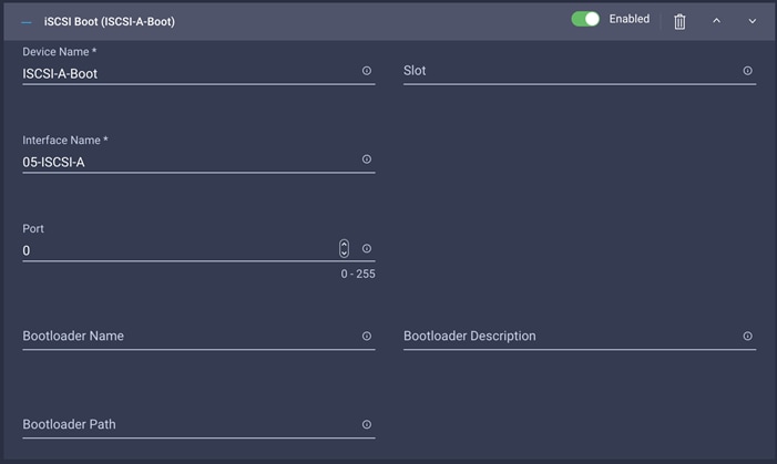
![]() The device names (ISCSI-A-Boot and ISCSI-B-Boot) are being defined here and will be used in the later steps of the ISCSI configuration.
The device names (ISCSI-A-Boot and ISCSI-B-Boot) are being defined here and will be used in the later steps of the ISCSI configuration.
10. From the Add Boot Device drop-down list, select iSCSI Boot.
11. Provide the Device Name: ISCSI-B-Boot and the exact name of the interface used for iSCSI boot under Interface Name: 06-ISCSI-B.
12. From the Add Boot Device drop-down list, select UEFI Shell.
13. Add Device Name UEFIShell.
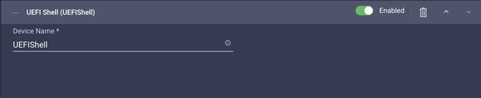
14. Verify the order of the boot policies and adjust the boot order as necessary using arrows next to delete button.
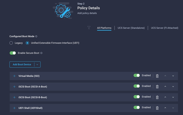
15. Click Create.
Configure Boot Order Policy for FC Hosts
Follow these steps to configure Boot Order policy for FC hosts. The FC boot order policy applies to all FC hosts including hosts that support NVMe-o-FC storage access.
1. Click Select Policy next to BIOS Configuration and then, in the pane on the right, click Create New.
2. Verify correct organization is selected from the drop-down list (for example, AA17) and provide a name for the policy (for example, AA17-FC-BootOrder-Pol).
3. Click Next.
4. For Configured Boot Mode, select Unified Extensible Firmware Interface (UEFI).
5. Turn on Enable Secure Boot.

6. Click Add Boot Device drop-down list and select Virtual Media.
7. Provide a device name (for example, ISO) and then, for the subtype, select KVM Mapped DVD.
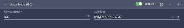
For Fibre Channel SAN boot, all four NetApp controller LIFs will be added as boot options. The four LIFs are named as follows:
● FCP-LIF01a: NetApp Controller 1, LIF for Fibre Channel SAN A
● FCP-LIF01b: NetApp Controller 1, LIF for Fibre Channel SAN B
● FCP-LIF02a: NetApp Controller 2, LIF for Fibre Channel SAN A
● FCP-LIF02b: NetApp Controller 2, LIF for Fibre Channel SAN B
8. From the Add Boot Device drop-down list, select SAN Boot.
9. Provide the Device Name: FCp-LIF01a and the Logical Unit Number (LUN) value (for example, 0).
10. Provide an interface name vHBA-A. This value is important and should match the vHBA name.
![]() vHBA-A is used to access FCP-LIF01a and FCP-LIF02a and vHBA-B is used to access FCP-LIF01b and FCP-LIF02b.
vHBA-A is used to access FCP-LIF01a and FCP-LIF02a and vHBA-B is used to access FCP-LIF01b and FCP-LIF02b.
11. Add the appropriate World Wide Port Name (WWPN) as the Target WWPN.
![]() To obtain the WWPN values, log into NetApp controller using SSH and enter the following command: network interface show -vserver Infra-SVM -data-protocol fcp.
To obtain the WWPN values, log into NetApp controller using SSH and enter the following command: network interface show -vserver Infra-SVM -data-protocol fcp.
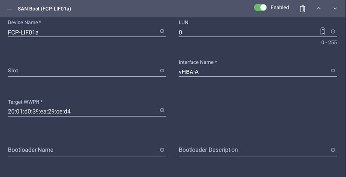
12. Repeat steps 8-11 three more times to add all the NetApp LIFs.
13. From the Add Boot Device drop-down list, select UEFI Shell.
14. Add Device Name UEFIShell.

15. Verify the order of the boot policies and adjust the boot order as necessary using the arrows next to the Delete button.
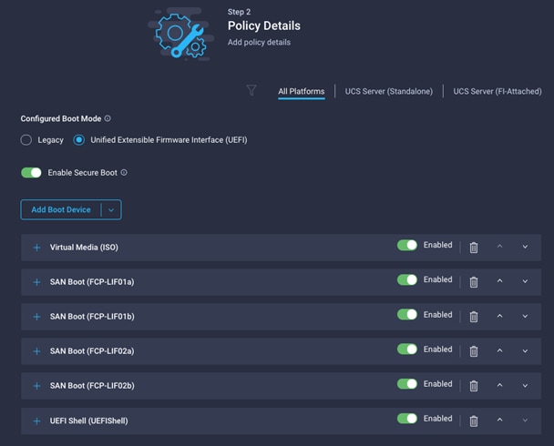
16. Click Create.
17. Click Next to move to Management Configuration.
Step 4: Management Configuration
Next, configure management policy. There policies will be added to the management configuration
· IMC Access to define the pool of IP addresses for compute node KVM access
· IPMI Over LAN to allow Intersight to manage IPMI messages
· Local User to provide local administrator to access KVM
Configure Cisco IMC Access Policy
Follow these steps to configure Cisco IMC access policy:
1. Click Select Policy next to IMC Access and then, in the pane on the right, click Create New.
2. Verify correct organization is selected from the drop-down list (for example, AA17) and provide a name for the policy (for example, AA17-IMC-Access).
3. Click Next.
![]() Customers can select in-band management access to the compute node using an in-band management VLAN (for example, VLAN 17) or out-of-band management access via the Mgmt0 interfaces of the FIs. KVM Policies like SNMP, vMedia and Syslog are currently not supported via Out-Of-Band and will require an In-Band IP to be configured. Since these policies were not configured in this deployment, out-of-band management access was configured so that KVM access to compute nodes is not impacted by any potential switching issues in the fabric.
Customers can select in-band management access to the compute node using an in-band management VLAN (for example, VLAN 17) or out-of-band management access via the Mgmt0 interfaces of the FIs. KVM Policies like SNMP, vMedia and Syslog are currently not supported via Out-Of-Band and will require an In-Band IP to be configured. Since these policies were not configured in this deployment, out-of-band management access was configured so that KVM access to compute nodes is not impacted by any potential switching issues in the fabric.
4. Click UCS Server (FI-Attached).
5. Enable Out-Of-Band Configuration.
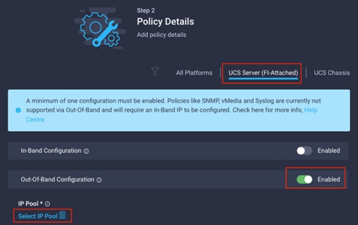
6. Under IP Pool, click Select IP Pool and then, in the pane on the right, click Create New.
7. Verify correct organization is selected from the drop-down list (for example, AA17) and provide a name for the policy (for example, AA17-IMC-OOB-Pool).
8. Select Configure IPv4 Pool and provide the information to define a pool for KVM IP address assignment including an IP Block.
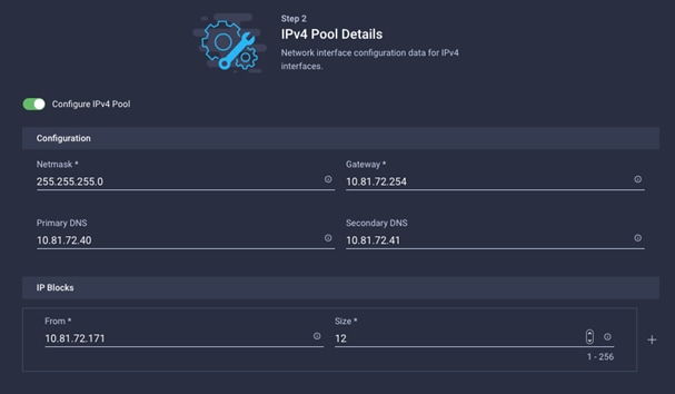
![]() The management IP pool subnet should be accessible from the host that is trying to open the KVM connection. In the example shown here, the hosts trying to open a KVM connection would need to be able to route to 10.81.72.0/24 subnet.
The management IP pool subnet should be accessible from the host that is trying to open the KVM connection. In the example shown here, the hosts trying to open a KVM connection would need to be able to route to 10.81.72.0/24 subnet.
9. Click Next.
10. Unselect Configure IPv6 Pool.
11. Click Create to finish configuring the IP address pool.
12. Click Create to finish configuring the IMC access policy.
Configure IPMI Over LAN policy
Follow these steps to configure IPMI Over LAN policy:
1. Click Select Policy next to IPMI Over LAN and then, in the pane on the right, click Create New.
2. Verify correct organization is selected from the drop-down list (for example, AA17) and provide a name for the policy (for example, Enable-IPMIoLAN).
3. Turn on Enable IPMI Over LAN.
4. From the Privilege Level drop-down list, select admin.
5. Click Create.
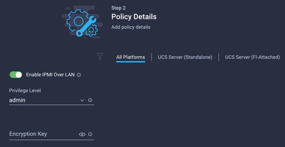
Follow these steps to configure local user policy:
1. Click Select Policy next to Local User and the, in the pane on the right, click Create New.
2. Verify correct organization is selected from the drop-down list (for example, AA17) and provide a name for the policy (for example, AA17-LocalUser-Pol).
3. Verify that UCS Server (FI-Attached) is selected.
4. Verify that Enforce Strong Password is selected.
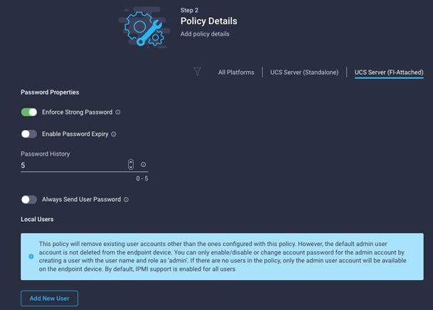
5. Click Add New User and then click + next to the New User
6. Provide the username (for example, fpadmin), choose a role for example, admin), and provide a password.
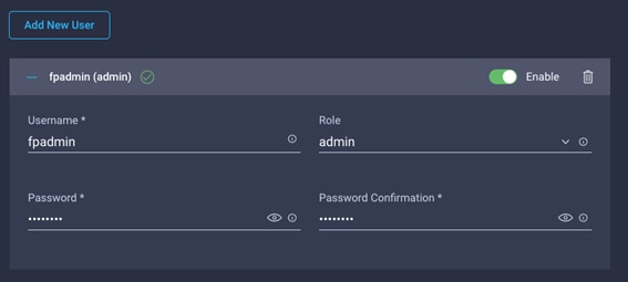
![]() The username and password combination defined here will be used to log in to KVMs. The typical Cisco UCS admin username and password combination cannot be used for KVM access.
The username and password combination defined here will be used to log in to KVMs. The typical Cisco UCS admin username and password combination cannot be used for KVM access.
7. Click Create to finish configuring the user.
8. Click Create to finish configuring local user policy.
9. Click Next to move to Storage Configuration.
Click Next on the Storage Configuration screen. No configuration is needed in the local storage system.
Step 6a: Network Configuration > LAN Connectivity
LAN connectivity policy defines the connections and network communication resources between the server and the LAN. This policy uses pools to assign MAC addresses to servers and to identify the vNICs that the servers use to communicate with the network. For iSCSI hosts, this policy also defined an IQN address pool.
For consistent vNIC and vHBA placement, manual vHBA/vNIC placement is utilized. ISCSI boot from SAN hosts and FC boot from SAN hosts require different number of vNICs/vHBAs and different placement order therefore the iSCSI host and the FC host LAN connectivity policies are covered separately in this section.
LAN Connectivity Policy for iSCSI hosts.
The iSCSI boot from SAN hosts uses 6 vNICs configured as follows:
Table 9. vNICs for iSCSI LAN Connectivity
| vNIC/vHBA Name |
Slot ID |
Switch ID |
PCI Order |
VLANs |
| 01-vSwitch0-A |
MLOM |
A |
0 |
IB-MGMT, NFS |
| 02-vSwitch0-B |
MLOM |
B |
1 |
IB-MGMT, NFS |
| 03-VDS0-A |
MLOM |
A |
2 |
VM Traffic, vMotion |
| 04-VDS0-B |
MLOM |
B |
3 |
VM Traffic, vMotion |
| 05-ISCSI-A |
MLOM |
A |
4 |
iSCSI-A-VLAN |
| 06-ISCSI-B |
MLOM |
B |
5 |
iSCSI-B-VLAN |
Follow these steps to create LAN connectivity policy for iSCSI hosts:
1. Click Select Policy next to LAN Connectivity and then, in the pane on the right, click Create New.
2. Verify correct organization is selected from the drop-down list (for example, AA17) and provide a name for the policy (for example, AA17-ISCSI-ESXi-LanConn). Click Next.
3. Under IQN, select Pool.
4. Click on Select Pool under IQN Pool and then, in the pane on the right, click Create New.
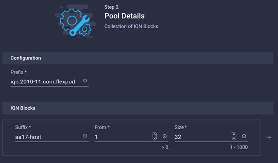
5. Verify correct organization is selected from the drop-down list (for example, AA17) and provide a name for the IQN Pool (for example, AA17-IQN Pool).
6. Click Next.
7. Provide the values for Prefix and IQN Block to create the IQN pool.

8. Click Create.
9. Under vNIC Configuration, select Manual vNICs Placement.
10. Click Add vNIC.
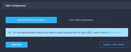
Create MAC address pool
When creating the first vNIC, the MAC address pool has not been defined yet therefore a new MAC address pool will need to be created. Two separate MAC address pools are configured for each Fabric. MAC-Pool-A will be reused for all Fabric-A vNICs, and MAC-Pool-B will be reused for all Fabric-B vNICs.
Table 10. MAC Address Pools
| Pool Name |
Starting MAC Address |
Size |
vNICs |
| MAC-Pool-A |
00:25:B5:17:0A:00 |
64* |
01-vSwitch0-A, 03-VDS0-A, 05-ISCSI-A |
| MAC-Pool-B |
00:25:B5:17:0B:00 |
64* |
02-vSwitch0-B, 04-VDS0-B, 06-ISCSI-B |
![]() Each server requires 3 MAC addresses from the pool. Adjust the size of the pool according to your requirements.
Each server requires 3 MAC addresses from the pool. Adjust the size of the pool according to your requirements.
To define the MAC pool for Fabric A/B:
1. Click Select Pool under MAC Address Pool and then, in the pane on the right, click Create New.
2. Verify correct organization is selected from the drop-down list (for example, AA17) and provide a name for the pool from Table 10 depending on the vNIC being created (for example, MAC-Pool-A for Fabric A).
3. Click Next.
4. Provide the starting MAC address from Table 10 (for example, 00:25:B5:17:0A:00)
![]() For ease of troubleshooting FlexPod, some additional information is always coded into the MAC address pool. For example, in the starting address 00:25:B5:17:0A:00, 17 is the rack ID and 0A indicates Fabric A.
For ease of troubleshooting FlexPod, some additional information is always coded into the MAC address pool. For example, in the starting address 00:25:B5:17:0A:00, 17 is the rack ID and 0A indicates Fabric A.
5. Provide the size of the MAC address pool from Table 10 (for example, 64).
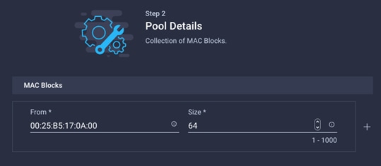
6. Click Create to finish creating the MAC address pool.
Back in the Add vNIC window:
7. Provide vNIC Name, Slot ID, Switch ID and PCI Order information from Table 9.
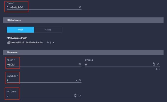
8. For Consistent Device Naming (CDN), from the drop-down list, select vNIC Name.
9. Verify that Failover is disabled because the failover will be provided by attaching multiple NICs to the VMware vSwitch and VDS.
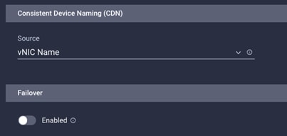
Create Ethernet Network Group Policy
Ethernet Network Group policies will be created and reused on applicable vNICs as covered below. Ethernet network group policy defines the VLANs allowed for a particular vNIC therefore multiple network group policies will be defined for this deployment as follows:
Table 11. Ethernet Group Policy Values
| Group Policy Name |
Native VLAN |
Apply to vNICs |
VLANs |
| AA17-vSwitch0-NetGrp |
Native-VLAN (2) |
01-vSwitch0-A, 02-vSwitch0-B |
IB-MGMT, NFS |
| AA17-VDS0-NetGrp |
Native-VLAN (2) |
03-VDS0-A, 04-VDS0-B |
VM Traffic, vMotion |
| AA17-ISCSI-A-NetGrp |
iSCSI-A-VLAN |
05-ISCSI-A |
iSCSI-A-VLAN |
| AA17- ISCSI-B-NetGrp |
iSCSI-B-VLAN |
06-ISCSI-B |
iSCSI-B-VLAN |
To define Ethernet Group Policy for a vNIC, follow these steps:
10. Click Select Policy under Ethernet Network Group Policy and then, in the pane on the right, click Create New.
11. Verify correct organization is selected from the drop-down list (for example, AA17) and provide a name for the policy from the Table 11 (for example, AA17-vSwitch0-NetGrp).
12. Click Next.
13. Enter the allowed VLANs (for example, 17,3017) and the native VLAN ID from Table 11 (for example, 2).
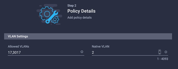
14. Click Create to finish configuring the Ethernet network group policy.
![]() When ethernet group policies are shared between two vNICs, the ethernet group policy only needs to be defined for the first vNIC. For subsequent vNIC policy mapping, just click Select Policy and pick the previously defined ethernet group policy from the list.
When ethernet group policies are shared between two vNICs, the ethernet group policy only needs to be defined for the first vNIC. For subsequent vNIC policy mapping, just click Select Policy and pick the previously defined ethernet group policy from the list.
Create Ethernet Network Control Policy
Ethernet Network Control Policy is used to enable Cisco Discovery Protocol (CDP) and Link Layer Discovery Protocol (LLDP) for the vNICs. A single policy will be created here and reused for all the vNICs.
To create the Ethernet Network Control Policy, follow these steps:
1. Click Select Policy under Ethernet Network Control Policy and then, in the pane on the right, click Create New.
2. Verify correct organization is selected from the drop-down list (for example, AA17) and provide a name for the policy (for example, AA17-Enable-CDP-LLDP).
3. Click Next.
4. Enable Cisco Discovery Protocol and both Enable Transmit and Enable Receive under LLDP.
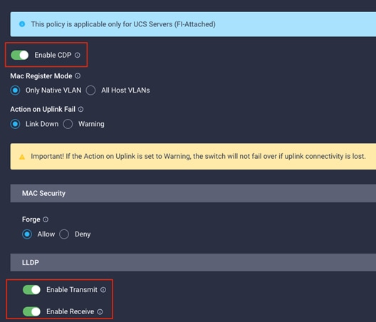
5. Click Create to finish creating Ethernet network control policy.
Create Ethernet QoS policy
Ethernet QoS policy is used to enable jumbo maximum transmission units (MTUs) for all the vNICs. A single policy will be created and reused for all the vNICs.
1. Click Select Policy under Ethernet QoS and in the pane on the right, click Create New.
2. Verify correct organization is selected from the drop-down list (for example, AA17) and provide a name for the policy (for example, AA17-EthQos-Pol).
3. Click Next.
4. Change the MTU, Bytes value to 9000.

5. Click Create to finish setting up the Ethernet QoS policy.
Create Ethernet Adapter Policy
Ethernet adapter policy is used to set the interrupts and the send and receive queues. The values are set according to the best-practices guidance for the operating system in use. Cisco Intersight provides default VMware Ethernet Adapter policy for typical VMware deployments.
Customers can optionally configure a tweaked ethernet adapter policy for additional hardware receive queues handled by multiple CPUs in scenarios where there is a lot of vMotion traffic and multiple flows. In this deployment, a modified ethernet adapter policy, AA17-VMware-High-Traffic, is created and attached to the 03-VDS0-A and 04-VDS0-B interfaces which handle vMotion.
Table 12. Ethernet Adapter Policy association to vNICs
| Policy Name |
vNICs |
| AA17-EthAdapter-VMware |
01-vSwitch0-A, 02-vSwitch0-B, 05-ISCSI-A, 06-ISCSI-B |
| AA17-VMware-High-Traffic |
03-VDS0-A, 04-VDS0-B, |
1. Click Select Policy under Ethernet Adapter and then, in the pane on the right, click Create New.
2. Verify correct organization is selected from the drop-down list (for example, AA17) and provide a name for the policy (for example, AA17-EthAdapter-VMware).
3. Click Select Default Configuration under Ethernet Adapter Default Configuration.
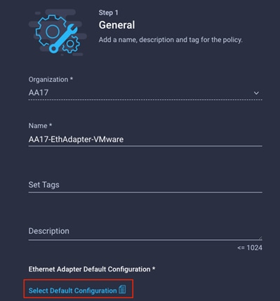
4. From the list, select VMware.
5. Click Next.
6. For the AA17-EthAdapter-VMware policy, click Create and skip the rest of the steps in this “Create Ethernet Adapter Policy” section.
7. For the optional AA17-VMware-High-Traffic policy (for VDS interfaces), make the following modifications to the policy:
● Increase Interrupts to 11
● Increase Receive Queue Count to 8
● Increase Completion Queue Count to 9
● Enable Receive Side Scaling
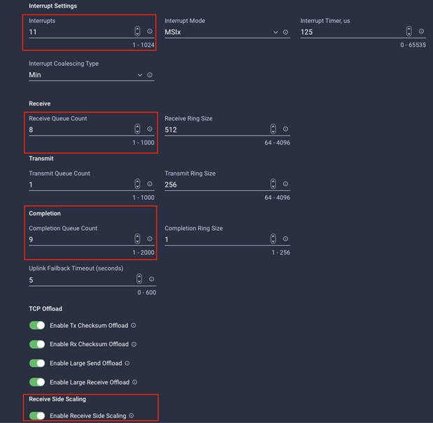
8. Click Create.
![]() For all the non-ISCSI VNIC, skip past the iSCSI-A and iSCSI-B policy creation sections
For all the non-ISCSI VNIC, skip past the iSCSI-A and iSCSI-B policy creation sections
Create iSCSI-A Policy
iSCSI-A policy only applied to vNICs 05-ISCSI-A and should not be created for data vNICs (vSwitch0 and VDS). The iSCSI-B policy creation is covered next.
To create this policy, the following information will be gathered from NetApp:
iSCSI Target:
AA17-A400::> iscsi show -vserver Infra-SVM
Vserver: Infra-SVM
Target Name: iqn.1992-08.com.netapp:sn.63144a05ad1211eb8a7ad039ea29d44a:vs.3
Target Alias: Infra-SVM
Administrative Status: up
iSCSI LIFs:
network interface show -vserver Infra-SVM -data-protocol iscsi
To create the iSCSI boot policy, follow these steps:
1. Click Select Policy under iSCSI Boot and then, in the pane on the right, click Create New.
2. Verify correct organization is selected from the drop-down list (for example, AA17) and provide a name for the policy (for example, AA17-ISCSI-Boot-A).
3. Click Next.
4. Select Static under Configuration.
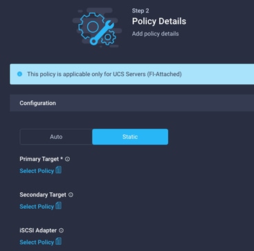
5. Click Select Policy under Primary Target and then, in the pane on the right, click Create New.
6. Verify correct organization is selected from the drop-down list (for example, AA17) and provide a name for the policy (for example, AA17-ISCSI-A-Primary-Target).
7. Click Next.
8. Provide the Target Name captured from NetApp, IP Address of iscsi-lif01a, Port 3260 and Lun ID of 0
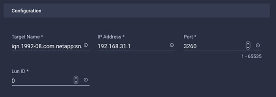
9. Click Create.
10. Click Select Policy under Secondary Target and then, in the pane on the right, click Create New.
11. Verify correct organization is selected from the drop-down list (for example, AA17) and provide a name for the policy (for example, AA17-ISCSI-A-Secondary-Target).
12. Click Next.
13. Provide the Target Name captured from NetApp, IP Address of iscsi-lif02a, Port 3260 and Lun ID of 0
14. Click Create.
15. Click Select Policy under iSCSI Adapter and then, in the pane on the right, click Create New.
16. Verify correct organization is selected from the drop-down list (for example, AA17) and provide a name for the policy (for example, AA17-ISCSI-AdapterPol).
17. Click Next.
18. Accept the default policies. Customers can adjust the timers if necessary.
19. Click Create.
20. Scroll down to Initiator IP Source and make sure Pool is selected.
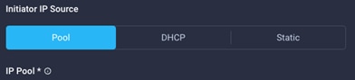
21. Click Select Pool under IP Pool and then, in the pane on the right, click Create New.
22. Verify correct organization is selected from the drop-down list (for example, AA17) and provide a name for the pool (for example, AA17-ISCSI-A-Pool).
23. Click Next.
24. Make sure Configure IPv4 Pool is selected. Enter the IP pool information for iSCSI-A subnet.
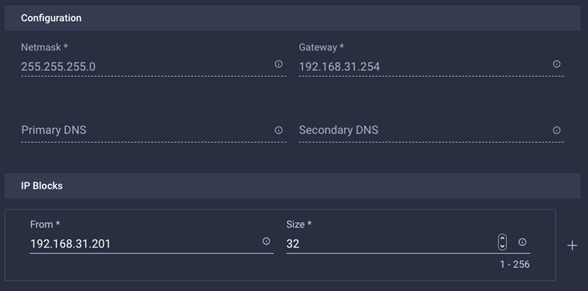
![]() Since the iSCSI network is not routable and all the VMkernel ports and LIFs are layer-2 adjacent, there is no need to define a gateway or DNS.
Since the iSCSI network is not routable and all the VMkernel ports and LIFs are layer-2 adjacent, there is no need to define a gateway or DNS.
25. Click Next.
26. Disable Configure IPv6 Pool.
27. Click Create.
28. Verify all the policies and pools are correctly mapped for the iSCSI-A policy.
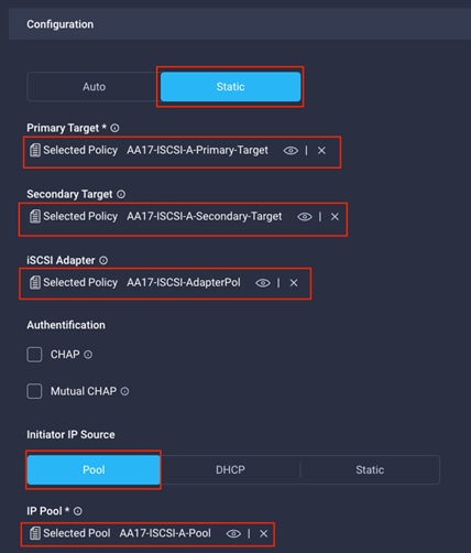
29. Click Create.
Create iSCSI-B Policy
iSCSI-B policy only applied to vNICs 06-ISCSI-B and should not be created for data vNICs (vSwitch0 and VDS).
To create this policy, following information will be gathered from NetApp:
iSCSI Target:
AA17-A400::> iscsi show -vserver Infra-SVM
Vserver: Infra-SVM
Target Name: iqn.1992-08.com.netapp:sn.63144a05ad1211eb8a7ad039ea29d44a:vs.3
Target Alias: Infra-SVM
Administrative Status: up
iSCSI LIFs:
network interface show -vserver Infra-SVM -data-protocol iscsi
To create the iSCSI boot policy, follow these steps:
1. Click Select Policy under iSCSI Boot and then, in the pane on the right, click Create New.
2. Verify correct organization is selected from the drop-down list (for example, AA17) and provide a name for the policy (for example, AA17-ISCSI-Boot-B).
3. Click Next.
4. Select Static under Configuration.
5. Click Select Policy under Primary Target and then, in the pane on the right, click Create New.
6. Verify correct organization is selected from the drop-down list (for example, AA17) and provide a name for the policy (for example, AA17-ISCSI-B-Primary-Target).
7. Click Next.
8. Provide the Target Name captured from NetApp, IP Address of iscsi-lif01b, Port 3260 and Lun ID of 0
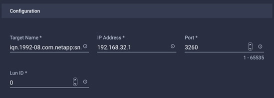
9. Click Create.
10. Click Select Policy under Secondary Target and then, in the pane on the right, click Create New.
11. Verify correct organization is selected from the drop-down list (for example, AA17) and provide a name for the policy (for example, AA17-ISCSI-B-Secondary-Target).
12. Click Next.
13. Provide the Target Name captured from NetApp, IP Address of iscsi-lif02b, Port 3260 and Lun ID of 0
14. Click Create.
15. Click Select Policy under iSCSI Adapter and then, in the pane on the right, select the previously configured adapter policy AA17-ISCSI-AdapterPol).
16. Scroll down to Initiator IP Source and make sure Pool is selected.
17. Click Select Pool under IP Pool and then, in the pane on the right, click Create New.
18. Verify correct organization is selected from the drop-down list (for example, AA17) and provide a name for the pool (for example, AA17-ISCSI-B-Pool).
19. Click Next.
20. Make sure Configure IPv4 Pool is selected. Enter the IP pool information for iSCSI-B subnet.
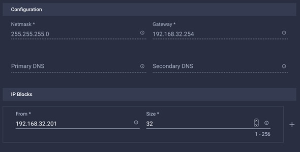
![]() Since the iSCSI network is not routable and all the VMkernel ports and LIFs are layer-2 adjacent, there is no need to define a gateway or DNS.
Since the iSCSI network is not routable and all the VMkernel ports and LIFs are layer-2 adjacent, there is no need to define a gateway or DNS.
21. Click Next.
22. Disable Configure IPv6 Pool.
23. Click Create.
24. Verify all the policies and pools are correctly mapped for the iSCSI-B policy.
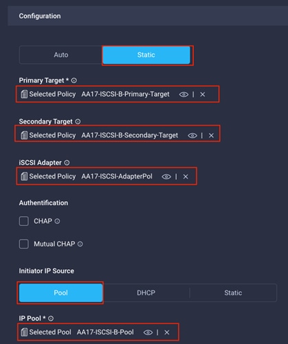
25. Click Create.
26. Click Create to finish creating the vNIC.
27. Jump back to step 10 Add vNIC and repeat vNIC creation for all six vNICs.
28. Verify all six vNICs were successfully created.
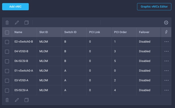
29. Click Create to finish creating the LAN Connectivity policy for iSCSI hosts.
LAN Connectivity Policy for FC hosts.
The FC boot from SAN hosts uses 4 vNICs configured as follows:
Table 13. vNICs for FC LAN Connectivity
| vNIC/vHBA Name |
Slot ID |
Switch ID |
PCI Order |
VLANs |
| 01-vSwitch0-A |
MLOM |
A |
2 |
IB-MGMT, NFS |
| 02-vSwitch0-B |
MLOM |
B |
3 |
IB-MGMT, NFS |
| 03-VDS0-A |
MLOM |
A |
4 |
VM Traffic, vMotion |
| 04-VDS0-B |
MLOM |
B |
5 |
VM Traffic, vMotion |
![]() The PCI order 0 and 1 will be used in the SAN Connectivity policy to create vHBA-A and vHBA-B.
The PCI order 0 and 1 will be used in the SAN Connectivity policy to create vHBA-A and vHBA-B.
Follow these steps to create LAN connectivity for FC hosts:
1. Click Select Policy next to LAN Connectivity and then, in the pane on the right, click Create New.
2. Verify correct organization is selected from the drop-down list (for example, AA17) and provide a name for the policy (for example, AA17-FC-ESXi-LanConn). Click Next.
3. Under vNIC Configuration, select Manual vNICs Placement.
4. Click Add vNIC.
Create MAC Address Pool
When creating the first vNIC, the MAC address pool has not been defined yet therefore a new MAC address pool will need to be created. Two separate MAC address pools are configured for each Fabric. MAC-Pool-A will be reused for all Fabric-A vNICs, and MAC-Pool-B will be reused for all Fabric-B vNICs.
Table 14. MAC Address Pools
| Pool Name |
Starting MAC Address |
Size |
vNICs |
| MAC-Pool-A |
00:25:B5:17:0A:00 |
64* |
01-vSwitch0-A, 03-VDS0-A |
| MAC-Pool-B |
00:25:B5:17:0B:00 |
64* |
02-vSwitch0-B, 04-VDS0-B |
![]() Each server requires 2 MAC addresses from the pool. Adjust the size of the pool according to your requirements.
Each server requires 2 MAC addresses from the pool. Adjust the size of the pool according to your requirements.
To define the MAC pool for Fabric A/B, follow these steps:
1. Click Select Pool under MAC Address Pool and then, in the pane on the right, click Create New.
2. Verify correct organization is selected from the drop-down list (for example, AA17) and provide a name for the pool from Table 14 depending on the vNIC being created (for example, MAC-Pool-A for Fabric A).
3. Click Next.
4. Provide the starting MAC address from Table 14 (for example, 00:25:B5:17:0A:00)
![]() For ease of troubleshooting FlexPod, some additional information is always coded into the MAC address pool. For example, in the starting address 00:25:B5:17:0A:00, 17 is the rack ID and 0A indicates Fabric A.
For ease of troubleshooting FlexPod, some additional information is always coded into the MAC address pool. For example, in the starting address 00:25:B5:17:0A:00, 17 is the rack ID and 0A indicates Fabric A.
5. Provide the size of the MAC address pool from Table 14 (for example, 64).
6. Click Create to finish creating the MAC address pool.
Back in the Add vNIC window:
7. Provide vNIC Name, Slot ID, Switch ID and PCI Order information from Table 13.
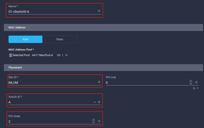
8. For Consistent Device Naming (CDN), from the drop-down list, select vNIC Name.
9. Verify that Failover is disabled because the failover will be provided by attaching multiple NICs to the VMware vSwitch and VDS.
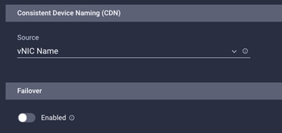
Create Ethernet Network Group Policy
Ethernet Network Group policies will be created and reused on applicable vNICs as covered below. Ethernet network group policy defines the VLANs allowed for a particular vNIC therefore multiple network group policies will be defined for this deployment as follows:
Table 15. Ethernet Group Policy Values
| Group Policy Name |
Native VLAN |
Apply to vNICs |
VLANs |
| AA17-vSwitch0-NetGrp |
Native-VLAN (2) |
01-vSwitch0-A, 02-vSwitch0-B |
IB-MGMT, NFS |
| AA17-VDS0-NetGrp |
Native-VLAN (2) |
03-VDS0-A, 04-VDS0-B |
VM Traffic, vMotion |
To define Ethernet Group Policy for a vNIC, follow these steps:
1. Click Select Policy under Ethernet Network Group Policy and then, in the pane on the right, click Create New.
2. Verify correct organization is selected from the drop-down list (for example, AA17) and provide a name for the policy from the Table 15 (for example, AA17-vSwitch0-NetGrp).
3. Click Next.
4. Enter the allowed VLANs (for example, 17,3017) and the native VLAN ID from Table 15 (for example, 2).
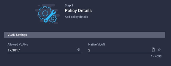
5. Click Create to finish configuring the Ethernet network group policy.
![]() When ethernet group policies are shared between two vNICs, the ethernet group policy only needs to be defined for the first vNIC. For subsequent vNIC policy mapping, just click Select Policy and pick the previously defined ethernet group policy from the list on the right.
When ethernet group policies are shared between two vNICs, the ethernet group policy only needs to be defined for the first vNIC. For subsequent vNIC policy mapping, just click Select Policy and pick the previously defined ethernet group policy from the list on the right.
Create Ethernet Network Control Policy
Ethernet Network Control Policy is used to enable Cisco Discovery Protocol (CDP) and Link Layer Discovery Protocol (LLDP) for the vNICs. A single policy will be created here and reused for all the vNICs.
To create the Ethernet Network Control Policy, follow these steps:
1. Click Select Policy under Ethernet Network Control Policy and then, in the pane on the right, click Create New.
2. Verify correct organization is selected from the drop-down list (for example, AA17) and provide a name for the policy (for example, AA17-Enable-CDP-LLDP).
3. Click Next.
4. Enable Cisco Discovery Protocol and both Enable Transmit and Enable Receive under LLDP.
5. Click Create to finish creating Ethernet network control policy.
Create Ethernet QoS Policy
Ethernet QoS policy is used to enable jumbo maximum transmission units (MTUs) for all the vNICs. A single policy is created and reused for all the vNICs. To create the ethernet QoS policy, follow these steps:
1. Click Select Policy under Ethernet QoS and in the pane on the right, click Create New.
2. Verify correct organization is selected from the drop-down list (for example, AA17) and provide a name for the policy (for example, AA17-EthQos-Pol).
3. Click Next.
4. Change the MTU, Bytes value to 9000.
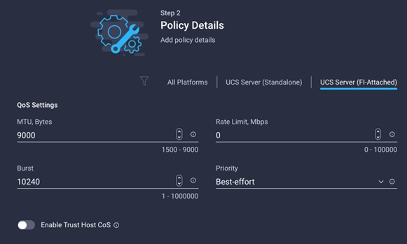
5. Click Create to finish setting up the Ethernet QoS policy.
Create Ethernet Adapter Policy
Ethernet adapter policy is used to set the interrupts and the send and receive queues. The values are set according to the best-practices guidance for the operating system in use. Cisco Intersight provides default VMware Ethernet Adapter policy for typical VMware deployments.
Customers can optionally configure a tweaked ethernet adapter policy for additional hardware receive queues handled by multiple CPUs in scenarios where there is a lot of vMotion traffic and multiple flows. In this deployment, a modified ethernet adapter policy, AA17-VMware-High-Traffic, is created and attached to the 03-VDS0-A and 04-VDS0-B interfaces which handle vMotion.
Table 16. Ethernet Adapter Policy association to vNICs
| Policy Name |
vNICs |
| AA17-EthAdapter-VMware |
01-vSwitch0-A, 02-vSwitch0-B |
| AA17-VMware-High-Traffic |
03-VDS0-A, 04-VDS0-B, |
To create the ethernet adapter policy, follow these steps:
1. Click Select Policy under Ethernet Adapter and then, in the pane on the right, click Create New.
2. Verify correct organization is selected from the drop-down list (for example, AA17) and provide a name for the policy (for example, AA17-EthAdapter-VMware).
3. Click Select Default Configuration under Ethernet Adapter Default Configuration.

4. From the list, select VMware.
5. Click Next.
6. For the AA17-EthAdapter-VMware policy, click Create and skip the rest of the steps in this “Create Ethernet Adapter Policy” section.
7. For the optional AA17-VMware-High-Traffic policy (for VDS interfaces), make the following modifications to the policy:
● Increase Interrupts to 11
● Increase Receive Queue Count to 8
● Increase Completion Queue Count to 9
● Enable Receive Side Scaling

8. Click Create.
9. Click Create to finish creating the vNIC.
10. Jump back to step 4 (Add vNIC) and repeat vNIC creation for all four vNICs.
11. Verify all four vNICs were successfully created.
12. Click Create to finish creating the LAN Connectivity policy for FC hosts.
Step 6b: Network Connectivity > SAN Connectivity
A SAN connectivity policy determines the network storage resources and the connections between the server and the storage device on the network. This policy enables customers to configure the vHBAs that the servers use to communicate with the SAN.
![]() SAN Connectivity policy is not needed for iSCSI boot from SAN hosts and can be skipped.
SAN Connectivity policy is not needed for iSCSI boot from SAN hosts and can be skipped.
Table 17 lists the details of two vHBAs that are used to provide FC connectivity and boot from SAN functionality.
Table 17. vHBA for boot from FC SAN
| vNIC/vHBA Name |
Slot |
Switch ID |
PCI Order |
| vHBA-A |
MLOM |
A |
0 |
| vHBA-B |
MLOM |
B |
1 |
To create the SAN connectivity policy, follow these steps:
1. Click Select Policy next to SAN Connectivity and then, in the pane on the right, click Create New.
2. Verify correct organization is selected from the drop-down list (for example, AA17) and provide a name for the policy (for example, AA17-SanConn-Pol).
3. Select Manual vHBAs Placement.
4. Select Pool under WWNN Address.
Create the WWNN Address Pool
The WWNN address pools have not been defined yet therefore a new WWNN address pool has to be defined. To create the WWNN address pool, follow these steps:
1. Click Select Pool under WWNN Address Pool and then, in the pane on the right, click Create New.
2. Verify correct organization is selected from the drop-down list (for example, AA17) and provide a name for the policy (for example, AA17-WWNN-Pool).
3. Click Next.
4. Provide the starting WWNN block address and the size of the pool.
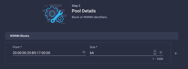
![]() As a best practice, in FlexPod some additional information is always coded into the WWNN address pool for ease of troubleshooting. For example, in the address 20:00:00:25:B5:17:00:00, 17 is the rack ID.
As a best practice, in FlexPod some additional information is always coded into the WWNN address pool for ease of troubleshooting. For example, in the address 20:00:00:25:B5:17:00:00, 17 is the rack ID.
5. Click Create to finish creating the WWNN address pool.
Create the vHBA-A for SAN A
To create a vHBA for SAN A, follow these steps:
1. Click Add vHBA.
2. For vHBA Type, select fc-initiator from the drop-down list.
Create the WWPN Pool for SAN A
The WWPN address pool has not been defined yet therefore a WWPN address pool for Fabric A will be defined. This pool will also be used for the NVMe-o-FC vHBAs if the vHBAs are defined. To create the WWPN pool for SAN A, follow these steps:
1. Click Select Pool under WWPN Address Pool and then, in the pane on the right, click Create New.
2. Verify correct organization is selected from the drop-down list (for example, AA17) and provide a name for the policy (for example, AA17-WWPN-Pool-A).
3. Provide the starting WWPN block address for SAN A and the size.
![]() As a best practice, in FlexPod some additional information is always coded into the WWPN address pool for ease of troubleshooting. For example, in the address 20:00:00:25:B5:17:0A:00, 17 is the rack ID and 0A signifies SAN A.
As a best practice, in FlexPod some additional information is always coded into the WWPN address pool for ease of troubleshooting. For example, in the address 20:00:00:25:B5:17:0A:00, 17 is the rack ID and 0A signifies SAN A.

4. Click Create to finish creating the WWPN pool.
5. Back in the Create vHBA window, provide the Name (for example, vHBA-A), Switch ID (for example, A) and PCI Order from Table 17.

Create Fibre Channel Network Policy for SAN A
A Fibre Channel network policy governs the VSAN configuration for the virtual interfaces. In this deployment, VSAN 101 will be used for vHBA-A. To create the fibre channel network policy for SAN A, follow these steps:
1. Click Select Policy under Fibre Channel Network and then, in the pane on the right, click Create New.
2. Verify correct organization is selected from the drop-down list (for example, AA17) and provide a name for the policy (for example, AA17-SAN-A-Network).
3. For the scope, select UCS Server (FI-Attached).
4. Under VSAN ID, provide the VSAN information (for example, 101).
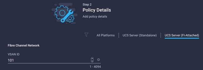
5. Click Create to finish creating the Fibre Channel network policy.
Create Fibre Channel QoS Policy
The Fibre Channel QoS policy assigns a system class to the outgoing traffic for a vHBA. This system class determines the quality of service for the outgoing traffic. The Fibre Channel QoS policy used in this deployment uses default values and will be shared by all vHBAs. To create the fibre channel QoS policy , follow these steps:
1. Click Select Policy under Fibre Channel QoS and then, in the pane on the right, click Create New.
2. Verify correct organization is selected from the drop-down list (for example, AA17) and provide a name for the policy (for example, AA17-FC-QoS).
3. For the scope, select UCS Server (FI-Attached).
4. Do not change the default values on the Policy Details screen.
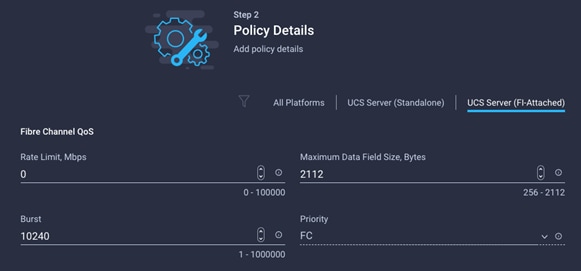
5. Click Create to finish creating the Fibre Channel QoS policy.
Create Fibre Channel Adapter Policy
A Fibre Channel adapter policy governs the host-side behavior of the adapter, including the way that the adapter handles traffic. This validation uses the default values for the adapter policy, and the policy will be shared by all the vHBAs. To create the fibre channel adapter policy, follow these steps:
1. Click Select Policy under Fibre Channel Adapter and then, in the pane on the right, click Create New.
2. Verify correct organization is selected from the drop-down list (for example, AA17) and provide a name for the policy (for example, AA17-FC-Adapter).
3. For the scope, select UCS Server (FI-Attached).
4. Do not change the default values on the Policy Details screen.
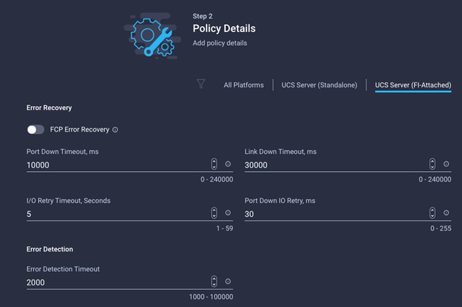
5. Click Create to finish creating the Fibre Channel adapter policy.
6. Click Add to create vHBA-A.
Create the vHBA for SAN B
To add vHBA-B for SAN B, follow these steps:
1. Click Add vHBA.
2. For vHBA Type, select fc-initiator from the drop-down list.
Create the WWPN Pool for SAN B
The WWPN address pool has not been defined yet therefore a WWPN address pool for Fabric B will be defined. This pool will also be used for the NVMe-o-FC vHBAs if the vHBAs are defined. To create the WWPN pool for SAN B, follow these steps:
1. Click Select Pool under WWPN Address Pool and then, in the pane on the right, click Create New.
2. Verify correct organization is selected from the drop-down list (for example, AA17) and provide a name for the policy (for example, AA17-WWPN-Pool-B).
3. Provide the starting WWPN block address for SAN B and the size.
![]() As a best practice, in FlexPod some additional information is always coded into the WWPN address pool for ease of troubleshooting. For example, in the address 20:00:00:25:B5:17:0B:00, 17 is the rack ID and 0B signifies SAN B.
As a best practice, in FlexPod some additional information is always coded into the WWPN address pool for ease of troubleshooting. For example, in the address 20:00:00:25:B5:17:0B:00, 17 is the rack ID and 0B signifies SAN B.
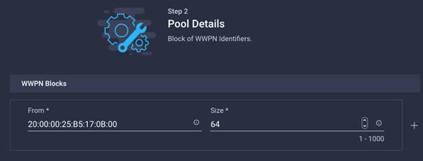
4. Click Create to finish creating the WWPN pool.
5. Back in the Create vHBA window, provide the Name (for example, vHBA-B), Switch ID (for example, B) and PCI Order from Table 17.
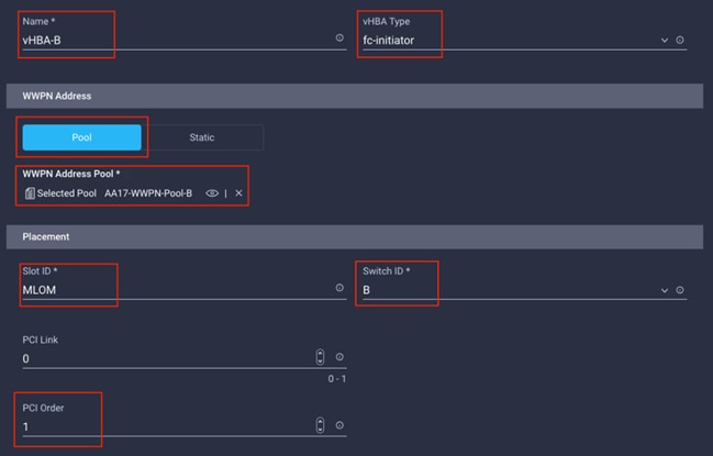
Create Fibre Channel Network Policy for SAN B
In this deployment, VSAN 102 will be used for vHBA-B. To create the fibre channel network policy for SAN B, follow these steps:
1. Click Select Policy under Fibre Channel Network and then, in the pane on the right, click Create New.
2. Verify correct organization is selected from the drop-down list (for example, AA17) and provide a name for the policy (for example, AA17-SAN-B-Network).
3. For the scope, select UCS Server (FI-Attached).
4. Under VSAN ID, provide the VSAN information (for example, 102).
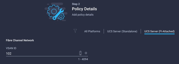
5. Click Create.
Select Fibre Channel QoS Policy for SAN B
1. Click Select Policy under Fibre Channel QoS and then, in the pane on the right, select the previously created QoS policy AA17-FC-QoS.
Select Fibre Channel Adapter Policy for SAN B
1. Click Select Policy under Fibre Channel Adapter and then, in the pane on the right, select the previously created Adapter policy AA17-FC-Adapter.
2. Verify all the vHBA policies are mapped.
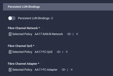
3. Click Add to add the vHBA-B.
4. Verify both the vHBAs are added to the SAN connectivity policy.
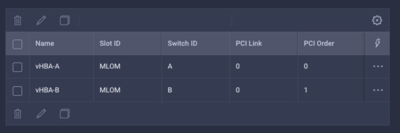
![]() If the customers don’t need the NVMe-o-FC connectivity, skip the next sections for creating NVMe vHBAs.
If the customers don’t need the NVMe-o-FC connectivity, skip the next sections for creating NVMe vHBAs.
Create the NVMe-o-FC vHBA
To configure (optional) NVMe-o-FC, two vHBAs, one for each fabric, need to be added to the server profile template. These vHBAs are in addition to the FC boot from SAN vHBAs, vHBA-A and vHBA-b.
Table 18. vHBA placement for NVMe-o-FC
| vNIC/vHBA Name |
Slot |
Switch ID |
PCI Order |
| vHBA-NVMe-A |
MLOM |
A |
6 |
| vHBA-NVMe-B |
MLOM |
B |
7 |
To add vHBA-NVMe-A for SAN A, follow these steps:
1. Click Add vHBA.
2. For vHBA Type, select fc-nvme-initiator from the drop-down list.
3. Click Select Pool under WWPN Address Pool and then, in the pane on the right, select the previously created pool AA17-WWPN-Pool-A.
4. Provide the Name (for example, vHBA-NVMe-A), Switch ID (for example, A) and PCI Order from Table 18.
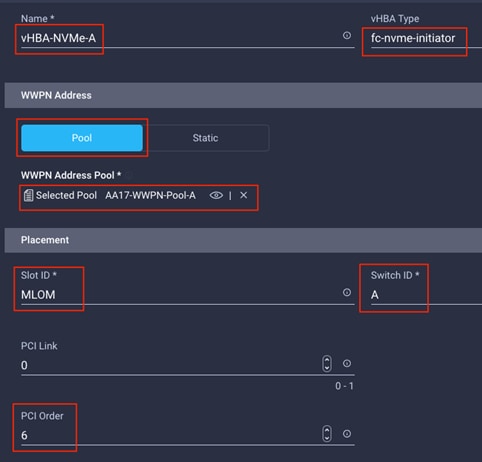
5. Click Select Policy under Fibre Channel Network and then, in the pane on the right, select the previously created policy for SAN A, AA17-SAN-A-Network.
6. Click Select Policy under Fibre Channel QoS and then, in the pane on the right, select the previously created QoS policy AA17-FC-QoS.
7. Click Select Policy under Fibre Channel Adapter and then, in the pane on the right, select the previously created Adapter policy AA17-FC-Adapter.
8. Verify all the vHBA policies are mapped.
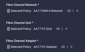
Configure vHBA-NVMe-B
To add vHBA-NVMe-B for SAN B, follow these steps:
1. Click Add vHBA.
2. For vHBA Type, select fc-nvme-initiator from the drop-down list.
3. Click Select Pool under WWPN Address Pool and then, in the pane on the right, select the previously created pool AA17-WWPN-Pool-B.
4. Provide the Name (for example, vHBA-NVMe-B), Switch ID (for example, B) and PCI Order from Table 18.
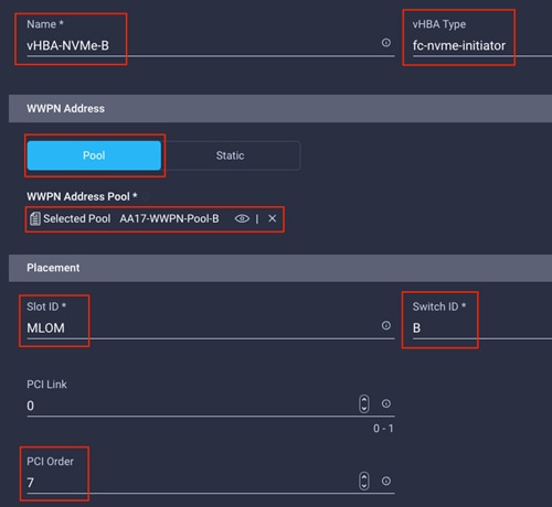
5. Click Select Policy under Fibre Channel Network and then, in the pane on the right, select the previously created policy for SAN B, AA17-SAN-B-Network.
6. Click Select Policy under Fibre Channel QoS and then, in the pane on the right, select the previously created QoS policy AA17-FC-QoS.
7. Click Select Policy under Fibre Channel Adapter and then, in the pane on the right, select the previously created Adapter policy AA17-FC-Adapter.
8. Verify all the vHBA policies are mapped correctly.
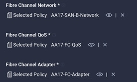
Verify all the vHBAs
To verify the vHBAs, follow these steps:
1. Verify all four vHBAs are added to the SAN connectivity policy.
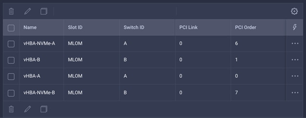
2. Click Create to create the SAN connectivity policy with NVMe-o-FC support.
Step 7: Summary
When the LAN connectivity policy and SAN connectivity policy (for FC) is created, click Next to move to the Summary screen.
On the summary screen, verify policies mapped to various settings. The screenshots below provide summary view for a FC boot from SAN server profile template.
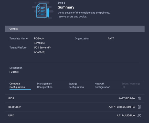
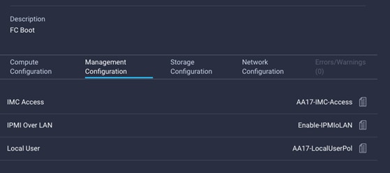
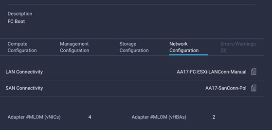
To derive one or many server profiles from the configured template, follow these steps:
1. From the Server profile template Summary screen, click Derive Profiles.
![]() This action can also be performed later by navigating to Templates, clicking “…” next to the template name and selecting Derive Profiles.
This action can also be performed later by navigating to Templates, clicking “…” next to the template name and selecting Derive Profiles.
2. Under the Server Assignment, select Assign Now and select Cisco UCS X210c M6 or Cisco UCS B200 M6 servers. Customers can select one or more servers depending on the number of profiles to be deployed.
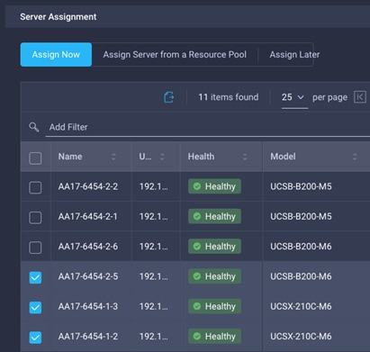
![]() The server profile template and policies in this document apply to both Cisco UCS X210x M6 and Cisco UCS B200 M6 servers.
The server profile template and policies in this document apply to both Cisco UCS X210x M6 and Cisco UCS B200 M6 servers.
3. Click Next.
4. Intersight will fill in default information for the number of servers selected (3 in this case).
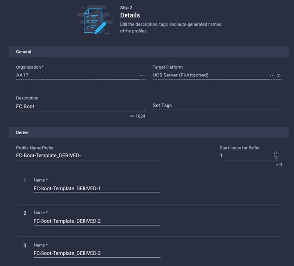
5. Adjust the Prefix and number if needed.
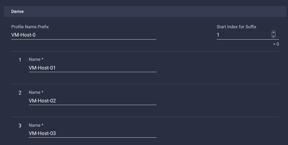
6. Click Next.
7. Verify the information and click Derive to create the Server Profiles.
8. Intersight will start configuring the server profiles and will take some time to apply all the policies. Use the Requests tab to see the progress.
![]()
9. When the Server Profiles are deployed successfully, they will appear under the Server Profiles with the status of OK.
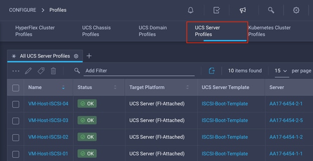
This section explains how to configure the Cisco MDS 9000s for use in a FlexPod environment. The configuration covered in this section is only needed when configuring Fibre Channel and FC-NVMe storage access.
![]() If FC connectivity is not required in the FlexPod deployment, this section can be skipped.
If FC connectivity is not required in the FlexPod deployment, this section can be skipped.
Physical Connectivity
Follow the physical connectivity guidelines for FlexPod as explained in Physical Topology section.
FlexPod Cisco MDS Base
The following procedures describe how to configure the Cisco MDS switches for use in a base FlexPod environment. This procedure assumes you are using the Cisco MDS 9132T with NX-OS 8.4(2c).
Cisco MDS 9132T A and 9132T B
To set up the initial configuration for the Cisco MDS A switch, <mds-A-hostname>, follow these steps:
![]() On initial boot and connection to the serial or console port of the switch, the NX-OS setup should automatically start and attempt to enter Power on Auto Provisioning. Enter y to get to the System Admin Account Setup.
On initial boot and connection to the serial or console port of the switch, the NX-OS setup should automatically start and attempt to enter Power on Auto Provisioning. Enter y to get to the System Admin Account Setup.
1. Configure the switch using the command line.
---- System Admin Account Setup ----
Do you want to enforce secure password standard (yes/no) [y]: Enter
Enter the password for "admin": <password>
Confirm the password for "admin": <password>
Would you like to enter the basic configuration dialog (yes/no): yes
Create another login account (yes/no) [n]: Enter
Configure read-only SNMP community string (yes/no) [n]: Enter
Configure read-write SNMP community string (yes/no) [n]: Enter
Enter the switch name : <mds-A-hostname>
Continue with Out-of-band (mgmt0) management configuration? (yes/no) [y]: Enter
Mgmt0 IPv4 address : <mds-A-mgmt0-ip>
Mgmt0 IPv4 netmask : <mds-A-mgmt0-netmask>
Configure the default gateway? (yes/no) [y]: Enter
IPv4 address of the default gateway : <mds-A-mgmt0-gw>
Configure advanced IP options? (yes/no) [n]: Enter
Enable the ssh service? (yes/no) [y]: Enter
Type of ssh key you would like to generate (dsa/rsa) [rsa]: Enter
Number of rsa key bits <1024-2048> [1024]: Enter
Enable the telnet service? (yes/no) [n]: Enter
Configure congestion/no_credit drop for fc interfaces? (yes/no) [y]: Enter
Enter the type of drop to configure congestion/no_credit drop? (con/no) [c]: Enter
Enter milliseconds in multiples of 10 for congestion-drop for logical-type edge
in range (<200-500>/default), where default is 500. [d]: Enter
Enable the http-server? (yes/no) [y]: Enter
Configure clock? (yes/no) [n]: Enter
Configure timezone? (yes/no) [n]: Enter
Configure summertime? (yes/no) [n]: Enter
Configure the ntp server? (yes/no) [n]: Enter
Configure default switchport interface state (shut/noshut) [shut]: Enter
Configure default switchport trunk mode (on/off/auto) [on]: auto
Configure default switchport port mode F (yes/no) [n]: yes
Configure default zone policy (permit/deny) [deny]: Enter
Enable full zoneset distribution? (yes/no) [n]: Enter
Configure default zone mode (basic/enhanced) [basic]: Enter
2. Review the configuration.
Would you like to edit the configuration? (yes/no) [n]: Enter
Use this configuration and save it? (yes/no) [y]: Enter
To set up the initial configuration of the Cisco MDS B switch, repeat the steps above with appropriate host and IP address information.
Enable Feature
Cisco MDS 9132T A and Cisco MDS 9132T B
To enable the correct features on the Cisco MDS switches, follow these steps:
1. Log in as admin.
2. Run the following commands:
configure terminal
feature npiv
feature fport-channel-trunk
Add NTP Servers and Local Time Configuration
Cisco MDS 9132T A and Cisco MDS 9132T B
To configure the NTP server and add local time configuration, follow this step:
1. From the global configuration mode, run the following command:
ntp server <NTP-Server-1-IP>
ntp server <NTP-Server-2-IP>
clock timezone <timezone> <hour-offset> <minute-offset>
clock summer-time <timezone> <start-week> <start-day> <start-month> <start-time> <end-week> <end-day> <end-month> <end-time> <offset-minutes>
![]() It is important to configure the network time so that logging time alignment, any backup schedules, and SAN Analytics forwarding are correct. For more information on configuring the timezone and daylight savings time or summer time, please see Cisco MDS 9000 Series Fundamentals Configuration Guide, Release 8.x. Sample clock commands for the United States Eastern timezone are:
It is important to configure the network time so that logging time alignment, any backup schedules, and SAN Analytics forwarding are correct. For more information on configuring the timezone and daylight savings time or summer time, please see Cisco MDS 9000 Series Fundamentals Configuration Guide, Release 8.x. Sample clock commands for the United States Eastern timezone are:
clock timezone EST -5 0
clock summer-time EDT 2 Sunday March 02:00 1 Sunday November 02:00 60
Cisco MDS 9132T A
To configure individual ports and port-channels for switch A, follow this step:
1. From the global configuration mode, run the following commands:
switchport description <storage-node-1>:5a
switchport speed 32000
switchport trunk mode off
port-license acquire
no shutdown
!
interface fc1/2
switchport description <storage-node-2>:5a
switchport speed 32000
switchport trunk mode off
port-license acquire
no shutdown
!
interface port-channel1
channel mode active
switchport trunk allowed vsan <vsan-a-id for example, 101>
switchport description <ucs-clustername>-a
switchport speed 32000
no shutdown
!
interface fc1/3
switchport description <ucs-clustername>-a:1/3
channel-group 1
port-license acquire
no shutdown
!
interface fc1/4
switchport description <ucs-clustername>-a:1/4
channel-group 1
port-license acquire
no shutdown
!
Cisco MDS 9132T B
To configure individual ports and port-channels for switch B, follow this step:
1. From the global configuration mode, run the following commands:
interface fc1/1
switchport description <storage-node-1>:5b
switchport speed 32000
switchport trunk mode off
port-license acquire
no shutdown
!
interface fc1/2
switchport description <storage-node-2>:5b
switchport speed 32000
switchport trunk mode off
port-license acquire
no shutdown
!
interface port-channel2
channel mode active
switchport trunk allowed vsan <vsan-b-id for example, 102>
switchport description <ucs-clustername>-b
switchport speed 32000
no shutdown
!
interface fc1/3
switchport description <ucs-clustername>-b:1/3
channel-group 2 force
port-license acquire
no shutdown
!
interface fc1/4
switchport description <ucs-clustername>-b:1/4
channel-group 2 force
port-license acquire
no shutdown
!
![]() If VSAN trunk is not configured between the Cisco UCS Fabric Interconnects and the Cisco MDS switches, do not enter “switchport trunk allowed vsan <vsan-b-id>” for interface port-channel2.
If VSAN trunk is not configured between the Cisco UCS Fabric Interconnects and the Cisco MDS switches, do not enter “switchport trunk allowed vsan <vsan-b-id>” for interface port-channel2.
Cisco MDS 9132T A
To create the necessary VSANs for fabric A and add ports to them, follow this step:
1. From the global configuration mode, run the following commands:
vsan database
vsan <vsan-a-id>
vsan <vsan-a-id> name Fabric-A
exit
zone smart-zoning enable vsan <vsan-a-id>
vsan database
vsan <vsan-a-id> interface fc1/1
vsan <vsan-a-id> interface fc1/2
vsan <vsan-a-id> interface port-channel1
exit
Cisco MDS 9132T B
To create the necessary VSANs for fabric B and add ports to them, follow this step:
1. From the global configuration mode, run the following commands:
vsan database
vsan <vsan-b-id>
vsan <vsan-b-id> name Fabric-B
exit
zone smart-zoning enable vsan <vsan-b-id>
vsan database
vsan <vsan-b-id> interface fc1/1
vsan <vsan-b-id> interface fc1/2
vsan <vsan-b-id> interface port-channel2
exit
Cisco MDS 9132T A
To create the device aliases, follow these steps:
1. The WWPN information required to create device-alias and zones can be gathered from NetApp using the following command:
network interface show -vserver Infra-SVM -data-protocol fcp
2. The WWPN information for a Server Profile can be obtained by logging into Intersight, go to CONFIGURE > Profiles > UCS Server Profile. Click on a Server Profile and then click on the name of SAN Connectivity policy.
To create device aliases for Fabric A that will be used to create zones, follow these steps:
1. From the global configuration mode, run the following commands:
device-alias mode enhanced
device-alias database
device-alias name Infra-SVM-fcp-lif-01a pwwn <fcp-lif-01a-wwpn>
device-alias name Infra-SVM-fcp-lif-02a pwwn <fcp-lif-02a-wwpn>
device-alias name VM-Host-Infra-FCP-01-A pwwn <vm-host-infra-fcp-01-wwpna>
device-alias name VM-Host-Infra-FCP-02-A pwwn <vm-host-infra-fcp-02-wwpna>
device-alias name VM-Host-Infra-FCP-03-A pwwn <vm-host-infra-fcp-03-wwpna>
2. If configuring FC-NVMe, following device alias entries also needs to be defined:
device-alias name Infra-SVM-fc-nvme-lif-01a pwwn <fc-nvme-lif-01a-wwpn>
device-alias name Infra-SVM-fc-nvme-lif-02a pwwn <fc-nvme-lif-02a-wwpn>
device-alias name VM-Host-Infra-FC-NVMe-01-A pwwn <vm-host-infra-fc-nvme-01-wwpna>
device-alias name VM-Host-Infra-FC-NVMe-02-A pwwn <vm-host-infra-fc-nvme-02-wwpna>
device-alias name VM-Host-Infra-FC-NVMe-03-A pwwn <vm-host-infra-fc-nvme-03-wwpna>
3. Commit the device alias database changes:
device-alias commit
Cisco MDS 9132T B
1. The WWPN information required to create device-alias and zones can be gathered from NetApp using the following command:
network interface show -vserver Infra-SVM -data-protocol fcp
2. The WWPN information for a Server Profile can be obtained by logging into Intersight, go to CONFIGURE > Profiles > UCS Server Profile. Click on a Server Profile and then click on the name of SAN Connectivity policy.
To create device aliases for Fabric B that will be used to create zones, follow these steps:
1. From the global configuration mode, run the following commands:
device-alias mode enhanced
device-alias database
device-alias name Infra-SVM-fcp-lif-01b pwwn <fcp-lif-01b-wwpn>
device-alias name Infra-SVM-fcp-lif-02b pwwn <fcp-lif-02b-wwpn>
device-alias name VM-Host-Infra-FCP-01-B pwwn <vm-host-infra-fcp-01-wwpnb>
device-alias name VM-Host-Infra-FCP-02-B pwwn <vm-host-infra-fcp-02-wwpnb>
device-alias name VM-Host-Infra-FCP-03-B pwwn <vm-host-infra-fcp-03-wwpnb>
2. If configuring FC-NVMe, following device alias entries also needs to be defined:
device-alias name Infra-SVM-FC-NVMe-lif-01b pwwn <fc-nvme-lif-01b-wwpn>
device-alias name Infra-SVM-FC-NVMe-lif-02b pwwn <fc-nvme-lif-02b-wwpn>
device-alias name VM-Host-Infra-FC-NVMe-01-B pwwn <vm-host-infra-fc-nvme-01-wwpnb>
device-alias name VM-Host-Infra-FC-NVMe-02-B pwwn <vm-host-infra-fc-nvme-02-wwpnb>
device-alias name VM-Host-Infra-FC-NVMe-03-B pwwn <vm-host-infra-fc-nvme-03-wwpnb>
3. Commit the device alias database changes:
device-alias commit
Cisco MDS 9132T A
1. To create the required zones for FC on Fabric A, run the following commands:
configure terminal
zone name FCP-Infra-SVM-A vsan <vsan-a-id>
member device-alias VM-Host-Infra-FCP-01-A init
member device-alias VM-Host-Infra-FCP-02-A init
member device-alias VM-Host-Infra-FCP-03-A init
member device-alias Infra-SVM-fcp-lif-01a target
member device-alias Infra-SVM-fcp-lif-02a target
exit
2. To create the required zones for FC-NVMe on Fabric A, run the following commands:
zone name FC-NVMe-Infra-SVM-A vsan <vsan-a-id>
member device-alias VM-Host-Infra-FC-NVMe-01-A init
member device-alias VM-Host-Infra-FC-NVMe-02-A init
member device-alias VM-Host-Infra-FC-NVMe-03-A init
member device-alias Infra-SVM-FC-NVMe-lif-01a target
member device-alias Infra-SVM-FC-NVMe-lif-02a target
exit
3. To create the zoneset for the zone(s) defined above, issue the following command:
zoneset name Fabric-A vsan <vsan-a-id>
member FCP-Infra-SVM-A
member FC-NVMe-Infra-SVM-A
exit
4. Activate the zoneset:
zoneset activate name Fabric-A vsan <vsan-a-id>
5. Save the configuration:
copy run start
![]() Since Smart Zoning is enabled, a single zone for each storage protocol (FCP and FC-NVMe) is created with all host initiators and targets for the Infra_SVM instead of creating separate zones for each host. If a new host is added, its initiator can simply be added to appropriate zone in each MDS switch and the zoneset is reactivated.
Since Smart Zoning is enabled, a single zone for each storage protocol (FCP and FC-NVMe) is created with all host initiators and targets for the Infra_SVM instead of creating separate zones for each host. If a new host is added, its initiator can simply be added to appropriate zone in each MDS switch and the zoneset is reactivated.
Cisco MDS 9132T B
1. To create the required zones and zoneset on Fabric B, run the following commands:
configure terminal
zone name FCP-Infra-SVM-B vsan <vsan-b-id>
member device-alias VM-Host-Infra-FCP-01-B init
member device-alias VM-Host-Infra-FCP-02-B init
member device-alias VM-Host-Infra-FCP-03-B init
member device-alias Infra-SVM-fcp-lif-01b target
member device-alias Infra-SVM-fcp-lif-02b target
exit
2. To create the required zones for FC-NVMe on Fabric A, run the following commands:
zone name FC-NVMe-Infra-SVM-B vsan <vsan-b-id>
member device-alias VM-Host-Infra-FC-NVMe-01-B init
member device-alias VM-Host-Infra-FC-NVMe-02-B init
member device-alias VM-Host-Infra-FC-NVMe-03-B init
member device-alias Infra-SVM-FC-NVMe-lif-01b target
member device-alias Infra-SVM-FC-NVMe-lif-02b target
exit
3. To create the zoneset for the zone(s) defined above, issue the following command:
zoneset name Fabric-B vsan <vsan-b-id>
member FCP-Infra-SVM-B
member FC-NVMe-Infra_SVM-B
exit
4. Activate the zoneset:
zoneset activate name Fabric-B vsan <vsan-b-id>
5. Save the configuration:
copy run start
Storage Configuration – ONTAP Boot Storage Setup
This configuration requires information from both the server profiles and NetApp storage system. After creating the boot LUNs, initiator groups and appropriate mappings between the two, UCS server profiles will be able to see the boot disks hosted on NetApp controllers.
Create Boot LUNs
To create boot LUNs for all the ESXi servers, run the following commands on NetApp cluster management console:
lun create -vserver Infra-SVM -path /vol/esxi_boot/VM-Host-Infra-01 -size 32GB -ostype vmware -space-reserve disabled
lun create -vserver Infra-SVM -path /vol/esxi_boot/VM-Host-Infra-02 -size 32GB -ostype vmware -space-reserve disabled
lun create -vserver Infra-SVM -path /vol/esxi_boot/VM-Host-Infra-03 -size 32GB -ostype vmware -space-reserve disabled
Create Initiator Groups
Obtain the WWPNs for NetApp FC LIFs (only for FC configuration)
Run the following commands on NetApp cluster management console:
network interface show -vserver Infra-SVM -data-protocol fcp
Obtain the WWPNs for UCS Server Profiles (only for FC configuration)
From the Intersight GUI, follow: CONFIGURE > Profile. Select UCS Server Profile and click on [Server Profile Name]. Under General, click SAN Connectivity and find the WWPN information for various vHBAs in the window on the right.

Obtain the IQN for NetApp Storage Virtual Machine (only for iSCSI configuration)
Run the following commands on NetApp cluster management console:
iscsi show -vserver Infra-SVM
Obtain the IQNs for UCS Server Profiles (only for iSCSI configuration)
From Intersight, go to: Pools > [IQN Pool Name] > Usage and find the IQN information for various servers:
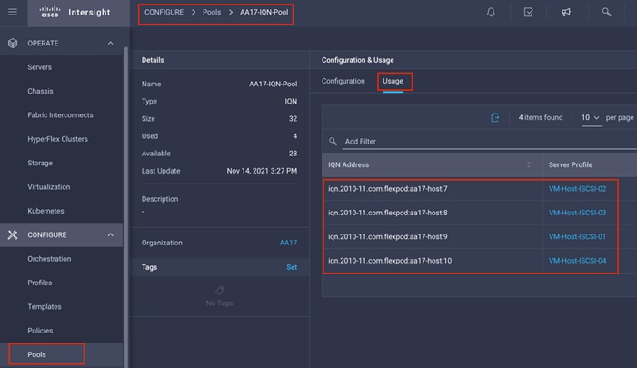
Create Initiator Groups for FC Storage Access
To create initiator groups (igroups) by entering the following commands on NetApp cluster management console:
1. To access boot LUNs, following igroups for individual hosts are created:
lun igroup create –vserver Infra-SVM –igroup VM-Host-FC-01 –protocol fcp –ostype vmware –initiator <vm-host-infra-01-wwpna>, <vm-host-infra-01-wwpnb>
lun igroup create –vserver Infra-SVM –igroup VM-Host-FC-02 –protocol fcp –ostype vmware –initiator <vm-host-infra-02-wwpna>, <vm-host-infra-02-wwpnb>
lun igroup create –vserver Infra-SVM –igroup VM-Host-FC-03 –protocol fcp –ostype vmware –initiator <vm-host-infra-03-wwpna>, <vm-host-infra-03-wwpnb>
2. To view and verify the FC igroups just created, use the following command:
AA17-A400::> lun igroup show -vserver Infra-SVM -protocol fcp
Vserver Igroup Protocol OS Type Initiators
--------- ------------ -------- -------- ------------------------------------
Infra-SVM VM-Host-FC-01
fcp vmware 20:00:00:25:b5:17:0a:00
20:00:00:25:b5:17:0b:00
Infra-SVM VM-Host-FC-02
fcp vmware 20:00:00:25:b5:17:0a:01
20:00:00:25:b5:17:0b:01
Infra-SVM VM-Host-FC-03
fcp vmware 20:00:00:25:b5:17:0a:03
20:00:00:25:b5:17:0b:02
3 entries were displayed.
3. (Optional) To access a common datastore from all the hosts, a common igroup for all the servers can be created as follows:
lun igroup create –vserver Infra-SVM –igroup MGMT-Hosts –protocol fcp –ostype vmware –initiator <vm-host-infra-01-wwpna>, <vm-host-infra-01-wwpnb>, <vm-host-infra-02-wwpna>, <vm-host-infra-02-wwpnb>, <vm-host-infra-03-wwpna>, <vm-host-infra-03-wwpnb>
Create Initiator Groups for iSCSI Storage Access
1. To create initiator groups (igroups) by entering the following commands on NetApp cluster management console:
lun igroup create –vserver <infra-data-svm> –igroup VM-Host-iSCSI-01 –protocol iscsi –ostype vmware –initiator <vm-host-infra-01-iqn>
lun igroup create –vserver <infra-data-svm> –igroup VM-Host-iSCSI-02 –protocol iscsi –ostype vmware –initiator <vm-host-infra-02-iqn>
lun igroup create –vserver <infra-data-svm> –igroup VM-Host-iSCSI-03 –protocol iscsi –ostype vmware –initiator <vm-host-infra-03-iqn>
lun igroup create –vserver <infra-data-svm> –igroup VM-Host-iSCSI-04 –protocol iscsi –ostype vmware –initiator <vm-host-infra-04-iqn>
2. To view and verify the igroups just created, use the following command:
AA17-A400::> lun igroup show -vserver Infra-SVM -protocol iscsi
Vserver Igroup Protocol OS Type Initiators
--------- ------------ -------- -------- ------------------------------------
Infra-SVM VM-Host-iSCSI-01
iscsi vmware iqn.2010-11.com.flexpod:aa17-host:9
Infra-SVM VM-Host-iSCSI-02
iscsi vmware iqn.2010-11.com.flexpod:aa17-host:7
Infra-SVM VM-Host-iSCSI-03
iscsi vmware iqn.2010-11.com.flexpod:aa17-host:8
Infra-SVM VM-Host-iSCSI-04
iscsi vmware iqn.2010-11.com.flexpod:aa17-host:10
4 entries were displayed.
3. (Optional) To access a common datastore from all the hosts, a common igroup for all the servers can be created as follows:
lun igroup create –vserver Infra-SVM –igroup MGMT-Hosts –protocol iscsi –ostype vmware –initiator < vm-host-infra-01-iqn >, < vm-host-infra-02-iqn>, < vm-host-infra-03-iqn>, < vm-host-infra-04-iqn>
Map Boot LUNs to igroups (required only for FC configuration)
1. Map the boot LUNs to FC igroups, by entering the following commands on NetApp cluster management console:
lun mapping create –vserver Infra-SVM –path /vol/esxi_boot/VM-Host-Infra-01 –igroup VM-Host-FC-01 –lun-id 0
lun mapping create –vserver Infra-SVM –path /vol/esxi_boot/VM-Host-Infra-02 –igroup VM-Host-FC-02 –lun-id 0
lun mapping create –vserver Infra-SVM –path /vol/esxi_boot/VM-Host-Infra-03 –igroup VM-Host-FC-03 –lun-id 0
2. To verify the mapping was setup correctly, issue the following command:
lun mapping show -vserver Infra-SVM -protocol fcp
Map Boot LUNs to igroups (required only for iSCSI configuration)
1. Map the boot LUNs to FC igroups, by entering the following commands on NetApp cluster management console:
lun mapping create –vserver <infra-data-svm> –path /vol/esxi_boot/VM-Host-Infra-01 –igroup VM-Host-Infra-01 –lun-id 0
lun mapping create –vserver <infra-data-svm> –path /vol/esxi_boot/VM-Host-Infra-02 –igroup VM-Host-Infra-02 –lun-id 0
lun mapping create –vserver <infra-data-svm> –path /vol/esxi_boot/VM-Host-Infra-03 –igroup VM-Host-Infra-03 –lun-id 0
lun mapping create –vserver <infra-data-svm> –path /vol/esxi_boot/VM-Host-Infra-04 –igroup VM-Host-Infra-04 –lun-id 0
2. To verify the mapping was setup correctly, issue the following command:
lun mapping show -vserver Infra-SVM -protocol iscsi
This section provides detailed instructions for installing VMware ESXi 7.0 in a FlexPod environment. On successful completion of these steps, multiple ESXi hosts will be provisioned and ready to be added to VMware vCenter.
Several methods exist for installing ESXi in a VMware environment. These procedures focus on how to use the built-in keyboard, video, mouse (KVM) console and virtual media features in Cisco UCS Manager to map remote installation media to individual servers.
Download ESXi 7.0U2 from VMware
To download VMware ESXi ISO, follow these steps:
1. Click the following link: Cisco Custom Image for ESXi 7.0 U2 Install ISO.
2. You will need a VMware user id and password on vmware.com to download this software.
3. Download the .iso file.
Log into Cisco Intersight and launch KVM
The Cisco Intersight KVM enables the administrators to begin the installation of the operating system (OS) through remote media. It is necessary to log into the Cisco Intersight to access KVM.
To access server KVM, follow these steps:
1. Log into Cisco Intersight.
2. From the main menu, click Servers.
3. Find the Server and click “…” to see more options
4. Click Launch vKVM.
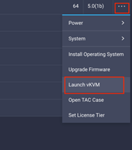
5. Follow the prompts to ignore certificate workings (if any) and launch the HTML5 KVM console.
6. Repeat steps 1 - 5 to launch the HTML5 KVM console for all the servers.
Set Up VMware ESXi Installation
To prepare the server for the OS installation, follow these steps on each ESXi host:
1. In the KVM window, click Virtual Media > vKVM-Mapped vDVD.
2. Browse and select the ESXi installer ISO image file downloaded in the last step.
3. Click Map Drive.
4. Select Macros > Static Macros > Ctrl + Alt + Delete to reboot the Server if the server is showing shell prompt. If the server is shutdown, from Intersight, select “…” next to server and click Power On.
5. Monitor the server boot process in the KVM. Server should find the boot LUNs and begin to load the ESXi installer.
![]() If the ESXi installer fails to load because the software certificates cannot be validated, reset the server, and when prompted, press F2 to go into BIOS and set the system time and date to current. The ESXi installer should load properly.
If the ESXi installer fails to load because the software certificates cannot be validated, reset the server, and when prompted, press F2 to go into BIOS and set the system time and date to current. The ESXi installer should load properly.
To install VMware ESXi onto the bootable LUN of the UCS servers, follow these steps on each host:
1. After the ESXi installer is finished loading (from the last step), press Enter to continue with the installation.
2. Read and accept the end-user license agreement (EULA). Press F11 to accept and continue.
![]() It may be necessary to map function keys as User Defined Macros under the Macros menu in the KVM console.
It may be necessary to map function keys as User Defined Macros under the Macros menu in the KVM console.
3. Choose the NetApp boot LUN that was previously set up as the installation disk for ESXi and press Enter to continue with the installation.
4. Choose the appropriate keyboard layout and press Enter.
5. Enter and confirm the root password and press Enter.
6. The installer issues a warning that the selected disk will be repartitioned. Press F11 to continue with the installation.
7. After the installation is complete, click Virtual Media to unmap the installer ISO. Press Enter to reboot the server.
Set Up Management Networking for ESXi Hosts
Adding a management network for each VMware host is required for managing the host. To configure ESXi host with access to the management network, follow these steps on each ESXi host:
1. After the server has finished rebooting, in the UCS KVM console, press F2 to customize VMware ESXi.
2. Log in as root, enter the password set during installation, and press Enter to log in.
3. Use the down arrow key to choose Troubleshooting Options and press Enter.
4. Choose Enable SSH and press Enter.
5. Press Esc to exit the Troubleshooting Options menu.
6. Select the Configure Management Network option and press Enter.
7. Select Network Adapters and press Enter.
8. Using the spacebar, choose vmnic1 in addition to the pre-selected vmnic0.
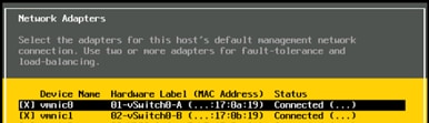
9. Press Enter.
10. Under VLAN (optional) enter the IB-MGMT VLAN and press Enter.
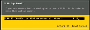
11. Choose IPv4 Configuration and press Enter.
![]() When using DHCP to set the ESXi host networking configuration, setting up a manual IP address is not required.
When using DHCP to set the ESXi host networking configuration, setting up a manual IP address is not required.
12. Choose the Set static IPv4 address and network configuration option by using the arrow keys and space bar.
13. Under IPv4 Address, enter the IP address for managing the ESXi host.
14. Under Subnet Mask, enter the subnet mask.
15. Under Default Gateway, enter the default gateway.
16. Press Enter to accept the changes to the IP configuration.
17. Choose the IPv6 Configuration option and press Enter.
18. Using the spacebar, choose Disable IPv6 (restart required) and press Enter.
19. Choose the DNS Configuration option and press Enter.
![]() If the IP address is configured manually, the DNS information must be provided.
If the IP address is configured manually, the DNS information must be provided.
20. Using the spacebar, choose Use the following DNS server addresses and hostname:
● Under Primary DNS Server, enter the IP address of the primary DNS server.
● Optional: Under Alternate DNS Server, enter the IP address of the secondary DNS server.
● Under Hostname, enter the fully qualified domain name (FQDN) for the ESXi host.
● Press Enter to accept the changes to the DNS configuration.
● Press Esc to exit the Configure Management Network submenu.
● Press Y to confirm the changes and reboot the ESXi host.
(Optional) Reset VMware ESXi Host VMkernel Port MAC Address
By default, the MAC address of the management VMkernel port vmk0 is the same as the MAC address of the Ethernet port it is placed on. If the ESXi host’s boot LUN is remapped to a different server with different MAC addresses, a MAC address conflict will exist because vmk0 will retain the assigned MAC address unless the ESXi System Configuration is reset. To reset the MAC address of vmk0 to a random VMware-assigned MAC address, follow these steps:
1. From the ESXi console menu main screen, type Ctrl-Alt-F1 to access the VMware console command line interface. In the UCSM KVM, Ctrl-Alt-F1 appears in the list of Static Macros.
2. Log in as root.
3. Type “esxcfg-vmknic –l” to get a detailed listing of interface vmk0. vmk0 should be a part of the “Management Network” port group. Note the IP address and netmask of vmk0.
4. To remove vmk0, type esxcfg-vmknic –d “Management Network”.
5. To re-add vmk0 with a random MAC address, type esxcfg-vmknic –a –i <vmk0-ip> -n <vmk0-netmask> “Management Network”.
6. Verify vmk0 has been re-added with a random MAC address by typing esxcfg-vmknic –l.
7. Tag vmk0 as the management interface by typing esxcli network ip interface tag add -i vmk0 -t Management.
8. When vmk0 was re-added, if a message pops up saying vmk1 was marked as the management interface, type esxcli network ip interface tag remove -i vmk1 -t Management.
![]() Steps 9 through 13 are optional steps and only apply to ESXi hosts that support iSCSI boot.
Steps 9 through 13 are optional steps and only apply to ESXi hosts that support iSCSI boot.
9. If this VMware ESXi host is iSCSI booted, the vmk1, iScsiBootPG-A interface’s MAC address can also be reset to a random, VMware-assigned MAC address.
10. Type esxcfg-vmknic –l to get a detailed listing of interface vmk1. vmk1 should be a part of the “iScsiBootPG-A” port group and should have a MAC address from the UCS MAC Pool. Note the IP address and netmask of vmk1.
11. To remove vmk1, type esxcfg-vmknic –d “iScsiBootPG-A.”
12. To re-add vmk1 with a random MAC address, type esxcfg-vmknic –a –i <vmk1-ip> -n <vmk1-netmask> -m 9000 “iScsiBootPG-A.”
13. Verify vmk1 has been re-added with a random MAC address by typing esxcfg-vmknic –l.
Exit the ESXi host configuration:
14. Type exit to log out of the command line interface.
15. Type Ctrl-Alt-F2 to return to the ESXi console menu interface.
Install Cisco VIC Drivers and NetApp NFS Plug-in for VAAI
Download the offline bundle for the Cisco VIC nfnic driver and the NetApp NFS Plug-in for VMware VAAI to the Management workstation:
● Download the ISO Image of UCS related VMware drivers only from: https://software.cisco.com/download/home/286329080/type/283853158/release/5.0(1a). Mount ISO image and follow Storage > Cisco > VIC > ESXi_7.0U2 > nfnic_5.0.0.15 and copy the Cisco-nfnic_5.0.0.15-1OEM.700.1.0.15843807_18697950.zip file.
● NetApp NFS Plug-in for VMware VAAI 2.0 (NetAppNasPluginV2.0.zip) from https://mysupport.netapp.com/site/products/all/details/nfsplugin-vmware-vaai/downloads-tab/download/61278/2.0
![]() Consult the Cisco UCS Hardware Compatibility List and the NetApp Interoperability Matrix Tool to determine latest supported combinations of firmware and software.
Consult the Cisco UCS Hardware Compatibility List and the NetApp Interoperability Matrix Tool to determine latest supported combinations of firmware and software.
To install VMware VIC Drivers and the NetApp NFS Plug-in for VMware VAAI on the ESXi hosts, follow these steps:
1. Using an SCP program, copy the two bundles referenced above to the /tmp directory on each ESXi host.
2. SSH to each VMware ESXi host and log in as root.
3. Run the following commands on each host:
esxcli software component apply -d /tmp/Cisco-nfnic_5.0.0.15-1OEM.700.1.0.15843807_18697950.zip
esxcli software vib install -d /tmp/NetAppNasPluginV2.0.zip
reboot
4. After reboot, SSH back into each host and use the following commands to ensure the correct version are installed:
esxcli software component list | grep nfnic
esxcli software vib list | grep NetApp
FlexPod VMware ESXi Configuration for first ESXi host
To log into the first ESXi host using the VMware Host Client, follow these steps.
1. Open a web browser and navigate to the first ESXi server’s management IP address.
2. Enter root as the User name.
3. Enter the <root password>.
4. Click Log in to connect.
5. Decide whether to join the VMware Customer Experience Improvement Program or not and click OK.
Set Up VMkernel Ports and Virtual Switch
To set up the VMkernel ports and the virtual switches on the first ESXi host, follow these steps:
1. From the Host Client Navigator, choose Networking.
2. In the center pane, choose the Virtual switches tab.
3. Highlight the vSwitch0 line.
4. Click Edit settings.
5. Change the MTU to 9000.
6. Expand NIC teaming.
7. In the Failover order section, choose vmnic1 and click Mark active.
8. Verify that vmnic1 now has a status of Active.
9. Click Save.
10. Choose Networking, then choose the Port groups tab.
11. In the center pane, right-click VM Network and choose Edit settings.
12. Name the port group IB_MGMT. Set the VLAN ID to <IB-MGMT-VLAN> (for example, 17).
![]() (Optional) The IB-MGMT VLAN can be set as the native VLAN for the vSwitch0 vNIC templates and the port group’s VLAN ID can be set to 0.
(Optional) The IB-MGMT VLAN can be set as the native VLAN for the vSwitch0 vNIC templates and the port group’s VLAN ID can be set to 0.
13. Click Save to finalize the edits for the IB-MGMT Network port group.
14. At the top, choose the VMkernel NICs tab.
15. Click Add VMkernel NIC.
16. For New port group, enter VMkernel-Infra-NFS.
17. For Virtual switch, choose vSwitch0.
18. Enter <infra-nfs-vlan-id> (for example, 3017) for the VLAN ID.
19. Change the MTU to 9000.
20. Choose Static IPv4 settings and expand IPv4 settings.
21. Enter the NFS IP address and netmask.
22. Leave TCP/IP stack set at Default TCP/IP stack and do not choose any of the Services.
23. Click Create.
24. Choose the Virtual Switches tab, then vSwitch0. The properties for vSwitch0 should be similar to the following screenshot:
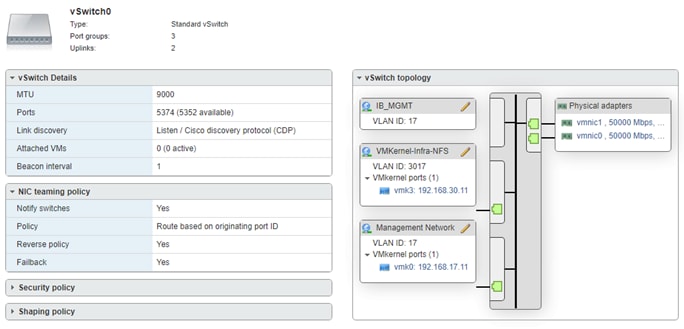
To mount the required datastores, follow these steps on the first ESXi host:
1. From the Web Navigator, choose Storage.
2. In the center pane, choose the Datastores tab.
3. In the center pane, choose New Datastore to add a new datastore.
4. In the New datastore popup, choose Mount NFS datastore and click Next.
5. Enter infra_datastore_1 for the datastore name and IP address of NetApp nfs-lif-01 LIF for the NFS server. Enter /infra_datastore_1 for the NFS share. Select the NFS version. Click Next.
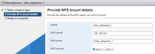
6. Review information and click Finish.
7. The datastore should now appear in the datastore list.
8. In the center pane, choose New Datastore to add a new datastore.
9. In the New datastore popup, choose Mount NFS datastore and click Next.
10. Enter infra_datastore_2 for the datastore name and IP address of NetApp nfs-lif-02 LIF for the NFS server. Enter /infra_datastore_2 for the NFS share. Select the NFS version. Click Next.
11. Click Finish. The datastore should now appear in the datastore list.
12. In the center pane, choose New Datastore to add a new datastore.
13. In the New datastore popup, choose Mount NFS datastore and click Next.
14. Enter infra_swap for the datastore name and IP address of NetApp nfs-lif-01 LIF for the NFS server. Enter /infra_swap for the NFS share. Select the NFS version. Click Next.
15. Click Finish. The datastore should now appear in the datastore list.
Configure NTP Server
To configure Network Time Protocol (NTP) on the first ESXi host, follow these steps:
1. From the Web Navigator, choose Manage.
2. In the center pane, choose System > Time & date.
3. Click Edit NTP Settings.
4. Select Use Network Time Protocol (enable NTP client).
5. Use the drop-down list to choose Start and stop with host.
6. Enter the NTP server IP address(es) in the NTP servers.
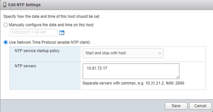
7. Click Save to save the configuration changes.
8. Select the Services tab.
9. Right-click ntpd and choose Start.
10. System > Time & date should now show “Running” for the NTP service status.
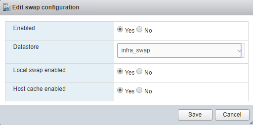
To configure host swap, follow these steps on the first ESXi host:
1. From the Web Navigator, choose Manage.
2. In the center pane, choose System > Swap.
3. Click Edit settings.
4. Use the drop-down list to choose infra_swap. Leave all other settings unchanged.

5. Click Save to save the configuration changes.
To configure the host power policy on the first ESXi host, follow these steps on the host:
![]() Implementation of this policy is recommended in Performance Tuning Guide for Cisco UCS M6 Servers: https://www.cisco.com/c/en/us/products/collateral/servers-unified-computing/ucs-b-series-blade-servers/performance-tuning-guide-ucs-m6-servers.html for maximum VMware ESXi performance. This policy can be adjusted based on customer requirements.
Implementation of this policy is recommended in Performance Tuning Guide for Cisco UCS M6 Servers: https://www.cisco.com/c/en/us/products/collateral/servers-unified-computing/ucs-b-series-blade-servers/performance-tuning-guide-ucs-m6-servers.html for maximum VMware ESXi performance. This policy can be adjusted based on customer requirements.
1. From the Web Navigator, choose Manage.
2. In the center pane, choose Hardware > Power Management.
3. Click Change policy.
4. Select High performance and click OK.
Set Up iSCSI VMkernel Ports and Virtual Switch (required only for iSCSI configuration)
This configuration section only applies to iSCSI ESXi hosts. To setup VMkernel ports and virtual switches on ESXi hosts on VM-Host-Infra-01, follow these steps:
1. From the Web Navigator, click Networking.
2. In the center pane, choose the Virtual switches tab.
3. Highlight the iScsiBootvSwitch line.
4. Click Edit settings.
6. Click Save to save the changes to iScsiBootvSwitch.
7. Choose Add standard virtual switch.
8. Name the switch vSwitch1.
9. Change the MTU to 9000.
10. From the drop-down list select vmnic5 for Uplink 1.
11. Choose Add to add vSwitch1.
12. In the center pane, choose the VMkernel NICs tab.
13. Highlight the iScsiBootPG line.
14. Click Edit settings.
15. Change the MTU to 9000.
16. Expand IPv4 Settings and enter a unique IP address in the Infra-iSCSI-A subnet but outside of the Cisco UCS iSCSI-IP-Pool-A.
![]() It is recommended to enter a unique IP address for this VMkernel port to avoid any issues related to IP Pool reassignments in Cisco UCS.
It is recommended to enter a unique IP address for this VMkernel port to avoid any issues related to IP Pool reassignments in Cisco UCS.
17. Click Save to save the changes to iScsiBootPG VMkernel NIC.
18. Choose Add VMkernel NIC.
19. For New port group, enter iScsiBootPG-B.
20. For Virtual switch, from the drop-down list choose vSwitch1.
21. Change the MTU to 9000.
22. For IPv4 settings, select Static.
23. Expand IPv4 Settings and enter a unique IP address in the Infra-iSCSI-B subnet but outside of the Cisco UCS iSCSI-IP-Pool-B.
24. Click Create to complete creating the VMkernel NIC.
25. In the center pane, choose the Port groups tab.
26. Highlight the iScsiBootPG line.
27. Click Edit settings.
28. Change the Name to iScsiBootPG-A.
29. Click Save to complete editing the port group name.
30. On the left choose Storage, then in the center pane choose the Adapters tab.
31. Select vmhba64 Software iSCSI to configure software iSCSI for the host and click Configure iSCSI.
32. In the Configure iSCSI window, under Dynamic targets, click Add dynamic target.
33. Choose Click to add address and enter the IP address of iscsi-lif-01a from Infra-SVM. Press Enter.
34. Repeat steps 32-33 to add the IP addresses for iscsi-lif-02a, iscsi-lif-01b, and iscsi-lif-02b.
35. Click Save configuration.
36. Click Configure iSCSI again open configuration window for iSCSI software adapter.
37. Verify that four static targets and four dynamic targets are listed for the host.
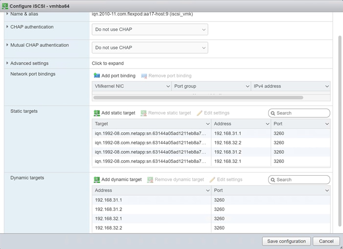
38. Click Cancel to close the window.
VMware vCenter 7.0U2c
The procedures in the following subsections provide detailed instructions for installing the VMware vCenter 7.0U2c Server Appliance in a FlexPod environment.
Download vCenter 7.0U2c from VMware
To download vCenter 7.0U2c, follow these steps:
1. Click the following link: https://customerconnect.vmware.com/downloads/details?downloadGroup=VC70U2C&productId=974&rPId=78220 and download the VMware-VCSA-all-7.0.2-18356314.iso.
2. You will need a VMware user id and password on vmware.com to download this software.
Install the VMware vCenter Server Appliance
The VCSA deployment consists of 2 stages: installation and configuration. To install the VMware vCenter virtual machine, follow these steps:
1. Locate and copy the VMware-VCSA-all-7.0.2-18356314.iso file to the desktop of the management workstation. This ISO is for the VMware vSphere 7.0 U2 vCenter Server Appliance.
2. Mount the ISO image as a disk on the management workstation. (For example, with the Mount command in Windows Server 2012 and above).
3. In the mounted disk directory, navigate to the vcsa-ui-installer > win32 directory and double-click installer.exe. The vCenter Server Appliance Installer wizard appears.
4. Click Install to start the vCenter Server Appliance deployment wizard.
5. Click NEXT in the Introduction section.
6. Read and accept the license agreement and click NEXT.
7. In the “vCenter Server deployment target” window, enter the FQDN or IP address of the destination host, User name (root) and Password. Click NEXT.
![]() Installation of vCenter on a separate existing management infrastructure is recommended. If a separate management infrastructure is not available, customers can choose the recently configured first ESXi host as an installation target.
Installation of vCenter on a separate existing management infrastructure is recommended. If a separate management infrastructure is not available, customers can choose the recently configured first ESXi host as an installation target.
8. Click YES to accept the certificate.
9. Enter the Appliance VM name and password details shown in the “Set up vCenter Server VM” section. Click NEXT.
10. In the “Select deployment size” section, choose the Deployment size and Storage size. For example, choose “Small” and “Default.” Click NEXT.
11. Select the datastore (for example, infra_datastore_02) for storage. Click NEXT.
12. In the Network Settings section, configure the following settings:
a. Select a Network: IB-MGMT Network
![]() It is important that the vCenter VM stay on the IB-MGMT Network on vSwitch0 and not moved to a vDS. If vCenter is moved to a vDS and the virtual environment is completely shut down and then brought back up, trying to bring up vCenter on a different host than the one it was running on before the shutdown, will cause problems with the network connectivity. With the vDS, for a virtual machine to move from one host to another, vCenter must be up and running to coordinate the move of the virtual ports on the vDS. If vCenter is down, the port move on the vDS cannot occur correctly. Moving vCenter to a different host on vSwitch0 does not require vCenter to already be up and running.
It is important that the vCenter VM stay on the IB-MGMT Network on vSwitch0 and not moved to a vDS. If vCenter is moved to a vDS and the virtual environment is completely shut down and then brought back up, trying to bring up vCenter on a different host than the one it was running on before the shutdown, will cause problems with the network connectivity. With the vDS, for a virtual machine to move from one host to another, vCenter must be up and running to coordinate the move of the virtual ports on the vDS. If vCenter is down, the port move on the vDS cannot occur correctly. Moving vCenter to a different host on vSwitch0 does not require vCenter to already be up and running.
b. IP version: IPV4
c. IP assignment: static
d. FQDN: <vcenter-fqdn>
e. IP address: <vcenter-ip>
f. Subnet mask or prefix length: <vcenter-subnet-mask>
g. Default gateway: <vcenter-gateway>
h. DNS Servers: <dns-server1>,<dns-server2>
13. Click NEXT.
14. Review all values and click FINISH to complete the installation.
![]() The vCenter Server appliance installation will take a few minutes to complete.
The vCenter Server appliance installation will take a few minutes to complete.
15. When Stage 1, Deploy vCenter Server, is complete, Click CONTINUE to proceed with stage 2.
16. Click NEXT.
17. In the vCenter Server configuration window, configure these settings:
a. Time Synchronization Mode: Synchronize time with NTP servers.
b. NTP Servers: NTP server IP addresses.
c. SSH access: Enabled.
18. Click NEXT.
19. Complete the SSO configuration as shown below (or according to your organization’s security policies):
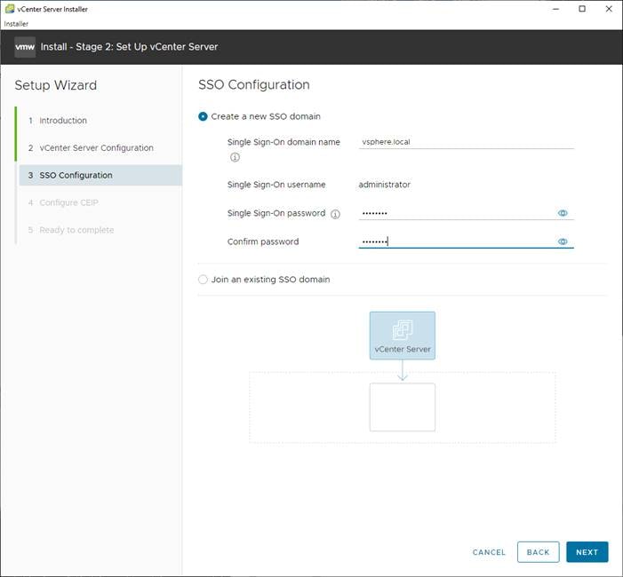
20. Click NEXT.
21. Decide whether to join VMware’s Customer Experience Improvement Program (CEIP).
22. Click NEXT.
23. Review the configuration and click FINISH.
24. Click OK.
![]() vCenter Server setup will take a few minutes to complete and Install – Stage 2 with show Complete
vCenter Server setup will take a few minutes to complete and Install – Stage 2 with show Complete
25. Click CLOSE. Eject or unmount the VCSA installer ISO.
If a vCenter deployment size of Small or larger was selected in the vCenter setup, it is possible that the VCSA’s CPU setup does not match the Cisco UCS server CPU hardware configuration. Cisco UCS X210c M6 and B200 M6 servers are 2-socket servers. During this validation, the Small deployment size was selected and vCenter was setup for a 4-socket server. This setup can cause issues in the VMware ESXi cluster Admission Control. To resolve the Admission Control issue, follow these steps:
1. Open a web browser on the management workstation and navigate to vCenter or ESXi server where vCenter appliance was deployed and login.
2. Click the vCenter VM, right-click and choose Edit settings.
3. In the Edit settings window, expand CPU and check the value of Sockets.
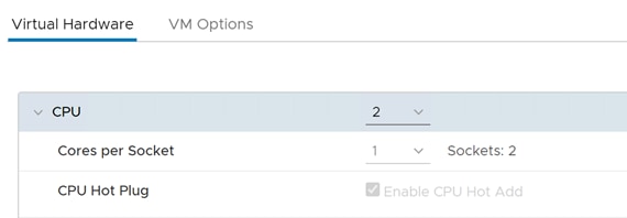
4. If the number of Sockets match the server configuration, click Cancel.
5. If the number of Sockets does not match the server configuration, it will need to be adjusted:
6. Right-click the vCenter VM and choose Guest OS > Shut down. Click Yes on the confirmation.
7. When vCenter is shut down, right-click the vCenter VM and choose Edit settings.
8. In the Edit settings window, expand CPU and change the Cores per Socket value to make the Sockets value equal to the server configuration.
9. Click Save.
10. Right-click the vCenter VM and choose Power > Power on. Wait approximately 10 minutes for vCenter to come up.
To setup the VMware vCenter Server, follow these steps:
1. Using a web browser, navigate to https://<vcenter-ip-address>:5480. Navigate security screens.
2. Log into the VMware vCenter Server Management interface as root with the root password set in the vCenter installation.
3. In the menu on the left, choose Time.
4. Choose EDIT to the right of Time zone.
5. Select the appropriate Time zone and click SAVE.
6. In the menu on the left select Administration.
7. According to your Security Policy, adjust the settings for the root user and password.
8. In the menu on the left choose Update.
9. Follow the prompts to stage and install any available vCenter updates.
10. In the upper right-hand corner of the screen, choose root > Logout to logout of the Appliance Management interface.
11. Using a web browser, navigate to https://<vcenter-ip-address> and navigate through security screens.
![]() With VMware vCenter 7.0 and above, the use of the vCenter FQDN is required.
With VMware vCenter 7.0 and above, the use of the vCenter FQDN is required.
12. Choose LAUNCH VSPHERE CLIENT (HTML5).
![]() The VMware vSphere HTML5 Client is the only option in vSphere 7. All the old clients have been deprecated.
The VMware vSphere HTML5 Client is the only option in vSphere 7. All the old clients have been deprecated.
13. Log in using the Single Sign-On username (administrator@vsphere.local) and password created during the vCenter installation. Dismiss the Licensing warning.
Add AD User Authentication to vCenter (Optional)
To add an AD user authentication to the vCenter, follow these steps:
1. In the AD Infrastructure, using the Active Directory Users and Computers tool, setup a Domain Administrator user with a user name such as flexadmin (FlexPod Admin).
2. Connect to https://<vcenter-ip> and choose LAUNCH VSPHERE CLIENT (HTML5).
3. Log in as Administrator@vsphere.local (or the SSO user set up in vCenter installation) with the corresponding password.
4. Under Menu, choose Administration. In the list on the left, under Single Sign On, choose Configuration.
5. In the center pane, under Configuration, choose the Identity Provider tab.
6. In the list under Type, select Active Directory Domain.
7. Choose JOIN AD.
8. Fill in the AD domain name, the Administrator user, and the domain Administrator password. Do not fill in an Organizational unit. Click JOIN.
9. Click Acknowledge.
10. In the list on the left under Deployment, choose System Configuration. Choose the radio button to choose the vCenter, then choose REBOOT NODE.
11. Input a reboot reason and click REBOOT. The reboot will take approximately 10 minutes for full vCenter initialization.
12. Log back into the vCenter vSphere HTML5 Client as Administrator@vsphere.local.
13. Under Menu, choose Administration. In the list on the left, under Single Sign On, choose Configuration.
14. In the center pane, under Configuration, choose the Identity Provider tab. Under Type, select Identity Sources. Click ADD.
15. Make sure Active Directory (Integrated Windows Authentication) is selected, your Windows Domain name is listed and Use machine account is selected. Click ADD.
16. In the list select the Active Directory (Integrated Windows Authentication) Identity source type. If desired, select SET AS DEFAULT and click OK.
17. On the left under Access Control, select Global Permissions.
18. In the center pane, click the + sign to add a Global Permission.
19. In the Add Permission window, choose your AD domain for the Domain.
20. On the User/Group line, enter either the FlexPod Admin username or the Domain Admins group. Leave the Role set to Administrator. Check the box for Propagate to children.
![]() The FlexPod Admin user was created in the Domain Admins group. The selection here depends on whether the FlexPod Admin user will be the only user used in this FlexPod If additional users will be added later. By selecting the Domain Admins group, any user placed in that AD Domain group will be able to login to vCenter as an Administrator.
The FlexPod Admin user was created in the Domain Admins group. The selection here depends on whether the FlexPod Admin user will be the only user used in this FlexPod If additional users will be added later. By selecting the Domain Admins group, any user placed in that AD Domain group will be able to login to vCenter as an Administrator.
21. Click OK to add the selected User or Group. The user or group should now appear in the Global Permissions list with the Administrator role.
22. Log out and log back into the vCenter HTML5 Client as the FlexPod Admin user. You will need to add the domain name to the user, for example, flexadmin@domain.
vCenter - Initial Configuration
1. In the center pane, choose ACTIONS > New Datacenter.
2. Type FlexPod-DC in the Datacenter name field.
3. Click OK.
4. Expand the vCenter.
5. Right-click the datacenter FlexPod-DC in the list in the left pane. Choose New Cluster…
6. Provide a name for the cluster (for example, AA17-Cluster).
7. Turn on DRS and vSphere HA. Do not turn on vSAN.
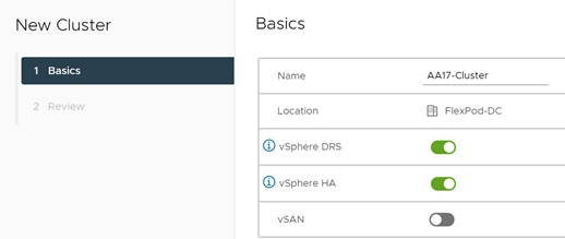
8. Click NEXT and then click FINISH to create the new cluster.
9. Right-click the cluster and choose Settings.
10. Choose Configuration > General in the list located and click EDIT.
11. Choose Datastore specified by host for the Swap file location and click OK.
12. Right-click the cluster and select Add Hosts.
13. In the IP address or FQDN field, enter either the IP address or the FQDN of the first VMware ESXi host. Enter root as the Username and the root password. Click NEXT.
14. In the Security Alert window, choose the host and click OK.
15. Verify the Host summary information and click NEXT.
16. Ignore warnings about the host being moved to Maintenance Mode and click FINISH to complete adding the host to the cluster.
![]() The added ESXi host will have Warnings that the ESXi Shell and SSH have been enabled. These warnings can be suppressed. The host will also have a TPM Encryption Key Recovery alert that can be reset to green.
The added ESXi host will have Warnings that the ESXi Shell and SSH have been enabled. These warnings can be suppressed. The host will also have a TPM Encryption Key Recovery alert that can be reset to green.
17. In the list, right-click the added ESXi host and choose Settings.
18. In the center pane under Virtual Machines, choose Swap File location.
19. On the right, click EDIT.
20. Because of a known issue with the vCenter UI, you will need to use the TAB key to move the cursor to the first datastore in the datastore list. Then use the arrow keys to move the highlight to the infra_swap datastore. Once the infra_swap datastore is highlighted, use the spacebar to select it and click OK.

21. In the center pane under Storage, click Storage Devices. Make sure the NETAPP Fibre Channel Disk LUN 0 or NETAPP iSCSI Disk LUN 0 is selected.
22. Choose the Paths tab.
23. Ensure that 4 paths appear, two of which should have the status Active (I/O). The output below shows the paths for an iSCSI LUN.
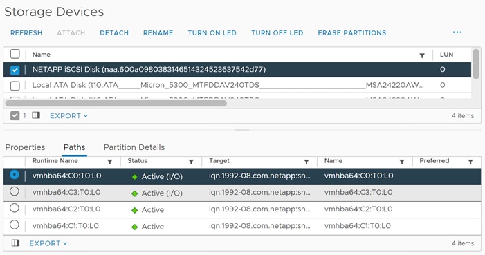
FlexPod VMware vSphere Distributed Switch (vDS
This section provides detailed procedures for setting up VMware vDS in vCenter. Based on the VLAN configuration in Intersight, a vMotion, and a VM-Traffic port group will be added to the vDS. Any additional VLAN-based port groups added to the vDS would require changes in Intersight and the Cisco Nexus 9K switches.
In this document, the infrastructure ESXi management VMkernel ports, the In-Band management interfaces including the vCenter management interface, and the infrastructure NFS VMkernel ports are left on vSwitch0 to facilitate bringing the virtual environment back up in the event it needs to be completely shut down. The vMotion VMkernel ports are moved to the vDS to allow for future QoS support. The vMotion port group is also pinned to Cisco UCS fabric B and pinning configuration in vDS ensures consistency across all ESXi hosts.
Configure the VMware vDS in vCenter
To configure the vDS, follow these steps:
1. After logging into the VMware vSphere HTML5 Client, choose Networking under Menu.
2. Right-click the FlexPod-DC datacenter and choose Distributed Switch > New Distributed Switch.
3. Give the Distributed Switch a descriptive name (for example, AA17_App_DVS) and click NEXT.
4. Make sure version 7.0.2 – ESXi 7.0.2 and later is selected and click NEXT.
5. Change the Number of uplinks to 2. If VMware Network I/O Control is to be used for Quality of Service, leave Network I/O Control Enabled. Otherwise, Disable Network I/O Control. Enter VM-Traffic for the Port group name. Click NEXT.
6. Review the information and click FINISH to complete creating the vDS.
7. Expand the FlexPod-DC datacenter and the newly created vDS. Click the newly created vDS.
8. Right-click the VM-Traffic port group and click Edit Settings.
9. Choose VLAN.
10. Choose VLAN for VLAN type and enter the VM-Traffic VLAN ID (for example, 172). Click OK.
11. Right-click the vDS and choose Settings > Edit Settings.
12. In the Edit Settings window, choose the Advanced tab.
13. Change the MTU to 9000. The Discovery Protocol can optionally be changed to Link Layer Discovery Protocol and the Operation to Both. Click OK.
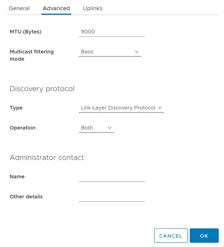
14. To create the vMotion port group, right-click the vDS, select Distributed Port Group > New Distributed Port Group.
15. Enter VMKernel-vMotion as the name and click NEXT.
16. Set the VLAN type to VLAN, enter the VLAN ID used for vMotion (for example, 3317), check the box for Customize default policies configuration, and click NEXT.
17. Leave the Security options set to Reject and click NEXT.
18. Leave the Ingress and Egress traffic shaping options as Disabled and click NEXT.
19. Select Uplink 1 from the list of Active uplinks and click MOVE DOWN twice to place Uplink 1 in the list of Standby uplinks. This will pin all vMotion traffic to UCS Fabric Interconnect B except when a failure occurs.
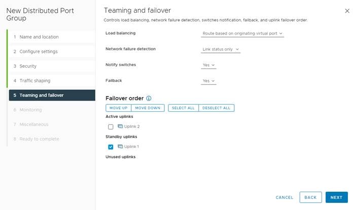
20. Click NEXT.
21. Leave NetFlow disabled and click NEXT.
22. Leave Block all ports set as No and click NEXT.
23. Confirm the options and click FINISH to create the port group.
24. Right-click the vDS and choose Add and Manage Hosts.
25. Make sure Add hosts is selected and click NEXT.
26. Click the green + sign to add new hosts. Choose the first ESXi host and click OK. Click NEXT.
27. Select vmnic2 and click Assign uplink. Choose Uplink 1 and click OK.
28. Select vmnic3 and click Assign uplink. Choose Uplink 2 and click OK.
![]() It is important to assign the uplinks as shown below. This allows the port groups to be pinned to the appropriate Cisco UCS fabric.
It is important to assign the uplinks as shown below. This allows the port groups to be pinned to the appropriate Cisco UCS fabric.
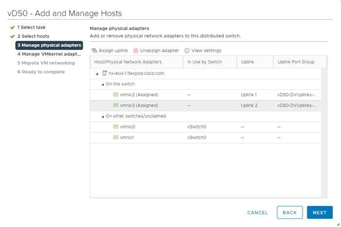
29. Click NEXT.
30. Do not migrate any VMkernel ports and click NEXT.
31. Do not migrate any virtual machine networking ports. Click NEXT.
32. Click FINISH to complete adding the ESXi host to the vDS.
33. Select Hosts and Clusters under Menu and select the first ESXi host. In the center pane, select the Configure tab.
34. In the list under Networking, select VMkernel adapters.
35. Select ADD NETWORKING.
36. In the Add Networking window, ensure that VMkernel Network Adapter is selected and click NEXT.
37. Ensure that Select an existing network is selected and click BROWSE.
38. Select VMKernel-vMotion and click OK.
39. Click NEXT.
40. From the MTU drop-down list, select Custom and ensure the MTU is set to 9000.
41. From the TCP/IP stack drop-down list, select vMotion. Click NEXT.
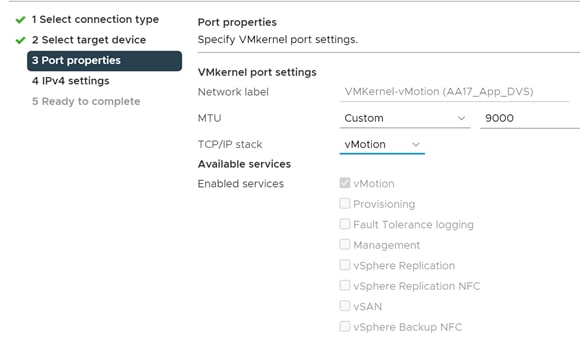
42. Select Use static IPv4 settings and fill in the IPv4 address and Subnet mask for the first ESXi host’s vMotion IP address. Click NEXT.
43. Review the information and click FINISH to complete adding the vMotion VMkernel port.
Add and Configure VMware ESXi Hosts in vCenter
This section details the steps to add and configure an ESXi host in vCenter.
To add the ESXi host(s) to vCenter, follow these steps:
1. From the Home screen in the VMware vCenter HTML5 Interface, choose Menu > Hosts and Clusters.
2. Right-click the cluster and click Add Hosts.
3. In the IP address or FQDN field, enter either the IP address or the FQDN name of the configured VMware ESXi host. Also enter the user id (root) and associated password. If more than one host is being added, add the corresponding host information, optionally selecting “Use the same credentials for all hosts.” Click NEXT.
4. Choose all hosts being added and click OK to accept the thumbprint(s).
5. Review the host details and click NEXT to continue.
6. Review the configuration parameters and click FINISH to add the host(s).
![]() The added ESXi host(s) will be placed in Maintenance Mode and will have Warnings that the ESXi Shell and SSH have been enabled. These warnings can be suppressed. The TPM Encryption Recovery Key Backup Alarm can also be Reset to Green.
The added ESXi host(s) will be placed in Maintenance Mode and will have Warnings that the ESXi Shell and SSH have been enabled. These warnings can be suppressed. The TPM Encryption Recovery Key Backup Alarm can also be Reset to Green.
Set Up VMkernel Ports and Virtual Switch
To set up the VMkernel ports and the virtual switches on the ESXi host, follow these steps:
1. In the vCenter HTML5 Interface, under Hosts and Clusters choose the ESXi host.
2. In the center pane, choose the Configure tab.
3. In the list, choose Virtual switches under Networking.
4. Expand Standard Switch: vSwitch0.
5. Choose EDIT to Edit settings.
6. Change the MTU to 9000.
7. Choose Teaming and failover located on the left.
8. In the Failover order section, use the arrow icons to move the vmnics until both are Active adapters.
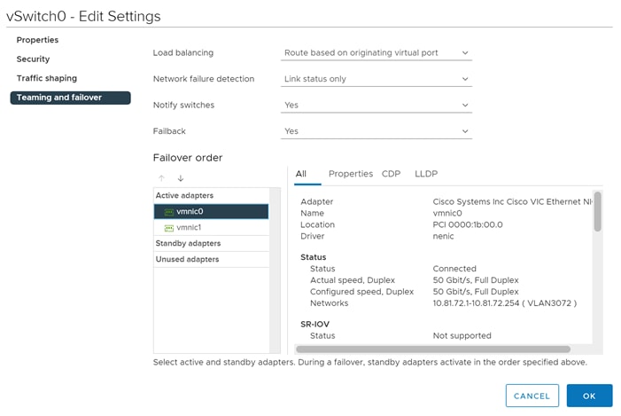
9. Click OK.
10. In the center pane, to the right of VM Network click “…” > Remove to remove the port group. Click YES on the confirmation.
11. Click ADD NETWORKING to add a new VM port group.
12. Select Virtual Machine Port Group for a Standard Switch and click NEXT.
13. Ensure vSwitch0 is shown for Select an existing standard switch and click NEXT.
14. Name the port group “IB_MGMT” and set the VLAN to IB-MGMT-VLAN (for example, 17). Click NEXT.
![]() (Optional) The IB-MGMT VLAN can be set as the native VLAN for the vSwitch0 vNIC templates on Cisco Intersight. The port group’s VLAN ID can then be set to 0.
(Optional) The IB-MGMT VLAN can be set as the native VLAN for the vSwitch0 vNIC templates on Cisco Intersight. The port group’s VLAN ID can then be set to 0.
15. Click FINISH to complete adding the IB_MGMT VM port group.
16. Under Networking, choose VMkernel adapters.
17. In the center pane, click Add Networking.
18. Make sure VMkernel Network Adapter is selected and click NEXT.
19. Choose Select an existing standard switch and click BROWSE. Choose vSwitch0 and click OK. Click NEXT.
20. For Network label, enter VMkernel-Infra-NFS.
21. Enter <infra-nfs-vlan-id for example, 3017> for the VLAN ID.
22. Choose Custom for MTU and set the value to 9000.
23. Leave the Default TCP/IP stack selected and do not choose any of the Enabled services. Click NEXT.
24. Select Use static IPv4 settings and enter the IPv4 address and subnet mask for the Infra-NFS VMkernel port for this ESXi host.
25. Click NEXT.
26. Review the settings and click FINISH to create the VMkernel port.
27. To verify the vSwitch0 setting, under Networking, choose Virtual switches, then expand vSwitch0. The properties for vSwitch0 should be similar to:
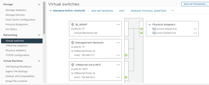
28. Repeat steps 1 – 27 for all the ESXi hosts being added.
To mount the required datastores, follow these steps on the ESXi host(s):
1. From the vCenter Home screen, choose Menu > Storage.
2. Expand FlexPod-DC.
3. Right-click infra_datastore_1 and select Mount Datastore to Additional Hosts.
4. Choose all the ESXi host(s) and click OK.
5. Repeat steps 1 – 4 to mount the infra_datastore_2 and infra_swap datastores on all the ESXi host(s).
6. Select infra_datastore_1 and in the center pane, click Hosts. Verify that all the ESXi host(s) are listed. Repeat this process to verify that both infra_datastore_2 and infra_swap datastores are also mounted on all hosts.
To configure Network Time Protocol (NTP) on the ESXi host(s), follow these steps:
1. In the vCenter HTML5 Interface, under Hosts and Clusters select the ESXi host.
2. In the center pane, select the Configure tab.
3. In the list under System, choose Time Configuration.
4. Click EDIT next to Network Time Protocol.
5. Check the box for Enable.
6. Enter the NTP Server IP address(es) in the NTP servers box separated by a comma.
7. Check the box for Start NTP Service.
8. Use the drop-down list to select Start and stop with host.
9. Click OK to save the configuration changes.
10. Verify that NTP service is now enabled and running, and the clock is now set to correct time.
11. Repeat these steps for all the ESXi hosts.
Change ESXi Power Management Policy
To change the ESXi power management policy, follow these steps:
![]() Implementation of this policy is recommended in Performance Tuning Guide for Cisco UCS M6 Servers: https://www.cisco.com/c/en/us/products/collateral/servers-unified-computing/ucs-b-series-blade-servers/performance-tuning-guide-ucs-m6-servers.html for maximum VMware ESXi performance. This policy can be adjusted based on customer requirements.
Implementation of this policy is recommended in Performance Tuning Guide for Cisco UCS M6 Servers: https://www.cisco.com/c/en/us/products/collateral/servers-unified-computing/ucs-b-series-blade-servers/performance-tuning-guide-ucs-m6-servers.html for maximum VMware ESXi performance. This policy can be adjusted based on customer requirements.
1. In the vCenter HTML5 Interface, under Hosts and Clusters select the ESXi host.
2. In the center pane, select the Configure tab.
3. Under Hardware, choose Overview. Scroll to the bottom and next to Power Management, choose EDIT POWER POLICY.
4. Select High performance and click OK.
Add the ESXi Host(s) to the VMware Virtual Distributed Switch
To add the ESXi host(s) to the VMware vDS, follow these steps:
1. From the VMware vSphere HTML5 Client, choose Networking under Menu.
2. Right-click the vDS and select Add and Manage Hosts.
3. Ensure that Add hosts is selected and click NEXT.
4. Click the green + sign to add New hosts. Choose the ESXi host(s) and click OK. Click NEXT.
5. Choose vmnic2 on each host and click Assign uplink. Select Uplink 1 and click OK.
6. Select vmnic3 on each host and click Assign uplink. Select Uplink 2 and click OK.
7. If more than one host is being connected to the vDS, check the box for Apply this uplink assignment to the rest of the hosts.
![]() It is important to assign the uplinks as defined in these steps. This allows the port groups to be pinned to the appropriate Cisco UCS fabric.
It is important to assign the uplinks as defined in these steps. This allows the port groups to be pinned to the appropriate Cisco UCS fabric.
8. Click NEXT.
9. Do not migrate any VMkernel ports and click NEXT.
10. Do not migrate any VM ports and click NEXT.
11. Click FINISH to complete adding the ESXi host(s) to the vDS.
Add the vMotion VMkernel Port(s) to the ESXi Host
To add the vMotion VMkernel Port to the ESXi host(s), follow these steps on the host:
1. In the vCenter HTML5 Interface, under Hosts and Clusters select the ESXi host.
2. Click the Configure tab.
3. In the list under Networking, choose VMkernel adapters.
4. Select Add Networking to add host networking.
5. Make sure VMkernel Network Adapter is selected and click NEXT.
6. Select BROWSE to the right of Select an existing network.
7. Select VMKernel-vMotion on the vDS and click OK.
8. Click NEXT.
9. Make sure the Network label is VMkernel-vMotion with the vDS in parenthesis. From the drop-down list, select Custom for MTU and make sure the MTU is set to 9000. Select the vMotion TCP/IP stack and click NEXT.
10. Select Use static IPv4 settings and input the host’s vMotion IPv4 address and Subnet mask.
11. Click NEXT.
12. Review the parameters and click FINISH to add the vMotion VMkernel port.
Add iSCSI Configuration (required only for iSCSI configuration)
This section only applies to ESXi host that require iSCSI connectivity. To add an iSCSI configuration to ESXi hosts, follow these steps:
1. In the vSphere HTML5 Client, under Hosts and Clusters, select the ESXi host.
2. In the center pane, click Configure. In the list under Networking, select Virtual switches.
3. In the center pane, expand iScsiBootvSwitch. Click EDIT to edit settings for the vSwitch.
4. Change the MTU to 9000 and click OK.
5. Choose “…” > Edit Settings to the right of iScsiBootPG. Change the Network label to iScsiBootPG-A and click OK.
6. Choose “…” > Edit Settings to the right of the VMkernel Port IP address. Change the MTU to 9000.
7. Click IPv4 settings on the left. Change the IP address to a unique IP address in the Infra-iSCSI-A subnet but outside of the Cisco UCS iSCSI-IP-Pool-A.
![]() It is recommended to enter a unique IP address for this VMkernel port to avoid any issues related to IP Pool reassignments.
It is recommended to enter a unique IP address for this VMkernel port to avoid any issues related to IP Pool reassignments.
8. Click OK.
9. In the upper right-hand corner, choose ADD NETWORKING to add another vSwitch.
10. Make sure VMkernel Network Adapter is selected and click NEXT.
11. Choose New standard vswitch and change the MTU to 9000. Click NEXT.
12. Choose + to add an adapter. Make sure vmnic5 is highlighted and click OK.
13. vmnic5 should now be under Active adapters. Click NEXT.
14. Enter iScsiBootPG-B for the Network label, leave VLAN ID set to None (0), select Custom and set 9000 for MTU. Click NEXT.
15. Select Use static IPv4 settings. Enter a unique IP address and netmask in the Infra-iSCSI-B subnet but outside of the Cisco UCS iSCSI-IP-Pool-B. Click NEXT.
16. Click FINISH to complete creating the vSwitch and the VMkernel port.
17. In the list under Storage, choose Storage Adapters.
18. Select the iSCSI Software Adapter and in the window below, choose the Dynamic Discovery tab.
19. Click Add.
20. Enter the IP address of the storage controller’s Infra-SVM LIF iscsi-lif-01a and click OK.
21. Repeat this process to add the IPs for iscsi-lif-02a, iscsi-lif-01b, and iscsi-lif-02b.
22. Under Storage Adapters, click Rescan Adapter to rescan the iSCSI Software Adapter.
23. Under Static Discovery, four static targets should now be listed.
24. Under Paths, four paths should now be listed with two of the paths having the “Active (I/O)” Status.
![]() (Optional) If NetApp VSC is installed, under Hosts and Clusters, right-click the host and click NetApp ONTAP Tools > Set Recommended Values. Reboot the host. If this is a brand-new installation, this step will be executed when NetApp ONTAP Tools is setup later in this document
(Optional) If NetApp VSC is installed, under Hosts and Clusters, right-click the host and click NetApp ONTAP Tools > Set Recommended Values. Reboot the host. If this is a brand-new installation, this step will be executed when NetApp ONTAP Tools is setup later in this document
Finalized the vCenter and ESXi Setup
Execute the following steps to finalize the VMware installation.
Configure ESXi Host Swap
To configure host swap on the ESXi host(s), follow these steps on all the hosts:
1. In the vCenter HTML5 Interface, under Hosts and Clusters choose the ESXi host.
2. In the center pane, choose the Configure tab.
3. In the list under System, choose System Swap.
4. In the right pane, click EDIT.
5. Select Can use datastore and use the drop-down list to select infra_swap. Leave all other settings unchanged.
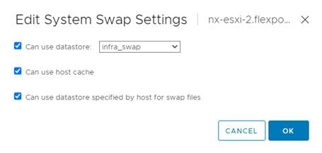
6. Click OK to save the configuration changes.
7. In the list under Virtual Machines, select Swap File Location.
8. In the window on the right, click EDIT.
9. Because of a known issue with the vCenter UI, use the TAB key to move the cursor to the first datastore in the datastore list. Then use the arrow keys to move the highlight to the infra_swap datastore. Once the infra_swap datastore is highlighted, use the spacebar to select it and click OK.
10. Repeat this step for all the ESXi hosts.
Verify ESXi Host Fibre Channel Multi-Path configuration
For FC SAN-booted ESXi hosts, verify that the boot disk contains all required FC paths.
1. In the vCenter HTML5 Interface, under Hosts and Clusters choose the ESXi host.
2. In the center pane, choose the Configure tab.
3. In the list under Storage, choose Storage Devices. Make sure the NETAPP Fibre Channel Disk is selected.
4. Choose the Paths tab.
5. Ensure that 4 FC paths appear, two of which should have the status Active (I/O).
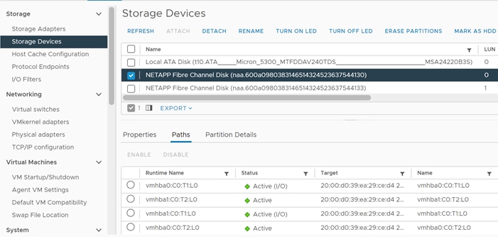
VMware ESXi 7.0 U2 TPM Attestation
If your Cisco UCS servers have Trusted Platform Module (TPM) 2.0 modules installed, the TPM can provide assurance that ESXi has booted with UEFI Secure Boot enabled and using only digitally signed code. In the Cisco UCS Configuration section of this document, UEFI secure boot was enabled in the boot policy. A server can boot with UEFI Secure Boot with or without a TPM 2.0 module. If it has a TPM, VMware vCenter can attest that the server booted with UEFI Secure Boot. To configure the VMware ESXi 7.0 U2 TPM, follow these steps:
1. For Cisco UCS servers that have TPM 2.0 modules installed, TPM Attestation can be verified in the vSphere HTML5 Client.
2. In the vCenter HTML5 Interface, under Hosts and Clusters choose the cluster.
3. In the center pane, choose the Monitor tab.
4. Click Monitor > Security. The Attestation status will show the status of the TPM:
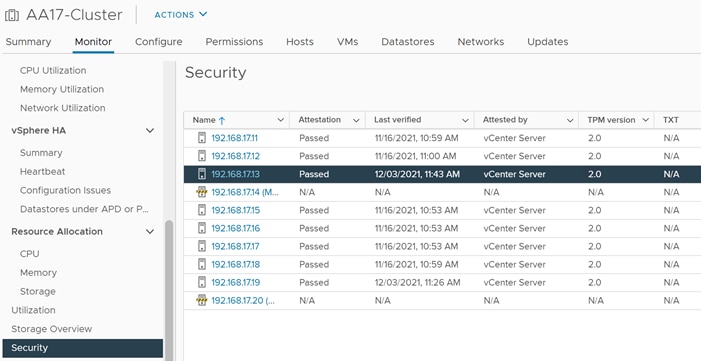
![]() It may be necessary to disconnect and reconnect or reboot a host from vCenter to get it to pass attestation the first time.
It may be necessary to disconnect and reconnect or reboot a host from vCenter to get it to pass attestation the first time.
Finalize the ONTAP configuration
Make the following configuration changes to finalize the NetApp controller configuration.
Configure DNS
To configure DNS for the Infra-SVM, run the following commands:
dns create -vserver <vserver name> -domains <dns-domain> -nameserve <dns-servers>
Example:
dns create -vserver Infra-SVM -domains cspg.local -nameservers 10.81.72.40,10.81.72.41
Delete Residual Default Domains (Applicable for 2-node cluster only)
To delete the Default domains that are not in use, run the following commands:
broadcast-domain delete -broadcast-domain <broad-domain-name>
Use the following command to find unused default domains:
broadcast-domain show
Test Auto Support
To test the Auto Support configuration by sending a message from all nodes of the cluster, run the following commands:
autosupport invoke -node * -type all -message “FlexPod storage configuration completed”
The configuration in this section is only required for configuring NVMe over Fabric.
NetApp ONTAP NVMe Configuration
To configure NetApp ONTAP NVMe, follow these steps:
1. Create NVMe namespace:
vserver nvme namespace create -vserver <SVM_name> -path <path> -size <size_of_namespace> -ostype <OS_type>
AA17-A400::> vserver nvme namespace create -vserver Infra-SVM -path /vol/NVMe_Datastore_01/NVMe_namespace_01 -ostype vmware -size 500G
2. Create NVMe subsystem:
vserver nvme subsystem create -vserver <SVM_name> -subsystem <name_of_subsystem> -ostype <OS_type>
AA17-A400:> vserver nvme subsystem create -vserver Infra-SVM -subsystem nvme_infra_hosts -ostype vmware
3. Verify the subsystem was created:
AA17-A400::> vserver nvme subsystem show -vserver Infra-SVM
Vserver Subsystem Target NQN
------- ------------ --------------------------------------------------------
Infra-SVM
nvme_infra_hosts
nqn.1992-08.com.netapp:sn.e01bbb1de4f911ebac6fd039ea166b8c:subsystem. nvme_infra_hosts
VMware vSphere NVMe Configuration
Configure NVMe over FC on ESXi Host
To configure NVMe over FC on all the NVMe ESXi hosts, follow these steps:
1. Enable NVMe/FC with Asymmetric Namespace Access (ANA):
[root@AA17-ESXi-FC-07:~] esxcfg-advcfg -s 0 /Misc/HppManageDegradedPaths
2. Reboot the Host. After reboot, verify that the HppManageDegradedPaths parameter is now disabled:
[root@AA17-ESXi-FC-07:~] esxcfg-advcfg -g /Misc/HppManageDegradedPaths
The Value of HppManageDegradedPaths is 0
3. Get the ESXi host NQN string and add this to corresponding subsystem on the ONTAP array:
[root@AA17-ESXi-FC-07:~] esxcli nvme info get
Host NQN: nqn.2014-08.com.vmware:nvme:AA17-ESXi-FC-07
4. Add the host NQN(s) obtained in the last step to the NetApp ONTAP subsystem one by one:
AA17-A400::> vserver nvme subsystem host add -vserver Infra-SVM -subsystem nvme_infra_hosts -host-nqn nqn.2014-08.com.vmware:nvme:AA17-ESXi-FC-07
AA17-A400::> vserver nvme subsystem host add -vserver Infra-SVM -subsystem nvme_infra_hosts -host-nqn nqn.2014-08.com.vmware:nvme:AA17-ESXi-FC-08
![]() It is important to add the host NQNs using separate commands as shown. ONTAP will accept a comma separated list of host NQNs without generating an error message however the ESXi hosts will not be able to map the namespace.
It is important to add the host NQNs using separate commands as shown. ONTAP will accept a comma separated list of host NQNs without generating an error message however the ESXi hosts will not be able to map the namespace.
5. Verify the host NQNs were added successfully:
AA17-A400::> vserver nvme subsystem host show
Vserver Subsystem Host NQN
------- --------- ----------------------------------------------------------
Infra-SVM
nvme_infra_hosts
nqn.2014-08.com.vmware:nvme:AA17-ESXi-FC-07
nqn.2014-08.com.vmware:nvme:AA17-ESXi-FC-08
2 entries were displayed.
![]() In the example above, host NQNs for two FC ESXi hosts in an ESXi cluster were added to the same subsystem to create a shared datastore.
In the example above, host NQNs for two FC ESXi hosts in an ESXi cluster were added to the same subsystem to create a shared datastore.
6. Map the Namespace to the subsystem:
AA17-a400::> vserver nvme subsystem map add -vserver Infra-SVM -subsystem nvme_infra_hosts -path /vol/NVMe_datastore_01/NVMe_namespace_01
7. Verify the Namespace is mapped to the subsystem:
AA17-A400::> vserver nvme subsystem map show -vserver Infra-SVM -instance
Vserver Name: Infra-SVM
Subsystem: nvme_infra_host_01
NSID: 00000001h
Namespace Path: /vol/NVMe_Datastore_01/NVMe_namespace_01
Namespace UUID: 01add6cf-d1c3-4d17-92f9-149f683a1e4d
8. Reboot each ESXi host and then verify that the ONTAP target NVMe/FC controllers are properly discovered on the ESXi Host:
[root@AA17-ESXi-FC-07:~] esxcli nvme controller list
Name Controller Number Adapter Transport Type Is Online
--------------------------------------------------------------------------------------------------------------------------------- ----------------- ------- -------------- ---------
nqn.1992-08.com.netapp:sn.63144a05ad1211eb8a7ad039ea29d44a:subsystem.nvme_infra_hosts#vmhba65#2005d039ea29ced4:2008d039ea29ced4 259 vmhba65 FC true
nqn.1992-08.com.netapp:sn.63144a05ad1211eb8a7ad039ea29d44a:subsystem.nvme_infra_hosts#vmhba64#2005d039ea29ced4:2006d039ea29ced4 260 vmhba64 FC true
nqn.1992-08.com.netapp:sn.63144a05ad1211eb8a7ad039ea29d44a:subsystem.nvme_infra_hosts#vmhba65#2005d039ea29ced4:2009d039ea29ced4 265 vmhba65 FC true
nqn.1992-08.com.netapp:sn.63144a05ad1211eb8a7ad039ea29d44a:subsystem.nvme_infra_hosts#vmhba64#2005d039ea29ced4:2007d039ea29ced4 266 vmhba64 FC true
ESXi Host NVMe over FC Datastore Configuration
To configure the ESXi host NVMe over FC datastore, follow these steps:
1. To verify that the NVMe Fibre Channel Disk is mounted on each ESXi host, log into the VMware vCenter using a web-browser.
2. Under Hosts and Clusters select the ESXi host. In the center pane, select Configure > Storage > Storage Devices. The NVMe Fibre Channel Disk should be listed under Storage Devices.
3. Select the NVMe Fibre Channel Disk, then select Paths underneath. Verify 2 paths have a status of Active (I/O) and 2 paths have a status of Active.
![]() During lab verification
During lab verification
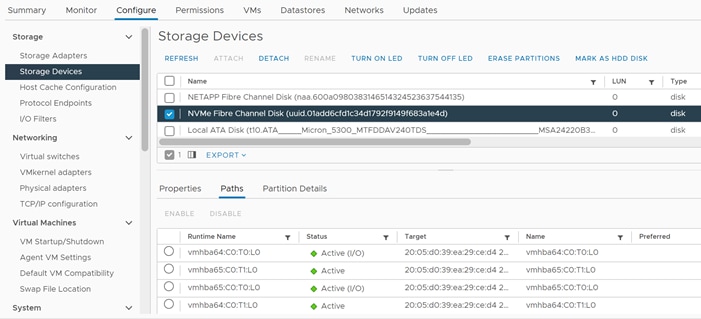
4. Repeat step 4 for all the NVMe hosts.
5. For one of these hosts, right-click the host under Hosts and Clusters and select Storage > New Datastore. Leave VMFS selected and click NEXT.
6. Name the datastore (for example, FC_NVMe_DS_01) and select the NVMe Fibre Channel Disk. Click NEXT.
7. Leave VMFS 6 selected and click NEXT.
8. Leave all Partition configuration values at the default values and click NEXT.
9. Review the information and click FINISH.
10. Select Storage and select the new NVMe datastore. In the center pane, select Hosts. Ensure all the NVMe hosts have mounted the datastore.
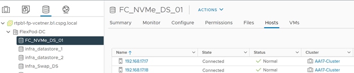
FlexPod Management Tools Setup
Cisco Intersight Hardware Compatibility List (HCL) Status
Cisco Intersight evaluates the compatibility of customer’s UCS system to check if the hardware and software have been tested and validated by Cisco or Cisco partners. Intersight reports validation issues after checking the compatibility of the server model, processor, firmware, adapters, operating system and drivers, and displays the compliance status with the Hardware Compatibility List (HCL).
To determine HCL compatibility for VMware ESXi, Cisco Intersight uses Cisco UCS Tools. The Cisco UCS Tools is part of VMware ESXi Cisco custom ISO, and no additional configuration is required.
![]() For more details on Cisco UCS Tools manual deployment and troubleshooting, refer to: https://intersight.com/help/saas/resources/cisco_ucs_tools#about_cisco_ucs_tools
For more details on Cisco UCS Tools manual deployment and troubleshooting, refer to: https://intersight.com/help/saas/resources/cisco_ucs_tools#about_cisco_ucs_tools
To find detailed information about the hardware compatibility of a compute node, in Intersight select Servers in the left menu bar, click a server, select HCL.
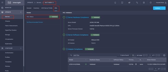
NetApp ONTAP Tools 9.8P1 Deployment
The ONTAP tools for VMware vSphere provide end-to-end life cycle management for virtual machines in VMware environments that use NetApp storage systems. It simplifies storage and data management for VMware environments by enabling administrators to directly manage storage within the vCenter Server. This section describes the deployment procedures for the NetApp ONTAP Tools for VMware vSphere
NetApp ONTAP Tools for VMware vSphere 9.8P1 Pre-installation Considerations
The following licenses are required for ONTAP Tools on storage systems that run ONTAP 9.8 or above:
● Protocol licenses (NFS, FCP, and/or iSCSI)
● NetApp FlexClone® ((optional) Required for performing test failover operations for SRA and for
vVols operations of VASA Provider.
● NetApp SnapRestore® (for backup and recovery).
● The NetApp SnapManager® Suite.
● NetApp SnapMirror® or NetApp SnapVault® (Optional - required for performing failover operations for SRA and VASA Provider when using vVols replication).
![]() The Backup and Recovery capability has been integrated with SnapCenter and requires additional licenses for SnapCenter to perform backup and recovery of virtual machines and applications.
The Backup and Recovery capability has been integrated with SnapCenter and requires additional licenses for SnapCenter to perform backup and recovery of virtual machines and applications.
Table 19. Port Requirements for NetApp ONTAP Tools
| TCP Port |
Requirement |
| 443 (HTTPS) |
Secure communications between VMware vCenter Server and the storage systems |
| 8143 (HTTPS) |
ONTAP Tools listens for secure communications |
| 9083 (HTTPS) |
VASA Provider uses this port to communicate with the vCenter Server and obtain TCP/IP settings |
| 7 |
ONTAP tools sends an echo request to ONTAP to verify reachability and is required only when adding storage system and can be disabled later. |
The requirements for deploying NetApp ONTAP Tools are listed here.
To install the NetApp ONTAP tools for VMware vSphere 7.0U2 software by using an Open Virtualization Format (OVF) deployment, follow these steps:
1. Download the NetApp ONTAP Tools 9.8P1 OVA (NETAPP-ONTAP-TOOLS-FOR-VMWARE-VSPHERE-9.8P1-7879.OVA) from NetApp support: https://mysupport.netapp.com/site/products/all/details/otv/downloads-tab/download/63792/9.8P1
2. Launch the vSphere Web Client and navigate to Hosts and Clusters.
3. Select ACTIONS for the FlexPod-DC datacenter and select Deploy OVF Template.
4. Browse to the ONTAP tools OVA file and select the file.
5. Enter the VM name and select a datacenter or folder to deploy the VM and click NEXT.
6. Select a host cluster resource to deploy OVA and click NEXT.
7. Review the details and accept the license agreement.
8. Select the infra_datastore_2 volume and Select the Thin Provision option for the virtual disk format.
9. From Select Networks, select a destination network (for example, IB-MGMT) and click NEXT.
10. From Customize Template, enter the ONTAP tools administrator password, vCenter name or IP address and other configuration details and click NEXT.
11. Review the configuration details entered and click FINISH to complete the deployment of NetApp ONTAP-Tools VM.
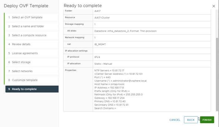
12. Power on the ONTAP-tools VM and open the VM console.
13. During the ONTAP-tools VM boot process, you see a prompt to install VMware Tools. From vCenter, right-click the ONTAP-tools VM > Guest OS > Install VMware Tools.
14. Networking configuration and vCenter registration information was provided during the OVF template customization, therefore after the VM is up and running, ONTAP-Tools and vSphere API for Storage Awareness (VASA) is registered with vCenter.
15. Refresh the vCenter Home Screen and confirm that the ONTAP tools is installed.
![]() The NetApp ONTAP tools vCenter plug-in is only available in the vSphere HTML5 Client and is not available in the vSphere Web Client.
The NetApp ONTAP tools vCenter plug-in is only available in the vSphere HTML5 Client and is not available in the vSphere Web Client.
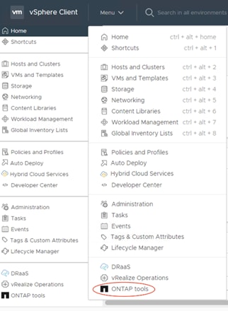
Download the NetApp NFS Plug-in for VAAI
The NFS Plug-in for VAAI was previously installed on the ESXi hosts along with the Cisco UCS VIC drivers; it is not necessary to re-install the plug-in at this time. However, for any future additional ESXi host setup, instead of using esxcli commands, NetApp ONTAP-Tools can be utilized to install the NetApp NFS plug-in. The steps below upload the latest version of the plugin to ONTAP tools.
1. Download the NetApp NFS Plug-in 2.0 for VMware file from: https://mysupport.netapp.com/site/products/all/details/nfsplugin-vmware-vaai/downloads-tab.
2. Unzip the file and extract NetApp_bootbank_NetAppNasPlugin_2.0-15.vib from vib20 > NetAppNasPlugin.
3. Rename the .vib file to NetAppNasPlugin.vib to match the predefined name that ONTAP tools uses.
4. Click Settings in the ONTAP tool Getting Started page.
5. Click NFS VAAI Tools tab.
6. Click Change in the Existing version section.
7. Browse and select the renamed .vib file, and then click Upload to upload the file to the virtual appliance.
![]() The next step is only required on the hosts where NetApp VAAI plug-in was not installed alongside Cisco VIC driver installation.
The next step is only required on the hosts where NetApp VAAI plug-in was not installed alongside Cisco VIC driver installation.
8. In the Install on ESXi Hosts section, select the ESXi host where the NFS Plug-in for VAAI is to be installed, and then click Install.
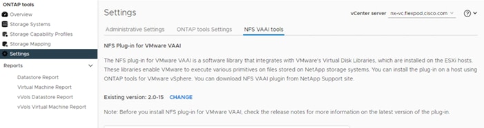
9. Reboot the ESXi host after the installation finishes.
The VASA provider for ONTAP is enabled by default during the installation of the NetApp ONTAP tools. To verify the VASA provider was enabled, follow these steps:
1. From the vSphere Client, click Menu > ONTAP tools.
2. Click Settings.
3. Click Manage Capabilities in the Administrative Settings tab.
4. In the Manage Capabilities dialog box, click Enable VASA Provider if it was not pre-enabled.
5. Enter the IP address of the virtual appliance for ONTAP tools, VASA Provider, and VMware Storage Replication Adapter (SRA) and the administrator password, and then click Apply.
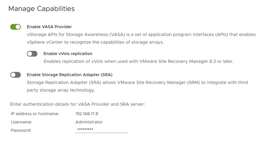
Discover and Add Storage Resources
To Add storage resources for the Monitoring and Host Configuration capability and the Provisioning and Cloning capability, follow these steps:
1. Using the vSphere Web Client, log in to the vCenter. If the vSphere Web Client was previously opened, close the tab, and then reopen it.
2. In the Home screen, click the Home tab and click ONTAP tools.
![]() When using the cluster admin account, add storage from the cluster level.
When using the cluster admin account, add storage from the cluster level.
![]() You can modify the storage credentials with the vsadmin account or another SVM level account with role-based access control (RBAC) privileges. Refer to the ONTAP 9 Administrator Authentication and RBAC Power Guide for additional information.
You can modify the storage credentials with the vsadmin account or another SVM level account with role-based access control (RBAC) privileges. Refer to the ONTAP 9 Administrator Authentication and RBAC Power Guide for additional information.
3. Click Overview > Getting Started, and then click ADD under Add Storage System.
4. Specify the vCenter Server where the storage will be located.
5. In the IP Address/Hostname field, enter the storage cluster management IP.
6. Confirm Port 443 to Connect to this storage system.
7. Enter admin for the username and the admin password for the cluster.
8. Click Save to add the storage configuration to ONTAP tools.
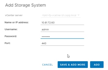
9. Wait for the Storage Systems to update. You might need to click Refresh to complete this update.
To discover the cluster and, follow these steps:
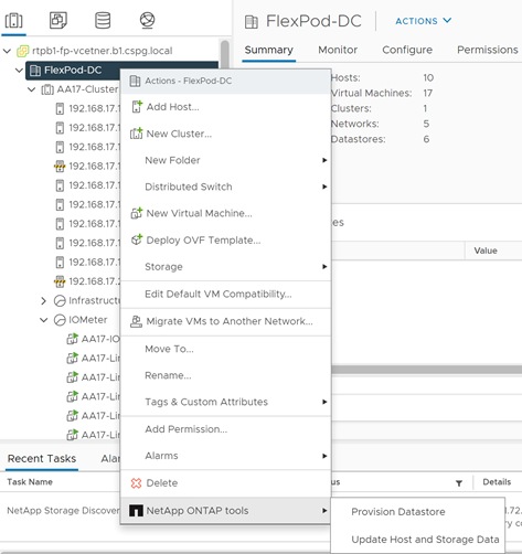
10. From the vSphere Client Home page, click Hosts and Clusters.
11. Right-click the FlexPod-DC datacenter, click NetApp ONTAP tools > Update Host and Storage Data.
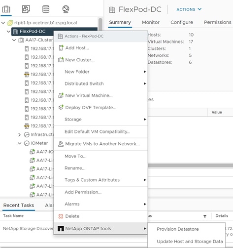
12. On the Confirmation dialog box, click OK. It might take a few minutes to update the data.
Optimal Storage Settings for ESXi Hosts
ONTAP tools enables the automated configuration of storage-related settings for all ESXi hosts that are connected to NetApp storage controllers. To use these settings, follow these steps:
1. From the VMware vSphere Web Client Home page, click vCenter > Hosts and Clusters.
2. Select a host and then click Actions > NetApp ONTAP tools > Set Recommended Values.
3. In the NetApp Recommended Settings dialog box, select all the applicable values for the ESXi host.
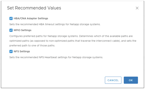
![]() This functionality sets values for HBAs and converged network adapters (CNAs), sets appropriate paths and path-selection plug-ins, and verifies appropriate settings for NFS I/O. A vSphere host reboot may be required after applying the settings.
This functionality sets values for HBAs and converged network adapters (CNAs), sets appropriate paths and path-selection plug-ins, and verifies appropriate settings for NFS I/O. A vSphere host reboot may be required after applying the settings.
4. Click OK.
Provision Datastores using ONTAP Tools (Optional)
Using ONTAP tools, the administrator can provision an NFS, FC, FC-NVMe or iSCSI datastore and attach it to a single or multiple hosts in the cluster. The following steps describe provisioning a datastore and attaching it to the cluster.
![]() It is a NetApp best practice to use ONTAP tools to provision any additional datastores for the FlexPod infrastructure. When using VSC to create vSphere datastores, all NetApp storage best practices are implemented during volume creation and no additional configuration is needed to optimize performance of the datastore volumes.
It is a NetApp best practice to use ONTAP tools to provision any additional datastores for the FlexPod infrastructure. When using VSC to create vSphere datastores, all NetApp storage best practices are implemented during volume creation and no additional configuration is needed to optimize performance of the datastore volumes.
Storage Capabilities
A storage capability is a set of storage system attributes that identifies a specific level of storage performance (storage service level), storage efficiency, and other capabilities such as encryption for the storage object that is associated with the storage capability.
Create the Storage Capability Profile
In order to leverage the automation features of VASA two primary components must first be configured. The Storage Capability Profile (SCP) and the VM Storage Policy. The Storage Capability Profile expresses a specific set of storage characteristics into one or more profiles used to provision a Virtual Machine. The SCP is specified as part of VM Storage Policy. NetApp ONTAP tools comes with several pre-configured SCPs such as Platinum, Bronze, and so on.
![]() The ONTAP tools for VMware vSphere plug-in also allows customers to set Quality of Service (QoS) rule using a combination of maximum and/or minimum IOPs.
The ONTAP tools for VMware vSphere plug-in also allows customers to set Quality of Service (QoS) rule using a combination of maximum and/or minimum IOPs.
To review or edit one of the built-in profiles pre-configured with ONTAP tools, follow these steps:
1. From the vCenter console, click Menu > ONTAP tools.
2. In the NetApp ONTAP tools click Storage Capability Profiles.
3. Select the Platinum Storage Capability Profile and select Clone from the toolbar.
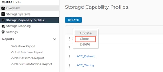
4. Enter a name for the cloned SCP (for example, AFF_Platinum_Encrypted) and add a description if desired. Click NEXT.
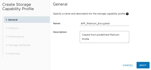
5. Select All Flash FAS(AFF) for the storage platform and click NEXT.
6. Select None to allow unlimited performance or set a the desired minimum and maximum IOPS for the QoS policy group. Click NEXT.
7. On the Storage attributes page, change the Encryption and Tiering policy to the desired settings and click NEXT. In the example below, Encryption was turned.
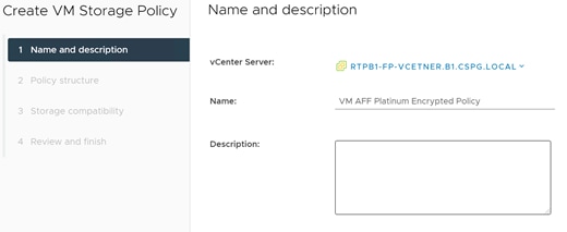
8. Review the summary page and click FINISH to create the storage capability profile.
![]() It is recommended to Clone the Storage Capability Profile if you wish to make any changes to the predefined profiles rather than editing the built-in profile.
It is recommended to Clone the Storage Capability Profile if you wish to make any changes to the predefined profiles rather than editing the built-in profile.
Create a VM storage policy and associate SCP to the datastore that meets the requirements defined in the SCP. To create a new VM Storage policy, follow these steps:
1. From the vCenter console, click Menu > Policies and Profiles.
2. Select VM Storage Policies and click CREATE.
3. Create a name for the VM storage policy and enter a description and click NEXT.

4. Choose Enable rules for NetApp.clustered.Data.ONTAP.VP.VASA10 storage located under the Datastore specific rules section and click NEXT.
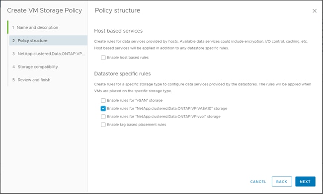
5. On the Placement tab select the SCP created in the previous step and click NEXT.
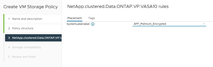
6. All the datastores with matching capabilities are displayed, click NEXT.
7. Review the policy summary and click FINISH.
Provision NFS Datastore
To provision the NFS datastore, follow these steps:
1. From the vCenter console, click Menu > ONTAP tools.
2. From the ONTAP tools Home page, click Overview.
3. In the Getting Started tab, click Provision.
4. Click Browse to choose the destination to provision the datastore.
5. Select the type as NFS and Enter the datastore name (for example, NFS_DS_1).
6. Provide the size of the datastore and the NFS Protocol.
7. Check the storage capability profile and click NEXT.
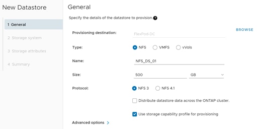
8. Choose the desired Storage Capability Profile, cluster name and the desired SVM to create the datastore. In this example, the Infra-SVM is selected.

9. Click NEXT.
10. Select the aggregate name and click NEXT.
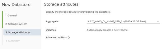
11. Review the Summary and click FINISH.
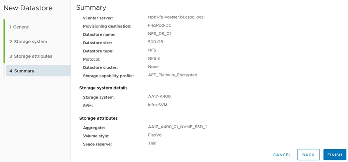
![]() The datastore is created and mounted on the hosts in the cluster. Click Refresh from the vSphere Web Client to see the newly created datastore.
The datastore is created and mounted on the hosts in the cluster. Click Refresh from the vSphere Web Client to see the newly created datastore.
![]() Distributed datastore is supported from ONTAP 9.8, which provides FlexGroup volume on ONTAP storage. To create a Distributed Datastore across the ONTAP Cluster select NFS 4.1 and check the box for Distributed Datastore data across the ONTAP Cluster as shown below.
Distributed datastore is supported from ONTAP 9.8, which provides FlexGroup volume on ONTAP storage. To create a Distributed Datastore across the ONTAP Cluster select NFS 4.1 and check the box for Distributed Datastore data across the ONTAP Cluster as shown below.
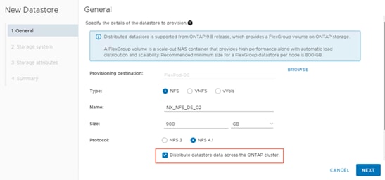
Provision FC Datastore
To provision the FC datastore, follow these steps:
1. From the vCenter console, click Menu > ONTAP tools.
2. From the ONTAP tools Home page, click Overview.
3. In the Getting Started tab, click Provision.
4. Click Browse to choose the destination to provision the datastore.
5. Select the type as VMFS and Enter the datastore name.
6. Provide the size of the datastore and the FC Protocol.
7. Check the Use storage capability profile and click NEXT.
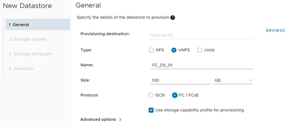
8. Select the Storage Capability Profile, Storage System and the desired Storage VM to create the datastore.
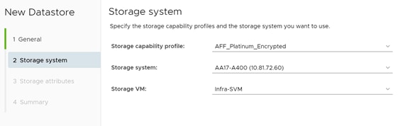
9. Click NEXT.
10. Choose the aggregate name and click NEXT.
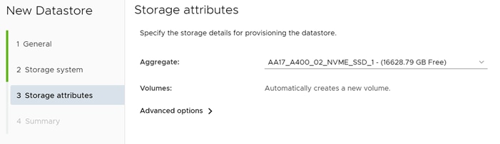
11. Review the Summary and click FINISH.
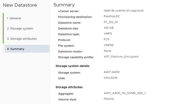
12. Click OK.
![]() The datastore is created and mounted on all the hosts in the cluster. Click Refresh from the vSphere Web Client to see the newly created datastore.
The datastore is created and mounted on all the hosts in the cluster. Click Refresh from the vSphere Web Client to see the newly created datastore.
Create Virtual Machine with Assigned VM Storage Policy
To create a virtual machine assigned to a VM storage policy, follow these steps:
1. Log into vCenter and navigate to the VMs and Templates tab and click to select the datacenter (for example, Flexpod-DC).
2. Click Actions and click New Virtual Machine.
3. Choose Create a new virtual machine and click NEXT.
4. Enter a name for the VM and select the datacenter (for example, FlexPod-DC).
5. Select the cluster (for example, AA17-Cluster) and click NEXT.
6. Select the VM storage policy from the selections and select a compatible datastore. Click NEXT.
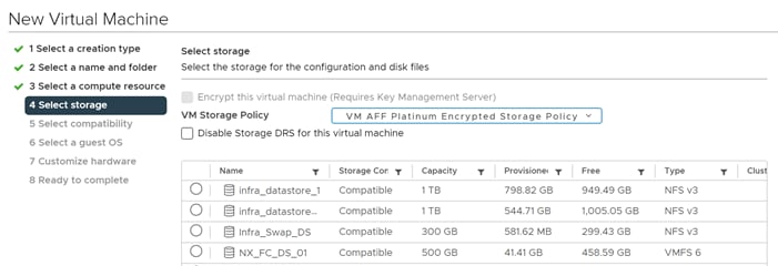
7. Choose Compatibility (for example, ESXi 7.0 U2 or later) and click NEXT.
8. Choose the Guest OS and click NEXT.
9. Customize the hardware for the VM and click NEXT.
10. Review the details and click FINISH.
By selecting the VM storage policy in Step 6, the VM will be deployed on the compatible datastores.
Virtual Volumes – vVol (Optional)
NetApp VASA Provider enables customers to create and manage VMware virtual volumes (vVols). A vVols datastore consists of one or more FlexVol volumes within a storage container (also called "backing storage"). A virtual machine can be spread across one vVols datastore or multiple vVols datastores. All of the FlexVol volumes within the storage container must use the same protocol (NFS, iSCSI, or FCP) and the same SVMs.
![]() Lab testing has shown that if a virtual machine (VM) has one or more disks in vVol datastores and the VM is migrated to another host, under heavy load the VM can be stunned or frozen for 45 or more seconds.
Lab testing has shown that if a virtual machine (VM) has one or more disks in vVol datastores and the VM is migrated to another host, under heavy load the VM can be stunned or frozen for 45 or more seconds.
Verify NDMP Vserver Scope Mode
To verify the NDMP Vserver scope mode, follow these steps:
1. View NDMP scope mode with the following command:
AA17-A400::> system services ndmp node-scope-mode status
NDMP node-scope-mode is disabled.
2. If NDMP node-scope is enabled, disable NDMP node-scoped mode:
system services ndmp node-scope-mode off
3. Enable NDMP services on the SVM:
vserver add-protocols -protocols ndmp -vserver Infra-SVM
vserver services ndmp on -vserver Infra-SVM
Create the Storage Capability Profile
Select one or more VASA Provider storage capability profiles for a vVols datastore. A default storage capability profile can also be specified for any vVols datastores that are automatically created in that storage container.
To create storage capability profile for the vVol datastore, follow these steps:
1. From the vCenter console, click Menu > ONTAP tools.
2. From the ONTAP tools Home page, click Storage Capability Profiles.
3. Choose the Platinum Storage Capability Profile and select Clone from the toolbar.
4. Enter a name for the cloned SCP (for example, AFF_Gold_Encrypted_VVOL) and add a description if desired. Click NEXT.
5. Select All Flash FAS(AFF) for the storage platform and click Next.
6. Select None to allow unlimited performance or set a the desired minimum and maximum IOPS for the QoS policy group. Selecting a value for Max IOPS enables customers to use the QoS functionality.
![]() When applied for a virtual datastore, a QoS policy with "MAX IOPS" value is created for each data vVols.
When applied for a virtual datastore, a QoS policy with "MAX IOPS" value is created for each data vVols.
![]() When you select ONTAP Service Level, then the existing adaptive QoS policies of ONTAP are applied to a data vVols. You can select one of three service levels: Extreme, Performance, or Value. The ONTAP service level is applicable only to vVols datastores.
When you select ONTAP Service Level, then the existing adaptive QoS policies of ONTAP are applied to a data vVols. You can select one of three service levels: Extreme, Performance, or Value. The ONTAP service level is applicable only to vVols datastores.
7. On the Storage attributes page, change the Encryption and Tiering policy to the desired settings and click NEXT.
8. Review the summary page and choose FINISH to create the storage capability profile.
Create a VM storage policy and associate a storage capability profile (SCP) to the datastore that meets the requirements defined in the SCP. To create a new VM Storage policy, follow these steps:
1. From the vCenter console, click Menu > Policies and Profiles.
2. Select VM Storage Policies and click CREATE.
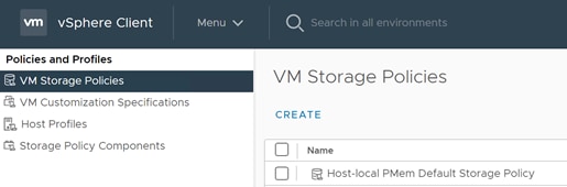
3. Enter a new name for the VM storage Policy and click NEXT.
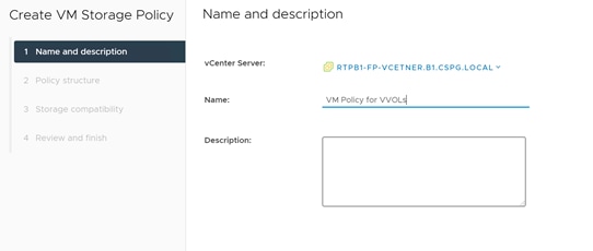
4. Select Enable rules for NetApp.clustered.Data.ONTAP.VP.VASA.10 storage and NetApp.clustered.Data.ONTAP.VP.vvol storage and click NEXT.
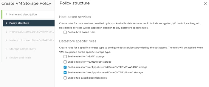
5. Select a pre-defined SCP or SCP created in the previous step under BOTH NetApp.clustered.Data.ONTAP.VP.VASA10 and NetApp.clustered.Data.ONTAP.VP.vvol rules. Click NEXT.
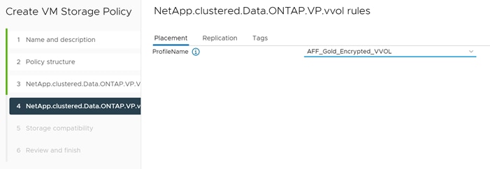
6. The datastores (if any) with matching capabilities are displayed, click NEXT.
7. Review the Policy Summary and click Finish.
To provision the vVols datastore over NFS protocol, follow these steps:
1. From the vCenter console, click Menu > ONTAP tools.
2. From the NetApp ONTAP tools Home page, click Overview.
3. In the Getting Started tab, click Provision.
4. Click Browse to select the destination cluster to provision the datastore.
5. Select the type as vVols and Enter the datastore name.
6. Select NFS for protocol and click NEXT.
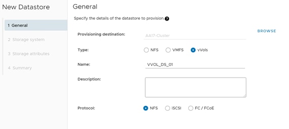
7. Select the Storage capability profile previously created for vVols.
8. Select the Storage system and the Storage SVM. Click NEXT.
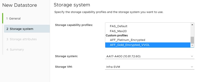
9. Select Create new volumes.
10. Enter the name and size for one or more vVols and Click ADD.
![]() You can create multiple vVols for a datastore.
You can create multiple vVols for a datastore.
11. Verify the correct Default storage capability profile is selected. click NEXT.
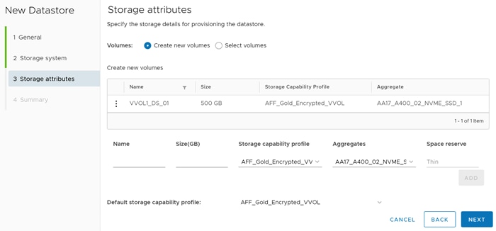
12. Review all the fields on the summary page and click FINISH.
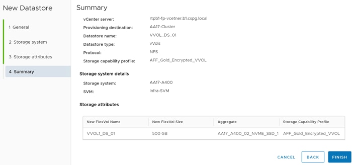
13. Verify in the vVols Datastore report the vVols is mounted correctly, under ONTAP tools > Reports > vVols Datastore Report.
![]() Customers might need to rediscover the storage systems (ONTAP tools > Storage Systems > Rediscover All). In some case, log-out and log-back-in for vCenter might be required.
Customers might need to rediscover the storage systems (ONTAP tools > Storage Systems > Rediscover All). In some case, log-out and log-back-in for vCenter might be required.
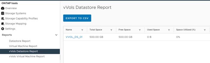
![]() vVols can also be configured for FC or ISCSI protocol using the steps outlined above and selecting a different protocol on the first screen.
vVols can also be configured for FC or ISCSI protocol using the steps outlined above and selecting a different protocol on the first screen.
The following actions can be performed on a vVols Datastore:
● Expand Storage of vVols Datastore
● Remove Storage from vVols Datastore
● Edit Properties of vVols Datastore
● Mount vVols Datastore
● Delete vVols Datastore
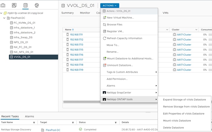
Create a Virtual Machine on a vVols Datastore
To provision a virtual machine on a vVols datastore and assigned Virtual Machine Storage Policy, follow these steps:
1. Navigate to vSphere Client > VMs and Templates > Actions > New Virtual Machine.
2. Select Create a new virtual machine and click NEXT.
3. Enter the name for the VM (for example, IOM_VVOL_01) and select the datacenter (for example, FlexPod-DC). Click NEXT.
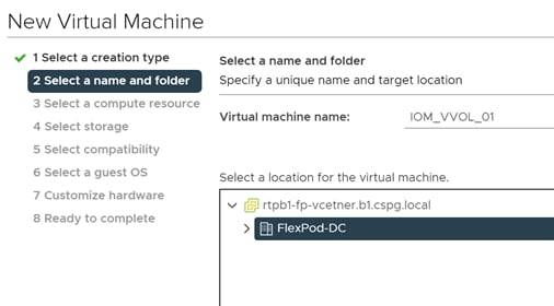
4. Select the cluster and click NEXT.
5. Select the VM Storage Policy and vVol datastore. Verify Compatibility checks succeeded.
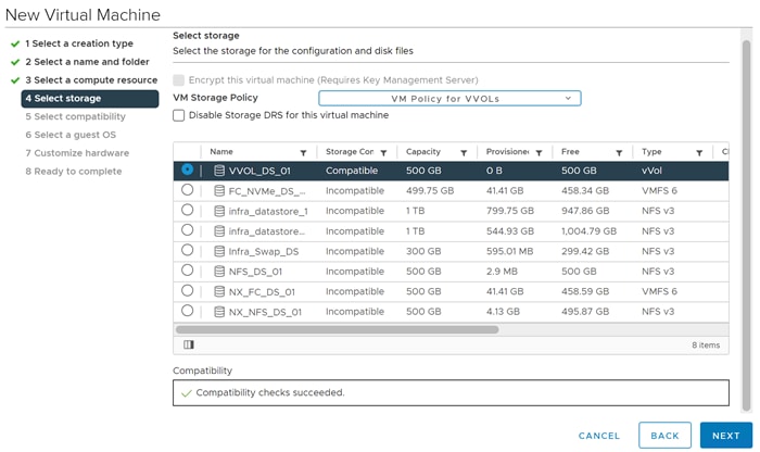
6. Click NEXT.
7. Select Compatibility (for example, ESXi 7.0 U2 and later) and click NEXT.
8. Select Guest OS Family (for example, Linux) and Guest OS version (for example, CentOS 7) and click NEXT.
9. Select the hardware parameters (CPU, Memory, HDD etc.) and click NEXT.
10. Review the settings and click FINISH.
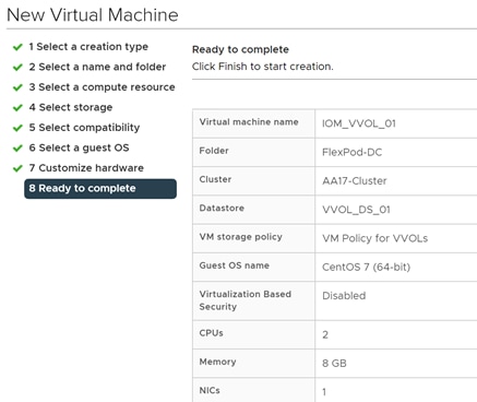
11. Verify that the VM is created successfully and install operating system on the VM.
NetApp SnapCenter 4.5 installation
SnapCenter Software is a centralized and scalable platform that provides application-consistent data protection for applications, databases, host file systems, and VMs running on ONTAP systems anywhere in the Hybrid Cloud.
NetApp SnapCenter Architecture
The SnapCenter platform is based on a multitier architecture that includes a centralized management server (SnapCenter Server) and a SnapCenter host agent. The host agent that performs virtual machine and datastore backups for VMware vSphere is the SnapCenter Plug-in for VMware vSphere. It is packaged as a Linux appliance (Debian-based Open Virtual Appliance format) and is no longer part of the SnapCenter Plug-ins Package for Windows. Additional information on deploying SnapCenter server for application backups can be found in the documentation listed below.
This guide focuses on deploying and configuring the SnapCenter plug-in for VMware vSphere to protect virtual machines and VM datastores.
![]() Customers must install SnapCenter Server and the necessary plug-ins to support application-consistent backups for Microsoft SQL, Microsoft Exchange, Oracle databases and SAP HANA. Application-level protection is beyond the scope of this deployment guide.
Customers must install SnapCenter Server and the necessary plug-ins to support application-consistent backups for Microsoft SQL, Microsoft Exchange, Oracle databases and SAP HANA. Application-level protection is beyond the scope of this deployment guide.
Refer to the SnapCenter documentation for more information or the application specific CVD’s and technical reports for detailed information on how to deploy SnapCenter for a specific application configuration.
● SnapCenter Documentation: https://docs.netapp.com/us-en/snapcenter/index.html
● Deploy FlexPod Datacenter for Microsoft SQL Server 2019 with VMware 7.0 on Cisco UCS B200 M6 and NetApp ONTAP 9.8:
https://www.cisco.com/c/en/us/products/collateral/servers-unified-computing/ucs-b-series-blade-servers/flexpod-sql-2019-vmware-on-ucs-netapp-ontap-wp.html
● SnapCenter Plug-in for VMware vSphere Documentation: https://mysupport.netapp.com/documentation/docweb/index.html?productID=63990&language=en-US
Host and Privilege Requirements for the SnapCenter Plug-In for VMware vSphere
Review the following requirements before installing the SnapCenter Plug-in for VMware vSphere virtual appliance:
● SnapCenter Plug-in for VMware vSphere is deployed as a Linux based virtual appliance.
● Virtual appliance must not be deployed in a folder name with special characters.
● A separate, unique instance of the virtual appliance must be deployed for each vCenter Server.
Table 20. Port Requirements
| Port |
Requirement |
| 8080(HTTPS) bidirectional |
This port is used to manage the virtual appliance |
| 8144(HTTPs) bidirectional |
Communication between SnapCenter Plug-in for VMware vSphere and vCenter |
| 443 (HTTPS) |
Communication between SnapCenter Plug-in for VMware vSphere and vCenter |
License Requirements for SnapCenter Plug-In for VMware vSphere
The following licenses are required on the ONTAP storage system to backup and restore VM’s in the virtual infrastructure:
Table 21. SnapCenter Plug-in for VMware vSphere License Requirements
| Product |
License Requirements |
| ONTAP |
SnapManager Suite: Used for backup operations One of these: SnapMirror or SnapVault (for secondary data protection regardless of the type of relationship) |
| ONTAP Primary Destinations |
To perform protection of VMware VMs and datastores the following licenses should be installed: SnapRestore: used for restoring operations FlexClone: used for mount and attach operations |
| ONTAP Secondary Destinations |
To perform protection of VMware VMs and datastores only: FlexClone: used for mount and attach operations |
| VMware |
vSphere Standard, Enterprise, or Enterprise Plus A vSphere license is required to perform restore operations, which use Storage vMotion. vSphere Essentials or Essentials Plus licenses do not include Storage vMotion. |
![]() It is recommended (but not required) to add SnapCenter Standard licenses to secondary destinations. If SnapCenter Standard licenses are not enabled on secondary systems, SnapCenter cannot be used after a failover operation. A FlexClone license on secondary storage is required to perform mount and attach operations. A SnapRestore license is required to perform restore operations.
It is recommended (but not required) to add SnapCenter Standard licenses to secondary destinations. If SnapCenter Standard licenses are not enabled on secondary systems, SnapCenter cannot be used after a failover operation. A FlexClone license on secondary storage is required to perform mount and attach operations. A SnapRestore license is required to perform restore operations.
Download and Deploy the SnapCenter Plug-In for VMware vSphere 4.5
To download and deploy the SnapCenter Plug-in for VMware vSphere appliance, follow these steps:
1. Download SnapCenter Plug-in for VMware vSphere OVA file from NetApp support site (https://mysupport.netapp.com).
2. From VMware vCenter, navigate to the VMs and Templates tab, right-click the data center (for example, FlexPod-DC) and choose Deploy OVF Template.
3. Specify the location of the OVF Template and click NEXT.
4. On the Select a name and folder page, enter a unique name (for example, NX-SNAPCTR) and location (data center for example, FlexPod-DC) for the VM and click NEXT to continue.
5. On the Select a compute resource page, select the cluster and click NEXT.
6. On the Review details page, verify the OVA template details and click NEXT.
7. On the License agreements page, read and check the box I accept all license agreements. Click NEXT.
8. On the Select storage page, select a datastore, change the datastore virtual disk format to Thin Provision and click NEXT.
9. On the Select networks page, select s destination network for example, IB-MGMT and then click NEXT.
10. On the Customize template page, under Register to existing vCenter, enter the vCenter credentials.
11. In Create SCV credentials, create a username (for example, admin) and password for the SCV maintenance user.
12. In Setup Network Properties, enter the network information.
13. In Setup Date and Time, provide the NTP server address(es) and select the time zone where the vCenter is located.
14. Click NEXT.
15. On the Ready to complete page, review the page and click FINISH. The VM deployment will start. After the VM is deployed successfully, proceed to the next step.
16. Navigate to the SnapCenter VM, right click and select Power > Power On to start the virtual appliance.
17. While the virtual appliance is powering on, click Install VMware tools.
18. After the SnapCenter VM installation is complete and VM is ready to use, proceed to the next step.
19. Log into SnapCenter Plug-in for VMware vSphere using the IP address (https://<ip_address_of_SnapCenter>:8080 ) displayed on the appliance console screen with the credentials that you provided in the deployment wizard.
20. Verify on the Dashboard that the virtual appliance has successfully connected to vCenter and the SnapCenter Plug-in for VMware vSphere is successfully enabled and connected.
NetApp SnapCenter 4.5 configuration
SnapCenter Plug-In for VMware vSphere in vCenter Server
After successfully installing the SnapCenter Plug-in for VMware vSphere, follow these steps to setup VM backup.
1. Navigate to VMware vSphere Web Client URL https://<vCenter Server>
![]() If currently logged into vCenter, logoff, close the open tab and sign-on again to access the newly installed SnapCenter Plug-in for VMware vSphere.
If currently logged into vCenter, logoff, close the open tab and sign-on again to access the newly installed SnapCenter Plug-in for VMware vSphere.
2. After logging on, a blue banner will be displayed indicating the SnapCenter plug-in was successfully deployed. Click Refresh to activate the plug-in.
3. On the VMware vSphere Web Client page, select Menu > SnapCenter Plug-in for VMware vSphere to launch the SnapCenter Plug-in for VMware GUI.
To add storage systems, follow these steps:
1. Click Storage Systems.
2. Click +Add to add a storage system (or SVM).
3. Enter Storage System, user credentials, and other required information in following dialog box.
4. Check the box for Log SnapCenter server events to syslog and Send AutoSupport Notification for failed operation to storage system.
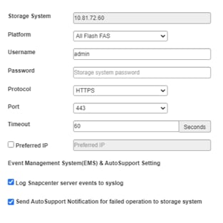
5. Click ADD.
Create Backup Policies for Virtual Machines and Datastores
To create backup policies for VMs and datastores, follow these steps:
1. From SnapCenter GUI, Click Policies.
2. On the Policies page, click +Create to create a new policy.
3. On the New Backup Policy page, follow these steps:
a. Enter the policy name and a description.
b. Enter the backups to keep.
4. From the Frequency drop-down list, select the backup frequency (hourly, daily, weekly, monthly, and on-demand only).
5. Expand the Advanced options and select VM Consistency and Include datastore with independent disks.
6. Click ADD.
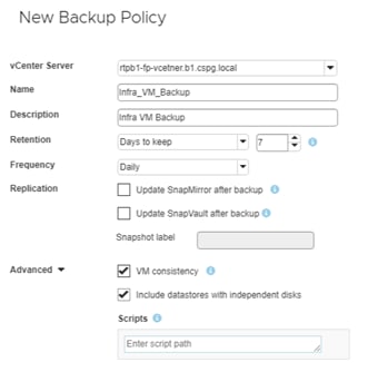
![]() Customers can create multiple policies as required for different sets of VMs or datastores.
Customers can create multiple policies as required for different sets of VMs or datastores.
Resource groups are groups of virtual machines or datastores that are backed up together. A backup policy is associated with the resource group to back up the virtual machines and retain a certain number of backups as defined in the policy.
To create resource groups, follow these steps:
1. In SnapCenter Plug-in Navigator, click Resource Groups.
2. Click +Create to create a new Resource Group.
![]() To create a resource group for one virtual machine, click VMs and Templates, right-click a virtual machine, choose NetApp SnapCenter from the drop-down list, and then choose Create Resource Group from the secondary drop-down list.
To create a resource group for one virtual machine, click VMs and Templates, right-click a virtual machine, choose NetApp SnapCenter from the drop-down list, and then choose Create Resource Group from the secondary drop-down list.
![]() To create a resource group for one datastore, click Storage, right-click a datastore, choose NetApp SnapCenter from the drop-down list, and then choose Create Resource Group from the secondary drop-down list.
To create a resource group for one datastore, click Storage, right-click a datastore, choose NetApp SnapCenter from the drop-down list, and then choose Create Resource Group from the secondary drop-down list.
3. In the General Info & notification page, enter the resource group name and complete the notification settings.
4. Select the Custom snapshot format option and choose the desired label for example, $ResourceGroup to have the resource group name appended to the snapshot name during snapshot operation.
5. Click Next.
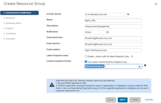
6. Select a datastore as the parent entity to create a resource group of virtual machines.
7. Select the virtual machines from the available list. Click Next.
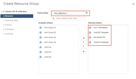
![]() Entire datastores can be backed up by selecting data center (for example, FlexPod-DC) in the parent entity list box and selecting/adding the datastore.
Entire datastores can be backed up by selecting data center (for example, FlexPod-DC) in the parent entity list box and selecting/adding the datastore.
8. From the Spanning Disks options, choose the Always include all spanning datastores option and click NEXT.
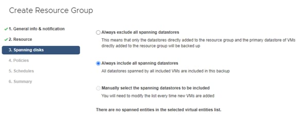
9. From the Policies tab, select the policy created in the last step to associate the policy with the resource group and click NEXT.
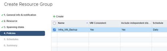
10. From Schedules, choose the schedule for the selected policy and click NEXT.
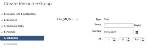
11. Review the summary and click FINISH to complete the creation of the resource group.
View Virtual Machine Backups using SnapCenter Plug-In
Backups of the virtual machines included in the resource group occurs according to the schedule of the policies associated with the resource group. To view the backups associated with each schedule, follow these steps:
1. Log into the VMware vCenter GUI.
2. Navigate to the VMs and Templates tab.
3. Select a VM that is the member of the previously created Resource Group.
4. Select the Configure tab.
5. Under SnapCenter Plug-in for vSphere, select the Backups tab to view all the backups available for the VM.
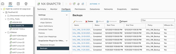
6. Navigate to Menu > SnapCenter Plug-in for VMware vSphere and select Dashboard to view recent job activity, backup jobs and configuration details.
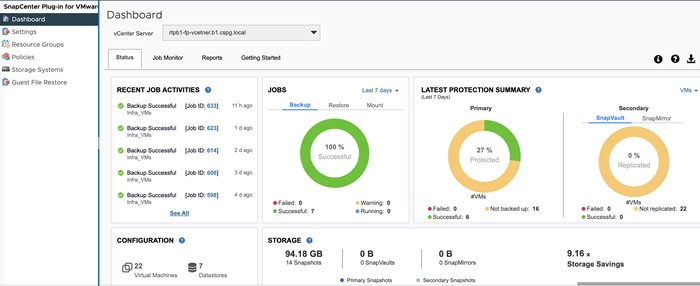
7. Click Resource Groups and select a resource group. In the right pane, the completed backups are displayed.
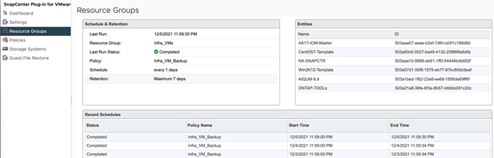
On-Demand Backup for a Resource Group
To create an on-demand backup for a resource group, follow these steps:
1. From the vCenter GUI, select Menu > SnapCenter Plugin for VMware vSphere.
2. Click Resource Groups.
3. Select a resource group and click Run Now to run the backup immediately.
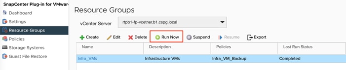
Restore a VM using SnapCenter Plug-In
To restore a VM from a SnapCenter backup, follow these steps:
![]() The SnapCenter Plug-in for VMware vSphere provides native backup, recovery, and cloning of virtualized applications.
The SnapCenter Plug-in for VMware vSphere provides native backup, recovery, and cloning of virtualized applications.
1. Log into VMware vCenter.
2. Navigate to VMs and Templates, select a VM and right-click to access the context menu. Select NetApp SnapCenter > Restore.
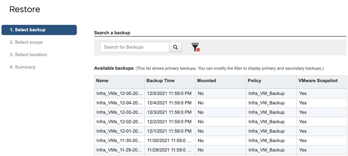
3. Select a backup to restore. Click NEXT.

4. From the Restore Scope drop-down list, select either Entire virtual machine to restore the virtual machine with all Virtual Machine Disks (VMDKs) or select Particular Virtual Disk to restore the VMDK without affecting the virtual machine configuration and other VMDKs.
5. Select the ESXi host that the VM should be restored to and check the box to restart the VM (if needed).
6. Click NEXT.
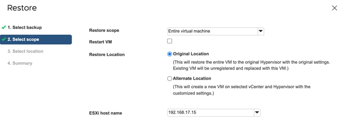
7. Select the destination datastore and click NEXT.
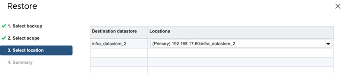
8. Review the Summary and click FINISH.
Active IQ Unified Manager 9.9P1 Installation
Active IQ Unified Manager enables customers to monitor and manage the health and performance of ONTAP storage systems and virtual infrastructure from a single interface. Unified Manager provides a graphical interface that displays the capacity, availability, protection, and performance status of the monitored storage systems. Active IQ Unified Manager is required to integrate NetApp storage with Cisco Intersight.
This section describes the steps to deploy NetApp Active IQ Unified Manager 9.9P1 as a virtual appliance. Table 22 lists the recommended configuration for the VM.
Table 22. Virtual Machine Configuration
| Hardware Configuration |
Recommended Settings |
| RAM |
12 GB |
| Processors |
4 CPUs |
| CPU Cycle Capacity |
9572 MHz total |
| Free Disk Space/virtual disk size |
5 GB - Thin provisioned 152 GB – Thick provisioned |
![]() There is a limit to the number of nodes that a single instance of Active IQ Unified Manager can monitor before a second instance of Active IQ Unified Manager is needed. See the Unified Manager Best Practices Guide (TR-4621) for more details.
There is a limit to the number of nodes that a single instance of Active IQ Unified Manager can monitor before a second instance of Active IQ Unified Manager is needed. See the Unified Manager Best Practices Guide (TR-4621) for more details.
Install NetApp Active IQ Unified Manager 9.9P1
To install Active IQ Unified Manager 9.9P1, follow these steps:
1. Download NetApp Active IQ Unified Manager for VMware vSphere OVA file from: https://mysupport.netapp.com/site/products/all/details/activeiq-unified-manager/downloads-tab.
2. In the VMware vCenter GUI, click VMs and Templates and then click Actions> Deploy OVF Template.
3. Specify the location of the OVF Template and click NEXT.
4. On the Select a name and folder page, enter a unique name for the VM, and select a deployment location, and then click NEXT.
5. On the Select a compute resource screen, select the cluster where VM will be deployed and click NEXT.
6. On the Review details page, verify the OVA template details and click NEXT.
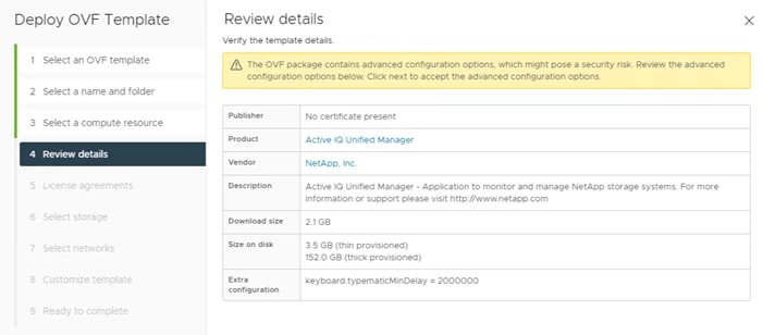
7. On the License agreements page, read and check the box for I accept all license agreements. Click NEXT.
8. On the Select storage page, select following parameters for the VM deployment:
a. Choose the disk format for the VMDKs (for example, Think Provisioning).
b. Choose a VM Storage Policy (for example, Datastore Default).
c. Choose a datastore to store the deployed OVA template (for example, infra_datastore_2).
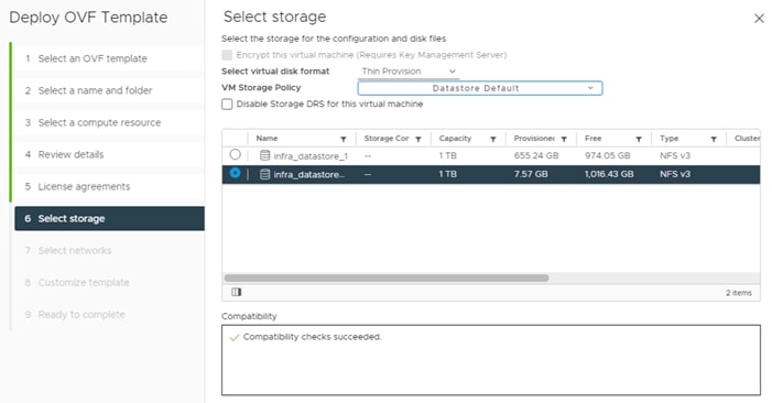
9. Click NEXT.
10. On the Select networks page, select the destination network (for example, IB-MGMT) and click NEXT.
11. On the Customize template page, provide network details such as hostname, IP address, gateway, and DNS.
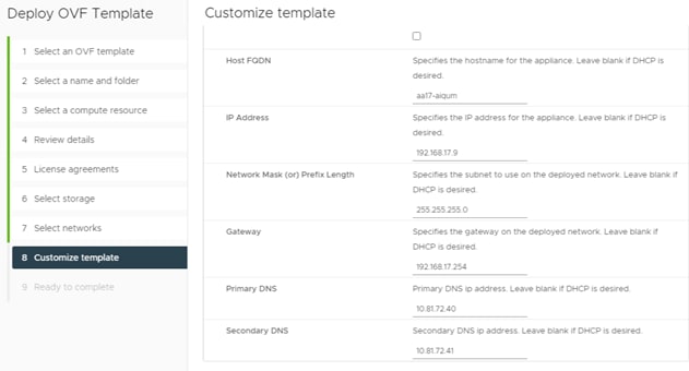
![]() Scroll through the customization template to ensure all required values are entered.
Scroll through the customization template to ensure all required values are entered.
12. Click NEXT.
13. On the Ready to complete page, review the settings and click FINISH. Wait for the VM deployment to complete before proceeding to the next step.
14. Select the newly created Active IQ Unified Manager VM, right-click and select Power > Power On.
15. While the virtual machine is powering on, click the prompt in the yellow banner to Install VMware tools.
![]() Because of timing, VMware tools might not install correctly. In that case VMware tools can be manually installed after Active IQ Unified Manager VM is up and running.
Because of timing, VMware tools might not install correctly. In that case VMware tools can be manually installed after Active IQ Unified Manager VM is up and running.
16. Open the VM console for the Active IQ Unified Manager VM and configure the time zone information when displayed.

17. Create a maintenance user account when prompted by specifying a user account name and password.
![]() Save the maintenance user account credentials in a secure location. These credentials will be used for the initial GUI login and to make any configuration changes to the appliance settings in future.
Save the maintenance user account credentials in a secure location. These credentials will be used for the initial GUI login and to make any configuration changes to the appliance settings in future.
![]() If the systems complaints about Network information not valid, enter the values for hostname, IP address and DNS information when prompted.
If the systems complaints about Network information not valid, enter the values for hostname, IP address and DNS information when prompted.
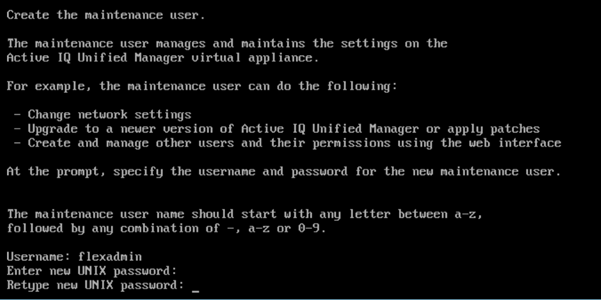
18. Log into NetApp Active IQ Unified Manager using the IP address or URL displayed on the deployment screen using the maintenance user credentials created in the last step.
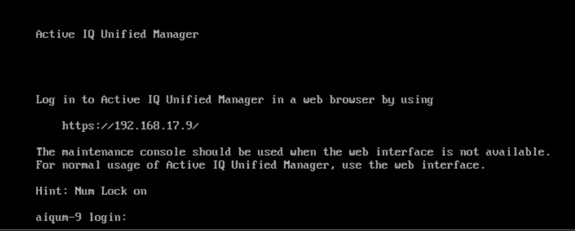
Configure Active IQ Unified Manager
Initial Setup
To configure Active IQ Unified Manager and to add a storage system, follow these steps:
1. Launch a web browser and log into Active IQ Unified Manger using the URL shown in the VM console.
2. Enter the email address that Unified Manager will use to send alerts and the mail server configuration. Click Continue.
3. Select Agree and Continue on the Set up AutoSupport configuration.
4. Check the box for Enable API Gateway and click Continue.
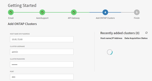
5. Enter the ONTAP cluster hostname or IP address and the admin login credentials.

6. Click Add.
7. Click Yes to trust the self-signed cluster certificate and finish adding the storage system.
![]() The initial discovery process can take up to 15 minutes to complete.
The initial discovery process can take up to 15 minutes to complete.
Review Security Compliance with Active IQ Unified Manager
Active IQ Unified Manager identifies issues and makes recommendations to improve the security posture of ONTAP. Active IQ Unified Manager evaluates ONTAP storage based on recommendations made in the Security Hardening Guide for ONTAP 9. Items are identified according to their level of compliance with the recommendations. Review the Security Hardening Guide for NetApp ONTAP 9 (TR-4569) for additional information and recommendations for securing ONTAP 9.
![]() All events identified do not inherently apply to all environments, for example, FIPS compliance.
All events identified do not inherently apply to all environments, for example, FIPS compliance.
![]()
To identify security events in Active IQ Unified Manager, follow these steps:
1. Navigate to the URL of the Active IQ Unified Manager and login.
2. Select the Dashboard from the left menu bar in Active IQ Unified Manager.
3. Locate the Security card and note the compliance level of the cluster and SVM.
4. Click the blue arrow to expand the findings.
5. Locate Individual Cluster section and the Cluster Compliance card. From the drop-down list select View All.
6. Select an event from the list and click the name of the event to view the remediation steps.
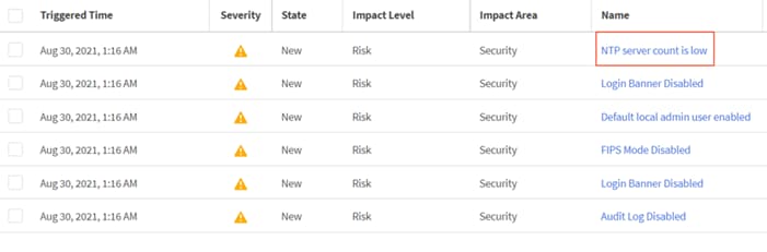
7. Remediate the risk if applicable to current environment and perform the suggested actions to fix the issue.
Remediate Security Compliance Findings
Active IQ identifies several security compliance risks after installation that can be immediately corrected to improve the security posture of ONTAP. Some of easy to mitigate examples are covered here.
Correct Cluster Risks
To correct cluster risks, follow these steps:
1. To associate an additional NTP server with the cluster, run the ONTAP command:
cluster time-service ntp server create -server <ntp server host name or ip address>
2. Enable the login banner on the cluster:
security login banner modify -vserver <clustername> -message "Access restricted to authorized users"
Deploy Cisco Intersight Assist Appliance
Cisco Intersight works with NetApp’s ONTAP storage and VMware vCenter using third-party device connectors. Since third-party infrastructure does not contain any built-in Intersight device connector, Cisco Intersight Assist virtual appliance enables Cisco Intersight to communicate with non-Cisco devices.
![]() A single Cisco Intersight Assist virtual appliance can support both NetApp ONTAP storage and VMware vCenter.
A single Cisco Intersight Assist virtual appliance can support both NetApp ONTAP storage and VMware vCenter.
Figure 3. Managing NetApp and VMware vCenter through Cisco Intersight using Intersight Assist
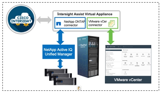
To install Intersight Assist from an Open Virtual Appliance (OVA), download the latest release of the Cisco Intersight Virtual Appliance for vSphere OVA from https://software.cisco.com/download/home/286319499/type/286323047/release/1.0.9-342?catid=268439477
Set up DNS entries
Setting up Cisco Intersight Virtual Appliance requires an IP address and 2 hostnames for that IP address. The hostnames must be in the following formats:
myhost.mydomain.com: A hostname in this format is used to access the GUI. This must be defined as an A record and PTR record in DNS. The PTR record is required for reverse lookup of the IP address. If an IP address resolves to multiple hostnames, the first one in the list is used.
dc-myhost.mydomain.com: The dc- must be prepended to your hostname. This hostname must be defined as the CNAME of myhost.mydomain.com. Hostnames in this format are used internally by the appliance to manage device connections.
In this lab deployment following information was used to deploy an Intersight Assist VM:
● Hostname: rtpb1-assist-1.b1.cspg.local
● IP address: 10.81.72.99
● DNS Entries (Windows AD/DNS):
◦ A Record
![]()
◦ CNAME:
![]()
◦ PTR (reverse lookup):
![]()
For more details, refer to https://www.cisco.com/c/en/us/td/docs/unified_computing/Intersight/b_Cisco_Intersight_Appliance_Getting_Started_Guide/b_Cisco_Intersight_Appliance_Install_and_Upgrade_Guide_chapter_00.html.
Deploy Intersight OVA
Ensure that the appropriate entries of type A, CNAME, and PTR records exist in the DNS, as covered in the last section. Proceed with following steps to deploy the Intersight Assist VM from OVA template.
1. Log into vCenter GUI and select Menu > Hosts and Clusters.
2. From Hosts and Clusters, right-click the cluster and click Deploy OVF Template.
3. Browse to the intersight-appliance-installer-vsphere-1.0.9-342.ova or the latest release file. Click NEXT.
4. Name the Intersight Assist VM and select the location. Click NEXT.
5. Choose the cluster and click NEXT.
6. Review details, click Ignore, and click NEXT.
7. Choose a deployment configuration. A deployment size of Tiny was used for this verification. Click NEXT.
8. Choose appropriate datastore (for example, infra_datastore_2) for storage and select the Thin Provision virtual disk format. Click NEXT.
9. Select appropriate management network for the VM Network. Click NEXT.
![]() The Intersight Assist VM must be able to access both the IB-MGMT network on FlexPod and Intersight.com. Select and configure the management network appropriately. If selecting IB-MGMT network on FlexPod, make sure routing and firewall is setup correctly to access Internet.
The Intersight Assist VM must be able to access both the IB-MGMT network on FlexPod and Intersight.com. Select and configure the management network appropriately. If selecting IB-MGMT network on FlexPod, make sure routing and firewall is setup correctly to access Internet.
10. Fill in all values to customize the template. Click NEXT.
11. Review the deployment information and click FINISH to deploy the appliance.
12. When the OVA deployment is complete, right-click the Intersight Assist VM and click Edit Settings.
13. Expand CPU and verify the socket configuration. For example, in the following deployment, on a 2-socket system, VM was configured for 8 sockets:
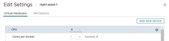
14. Adjust the Cores per Socket so that the number of Sockets matches the server CPU configuration (2 sockets in this deployment):
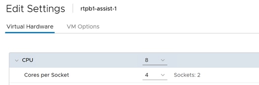
15. Click OK.
16. Right-click the Intersight Assist VM and select Power > Power On.
17. When the VM powers on and login prompt is visible (use remote console), connect to https://intersight-assist-fqdn.
![]() It may take a few minutes for https://intersight-assist-fqdn to respond.
It may take a few minutes for https://intersight-assist-fqdn to respond.
18. Navigate the security prompts and select Intersight Assist. Click Proceed.
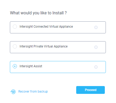
19. Cisco Intersight Assist VM needs to be claimed in Cisco Intersight using the Device ID and Claim Code information visible in the GUI.
20. Log into Cisco Intersight.
21. From Cisco Intersight, click ADMIN > Targets.
22. Click Claim Target. Select Cisco Intersight Assist and click Start.
23. Copy and paste the Device ID and Claim Code shown in the Intersight Assist web interface to the Cisco Intersight Device Claim window.
24. Select the Resource Group and click Claim.
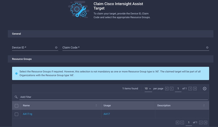
25. Intersight Assist will now appear as a claimed device.
26. In the Intersight Assist web interface, verify that Intersight Assist is Connected Successfully, and click Continue.
![]() The Intersight Assist software will now be downloaded and installed into the Intersight Assist VM. This can take up to an hour to complete.
The Intersight Assist software will now be downloaded and installed into the Intersight Assist VM. This can take up to an hour to complete.
27. When the software download is complete, an Intersight Assist login screen will appear.
28. Log into Intersight Assist with the admin user and the password supplied in the OVA installation. Check the Intersight Assist status and log out of Intersight Assist.
Claim VMware vCenter using Cisco Intersight Assist Appliance
To claim the vCenter from Cisco Intersight, follow these steps.
1. Log into Cisco Intersight.
2. Select ADMIN > Targets and click Claim Target.
3. In the Select Target Type window, select VMware vCenter under Hypervisor and click Start.
4. In the VMware vCenter window, verify Intersight Assist is correctly selected.
5. Fill in the vCenter information. If Intersight Workflow Optimizer (IWO) will be used, turn on Datastore Browsing Enabled and Guest Metrics Enabled. Click Claim.
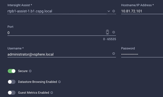
6. After a few minutes, the VMware vCenter will appear in the Devices list.
7. Detailed information obtained from the vCenter can now be viewed by clicking OPERATE > Virtualization from the left menu.
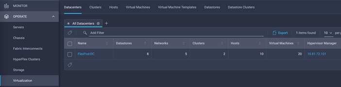
8. If Intersight Premier Licensing is enabled, VMware Virtualization workflows and tasks can be used under CONFIGURE > Orchestration.
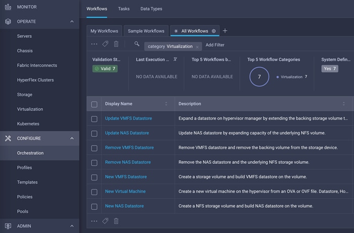
Interacting with Virtual Machines
VMware vCenter integration with Cisco Intersight allows customers to directly interact with the virtual machines (VMs) from the Cisco Intersight dashboard. In addition to obtaining in-depth information about a VM, including the operating system, CPU, memory, host name, and IP addresses assigned to the virtual machines, customers can use Intersight to perform following actions on the virtual machines:
● Launch VM console
● Power off
● Reset
● Shutdown guest OS
● Restart guest OS
● Suspend
To interact with Virtual Machines:
1. Log into Cisco Intersight.
2. Select OPERATE > Virtualization.
3. Click Virtual Machines in the main window.
4. Click “…” next to a VM and interact with various VM options
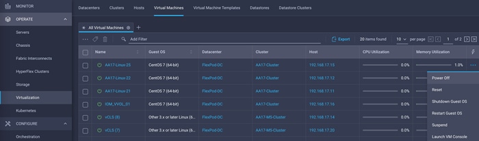
5. To gather more information about a VM, click a VM name. The same interactive options are available under Actions.
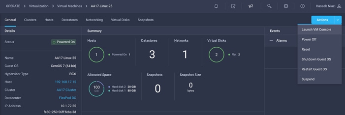
Claim NetApp Active IQ Manager using Cisco Intersight Assist Appliance
To claim the NetApp Active IQ Unified Manager, follow these steps.
1. Log into Cisco Intersight.
2. From Cisco Intersight, click ADMIN > Targets.
3. Click Claim a New Target. In the Select Target Type window, select NetApp Active IQ Unified Manager under Storage and click Start.
4. In the VMware vCenter window, verify Intersight Assist is correctly selected.
5. Fill in the NetApp Active IQ Unified Manager information and click Claim.
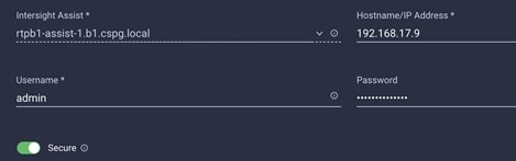
6. After a few minutes, the NetApp ONTAP Storage will appear in the OPERATE > Storage tab.
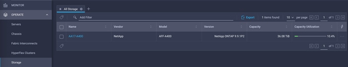
7. The storage dashboard widgets can also be viewed from MONITOR tab.
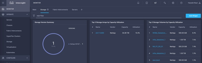
8. If Intersight Premier Licensing is enabled, storage workflows and tasks can be used under CONFIGURE > Orchestration.
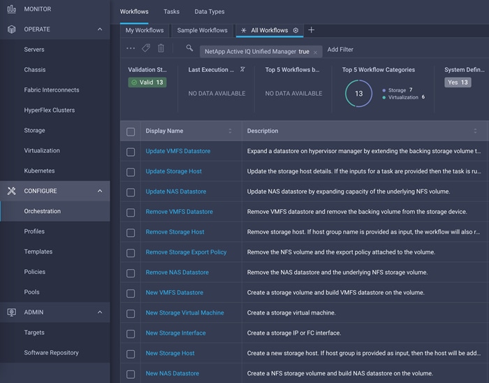
Executing Intersight Cloud Orchestrator Workflow
Cisco Intersight Orchestrator provides various workflows that can be used to automate VM and storage provisioning. This section covers executing a pre-defined sample workflow to manage datastore and associated storage on both ESXi and NetApp.
![]() Customers require Intersight Premier license to enable Intersight Orchestrator workflows and tasks.
Customers require Intersight Premier license to enable Intersight Orchestrator workflows and tasks.
Update NAS Datastore
This workflow allows customers to easily modify the size of an NFS datastore in their VMware environment. Customers need to identify an existing datastore in their vCenter and provide an updated size for the datastore. The workflow changes the size on the storage controller and triggers a rediscovery on all the ESXi hosts associated with the datastore. Customers do not need to log into vCenter or NetApp storage controller.
To execute the Update NAS Datastore workflow, follow these steps:
1. Log into Cisco Intersight.
2. Click Orchestration.
3. Click on Virtualization under Top 5 Workflow Categories to shortlist Virtualization Workflows.
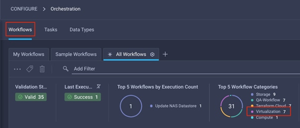
4. Click on Update NAS Datastore from the list.
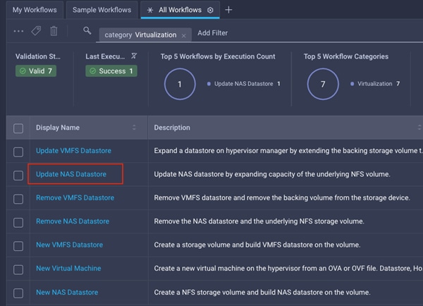
5. Click Execute on the bottom right of the screen
6. Click Select Organization (for example, AA17) from the drop-down list.
7. Click Select Hypervisor Manager and select the vCenter where datastore resides.
8. Click Select Datacenter to select the appropriate datacenter (for example, FlexPod-DC).
9. Click Select Cluster to select the appropriate Cluster (for example, AA17-Cluster).
10. Do not select a host to update all the ESXi hosts associated with the datastore.
11. Click Select Datastore to select a datastore that needs to be updated (for example, NX_NFS_DS_01). Currently the size of NX_NFS_DS_01 is 500GB. This size will be increased to 750GB.
AA17-A400::> volume show -vserver Infra-SVM -volume NX_NFS_DS_01 -fields size
vserver volume size
--------- ------------ -----
Infra-SVM NX_NFS_DS_01 500GB
12. Click Select Storage Device and select the NetApp controller (for example, AA17-A400).
13. Enter new Size (for example, 750) and select Unit from the drop-down list (for example, GiB).
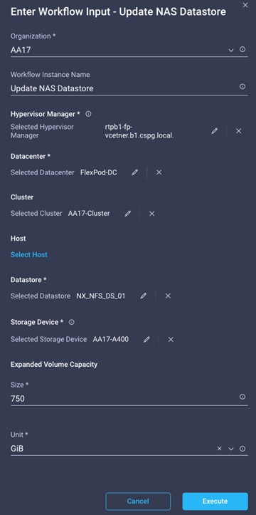
14. Click Execute.
15. The workflow will start executing and detailed execution information will appear on the screen. On successful execution of the workflow, the output on Intersight should look like:
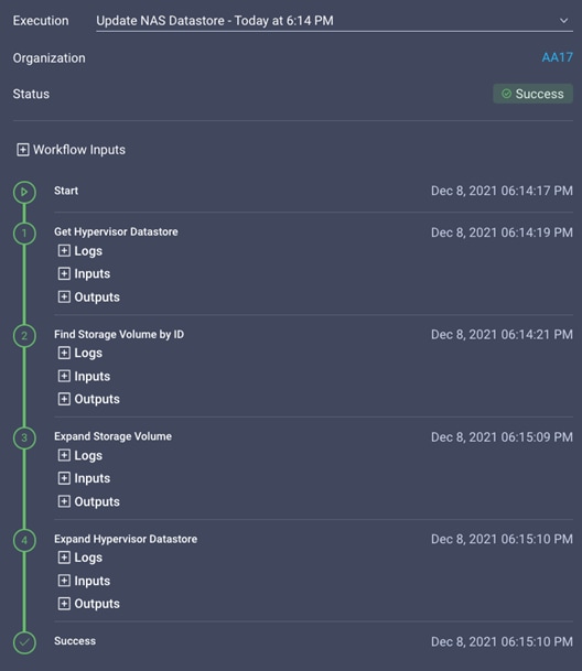
16. Log into vCenter and navigate to Menu > Storage to verify the datastore size:
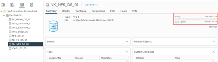
17. Verify the volume was updated on NetApp by logging into the NetApp ONTAP:
AA17-A400::> volume show -vserver Infra-SVM -volume NX_NFS_DS_01 -fields size
vserver volume size
--------- ------------ -----
Infra-SVM NX_NFS_DS_01 750GB
The features and functionality covered in this appendix are optional configurations which can be helpful in configuring and managing the FlexPod deployment.
Active IQ Unified Manager User Configuration
Add Local Users to Active IQ Unified Manager
To add a local user to Active IQ Unified Manager, follow these steps:
1. Navigate to Settings > General section and click Users.
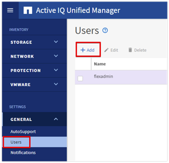
2. Click + Add and complete the requested information:
a. Choose Local User for the Type.
b. Enter a username and password.
c. Add the user’s email address.
d. Choose the appropriate role for the new user.
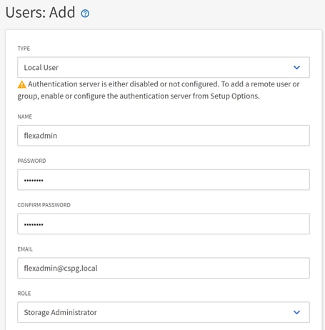
3. Click SAVE to finish adding the new user.
Configure Remote Authentication
Simplify user management and authentication for Active IQ Unified Manager by integrating it with Microsoft Active Directory. To connect Active IQ Unified Manager to Active Directory and perform user authentication with the Active Directory domain, follow these steps:
![]() You must be logged on as the maintenance user created during the installation or another user with Application Administrator privileges to configure remote authentication.
You must be logged on as the maintenance user created during the installation or another user with Application Administrator privileges to configure remote authentication.
1. Navigate to the General and select Remote Authentication.
2. Select the option to enable Remote Authentication and define a remote user or remote group.
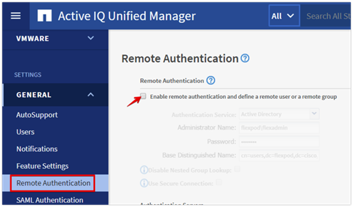
3. Select Active Directory from the authentication service list.
4. Enter the Active Directory service account name and password. The account name can be in the format of domain\user or user@domain.
5. Enter the base DN where your Active Directory users reside.
6. If Active Directory LDAP communications are protected via SSL enable the Use Secure Connection option.
7. Add one or more Active Directory domain controllers by clicking Add and entering the IP or FQDN of the domain controller.
8. Click Save to enable the configuration.
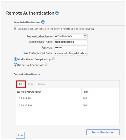
9. Click Test Authentication and enter an Active Directory username and password to test authentication with the Active Directory authentication servers. Click Start.
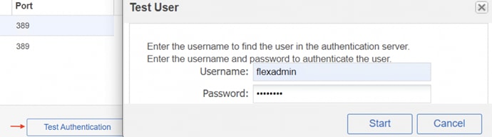
A result message displays indicating authentication was successful:
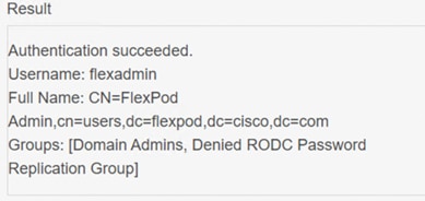
Add a Remote User to Active IQ Unified Manager
To add remote users that need to access Active IQ Unified Manager and authenticate with the Active Directory servers, follow these steps:
1. Navigate to the General section and select Users.
2. Click Add and select Remote User from the Type drop-down list.
3. Enter the following information into the form:
a. The username of the Active Directory user.
b. Email address of the user.
c. Choose the appropriate role for the user
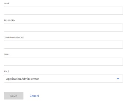
4. Click Save to add the remote user to Active IQ Unified Manager.
Active IQ Unified Manager vCenter Configuration
Active IQ Unified Manager provides visibility into vCenter and the virtual machines running inside the datastores backed by ONTAP storage. Virtual machines and storage are monitored to enable quick identification of performance issues within the various components of the virtual infrastructure stack.
Before adding vCenter into Active IQ Unified Manager, the log level of the vCenter server must be changed using following steps:
1. In the vSphere client navigate to Menu > VMs and Templates and select the vCenter instance from the top of the object tree.
2. Click the Configure tab, expand Settings, and select General.
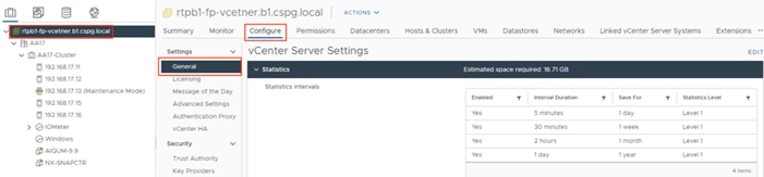
3. Click EDIT.
4. In the pop-up window under Statistics, locate the 5 minutes Interval Duration row and change the setting to Level 3 under the Statistics Level column.
5. Click SAVE.
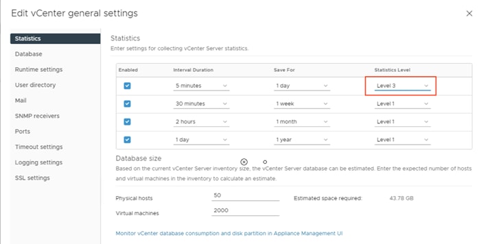
6. Switch to the Active IQ Unified Manager and navigate to the VMware section located under Inventory.
7. Expand VMware and select vCenter.
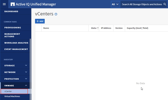
8. Click Add.
9. Enter the VMware vCenter server details and click Save.
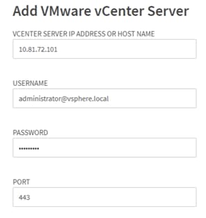
10. A dialog box will appear asking to authorize the certificate. Click Yes to accept the certificate and add the vCenter server.
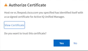
![]() It may take up to 15 minutes to discover vCenter. Performance data can take up to an hour to become available.
It may take up to 15 minutes to discover vCenter. Performance data can take up to an hour to become available.
View Virtual Machine Inventory
The virtual machine inventory is automatically added to Active IQ Unified Manager during discovery of the vCenter server. Virtual machines can be viewed in a hierarchical display detailing storage capacity, IOPS and latency for each component in the virtual infrastructure to troubleshoot the source of any performance related issues.
To review the virtual machine topology and statistics, follow these steps:
1. Log into NetApp Active IQ Unified Manager.
2. Navigate to the VMware section located under Inventory, expand the section, and click Virtual Machines.
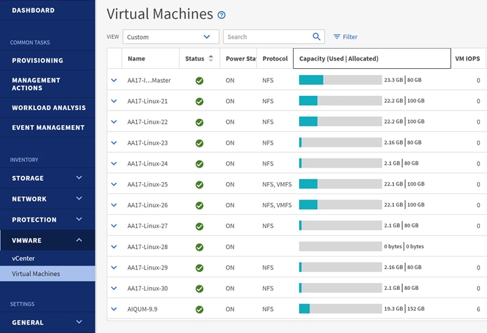
3. Select a VM and click the blue caret to expose the topology view. Review the compute, network, and storage components and their associated IOPS and latency statistics.
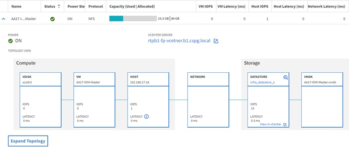
4. Click Expand Topology to see the entire hierarchy of the virtual machine and its virtual disks as it is connected through the virtual infrastructure stack. The VM components are mapped from vSphere and compute through the network to the storage.
NetApp Active IQ is a data-driven service that leverages artificial intelligence and machine learning to provide analytics and actionable intelligence for ONTAP storage systems. Active IQ uses AutoSupport data to deliver proactive guidance and best practices recommendations to optimize storage performance and minimize risk. Additional Active IQ documentation is available on the Active IQ Documentation Resources web page.
Active IQ is automatically enabled when AutoSupport is configured on the NetApp ONTAP storage controllers. To get started with Active IQ, follow these steps:
1. Navigate to the Active IQ portal at https://activeiq.netapp.com/
2. Login with NetApp support account ID
3. At the welcome screen enter the cluster name or one of controller serial numbers in the search box. Active IQ will automatically begin searching for the cluster and display results below.

4. Click the <cluster name> (for example, aa16-a400) to launch the main dashboard.
Add a Watchlist to the Discovery Dashboard
The system level dashboard is the default view for systems in Active IQ. To create a watchlist for the quick access cluster to cluster health and risk information, follow these steps:
1. Click GENERAL > Watch List in the left menu bar.
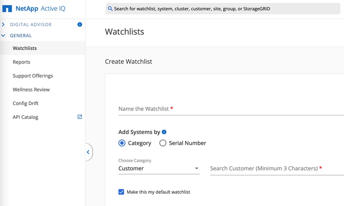
2. Enter a name for the watchlist.
3. Select the radio button to add systems by serial number and enter the cluster serial numbers to the watchlist.
4. Check the box for Make this my default watchlist if desired.
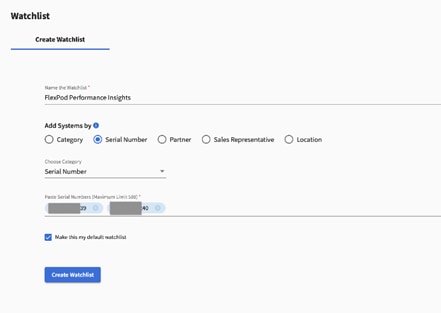
5. Click Create Watchlist.
6. Click Manage watchlists and then click the ellipsis on the cluster watchlist card.
7. Select View in Discovery Dashboard.
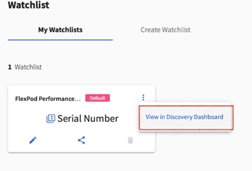
8. View the health and risk overview for the cluster.
Create Active IQ Digital Advisor Dashboard
The Active IQ Digital advisor provides a summary dashboard and system wellness score based on the health and risks that Active IQ has identified. The dashboard provides a quick way to identify and get proactive recommendations on how to mitigate risks in the storage environment including links to technical reports and mitigation plans.
To create an Active IQ Digital Advisor dashboard, follow these steps:
1. At the cluster dashboard, click Active IQ Digital Advisor from the top menu.
2. Select the watchlist created in the previous step and click Next.
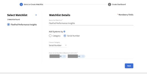
3. Accept the dashboard default name and select all the available widgets.
4. Check the box Make this the default dashboard and click Create.
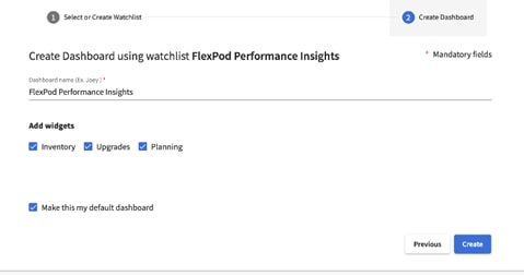
5. Review the enhanced dashboard including the Wellness Score and any recommended actions or risks.
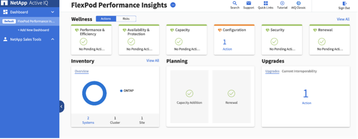
6. Switch between the Actions and Risks tabs to view the risks by category or a list of all risks with their impact and links to corrective actions.
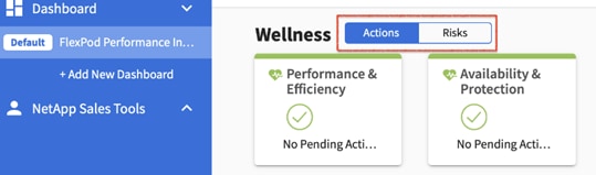
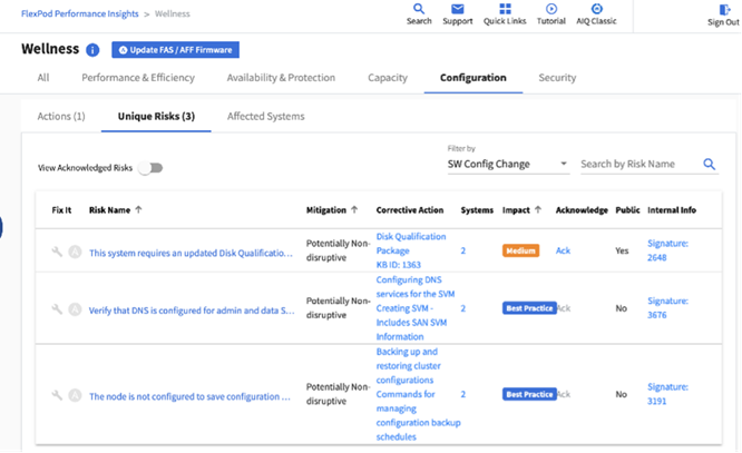
7. Click the links in the Corrective Action column to read the bug information or knowledge base article about how to remediate the risk.
![]() Additional tutorials and video walk-throughs of Active IQ features can be viewed on the following page: https://docs.netapp.com/us-en/active-iq/
Additional tutorials and video walk-throughs of Active IQ features can be viewed on the following page: https://docs.netapp.com/us-en/active-iq/
FlexPod Backups
Cisco Intersight SaaS Platform
Cisco Intersight SaaS platform maintains customer configurations online. No separate backup was created for UCS configuration.
Cisco Nexus and MDS Backups
The configuration of the Cisco Nexus 9000 and Cisco MDS 9132T switches can be backed up manually at any time with the copy command, but automated backups can be enabled using the NX-OS feature scheduler.
An example of setting up automated configuration backups of one of the NX-OS switches is shown below:
feature scheduler
scheduler logfile size 1024
scheduler job name backup-cfg
copy running-config tftp://<server-ip>/$(SWITCHNAME)-cfg.$(TIMESTAMP) vrf management
exit
scheduler schedule name daily
job name backup-cfg
time daily 2:00
end
![]() Use of “vrf management” in the copy command is only needed when Mgmt0 interface is part of VRF management.
Use of “vrf management” in the copy command is only needed when Mgmt0 interface is part of VRF management.
Verify the scheduler job has been correctly setup using following command(s):
show scheduler job
Job Name: backup-cfg
--------------------
copy running-config tftp://10.1.156.150/$(SWITCHNAME)-cfg.$(TIMESTAMP) vrf management
==============================================================================
show scheduler schedule
Schedule Name : daily
---------------------------
User Name : admin
Schedule Type : Run every day at 2 Hrs 0 Mins
Last Execution Time : Yet to be executed
-----------------------------------------------
Job Name Last Execution Status
-----------------------------------------------
backup-cfg -NA-
==============================================================================
The documentation for the feature scheduler can be found here: https://www.cisco.com/c/en/us/td/docs/switches/datacenter/nexus9000/sw/93x/system-management/b-cisco-nexus-9000-series-nx-os-system-management-configuration-guide-93x/b-cisco-nexus-9000-series-nx-os-system-management-configuration-guide-93x_chapter_0100001.html
Basic scheduled backup for the vCenter Server Appliance is available within the native capabilities of the VCSA. To create a scheduled backup, follow these steps:
1. Connect to the VCSA Console at https://<VCSA IP>:5480.
2. Log in as root.
3. Click Backup in the list to open the Backup Schedule Dialogue.
4. To the right of Backup Schedule, click CONFIGURE.
5. Specify:
a. The Backup location with the protocol to use (FTPS,HTTPS,SFTP,FTP,NFS,SMB, and HTTP)
b. The Username and Password. For the NFS (NFS3) example captured below, the username is root and use a random password because NFSv3 sys security was configured.
c. The Number of backups to retain.
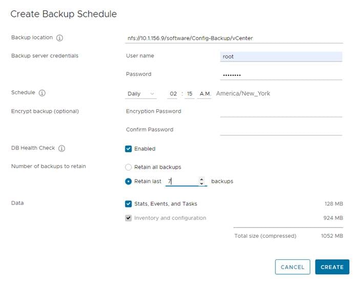
6. Click CREATE.
![]() The Backup Schedule Status should now show Enabled.
The Backup Schedule Status should now show Enabled.
7. To test the backup setup, select BACKUP NOW and select “Use backup location and user name from backup schedule” to test the backup location.
8. Restoration can be initiated with the backed-up files using the Restore function of the VCSA 7.0 Installer.
Haseeb Niazi, Principal Technical Marketing Engineer, Cisco Systems, Inc.
Haseeb Niazi is a Principal Technical Marketing Engineer (TME) in Cisco UCS Solutions group and has over 22 years of experience at Cisco in the data center, security, enterprise, and service provider solutions and technologies. As a member of various solution and services teams, Haseeb has helped many enterprise and service provider customers evaluate and deploy a wide variety of Cisco products and solutions. As a TME at UCS Solutions group, Haseeb focuses on network, compute, virtualization, storage, automation, and orchestration aspects of various converged infrastructure stacks. Haseeb holds a master's degree in computer engineering from the University of Southern California and is a Cisco Certified Internetwork Expert (CCIE 7848).
Jyh-shing Chen, Technical Marketing Engineer, Hybrid Cloud Infra & OEM Solutions, NetApp
Jyh-shing is currently focusing on FlexPod hybrid cloud infrastructure solution design, implementation validation, management automation, and sales enablement. Jyh-shing joined NetApp in 2006 and had previously worked on Solaris and VMware interoperability and integration projects, and qualification projects on ONTAP MetroCluster solutions and Cloud Volumes data services. Before joining NetApp, Jyh-shing’s engineering experiences include software and firmware development on cardiology health imaging system, mass spectrometer system, Fibre Channel virtual tape library, and the research and development of microfluidic devices. Jyh-shing holds B.S. and M.S. degrees from National Taiwan University, a PhD degree in Mechanical Engineering from MIT, and an MBA degree from Meredith College
For their support and contribution to the design, validation, and creation of this Cisco Validated Design, the authors would like to thank:
● John George, Technical Marketing Engineer, Cisco Systems, Inc.
● Arvind Ramakrishnan, Sr. Technical Marketing Engineer, NetApp
● Kamini Singh, Technical Marketing Engineer, NetApp
For comments and suggestions about this guide and related guides, join the discussion on Cisco Community at https://cs.co/en-cvds.