FlexPod Datacenter with Cisco ACI 3.0 and Microsoft Hyper-V Windows Server 2016 Design Guide
Available Languages

FlexPod Datacenter with Cisco ACI 3.0 and Microsoft Hyper-V Windows Server 2016 Design Guide
Last Updated: January 31, 2018
About the Cisco Validated Design Program
The Cisco Validated Design (CVD) program consists of systems and solutions designed, tested, and documented to facilitate faster, more reliable, and more predictable customer deployments. For more information visit:
http://www.cisco.com/go/designzone
ALL DESIGNS, SPECIFICATIONS, STATEMENTS, INFORMATION, AND RECOMMENDATIONS (COLLECTIVELY, "DESIGNS") IN THIS MANUAL ARE PRESENTED "AS IS," WITH ALL FAULTS. CISCO AND ITS SUPPLIERS DISCLAIM ALL WARRANTIES, INCLUDING, WITHOUT LIMITATION, THE WARRANTY OF MERCHANTABILITY, FITNESS FOR A PARTICULAR PURPOSE AND NONINFRINGEMENT OR ARISING FROM A COURSE OF DEALING, USAGE, OR TRADE PRACTICE. IN NO EVENT SHALL CISCO OR ITS SUPPLIERS BE LIABLE FOR ANY INDIRECT, SPECIAL, CONSEQUENTIAL, OR INCIDENTAL DAMAGES, INCLUDING, WITHOUT LIMITATION, LOST PROFITS OR LOSS OR DAMAGE TO DATA ARISING OUT OF THE USE OR INABILITY TO USE THE DESIGNS, EVEN IF CISCO OR ITS SUPPLIERS HAVE BEEN ADVISED OF THE POSSIBILITY OF SUCH DAMAGES.
THE DESIGNS ARE SUBJECT TO CHANGE WITHOUT NOTICE. USERS ARE SOLELY RESPONSIBLE FOR THEIR APPLICATION OF THE DESIGNS. THE DESIGNS DO NOT CONSTITUTE THE TECHNICAL OR OTHER PROFESSIONAL ADVICE OF CISCO, ITS SUPPLIERS OR PARTNERS. USERS SHOULD CONSULT THEIR OWN TECHNICAL ADVISORS BEFORE IMPLEMENTING THE DESIGNS. RESULTS MAY VARY DEPENDING ON FACTORS NOT TESTED BY CISCO.
CCDE, CCENT, Cisco Eos, Cisco Lumin, Cisco Nexus, Cisco StadiumVision, Cisco TelePresence, Cisco WebEx, the Cisco logo, DCE, and Welcome to the Human Network are trademarks; Changing the Way We Work, Live, Play, and Learn and Cisco Store are service marks; and Access Registrar, Aironet, AsyncOS, Bringing the Meeting To You, Catalyst, CCDA, CCDP, CCIE, CCIP, CCNA, CCNP, CCSP, CCVP, Cisco, the Cisco Certified Internetwork Expert logo, Cisco IOS, Cisco Press, Cisco Systems, Cisco Systems Capital, the Cisco Systems logo, Cisco Unified Computing System (Cisco UCS), Cisco UCS B-Series Blade Servers, Cisco UCS C-Series Rack Servers, Cisco UCS S-Series Storage Servers, Cisco UCS Manager, Cisco UCS Management Software, Cisco Unified Fabric, Cisco Application Centric Infrastructure, Cisco Nexus 9000 Series, Cisco Nexus 7000 Series. Cisco Prime Data Center Network Manager, Cisco NX-OS Software, Cisco MDS Series, Cisco Unity, Collaboration Without Limitation, EtherFast, EtherSwitch, Event Center, Fast Step, Follow Me Browsing, FormShare, GigaDrive, HomeLink, Internet Quotient, IOS, iPhone, iQuick Study, LightStream, Linksys, MediaTone, MeetingPlace, MeetingPlace Chime Sound, MGX, Networkers, Networking Academy, Network Registrar, PCNow, PIX, PowerPanels, ProConnect, ScriptShare, SenderBase, SMARTnet, Spectrum Expert, StackWise, The Fastest Way to Increase Your Internet Quotient, TransPath, WebEx, and the WebEx logo are registered trademarks of Cisco Systems, Inc. and/or its affiliates in the United States and certain other countries.
All other trademarks mentioned in this document or website are the property of their respective owners. The use of the word partner does not imply a partnership relationship between Cisco and any other company. (0809R)
© 2018 Cisco Systems, Inc. All rights reserved.
Table of Contents
FlexPod and Application Centric Infrastructure
FlexPod with Cisco ACI—Components
Validated System Hardware Components
NetApp All-Flash FAS (AFF) A-Series Design
SMB vs SAN for Virtual Machine Disks
Application Centric Infrastructure (ACI) Design
End Point Group (EPG) Mapping in a FlexPod Environment
Onboarding Infrastructure Services
Onboarding a 3-Tier Application
Core Services and Storage Management
FlexPod Connectivity to Existing Infrastructure (Shared Layer 3 Out)
Cisco Unified Computing System
Cisco UCS 6300 Fabric Interconnects
Cisco UCS Design Options within this FlexPod
Microsoft System Center 2016 Virtual Machine Manager
Microsoft System Center 2016 Operation Manager
Cisco UCS Management and Microsoft System Center Integration
Management and Best Practices with Windows 2016 Hyper-V
System Center Virtual Machine Manager (SCVMM)
NetApp OnCommand Plug-in for Microsoft
OnCommand Workflow Automation Pack for ACI
Validated Hardware and Software
Cisco Validated Designs consist of systems and solutions that are designed, tested, and documented to facilitate and improve customer deployments. These designs incorporate a wide range of technologies and products into a portfolio of solutions that have been developed to address the business needs of our customers.
This document describes the Cisco and NetApp® FlexPod® solution, which is a validated approach for deploying Cisco and NetApp technologies as shared cloud infrastructure. This validated design provides a framework for deploying Microsoft Windows Hyper-V, a popular virtualization platform in enterprise class data centers, on FlexPod.
FlexPod is a leading integrated infrastructure supporting a broad range of enterprise workloads and use cases. This solution enables customers to quickly and reliably deploy Microsoft Windows Hyper-V based private cloud on integrated infrastructure.
The recommended solution architecture is built on Cisco UCS using the unified software release to support the Cisco UCS hardware platforms including Cisco UCS B-Series Blade Servers and Cisco UCS C-Series Rack-Mount Servers, Cisco UCS 6300 or 6200 Fabric Interconnects, Cisco Nexus 9000 Series Switches, and NetApp All Flash series storage arrays. In addition to that, it includes Microsoft Windows Hyper-V 2016, which provides a number of new features for optimizing storage utilization and facilitating private cloud.
Cisco and NetApp® have carefully validated and verified the FlexPod solution architecture and its many use cases while creating a portfolio of detailed documentation, information, and references to assist customers in transforming their data centers to this shared infrastructure model. This portfolio includes, but is not limited to the following items:
· Best practice architectural design
· Workload sizing and scaling guidance
· Implementation and deployment instructions
· Technical specifications (rules for what is a FlexPod® configuration)
· Frequently asked questions and answers (FAQs)
· Cisco Validated Designs (CVDs) and NetApp Validated Architectures (NVAs) covering a variety of use cases
Cisco and NetApp have also built a robust and experienced support team focused on FlexPod solutions, from customer account and technical sales representatives to professional services and technical support engineers. The support alliance between NetApp and Cisco gives customers and channel services partners direct access to technical experts who collaborate with cross vendors and have access to shared lab resources to resolve potential issues.
FlexPod supports tight integration with virtualized and cloud infrastructures, making it the logical choice for long-term investment. FlexPod also provides a uniform approach to IT architecture, offering a well-characterized and documented shared pool of resources for application workloads. FlexPod delivers operational efficiency and consistency with the versatility to meet a variety of SLAs and IT initiatives, including:
· Application rollouts or application migrations
· Business continuity and disaster recovery
· Desktop virtualization
· Cloud delivery models (public, private, hybrid) and service models (IaaS, PaaS, SaaS)
· Asset consolidation and virtualization
Introduction
Industry trends indicate a vast data center transformation toward shared infrastructure and cloud computing. Business agility requires application agility, so IT teams need to provision applications quickly and resources need to be able to scale up (or down) in minutes.
FlexPod Datacenter is a best practice data center architecture, designed and validated by Cisco and NetApp to meet the needs of enterprise customers and service providers. FlexPod Datacenter is built on NetApp All Flash FAS, Cisco Unified Computing System (UCS), and the Cisco Nexus family of switches. These components combine to enable management synergies across all of a business’s IT infrastructure. FlexPod Datacenter has been proven to be the optimal platform for virtualization and workload consolidation, enabling enterprises to standardize all of their IT infrastructure.
To simplify the evolution to a shared cloud infrastructure based on an application driven policy model, Cisco and NetApp have developed this solution called Microsoft Windows Hyper-V 2016 on FlexPod with Cisco Application Centric Infrastructure (ACI). Cisco ACI in the data center is a holistic architecture with centralized automation and policy-driven application profiles that delivers software flexibility with hardware performance.
Audience
The audience for this document includes, but is not limited to; sales engineers, field consultants, professional services, IT managers, partner engineers, and customers who want to take advantage of an infrastructure built to deliver IT efficiency and enable IT innovation.
Changes in FlexPod
The following design elements distinguish this version of FlexPod from previous models:
· Validation of Cisco ACI 3.0 with a NetApp All Flash FAS storage array
· Validation of the Cisco ACI 3.0 Release on Cisco Nexus 9000 Series Switches
· Support for the Cisco UCS 3.2 release and Cisco UCS B200-M5 servers
· Support for the latest release of NetApp Data ONTAP® 9.1
· A storage design supporting both SMB datastores and iSCSI and Fibre Channel SAN LUNs
· Support for FC/FCoE storage directly to the Cisco UCS Fabric Interconnect
· Application design guidance for multi-tiered applications using Cisco ACI application profiles and policies
FlexPod System Overview
FlexPod is a best practice datacenter architecture that includes the following components:
· Cisco Unified Computing System (Cisco UCS)
· Cisco Nexus switches
· Cisco MDS switches
· NetApp All Flash FAS (AFF) systems
Figure 1FlexPod Component Families
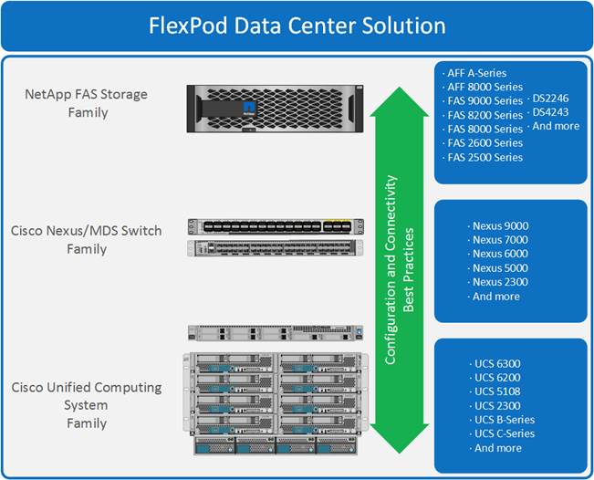
These components are connected and configured according to the best practices of both Cisco and NetApp to provide an ideal platform for running a variety of enterprise workloads with confidence. FlexPod can scale up for greater performance and capacity (adding compute, network, or storage resources individually as needed), or it can scale out for environments that require multiple consistent deployments (such as rolling out of additional FlexPod stacks). The reference architecture covered in this document leverages Cisco Nexus 9000 for the network switching element.
One of the key benefits of FlexPod is its ability to maintain consistency during scale. Each of the component families shown (Cisco UCS, Cisco Nexus, and NetApp AFF) offers platform and resource options to scale the infrastructure up or down, while supporting the same features and functionality that are required under the configuration and connectivity best practices of FlexPod.
FlexPod Design Principles
FlexPod addresses four primary design principles: scalability, flexibility, availability, and manageability. These architecture goals are as follows:
· Application availability. Makes sure that services are accessible and ready to use.
· Scalability. Addresses increasing demands with appropriate resources.
· Flexibility. Provides new services or recovers resources without requiring infrastructure modification.
· Manageability. Facilitates efficient infrastructure operations through open standards and APIs.
![]() Note: Performance is a key design criterion that is not directly addressed in this document. It has been addressed in other collateral, benchmarking, and solution testing efforts; this design guide validates the functionality.
Note: Performance is a key design criterion that is not directly addressed in this document. It has been addressed in other collateral, benchmarking, and solution testing efforts; this design guide validates the functionality.
FlexPod and Application Centric Infrastructure
The Cisco Nexus 9000 family of switches supports two modes of operation: NxOS standalone mode and Application Centric Infrastructure (ACI) fabric mode. In standalone mode, the switch performs as a typical Nexus switch with increased port density, low latency and 40G/100G connectivity. In fabric mode, the administrator can take advantage of Cisco ACI. Cisco Nexus 9000-based FlexPod design with Cisco ACI consists of Cisco Nexus 9500 and 9300 based spine/leaf switching architecture controlled using a cluster of three Application Policy Infrastructure Controllers (APICs).
Cisco ACI delivers a resilient fabric to satisfy today's dynamic applications. ACI leverages a network fabric that employs industry proven protocols coupled with innovative technologies to create a flexible, scalable, and highly available architecture of low-latency, high-bandwidth links. This fabric delivers application instantiations using profiles that house the requisite characteristics to enable end-to-end connectivity.
The ACI fabric is designed to support the industry trends of management automation, programmatic policies, and dynamic workload provisioning. The ACI fabric accomplishes this with a combination of hardware, policy-based control systems, and closely coupled software to provide advantages not possible in other architectures.
Cisco ACI Fabric
The Cisco ACI fabric consists of three major components:
· The Application Policy Infrastructure Controller (APIC)
· Spine switches
· Leaf switches
The ACI switching architecture is presented in a leaf-and-spine topology where every leaf connects to every spine using 40G Ethernet interface(s). The ACI Fabric Architecture is illustrated in Figure 2.
Figure 2Cisco ACI Fabric Architecture
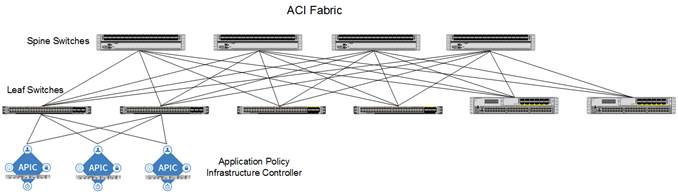
The software controller, APIC, is delivered as an appliance and three or more such appliances form a cluster for high availability and enhanced performance. APIC is responsible for all tasks enabling traffic transport including:
· Fabric activation
· Switch firmware management
· Network policy configuration and instantiation
Though the APIC acts as the centralized point of configuration for policy and network connectivity, it is never in line with the data path or the forwarding topology. The fabric can still forward traffic even when communication with the APIC is lost.
APIC provides both a command-line interface (CLI) and graphical-user interface (GUI) to configure and control the ACI fabric. APIC also exposes a northbound API through XML and JavaScript Object Notation (JSON) and an open source southbound API.
FlexPod with Cisco ACI—Components
FlexPod with ACI is designed to be fully redundant in the compute, network, and storage layers. There is no single point of failure from a device or traffic path perspective. Figure 3 shows how the various elements are connected together.
Figure 3FlexPod Design with Cisco ACI and NetApp Clustered Data ONTAP
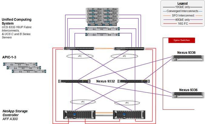
Fabric: As in the previous designs of FlexPod, link aggregation technologies play an important role in FlexPod with ACI providing improved aggregate bandwidth and link resiliency across the solution stack. The NetApp storage controllers, Cisco Unified Computing System, and Cisco Nexus 9000 platforms support active port channeling using 802.3ad standard Link Aggregation Control Protocol (LACP). Port channeling is a link aggregation technique offering link fault tolerance and traffic distribution (load balancing) for improved aggregate bandwidth across member ports. In addition, the Cisco Nexus 9000 series features virtual Port Channel (vPC) capabilities. vPC allows links that are physically connected to two different Cisco Nexus 9000 Series devices to appear as a single "logical" port channel to a third device, essentially offering device fault tolerance.
![]() Note: As shown in Figure 3, the vPC peer links are no longer needed. The peer link is handled in the leaf-to-spine connections and any two leaves in an ACI fabric can be paired in a vPC.
Note: As shown in Figure 3, the vPC peer links are no longer needed. The peer link is handled in the leaf-to-spine connections and any two leaves in an ACI fabric can be paired in a vPC.
The Cisco UCS Fabric Interconnects and NetApp FAS controllers benefit from the Cisco Nexus vPC abstraction, gaining link and device resiliency as well as full utilization of a non-blocking Ethernet fabric. Direct Fiber Channel (FC) connectivity between the storage controllers and Cisco UCS fabric interconnects is also shown here. This configuration is covered in the appendix of the FlexPod Datacenter with Microsoft Windows Hyper-V Server 2016 and Cisco ACI 3.0 deployment guide and provides FC SAN boot and FC application LUN connectivity. FCoE connectivity is also supported, but not covered in this document. Zoning is done in the fabric interconnects. The placement of Cisco MDS switches between storage and Cisco UCS is also supported, but is not covered in this document.
![]() Note: The FC connectivity does not pass through the ACI fabric and is not covered by ACI policy.
Note: The FC connectivity does not pass through the ACI fabric and is not covered by ACI policy.
Compute: Each Fabric Interconnect (FI) is connected to both the leaf switches and the links provide a robust 160GbE connection between the Cisco Unified Computing System and ACI fabric. Figure 4 illustrates the use of vPC enabled 40GbE uplinks between the Cisco Nexus 9000 leaf switches and Cisco UCS FI. Additional ports can be easily added to the design for increased bandwidth as needed. Each Cisco UCS 5108 chassis is connected to the FIs using a pair of ports from each IO Module for a combined 80G uplink to each FI. Current FlexPod design supports Cisco UCS C-Series connectivity both for direct attaching the Cisco UCS C-Series servers into the FIs at 40GE or 10GE or by connecting Cisco UCS C-Series to a supported Cisco Nexus Fabric Extender hanging off of the Cisco UCS FIs. FlexPod designs mandate Cisco UCS C-Series management using Cisco UCS Manager to provide a uniform look and feel across blade and standalone servers.
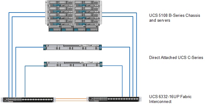
Storage: The ACI-based FlexPod design is an end-to-end IP-based storage solution that supports SAN access by using iSCSI. The solution provides a 40GbE fabric that is defined by Ethernet uplinks from the Cisco UCS Fabric Interconnects and NetApp storage devices connected to the Cisco Nexus switches. Optionally, the ACI-based FlexPod design can be configured for SAN boot or application LUN access by using Fibre Channel (FC) or Fibre Channel over Ethernet (FCoE). FC/FCoE access is provided by directly connecting the NetApp FAS controller to the Cisco UCS Fabric Interconnects as shown in Figure 5. Whether the access is FC or FCoE is determined by which port and SFP type is used on the storage controller and Fabric Interconnect.
![]() Note: The Cisco UCS server access to the Fabric Interconnect is always FCoE, but the connections to the storage controllers can be either FC or FCoE. Also note that although FC and FCoE are supported, only 16 Gb/s FC connections to storage are validated in this CVD.
Note: The Cisco UCS server access to the Fabric Interconnect is always FCoE, but the connections to the storage controllers can be either FC or FCoE. Also note that although FC and FCoE are supported, only 16 Gb/s FC connections to storage are validated in this CVD.
Figure 5FC Connectivity - Direct Attached SAN
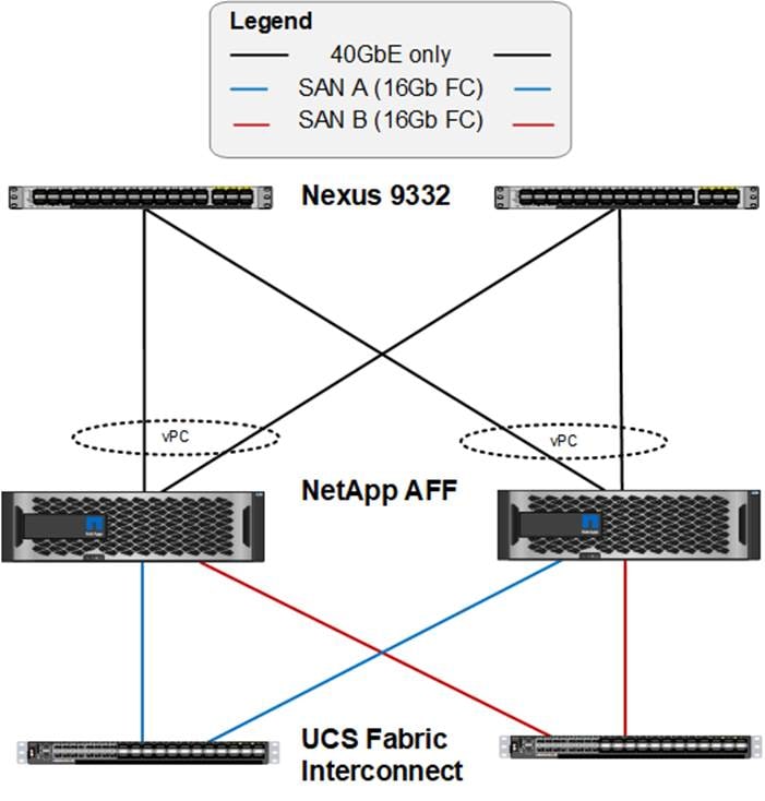
Figure 5 illustrates the initial storage configuration of this solution as a two-node high availability (HA) pair running clustered Data ONTAP in a switchless cluster configuration. Storage system scalability is easily achieved by adding storage capacity (disks and shelves) to an existing HA pair, or by adding more HA pairs to the cluster or storage domain.
![]() Note: For SAN environments, NetApp clustered Data ONTAP allows up to 6 HA pairs or 12 nodes. For NAS environments, it allows 12 HA pairs or 24 nodes to form a logical entity.
Note: For SAN environments, NetApp clustered Data ONTAP allows up to 6 HA pairs or 12 nodes. For NAS environments, it allows 12 HA pairs or 24 nodes to form a logical entity.
The HA interconnect allows each node in an HA pair to assume control of its partner's storage (disks and shelves) directly. The local physical HA storage failover capability does not extend beyond the HA pair. Furthermore, a cluster of nodes does not have to include similar hardware. Rather, individual nodes in an HA pair are configured alike, allowing customers to scale as needed, as they bring additional HA pairs into the larger cluster.
Validated System Hardware Components
The following components were used to validate this Cisco Nexus 9000 ACI design:
· Cisco Unified Computing System
· Cisco Nexus 9332 Series Leaf Switch
· Cisco Nexus 93180YC-EX Series Leaf Switch
· Cisco Nexus 9336 Spine Switch
· Cisco Application Policy Infrastructure Controller (APIC)
· NetApp All-Flash FAS Unified Storage
Logical Build
This solution uses Microsoft System Center 2016 VMM to deploy and manage the tenant Hyper-V hosts and cluster. Before tenant hosts were deployed, a two-server or two-node Hyper-V Management cluster was manually deployed to run VMM and the other management VMs. This cluster was built by installing Microsoft Windows Server 2016 with Desktop Experience on a Cisco UCS server with either iSCSI or FC SAN boot with a single SAN path since the Windows OS Installer does not support multipathing. When the OS was installed, NetApp Host Utilities and NetApp SnapDrive were installed to get SAN multipathing fully setup. When the multipathing was setup, the Sysprep utility was used to prepare the OS boot LUN for cloning with NetApp FlexClone technology. The boot LUN was cloned and clone LUNs remapped for the two management hosts. This cloning process worked for the same model server, for example Cisco UCS B200 M5. If a different server model is used, a new golden LUN needs to be built for that server model.
When the cloned servers were brought up, multipathing was restored and the Hyper-V role was installed. Then a Hyper-V virtual switch was built on the host’s first two Cisco Virtual NICs (vNICs) with a VM network for In-Band Management. A Core-Services (which will be explained later in this document) VM network could also be added to this virtual switch. At this point, the SCVMM VM was built and stored on the first host’s boot drive. Once SCVMM was built, the Cisco APIC-controlled virtual switch was added on the third and fourth vNICs with Microsoft Switch Embedded Teaming (SET). The APIC-controlled virtual switch allows port groups or VM networks to be defined in the ACI fabric and pushed into the Microsoft Virtual Switch. The following infrastructure VM networks were predefined in the ACI fabric and pushed to the Hyper-V host:
· MS-IB-MGMT: This logical network will be used for management traffic and has its own IP subnet and VLAN.
· MS-Cluster: This network will be used for Microsoft Hyper-V cluster communication and will have its own IP subnet and VLAN.
· MS-LVMN: This network will be used for Live Migration traffic and will have its own IP subnet and VLAN
· MS-SMB: This network will be used for SMB file share access/traffic and has its own IP subnet and VLAN.
When the above VM networks were available, SCVMM was used to setup the Hyper-V cluster and SAN (iSCSI or FC) Cluster Shared Volumes (CSVs). The NetApp SMI-S provider was then used to set up shared SMB volumes. Once the management Hyper-V Cluster was setup, the SCVMM VM was migrated to shared storage. It was not possible to migrate the SCVMM networking to the APIC-controlled virtual switch, and it was left on the manually built Hyper-V Virtual switch.
Tenant Hosts were built with Microsoft Windows Hyper-V server 2016, which is Windows Server Core with the Hyper-V role enabled. As will be explained later in this document, the manually built Hyper-V virtual switch was not necessary and only the APIC-controlled virtual switch was installed on the tenant hosts.
NetApp A-Series All Flash FAS
With the new A-Series All Flash FAS (AFF) controller lineup, NetApp provides industry leading performance while continuing to provide a full suite of enterprise-grade data management and data protection features. The A-Series lineup offers double the IOPS, while decreasing the latency. The A-Series lineup includes the A200, A300, A700, and A700s. These controllers and their specifications listed in Table 1 . For more information about the A-Series AFF controllers, see:
· http://www.netapp.com/us/products/storage-systems/all-flash-array/aff-a-series.aspx
· https://hwu.netapp.com/Controller/Index
Scalable and full-featured, ONTAP Data Management Software is ideal for you converged infrastructure. It allows you to consolidate all workloads onto a single system. All NetApp storage controllers are shipped with ONTAP installed and ready to begin managing your data.
Table 1 NetApp A-Series Controller Specifications
|
|
AFF A200 |
AFF A300 |
AFF A700 |
AFF A700s |
|
| NAS Scale-out |
2-8 nodes |
2-24 nodes |
2-24 nodes |
2-24 nodes |
|
| SAN Scale-out |
2-8 nodes |
2-12 nodes |
2-12 nodes |
2-12 nodes |
|
| Per HA Pair Specifications (Active-Active Dual Controller) |
|||||
| Maximum SSDs |
144 |
384 |
480 |
216 |
|
| Maximum Raw Capacity |
2.2PB |
5.9PB |
7.3PB |
3.3PB |
|
| Effective Capacity |
8.8PB |
23.8PB |
29.7PB |
13PB |
|
| Chassis Form Factor |
2U chassis with two HA controllers and 24 SSD slots |
3U chassis with two HA controllers |
8u chassis with two HA controllers |
4u chassis with two HA controllers and 24 SSD slots |
|
| ONTAP 9 Base Bundle |
ü |
ü |
ü |
ü |
|
| ONTAP 9 Premium Bundle (FlexClone, SnapMirror, SnapVault, SnapCenter, and more) |
ü |
ü |
ü |
ü |
|
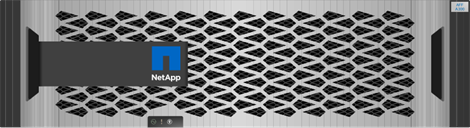
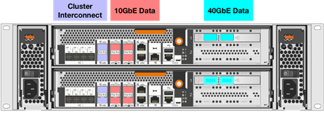
This solution utilizes the NetApp AFF A300, seen in Figure 6 and Figure 7. This controller provides the high-performance benefits of 40GbE and all flash SSDs, offering better performance than comparable options, while taking up less space in the rack. Combined with the disk shelf of 3.8TB disks, this solution can provide over ample horsepower and over 90TB of capacity, all while taking up only 5U of valuable rack space. This makes it an ideal controller for a shared workload converged infrastructure. As an infrastructure’s capacity or performance needs grow, the NetApp AFF A300 can increase capacity with additional storage shelves and performance by adding additional controllers to the cluster; a cluster can scale up to 24 nodes.
![]() Note: The 40GbE cards are installed in the expansion slot 2 and the ports are e2a, e2e.
Note: The 40GbE cards are installed in the expansion slot 2 and the ports are e2a, e2e.
Figure 6NetApp A300 Front View
Cluster Storage and HA Pairs
FlexPod Datacenter architectures usually deploy FAS or AFF controllers running ONTAP data management software. Each controller, its storage, its network connectivity, and the instance of ONTAP running on the controller is called a node.
Nodes are paired for high availability (HA). Together these pairs (up to 12 nodes for SAN, up to 24 nodes for NAS) comprise the cluster. Nodes communicate with each other over a private, dedicated cluster interconnect.
Nodes in an HA pair must use the same storage array model. However, a cluster can use any supported combination of controllers. You can scale out for capacity by adding nodes with like storage array models, or for performance by adding nodes with higher-end storage arrays.
An internal HA interconnect allows each node to continually check whether its partner is functioning and to mirror log data for the other’s nonvolatile memory. When a write request is made to a node, it is logged in NVRAM on both nodes before a response is sent back to the client or host. On failover, the surviving partner commits the failed node's uncommitted write requests to disk, ensuring data consistency.
Depending on the controller model, node storage consists of flash disks, capacity drives, or both. Network ports on the controller provide access to data. Physical storage and network connectivity resources are virtualized, visible to cluster administrators only, not to NAS clients or SAN hosts.
Connections to the other controller’s storage media allow each node to access the other's storage in the event of a takeover. Network path failover mechanisms ensure that clients and hosts continue to communicate with the surviving node.
Of course, you can scale up in all the traditional ways as well, upgrading disks or controllers as needed. ONTAP's virtualized storage infrastructure makes it easy to move data non-disruptively, meaning that you can scale vertically or horizontally without downtime.
NetApp All-Flash FAS (AFF) A-Series Design
NetApp A-Series all-flash controllers were designed from the ground up with flash storage in mind. They provide industry leading density, scalability, and network connectivity, allowing customers to do more with their flash storage. The FlexPod Datacenter with Windows Server 2016 design leverages the NetApp AFF A300 with 1.6TB SSDs. This controller provides a rich set of data management features as well as industry leading performance in a 2u form factor. ONTAP 9.1 has provides many key features that optimize SSD performance and endurance, including the following:
· Coalesced writes to free blocks to maximize flash performance and longevity
· Flash-specific read path optimizations to enable consistent low latency
· Advanced drive partitioning to increase storage efficiency, increasing usable capacity by almost 20%
· Support for multi-stream writes to increase write performance to SSDs
The FlexPod Datacenter converged infrastructure supports a variety of NetApp FAS controllers, including the AFF A-Series, AFF8000, FAS9000, FAS8000, FAS2600 and FAS2500 platforms. For a full list of supported controllers, please see the NetApp Interoperability Matrix Tool (IMT) and the FlexPod Technical Specification.
Beginning with ONTAP 9.1, the X1134A adapter is supported on AFF A300 platforms. The X1134A is a 2-port 32 Gb FC target only adapter. ONTAP 9.1 also supports adding 40G Ethernet adapters as PCI expansion cards on AFF A300 system. These 40G Ethernet adapters are part of the FlexPod Datacenter with Microsoft Windows 2016 design.
For more information about the AFF A-series product family, see http://www.netapp.com/us/products/storage-systems/all-flash-array/aff-a-series.aspx.
NetApp ONTAP 9.1
In addition to the NetApp AFF A300, this design leverages ONTAP 9.1. ONTAP data management software offers unified storage for applications that read and write data over block- or file-access protocols, in storage configurations that range from high-speed flash, to lower-priced spinning media, to cloud-based object storage.
ONTAP implementations run on NetApp-engineered Fabric-Attached Storage (FAS) or AFF appliances, on commodity hardware (ONTAP Select), and in private, public, or hybrid clouds (NetApp Private Storage, ONTAP Cloud). Specialized implementations offer best-in-class converged infrastructure (FlexPod Datacenter) and access to third-party storage arrays (FlexArray Virtualization).
Together these implementations form the basic framework of the NetApp Data Fabric, with a common software-defined approach to data management and fast, efficient replication across platforms. FlexPod and ONTAP can serve as the foundation for hybrid cloud and virtualization designs. NetApp Storage Virtual Machine (SVM)
A cluster serves data through at least one and possibly multiple storage virtual machines (SVMs; formerly called Vservers). An SVM is a logical abstraction that represents the set of physical resources of the cluster. Data volumes and network logical interfaces (LIFs) are created and assigned to an SVM and may reside on any node in the cluster to which the SVM has been given access. An SVM may own resources on multiple nodes concurrently, and those resources can be moved non-disruptively from one node to another. For example, a flexible volume can be non-disruptively moved to a new node and aggregate, or a data LIF can be transparently reassigned to a different physical network port. The SVM abstracts the cluster hardware and it is not tied to any specific physical hardware.
An SVM can support multiple data protocols concurrently. Volumes within the SVM can be joined together to form a single NAS namespace, which makes all of an SVM's data available through a single share or mount point to NFS and CIFS clients. SVMs also support block-based protocols, and LUNs can be created and exported by using iSCSI, FC, or FCoE. Any or all of these data protocols can be configured for use within a given SVM.
Because it is a secure entity, an SVM is only aware of the resources that are assigned to it and has no knowledge of other SVMs and their respective resources. Each SVM operates as a separate and distinct entity with its own security domain. Tenants can manage the resources allocated to them through a delegated SVM administration account. Each SVM can connect to unique authentication zones such as Active Directory, LDAP, or NIS. A NetApp cluster can contain multiple SVMs. If you have multiple SVMs, you can delegate an SVM to a specific application. This allows administrators of the application to access only the dedicated SVMs and associated storage, increasing manageability, and reducing risk.
SMB in ONTAP 9.1
SMB’s low cost, ease of deployment, ease of administration and rich integration with Windows server and Active Directory make it default file-sharing protocol for Microsoft Hyper-V ecosystem. Features such as scale-out, transparent failover, persistent handles and witness enable Continuously Available (CA) shares. ONTAP has supported SMB 3.0 by default since clustered Data ONTAP 8.2.1. This enables NetApp customers to use SMB 3.0 features introduced in Windows Server 2012 and allows Microsoft Hyper-V to use ONTAP volumes to host VM virtual disks and configuration settings.
Beginning with ONTAP 9, SMB 3.1.1 and enhanced features for SMB 2.0 and later are supported. The following enhancements are supported in SMB 2.0 and later:
· Workgroup authentication. You can now configure a CIFS server in a workgroup with CIFS clients that authenticate to the server by using locally defined users and groups.
· Large MTU. Increased efficiency and throughput are now enabled by packet sizes up to 1MB; previously, the maximum size was 64KB. Note: Large MTU values must be enabled through the CIFS server. Small packet sizes might result in performance degradation.
· Support for CIFS server in workgroup mode. Beginning with ONTAP 9, you can configure a CIFS server in a workgroup. This allows you to configure the CIFS server when the Microsoft Active Directory domain infrastructure is not available. A CIFS server in workgroup mode supports only NTLM authentication and does not support Kerberos authentication. Certain CIFS features are not supported by a CIFS server in workgroup mode. For more information about CIFS management, see the ONTAP 9 CIFS Reference.
· Scale-Out: ONTAP is scale-out by design. A file share can be accessed over multiple nodes to provide better utilization of network bandwidth.
· Transparent failover: In case, either partner of an HA pair experiences a failover (or upgrade event), the partner node takes over CA share. Transparent failover allows SMB 3 clients to rapidly establish connections with CA shares on partner node.
· Witness: ONTAP enables witness by correctly configuring SVM and CA with certain requirements. On a CA share, witness provides rapid and non-disruptive operations by notifying SMB 3 clients that a session has been lost and redirecting them to a different data LIF.
· Persistent handles: Persistent handles are enabled by default in ONTAP. Even though new session is established on a new node, lock state is preserved and operations are non-disruptive to the client.
· AES-128-CCM Encryption: ONTAP allows SMB encryption to be enabled at a SVM level or at the share level.
Storage Efficiency
Storage efficiency has always been a primary architectural design point of ONTAP. A wide array of features allows businesses to store more data using less space. In addition to deduplication and compression, businesses can store their data more efficiently by using features such as unified storage, multi-tenancy, and NetApp Snapshot® technology. Storage efficiency features with ONTAP 9 include:
· Thin provisioning
A thin-provisioned volume or LUN is one for which storage is not reserved in advance. Instead, storage is allocated dynamically, as it is needed. Free space is released back to the storage system when data in the volume or LUN is deleted.
· Deduplication
Deduplication reduces the amount of physical storage required for a volume (or all the volumes in an AFF aggregate) by discarding duplicate blocks and replacing them with references to a single shared block. Reads of deduplicated data typically incur no performance charge. Writes incur a negligible charge except on overloaded nodes.
· Compression
Compression reduces the amount of physical storage required for a volume by combining data blocks in compression groups, each of which is stored as a single block. Reads of compressed data are faster than in traditional compression methods because ONTAP decompresses only the compression groups that contain the requested data, not an entire file or LUN.
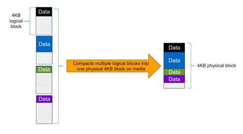
· Compaction
Compaction, which was introduced in ONTAP 9, is the latest patented storage efficiency technology released by NetApp. In the ONTAP WAFL file system, all I/O takes up 4KB of space, even if it does not actually require 4KB of data. Compaction combines multiple blocks that are not using their full 4KB of space together into one block. This one block can be more efficiently stored on-disk to save space. See Figure 8 for an illustration of compaction.
· FlexClone volumes, files, and LUNs
FlexClone technology references Snapshot metadata to create writable, point-in-time copies of a volume. Copies share data blocks with their parents, consuming no storage except what is required for metadata until changes are written to the copy. FlexClone files and FlexClone LUNs use identical technology, except that a backing Snapshot copy is not required.
NetApp Volume Encryption
Data security continues to be an important consideration for customers purchasing storage systems. NetApp has supported self-encrypting drives in storage clusters prior to ONTAP 9. However, in ONTAP 9, the encryption capabilities of ONTAP are extended by adding an Onboard Key Manager (OKM). The OKM generates and stores the keys for each of the drives in ONTAP, allowing ONTAP to provide all functionality required for encryption out of the box. Through this functionality, sensitive data stored on disks is secure and can only be accessed by ONTAP.
In ONTAP 9.1, NetApp extends the encryption capabilities further with NetApp Volume Encryption (NVE). NVE is a software-based mechanism for encrypting data. It allows a user to encrypt data at the per volume level instead of requiring encryption of all data in the cluster, thereby providing more flexibility and granularity to the ONTAP administrators. Once enabled, this encryption extends to Snapshot copies and FlexClone® volumes created in the cluster. To preserve all storage efficiency benefits, ONTAP executes NVE after all storage efficiency features. This ensures that customers have secure encrypted data while enjoying the benefits of reduced capacity utilization in the cluster.
For more information about encryption in ONTAP 9.1, see the NetApp Encryption Power Guide:
https://library.netapp.com/ecm/ecm_download_file/ECMLP2572742
NetApp FlexGroup
Beginning in ONTAP 9.1, NetApp introduced the FlexGroup - a scale-out NAS container that provides high performance, automatic load distribution, and scalability. A FlexGroup volume contains several FlexVol volumes that automatically and transparently share traffic in the cluster.
Figure 9NetApp FlexGroup
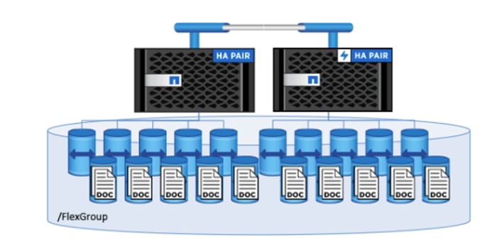
Files in a FlexGroup volume are allocated to individual member volumes and are not striped across volumes or nodes. When a client adds files and sub-directories to a FlexGroup volume, ONTAP automatically determines the best FlexVol member to use for storing each new file and subdirectory. The FlexGroup volume attempts to organize the files, both for fastest accesses and for better throughput performance.
Advantages of NetApp ONTAP FlexGroup
· Massive capacity: FlexGroup volumes can scale up to multiple petabytes and with high file counts (hundreds of billions of files), The only limiting factors being the physical limits of the hardware and total volume limits of ONTAP. For example, a 10-node cluster can have a 20PB FlexGroup volume that can handle 400 billion files
· Predictable low latency for High-metadata workload: A FlexGroup volume utilizes all the cluster resources i.e. multiple aggregates, nodes, CPU cores and other hardware assets, thereby enabling multiple volume affinities to a single storage container for metadata intensive workloads.
· Ease of management: A FlexGroup volume can provision storage across every node and aggregate in a cluster (without any junction path / capacity management overhead) through the FlexGroup tab in NetApp OnCommand® System Manager.
Backup and Replication
Traditionally, ONTAP replication technologies served the need for disaster recovery (DR) and data archiving. With the advent of cloud services, ONTAP replication has been adapted to data transfer between endpoints in the NetApp Data Fabric. The foundation for all these uses is ONTAP Snapshot technology.
· Snapshot copies
A Snapshot copy is a read-only, point-in-time image of a volume. The image consumes minimal storage space and incurs negligible performance overhead because it records only changes to the active file system since the last Snapshot copy. A volume can contain up to 255 Snapshot copies.
· SnapMirror disaster recovery and data transfer
SnapMirror is disaster recovery technology, designed for failover from primary storage to secondary storage at a geographically remote site. As its name implies, SnapMirror creates a replica, or mirror, of your working data in secondary storage from which you can continue to serve data in the event of a catastrophe at the primary site.
· SnapVault archiving
SnapVault is archiving technology, designed for disk-to-disk Snapshot copy replication for standards compliance and other governance-related purposes. In contrast to a SnapMirror relationship, in which the destination volume contains only the Snapshot copies currently in the source volume, a SnapVault destination volume typically retains point-in-time Snapshot copies created over a much longer period.
· MetroCluster continuous availability
MetroCluster configurations protect data by implementing two physically separate, mirrored clusters. Each cluster synchronously replicates the data and SVM configuration of the other. In the event of a disaster at one site, an administrator can activate the mirrored SVM and begin serving data from the surviving site.
SAN Boot
SAN boot for the Cisco UCS servers is considered a best practice in the FlexPod Datacenter solution. SAN boot takes advantage of the stateless compute capabilities of Cisco UCS, and enables the operating system to be safely secured by the NetApp All Flash FAS storage system, providing better performance and security. In this design, SAN boot was validated with iSCSI and Fibre Channel (FC). FCoE is also supported. Please see the SAN Architecture section for cabling differences between the different validations.
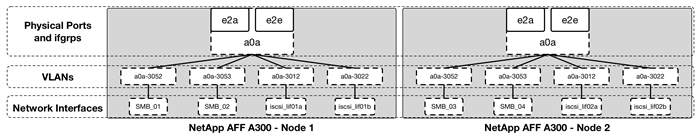
In the iSCSI validation, NetApp interface groups are used for all traffic. iSCSI traffic passes through the Cisco ACI fabric and ACI policy can be applied to iSCSI traffic. VLAN interfaces for each iSCSI VLAN are created. Logical network interfaces (LIFs) are created on each VLAN interface. Cisco UCS service profiles are created with two iSCSI vNICs - one for each iSCSI VLAN and on each switching fabric. In the iSCSI validation, 4 iSCSI network interfaces were created, providing each Windows server 2 active optimized paths and 2 active un-optimized paths to its boot LUN. This network interface and port layout can be seen in Figure 10.
In the FC validation, 4 FC network interfaces were created, providing each Windows server 2 active optimized paths and 2 active un-optimized paths to its boot LUN. The separate FC ports were directly connected to the Cisco UCS Fabric Interconnects. FC traffic does not pass through the ACI fabric and does not have ACI policy applied.
In all SAN boot configurations mentioned above, Multipath I/O (MPIO) in combination with a Device-Specific Module (DSM) is configured in Windows to establish multiple connections to the boot LUN on the NetApp controllers. MPIO software is required in any configuration which provides more than a single path to the LUN. Because there are multiple paths to the LUN, SAN network interfaces are not configured to fail over to an available port. Instead, the network interface will be disabled and the host chooses a new optimized path on a different network interface. ALUA is an industry standard protocol for identifying optimized paths between a storage system and a host. ALUA enables the Windows initiator to query the target about path attributes, such as primary and secondary paths. ALUA can be enabled on an ONTAP interface group (igroup) and is automatically enabled for all configurations described in this guide.
SMB vs SAN for Virtual Machine Disks
Microsoft Hyper-V enables shared storage of virtual machine (VM) files, including configuration, virtual hard disk (VHD) files, and snapshots, on SMB file shares or SAN LUNs via CSVs. In this design, both options were validated to ensure adequate performance and resiliency. While there are reasons you may want to use a SAN LUN for VM files and it may be required for certain applications, the preferred method in this design was the SMB 3.0 file share. The capabilities in ONTAP 9.1 support SMB 3.0 features like scale-out, transparent failover, and persistent handles and writes, enabling the file share to serve as a Continuously Available (CA) share.
Some advantages of SMB file shares for VM files are:
· Ease of provisioning and management: CA shares can be easily provisioned using Virtual Machine Manager (through NetApp SMI-S provider) with appropriate authorization and authentication rules.
· High Availability: SMB shares also enable simpler management of storage resources in a failover cluster without having to create a Clustered Shared Volume (CSV) to have simultaneous read-write access to the same LUN(disk).
· Swift VM migration: Since VM disk and configuration is stored on the same storage accessible by multiple Hyper-V hosts, only the VM information needs to be moved among Hyper-V hosts.
· Reduced expenditures: Multi-protocol support for storage access in ONTAP and rich integration with VMM result in reduced capital and operating expenses.
Cisco Nexus 9000 ACI
In this Cisco Validated Design, the Cisco Nexus 9336 Spine and the Cisco Nexus 9332 or 93180 leaf switches provide an ACI based Ethernet switching fabric for communication between the virtual machine and bare metal compute, SMB and iSCSI based storage and the existing traditional enterprise networks. Similar to previous versions of FlexPod, the virtual port channel plays an important role in providing the necessary connectivity.
Virtual Port Channel (vPC) Configuration
A virtual PortChannel (vPC) allows a device's Ethernet links that are physically connected to two different Cisco Nexus 9000 Series devices to appear as a single PortChannel. In a switching environment, a vPC provides the following benefits:
· Allows a single device to use a PortChannel across two upstream devices
· Eliminates Spanning Tree Protocol blocked ports and uses all available uplink bandwidth
· Provides a loop-free topology
· Provides fast convergence if either one of the physical links or a device fails
· Helps ensure high availability of the overall FlexPod system
Unlike an NxOS based design, a vPC configuration in ACI does not require a vPC peer-link to be explicitly connected and configured between the peer-devices (leaves). The peer communication is carried over the 40G connections through the Spines.
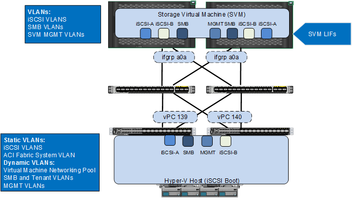
Compute and Storage Connectivity
Cisco UCS Fabric Interconnects and NetApp storage systems are connected to the Nexus 9000 leaf switches using vPCs. The Port Channels connecting NetApp controllers to the ACI fabric are configured with three types of VLANs:
· iSCSI VLANs to provide storage LUN access including boot LUNs
· SMB VLANs to access shared storage volumes to store VMs
· Management VLAN(s) to provide access to Tenant SVMs
The Port Channels connecting the Cisco UCS Fabric Interconnects to the ACI fabric are configured with up to six types of VLANs:
· iSCSI VLANs to provide Hyper-V hosts access to boot, application data, and datastore LUNs
· SMB VLANs to access virtual machine datastores to be used by the Hyper-V environment to host virtual machine services
· The In Band Management VLAN for management access to the Hyper-V hosts and management VMs.
· A pool of VLANs associated with an ACI Virtual Machine Manager (VMM) domain for the Microsoft Virtual Switch. VLANs from this pool are dynamically allocated by the APIC to newly created end point groups (EPGs) that become port-profiles in the APIC-Controlled Virtual Switch
· The ACI system VLAN to connect the Hyper-V Host VXLAN tunnel endpoints (VTEPs) to the ACI fabric VTEPs to allow communication between the APIC and Hyper-V Host.
· The UCS port channels also include the Live Migration and Cluster VLANs, but since those VLANs are not mapped to storage, they are not shown in the next subsections.
These VLAN configurations are covered in detail in the next subsections.
Figure 11 Compute and Storage Connectivity to Cisco Nexus 9000 ACI
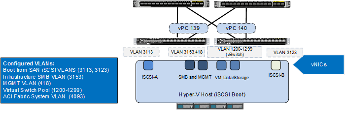
VLAN Configuration for Cisco Unified Computing System
For the Cisco Unified Computing System to Cisco Nexus 9000 connectivity, iSCSI VLANs associated with boot from SAN configuration and the SMB VLANs used by the infrastructure Hyper-V hosts are pre-configured on the Cisco UCS Fabric Interconnect along with the Windows Cluster VLANs. Note that the SMB and Windows Clustering VLAN interfaces will also be configured in the APIC-controlled virtual switch and it is only necessary to configure the IB-MGMT and iSCSI VLANs in UCS, but it does not hurt to manually configure these VLANs in UCS. In Figure 12, VLANs 3113 and 3123 are the Infrastructure Tenant iSCSI-A and iSCSI-B VLANs that are assigned to individual virtual NICs (vNICs) and enabled on the uplink ports. The Infrastructure SMB (3153) and In Band Management (418) VLANs are assigned to a pair of vNICs also enabled on the uplink ports. Note that any tenant-based iSCSI VLANs would be assigned to the APIC-controlled virtual switch.
In an ACI based configuration, when the APIC-controlled virtual switch is being used, the Cisco APIC connects to SCVMM and the Hyper-V hosts via agent and automatically configures VM networks or port groups on the virtual switch based on the user-defined End Point Group (EPG) configuration. These VM networks are associated with a dynamically assigned VLAN from a pre-defined pool in Cisco APIC. Since Cisco APIC does not configure the Cisco UCS Fabric Interconnect, this range of pool VLANs has to be pre-configured on the uplink vNIC interfaces of the Hyper-V service profiles. In Figure 12, VLAN 1200-1299 is part of the APIC defined VLAN pool.
Figure 12 VLAN Configuration for Cisco UCS Connectivity
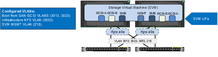
VLAN Configuration for NetApp
When configuring NetApp controllers for Cisco Nexus 9000 connectivity, iSCSI VLANs used for boot from SAN and application data LUN access, SMB VLANs for the Hyper-V host datastore access and SVM management LIFs are defined on the NetApp controllers. In Figure 13, VLANs 3053, 3013 and 3023 are the SMB, iSCSI-A and iSCSI-B VLANs for the infrastructure tenant. VLAN 218 is the SVM management interface.
![]() Note: Currently in ACI, a VLAN can only be associated with a single physical domain when the L2 VLAN Scope is Global instead of Port Local, therefore the SMB and iSCSI VLAN IDs used on Cisco Unified Computing System and NetApp controllers are different. Also, when multiple domains (physical or L2) connect to a bridge domain, each domain must use a unique VLAN. In Figure 12 and Figure 13, VLANs 3153, 3113, 3123, and 418 are defined on Cisco Unified Computing System whereas VLANs 3053, 3013, 3023 and 218 are defined on NetApp controllers for the same storage path. The ACI fabric provides the necessary VLAN translation to enable communication between the host interface and the LIF EPGs. For additional information about EPGs and VLAN mapping, refer to the Application Centric Infrastructure (ACI) Design section.
Note: Currently in ACI, a VLAN can only be associated with a single physical domain when the L2 VLAN Scope is Global instead of Port Local, therefore the SMB and iSCSI VLAN IDs used on Cisco Unified Computing System and NetApp controllers are different. Also, when multiple domains (physical or L2) connect to a bridge domain, each domain must use a unique VLAN. In Figure 12 and Figure 13, VLANs 3153, 3113, 3123, and 418 are defined on Cisco Unified Computing System whereas VLANs 3053, 3013, 3023 and 218 are defined on NetApp controllers for the same storage path. The ACI fabric provides the necessary VLAN translation to enable communication between the host interface and the LIF EPGs. For additional information about EPGs and VLAN mapping, refer to the Application Centric Infrastructure (ACI) Design section.
Figure 13 VLAN Configuration for NetApp Connectivity
Application Centric Infrastructure (ACI) Design
The Cisco ACI fabric consists of discrete components that operate as routers and switches but are provisioned and monitored as a single entity. These components and the integrated management allow ACI to provide advanced traffic optimization, security, and telemetry functions for both virtual and physical workloads. The Cisco ACI fabric is deployed in a leaf-spine architecture. The network provisioning in an ACI-based FlexPod is quite different from traditional FlexPod and requires a basic knowledge of some of the core concepts of ACI.
ACI Components
Leaf switches: The ACI leaf provides physical server and storage connectivity as well as enforces ACI policies. A leaf typically is a fixed form factor switch such as the Cisco Nexus N9K-C9332PQ, the N9K-C93180YC-EX, and N9K-C9372PX switches. Leaf switches also provide a connection point to the existing enterprise or service provider infrastructure. The leaf switches provide both 10G and 40G Ethernet ports for connectivity.
In the FlexPod with ACI design, Cisco UCS Fabric Interconnect, NetApp Controllers and WAN/Enterprise routers are connected to a pair of leaves for high availability.
Spine switches: The ACI spine provides the mapping database function and connectivity among leaf switches. A spine can be the Cisco Nexus® N9K-C9508 switch equipped with N9K-X9736PQ line cards or fixed form-factor switches such as the Cisco Nexus N9K-C9336PQ ACI spine switch. Spine switches provide high-density 40 Gigabit Ethernet connectivity between leaf switches.
Tenant: A tenant (Figure 14) is a logical container or a folder for application policies. This container can represent an actual tenant, an organization, an application or can just be used for the convenience of organizing information. A tenant represents a unit of isolation from a policy perspective. All application configurations in Cisco ACI are part of a tenant. Within a tenant, you define one or more Layer 3 networks (VRF instances), one or more bridge domains per network, and EPGs to divide the bridge domains.
FlexPod with ACI design requires creation of a tenant called “FP-Foundation" for providing compute to storage connectivity to setup the boot from SAN environment as well as for accessing the Infrastructure datastores using SMB. The design also utilizes the predefined “common" tenant to host core services (such as DNS, AD etc.) required by all the tenants. In most cases, each subsequent application deployment will require creation of a dedicated tenant.
Application Profile: Modern applications contain multiple components. For example, an e-commerce application could require a web server, a database server, data located in a storage area network, and access to outside resources that enable financial transactions. An application profile (Figure 14) models application requirements and contains as many (or as few) End Point Groups (EPGs) as necessary that are logically related to providing the capabilities of an application. Depending on the tenant requirements, in the FlexPod with ACI design, an application profile will be used to define a multi-tier application (such as Microsoft SharePoint) as well as to define storage connectivity using different storage protocols (SMB and iSCSI).
Bridge Domain: A bridge domain represents a L2 forwarding construct within the fabric. One or more EPGs can be associated with one bridge domain or subnet. A bridge domain can have one or more subnets associated with it. One or more bridge domains together form a tenant network.
For FlexPod design, setting up a bridge domain is an important consideration. A bridge domain in ACI is equivalent to a broadcast layer-2 domain in traditional Ethernet networks. When a bridge domain contains endpoints belonging to different VLANs (outside of the ACI fabric), a unique MAC address is required for every unique endpoint. NetApp storage controllers, however, use the same MAC address for an interface group and all the VLAN interface ports defined for that interface group on that storage node. As a result, all the LIFs on a NetApp interface group end up sharing a single MAC address even though these LIFs belong to different VLANs.
a02-affa300::> network port show -fields mac
node port mac
------------- ---- -----------------
a02-affa300-1 a0a 02:a0:98:aa:b3:9f
a02-affa300-1 a0a-218
02:a0:98:aa:b3:9f (SVM-MGMT)
a02-affa300-1 a0a-3013
02:a0:98:aa:b3:9f (iSCSI-A)
a02-affa300-1 a0a-3023
02:a0:98:aa:b3:9f (iSCSI-B)
a02-affa300-1 a0a-3053
02:a0:98:aa:b3:9f (SMB)
To overcome potential issues caused by overlapping MAC addresses, multiple bridge domains need to be deployed for correct storage connectivity. The details of the required bridge domains are covered in the design section below.
End Point Group (EPG): An End Point Group (EPG) is a collection of physical and/or virtual end points that require common services and policies. An End Point Group example is a set of servers or storage LIFs on a common VLAN providing a common application function or service. While the scope of an EPG definition is much wider, in the simplest terms an EPG can be defined on a per VLAN segment basis where all the servers or VMs on a common LAN segment become part of the same EPG.
In the FlexPod design, various application tiers, host interface ports for iSCSI, SMB and Live Migration connectivity, and NetApp LIFs for SVM-Management and SMB and iSCSI datastores are placed in separate EPGs. The design details are covered in the following sections.
Contracts: A service contract can exist between two or more participating peer entities, such as two applications running and talking to each other behind different endpoint groups, or between providers and consumers, such as a DNS contract between a provider entity and a consumer entity. Contracts utilize filters to limit the traffic between the applications to certain ports and protocols.
Figure 14 ilustrates the relationship between the ACI elements defined above. As shown in the figure, a Tenant can contain one or more application profiles and an application profile can contain one or more end point groups. The devices in the same EPG can talk to each other without any special configuration. Devices in different EPGs can talk to each other using contracts and associated filters. A tenant can also contain one or more bridge domains and multiple application profiles and different end point groups can utilize the same bridge domain. When different end point groups share the same bridge domain, communication between those end point groups can occur at Layer 2.
Figure 14 ACI—Relationship between Major Components
End Point Group (EPG) Mapping in a FlexPod Environment
In the FlexPod with ACI infrastructure, traffic is associated with an EPG in one of the two following ways:
· Statically mapping a VLAN to an EPG (Figure 15)
· Associating an EPG with a Virtual Machine Manager (VMM) domain for the APIC-controlled virtual switch and allocating a VLAN dynamically from a pre-defined pool in APIC (Figure 16)
Figure 15 EPG—Static Port Binding
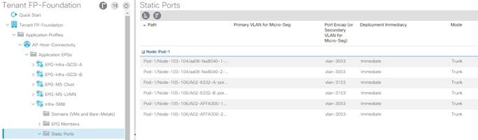
Figure 16 EPG—Virtual Machine Manager Domain Binding
The first method of statically mapping a VLAN is useful for the following:
· Mapping storage VLANs on the NetApp Controllers to storage protocol-related EPGs. These storage EPGs become the storage "providers" and are accessed by the Hyper-V host either by being in the same EPG or separate EPGs through consumed contracts.
· Connecting an ACI environment to an existing layer-2 bridge domain, such as an existing management segment. A VLAN on an out of band management switch is statically mapped to a management EPG in the common tenant to provide management services to VMs across all the tenants.
· Mapping iSCSI and SMB datastore VLANs on Cisco UCS to EPGs that consume the NetApp storage EPGs. Figure 15 illustrates this mapping.
· Mapping the Live Migration or Cluster VLAN on Cisco UCS to an EPG.
· Mapping tenant iSCSI for tenant VMs or Hyper-V servers to access iSCSI LUNs on storage.
The second method of dynamically mapping a VLAN to an EPG by defining a VMM domain is used for the following:
· Deploying VMs in a multi-tier Application as shown in Figure 21.
· Deploying SMB related storage access for the application Tenant as shown in Figure 21.
Virtual Machine Networking
The Cisco APIC automates the networking for all virtual and physical workloads including access policies and L4-L7 services. When connected to SCVMM and the Hyper-V hosts, APIC controls the configuration of the VM switching as detailed in the following sections.
Virtual Machine Manager (VMM) Domains
For a SCVMM, the creation and network configuration of the Microsoft Virtual Switch and the set-up of port groups or VM networks are performed by the APIC. The APIC communicates with SCVMM to publish network policies that are applied to the virtual workloads. To position an application, the application administrator deploys the VMs and places the VM NIC(s) into the appropriate VM networks for various application tiers. A VMM domain contains multiple EPGs and hence multiple port groups.
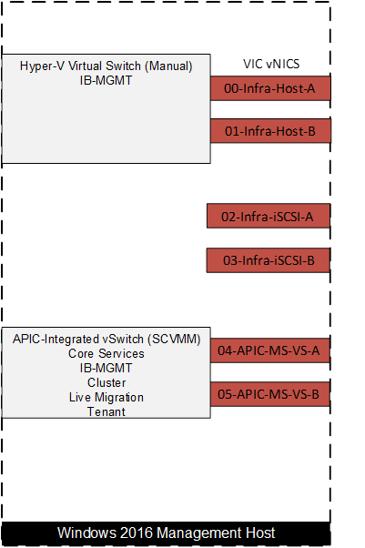
Hyper-V Host Port Layout and APIC-Controlled Virtual Switch
While a tenant application deployment utilizes port groups on an APIC-controlled virtual switch, some of the core functionality such as in-band management access, and iSCSI access utilizes either the manually built Hyper-V virtual switch or individual network interfaces. The resulting distribution of network ports and VM networks on Hyper-V management host is shown in Figure 17. In the Cisco UCS service profile for Hyper-V management hosts, iSCSI and management VLANs are defined on the vNIC interfaces used by the Hyper-V virtual switch and iSCSI interfaces. SCVMM resides in the IB-MGMT VLAN on the Hyper-V virtual switch. All future-provisioned VLAN interfaces should be added as EPGs to the APIC-controlled virtual switch. Both the host management network interface and the SCVMM network interface are placed in the FP-Foundation IB-MGMT EPG on the Hyper-V Virtual switch. The Core-Services EPG can also optionally be associated with this virtual switch and these interfaces placed in this EPG.
Figure 17 Hyper-V Management Host Network Design
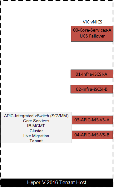
The Hyper-V tenant host design (Figure 18) is a simplified version of the management host design. Since SCVMM already exists in the environment, a VM network does not have to be manually built for placement of SCVMM. The manually-built Hyper-V virtual switch with two vNIC uplinks becomes a single vNIC interface in the Core Services EPG with UCS failover to protect it. This interface is placed in Core Services to allow communication with the tenant NetApp SVM interface. The iSCSI interfaces and APIC-controlled virtual switch are the same. This design allows the same tenant host design to be used for multiple tenants. Tenant hosts can either be dedicated to individual tenants or shared among multiple tenants. If tenant hosts are dedicated to individual tenants, VRFs in the ACI fabric and IPspaces in the NetApp storage controllers can be used to provide overlapping IP address spaces between tenants. Note also that multiple APIC-controlled virtual switches can be defined, but an individual tenant host can only have one APIC-controlled virtual switch.
Figure 18 Hyper-V Tenant Host Network Design
Onboarding Infrastructure Services
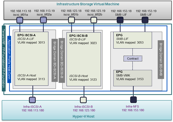
In an ACI fabric, all the applications, services and connectivity between various elements are defined within the confines of tenants, application profiles, bridge domains and EPGs. The ACI constructs for core infrastructure services including an overview of the connectivity and relationship between various ACI elements is covered in Figure 19.
Figure 19 Design Details of the FP-Foundation (Infrastructure) Tenant
ACI Design for Foundation Tenant
· Tenant Role: To enable the compute to storage connectivity for accessing iSCSI boot LUNs and SMB datastores. The boot LUNs enable stateless compute functionality while the SMB datastores host all the Infrastructure VMs.
· VRF: Each tenant in this implementation was assigned a separate Virtual Routing and Forwarding (VRF) instance, providing each tenant a separate routing table. Additionally, with application tenants, each tenant was assigned a separate Storage Virtual Machine (SVM) with its own IPspace in the NetApp Storage, allowing tenants the capability of using overlapping IP address spaces. The FP-Foundation Tenant’s storage SVM was assigned to the Default IPspace in the NetApp Storage.
· Application Profile, EPGs and Contracts: The foundation tenant comprises of two application profiles, Host-Connectivity, and IB-MGMT.
![]() Note: IB-MGMT and Windows Cluster VLANs are not shown in the diagrams for this section.
Note: IB-MGMT and Windows Cluster VLANs are not shown in the diagrams for this section.
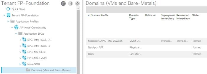
· Application Profile Host-Conn comprises of four EPGs, "Infra-iSCSI-A”, "Infra-iSCSI-B”, “Infra-SMB-LIF”, and “Infra-SMB-Host” as shown in Figure 19.
- The first EPG and static path mapping maps the VLAN associated with the SMB LIF interfaces on the NetApp Infrastructure SVM (VLAN 3053). This mapping provides SMB storage access to the compute environment.
- The second EPG and static path mapping maps the VLAN associated with the SMB host port for the management Hyper-V host (VLAN 3153).
- An SMB contract connects these two EPGs, and can include a filter to only allow SMB traffic to pass.
Figure 20 Foundation Tenant—Application Profile SMB
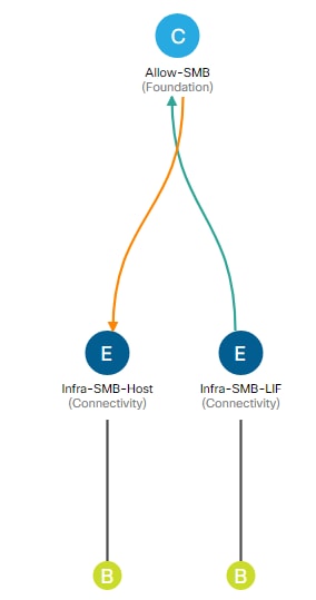
![]() Note: Each entry point into the ACI environment is mapped to a unique VLAN, because Global L2 VLANs are being used. Even though the interface ports on the Hyper-V hosts and the SMB LIF interfaces on the NetApp SVM are part of the same layer-2 domain, two different VLANs (3053 and 3153) are configured for this EPG. Also, note that flexibility exists to map the two entry points into one EPG, or to map the two entry points into two EPGs and use a restrictive contract to connect them.
Note: Each entry point into the ACI environment is mapped to a unique VLAN, because Global L2 VLANs are being used. Even though the interface ports on the Hyper-V hosts and the SMB LIF interfaces on the NetApp SVM are part of the same layer-2 domain, two different VLANs (3053 and 3153) are configured for this EPG. Also, note that flexibility exists to map the two entry points into one EPG, or to map the two entry points into two EPGs and use a restrictive contract to connect them.
- Static path mappings in the iSCSI-A EPG statically map the VLANs associated with iSCSI-A (VLAN 3013 and 3113) to the LIF interface on the NetApp Infrastructure SVM and the host interface in the Cisco UCS.
- Static path mappings in the iSCSI-B EPG statically map the VLANs associated with iSCSI-B (VLAN 3023 and 3123) to the LIF interface on the NetApp Infrastructure SVM and the host interface in the Cisco UCS.
Since the two static mapped endpoints for the two iSCSI networks are in the same EPGs, access between the iSCSI LIFs and corresponding host port is unrestricted.
· Bridge Domains: While all the EPGs in a tenant can theoretically share the same bridge domain (BD), overlapping MAC address usage by NetApp storage controllers on the interface groups across multiple VLANs determines the actual number of bridge domains required. As shown in Figure 19, the "FP-Foundation" tenant connects to two iSCSI LIFs and one SMB LIF to provide storage connectivity to the infrastructure SVM. Since these three LIFs on each storage controller share the same MAC address, a separate BD is required for each LIF. The "FP-Foundation" tenant therefore comprises of four bridge domains: BD-iSCSI-A, BD-iSCSI-B, BD-SMB, and BD-Internal.
- BD-iSCSI-A is the bridge domain configured to host EPGs for iSCSI-A traffic
- BD-iSCSI-B is the bridge domain configured to host EPGs for iSCSI-B traffic
- BD-SMB is the bridge domain configured to host EPGs for SMB traffic
- BD-Internal is the bridge domain configured to host EPGs for all other Tenant FP-Foundation traffic. This bridge domain is also utilized for hosting EPGs related to Windows Cluster and application traffic since there is no MAC address overlap with these functions.
Onboarding a 3-Tier Application
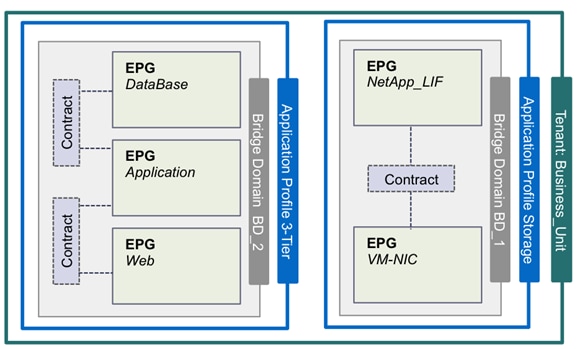
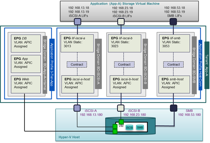
The ACI constructs for a 3-tier application deployment are a little more involved than the infrastructure tenant "FP-Foundation" covered in the last section. In addition to providing Hyper-V host to storage connectivity, various tiers of the application also need to communicate amongst themselves as well as with the storage and common or core services (DNS, AD etc.). Figure 21 provides an overview of the connectivity and relationship between various ACI elements for a sample 3-tier Application.
Some of the key highlights of the sample 3-Tier Application deployment are as follows:
· Three application profiles, Host-Conn, SVM-MGMT and 3-Tier-App are utilized to deploy the application. SVM-MGMT is not shown in Figure 21.
· Tenant Hyper-V servers will map one or more SMB datastores from a dedicated Application SVM on NetApp controllers. This datastore hosts all the application VMs.
· The host VM network for mounting SMB datastores is managed and deployed by APIC on the APIC-controlled virtual switch.
· The host VM network for mounting iSCSI datastores and VM iSCSI interfaces are managed and deployed by APIC on the APIC-controlled virtual switch.
· The SVM-MGMT EPG can be tied by contract to any of the three application tiers where access to the SVM for storage provisioning and backup is necessary.
· Four unique bridge domains are needed to host iSCSI, SMB and VM traffic.
Figure 21 Design Details of the 3-Tier Application
ACI Design for 3-Tier Application Tenant
· Tenant Role: To host a multi-tier application (App-A in this design) and to provide application specific compute to storage connectivity, a tenant named "App-A" is configured.
· VRF: Each tenant in this implementation was assigned a separate Virtual Routing and Forwarding (VRF) instance, providing each tenant a separate routing table. Additionally, with application tenants, each tenant was assigned a separate Storage Virtual Machine (SVM) with its own IPspace in the NetApp Storage, allowing tenants the capability of using overlapping IP address spaces. Two tenants were set up in the lab with separate VRFs and IPspaces. Although different VLANs were used for each tenant, the same IP subnets were used for all storage connections, i.e. 192.168.13.0/24 for iSCSI-A in both tenants. A separate Hyper-V tenant host cluster had to be used for each tenant and each datastore had a unique name.
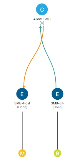
· Application Profile and EPGs: The "App-A" tenant comprises of four application profiles, "3-Tier-App", "Host-Conn", and “SVM-MGMT”.
· Application Profile "Host-Conn" comprises of six EPGs, "lif-SMB", "SMB-Host”, "lif-iSCSI-A", "iSCSI-A-Host”, "lif-iSCSI-B", "iSCSI-B-Host” as shown in Figure 21.
- EPG "lif-smb" statically maps the VLAN associated with SMB LIF on the App-A SVM (VLAN 3053). This EPG "provides" SMB storage access to the tenant environment.
- EPG "smb-host" is attached to the VMM domain to provide an SMB VM network in the Hyper-V environment. This port-group is utilized by the tenant (App-A) Hyper-V servers.
- A contract "Allow-SMB" is defined to allow SMB traffic. This contract is "Provided" by EPG lif-smb and is "Consumed" by EPG smb-host.
- Similar constructs are setup to provide iSCSI connectivity. Note that this connectivity can also be provided in a single EPG.
Figure 22 App-A—Application Profile SMB
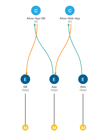
· Application Profile "3-Tier-App" comprises of three EPGs, "Web", "App", and "DB".
- EPG "Web" is attached to the VMM domain and provides a VM network to connect the web servers.
- EPG "App" is attached to the VMM domain and provides a VM network to connect the application servers.
- EPG "DB" is attached to the VMM domain and provides a VM network to connect the database servers.
- Appropriate contracts are defined to allow traffic between various application tiers.
Figure 23 App-A—3-Tier-App Application Profile
· Bridge Domain: The "App-A" tenant comprises of four bridge domains, BD-iSCSI-A, BD-iSCSI-B, BD-SMB, and BD-Internal. As explained before, overlapping MAC addresses on NetApp Controllers require iSCSI-A, iSCSI-B, SMB and SVM-MGMT traffic to use separate bridge domains.
- BD-iSCSI-A is the bridge domain configured to host EPGs configured for iSCSI-A traffic
- BD-iSCSI-B is the bridge domain configured to host EPGs configured for iSCSI-B traffic
- BD-SMB is the bridge domain configured to host EPGs configured for SMB traffic
- BD-Internal is the bridge domain configured for hosting EPGs related to SVM-MGMT and application traffic since there is no MAC address overlap with the application VMs
Core Services and Storage Management
Accessing Core Services
To provide application servers access to common services such as Active Directory (AD), Domain Name Services (DNS), management and monitoring software etc., inter-tenant contracts are utilized. The Cisco ACI fabric provides a predefined tenant named "common" to host the shared services. The policies defined in the "common" tenant are usable by all the other tenants. In addition to the locally defined contracts, all the tenants in the ACI fabric have access to the contracts defined in the "common" tenant.
In the FlexPod environment, access to core services is provided as shown in Figure 24. To provide this access:
· A common services segment is defined where core services VMs connect. The core services EPG is associated with the APIC-controlled virtual switch VMM domain. A separate services segment ensures that the access from the tenant VMs is limited to only core services' VMs.
· A static port mapping is used to link a separate, isolated In-Band management network to Core-Services.
· The EPG for the core services segment "Core-Services" is defined in the "common" tenant.
· The tenant VMs access the core services segment by consuming contracts from the "common" tenant.
· The contract filters can be configured to only allow specific services related ports.
· The tenant VMs access the core services segment using their EPG subnet gateway.
· Since the tenant VMs reside in separate subnets than the Core-Services VMs, routes must be configured in the Core-Services VMs and hosts to reach the Application tenant VMs. For this lab implementation a supernet route with destination 172.18.0.0/16 was put into each Core-Services VM. Routes needed to be shared across VRFs since the two EPGs were in different tenants.
· Unique IP subnets have to be used for each EPG connecting to Core-Services.
Figure 24 shows both "provider" EPG "Core-Services" in the tenant "common" and the consumer EPGs "Web", "App" and "DB" in tenant "App-A".
Figure 24 Core Services and Storage Management
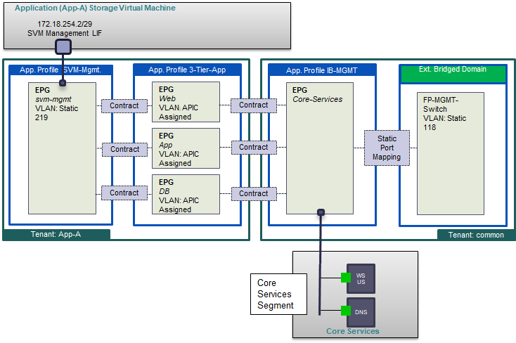
Accessing SVM Management
Some applications such as NetApp Snap Drive require direct connectivity from the application (SharePoint, Exchange, SQL, etc.) VMs to the management LIF on the tenant SVM. To provide this connectivity securely, a separate VLAN is dedicated for each tenant to define the management LIF. This VLAN is then statically mapped to an EPG in the application tenant as shown in Figure 24. Application VMs can access this LIF by defining and utilizing contracts. The SVM management LIF can also be connected to Core-Services to allow tenant Hyper-V hosts to use Snapdrive to configure tenant CSVs.
![]() Note: When an application tenant contains mappings for NetApp LIFs for storage access (iSCSI, NFS etc.), a separate bridge domain is required for the SVM management LIF because of the overlapping MAC addresses. Ensure that only one type of storage VLAN interface is connected to a given bridge domain.
Note: When an application tenant contains mappings for NetApp LIFs for storage access (iSCSI, NFS etc.), a separate bridge domain is required for the SVM management LIF because of the overlapping MAC addresses. Ensure that only one type of storage VLAN interface is connected to a given bridge domain.
NetApp SnapManager and SnapDrive with Cisco ACI
NetApp SnapDrive and the SnapManager portfolio of products greatly simplify storage provisioning and the backup of application data. In this design, the SVM management LIF is placed on a VLAN within the application tenant and a contract is built linking the application VM's management interface with the SVM management LIF. This interaction takes place through HTTPS on TCP port 443 by default.
The interaction of SnapDrive and the SVM management LIF also handle LUN provisioning, including provisioning CSVs in a Windows Cluster.
These ACI capabilities are combined with the Role-Based Access Control (RBAC) capabilities of NetApp clustered Data ONTAP to allow multiple-tenant administrators and individual-application administrators to simultaneously and securely provision and back up application data storage while taking advantage of the NetApp storage efficiency capabilities.
FlexPod Connectivity to Existing Infrastructure (Shared Layer 3 Out)
In order to connect the ACI fabric to existing infrastructure, the leaf nodes are connected to a pair of core infrastructure routers/switches. In this design, a Cisco Nexus 7000 was configured as the core router. Figure 25 shows the connectivity details from the Shared_L3_Out External Routed Domain in the “common” tenant and the “common/default” VRF. Figure 26 shows how tenants with other VRFs are connected to the Shared_L3_Out via contracts. Tenant network routes can be shared with the Nexus 7000s using OSPF and external routes from the Nexus 7000s can be shared with the tenant VRFs. Routes can also be shared across VRFs.
Figure 25 ACI Connectivity to Existing Infrastructure
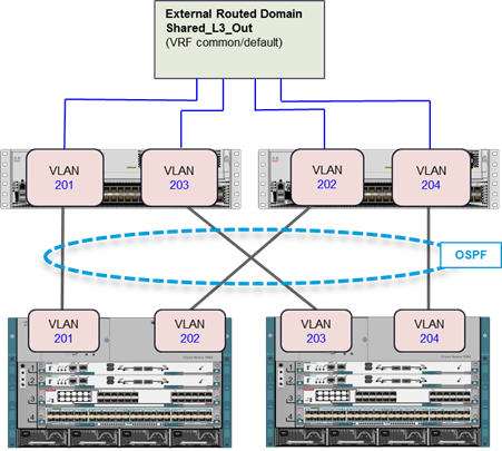
Figure 26 Connecting Tenant Networks to Shared Layer 3 Out
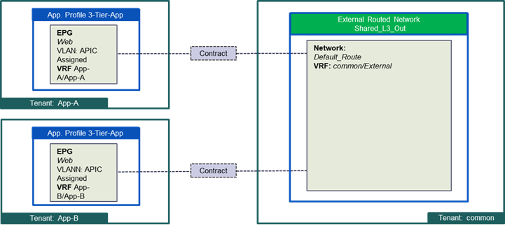
Some of the design principles for external connectivity are as follows:
· Each Leaf switch is connected to both Cisco Nexus 7000 switches for redundancy.
· A unique VRF is defined for every tenant. App-A/App-A and App-B/App-B are two such VRFs shown in Figure 26.
· Unique VLANs are configured to provide multi-path connectivity between the ACI fabric and the core infrastructure. VLANs 201-204 are configured as shown.
· On the ACI fabric, OSPF is configured to share routes. The ACI fabric learns a default route from the core router and each tenant advertises one or more "public" routable subnets to the core infrastructure across VRFs.
Cisco Unified Computing System
Cisco UCS 6300 Fabric Interconnects
The Cisco UCS Fabric interconnects provide a single point for connectivity and management for the entire system. Typically deployed as an active-active pair, the system’s fabric interconnects integrate all components into a single, highly-available management domain controlled by Cisco UCS Manager. The fabric interconnects manage all I/O efficiently and securely at a single point, resulting in deterministic I/O latency regardless of a server or virtual machine’s topological location in the system.
The Fabric Interconnect provides both network connectivity and management capabilities for Cisco UCS. IOM modules in the blade chassis support power supply, along with fan and blade management. They also support port channeling and, thus, better use of bandwidth. The IOMs support virtualization-aware networking in conjunction with the Fabric Interconnects and Cisco Virtual Interface Cards (VIC).
FI 6300 Series and IOM 2304 provide a few key advantages over the existing products. FI 6300 Series and IOM 2304 support 40GbE / FCoE port connectivity that enables an end-to-end 40GbE solution. Unified ports support 4/8/16G FC ports for higher density connectivity to SAN ports.
Table 2 The key differences between FI 6200 series and FI 6300 series
| FI 6200 Series |
FI 6300 Series |
|||
| Features |
6248 |
6296 |
6332 |
6332-16UP |
| Max 10G ports |
48 |
96 |
96* + 2** |
72* + 16 |
| Max 40G ports |
- |
- |
32 |
24 |
| Max unified ports |
48 |
96 |
- |
16 |
| Max FC ports |
48 x 2/4/8G FC |
96 x 2/4/8G FC |
- |
16 x 4/8/16G FC |
* Using 40G to 4x10G breakout cables
** Requires QSA module
Cisco UCS Differentiators
Cisco Unified Computing System is revolutionizing the way servers are managed in the datacenter. The following are the unique differentiators of Cisco Unified Computing System and Cisco UCS Manager:
· Embedded Management — In Cisco UCS, the servers are managed by the embedded firmware in the Fabric Interconnects, eliminating need for any external physical or virtual devices to manage the servers.
· Unified Fabric — In Cisco UCS, from blade server chassis or rack servers to FI, there is a single Ethernet cable used for LAN, SAN and management traffic. This converged I/O results in reduced cables, SFPs and adapters – reducing capital and operational expenses of overall solution.
· Auto Discovery — By simply inserting the blade server in the chassis or connecting rack server to the fabric interconnect, discovery and inventory of compute resource occurs automatically without any management intervention. The combination of unified fabric and auto-discovery enables the wire-once architecture of Cisco UCS, where compute capability of Cisco UCS can be extended easily while keeping the existing external connectivity to LAN, SAN and management networks.
· Policy Based Resource Classification — When a compute resource is discovered by Cisco UCS Manager, it can be automatically classified to a given resource pool based on policies defined. This capability is useful in multi-tenant cloud computing. This CVD showcases the policy based resource classification of Cisco UCS Manager.
· Combined Rack and Blade Server Management — Cisco UCS Manager can manage Cisco UCS B-series blade servers and Cisco UCS C-series rack-mount servers under the same Cisco UCS domain. This feature, along with stateless computing makes compute resources truly hardware form factor agnostic.
· Model based Management Architecture — Cisco UCS Manager architecture and management database is model based and data driven. An open XML API is provided to operate on the management model. This enables easy and scalable integration of Cisco UCS Manager with other management systems.
· Policies, Pools, Templates — The management approach in Cisco UCS Manager is based on defining policies, pools and templates, instead of cluttered configuration, which enables a simple, loosely coupled, data driven approach in managing compute, network and storage resources.
· Loose Referential Integrity — In Cisco UCS Manager, a service profile, port profile or policies can refer to other policies or logical resources with loose referential integrity. A referred policy cannot exist at the time of authoring the referring policy or a referred policy can be deleted even though other policies are referring to it. This provides different subject matter experts to work independently from each-other. This provides great flexibility where different experts from different domains, such as network, storage, security, server and virtualization work together to accomplish a complex task.
· Policy Resolution — In Cisco UCS Manager, a tree structure of organizational unit hierarchy can be created that mimics the real life tenants and/or organization relationships. Various policies, pools and templates can be defined at different levels of organization hierarchy. A policy referring to another policy by name is resolved in the organization hierarchy with closest policy match. If no policy with specific name is found in the hierarchy of the root organization, then special policy named “default” is searched. This policy resolution practice enables automation friendly management APIs and provides great flexibility to owners of different organizations.
· Service Profiles and Stateless Computing — A service profile is a logical representation of a server, carrying its various identities and policies. This logical server can be assigned to any physical compute resource as far as it meets the resource requirements. Stateless computing enables procurement of a server within minutes, which used to take days in legacy server management systems.
· Built-in Multi-Tenancy Support — The combination of policies, pools and templates, loose referential integrity, policy resolution in organization hierarchy and a service profiles based approach to compute resources makes Cisco UCS Manager inherently friendly to multi-tenant environment typically observed in private and public clouds.
· Extended Memory — The enterprise-class Cisco UCS B200 M4 blade server extends the capabilities of Cisco’s Unified Computing System portfolio in a half-width blade form factor. The Cisco UCS B200 M4 harnesses the power of the latest Intel® Xeon® E5-2600 v4 Series processor family CPUs with up to 1536 GB of RAM (using 64 GB DIMMs) – allowing huge VM to physical server ratio required in many deployments, or allowing large memory operations required by certain architectures like big data.
· Virtualization Aware Network — Cisco VM-FEX technology makes the access network layer aware about host virtualization. This prevents domain pollution of compute and network domains with virtualization when virtual network is managed by port-profiles defined by the network administrators’ team. VM-FEX also off-loads hypervisor CPU by performing switching in the hardware, thus allowing hypervisor CPU to do more virtualization related tasks. VM-FEX technology is well integrated with VMware vCenter, Linux KVM and Hyper-V SR-IOV to simplify cloud management.
· Simplified QoS — Even though Fibre Channel and Ethernet are converged in Cisco UCS fabric, built-in support for QoS and lossless Ethernet makes it seamless. Network Quality of Service (QoS) is simplified in Cisco UCS Manager by representing all system classes in one GUI panel.
Cisco UCS Design Options within this FlexPod
Cisco UCS vNICs
The FC and FCoE FlexPod architectures use just three or four Cisco UCS vNICs. The last two vNICs provisioned to the servers are teamed in the OS for failover and load balancing using the new “Switch Embedded Teaming” feature introduced in Windows Server 2016 Hyper-V for the APIC-controlled virtual switch.
In addition to the two vNICs described above, the iSCSI FlexPod architecture requires two more additional vNICs for iSCSI traffic. Each iSCSI vNIC is pinned to a separate fabric path in Cisco UCS to recover from path failure. As per Microsoft’s best practice, the iSCSI vNICs are not teamed. The Multipathing feature in the host takes care of failover and load balancing.
Cisco Unified Computing System Chassis/FEX Discovery Policy
A Cisco UCS system can be configured to discover a chassis using Discrete Mode or the Port-Channel mode (Figure 27). In Discrete Mode each FEX KR connection and therefore server connection is tied or pinned to a network fabric connection homed to a port on the Fabric Interconnect. In the presence of a failure on the external “link” all KR connections are disabled within the FEX I/O module. In Port-Channel mode, the failure of a network fabric link allows for redistribution of flows across the remaining port channel members. Port-Channel mode therefore is less disruptive to the fabric and hence recommended in the FlexPod designs.
Figure 27 Chassis discover policy - Discrete Mode vs. Port Channel Mode
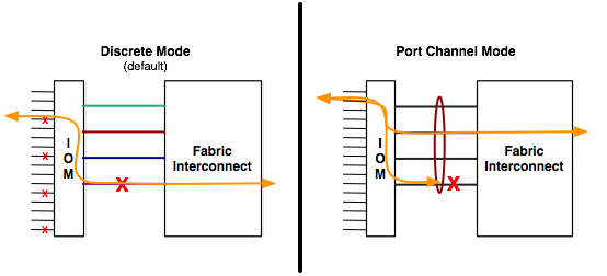
Cisco Unified Computing System – QoS and Jumbo Frames
FlexPod accommodates a myriad of traffic types (Cluster, SMB, iSCSI, control traffic, etc.) and is capable of absorbing traffic spikes and protect against traffic loss. Cisco UCS QoS system classes and policies can be configured to deliver this functionality. In this validation effort the FlexPod was configured to support jumbo frames with an MTU size of 9000. Enabling jumbo frames allows the FlexPod environment to optimize throughput between devices while simultaneously reducing the consumption of CPU resources.
![]() Note: When setting up Jumbo frames, it is important to make sure MTU settings are applied uniformly across the stack to prevent packet drops and negative performance.
Note: When setting up Jumbo frames, it is important to make sure MTU settings are applied uniformly across the stack to prevent packet drops and negative performance.
Windows Server 2016 Hyper-V
Windows Server 2016 is the latest version of Microsoft server operating system. It is a cloud-ready server operating system designed to run both traditional and cloud-native workloads whether on-premises, in a hybrid environment, or in any public environment equally well using the new capabilities such as Windows Server Containers and the lightweight Nano Server.
Windows Server 2016 comes in three editions - Datacenter, Standard and Essentials. Datacenter edition comes with unlimited virtualization along with new features including Shielded Virtual Machines, Software-Defined Storage and Software-Defined Networking. Standard edition comes with limited virtualization and the Essentials edition is for small-to-medium sized customers with up to 50 users.
Hyper-V is Microsoft's virtualization product. The Hyper-V server role in Windows Server enables you to create a virtualized server computing environment where you can create and manage virtual machines. It allows you to install and run multiple operating systems independently and in isolation on one physical computer.
The following table compares the maximum configuration for the various components that apply to Windows Server 2012 R2 and Windows Server 2016.
| System |
Components |
Windows Server 2012 R2 |
Windows Server 2016 |
| Physical Server (Host) |
Memory per host |
4 TB |
24 TB |
|
|
Logical processors per host |
320 |
512 |
|
|
Virtual processors per host |
2048 |
2048 |
|
|
Virtual machines per host |
1024 |
1024 |
| Virtual Machine |
Memory support per VM |
1 TB |
12 TB |
|
|
Virtual processors per VM |
64 |
240 |
|
|
Virtual disk capacity |
64 TB |
64 TB |
|
|
Virtual SCSI disks |
256 |
256 |
| Cluster |
Nodes per cluster |
64 |
64 |
|
|
VMs per cluster |
8000 |
8000 |
New features for Windows Server 2016 Hyper-V include:
· Hyper-V is a supported role on Nano Server
· Windows containers
· Shielded Virtual Machines (see Security section of this document)
· Virtualization Based Security
· Virtual Machine Resiliency
· Production checkpoints
· Cluster OS Rolling Upgrade for Hyper-V clusters
· Storage Quality of Service (QoS)
· PowerShell Direct
· Compatible with Connected Standby
· Discrete device assignment
· Hot add and remove for network adapters
· Hot add and remove for fixed memory
Hyper-V Manager improvements are as follows:
· Integration services delivered through Windows Update
· Linux Secure Boot
· Nested virtualization
· Networking features
· Updated virtual machine file formats
· Allow running down-level virtual machines
Microsoft System Center 2016 Virtual Machine Manager
Virtual machine manager, a part of the Microsoft System Center suite, is a virtualization and cloud management platform. It allows an administrator to configure and manage the servers, network, and storage resources. With SCVMM, you can manage your applications and services across multiple hypervisors and across hybrid cloud infrastructure to deliver flexible and cost-effective IT services. It includes the following capabilities:
· Datacenter: Configure and manage your datacenter components as a single fabric in VMM. Datacenter components include virtualization servers, networking components, and storage resources. VMM provisions and manages the resources needed to create and deploy virtual machines and services to private clouds.
· Virtualization hosts: VMM can add, provision, and manage Hyper-V and VMware virtualization hosts and clusters.
· Networking: Add networking resources to the VMM fabric, including network sites defined by IP subnets, virtual LANs (VLANs), logical switches, static IP address and MAC pools. VMM provides network virtualization, including support for creating and manage virtual networks and network gateways. Network virtualization allows multiple tenants to have isolated networks and their own IP address ranges for increased privacy and security. Using gateways, VMs on virtual networks can connect to physical networks in the same site or in different locations.
· Storage: VMM can discover, classify, provision, allocate, and assign local and remote storage. VMM supports block storage (fibre channel, iSCSI, and Serial Attached SCSI (SAS) storage area networks (SANs)).
· Library resources: The VMM fabric retains a library of file-based and non-file based resources that are used to create and deploy VMs and services on virtualization hosts. File-based resources include virtual hard disks, ISO images, and scripts. Non file-based resources include templates and profiles that are used to standardize the creation of VMs. Library resources are accessed through library shares.
Microsoft System Center 2016 Operation Manager
Operations Manager, a component of Microsoft System Center suite, provides infrastructure monitoring that is flexible and cost-effective. It enables you to monitor services, devices, and operations for many computers in a single console. Operators can gain rapid insight into the state of the IT environment and the IT services running across different systems and workloads by using numerous views that show state, health, and performance information, as well as alerts generated for availability, performance, configuration, and security situations. For detailed information, see https://docs.microsoft.com/en-us/system-center/scom/welcome
Cisco UCS Management and Microsoft System Center Integration
The Cisco Unified Computing System™ (Cisco UCS™) with its underlying programmable technology and management tools integrates with Microsoft systems management offerings to help optimize operations. You can simplify the tool set needed to monitor and manage bare-metal, virtualized, and cloud environments. With Cisco UCS and Microsoft integration, you can boost operation efficiency and improve visibility and control.
Cisco and Microsoft have jointly developed and enhanced management packs for Microsoft System Center Operations Manager (SCOM) and PowerShell, so you can automate data center setup, provisioning, and management. This programmatic control is central to the provisioning of hybrid cloud infrastructure to enable self-service provisioning.
Cisco UCS Management Suite for Microsoft SCOM
A management pack is a definition file with predefined monitoring settings that enables you to monitor a specific service or application in an operations manager. The Cisco UCS Management Pack Suite for Microsoft System Center Operations Manager is a set of management packs that provide visibility into the health, performance, and availability of Cisco UCS servers managed by Cisco UCS Manager, Cisco UCS Central Software, and Cisco® Integrated Management Controller (IMC). Cisco UCS Manager provides embedded management for all software and hardware components in Cisco UCS. It supports Cisco UCS B-Series Blade Servers, C-Series Rack Servers, and S-Series Storage Servers; Cisco UCS Mini, and Cisco HyperFlex™ hyperconverged infrastructure. The IMC supports Cisco UCS C-Series servers in standalone environments.
In addition to monitoring the health of Cisco UCS, you can do the following:
· View Cisco UCS physical and virtual resources, service profiles, operating systems, and virtual machines (VMs).
· Correlate faults and events between Cisco UCS infrastructure and both bare-metal and virtualized OSs that you manage with SCOM.
· Visually correlate blades, service profiles, and host OSs by using SCOM status views to quickly determine the way an event will affect the overall system
Cisco UCS PowerTool Suite
The Cisco UCS PowerTool Suite consists of a set of Microsoft Windows PowerShell modules for Cisco UCS Manager, Cisco IMC, and Cisco UCS Central Software that helps you configure and manage Cisco UCS domains and solutions. This command-line toolkit is based on PowerShell and is used to automate and integrate Cisco UCS management with Microsoft servers and applications. The Cisco UCS PowerTool module for Cisco UCS Manager includes over 1,970 cmdlets. In addition, by using Cisco UCS PowerTool together with similar management tools based on PowerShell from third-party vendors, you can manage and operate all components programmatically
Cisco UCS Manager Add-In for Microsoft System Center Virtual Machine Manager
Cisco UCS Manager Add-in for SCVMM provides an extension to the Virtual Machine Manager user interface. The extended interface enables you to manage the Cisco UCS servers (blade servers and rack-mount servers). You can perform the following tasks using the extension:
· Viewing and acknowledging pending activities
· Mapping of the hypervisor host with the blades or rack servers on which it is installed
· Adding or removing a Cisco UCS domain
· Viewing the server details
· Assigning proxy settings to the domain
· Viewing the firmware details of a server
· Viewing the fault information
· Viewing service profiles and service profile templates details
· Viewing the registered Cisco UCS domains details
· Launching the host (server) KVM console
· Managing the desired power state of the servers
· Switching on and off of the locator LEDs
· Associating service profile to a server
· Associating service profile to a server pool
· Changing the service profile association with a host firmware package
· Disassociating a service profile from a server
· Creating a service profile from a service profile template
· Uploading and upgrading the firmware on the servers
For more information, see:
Management and Best Practices with Windows 2016 Hyper-V
The Microsoft ecosystem of products and third-party solutions affords a plethora of options when it comes to management, orchestration, monitoring and back-ups. This section details some of those choices and best practice considerations.
NetApp Host Utilities Kit
The Host Utilities are a set of software programs and documentation that enable you to connect host computers to virtual disks (LUNs) on NetApp storage systems. The Host Utilities Kit installer sets timeouts and other operating system–specific values to their recommended default values. It also installs utility programs for managing LUNs that reside on NetApp storage. See the NetApp Interoperability Matrix Tool for complete details for a given NetApp tested and supported configuration.
For the FlexPod solution with Hyper-V the latest version of the Windows Host Utilities kit for Hyper-V is installed.
Host Multi-pathing
The Host Utilities can be used to support multiple paths, including a combination of protocols between the host and storage controllers. Configuring multiple paths can provide a highly available connection between the Windows host and storage system.
Multipath I/O (MPIO) software is required any time a Windows host has more than one path to the storage system. The MPIO software presents a single disk to the operating system for all paths, and a device-specific module (DSM) manages path failover. Without MPIO software, the operating system might see each path as a separate disk, which can lead to data corruption.
There is a native DSM provided with Microsoft Windows Server 2008, Windows Server 2008 R2, Windows Server 2012, Windows Server 2012 R2, and Windows Server 2016. It offers active/active and active/passive load balance policies for both the FC and iSCSI protocols. ALUA must be enabled on the storage system interface groups.
NetApp SnapDrive for Windows
SnapDrive for Windows enables you to automate storage provisioning tasks and to manage data in Microsoft Windows environments. You can run SnapDrive on Windows hosts in either a physical or virtual environment.
Several components are integrated into the SnapDrive software and are automatically installed. These components enable you to manage LUNs. You can use these components together to enable SnapDrive workflows, including provisioning, Snapshot copy management, backup, restore, and mounting operations.
The following SnapDrive components are integrated in the software and are automatically installed during installation.
· SnapDrive "snap-in"
· SnapDrive command-line interface
· PowerShell cmdlets
· Underlying SnapDrive service
· Data ONTAP Volume Shadow Copy Service (VSS) Hardware Provider on Windows Server hosts
System Center Virtual Machine Manager (SCVMM)
In Microsoft® System Center Virtual Machine Manager (SCVMM) 2016, you can discover, classify, and provision remote storage on supported storage arrays through the VMM console. VMM fully automates the assignment of storage to a Hyper-V® host or Hyper-V host cluster and tracks the storage that is managed by SCVMM. To enable the new storage features, SCVMM 2016 uses the Microsoft Storage Management Service to communicate with the external arrays through a Storage Management Initiative Specification (SMI-S) agent. The Storage Management Service is installed by default during the installation of SCVMM 2016.
NetApp SMI-S Agent
The NetApp Data ONTAP SMI-S Agent allows administrators to manage and monitor NetApp FAS storage systems through open-standard protocols and classes as defined by two organizations:
· Distributed Management Task Force (DMTF)
· Storage Networking Industry Association (SNIA)
The Data ONTAP Storage Management Initiative Specification (SMI-S) Agent is a command-based interface that detects and manages platforms that run NetApp Data ONTAP. The SMI-S Agent uses web- based enterprise management protocols, which allow you to manage, monitor, and report on storage elements. The SMI-S integration is designed to:
· Allow end-to-end discovery of logical and physical objects and the associations between them
· Add capacity to hosts and clusters
· Rapidly provision VMs by using the SAN and the SMB 3.0 protocol
The SMI-S Agent interface can also be used to accomplish simple tasks. Administrators can use Microsoft System Center Virtual Machine Manager (SCVMM) to create and deploy new storage to individual hosts or clusters. Compliance with SMI-S standards is defined by the Conformance Test Program and set by SNIA.
NetApp OnCommand Plug-in for Microsoft
NetApp® OnCommand® Plug-in for Microsoft integrates with Microsoft® System Center 2016 management of NetApp storage. The NetApp OnCommand Plug-in for Microsoft allows administrators to:
· Monitor server and storage availability and capacity for Microsoft Windows Server® Hyper-V virtual machines (VMs)
· Isolate problems using System Center Operations Manager (SCOM) alerts and health explorer views
· Enable high availability and load balancing of management servers with OpsMgr Management Server Resource Pool
· Leverage System Center Virtual Machine Manager and System Center Orchestrator for workflow automation
· Report on clustered Data ONTAP® MetroCluster storage
OnCommand Plug-in for Microsoft enables administrators to discover and monitor NetApp SAN and SMB shares. You can use the included Virtualization Pack to discover and monitor Windows Server Hyper-V VMs and alert VM administrators of potential storage issues.
SCVMM versus CLI
VMM cmdlets
Cmdlets not only enable automation of repeatable actions but also standardize the workflows. All the tasks in SCVMM can also be accomplished using cmdlets. The SCVMM cmdlets can be invoked directly using VMM command shell or importing the VMM module to Windows powershell manually. Each cmdlet noun is preceded with an “SC”. For example, Install-SCVMHostCluster creates a failover-cluster from Hyper-V hosts. Additionally Hyper-V specific cmdlets, enable creating and managing virtual machine resources. For example, Add-VMNetworkAdapter enables adding virtual network adapter to a virtual machine.
SnapManager for Hyper-V
SnapManager for Hyper-V provides a solution for data protection and recovery for Microsoft® Hyper-V virtual machines running on the NetApp Data ONTAP® operating system. You can perform application-consistent and crash-consistent dataset backups according to protection policies set by your backup administrator. You can also restore VMs from these backups. Reporting features enable you to monitor the status of and get detailed information about your backup and restore jobs.
Key benefits:
· Simplified, automated backup, restores, and replication of virtual machines
· Increased operational efficiency with built-in backup scheduler and policy-based retention
· Simplified user experience for users familiar with Microsoft Management Console (MMC) interface
· Support across Fibre Channel, iSCSI, and SMB 3.0 protocols
OnCommand Workflow Automation Pack for ACI
NetApp’s OnCommand Workflow Automation (WFA) tool has been extended, to include interacting with Cisco ACI APICs. WFA provides a management framework and command and workflow libraries (organized into modular “packs”, that contain related functionality) to automate NetApp storage management tasks, such as provisioning, migration, decommissioning, data protection configurations, and cloning storage. The WFA Pack for ACI extends WFA to include APICs, bridging the automation gap between storage and network. The WFA Pack for ACI is discussed in detail in NetApp Technical Report TR-4588, which is available here: http://www.netapp.com/us/media/tr-4588.pdf
This Technical Report:
· Discusses how to obtain the pack, and import it into a WFA instance
· Shows how to connect the WFA instance to an ACI APIC
· Examines the new ACI-related commands, explaining how they work, and offers tips on how to use them:
- Create Storage Contract
- Remove Storage Contracts
- Create EPG
- Remove EPG
- Provide Storage Contract
- Consume Storage Contract
- Create VPC Bundle
- Create Port Specific VPC Bundle
- Add VLAN Bundle
- Delete VLAN Bundle
· Examines the workflows that are included in the pack, explaining how they work:
- Create Storage Contracts
- Remove Storage Contracts
- Add VLAN tagged ifgrp to tn/app/epg
- Remove VLAN tagged ifgrp from tn/app/epg
- Provide Storage Contract
- Consume Storage Contract
· Shows how to build two custom workflows using the WFA Designer, that configure both ONTAP and ACI components:
- Add ifgrp/vPC
- Add LUN with iSCSI Access
A high level summary of the FlexPod Datacenter Design validation is provided in this section. The solution was validated for basic data forwarding by deploying virtual machines running the IOMeter tool. The system was validated for resiliency by failing various aspects of the system under load. Examples of the types of tests executed include:
· Failure and recovery of network paths to AFF nodes, ACI switches, and fabric interconnects.
· SSD removal to trigger an aggregate rebuild.
· Storage link failure between one of the AFF nodes and the ACI fabric.
· Storage controller failure and takeover by surviving controller.
Validated Hardware and Software
Table 3 describes the hardware and software versions used during solution validation. It is important to note that Cisco, NetApp, and Microsoft have interoperability matrixes that should be referenced to determine support for any specific implementation of FlexPod. Click the following links for more information:
· NetApp Interoperability Matrix Tool
· Cisco UCS Hardware and Software Interoperability Tool
Table 3 Validated Hardware and Software Versions
| Layer |
Device |
Image |
Comments |
| Compute |
Cisco UCS Fabric Interconnects 6300 Series, UCS B-200M5, UCS B-200 M4, UCS C-220 M4 |
3.2(1d) |
|
| Network |
Cisco ACI |
APIC 3.0(1k) Switches n9000-13.0(1k) |
|
| Storage |
NetApp AFF A300 |
ONTAP 9.1 |
|
| Software |
Cisco UCS Manager |
3.2(1d) |
|
|
|
Cisco UCS Manager Plugin for SCVMM
|
1.1.2 |
|
|
|
NetApp SnapDrive |
7.1.4 |
|
|
|
NetApp OnCommand Unified Manager |
7.2 |
|
FlexPod Datacenter with Cisco ACI and Microsoft Windows Hyper-V 2016 is the optimal shared infrastructure foundation to deploy a variety of IT workloads that is future proofed with 16 Gb/s FC or 40Gb/s iSCSI, with either delivering 40Gb Ethernet connectivity. Cisco and NetApp have created a platform that is both flexible and scalable for multiple use cases and applications. From virtual desktop infrastructure to SAP®, FlexPod can efficiently and effectively support business-critical applications running simultaneously from the same shared infrastructure. The flexibility and scalability of FlexPod also enable customers to start out with a right-sized infrastructure that can ultimately grow with and adapt to their evolving business requirements.
Products and Solutions
Cisco Unified Computing System:
http://www.cisco.com/en/US/products/ps10265/index.html
Cisco UCS 6300 Series Fabric Interconnects:
Cisco UCS 5100 Series Blade Server Chassis:
http://www.cisco.com/en/US/products/ps10279/index.html
Cisco UCS B-Series Blade Servers:
http://www.cisco.com/en/US/partner/products/ps10280/index.html
Cisco UCS C-Series Rack Mount Servers:
http://www.cisco.com/c/en/us/products/servers-unified-computing/ucs-c-series-rack-servers/index.html
Cisco UCS Adapters:
http://www.cisco.com/en/US/products/ps10277/prod_module_series_home.html
Cisco UCS Manager:
http://www.cisco.com/en/US/products/ps10281/index.html
Cisco UCS Manager Plug-in for VMware vSphere Web Client:
Cisco Nexus 9000 Series Switches:
http://www.cisco.com/c/en/us/products/switches/nexus-9000-series-switches/index.html
NetApp ONTAP 9:
http://www.netapp.com/us/products/platform-os/ontap/index.aspx
NetApp AFF A300:
http://www.netapp.com/us/products/storage-systems/all-flash-array/aff-a-series.aspx
NetApp OnCommand:
http://www.netapp.com/us/products/management-software/
NetApp SnapManager:
http://www.netapp.com/us/products/management-software/snapmanager/
Interoperability Matrixes
Cisco UCS Hardware Compatibility Matrix:
https://ucshcltool.cloudapps.cisco.com/public/
VMware and Cisco Unified Computing System:
http://www.vmware.com/resources/compatibility
NetApp Interoperability Matrix Tool:
http://support.netapp.com/matrix/
John George, Technical Marketing Engineer, Data Center Solutions Engineering, Cisco Systems Inc.
John has been designing, developing, validating, and supporting the FlexPod Converged Infrastructure for over seven years. Before his roles with FlexPod, he supported and administered a large worldwide training network and VPN infrastructure. John holds a Master's degree in Computer Engineering from Clemson University.
Dave Derry, Technical Marketing Engineer, Converged Infrastructure Engineering, NetApp Inc.
Dave Derry is a Technical Marketing Engineer in the NetApp Converged Infrastructure Engineering team. He focuses on producing validated reference architectures that promote the benefits of end-to-end data center solutions and cloud environments.
Acknowledgements
For their support and contribution to the design, validation, and creation of this Cisco Validated Design, the authors would like to thank:
· Haseeb Niazi, Cisco Systems, Inc.
· Sanjeev Naldurgkar, Cisco Systems, Inc.
· Rajendra Yogendra, Cisco Systems, Inc.
· Lindsey Street, NetApp
 Feedback