FlexPod Datacenter with Microsoft Private Cloud Fast Track 4.0 and Cisco Nexus 9000 Series Switches Design Guide
Available Languages
FlexPod Datacenter with Microsoft Private Cloud Fast Track 4.0 and Cisco Nexus 9000 Series Switches Design Guide
First Published: June 12, 2015
Last Updated: June 12, 2015

About Cisco Validated Designs
The CVD program consists of systems and solutions designed, tested, and documented to facilitate faster, more reliable, and more predictable customer deployments. For more information visit
http://www.cisco.com/go/designzone.
ALL DESIGNS, SPECIFICATIONS, STATEMENTS, INFORMATION, AND RECOMMENDATIONS (COLLECTIVELY, "DESIGNS") IN THIS MANUAL ARE PRESENTED "AS IS," WITH ALL FAULTS. CISCO AND ITS SUPPLIERS DISCLAIM ALL WARRANTIES, INCLUDING, WITHOUT LIMITATION, THE WARRANTY OF MERCHANTABILITY, FITNESS FOR A PARTICULAR PURPOSE AND NONINFRINGEMENT OR ARISING FROM A COURSE OF DEALING, USAGE, OR TRADE PRACTICE. IN NO EVENT SHALL CISCO OR ITS SUPPLIERS BE LIABLE FOR ANY INDIRECT, SPECIAL, CONSEQUENTIAL, OR INCIDENTAL DAMAGES, INCLUDING, WITHOUT LIMITATION, LOST PROFITS OR LOSS OR DAMAGE TO DATA ARISING OUT OF THE USE OR INABILITY TO USE THE DESIGNS, EVEN IF CISCO OR ITS SUPPLIERS HAVE BEEN ADVISED OF THE POSSIBILITY OF SUCH DAMAGES.
THE DESIGNS ARE SUBJECT TO CHANGE WITHOUT NOTICE. USERS ARE SOLELY RESPONSIBLE FOR THEIR APPLICATION OF THE DESIGNS. THE DESIGNS DO NOT CONSTITUTE THE TECHNICAL OR OTHER PROFESSIONAL ADVICE OF CISCO, ITS SUPPLIERS OR PARTNERS. USERS SHOULD CONSULT THEIR OWN TECHNICAL ADVISORS BEFORE IMPLEMENTING THE DESIGNS. RESULTS MAY VARY DEPENDING ON FACTORS NOT TESTED BY CISCO.
CCDE, CCENT, Cisco Eos, Cisco Lumin, Cisco Nexus, Cisco StadiumVision, Cisco TelePresence, Cisco WebEx, the Cisco logo, DCE, and Welcome to the Human Network are trademarks; Changing the Way We Work, Live, Play, and Learn and Cisco Store are service marks; and Access Registrar, Aironet, AsyncOS, Bringing the Meeting To You, Catalyst, CCDA, CCDP, CCIE, CCIP, CCNA, CCNP, CCSP, CCVP, Cisco, the Cisco Certified Internetwork Expert logo, Cisco IOS, Cisco Press, Cisco Systems, Cisco Systems Capital, the Cisco Systems logo, Cisco Unity, Collaboration Without Limitation, EtherFast, EtherSwitch, Event Center, Fast Step, Follow Me Browsing, FormShare, GigaDrive, HomeLink, Internet Quotient, IOS, iPhone, iQuick Study, IronPort, the IronPort logo, LightStream, Linksys, MediaTone, MeetingPlace, MeetingPlace Chime Sound, MGX, Networkers, Networking Academy, Network Registrar, PCNow, PIX, PowerPanels, ProConnect, ScriptShare, SenderBase, SMARTnet, Spectrum Expert, StackWise, The Fastest Way to Increase Your Internet Quotient, TransPath, WebEx, and the WebEx logo are registered trademarks of Cisco Systems, Inc. and/or its affiliates in the United States and certain other countries.
All other trademarks mentioned in this document or websites are the property of their respective owners. The use of the word partner does not imply a partnership relationship between Cisco and any other company. (0809R)
© 2015 Cisco Systems, Inc. All rights reserved.
Table of Contents
Private Cloud Fast Track Program
Program Requirements and Validation
Core Fast Track Infrastructure
Cisco Unified Computing System
Cisco UCS B200 M4 Blade Servers
Cisco UCS 1340 Virtual Interface Card
Cisco UCS 6248UP Fabric Interconnect
Cisco Nexus 1100 Series Cloud Services Platform (CSP)
NetApp FAS and Clustered Data ONTAP
Storage Options for Windows Server 2012 R2
SMB 3.0 Continuously Available File Shares
Windows Server 2012 R2─Hyper-V
Microsoft System Center 2012 R2
System Center Operations Manager
System Center Virtual Machine Manager
The Microsoft Private Cloud Fast Track program is a joint effort between Microsoft and two of its hardware partners Cisco and NetApp. The goal of the program is to help organizations develop and implement a private cloud solution quickly while reducing complexity and risk. The program provides a reference architecture that combines Microsoft software, consolidated guidance, and validated configurations with partner technology such as compute, network, and storage architectures, in addition to value-added software components.
The private cloud model provides much of the efficiency and agility of cloud computing, along with the increased control and customization that are achieved through dedicated private resources. By implementing Private Cloud Fast Track, Microsoft and its hardware partners can help provide organizations with the control and the flexibility necessary to reap the potential benefits of the private cloud.
Private Cloud Fast Track utilizes the core capabilities of the Windows Server (OS), Hyper-V, and System Center to deliver a private cloud infrastructure as a service offering; these are also the key software components used for every reference implementation.
Private Cloud Fast Track Program
The Infrastructure as a Service (IaaS) Product Line Architecture (PLA) focuses on deploying virtualization fabric and fabric management technologies in Windows Server and System Center to support private cloud scenarios. This PLA includes reference architectures, best practices, and processes for streamlining deployment of these platforms to support private cloud scenarios.
This component of the IaaS PLA delivers core foundational virtualization fabric infrastructure guidance that aligns to the defined architectural patterns within this and other Windows Server 2012 R2 private cloud programs. The resulting Hyper-V infrastructure in Windows Server 2012 R2 can be leveraged to host advanced workloads, and subsequent releases will contain fabric management scenarios using System Center components. Scenarios relevant to this release include:
· Resilient infrastructure – Maximize the availability of IT infrastructure through cost-effective redundant systems that prevent downtime, whether planned or unplanned.
· Centralized IT – Create pooled resources with a highly virtualized infrastructure that supports maintaining individual tenant rights and service levels.
· Consolidation and migration – Remove legacy systems and move workloads to a scalable high-performance infrastructure.
· Preparation for the cloud – Create the foundational infrastructure to begin transition to a private cloud solution.
Each branch in the Fast Track program uses a reference architecture that defines the requirements that are necessary to design, build, and deliver virtualization and private cloud solutions for small, medium, and large-size enterprise implementations. Size is measured in the number of generic virtual machines. The size of the virtual machines will vary from customer to customer, so use the numbers as relative numbers. The small and medium solutions will handle up to 75 virtual machines. The large solution is designed to handle up to 8,000 virtual machines.
Each reference architecture in the Fast Track program combines guidance with validated configurations for the compute, network, storage, and virtualization layers. These architectures present multiple design patterns for enabling the architecture, and each design pattern describes the minimum requirements for validating each Fast Track solution.
The FlexPod Fast Track Solution presented here is a large solution. The FlexPod with Microsoft Private Cloud Fast Track solution utilizes the core capabilities of Windows Server 2012 R2, Hyper-V, and System Center 2012 R2 to deliver a Private Cloud - Infrastructure as a Service offering. The key software components of every Reference implementation are Windows Server 2012 R2, Hyper-V, and System Center 2012 R2. The solution also includes software from Cisco and NetApp to form a complete solution that is ready for your enterprise.
Business Value
The FlexPod with Microsoft Private Cloud Fast Track solution provides reference architecture for building private clouds on each organization’s unique terms. Each Fast-Track solution helps organizations implement private clouds with increased ease and confidence. Among the benefits of the Microsoft Private Cloud Fast Track Program are faster deployment, reduced risk, and a lower cost of ownership.
Reduced risk:
· Tested end-to-end interoperability of compute, storage, and network
· Predefined, out-of-the box solutions based on a common cloud architecture that has already been tested and validated
· High degree of service availability through automated load balancing
Lower cost of ownership:
· A cost-optimized, platform and software-independent solution for rack system integration
· High performance and scalability with Windows Server 2012 R2 operating system with Hyper-V
· Minimized backup times and fulfilled recovery time objectives for each business critical environment
· Highly scalable to address changing business needs
— Eight Cisco UCS B200 M4 servers as the initial configuration. Expand by adding another chassis with eight more Cisco UCS B200 M4 servers, or other B-series blades, depending on specific needs
— NetApp Clustered Data ONTAP, offering both the ability to non-disruptively scale-up and out to meet any needs.
Technical Benefits
The Microsoft Private Cloud Fast Track Program integrates the best-in-class hardware implementations with Microsoft’s software to create a Reference Implementation. This solution has been co-developed with Cisco, NetApp, and Microsoft and has gone through a validation process. As a Reference Implementation, Cisco, NetApp, and Microsoft have done the work of building a private cloud that is ready to meet a customer’s needs.
Faster deployment:
· End-to-end architectural and deployment guidance
· Streamlined infrastructure planning due to predefined capacity
· Enhanced functionality and automation through deep knowledge of infrastructure
· Integrated management for virtual machine (VM) and infrastructure deployment
· Self-service portal for rapid and simplified provisioning of resources
Program Requirements and Validation
The Microsoft Private Cloud Fast Track program is comprised of three pillars; Engineering, Marketing and Enablement. These three pillars drive the creation of the Reference implementations, making them public and making them available for customers to purchase. This Reference Architecture is one step in the “Engineering” phase of the program and towards the validation of a Reference implementation.
FlexPod Technology Overview
Industry trends indicate a vast data center transformation toward shared infrastructure and cloud computing. Enterprise customers are moving away from isolated centers of IT operation toward more cost-effective virtualized environments.
The objective of the move toward virtualization, and eventually to cloud computing, is to increase agility and reduce costs.
Since companies must address resistance to change in both their organizational and technical IT models, achieving this transformation can seem daunting and complex. To accelerate the process and simplify the evolution to a shared cloud infrastructure, Cisco and NetApp have developed a solution called FlexPod for Microsoft Private Cloud Fast Track v4.
FlexPod is a predesigned, best practice data center architecture that is built on Cisco Unified Computing System (Cisco UCS), the Cisco Nexus family of switches, and NetApp fabric-attached storage (FAS) or V-Series systems (see Figure 1). FlexPod is a suitable platform for running a variety of virtualization hypervisors as well as bare metal operating systems and enterprise workloads. FlexPod delivers not only a baseline configuration, but also the flexibility to be sized and optimized to accommodate many different use cases and requirements.
Figure 1 FlexPod Component Families
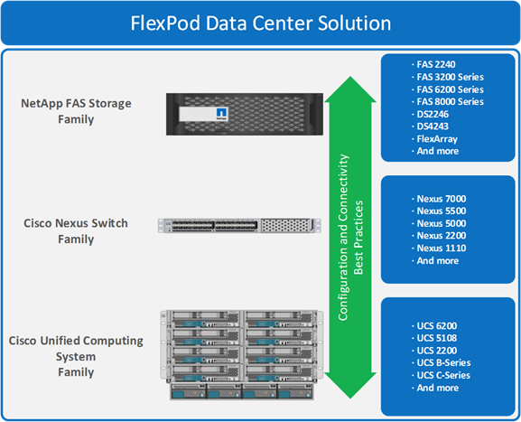
This document describes FlexPod Datacenter with Microsoft Private Cloud Fast Track v4 from Cisco and NetApp and discusses design choices and deployment best practices using this shared infrastructure platform.
The FlexPod solution is based on a converged infrastructure. Fabric Management virtual machines are hosted directly on a compute fabric cluster. Other workload or tenant virtual machines are deployed on a second compute cluster. Additional failover clusters can be configured for additional virtual machines, or the second cluster can be expanded up to 64 nodes. This solution starts with the minimum recommended number of System Center and Windows Azure Pack component servers in order to provide full functionality in a production environment. If needed, Component servers can be scaled-out by adding additional servers running the particular management component.
This design pattern is introduced for Fabric Management to include a dedicated four node Hyper-V failover cluster to host the fabric management virtual machines. This design pattern utilizes scaled-out and highly available deployments of the System Center components to provide full functionality in a production environment. In addition to the System Center components running as virtual machines, Cisco deploys a pair of Cisco Nexus 1000V virtual machines to handle network management for the virtual machines. An additional pair of virtual machines running the Cisco NetScaler 1000V provides load balancing.
Figure 2 Private Cloud Fabric Management Infrastructure
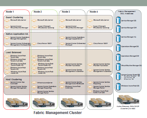
The Fabric Management cluster is configured to help ensure the maximum availability of all components of the environment. Each Cisco UCS B200 M4 blade server is configured with sufficient memory to support the running of all the listed virtual machines illustrated in Figure 3. By provisioning four nodes, the environment retains its high available capability even during those periods of time when the host nodes are individually taken down for maintenance. For example, in Figure 3, if Node 3 were down for maintenance, a catastrophic failure of Node 2 would not prevent all the virtual machines from continuing to run on Node 1 and Node 4.
Architecture
The FlexPod architecture is highly modular. Although each customer’s components might vary in its exact configuration, after a FlexPod configuration is built, it can easily be scaled as requirements and demands change. This includes both scaling up (adding additional resources within a Cisco UCS chassis and/or NetApp FAS 8000 series array) and scaling out (adding additional Cisco UCS chassis and/or NetApp FAS 8000 series array).
The Cisco UCS solution validated with Microsoft Private Cloud includes NetApp FAS 8040 storage array, Cisco Nexus 9300 Series network switches, the Cisco Unified Computing System platforms, and Microsoft virtualization software in a single package. The computing and storage can fit in one data center rack with networking residing in a separate rack or deployed according to a customer’s data center design. Due to port density, the networking components can accommodate multiple configurations of this kind.
Figure 3 FlexPod Implementation Diagram
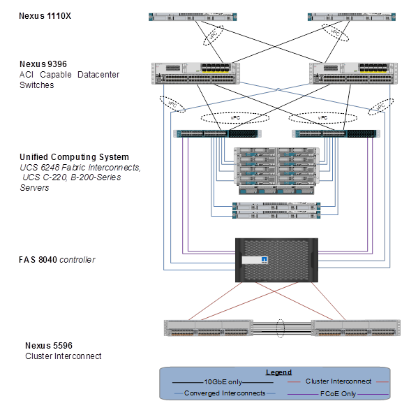
Figure 3 contains the following components:
· Cisco UCS 5108 chassis each with eight Cisco UCS B200 M4 Blade Servers
— Dual Intel E5-2660 V3 2.50 GHz processors
— 256 GB memory
— 1340 Virtual Interface Card
· Two Cisco UCS 2108 fabric extenders per chassis
· Two Cisco UCS 6248UP Fabric Interconnects
· Two Cisco Nexus 9396PX Switches
· Two Nexus 1110-X CSP Appliances
· NetApp FAS8040 controller running Clustered Data ONTAP
· (Optional) Cisco UCS C220 M4 Rack servers for infrastructure
A NetApp FAS8040 storage controller with accompanying disk shelves provides the storage. All systems and fabric links feature redundancy, enabling an end-to-end high availability (HA) configuration within a single chassis. For server virtualization, the deployment includes Microsoft Hyper-V. Although this is the default base design, each of the components can be scaled to support specific business requirements. For example, more (or different) blades and chassis can be deployed to increase compute capacity; additional disk shelves can be deployed to improve I/O capacity and throughput; special hardware or software features can be added to introduce new features.
Deployment Guide
The implementation of this solution is documented in a separate document called FlexPod Datacenter with Microsoft Private Cloud Fast Track 4.0. This document can be found at the following link:
http://www.cisco.com/c/dam/en/us/td/docs/unified_computing/ucs/UCS_CVDs/flexpod_mspc40_cmode_n9k.pdf
Cisco Unified Computing System
The Cisco Unified Computing System combines Cisco UCS B-Series Blade Servers and C-Series Rack Servers with networking and storage access in a single converged system that simplifies management and delivers greater cost efficiency and agility with increased visibility and control. The Cisco UCS B200 M4 Blade Server delivers performance, versatility, and density without compromise. It addresses the broadest set of workloads, from IT and web infrastructure, through distributed database.
Cisco UCS B200 M4 Blade Servers
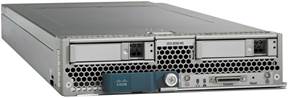
The Cisco UCS B200 M4 Blade Server (Figure 4) delivers performance, flexibility and optimization for data centers and remote sites. This enterprise-class server offers market-leading performance, versatility, and density without compromise for workloads ranging from web infrastructure to distributed databases. The Cisco UCS B200 M4 blade server can quickly deploy stateless physical and virtual workloads, with the programmable ease of use of the Cisco UCS Manager software and simplified server access with Cisco SingleConnect technology. Based on the Intel Xeon processor E5-2600 v3 product family, it offers up to 768 GB of memory using 32GB DIMMs, up to 2 drives, and up to 80 Gbps I/O throughput. The Cisco UCS B200 M4 blade server offers exceptional levels of performance, flexibility, and I/O throughput to run your most demanding applications.
Figure 4 Cisco UCS B200 M4 Blade Server
The Cisco UCS B200 M4 Blade Server provides:
· One or two, multi-core, Intel® Xeon® processor E5-2600 v3 series CPUs, for up to 36 processing cores
· 24 DIMM slots for industry-standard DDR4 memory running up to 2133 MHz and up to 768 GB of total memory when using 32-GB DIMMs
· Two optional, hot-pluggable SAS or SATA hard disk drives (HDDs) or solid-state drives (SSDs)
· Industry-leading 80 Gbps throughput bandwidth
· Remote management through a Cisco Integrated Management Controller (CIMC) that implements policy established in Cisco UCS Manager
· Out-of-band access by remote keyboard, video, and mouse (KVM) device, Secure Shell (SSH) Protocol, and virtual media (vMedia) as well as the Intelligent Platform Management Interface (IPMI)
In addition, the Cisco UCS B200 M4 blade server is a half-width blade (Figure 4). Up to eight of these high-density, two-socket blade servers can reside in the 6RU Cisco UCS 5108 Blade Server Chassis, offering one of the highest densities of servers per rack unit in the industry.
Cisco UCS 5108 Chassis
The Cisco UCS 5100 Series Blade Server Chassis is a crucial building block of the Cisco Unified Computing System, delivering a scalable and flexible blade server chassis for today’s and tomorrow’s data center while helping reduce TCO. The Cisco UCS 5108 Blade Server Chassis is six rack units (6RU) high and can mount in an industry-standard 19-inch rack. A chassis can house up to eight half-width Cisco UCS B-Series Blade Servers and can accommodate both half- and full-width blade form factors.
Four hot-swappable power supplies are accessible from the front of the chassis, and single-phase AC, –48V DC, and 200 to 380V DC power supplies and chassis are available. These power supplies are up to 94 percent efficient and meet the requirements for the 80 Plus Platinum rating. The power subsystem can be configured to support non-redundant, N+1 redundant, and grid-redundant configurations. The rear of the chassis contains eight hot-swappable fans, four power connectors (one per power supply), and two I/O bays that can support either Cisco UCS 2000 Series Fabric Extenders or the Cisco UCS 6324 Fabric Interconnect. A passive midplane provides up to 80 Gbps of I/O bandwidth per server slot and up to 160 Gbps of I/O bandwidth for two slots. The chassis is capable of supporting future 40 Gigabit Ethernet standards.
Figure 5 Cisco UCS 5108 Blade Server Chassis with Blade Servers Front and Back
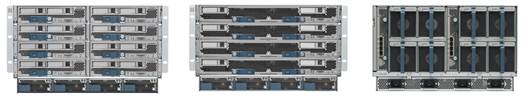
The Cisco UCS 5108 Blade Server Chassis revolutionizes the use and deployment of blade-based systems. By incorporating unified fabric, integrated, embedded management, and fabric extender technology, Cisco UCS allows the chassis to use fewer physical components, has no need for independent management, and enables greater energy efficiency than traditional blade server chassis. This simplicity eliminates the need for dedicated chassis management and blade switches, reduces cabling, and enables Cisco UCS to scale to 20 chassis without adding complexity. The Cisco UCS 5108 chassis is a critical component in delivering the Cisco UCS benefits of data center simplicity and IT responsiveness.
In addition, the Cisco UCS 5108 chassis has the architectural advantage of not having to power and cool excess switches in each chassis. With a larger power budget per blade server, Cisco can design uncompromised expandability and capabilities in its blade servers.
Cisco UCS 1340 Virtual Interface Card
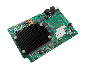
The Cisco UCS Virtual Interface Card (VIC) 1340 is a 2-port 40-Gbps Ethernet or dual 4 x 10-Gbps Ethernet, Fibre Channel over Ethernet (FCoE)-capable modular LAN on motherboard (mLOM) designed exclusively for the M4 generation of Cisco UCS B-Series Blade Servers. When used in combination with an optional port expander, the Cisco UCS VIC 1340 capabilities is enabled for two ports of 40-Gbps Ethernet.
The Cisco UCS VIC 1340 enables a policy-based, stateless, agile server infrastructure that can present over 256 PCIe standards-compliant interfaces to the host that can be dynamically configured as either network interface cards (NICs) or host bus adapters (HBAs). In addition, the Cisco UCS VIC 1340 supports Cisco® Data Center Virtual Machine Fabric Extender (VM-FEX) technology, which extends the Cisco UCS fabric interconnect ports to virtual machines, simplifying server virtualization deployment and management
Figure 6 Cisco UCS Virtual Interface Card (VIC) 1340
The personality of the card is determined dynamically at boot time using the service profile associated with the server. The number, type (NIC or HBA), identity (MAC address and World Wide Name [WWN]), failover policy, bandwidth, and quality-of-service (QoS) policies of the PCIe interfaces are all determined using the service profile. The capability to define, create, and use interfaces on demand provides a stateless and agile server infrastructure.
Figure 7 Cisco UCS Virtual Interface Card (VIC) 1340 Architecture
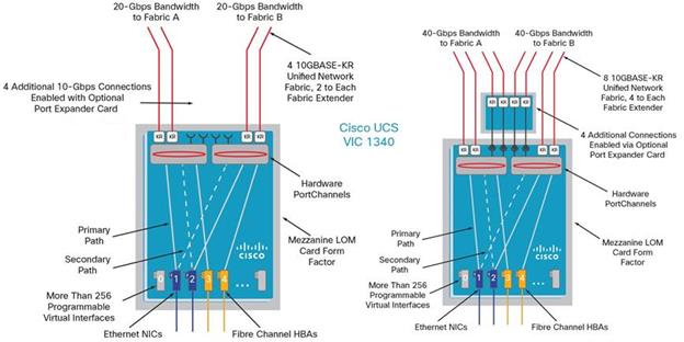
Each PCIe interface created on the VIC is associated with an interface on the Cisco UCS fabric interconnect, providing complete network separation for each virtual cable between a PCIe device on the VIC and the interface on the fabric interconnect.
Cisco UCS 6248UP Fabric Interconnect
The Cisco UCS 6200 Series is built to consolidate LAN and SAN traffic onto a single unified fabric, saving the capital expenditures (CapEx) and operating expenses (OpEx) associated with multiple parallel networks, different types of adapter cards, switching infrastructure, and cabling within racks. The unified ports support allows either base or expansion module ports in the interconnect to support direct connections from Cisco UCS to existing native Fibre Channel SANs. The capability to connect FCoE to native Fibre Channel protects existing storage system investments while dramatically simplifying in-rack cabling.
Figure 8 Cisco UCS 6248UP 48-Port Fabric Interconnect
The Cisco UCS 6248UP 48-Port Fabric Interconnect is a one-rack-unit (1RU) 10 Gigabit Ethernet, FCoE and Fiber Channel switch offering up to 960-Gbps throughput and up to 48 ports. The switch has 32 1/10-Gbps fixed Ethernet, FCoE and FC ports and one expansion slot (not required for this Fast Track solution).
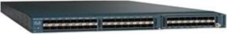
Cisco Nexus 9396PX Switch
With the Cisco Nexus 9000 Series, organizations can quickly and easily upgrade existing data centers to carry 40 Gigabit Ethernet to the aggregation layer through advanced and cost-effective optics that enable the use of existing 10 Gigabit Ethernet fiber (a pair of multimode fiber strands).
Cisco provides two modes of operation for the Cisco Nexus 9000 Series. Organizations can use Cisco NX-OS Software to deploy the Cisco Nexus 9000 Series in standard Cisco Nexus switch environments. This is the method of deployment for this Fast Track solution. Organizations also can use a hardware infrastructure that is ready to support Cisco Application Centric Infrastructure (ACI) to take full advantage of an automated, policy-based, systems management approach.
The Cisco Nexus 9300 platform consists of fixed-port switches designed for top-of-rack (ToR) and middle-of-row (MoR) deployment in data centers that support enterprise applications, service provider hosting, and cloud computing environments. The switches are Layer 2 and 3 nonblocking 10 and 40 Gigabit Ethernet switches with up to 2.56 terabits per second (Tbps) of internal bandwidth.
The switch series is compatible with integrated transceivers and Twinax cabling solutions that deliver cost-effective connectivity for 10 Gigabit Ethernet to servers at the rack level, eliminating the need for expensive optical transceivers. The Cisco Nexus 9000 Series portfolio also provides the flexibility to connect directly to servers using 10GBASE-T connections.
Figure 9 Cisco Nexus 9396PX Switch
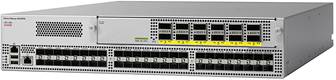
The Cisco Nexus 9396TX Switch is a 2RU switch that supports up to 1.92 Tbps of bandwidth and over 2700 Mpps across 48 fixed 1/10GBASE-T ports and an uplink module that can support up to 12 fixed 40-Gbps Enhanced Quad SFP (QSFP+) ports.
Cisco Nexus 1000V
Cisco Nexus1000V Switch provides a comprehensive and extensible architectural platform for virtual machine and cloud networking. The switch is designed to accelerate server virtualization and multitenant cloud deployments in a secure and operationally transparent manner.
The Cisco Nexus 1000V Switch for Microsoft Hyper-V is a distributed software switching platform for Microsoft Windows Server environments. It provides:
· Advanced Cisco NX-OS Software feature set and associated partner ecosystem
· Innovative network services architecture to support scalable, multitenant environments
· Consistent operating model across physical and virtual environments and across hypervisors
· Tight integration with Microsoft System Center Virtual Machine Manager
The Cisco Nexus 1000V Switch brings the robust architecture associated with traditional Cisco physical modular switches to Microsoft Hyper-V environments. The solution has two main components.
Figure 10 Cisco Nexus 1000V Switch for Microsoft Hyper-V Components
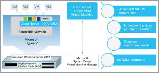
· The Cisco Nexus 1000V virtual Ethernet module (VEM) is a software component deployed on each Microsoft Hyper-V host as a forwarding extension. Each virtual machine on the host is connected to the VEM through virtual Ethernet (vEth) ports.
· The Cisco Nexus 1000V virtual supervisor module (VSM) is the management component that controls multiple VEMs and helps in the definition of virtual machine-focused network policies. It is a virtual machine running Cisco NX-OS on a Microsoft Hyper-V host and is similar to the supervisor module on a physical modular switch.
In addition to the VEM and VSM, Cisco Nexus 1000V Switches include Cisco vPath technology and provide a scalable, multitenant network services infrastructure for Microsoft Hyper-V environments.
The Cisco Nexus 1000V uses the extensible switch framework offered by Microsoft Windows Server 2012 R2 with Hyper-V and the management ecosystem offered by Microsoft SCVMM and thus provides a transparent operating experience for Microsoft Hyper-V environments.
Citrix NetScaler 1000V
Citrix NetScaler is the industry's leading web application delivery solution. It increases the performance and availability of all applications and data. Citrix NetScaler 1000V brings together Citrix NetScaler with Cisco Nexus® 1000V Switch vPath technology for policy-based service insertion and chaining. As of Citrix NetScaler 1000V Release 10.1-124.14, vPath can be disabled to load-balance physical servers or load-balance workloads running on any hypervisor. Consequently, the Cisco Nexus 1000V virtual distributed switch is also optional when you are not using vPath technology.
Citrix NetScaler 1000V runs on the Cisco Nexus 1110-X Cisco® Cloud Services Platform (CSP). An SSL offload card is also available for the Cisco Nexus 1110-X platform when high performance is needed.
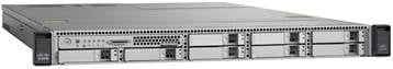
Cisco Nexus 1100 Series Cloud Services Platform (CSP)
The Cisco Nexus® 1100 Series Cloud Services Platforms (CSPs) offer dedicated hardware appliances for the deployment of network services critical to virtualized data center infrastructure (Figure 11). The appliances host a number of virtual service blades (VSBs), including the following:
· Cisco Nexus 1000V Virtual Supervisor Module (VSM), which acts as the control plane (VMware vSphere and Microsoft Hyper-V deployments)
· Cisco Virtual Security Gateway (VSG), which provides a firewall for east-west traffic (VMware vSphere and Microsoft Hyper-V deployments)
· Cisco Prime™ Network Analysis Module (NAM), which provides in-depth analytics
· Citrix NetScaler 1000V Application Delivery Controller (ADC)
These VSBs provide a comprehensive solution for virtual networking services in the data center. Dedicated hardware for the Cisco Nexus 1000V VSM eases virtual access switch deployment for the network administrator and with its support for additional VSBs, the Cisco Nexus 1100 Series CSPs are crucial components of a virtualized data center.
Figure 11 Cisco Nexus 1100 CSP
NetApp FAS and Clustered Data ONTAP
NetApp offers a unified storage architecture. The term “unified” refers to a family of storage systems that simultaneously support SAN (through FCoE, FC, and iSCSI) and network-attached storage (NAS) (through CIFS and NFS) across many operating environments, such as VMware®, Windows, and UNIX®. This single architecture provides access to data by using industry-standard protocols, including NFS, CIFS, iSCSI, FCP, SCSI, and NDMP. Connectivity options include standard Ethernet (10/100/1000Mb or 10GbE) and FC (1, 2, 4, or 8Gb/sec). In addition, all systems can be configured with high-performance solid-state drives (SSDs) or serial attached SCSI (SAS) disks for primary storage applications, low-cost SATA disks for secondary applications (backup, archive, and so on), or a mix of the different disk types.
A storage system running Data ONTAP, also known as the storage controller, is the hardware device that receives and sends data from the host. This unit detects and gathers information about its own hardware configuration, the storage system components, the operational status, hardware failures, and other error conditions.
A storage controller is highly redundantly connected to storage through disk shelves, which are the containers or device carriers that hold disks and associated hardware such as power supplies, connectivity interfaces, and cabling.
If storage requirements change over time, NetApp storage offers the flexibility to change quickly as needed without expensive and disruptive “forklift” upgrades. This applies to different types of changes:
· Physical changes, such as expanding a controller to accept more disk shelves and subsequently more hard disk drives (HDDs) without an outage
· Logical or configuration changes, such as expanding a RAID group to incorporate these new drives without requiring any sort of outage
· Access protocol changes, such as modifying a virtual representation of a hard drive to a host by changing a LUN from FC access to iSCSI access, with no data movement required, but only a simple dismount of the FC LUN and a mount of the same LUN, by using iSCSI
In addition, a single copy of data can be shared between Windows and UNIX systems while allowing each environment to access the data through native protocols and applications. In a system that was originally purchased with all SATA disks for backup applications, high-performance SAS disks could be added to support primary storage applications, such as Oracle®, Microsoft Exchange, or Microsoft SQL Server.
Clustered Data ONTAP expands this traditional flexibility by allowing the dynamic relocation of either the logical storage container or the volume through the Volume Move feature, as well as the reassignment of entire parity groups or aggregates through aggregate relocation. These features allow a truly nondisruptive architecture in which any component of the storage system can be upgraded, resized, or re-architected without disruption to the private cloud infrastructure.
NetApp storage solutions provide redundancy and fault tolerance through clustered storage controllers and hot-swappable redundant components, such as cooling fans, power supplies, disk drives, and shelves. This highly available and flexible architecture enables customers to manage all data under one common infrastructure while meeting mission-critical uptime requirements.
The storage efficiency built into Data ONTAP offers substantial space savings, allowing more data to be stored at lower cost. Data protection includes replication services, so that valuable data is backed up and recoverable from an alternate location. The following features provide storage efficiency and data protection:
· Thin provisioning. Volumes are created by using virtual sizing. They appear to be provisioned at their full capacity but are actually created much smaller and use additional space only when it is needed. Extra unused storage is shared across all volumes, and the volumes can grow and shrink on demand.
· Snapshot copies. Automatically scheduled point-in-time copies that write only changed blocks, with no performance penalty. Snapshot copies consume minimal storage space because only changes to the active file system are written. Individual files and directories can easily be recovered from any Snapshot copy, and the entire volume can be restored back to any Snapshot state in seconds.
· FlexClone volumes. Instant virtual copies of datasets that use near-zero space. The clones are writable, but only changes to the original are stored, so they provide rapid, space-efficient creation of additional data copies ideally suited for test and development environments.
· Deduplication. Removes redundant data blocks in primary and secondary storage with flexible policies to determine when the deduplication process is run.
· Compression. Compresses data blocks. Compression can be run whether or not deduplication is enabled and can provide additional space savings, whether run alone or together with deduplication.
· SnapMirror. SnapMirror® volumes can be asynchronously replicated either within the cluster or to another cluster.
All of these capabilities are then exposed through the logical management construct of a storage virtual machine (SVM), formerly known as Vserver.
Storage Virtual Machines
The secure logical storage partition through which data is accessed in clustered Data ONTAP is known as an SVM. A cluster serves data through at least one and possibly multiple SVMs. An SVM is a logical abstraction that represents a set of physical resources of the cluster. Data volumes and logical network interfaces (LIFs) are created and assigned to an SVM and can reside on any node in the cluster to which the SVM has been given access. An SVM can own resources on multiple nodes concurrently, and those resources can be moved nondisruptively from one node to another. For example, a flexible volume can be nondisruptively moved to a new node, and an aggregate, or a data LIF, can be transparently reassigned to a different physical network port. The SVM abstracts the cluster hardware and is not tied to specific physical hardware.
An SVM is capable of supporting multiple data protocols concurrently. Volumes within the SVM can be junctioned together to form a single NAS namespace, which makes all of an SVM’s data available to NFS and CIFS clients through a single share or mount point. For example, a 24-node cluster licensed for UNIX and Windows File Services that has a single SVM configured with thousands of volumes can be accessed from a single network interface on one of the nodes. SVMs also support block-based protocols, and LUNs can be created and exported by using iSCSI, FC, or FCoE. Any or all of these data protocols can be configured for use within a given SVM.
An SVM is a secure entity; therefore, it is aware of only the resources that have been assigned to it and has no knowledge of other SVMs and their respective resources. Each SVM operates as a separate and distinct entity with its own security domain. Tenants can manage the resources allocated to them through a delegated SVM administration account. Each SVM can connect to unique authentication zones, such as AD, LDAP, or NIS.
An SVM is effectively isolated from other SVMs that share the same physical hardware.
From a performance perspective, maximum IOPS and throughput levels can be set per SVM by using QoS policy groups, which allow the cluster administrator to quantify the performance capabilities allocated to each SVM.
Clustered Data ONTAP is highly scalable, and additional storage controllers and disks can easily be added to existing clusters to scale capacity and performance to meet rising demands. Because there are virtual storage servers within the cluster, SVMs are also highly scalable. As new nodes or aggregates are added to the cluster, the SVM can be nondisruptively configured to use them. New disk, cache, and network resources can be made available to the SVM to create new data volumes or to migrate existing workloads to these new resources to balance performance.
This scalability also enables the SVM to be highly resilient. SVMs are no longer tied to the lifecycle of a given storage controller. As new replacement hardware is introduced, SVM resources can be moved nondisruptively from the old controllers to the new controllers, and the old controllers can be retired from service while the SVM is still online and available to serve data.
SMVs have three main components:
· Logical interfaces. All SVM networking is done through LIFs created within the SVM. As logical constructs, LIFs are abstracted from the physical networking ports on which they reside.
· Flexible volumes. A flexible volume is the basic unit of storage for an SVM. An SVM has a root volume and can have one or more data volumes. Data volumes can be created in any aggregate that has been delegated by the cluster administrator for use by the SVM. Depending on the data protocols used by the SVM, volumes can contain either LUNs for use with block protocols, files for use with NAS protocols, or both concurrently. For access using NAS protocols, the volume must be added to the SVM namespace through the creation of a client-visible directory called a junction.
· Namespaces. Each SVM has a distinct namespace through which all of the NAS data shared from that SVM can be accessed. This namespace can be thought of as a map to all of the junctioned volumes for the SVM, regardless of the node or the aggregate on which they physically reside. Volumes can be junctioned at the root of the namespace or beneath other volumes that are part of the namespace hierarchy. For more information about namespaces, refer to NetApp TR-4129: Namespaces in Clustered Data ONTAP.
For more information, refer to NetApp Data ONTAP 8 Operating System.
Storage Options for Windows Server 2012 R2
This section describes storage options available for Windows Server 2012 R2 including the use of CSVs, SMB 3.0 continuously available file shares, and storage automation.
Cluster Shared Volumes
Windows Server 2008 R2 included the first version of Windows failover clustering to offer a distributed file access solution, allowing a single New Technology File System (NTFS) volume to be accessed simultaneously by multiple nodes in a cluster. Windows Server 2012 expanded on this base capability, introducing many new capabilities, Windows Server 2012 R2 has further expanded those base capabilities by adding:
· Optimized CSV Placement Policies. Previous versions of Windows featured a coordinator node. This node owned the physical disk resource, and all other nodes communicated with the coordinator node for all I/O operations. In Windows Server 2012 R2, CSV ownership is automatically rebalanced any time anything that could effect CSV placement occurs. For instance, when a CSV fails over, a node joins the cluster, or when a node is restarted. This mechanism helps ensure the cluster is well balanced and maximizes the Available I/O for all cluster resources.
· Increased CSV resiliency. Windows Server 2012 R2 added dedicated service to monitor the Health of the CSV itself. This helps ensure that if the node becomes unhealthy for any reason the cluster automatically relocates the coordination services to a healthy node.
· CSV Cache. Windows Server 2012 added the ability to assign up to 20 percent of the total physical RAM to a read cache; however, it was disabled by default. In Windows Server 2012 R2, the read cache is enabled by default, and can now be configured to use up to 80 percent of the total RAM allocation.
· Improved CSV Diagnosis. Windows Server 2012 R2 now allows the state of each node to be viewed. This enables the administrator to see if a node is in redirected I/O on a per node basis.
These enhancements, as well as others, add up to an enterprise-ready hosting platform for organizations that are seeking to deploy traditional block storage. For a complete list of the enhancements made in Windows Server 2012 R2, refer to What's New in Failover Clustering in Windows Server 2012 R2.
CSV Characteristics
Table 1 shows the characteristics that are defined by the NTFS and inherited by CSV.
Table 1 CSV Parameter Characteristics
| CSV Parameter |
Characteristic |
| Maximum volume size |
256 terabytes (TB) |
| Maximum number of partitions |
128 |
| Directory structure |
Unrestricted |
| Maximum files per CSV |
4+ billion |
| Maximum number of VMs per CSV |
Unlimited |
CSV Sizing
Because all cluster nodes can access all CSVs simultaneously, IT managers can now use standard LUN allocation methodologies based on the performance and capacity requirements of the expected workloads. Generally speaking, isolating the VM OS I/O from the application data I/O is a good start. In addition, implement application-specific considerations, such as segregating the database I/O from the logging I/O and creating SAN volumes and storage pools that factor in the I/O profile itself (that is, random read/write operations versus sequential write operations).
The architecture of CSV differs from that of traditional clustered file systems, which frees it from common scalability limitations. Therefore, no special guidance is needed for scaling the number of Hyper-V nodes or VMs on a CSV volume. The important thing to keep in mind is that all VM virtual disks running on a particular CSV contend for storage I/O. For this reason, it is extremely important to give the CSV network appropriate prioritization. For more information, refer to Designating a Preferred Network for Cluster Shared Volumes Communication in the Microsoft TechNet Library.
Performance
Storage performance is a complex mix of drive, interface, controller, cache, protocol, SAN, HBA, driver, and OS considerations. The overall performance of the storage architecture is typically measured in terms of maximum throughput (MB/sec) and/or maximum IOPS for a given latency or response time (ms). Although each of these performance measurements is important, IOPS for a given latency is the most relevant to server virtualization.
Using NetApp VST leverages NetApp Flash Cache™, and or NetApp Flash Pool technology. This deduplication-aware technology uses Flash Cache to intelligently store large numbers of recently accessed blocks. While Flash Pools leverage SSDs to intelligently cache reads and lower the latency of writes. The NetApp VST model can significantly increase the performance of an array in servicing the I/O load (or challenge) of a boot storm or steady-state event.
NetApp FAS controllers use two techniques to optimize both write and read performance. Write performance is optimized by the NetApp WAFL® (Write Anywhere File Layout) file system, which delivers writes to the RAID groups as a sequential stream fill stripe write, which is the most efficient method to de-stage write cache. This technique provides maximum disk utilization by minimizing write latency. FAS controllers also use Flash Cache, and or Flash Pools to optimize read operations.
Multipathing
Multipathing should be used in all cases. Generally, NetApp provides a device-specific module (DSM) on top of Windows Server 2012 R2 MPIO software that supports the NetApp storage platform. The NetApp DSM offers advanced active-active policies while providing granular failover and path recovery, as well as load balancing, for NetApp LUNs.
Fibre Channel SAN
FC is an option because it is a supported storage connection protocol. FC is a robust, mature storage protocol that supports multipathing through Microsoft MPIO and the NetApp DSM.
iSCSI SAN
As with an FC-connected SAN, which is naturally on its own isolated network, the iSCSI SAN must be on an isolated network, for both security and performance. Any networking standard practice method for achieving this goal is acceptable, including a physically separate, dedicated storage network and a physically shared network with the iSCSI SAN running on a private VLAN. The switch hardware must provide class-of-service (CoS) or QoS guarantees for the private VLAN. In addition, iSCSI security and frame size settings can be applied through two methods:
· Encryption and authentication. If multiple clusters or systems are used on the same SAN, proper segregation or device isolation must be provided. In other words, the storage used by cluster A must be visible only to cluster A and not to any other cluster, and not to a node from a different cluster. NetApp recommends using a session-authentication protocol, such as Challenge Handshake Authentication Protocol (CHAP), to provide a degree of security as well as segregation. Mutual CHAP or IPsec can also be used.
· Jumbo frames. If they are supported at all points in the entire path of the iSCSI network, jumbo frames can increase throughput by up to 20 percent. Jumbo frames are supported in Hyper-V at the host and guest levels. If jumbo frames are not supported at any point in the network and this feature is enabled, the network device fragments the data packets and causes a decrease in performance.
SMB 3.0 Continuously Available File Shares
A major new component of clustered Data ONTAP 8.2 is support for the SMB 3.0 NAS protocol, which enables NetApp customers to use the SMB 3.0 features introduced with Windows Server 2012. With these new features, clustered Data ONTAP can be used to host a VM’s virtual disks and configuration settings on a CIFS file share.
The SMB 3.0 features implemented in clustered Data ONTAP 8.2 to support continuously available file shares and Hyper-V storage include the following:
· Persistent handles (continuously available file shares)
· Witness protocol
· Cluster client failover (CCF)
· Scale-out awareness
· Offloaded data transfer (ODX)
· Remote VSS
Persistent Handles (Continuously Available File Shares)
To enable continuous availability on a file share, the SMB client opens a file on behalf of the application, such as a VM running on a Hyper-V host, and requests persistent handles for the virtual hard disk format (VHDX) file. When the SMB server receives a request to open a file with a persistent handle, the SMB server retains sufficient information about the file handle, along with a unique resume key supplied by the SMB client. Persistent handle information is shared between the nodes in a cluster.
In the case of a planned move of file share resources from one node to another, or in the case of node failure, the SMB client reconnects to an active and available node and reopens the file by using persistent handles. The application or VM running on the SMB client computer does not experience any failures or errors during this operation. From a VM perspective, it appears that the I/O operations to virtual disk were delayed for a short time, similar to a brief loss of connectivity to the disk; however, no disruption is noticed.
Witness Protocol
When an SMB server node fails, the SMB client usually relies on the Transmission Control Protocol (TCP) timeout to detect a failure of the file share resource, such as open file. SMB 3.0 allows variable values for TCP timeouts, and since the virtual disk is a critical resource, the VM running on a Hyper-V server needs faster detection of network resources failing over. Witness protocol significantly improves the SMB client reconnect time.
During connection to a shared resource (TREE_CONNECT), the SMB server provides information about features enabled on the share, such as whether the resource is clustered, scaled-out, and continuously available. Based on this information, the SMB client requests this same data from other nodes. Upon receiving the information, SMB client registers itself with the other node.
In the case of a cluster node failure, the SMB client is already connected to another node that can detect the failure and then notify the SMB client. This saves the SMB client from waiting until the TCP timeout is over and instead initiates a reconnect to the running node immediately, minimizing the time the client is disconnected from the resource. For VMs with virtual disks stored on such SMB shares, disk disconnection time is reduced to the point that the VM would not detect such disconnects as hardware failures.
This feature is enabled on clustered Data ONTAP by default only if all best practices are followed and there is a LIF on each node in the cluster in every SVM. Note also that the Witness protocol comes into play only for continuously available shares.
Cluster Client Failover
To increase redundancy in a VM environment, Hyper-V servers should be placed into a Microsoft failover cluster. When the Hyper-V server node running a VM fails, the VM is live-migrated or moved to another node. Before CCF with SMB 3.0, a VM moving to another cluster node was considered as a new application instance. New application instances connecting to files already open on file shares must wait until the TCP timeout is over and the file handle is closed. CCF gives the VM the ability to open a virtual disk file on a file share and provide a unique application identifier. When a Hyper-V server cluster node fails, the VM starts on another Hyper-V server node and supplies the same application identifier, letting the SMB server close existing file handles. The SMB client can then reconnect to the previously open file.
Scale-Out Awareness
Clustered Data ONTAP is scale-out by design and provides the ability to serve data from multiple nodes. It brings additional data redundancy to the network and spreads the load of multiple SMB clients between multiple nodes in a cluster. Scale-out awareness allows SMB clients to connect to all nodes in the cluster and access the same data.
Offloaded Data Transfer (ODX, Copy Offload)
Although the ODX feature is not required in order to run a Hyper-V workload over SMB 3.0, for typical deployments in which the customer needs to provision multiple VMs, this feature can drastically improve VM deployment time. The main advantages of this feature are that it is transparent to client machines and no data is put over the network during file copy operations. Clustered Data ONTAP provides different mechanisms on the back end to copy data blocks. In the case of a single volume serving a file share, NetApp uses its sis-clone functionality, which eliminates the data copy process by creating only pointers. This speeds up back-end operations and significantly improves copy performance with ODX on the NetApp platform, compared to ODX implementations in other storage arrays. When data is copied outside the volume, the process remains offloaded, and no traffic goes through the client or the network, but the data must still be
Remote VSS
Volume Shadow Copy Service (VSS) is a framework that coordinates application I/O and physical storage on the same server and allows creation of application-consistent Snapshot copies of the storage. Microsoft Windows Server 2012 R2 extends the functionality of VSS to multiple servers. For instance, an application running on one server has storage on another server’s file share. Remote VSS coordinates I/O activities during a backup process between both servers and provides application-consistent backup Snapshot copies of the storage for applications running remotely on the storage server. Clustered Data ONTAP 8.2 extends the functionality of Remote VSS by plugging in to the VSS framework; a VSS service runs on a NetApp controller, and a VSS provider runs on a Windows Server 2012 R2 machine. From a VSS perspective, the NetApp array performs in the same way as a Windows file server.
Microsoft
Windows Server 2012 R2─Hyper-V
Microsoft includes its type-1 hypervisor, Hyper-V, as a role of the Windows Server operating system or as a no-cost download from their web site. If running Windows Server operating system environments, the physical host is licensed for the operating system and no additional cost is incurred for the hypervisor. The Hyper-V role enables you to create and manage a virtualized computing environment by using virtualization technology that is built in to Windows Server. Installing the Hyper-V role installs the required components and optionally installs management tools. The required components include Windows hypervisor, Hyper-V Virtual Machine Management Service, the virtualization WMI provider, and other virtualization components such as the virtual machine bus (VMbus), virtualization service provider (VSP) and virtual infrastructure driver (VID).
The management tools for the Hyper-V role included with the system for no additional cost consist of:
· GUI-based management tools: Hyper-V Manager, a Microsoft Management Console (MMC) snap-in, and Virtual Machine Connection, which provides access to the video output of a virtual machine so you can interact with the virtual machine.
· Hyper-V-specific cmdlets for Windows PowerShell: Windows Server 2012 R2 includes a Hyper-V module, which provides command-line access to all the functionality available in the GUI, as well functionality not available through the GUI.
With each release of the Windows Server operating system, Microsoft has been enhancing existing features and adding new capabilities. Table 2 shows new and updated features available in the last two releases.
Table 2 Microsoft Windows Server Operating System New and Updated Features
| Feature |
Description |
| Authorization |
The Hyper-V Administrators group is introduced and is implemented as a local security group. |
| Automatic Virtual Machine Activation |
Virtual machines installed on a computer where Windows Server 2012 R2 is properly activated automatically activate, even in disconnected environments. |
| Client Hyper-V |
Hyper-V available in a desktop operating system version of Windows. |
| Dynamic Memory |
Support for configuring minimum memory and Smart Paging. Smart Paging provides a reliable restart experience for virtual machines configured with less minimum memory than startup memory. |
| Enhanced Session Mode |
Redirection of local resources (for example, display, audio, printers, clipboard, USB devices) to a Virtual Machine Connection session. |
| Export |
Export virtual machine checkpoint while the virtual machine is running. |
| Failover Clustering |
Detect physical storage failures on storage devices not managed by Failover Clustering (SMB 3.0 file shares). Detect network connectivity for virtual machines. |
| Import |
Import a virtual machine after copying the files manually, rather than exporting the virtual machine first. |
| Integration Services |
Copy files to the virtual machine without network connection. |
| Linux Support |
More built-in Linux Integration Services for newer distributions and more Hyper-V features are supported for Linux virtual machines. Features are part of the official Linux distribution. |
| Live Migration |
Perform a live migration in a non-clustered environment, as well as perform more than one live migration at the same time and use higher networks bandwidths. Improved performance with compression and SMB 3.0. Cross-version. |
| Networking |
Many new features to support and enhance NVGRE, teaming, diagnostics, and extensions. |
| PowerShell |
More than 160 cmdlets to manage Hyper-V, virtual machines, and virtual hard disks. |
| Quality of Service |
Storage QoS enables management of storage throughput for virtual hard disks that are accessed by virtual machines. |
| Replica |
Replicate virtual machines between storage systems, clusters, and data centers in two sites to provide business continuity and disaster recovery. |
| Resize Virtual Hard Disk |
Resize virtual hard disks while the virtual machine is running. |
| Resource Metering |
Track and gather data about physical processor, memory, storage, and network usage by specific virtual machines. |
| Scale and Resiliency |
Larger compute and storage resources than was previously possible and improved handling of hardware errors. |
| Second Generation VM |
Generation 2 virtual machines provide secure boot, boot from SCSI VHD or DVD, PXE boot from standard NIC, UEFI firmware support. |
| Shared Virtual Disk |
Enables clustering virtual machines by using shared virtual hard disk (VHDX) files. |
| SMB Storage |
In addition to storing on local disks, iSCSI, and Fibre Channel, Hyper-V supports use of SMB 3.0 file shares to provide storage for virtual machines. |
| Snapshots |
After a virtual machine snapshot is deleted, the storage space that the snapshot consumed before being deleted is now made available while the virtual machine is running. |
| Storage Migration |
Move the virtual hard disks used by a virtual machine to different physical storage while the virtual machine remains running. |
| SR-IOV |
Assign a network adapter that supports single-root I/O virtualization (SR-IOV) directly to a virtual machine. |
| Virtual Fibre Channel |
Allows connection directly to Fibre Channel storage from within the guest operating system that runs in a virtual machine. |
| Virtual Hard Disk Format |
New format has been introduced to meet evolving requirements and take advantage of innovations in storage hardware. |
| Virtual NUMA |
A virtual NUMA topology is made available to the guest operating system in a virtual machine. |
| Virtual Switch |
The architecture of the virtual switch has been updated to provide an open framework that allows third parties to add new functionality to the virtual switch. |
Microsoft System Center 2012 R2
Microsoft System Center is a complete management suite to help you capture and aggregate knowledge about your infrastructure, policies, processes, and best practices so your IT staff can build manageable systems and automate repeatable operations.
Table 3 Microsoft System Center 2012 R2 Components
| Component |
Description |
| App Controller |
Provides a unified console that helps you manage public clouds and private clouds, as well as cloud-based virtual machines and services. |
| Operations Manager |
Provides infrastructure monitoring that is flexible and cost-effective, helps ensure the predictable performance and availability of vital applications, and offers comprehensive monitoring for your data center and cloud, both private and public. |
| Orchestrator |
Provides orchestration, integration, and automation of IT processes through the creation of runbooks, enabling you to define and standardize best practices and improve operational efficiency. |
| Service Manager |
Provides an integrated platform for automating and adapting your organization’s IT service management best practices, such as those found in Microsoft Operations Framework (MOF) and Information Technology Infrastructure Library (ITIL). It provides built-in processes for incident and problem resolution, change control, and asset lifecycle management. |
| Virtual Machine Manager |
A management solution for the virtualized data center, enabling you to configure and manage your virtualization host, networking, and storage resources in order to create and deploy virtual machines and services to private clouds that you have created. |
| Configuration Manager, Data Protection Manager, Endpoint Protection |
Additional components included in the System Center license but not included as part of this solution. |
Integration Components
Cisco and NetApp have integration components to extend the capabilities of Microsoft’s System Center environment.
Windows PowerShell
Windows PowerShell is a task-based command-line shell and scripting language designed especially for system administration. Built on the .NET Framework, Windows PowerShell helps IT professionals and power users control and automate the administration of the Windows operating system and applications that run on Windows.
Windows PowerShell commands, called cmdlets, let you manage the computers from the command line. Windows PowerShell providers let you access data stores, such as the registry and certificate store, as easily as you access the file system. In addition, Windows PowerShell has a rich expression parser and a fully developed scripting language.
Cisco provides two different PowerShell modules:
· PowerTool – Cisco UCS PowerTool is a PowerShell module that helps automate all aspects of Cisco UCS Manager including server, network, storage, and hypervisor management. Cisco UCS PowerTool enables easy integration with existing IT management processes and tools. The PowerTool cmdlets work on the Cisco UCS Manager’s Management Information Tree (MIT). These cmdlets allow you to create, modify, or delete actions on the Managed Objects (Mos) in the tree.
· Cisco Nexus 1000V – Microsoft’s Hyper-V implements an extensible virtual switch, allowing third parties the ability to add functions to the basic switch. Cisco Nexus 1000V Series Switches provide a comprehensive and extensible architectural platform for virtual machine (VM) and cloud networking. The switches are designed to accelerate server virtualization and multitenant cloud deployments in a secure and operationally transparent manner. Cisco provides a PowerShell module that enables managing the Cisco Nexus 1000V.
NetApp supports the range of Microsoft management tools and APIs. Specifically, NetApp provides the Data ONTAP PowerShell toolkit, which allows the management of NetApp controllers from Windows PowerShell in addition to the standards-based management offered in SMI-S.
System Center Operations Manager
System Center Operations Manager (SCOM) is a cross-platform data center management system for operating systems and hypervisors. It uses a single interface that shows state, health and performance information of computer systems. It also provides alerts generated according to some availability, performance, configuration or security situation being identified. It works with Microsoft Windows Server and Unix-based hosts.
SCOM uses the term "management pack" to refer to a set of filtering rules specific to some monitored application. While Microsoft and other software vendors make management packages available for their products, SCOM also provides for authoring custom management packs. While an administrator role is needed to install agents, configure monitored computers and create management packs, rights to simply view the list of recent alerts can be given to any valid user account.
The Cisco UCS management pack provides deep visibility into the health, performance, and availability of Cisco UCS through a single, familiar and easy to use interface. The management pack contains rules which monitor chassis, blades, rack servers, service profiles etc. across multiple Cisco UCS systems.
NetApp OCPM enables and simplifies the management of servers and storage systems in Microsoft System Center R2. OCPM offers native integration with System Center Operations Manager and SCVMM. These integrations provide the intelligence to make System Center fully storage aware, thus simplifying the day-to-day administration of NetApp storage and amplifying the effectiveness of System Center monitoring and alerting.
System Center Orchestrator
System Center Orchestrator is an automation platform for orchestrating and integrating IT tools to decrease the cost of data center operations while improving the reliability of IT processes. It enables IT organizations to automate best practices, such as those found in Microsoft Operations Framework (MOF) and Information Technology Infrastructure Library (ITIL). System Center Orchestrator operates through workflow processes that coordinate System Center and other management tools to automate incident response, change and compliance, and service-lifecycle management processes.
The Cisco UCS Integration Pack is an add-on for Microsoft System Center Orchestrator (SCO) that enables automation of Cisco UCS Manager tasks. The Cisco UCS Integration Pack is used to create workflows that interact with and transfer information to other Microsoft System Center products such as Microsoft System Center Operations Manager.
System Center Virtual Machine Manager
System Center Virtual Machine Manager (VMM) is a management solution for the virtualized data center, enabling you to configure and manage your virtualization host, networking, and storage resources in order to create and deploy virtual machines and services to private clouds that you have created.
The Cisco UCSM Add-in for SCVMM provides an extension to the Virtual Machine Manager user interface. The extended interface enables you to manage the Cisco UCS servers (blade servers and rack-mount servers). Using the add-in, you can perform tasks such as viewing server details, viewing service profiles, launching the host KVM console, associating service profiles to a server or server pool, and many other functions.
SCVMM 2012 introduced standards-based discovery and automation of iSCSI/Fibre Channel (FC) block storage resources in a virtualized data center environment. These new capabilities build on the Storage Management Initiative Specification (SMI-S) developed by the Storage Networking Industry Association (SNIA). The SMI-S standardized management interface enables an application such as SCVMM to discover, assign, configure, and automate storage for heterogeneous arrays in a unified way. To take advantage of this new storage capability, NetApp implemented its SMI-S Provider to support the SCVMM 2012 R2 release.
Leveraging the Storage Management Initiative Specification (SMI-S) published by the Storage Networking Industry Association (SNIA), an open standard for enterprise storage management, the solution can achieve fully integrated storage provisioning and management, either from Windows Server itself or through System Center 2012 Virtual Machine Manager (SCVMM). However, standards-based management does not cover all possible contingencies because it is a subset of what all vendors are capable of doing. Therefore, to facilitate more advanced deployments, System Center Orchestrator and the NetApp Data ONTAP PowerShell® toolkit enable complete end-to-end orchestration and automation workflows.
Some of the key value propositions for SCVMM and storage integration can be found in Table 4.
| Value add |
Description |
| Reduce costs |
On-demand storage: Aligns IT costs with business priorities by synchronizing storage allocation with fluctuating user demand. SCVMM elastic infrastructure supports thin provisioning, that is, SCVMM supports expanding (or contracting) the allocation of storage resources on NetApp FAS storage Arrays. Ease-of-use: Simplifies the consumption of storage capacity, and saves time and lowers costs by enabling the interaction of NetApp FAS storage Arrays and the integration of storage automation capabilities within the SCVMM private cloud. |
| Simplify administration |
Private cloud GUI: Allows administration of private cloud assets (including storage) through a single management UI, the SCVMM Console, available to SCVMM or cloud administrators. Private cloud CLI: Enables automation through SCVMM’s comprehensive set of Windows PowerShell commands (cmdlets). Reduce errors: Minimizes errors by providing the SCVMM UI or CLI to view and request storage. Simpler storage requests: Automates storage requests to eliminate delays of days or weeks. |
| Deploy faster |
Deploy virtual machines faster and at scale: Supports rapid provisioning of virtual machines to Hyper-V hosts or host clusters at scale. SCVMM can communicate directly with SAN arrays to provision storage for virtual machines. SCVMM 2012 R2 can provision storage for a virtual machine in the following ways: Create a new logical unit from an available storage pool: You can control the number and size of each logical unit. Create a writeable snapshot of an existing logical unit: You can provision many VMs quickly by rapidly creating multiple copies of an existing virtual disk. This puts minimal load on hosts and uses space on the array efficiently. Create a clone of an existing logical unit: You can offload the creating of a full copy of a virtual disk from the host to the array. Typically, clones are not as space-efficient as snapshots and take longer to create. Reduce load: Rapid provisioning of virtual machines using SAN-based storage resources takes full advantage of NetApp FAS storage Arrays capabilities while placing no load on the network. |
The FlexPod solution for Microsoft’s Private Cloud Fast Track 4.0 is an optimal shared infrastructure for deploying private cloud solution. Cisco and NetApp have created and validated a FlexPod solution that is both flexible and scalable, easily adapted to differing customer environments. Customers can be assured that they can start with the sized solution they need and readily expand it as their needs grow.
Table 5 details the Cisco Bill of Materials.
| Custom Name |
SKU |
Description |
Qty |
| Blade Server UCSB-B200-M4 |
UCSB-B200-M4 |
UCS B200 M4 Blades w/o CPU, memory, HDD |
8 |
| UCS-CPU-E52660D |
2.20 GHz E5-2660V3 |
16 |
|
| UCS-MR-1X162RU-A |
16GB DDR3-2133-MHz |
128 |
|
| UCSB-MLOM-40G-03 |
Cisco UCS VIC 1340 modular LOM for M4 blade server |
8 |
|
| N20-BBLKD |
UCS 2.5 inch HDD blanking panel |
16 |
|
| UCSB-HS-EP-M4-F= |
CPU Heat Sink for UCS B200 M4 front |
8 |
|
| UCSB-HS-EP-M4-R= |
CPU Heat Sink for UCS B200 M4 rear |
8 |
|
| 5108 Chassis N20-C6508 |
N20-C6508 |
UCS 5108 Blade Svr AC Chassis/0 PSU/8 fans/0 fabric extender |
1 |
| UCS-IOM-2204XP |
UCS 2204XP I/O Module (4 External, 16 Internal 10Gb Ports) |
2 |
|
| N01-UAC1 |
Single phase AC power module for UCS 5108 |
1 |
|
| N20-CAK |
Access Kit for 5108 Blade Chassis including Railkit, KVM dongle |
1 |
|
| N20-FAN5 |
Fan module for UCS 5108 |
4 |
|
| N20-PAC5-00W |
00W AC power supply unit for UCS 5108 |
4 |
|
| N20-FW010 |
UCS 5108 Blade Server Chassis FW package |
1 |
|
| Fabric Interconnect UCS-FI-6248UP |
UCS-FI-6248UP |
UCS 6248UP 1RU Fabric Int/No PSU/32 UP/ 12p LIC |
2 |
| UCS-ACC-6248UP |
UCS 6248UP Chassis Accessory Kit |
2 |
|
| N10-MGT010 |
UCS Manager v2.2 |
2 |
|
| CAB-9K12A-NA |
Power Cord, 1VAC 13A NEMA 5-15 Plug, North America |
2 |
|
| UCS-LIC-10GE |
UCS 6200 Series ONLY Fabric Int 1PORT 1/10GE/FC-port license |
20 |
|
| UCS-FAN-6248UP |
UCS 6248UP Fan Module |
4 |
|
| UCS-FI-DL2 |
UCS 6248 Layer 2 Daughter Card |
2 |
|
| Nexus 9296PX |
N9K-C9396PX |
9300 with 48p 1/10G SFP+ and 12p 40G QSFP |
2 |
| N9K-PAC-650W-B |
Nexus 9300 650W AC PS, Port-side Exhaust |
4 |
|
| N9K-C9300-FAN2-B |
Nexus 93128 & 9396 Fan 2, Port-side Exhaust |
4 |
|
| CAB-AC-L620-C13 |
North America, NEMA L6-20-C13 (2.0 meter) |
4 |
|
| N9K-C9300-ACK= |
Nexus 93128 and 9396 Accessory Kit |
2 |
|
| N9K-C9300-RMK= |
Nexus 93128 and 9396 Rack Mount Kit |
2 |
|
| Nexus 1000V |
Nexus1000V.5.2.1.SM1.5.2b.zip |
Cisco Nexus 1000V Switch for Microsoft Hyper-V |
2 |
| Nexus 1110-X CSP |
N1K-1110-X-HA00 |
Nexus 1110-X HA Pair |
1 |
Table 6 details the NetApp Bill of Materials.
Table 6 NetApp Bill of Materials
| Product |
Description |
Qty |
| DS224628.8TB-0PR6-C DSK SHLF,24x1.2TB,10K,6G,0P,-C |
DSK SHLF,24x1.2TB,10K,6G,0P,- |
4 |
| X6227-R6-C Chassis |
FAS8040/60/80 W/CNTRL Slots,AC PS,-C |
1 |
| FAS8040A001-R6 |
FAS8040 High Availability System |
2 |
| SW-2-CLBASE |
SW-2,Base,CL,Node |
1 |
| SW-2-8040APREMBNDLC |
SW-2,Premium BNDL,8040A,-C |
2 |
| OS-ONTAPCAP2-0P-C |
OS Enable,Per0.1TB,ONTAP,Perf-Stor,0P,-C |
1152 |
| X8783A-R6-C |
Rail Kit III,Cabinet,-C |
5 |
| X5526A-R6-C |
Rackmount Kit,4-Post,Universal,-C,R6 |
1 |
| X6599A-R6-C |
SFP+ Optical 10Gb Shortwave,FAS80X0,-C |
8 |
| X6589-R6-C |
SFP+ Optical 10Gb Shortwave,C |
4 |
| X1985-R6-C |
12-Node Cluster Cable Label Kit,C |
1 |
| X6557-R6-C |
Cable,SAS Cntlr-Shelf/ShelfShelf/HA,0.5m,-C |
4 |
| X6594-R6-C |
Cable,SAS Cntlr-Shelf/Shelf-Shelf/HA,1m,-C |
4 |
| X6553-R6-C |
Cable,SAS Cntlr-Shelf/Shelf-Shelf/HA,2m,-C |
4 |
| X6560-R6-C |
Cable,Ethernet,0.5m RJ45 CAT6,-C |
4 |
| X6561-R6-C |
Cable,Ethernet,2m RJ45 CAT6,-C |
1 |
| X6562-R6-C |
Cable,Ethernet,5m RJ45 CAT6,-C |
4 |
| X800E-R6-C |
Power Cable North America,-C,R6 |
12 |
| DOC-80XX-C |
Documents,80XX,-C |
1 |
| CS-O2-NOINSTALL-4HR |
SupportEdge Premium 4hr Onsite, w/o Install - Mths:36 |
1 |
| X1974A-R6-C |
Flash Cache 1TB PCIe Module 2,-C |
2 |
Mike Mankovsky, Technical Leader Engineering, Cisco Systems, Inc.
Mike Mankovsky is a Cisco Unified Computing System architect, focusing on Microsoft solutions with extensive experience in Hyper-V, storage systems, and Microsoft Exchange Server. He has expert product knowledge in Microsoft Windows storage technologies and data protection technologies.
Tim Cerling, Technical Marketing Engineer, Cisco Systems, Inc.
Tim Cerling is a Technical Marketing Engineer with Cisco's Datacenter Group, focusing on delivering customer-driven solutions on Microsoft Hyper-V and System Center products. Tim has been in the IT business since 1979. He started working with Windows NT 3.5 on the DEC Alpha product line during his 19-year tenure with DEC, and he has continued working with Windows Server technologies since then with Compaq, Microsoft, and now Cisco. During his twelve years as a Windows Server specialist at Microsoft, he co-authored a book on Microsoft virtualization technologies, "Mastering Microsoft Virtualization." Tim holds a BA in Computer Science from the University of Iowa.
Acknowledgements
· Glenn Sizemore, Reference Architect, NetApp
 Feedback
Contact Cisco
- Open a Support Case

- (Requires a Cisco Service Contract)