FlashStack Virtual Server Infrastructure for End-to-End 100 Gigabit Design Guide
Available Languages
Bias-Free Language
The documentation set for this product strives to use bias-free language. For the purposes of this documentation set, bias-free is defined as language that does not imply discrimination based on age, disability, gender, racial identity, ethnic identity, sexual orientation, socioeconomic status, and intersectionality. Exceptions may be present in the documentation due to language that is hardcoded in the user interfaces of the product software, language used based on RFP documentation, or language that is used by a referenced third-party product. Learn more about how Cisco is using Inclusive Language.
- US/Canada 800-553-2447
- Worldwide Support Phone Numbers
- All Tools
 Feedback
 Feedback
Published: October 2022
![]()
In partnership with:
![]()
Document Organization
This document is organized into the following:
· Deployment Hardware and Software
· Summary
· Appendix
About the Cisco Validated Design Program
The Cisco Validated Design (CVD) program consists of systems and solutions designed, tested, and documented to facilitate faster, more reliable, and more predictable customer deployments. For more information, go to: http://www.cisco.com/go/designzone.
Cisco Validated Designs (CVDs) consist of systems and solutions that are designed, tested, and documented to facilitate and improve customer deployments. These designs incorporate a wide range of technologies and products into a portfolio of solutions that have been developed to address the business needs of our customers.
The FlashStack solution is a validated, converged infrastructure developed jointly by Cisco and Pure Storage. The solution offers a predesigned data center architecture that incorporates computing, storage, and network design best practices to reduce IT risk by validating the architecture and helping ensure compatibility among the components. The FlashStack solution is successful because of its ability to evolve and incorporate both technology and product innovations in the areas of management, compute, storage, and networking.
This document explains the design details of incorporating the Cisco Unified Computing System™ (Cisco UCS®) X-Series modular platform, Cisco Unified Computing System™ 5th Generation Fabric Technology (5th Generation Fabric Interconnects 6536, 5th Generation Cisco UCS Virtual Interface Card and Cisco UCS X9108-IFM-100G IFM), Pure Storage FlashArray//XL170 and Pure Storage FlashArray//X50 R3 into the FlashStack Virtual Server Infrastructure (VSI) to enable end-to-end 100G Ethernet and 32G Fibre Channel.
In addition, this FlashStack solution also includes Cisco UCS C225 M6 and C245 M6 Rack servers. The solution is delivered as Infrastructure as Code (IaC) to eliminate error-prone manual tasks, allowing quicker and more consistent solution deployments.
This chapter contains the following:
· Audience
Currently, the industry trend is for pre-engineered solutions which standardize the data center infrastructure, offering the business operational efficiencies, agility, and scale to address cloud, bi-modal IT, and their business. Their challenge is complexity, diverse application support, efficiency, and risk; all these are met by FlashStack with:
· Reduced complexity, automatable infrastructure and easily deployed resources
· Robust components capable of supporting high performance and high bandwidth virtualized applications
· Efficiency through optimization of network bandwidth and in-line storage compression with deduplication
· Risk reduction at each level of the design with resiliency built into each touch point
· Cloud based monitoring, management, and support of your physical and virtual infrastructure
Cisco and Pure Storage have partnered to deliver this Cisco Validated Design, which uses best of breed storage, server, and network components to serve as the foundation for virtualized workloads, enabling efficient architectural designs that can be quickly and confidently deployed.
This document describes a reference architecture to enable end-to-end 100 Gigabit network connectivity in FlashStack datacenter with Cisco UCS 5th Generation Fabric Technology which includes:
· 5th Generation Fabric Interconnects 6536
· 5th Generation Cisco UCS Virtual Interface Card
· Cisco UCS X9108-IFM-100G IFM
This document describes the design considerations for FlashStack Virtual Server Infrastructure (VSI) implemented with iSCSI, FC, and NVMe-oF. This infrastructure solution is centered around latest innovations of Cisco UCS including Cisco UCS X210c M6 Compute Node with Cisco VIC 15231 in Cisco UCS X9508 Chassis, 5th Generation Cisco UCS 6536 Fabric Interconnect, Cisco UCS C225 M6 and C245 M6 Rack servers, Cisco Nexus switches, Cisco MDS Multilayer Fabric Switches, and Pure Storage newest addition to the FlashArray family of products FlashArray//XL170 and FlashArray//X50 R3.
The intended audience of this document includes but is not limited to IT architects, sales engineers, field consultants, professional services, IT managers, partner engineering, and customers who want to take advantage of an infrastructure built to deliver IT efficiency and enable IT innovation.
This document provides design guidance around incorporating the Cisco Intersight software-managed Cisco UCS X-Series and Cisco UCS AMD-enabled C-Series rack server platforms along with Cisco UCS 5th Generation Fabric Technology to enable end-to-end 100 Gigabit connectivity, along with introducing the Pure Storage FlashArray//XL series storage systems into the FlashStack Datacenter. The document introduces various design elements and addresses various considerations and best practices for a successful deployment. It also highlights the design and product requirements for integrating virtualization and storage systems with the Cisco Intersight platform to deliver a true cloud-based integrated approach to infrastructure management.
This document highlights the new features of the Cisco Intersight platform that enhance the ability to provide visibility and orchestration across all elements of the FlashStack Datacenter.
The manual and automated deployment of these designs will be detailed in the FlashStack Virtual Server Infrastructure Deployment Guide for this solution.
· Support for End-to-End 100 Gigabit Ethernet and 32 Gigabit Fibre Channel with Cisco UCS 5th Generation Fabric Technology
· Integration of 5th Generation Cisco UCS 6536 Fabric Interconnect which offers line-rate, low-latency, loss-less 10/25/40/100 Gigabit Ethernet, Fibre Channel, NVMe over Fabric, and Fibre Channel over Ethernet (FCoE) functions
· Integration with Cisco UCS 9108 100G Intelligent Fabric Module (IFM) which connects the I/O fabric between the 6536 Fabric Interconnect and the Cisco UCS X9508 Chassis
· Integration of the Cisco UCS X-Series with 5th Generation Cisco UCS Virtual Interface Card (VIC) 15231 capable of 2x100-Gbps Ethernet/FCoE
· Integration of Pure Storage FlashArray//XL170 and FlashArray//X50R3 with Purity//FA
· Integration of AMD CPU-based Cisco UCS C225 M6 and Cisco UCS C245 M6 Rack servers with Cisco UCS Virtual Interface Card 1495
· Support for VMware vSphere 7.0 U3
· Integration of the Cisco Intersight platform with Pure Storage FlashArray for storage monitoring and orchestration
· Integration of the Cisco Intersight software with VMware vCenter for Interaction, monitoring, and orchestration of the virtual environment
Solution Summary
FlashStack provides a jointly supported solution by Cisco and Pure Storage. Bringing a carefully validated architecture built on superior compute, world-class networking, and the leading innovations in All Flash storage. These components are integrated and validated, and the entire stack is automated so that customers can deploy the solution quickly and efficiently while eliminating many of the risks associated with researching, designing, building, and deploying similar solutions from the ground up.
The FlashStack VSI with Cisco UCS X-Series and 5th Generation Fabric Interconnect and VMware 7.0 U3 offers the following key benefits:
· End-to-End 100 Gigabit Ethernet and 32 Gigabit Fibre Channel
· Simplified cloud-based management of the solution components
· Hybrid cloud-ready, policy-driven modular design
· Highly available and scalable platform with flexible architecture that supports various deployment models
· Cooperative support model and Cisco® solution support
· Architecture that is easy to deploy, consume, and manage, saving time and resources required to research, procure, and integrate off-the-shelf components
· Support for component monitoring, solution orchestration, and workload optimization
Like all other FlashStack solution designs, FlashStack VSI with Cisco UCS X-Series, Cisco UCS 5th Generation Fabric Technology and VMware 7.0 U3 is configurable according to the demand and usage. Customers can purchase exactly the infrastructure they need for their current application requirements, then can scale up by adding more resources to the FlashStack system or scale out by adding more FlashStack instances. By moving the management from the fabric interconnects into the cloud, the solution can respond to speed and scale of customer deployments with a constant stream of new capabilities delivered from the Cisco Intersight SaaS model at cloud scale.
This chapter contains the following:
· 5th Generation Cisco UCS Fabric Interconnects
· Cisco Unified Compute System X-Series
· Cisco Nexus Switching Fabric
· Cisco MDS 9132T 32G Multilayer Fabric Switch
· Cisco MDS 9148V 64G 48-Port Fibre Channel Switch
· Cisco Data Center Network Manager (DCNM)-SAN
· Cisco Intersight Assist Device Connector for VMware vCenter and Pure Storage FlashArray
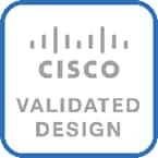
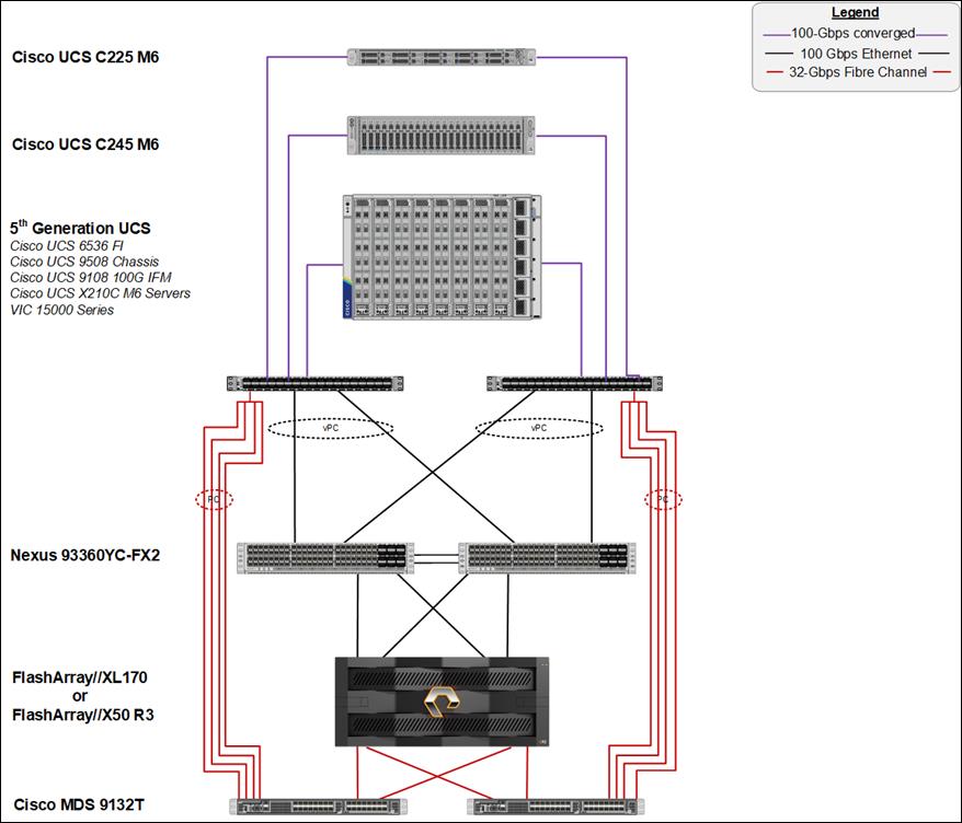
FlashStack architecture is built using the following infrastructure components for compute, network, and storage (Figure 1):
· Cisco Unified Computing System (Cisco UCS)
· Cisco Nexus 9000® switches
· Cisco MDS 9000 switches
· Pure Storage FlashArray
Figure 1. FlashStack Components
All the FlashStack components are integrated, so customers can deploy the solution quickly and economically while eliminating many of the risks associated with researching, designing, building, and deploying similar solutions from the foundation. One of the main benefits of FlashStack is its ability to maintain consistency at scale. Each of the component families shown in Figure 1 (Cisco UCS, Cisco Nexus, Cisco MDS, and Pure Storage FlashArray systems) offers platform and resource options to scale up or scale out the infrastructure while supporting the same features and functions.
This FlashStack solution with Cisco UCS X-Series and 5th Generation Fabric technology to enable end-to-end 100 Gigabit uses following hardware components:
· Cisco 5th Generation Cisco UCS 6536 Fabric Interconnects to support 10/25/40/100 Gigabit Ethernet connectivity from various components
· Each Cisco UCS X210c M6 compute node installed with 5th Generation Cisco VIC 15231
· Cisco UCS 9108 100G Intelligent Fabric Module to connect the I/O fabric between the 6536 Fabric Interconnect and the Cisco UCS X9508 Chassis
· Cisco UCS X9508 chassis with Cisco UCS X210c M6 compute nodes
· AMD CPU-based Cisco UCS C225 M6 and Cisco UCS C245 M6 Rack servers with Cisco UCS Virtual Interface Card 1495
· High-Speed Cisco NX-OS based Nexus 93360YC-FX2 switching design to support up to 100GbE connectivity.
· High-Speed Cisco NX-OS based MDS 9132T switching design to support up to 32Gb end-to-end connectivity to support SCSI and NVMe over Fibre Channel.
· Pure Storage FlashArray//XL170 and FlashArray//X50 R3 All Flash Storage with high-speed Ethernet or Fibre Channel connectivity
· Pure Storage FlashArray//XL170 and FlashArray//X50 R3 storage with 100 GbE connectivity to Cisco Nexus switching fabric and 32Gb FC connectivity to Cisco MDS switching fabric.
The software components consist of:
· Cisco Intersight platform to deploy, maintain, and support the FlashStack components
· Cisco Intersight Assist virtual appliance to help connect the Pure Storage FlashArray and VMware vCenter with the Cisco Intersight platform
· VMware vCenter 7.0 U3 to set up and manage the virtual infrastructure as well as integration of the virtual environment with Cisco Intersight software
5th Generation Cisco UCS Fabric Interconnects
The Cisco UCS Fabric Interconnects (FIs) provide a single point of connectivity and management for the entire Cisco UCS system. Typically deployed as an active/active pair, the system’s FIs integrate all components into a single, highly available management domain controlled by the Cisco UCS Manager or Cisco Intersight. Cisco UCS FIs provide a single unified fabric for the system, with low-latency, lossless, cut-through switching that supports LAN, SAN, and management traffic using a single set of cables.
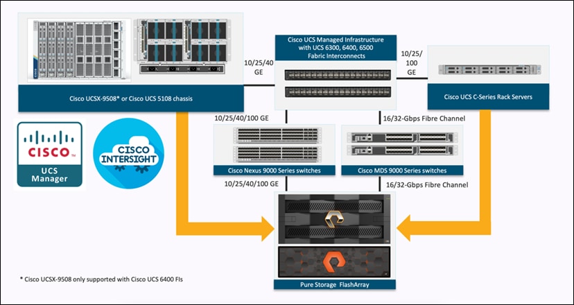
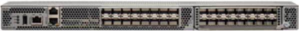
Figure 2. FI 6536 – Front and Rear view
The Cisco UCS 6536 Fabric Interconnect utilized in the current design is a One-Rack-Unit (1RU) 1/10/25/40/100 Gigabit Ethernet, FCoE, and Fibre Channel switch offering up to 7.42 Tbps throughput and up to 36 ports. The switch has 32 40/100-Gbps Ethernet ports and 4 unified ports that can support 40/100-Gbps Ethernet ports or 16 Fiber Channel ports after breakout at 8/16/32-Gbps FC speeds. The 16 FC ports after breakout can operate as an FC uplink or FC storage port. The switch also supports two ports at 1-Gbps speed using QSA, and all 36 ports can breakout for 10- or 25-Gbps Ethernet connectivity. All Ethernet ports can support FCoE.
The Cisco UCS 6536 Fabric Interconnect (FI) is a core part of the Cisco Unified Computing System, providing both network connectivity and management capabilities for the system (Figure 2). The Cisco UCS 6536 Fabric Interconnect offers line-rate, low-latency, lossless 10/25/40/100 Gigabit Ethernet, Fibre Channel, NVMe over Fabric, and Fibre Channel over Ethernet (FCoE) functions.
The Cisco UCS 6536 Fabric Interconnect provides the communication backbone and management connectivity for the Cisco UCS X-Series compute nodes, Cisco UCS X9508 X-series chassis, Cisco UCS B-series blade servers, Cisco UCS 5108 B-series server chassis, and Cisco UCS C-series rack servers. All servers attached to a Cisco UCS 6536 Fabric Interconnect become part of a single, highly available management domain. In addition, by supporting a unified fabric, Cisco UCS 6536 Fabric Interconnect provides both LAN and SAN connectivity for all servers within its domain.
From a networking perspective, the Cisco UCS 6536 uses a cut-through architecture, supporting deterministic, low-latency, line-rate 10/25/40/100 Gigabit Ethernet ports, a switching capacity of 7.42 Tbps per FI and 14.84 Tbps per unified fabric domain, independent of packet size and enabled services. It enables 1600Gbps bandwidth per X9508 chassis with X9108-IFM-100G in addition to enabling end-to-end 100G ethernet and 200G aggregate bandwidth per X210c compute node. With the X9108-IFM-25G and the IOM 2408, it enables 400Gbps bandwidth per chassis per FI domain. The product family supports Cisco low-latency, loss-less 10/25/40/100 Gigabit Ethernet unified network fabric capabilities, which increases the reliability, efficiency, and scalability of Ethernet networks. The 6536 Fabric Interconnect supports multiple traffic classes over a lossless Ethernet fabric from the server through the fabric interconnect. Significant TCO savings come from the Unified Fabric optimized server design in which network interface cards (NICs), Host Bus Adapters (HBAs), cables, and switches can be consolidated.
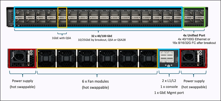
Cisco UCS Unified fabric: I/O consolidation
The Cisco UCS 6536 Fabric Interconnect is built to consolidate LAN and SAN traffic onto a single unified fabric, saving on Capital Expenditures (CapEx) and Operating Expenses (OpEx) associated with multiple parallel networks, different types of adapter cards, switching infrastructure, and cabling within racks. The unified ports allow ports in the fabric interconnect to support direct connections from Cisco UCS to existing native Fibre Channel SANs. The capability to connect to a native Fibre Channel protects existing storage-system investments while dramatically simplifying in-rack cabling.
Cisco UCS 6536 Fabric Interconnect supports I/O consolidation with end-to-end network virtualization, visibility, and QoS guarantees for the following LAN and SAN traffic:
· FC SAN, IP Storage (iSCSI, NFS), NVMeoF (NVMe/FC, NVMe/TCP, NVMe over ROCEv2)
· Server management and LAN traffic
Figure 3. Cisco UCS Unified Fabric
The I/O consolidation under the Cisco UCS 6536 fabric interconnect along with the stateless policy-driven architecture of Cisco UCS and the hardware acceleration of the Cisco UCS Virtual Interface card provides great simplicity, flexibility, resiliency, performance, and TCO savings for the customer’s compute infrastructure.
Cisco Unified Compute System X-Series
The Cisco UCS X-Series modular system is designed to take the current generation of the Cisco UCS platform to the next level with its design that will support future innovations and management in the cloud (Figure 4). Decoupling and moving platform management to the cloud allows the Cisco UCS platform to respond to features and scalability requirements much faster and more efficiently. Cisco UCS X-Series state-of-the-art hardware simplifies the datacenter design by providing flexible server options. A single server type that supports a broader range of workloads results in fewer different datacenter products to manage and maintain. The Cisco Intersight cloud management platform manages the Cisco UCS X-Series as well as integrates with third-party devices. These devices include VMware vCenter and Pure Storage to provide visibility, optimization, and orchestration from a single platform, thereby enhancing agility and deployment consistency.
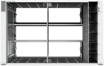
Figure 4. Cisco UCS X9508 Chassis
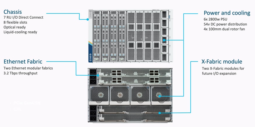
Cisco UCS X9508 Chassis
The Cisco UCS X-Series chassis is engineered to be adaptable and flexible. As shown in Figure 5, Cisco UCS X9508 chassis has only a power-distribution midplane. This innovative design provides fewer obstructions for better airflow. For I/O connectivity, vertically oriented compute nodes intersect with horizontally oriented fabric modules, allowing the chassis to support future fabric innovations. Cisco UCS X9508 Chassis’ superior packaging enables larger compute nodes, thereby providing more space for actual compute components, such as memory, GPU, drives, and accelerators. Improved airflow through the chassis enables support for higher power components, and more space allows for future thermal solutions (such as liquid cooling) without limitations.
Figure 5. Cisco UCS X9508 Chassis – Innovative Design
The Cisco UCS X9508 7-Rack-Unit (7RU) chassis has eight flexible slots. These slots can house a combination of compute nodes and a pool of future I/O resources that may include GPU accelerators, disk storage, and nonvolatile memory. At the top rear of the chassis are two Intelligent Fabric Modules (IFMs) that connect the chassis to upstream Cisco UCS 6500 Series Fabric Interconnects. At the bottom rear of the chassis are slots ready to house future X-Fabric modules that can flexibly connect the compute nodes with I/O devices. Six 2800W Power Supply Units (PSUs) provide 54V power to the chassis with N, N+1, and N+N redundancy. A higher voltage allows efficient power delivery with less copper and reduced power loss. Efficient, 100mm, dual counter-rotating fans deliver industry-leading airflow and power efficiency, and optimized thermal algorithms enable different cooling modes to best support the customer’s environment.
Cisco UCSX 9108-100G Intelligent Fabric Modules
The Cisco UCS 9108-100G and 9108-25G Intelligent Fabric Module (IFM) brings the unified fabric into the blade server enclosure, providing connectivity between the blade servers and the fabric interconnect, simplifying diagnostics, cabling, and management.
This FlashStack solution with Cisco UCS X-Series and 5th Generation Fabric technology uses Cisco UCS 9108 100G IFM.
Figure 6. Cisco UCS X9108-100G Intelligent Fabric Module
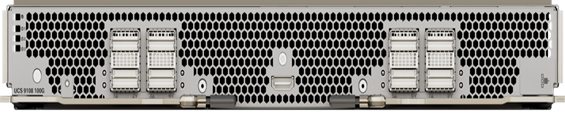
The Cisco UCS 9108 100G IFM connects the I/O fabric between the 6536 Fabric Interconnect and the Cisco UCS X9508 Chassis, enabling a lossless and deterministic converged fabric to connect all blades and chassis together. Because the fabric module is similar to a distributed line card, it does not perform any switching and is managed as an extension of the fabric interconnects. This approach removes switching from the chassis, reducing overall infrastructure complexity, and enabling Cisco UCS to scale to many chassis without multiplying the number of switches needed, reducing TCO, and allowing all chassis to be managed as a single, highly available management domain. The Cisco UCS 9108 100G IFM also manages the chassis environment (power supply, fans, and blades) in conjunction with the fabric interconnect. Therefore, separate chassis-management modules are not required.
The IFM plugs into the rear side of the Cisco UCS X9508 chassis. The IFM provides a data path from the chassis compute nodes to the Cisco UCS 6536 Fabric Interconnect. Up to two Intelligent Fabric Modules (IFMs) plug into the back of the Cisco UCS X9508 chassis.
The IFMs serve as line cards in the chassis and multiplex data from the compute nodes to the Fabric Interconnect (FI). They also monitor and manage chassis components such as fan units, power supplies, environmental data, LED status panel, and other chassis resources. The server compute node Keyboard-Video-Mouse (KVM) data, Serial over LAN (SoL) data, and Intelligent Platform Management Interface (IPMI) data also travel to the IFMs for monitoring and management purposes. In order to provide redundancy and failover, the IFMs are always used in pairs.
There are 8 x QSFP28 external connectors on an IFM to interface with a Cisco UCS 6536 Fabric Interconnect. The IFM internally provides 1 x 100G or 4 x 25G connections towards each UCS X210c Compute Node in Cisco X9508 chassis.
Cisco UCS X210c M6 Compute Node
The Cisco UCS X9508 Chassis is designed to host up to 8 Cisco UCS X210c M6 Compute Nodes. The hardware details of the Cisco UCS X210c M6 Compute Nodes are shown in Figure 7:
Figure 7. Cisco UCS X210c M6 Compute Node
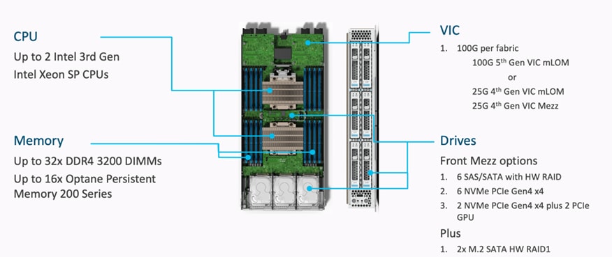
The Cisco UCS X210c M6 features:
· CPU: Up to 2x 3rd Gen Intel Xeon Scalable Processors with up to 40 cores per processor and 1.5 MB Level 3 cache per core
· Memory: Up to 32 x 256 GB DDR4-3200 DIMMs for a maximum of 8 TB of main memory.
· Disk storage: Up to 6 SAS or SATA drives can be configured with an internal RAID controller, or customers can configure up to 6 NVMe drives. 2 M.2 memory cards can be added to the Compute Node with RAID 1 mirroring.
· Virtual Interface Card (VIC): Up to 2 VICs including an mLOM Cisco VIC 15231 or 14425 and a mezzanine Cisco VIC card 14825 can be installed in a Compute Node.
· Security: The server supports an optional Trusted Platform Module (TPM). Additional security features include a secure boot FPGA and ACT2 anticounterfeit provisions.
Cisco UCS Virtual Interface Cards
Cisco UCS X210c M6 Compute Nodes supports firth generation Cisco UCS VIC 15231 along with fourth generation Cisco UCS VIC 14425 and Cisco UCS VIC 14825. This FlashStack solution with Cisco UCS X-Series and 5th Generation Fabric technology uses Cisco UCS VIC 15231 to enable end-to-ed 100 network connectivity.
Cisco UCS VIC 15231
Cisco UCS VIC 15231 fits the mLOM slot in the Cisco X210c Compute Node and enables up to 100 Gbps of unified fabric connectivity to each of the chassis IFMs for a total of 200 Gbps of connectivity per server.
Figure 8. Cisco VIC 15231 mLOM
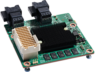
Cisco VIC 15231 connectivity to the IFM and up to the fabric interconnects is delivered through 2x 100-Gbps connections. Cisco VIC 15231 supports 256 virtual interfaces (both Fibre Channel and Ethernet) along with the latest networking innovations such as NVMeoF over RDMA (ROCEv2), VxLAN/NVGRE/GENEVE offload, and so on.
Figure 9. Single Cisco VIC 15231 in Cisco UCS X210c M6
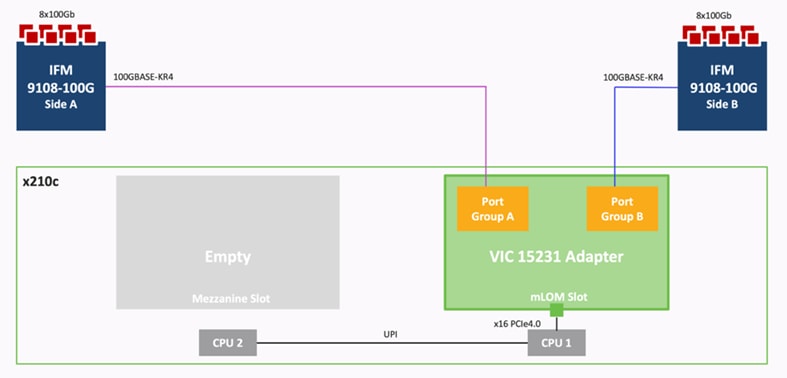
The connections between Cisco VIC 15231 and IFMs in Cisco UCS X-Series results in 2x better connectivity in Cisco UCS X210c M6 Compute Nodes compared to 4th generation Cisco VIC 14425 in the Cisco UCS x210 compute nodes.
Cisco VIC 14425
Cisco VIC 14425 fits the mLOM slot in the Cisco X210c Compute Node and enables up to 50 Gbps of unified fabric connectivity to each of the chassis IFMs for a total of 100 Gbps of connectivity per server. Cisco VIC 14425 connectivity to the IFM and up to the fabric interconnects is delivered through 4x 25-Gbps connections, which are configured automatically as 2x 50-Gbps port channels. Cisco VIC 14425 supports 256 virtual interfaces (both Fibre Channel and Ethernet) along with the latest networking innovations such as NVMeoF over RDMA (ROCEv2), VxLAN/NVGRE offload, and so on.
Figure 10. Single Cisco VIC 14425 in Cisco UCS X210c M6
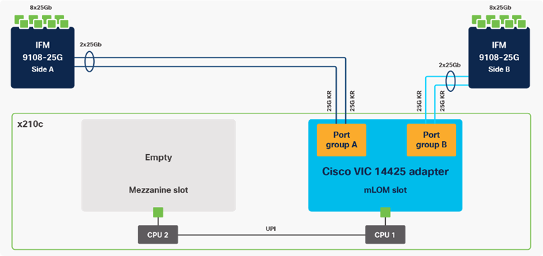
The connections between the 4th generation Cisco VIC (Cisco UCS VIC 1440) plus Port Expander in the Cisco UCS B200 blades and the I/O modules in the Cisco UCS 5108 chassis comprise of multiple 10Gbps KR lanes. The same connections between Cisco VIC 14425 and IFMs in Cisco UCS X-Series comprise of multiple 25Gbps KR lanes resulting in higher speed connectivity in Cisco UCS X210c M6 Compute Nodes.
Cisco VIC 14825
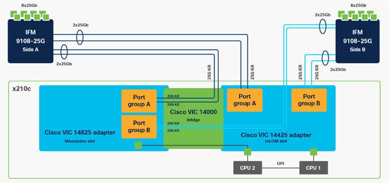
The optional Cisco VIC 14825 fits the mezzanine slot on the server. A bridge card (UCSX-V4-BRIDGE) extends this VIC’s 2x 50 Gbps of network connections up to the mLOM slot and out through the mLOM’s IFM connectors, bringing the total bandwidth to 100 Gbps per fabric for a total bandwidth of 200 Gbps per server.
Figure 11. Cisco VIC 14425 and 14825 in Cisco UCS X210c M6
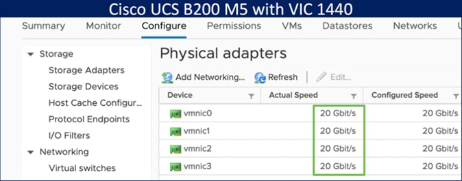
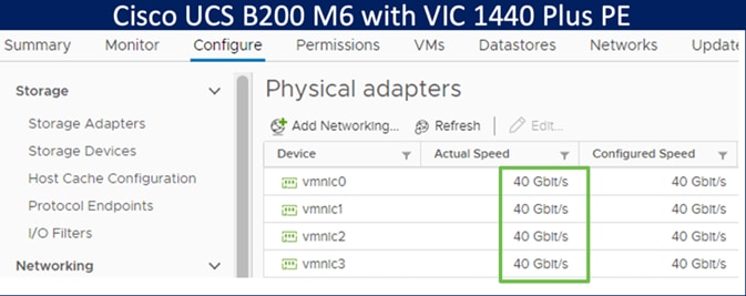
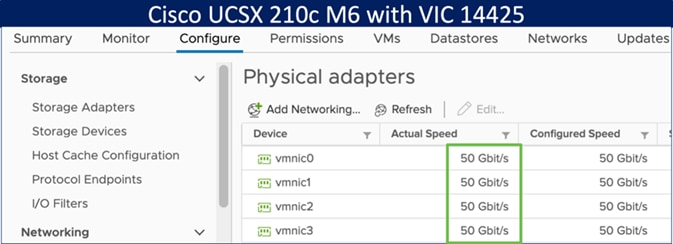
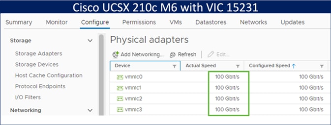
The network interface speed comparison between VMware ESXi installed on Cisco UCS B200 M5 with VIC 1440, Cisco UCS B200 M6 with VIC 1440 plus port expander, Cisco UCS X210c M6 with VIC 14425 and Cisco UCS X210c M6 with VIC 15231 are shown in Figure 12.
Figure 12. Network Interface Speed Comparison
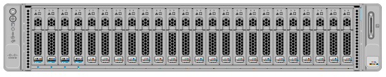
Cisco UCS C225 M6 and C245 M6 Rack Servers
The Cisco UCS C225 M6 and UCS C245 Rack Servers extend the capabilities of Cisco’s UCS portfolio with the addition of the AMD EPYC CPUs as well as 16 DIMM slots per CPU for 3200-MHz DDR4 DIMMs with individual DIMM capacity points up to 256 GB. The maximum memory capacity for 2 CPUs is 8 TB (for 32 x 256 GB DDR4 DIMMs1). The Cisco UCS C225M6 has a 1-Rack-Unit (RU) form factor while the Cisco UCS C245 has a 2-RU form factor and can hold more GPUs than the Cisco UCS C225. These servers can connect directly to the Cisco UCS 6536 Fabric Interconnects at 2x100Gbps with 4th Generation Cisco UCS VIC 1477 and 1495. These servers can also connect directly to the Cisco UCS 6536 Fabric Interconnects via 4x25G to 100G breakout cables with the 5th Generation VIC 15428 and 4th Generation VICs 1467 and 1455.
Figure 13. Cisco UCS C225 M6 Rack Server
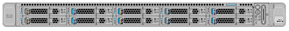
Figure 14. Cisco UCS C245 M6 Rack Server
The Cisco Intersight platform is a Software-as-a-Service (SaaS) infrastructure lifecycle management platform that delivers simplified configuration, deployment, maintenance, and support. The Cisco Intersight platform is designed to be modular, so customers can adopt services based on their individual requirements. The platform significantly simplifies IT operations by bridging applications with infrastructure, providing visibility and management from bare-metal servers and hypervisors to serverless applications, thereby reducing costs and mitigating risk. This unified SaaS platform uses a unified Open API design that natively integrates with third-party platforms and tools.
Figure 15. Cisco Intersight Overview
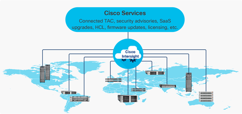
The main benefits of Cisco Intersight infrastructure services are as follows:
· Simplify daily operations by automating many daily manual tasks
· Combine the convenience of a SaaS platform with the capability to connect from anywhere and manage infrastructure through a browser or mobile app
· Stay ahead of problems and accelerate trouble resolution through advanced support capabilities
· Gain global visibility of infrastructure health and status along with advanced management and support capabilities
· Upgrade to add workload optimization and Kubernetes services when needed
Cisco Intersight Virtual Appliance and Private Virtual Appliance
In addition to the SaaS deployment model running on Intersight.com, on-premises options can be purchased separately. The Cisco Intersight Virtual Appliance and Cisco Intersight Private Virtual Appliance are available for organizations that have additional data locality or security requirements for managing systems. The Cisco Intersight Virtual Appliance delivers the management features of the Cisco Intersight platform in an easy-to-deploy VMware Open Virtualization Appliance (OVA) or Microsoft Hyper-V Server virtual machine that allows you to control the system details that leave your premises. The Cisco Intersight Private Virtual Appliance is provided in a form factor specifically designed for users who operate in disconnected (air gap) environments. The Private Virtual Appliance requires no connection to public networks or back to Cisco to operate.
Cisco Intersight Assist
Cisco Intersight Assist helps customers add endpoint devices to Cisco Intersight. A data center could have multiple devices that do not connect directly with Cisco Intersight. Any device that is supported by Cisco Intersight but does not connect to Intersight directly needs Cisco Intersight Assist to provide the necessary connectivity. In FlashStack, VMware vCenter and Pure Storage FlashArray connect to Intersight with the help of Intersight Assist appliance.
Cisco Intersight Assist is available within the Cisco Intersight Virtual Appliance, which is distributed as a deployable virtual machine contained within an Open Virtual Appliance (OVA) file format. More details about the Cisco Intersight Assist VM deployment configuration is covered in later sections.
Licensing Requirements
The Cisco Intersight platform uses a subscription-based license with multiple tiers. Customers can purchase a subscription duration of one, three, or five years and choose the required Cisco UCS server volume tier for the selected subscription duration. Each Cisco endpoint automatically includes a Cisco Intersight Base license at no additional cost when customers access the Cisco Intersight portal and claim a device. Customers can purchase any of the following higher-tier Cisco Intersight licenses using the Cisco ordering tool:
· Cisco Intersight Essentials: Essentials includes all the functions of the Base license plus additional features, including Cisco UCS Central Software and Cisco Integrated Management Controller (IMC) supervisor entitlement, policy-based configuration with server profiles, firmware management, and evaluation of compatibility with the Cisco Hardware Compatibility List (HCL).
· Cisco Intersight Advantage: Advantage offers all the features and functions of the Base and Essentials tiers. It includes storage widgets and cross-domain inventory correlation across compute, storage, and virtual environments (VMWare ESXi). It also includes OS installation for supported Cisco UCS platforms.
· Cisco Intersight Premier: In addition to all of the functions provided in the Advantage tier, Premier includes full subscription entitlement for Intersight Orchestrator, which provides orchestration across Cisco UCS and third-party systems.
Servers in the Cisco Intersight managed mode require at least the Essentials license. For more information about the features provided in the various licensing tiers, see https://intersight.com/help/getting_started#licensing_requirements.
Intersight Managed Mode
The Cisco UCS 6536 Fabric Interconnect is managed through Cisco Intersight. The Cisco UCS 6536 Fabric Interconnect supports Intersight Managed Mode, which enables full manageability of Cisco UCS elements behind the UCS 6536 FI through Cisco Intersight.
Connectivity for the Cisco UCS X9508 X-Series chassis is maintained through the Cisco UCS X9108-IFM-100G or X9108-IFM-25G Intelligent Fabric Module (IFM) in each X-series chassis. Connectivity for the Cisco UCS 5108 Blade Server Chassis is maintained through the Cisco UCS 2408 Series Fabric Extenders in each Cisco UCS 5108 blade chassis. The Cisco UCS C-Series servers can directly connect to Cisco UCS 6536 Fabric Interconnect through the Cisco UCS VIC 1400 series or the VIC 15000 series. The Cisco UCS C-Series servers can also connect to the FI 6536 using the Cisco Nexus 93360YC-FX2 in FEX-mode.
The Cisco UCS 6536 Fabric Interconnect supports out-of-band management through a dedicated 10/100/1000-Mbps Ethernet management port, as well as in-band management. The Cisco UCS 6536 Fabric Interconnect has L1/L2 ports for maintaining high availability within the UCS domain, one USB port for saving or loading configurations, and one console port for setting the initial configuration.
Note: To support the Cisco UCS X-Series, the fabric interconnects must be configured in Intersight Managed Mode (IMM). This option replaces the local management with Cisco Intersight cloud or appliance-based management.
The Cisco Nexus 9000 Series Switches offer both modular and fixed 1/10/25/40/100 Gigabit Ethernet switch configurations with scalability up to 60 Tbps of nonblocking performance with less than five-microsecond latency, wire speed VXLAN gateway, bridging, and routing support.
Figure 16. Cisco Nexus 93360YC-FX2 Switch
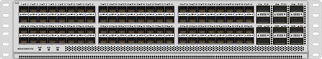
The Cisco Nexus 9000 series switch featured in this design is the Cisco Nexus 93360YC-FX2 configured in NX-OS standalone mode. NX-OS is a purpose-built datacenter operating system designed for performance, resiliency, scalability, manageability, and programmability at its foundation. It provides a robust and comprehensive feature set that meets the demanding requirements of virtualization and automation.
The Cisco Nexus 93360YC-FX2 Leaf Switch is a 2-Rack-Unit (2RU) Leaf switch that supports 7.2 Tbps of bandwidth and 2.4 bpps across 96 fixed 10/25G SFP+ ports and 12 fixed 40/100G QSFP28 ports. The 96 ports of downlinks support 1/10/25-Gbps. The 12 uplinks ports can be configured as 40- and 100-Gbps ports, offering flexible migration options. The switch has FC-FEC and RS-FEC enabled for 25Gbps support over longer distances.
Cisco MDS 9132T 32G Multilayer Fabric Switch
The Cisco MDS 9132T 32G Multilayer Fabric Switch is the next generation of the highly reliable, flexible, and low-cost Cisco MDS 9100 Series switches. It combines high performance with exceptional flexibility and cost effectiveness. This powerful, compact one Rack-Unit (1RU) switch scales from 8 to 32 line-rate 32 Gbps Fibre Channel ports.
Figure 17. Cisco MDS 9132T 32G Multilayer Fabric Switch
The Cisco MDS 9132T delivers advanced storage networking features and functions with ease of management and compatibility with the entire Cisco MDS 9000 family portfolio for reliable end-to-end connectivity. This switch also offers state-of-the-art SAN analytics and telemetry capabilities that have been built into this next-generation hardware platform. This new state-of-the-art technology couples the next-generation port ASIC with a fully dedicated network processing unit designed to complete analytics calculations in real time. The telemetry data extracted from the inspection of the frame headers are calculated on board (within the switch) and, using an industry-leading open format, can be streamed to any analytics-visualization platform. This switch also includes a dedicated 10/100/1000BASE-T telemetry port to maximize data delivery to any telemetry receiver, including Cisco Data Center Network Manager.
Cisco MDS 9148V 64G 48-Port Fibre Channel Switch
The next-generation Cisco MDS 9148V 64-Gbps 48-Port Fibre Channel Switch (Figure 18) supports 64, 32, and 16 Gbps Fibre Channel ports and provides high-speed Fibre Channel connectivity for all-flash arrays and high-performance hosts. This switch offers state-of-the-art analytics and telemetry capabilities built into its next-generation Application-Specific Integrated Circuit (ASIC) chipset. This switch allows seamless transition to Fibre Channel Non-Volatile Memory Express (NVMe/FC) workloads whenever available without any hardware upgrade in the SAN. It empowers small, midsize, and large enterprises that are rapidly deploying cloud-scale applications using extremely dense virtualized servers, providing the benefits of greater bandwidth, scale, and consolidation. This switch is now orderable from Cisco, is supported in FlashStack, but was not validated in this design.
Figure 18. Cisco MDS 9148V 64G 48-Port Fibre Channel Switch
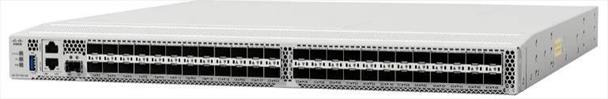
The Cisco MDS 9148V delivers advanced storage networking features and functions with ease of management and compatibility with the entire Cisco MDS 9000 family portfolio for reliable end-to-end connectivity. This switch also offers state-of-the-art SAN analytics and telemetry capabilities that have been built into this next-generation hardware platform. This new state-of-the-art technology couples the next-generation Cisco port ASIC with a fully dedicated network processing unit designed to complete analytics calculations in real time. The telemetry data extracted from the inspection of the frame headers are calculated on board (within the switch) and, using an industry-leading open format, can be streamed to any analytics-visualization platform. This switch also includes a dedicated 10/100/1000BASE-T telemetry port to maximize data delivery to any telemetry receiver, including Cisco Data Center Network Manager.
Cisco Data Center Network Manager (DCNM)-SAN
Cisco DCNM-SAN can be used to monitor, configure, and analyze Cisco 32Gbps Fibre Channel fabrics and show information about the Cisco Nexus switching fabric. Cisco DCNM-SAN is deployed as a virtual appliance from an OVA and is managed through a web browser. Once the Cisco MDS and Nexus switches are added with the appropriate credentials and licensing, monitoring of the SAN and Ethernet fabrics can begin. Additionally, VSANs, device aliases, zones, and zone sets can be added, modified, and deleted using the DCNM point-and-click interface. Device Manager can also be used to configure the Cisco MDS switches. SAN Analytics can be added to Cisco MDS switches to provide insights into the fabric by allowing customers to monitor, analyze, identify, and troubleshoot performance issues.
Note: Cisco DCNM-SAN is available as SAN Controller persona in Nexus Dashboard Fabric Controller (NDFC) and available exclusively on the Cisco Nexus Dashboard (ND) as an App. You can now enable the features you want at runtime (Fabric Controller (LAN), SAN Controller, and Fabric Discovery) which allows your clusters to scale better.
With the introduction of NDFC Release 12, users get a consistent experience across NDFC, and other services hosted on Nexus Dashboard including Insights and Orchestrator. As of publishing date of the document, Cisco DCNM 11.5(4) was used in the document as it was the suggested release. The future FlashStack design documents will use NDFC version 12 or higher.
Cisco DCNM Integration with Cisco Intersight
The Cisco Network Insights Base (Cisco NI Base) application provides several TAC assist functionalities which are useful when working with Cisco TAC. Cisco NI base provides a way for Cisco customers to collect technical support information across multiple devices and upload them to Cisco Cloud. The Cisco NI Base app collects the CPU, device name, device product id, serial number, version, memory, device type, and disk usage information for the nodes in the fabric. Cisco NI Base application is connected to the Cisco Intersight cloud portal through a device connector which is embedded in the management controller of the Cisco DCNM platform. The device connector provides a safe way for connected Cisco DCNM to send and receive information from the Cisco Intersight portal, using a secure Internet connection.
The Pure Storage FlashArray Family delivers software-defined all-flash power and reliability for businesses of every size. FlashArray is all-flash enterprise storage that is up to 10X faster, space and power efficient, reliable, and far simpler than other available solutions. Compared to traditional performance disk arrays, FlashArray costs less with total cost of ownership (TCO) savings of up to 50%. At the top of the FlashArray line is the new FlashArray//XL; this new platform is designed for today’s higher-powered multicore CPUs, allowing //XL to increase performance even over our FlashArray//X models, with more power to take apps to the next level. //XL represents next-level scale and performance for high-demand enterprise applications. The //XL platform enhancements give higher performance, higher capacity density per RU, and higher scale with better resiliency. By being engineered for next-gen CPU and flash technologies to future-proof your investment, you can achieve workload consolidation with room to grow in place, with less frequent servicing by IT staff.
Purity for FlashArray (Purity//FA 6)
Every FlashArray is driven by Purity Operating Environment software. Purity//FA6 implements advanced data reduction, storage management, and flash management features, enabling customers to enjoy tier 1 data services for all workloads. Purity software provides proven 99.9999 percent availability over 2 years, completely nondisruptive operations, 2X better data reduction, and the power and efficiency of DirectFlashTM. Purity also includes enterprise-grade data security, comprehensive data-protection options, and complete business continuity with an ActiveCluster multi-site stretch cluster. All these features are included with every Pure Storage array.
Figure 19. Pure Storage FlashArray//XL
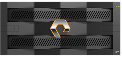
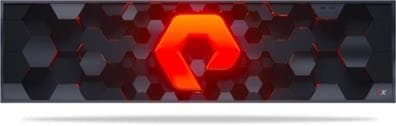
Figure 20. Pure Storage FlashArray//X
FlashArray//XL Specification
Table 1 lists both the capacity and physical aspects of various FlashArray systems.
Table 1. FlashArray//X R3 and //XL Specifications
|
|
Capacity |
Physical |
| //XL130 |
Up to 3.53 PB/3.3 PiB effective capacity** Up to 968 TB/880 TiB raw capacity† |
5RU; 1550–2000 watts (nominal – peak) 167.0lb. (75.7kg) fully loaded; 8.72 x 18.94 x 29.72 in. |
| //XL170 |
Up to 5.5 PB/5.13 PiB effective capacity** Up to 1.4 PB/1.31 PiB raw capacity† |
5RU; 1850–2355 watts (nominal – peak) 167.0lb. (75.7kg) fully loaded; 8.72 x 18.94 x 29.72 in. |
| DirectFlash Shelf |
Up to 1.9 PB effective capacity Up to 512 TB / 448.2 TiB raw capacity |
3U; 460–500 watts (nominal–peak) 87.7 lbs. (39.8 kg) fully loaded; 5.12” x 18.94” x 29.72” |
** Effective capacity assumes high availability, RAID, and metadata overhead, GB-to-GiB conversion, and includes the benefit of data reduction with always-on inline deduplication, compression, and pattern removal. Average data reduction is calculated at 5-to-1 and does not include thin provisioning.
† Array accepts Pure Storage DirectFlash Shelf and/or Pure.
Table 2 lists the various connectivity options using both onboard and host I/O cards.
Table 2. FlashArray //XL Connectivity
| Chassis |
Onboard ports (per controller) |
Host I/O cards (3 slots/controller) |
| //XL |
Two 1-/10-/25-GE iSCSI/Roc |
2-port 10-/25 or 100-Gb NVMe/RoCE |
| //XL |
Four 10/25-GE replication |
2-port 32-/64-Gb Fibre Channel (NVMe-oF Ready) |
| //XL |
Two 1-Gb management ports |
4-port 32-/64-Gb Fibre Channel (NVMe-oF Ready) |
FlashArray//X R3 Specification
Table 3 lists both the capacity and physical aspects of various FlashArray systems.
Table 3. FlashArray//X R3 and //XL Specifications
|
|
Capacity |
Physical |
| //X10 |
Up to 73 TB/66.2 TiB (tebibyte) effective capacity** Up to 22 TB/19.2 TiB raw capacity |
3RU; 640–845 watts (nominal – peak) 95 lb. (43.1 kg) fully loaded; 5.12 x 18.94 x 29.72 in. |
| //X20 |
Up to 314 TB/285.4 TiB (tebibyte) effective capacity** Up to 94 TB/88 TiB raw capacity† |
3RU; 741–973 watts (nominal – peak) 95 lb. (43.1 kg) fully loaded; 5.12 x 18.94 x 29.72 in. |
| //X50 |
Up to 663 TB/602.9 TiB effective capacity** Up to 185 TB/171 TiB raw capacity† |
3RU; 868–1114 watts (nominal – peak) 95 lb. (43.1 kg) fully loaded; 5.12 x 18.94 x 29.72 in. |
| //X70 |
Up to 2286 TB/2078.9 TiB effective capacity** Up to 622 TB/544.2 TiB raw capacity† |
3RU; 1084–1344 watts (nominal – peak) 97 lb. (44.0 kg) fully loaded; 5.12 x 18.94 x 29.72 in. |
| //X90 |
Up to 3.3 PB/3003.1 TiB effective capacity** Up to 878 TB/768.3 TiB raw capacity† |
3–6RU; 1160–1446 watts (nominal – peak) 97 lb. (44 kg) fully loaded; 5.12 x 18.94 x 29.72 in. |
| DirectFlash Shelf |
Up to 1.9 PB effective capacity** Up to 512 TB/448.2 TiB raw capacity |
3RU; 460–500 watts (nominal – peak) 87.7 lb. (39.8kg) fully loaded; 5.12 x 18.94 x 29.72 in. |
** Effective capacity assumes high availability, RAID, and metadata overhead, GB-to-GiB conversion, and includes the benefit of data reduction with always-on inline deduplication, compression, and pattern removal. Average data reduction is calculated at 5-to-1 and does not include thin provisioning.
† Array accepts Pure Storage DirectFlash Shelf and/or Pure.
Table 4 lists the various connectivity options using both onboard and host I/O cards.
Table 4. FlashArray //X Connectivity
| Chassis |
Onboard ports (per controller) |
Host I/O cards (3 slots/controller) |
|
| //X |
Two 1-/10-/25-GE |
2-port 10GBASE-T Ethernet |
2-port 25-/50 or 100-Gb NVMe/RoCE |
| //X |
Two 1-/10-/25-GE replication |
2-port 1/10/25 GE |
2-port 16-/32-Gb Fibre Channel (NVMe-oF Ready) |
| //X |
Two 1-Gb management ports |
2-port 40 GE |
4-port 16-/32-Gb Fibre Channel (NVMe-oF Ready) |
Pure1
Pure1, a cloud-based management, analytics, and support platform, expands the self-managing, plug-n-play design of Pure all-flash arrays with the machine learning predictive analytics and continuous scanning of Pure1 Meta™ to enable an effortless, worry-free data platform.
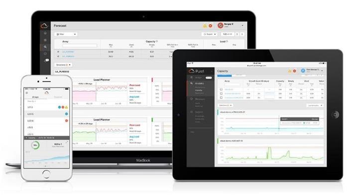
Pure1 Manage
Pure1 Manage is a SaaS-based offering that allows customers to manage their array from any browser or from the Pure1 Mobile App with nothing extra to purchase, deploy, or maintain. From a single dashboard, customers can manage all their arrays and have full storage health and performance visibility.
Pure1 Analyze
Pure1 Analyze delivers true performance forecasting, giving customers complete visibility into the performance and capacity needs of their arrays, now and in the future. Performance forecasting enables intelligent consolidation and workload optimization.
Pure1 Support
Pure Storage support team with the predictive intelligence of Pure1 Meta delivers unrivaled support that’s a key component in FlashArray 99.9999% availability. Some of the customer issues are identified and fixed without any customer intervention.
Pure1 META
The foundation of Pure1 services, Pure1 Meta is global intelligence built from a massive collection of storage array health and performance data. By continuously scanning call-home telemetry from Pure’s installed base, Pure1 Meta uses machine learning predictive analytics to help resolve potential issues, optimize workloads, and provide accurate forecasting. Meta is always expanding and refining what it knows about array performance and health.
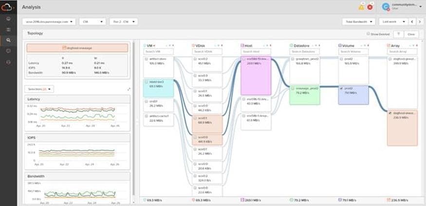
Pure1 VM Analytics
Pure1 helps you narrow down the troubleshooting steps in your virtualized environment. VM Analytics provides you with a visual representation of the IO path from the VM all the way through to the FlashArray. Other tools and features guide you through identifying where an issue might be occurring in order to help eliminate potential candidates for a problem.
VM Analytics doesn’t only help when there’s a problem. The visualization allows you to identify which volumes and arrays particular applications are running on. This brings the whole environment into a more manageable domain.
VMware vSphere is a virtualization platform for holistically managing large collections of infrastructures (resources including CPUs, storage, and networking) as a seamless, versatile, and dynamic operating environment. Unlike traditional operating systems that manage an individual machine, VMware vSphere aggregates the infrastructure of an entire data center to create a single powerhouse with resources that can be allocated quickly and dynamically to any application in need.
VMware vSphere 7.0 U3 has several improvements and simplifications including, but not limited to:
· vSphere Memory Monitoring and Remediation, and support for snapshots of PMem VMs: vSphere Memory Monitoring and Remediation collects data and provides visibility of performance statistics to help you determine if your application workload is regressed due to Memory Mode. vSphere 7.0 Update 3 also adds support for snapshots of PMem VMs.
· Improved interoperability between vCenter Server and ESXi versions: Starting with vSphere 7.0 Update 3, vCenter Server can manage ESXi hosts from the previous two major releases and any ESXi host from version 7.0 and 7.0 updates. For example, vCenter Server 7.0 Update 3 can manage ESXi hosts of versions 6.5, 6.7 and 7.0, all 7.0 update releases, including later than Update 3, and a mixture of hosts between major and update versions.
· New VMNIC tag for NVMe-over-RDMA (NVME/RoCEv2) storage traffic: ESXi 7.0 Update 3 adds a new VMNIC tag for NVMe-over-RDMA (NVMe/RoCEv2) storage traffic. This VMkernel port setting enables NVMe-over-RDMA traffic to be routed over the tagged interface. You can also use the ESXCLI command esxcli network ip interface tag add -i <interface name> -t NVMeRDMA to enable the NVMeRDMA VMNIC tag.
· NVMe over TCP support: vSphere 7.0 Update 3 extends the NVMe-oF suite with the NVMe over TCP storage protocol to enable high performance and parallelism of NVMe devices over a wide deployment of TCP/IP networks.
· Micro-second level time accuracy for workloads: ESXi 7.0 Update 3 adds the hardware timestamp Precision Time Protocol (PTP) to enable micro-second level time accuracy. For more information, see Use PTP for Time and Date Synchronization of a Host.
For more information about VMware vSphere and its components, see: https://www.vmware.com/products/vsphere.html.
VMware vSphere vCenter
VMware vCenter Server provides unified management of all hosts and VMs from a single console and aggregates performance monitoring of clusters, hosts, and VMs. VMware vCenter Server gives administrators a deep insight into the status and configuration of compute clusters, hosts, VMs, storage, the guest OS, and other critical components of a virtual infrastructure. VMware vCenter manages the rich set of features available in a VMware vSphere environment.
Ansible is simple and powerful, allowing users to easily manage various physical devices within FlashStack including the provisioning of Cisco UCS servers, Cisco Nexus switches, Pure FlashArray storage and VMware vSphere. Using Ansible’s Playbook-based automation is easy and integrates into your current provisioning infrastructure. This solution offers Ansible Playbooks that are made available from a GitHub repository that customers can access to automate the FlashStack deployment.
GitHub repository is available here: https://github.com/ucs-compute-solutions/FlashStack_IMM_Ansible
Cisco Intersight Assist Device Connector for VMware vCenter and Pure Storage FlashArray
Cisco Intersight integrates with VMware vCenter and Pure Storage FlashArray as follows:
· Cisco Intersight uses the device connector running within Cisco Intersight Assist virtual appliance to communicate with the VMware vCenter.
· Cisco Intersight uses the device connector running within a Cisco Intersight Assist virtual appliance to integrate with all Pure Storage FlashArray /models. The newest version 1.1 of Pure Storage integration to Cisco Intersight introduces support for REST API 2.x for FlashArray products (running Purity//FA 6.0.3 or later), along with User Agent support (for telemetry). Intersight Cloud Orchestrator now has new storage tasks for adding/removing a Pure Storage snapshot and copy a Pure Storage volume from snapshot.
Figure 21. Cisco Intersight and vCenter and Pure Storage Integration
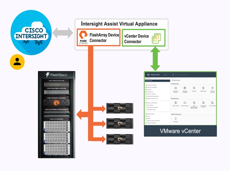
The device connector provides a safe way for connected targets to send information and receive control instructions from the Cisco Intersight portal using a secure Internet connection. The integration brings the full value and simplicity of Cisco Intersight infrastructure management service to VMware hypervisor and FlashArray storage environments. The integration architecture enables FlashStack customers to use new management capabilities with no compromise in their existing VMware or FlashArray operations. IT users will be able to manage heterogeneous infrastructure from a centralized Cisco Intersight portal. At the same time, the IT staff can continue to use VMware vCenter and the Pure Storage dashboard for comprehensive analysis, diagnostics, and reporting of virtual and storage environments. The next section addresses the functions that this integration provides.
This chapter contains the following:
· Cisco Nexus Ethernet Connectivity
· Cisco MDS SAN Connectivity - Fibre Channel Design Only
· Cisco UCS X-Series Configuration - Cisco Intersight Managed Mode
· Pure Storage FlashArray – Storage Design
· VMware vSphere – ESXi Design
· Cisco Intersight Integration with FlashStack
The FlashStack VSI with 5th Generation Fabric Technology and Cisco UCS X-Series enables end-to-end 100 Gigabit Ethernet and 32 Gigabit Fibre channel connectivity. The solution delivers a cloud-managed infrastructure solution on the latest Cisco UCS hardware. VMware vSphere 7.0 U3 hypervisor is installed on the Cisco UCS X210c, and C-Series M6 Compute Nodes configured for stateless compute design using boot from SAN. Pure Storage FlashArray//XL 170 and FlashArray//X50 R3 provides the storage infrastructure required for setting up the VMware environment. The Cisco Intersight cloud-management platform is utilized to configure and manage the infrastructure. The solution requirements and design details are explained in this section.
The FlashStack VSI with Cisco UCS X-Series and 5th Generation Fabric Technology meets the following general design requirements:
· Resilient design across all layers of the infrastructure with no single point of failure
· Scalable design with the flexibility to add compute and storage capacity or network bandwidth as needed
· Modular design that can be replicated to expand and grow as the needs of the business grow
· Flexible design that can support different models of various components with ease
· Simplified design with ability to integrate and automate with external automation tools
· Cloud-enabled design which can be configured, managed, and orchestrated from the cloud using GUI or APIs
FlashStack with 5th Generation fabric technology and Cisco UCS X-Series supports both IP-based and Fibre Channel based storage access design. For the IP-based solution, iSCSI configuration on Cisco UCS and Pure Storage FlashArray is utilized to set up storage access including boot from SAN configuration for the compute nodes. For the Fibre Channel designs, Pure Storage FlashArray and Cisco UCS X-Series are connected using Cisco MDS 9132T switches and storage access, including boot from SAN, is provided over the Fibre Channel network. The physical connectivity details for both IP and FC designs are explained below.
IP-based Storage Access
The physical topology for the IP-based FlashStack is shown in Figure 22.
Figure 22. FlashStack - Physical Topology for IP Connectivity
To validate the IP-based storage access in a FlashStack configuration, the components are set up as follows:
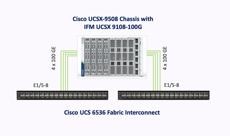
· Cisco UCS 6536 Fabric Interconnects provide the chassis and network connectivity.
· The Cisco UCS X9508 Chassis connects to fabric interconnects using Cisco UCSX 9108-100G intelligent fabric modules (IFMs), where four 100 Gigabit Ethernet ports are used on each IFM to connect to the appropriate FI. If additional bandwidth is required, all eight 100 Gigabit ports can be utilized.
· Cisco UCSX-210c M6 Compute Nodes contain 5th Generation Cisco 15231 virtual interface cards.
· AMD based Cisco UCS C225 M6 Rack Servers with Cisco VIC 1495
· AMD based Cisco UCS C245 M6 Rack Servers with Cisco VIC 1495
· Cisco Nexus 93360YC-FX2 Switches in Cisco NX-OS mode provide the switching fabric.
· Cisco UCS 6536 Fabric Interconnect 100-Gigabit Ethernet uplink ports connect to Cisco Nexus 93360YC-FX2 Switches in a Virtual Port Channel (vPC) configuration.
· The Pure Storage FlashArray//XL170 and FlashArray//X50 R3 connects to the Cisco Nexus 93360YC-FX2 switches using four 100-GE ports.
· VMware 7.0 U3 ESXi software is installed on Cisco UCSX-210c M6 Compute Nodes to validate the infrastructure.
FC-based Storage Access
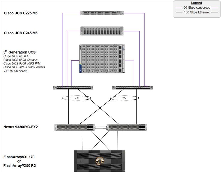
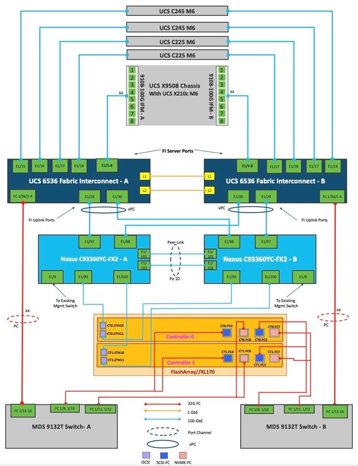
The physical topology for the FlashStack for FC connectivity is shown in Figure 23.
Figure 23. FlashStack - Physical Topology for FC Connectivity
To validate the FC-based storage access in a FlashStack configuration, the components are set up as follows:
· Cisco UCS 6536 Fabric Interconnects provide the chassis and network connectivity.
· The Cisco UCS X9508 Chassis connects to fabric interconnects using Cisco UCSX 9108-100G Intelligent Fabric Modules (IFMs), where four 100 Gigabit Ethernet ports are used on each IFM to connect to the appropriate FI.
· Cisco UCS X210c M6 Compute Nodes contain fifth-generation Cisco UCS 15231 virtual interface cards.
· AMD based Cisco UCS C225 M6 Rack Servers with Cisco VIC 1495.
· AMD based Cisco UCS C245 M6 Rack Servers with Cisco VIC 1495.
· Cisco Nexus switches in Cisco NX-OS mode provide the switching fabric.
· Cisco UCS 6536 Fabric Interconnect 100 Gigabit Ethernet uplink ports connect to Cisco Nexus 93360YC-FX2 Switches in a vPC configuration.
· The Cisco 128G FC QSPF (PID: DS-SFP-4x32G-SW) and multi-mode OM4, 8 fiber MPO to LC breakout cable are used to connect between Cisco UCS 6536 Fabric Interconnects at 128G and Cisco MDS 9132T at 32G speeds.
· 128 to 32-Gbps breakout Fibre Channel connections configured as a single port channel for SAN connectivity.
· The Pure Storage FlashArray//XL170 and FlashArray//X50 R3 connects to the Cisco MDS 9132T switches using 32-Gbps Fibre Channel connections for SAN connectivity.
· VMware 7.0 U3 ESXi software is installed on Cisco UCS X210c M6 Compute Nodes to validate the infrastructure.
The information in this section is provided as a reference for cabling the physical equipment in a FlashStack environment. To simplify cabling requirements, a cabling diagram was used. Figure 24 details the cable connections used in the validation lab for FlashStack topology based on the Cisco UCS 6536 fabric interconnect.
This document assumes that out-of-band management ports are plugged into an existing management infrastructure at the deployment site. These interfaces will be used in various configuration steps.
Cisco 128G FC QSPF (PID: DS-SFP-4x32G-SW) is used to connect between Cisco UCS 6536 Fabric Interconnects at 128G and Cisco MDS 9132T at 32G speeds using a multi-mode OM4, 8 fiber MPO to LC breakout cable. 128 to 32-Gbps breakout Fibre Channel connections configured as a single port channel for SAN connectivity.
A total of eight 32Gb links connect the MDS switches to the Pure FlashArray//XL170 and FlashArray//X50 R3 controllers, four of these have been used for scsi-fc and the other four to support nvme-fc.
The 100Gb links connect the Cisco UCS Fabric Interconnects to the Cisco Nexus Switches with vPC configured. Also, Pure FlashArray//XL170 and FlashArray//X50 R3 controllers are connected to the Cisco Nexus Switches for iSCSI connectivity.
Additional 1Gb management connections will be needed for an out-of-band network switch that sits apart from the FlashStack infrastructure. Each Cisco UCS fabric interconnect and Cisco Nexus switch is connected to the out-of-band network switch, and each FlashArray controller has a connection to the out-of-band network switch. Layer 3 network connectivity is required between the Out-of-Band (OOB) and In-Band (IB) Management Subnets.
Figure 24. FlashStack Cabling with Cisco UCS 6536 Fabric Interconnect
Note: Make sure to use the cabling directions in this section as a guide.
Note: A single Cisco 128G FC QSPF is used to connect between Cisco UCS 6536 Fabric Interconnects and Cisco MDS 9132T. Multiple such connectors can be used based on requirement.
Note: Cisco UCS 5108 chassis with Cisco UCS B200 M6 servers can also be connected to the same set of fabric interconnects with common management using Cisco Intersight.
Note: Connectivity is shown only for Pure FlashArray//XL170 for simplicity.
VLAN Configuration
Table 5 lists the VLANs configured for setting up the FlashStack environment along with their usage.
| VLAN ID |
Name |
Usage |
| 3 |
Native-VLAN |
Use VLAN 3 as native VLAN instead of default VLAN (1). |
| 1030 |
OOB-MGMT-VLAN |
Out-of-band management VLAN to connect management ports for various devices |
| 1031 |
IB-MGMT-VLAN |
In-band management VLAN utilized for all in-band management connectivity, for example, ESXi hosts, VM management, and so on. |
| 1032 |
VM-Traffic |
VM data traffic VLAN |
| 3119* |
iSCSI-A |
iSCSI-A path for storage traffic including boot-from-san traffic |
| 3219* |
iSCSI-B |
iSCSI-B path for storage traffic including boot-from-san traffic |
| 3319 |
vMotion |
VMware vMotion traffic |
* iSCSI VLANs are not required if using FC storage connectivity.
Some of the key highlights of VLAN usage are as follows:
· VLAN 1030 allows customers to manage and access out-of-band management interfaces of various devices.
· VLAN 1031 is used for in-band management of VMs, ESXi hosts, and other infrastructure services
· A pair of iSCSI VLANs (3119 and 3219) is configured to provide storage access including access to boot LUNs for ESXi hosts. These VLANs are not needed when configuring Fibre Channel connectivity.
· VLAN 3319 is used for VM vMotion
In FlashStack deployments, each Cisco UCS server equipped with a Cisco Virtual Interface Card (VIC) is configured for multiple virtual Network Interfaces (vNICs), which appear as standards-compliant PCIe endpoints to the OS. The end-to-end logical connectivity including VLAN/VSAN usage between the server profile for an ESXi host and the storage configuration on Pure Storage FlashArray is described below.
Logical Topology for IP-based Storage Access
Figure 25 illustrates the end-to-end connectivity design for IP-based storage access.
Figure 25. Logical End-to-End Connectivity for iSCSI Design
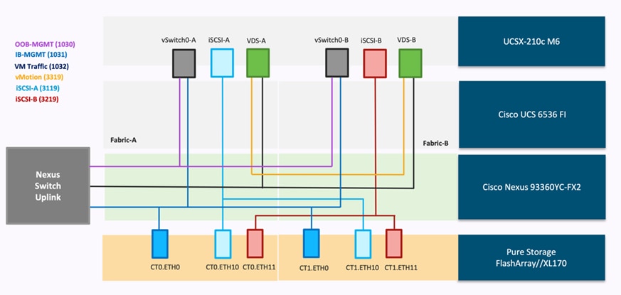
Each ESXi server profile supports:
· Managing the ESXi hosts using a common management segment
· Diskless SAN boot using iSCSI with persistent operating system installation for true stateless computing
· Six vNICs where:
° Two redundant vNICs (vSwitch0-A and vSwitch0-B) carry management traffic. The maximum transmission unit (MTU) value for these vNICs is set as a Jumbo MTU (9000).
° The vSphere distributed switch uses two redundant vNICs (VDS-A and VDS-B) to carry VMware vMotion traffic and customer application data traffic. The MTU for the vNICs is set to Jumbo MTU (9000).
° The iSCSI-A vSwitch uses one iSCSI-A vNIC to provide access to the iSCSI-A path. The MTU value for the vNIC is set to Jumbo MTU (9000).
° The iSCSI-B vSwitch uses one iSCSI-B vNIC to provide access to the iSCSI-B path. The MTU value for this vNIC is set to Jumbo MTU (9000).
· Each ESXi host (compute node) accesses datastores from Pure Storage FlashArray using iSCSI to deploy virtual machines.
Logical Topology for FC-based Storage Access
Figure 26 illustrates the end-to-end connectivity design for FC-based storage access.
Figure 26. Logical End-to-End Connectivity for FC Design
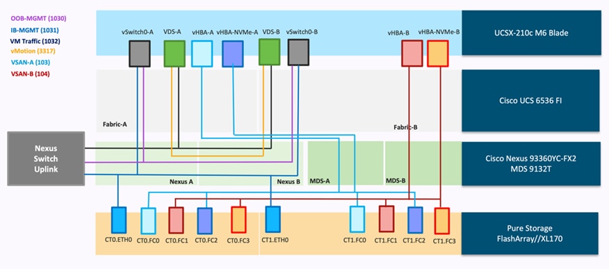
Each ESXi server profile supports:
· Managing the ESXi hosts using a common management segment
· Diskless SAN boot using FC with persistent operating system installation for true stateless computing
· Four vNICs where:
° Two redundant vNICs (vSwitch0-A and vSwitch0-B) carry management traffic. The MTU value for these vNICs is set as a Jumbo MTU (9000).
° The vSphere Distributed switch uses two redundant vNICs (VDS-A and VDS-B) to carry VMware vMotion traffic and customer application data traffic. The MTU for the vNICs is set to Jumbo MTU (9000).
· Four vHBAs where:
° One vHBA (vHBA-A) defined on Fabric A provides access to the SAN-A path (FC Initiator)
° One vHBA (vHBA-B) defined on Fabric B provides access to the SAN-B path (FC Initiator)
° One vHBA (vHBA-NVMe-A) defined on Fabric A provides access to the SAN-A path for NVMe over Fabric traffic (FC-NVMe Initiator)
° One vHBA (vHBA-NVMe-B) defined on Fabric B provides access to the SAN-B path for NVMe over Fabric traffic (FC-NVMe Initiator)
° Each ESXi host (compute node) accesses datastores from Pure Storage FlashArray using Fibre Channel to deploy virtual machines.
The Cisco UCS X9508 Chassis is equipped with the Cisco UCSX 9108-100G intelligent fabric modules (IFMs). The Cisco UCS X9508 Chassis connects to each Cisco UCS 6536 FI using four 100GE ports, as shown in Figure 27. If the customers require more bandwidth, all eight ports on the IFMs can be connected to each FI.
Figure 27. Cisco UCS X9508 Chassis Connectivity to Cisco UCS Fabric Interconnects
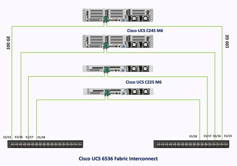
Cisco UCS C-Series servers are connected to each Cisco UCS 6536 FI using a 100GE ports as shown in the figure below:
Cisco Nexus Ethernet Connectivity
The Cisco Nexus 93360YC-FX2 device configuration suffices the core networking requirements for Layer 2 and Layer 3 communication. Some of the key NX-OS features implemented within the design are:
· Feature interface-vlan – Allows for VLAN IP interfaces to be configured within the switch as gateways.
· Feature HSRP – Allows for Hot Standby Routing Protocol configuration for high availability.
· Feature LACP – Allows for the utilization of Link Aggregation Control Protocol (802.3ad) by the port channels configured on the switch.
· Feature vPC – Virtual Port-Channel (vPC) presents the two Nexus switches as a single “logical” port channel to the connecting upstream or downstream device.
· Feature LLDP - Link Layer Discovery Protocol (LLDP), a vendor-neutral device discovery protocol, allows the discovery of both Cisco devices and devices from other sources.
· Feature NX-API – NX-API improves the accessibility of CLI by making it available outside of the switch by using HTTP/HTTPS. This feature helps with configuring the Cisco Nexus switch remotely using the automation framework.
· Feature UDLD – Enables unidirectional link detection for various interfaces.
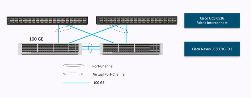
Cisco UCS Fabric Interconnect 6536 Ethernet Connectivity
Cisco UCS 6536 FIs are connected to Cisco Nexus 93360YC-FX2 switches using 100GE connections configured as virtual port channels. Each FI is connected to both Cisco Nexus switches using a 100G connection; additional links can easily be added to the port channel to increase the bandwidth as needed. Figure 28 illustrates the physical connectivity details.
Figure 28. Cisco UCS 6536 FI Ethernet Connectivity
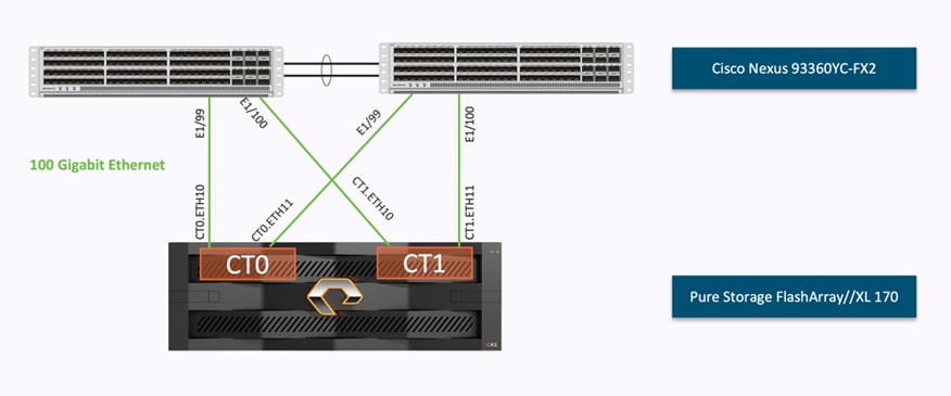
Pure Storage FlashArray//XL170 Ethernet Connectivity
Pure Storage FlashArray controllers are connected to Cisco Nexus Cisco Nexus 93360YC-FX2 switches using redundant 100-GE. Figure 29 illustrates the physical connectivity details.
Figure 29. Pure Storage FlashArray//XL170 Ethernet Connectivity
Cisco MDS SAN Connectivity – Fibre Channel Design Only
The Cisco MDS 9132T is the key design component bringing together the 32Gbps Fibre Channel (FC) capabilities to the FlashStack design. A redundant 32 Gbps Fibre Channel SAN configuration is deployed utilizing two MDS 9132Ts switches. Some of the key MDS features implemented within the design are:
· Feature NPIV: N port identifier virtualization (NPIV) provides a means to assign multiple FC IDs to a single N port.
· Feature fport-channel-trunk: F-port-channel-trunks allow for the fabric logins from the NPV switch to be virtualized over the port channel. This provides nondisruptive redundancy should individual member links fail.
· Smart-Zoning: a feature that reduces the number of TCAM entries by identifying the initiators and targets in the environment.
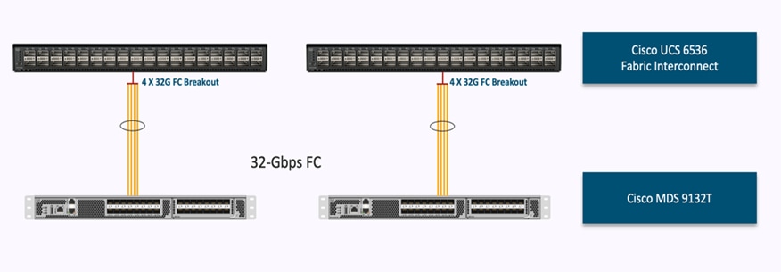
Cisco UCS Fabric Interconnect 6536 SAN Connectivity
For SAN connectivity, each Cisco UCS 6536 Fabric Interconnect is connected to a Cisco MDS 9132T SAN switch using 4 x 32G Fibre Channel breakout connection, as shown in Figure 30. Fiber channel connectivity will be provided using 128Gig FC QSFP and multimode MPO to LC breakout cable.
Figure 30. Cisco UCS 6536 FI SAN Connectivity
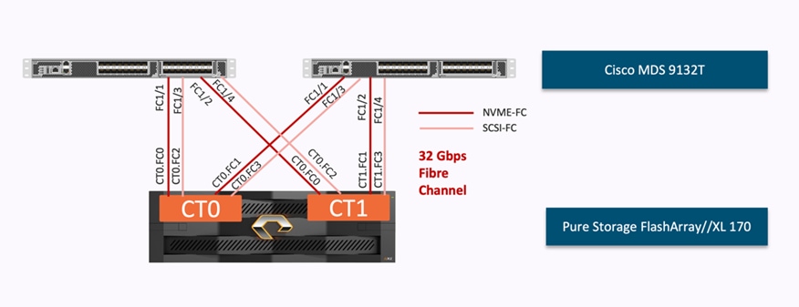
Pure Storage FlashArray//XL170 SAN Connectivity
For SAN connectivity, each Pure FlashArray controller is connected to both of Cisco MDS 9132T SAN switches using 32G Fibre Channel connections, as shown in Figure 31.
Figure 31. Pure Storage FlashArray Fibre Channel Connectivity.
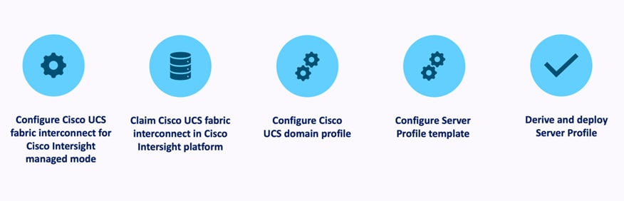
Cisco UCS X-Series Configuration – Cisco Intersight Managed Mode
Cisco Intersight Managed Mode standardizes policy and operation management for Cisco UCS X-Series. The compute nodes in Cisco UCS X-Series are configured using server profiles defined in Cisco Intersight. These server profiles derive all the server characteristics from various policies and templates. At a high level, configuring Cisco UCS using Intersight Managed Mode consists of the steps shown in Figure 32.
Figure 32. Configuration Steps for Cisco Intersight Managed Mode
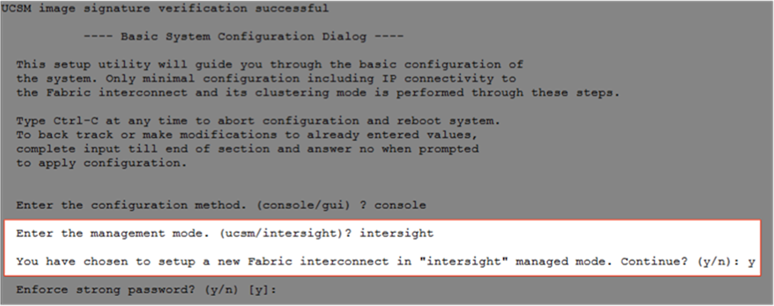
Set up Cisco UCS 6536 Fabric Interconnect for Cisco Intersight Managed Mode
During the initial configuration, for the management mode the configuration wizard enables customers to choose whether to manage the fabric interconnect through Cisco UCS Manager or the Cisco Intersight platform. Customers can switch the management mode for the fabric interconnects between Cisco Intersight and Cisco UCS Manager at any time; however, Cisco UCS FIs must be set up in Intersight Managed Mode (IMM) for configuring the Cisco UCS X-Series system. Figure 33 shows the dialog during initial configuration of Cisco UCS FIs for setting up IMM.
Figure 33. Fabric Interconnect Setup for Cisco Intersight Managed Mode
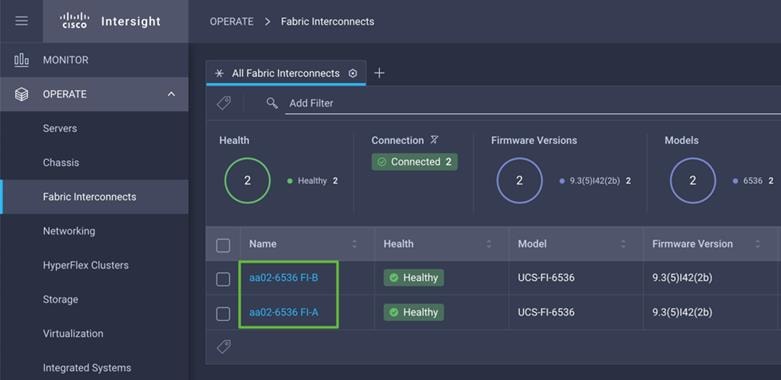
Claim a Cisco UCS Fabric Interconnect in the Cisco Intersight Platform
After setting up the Cisco UCS 6536 Fabric Interconnect for Cisco Intersight Managed Mode, FIs can be claimed to a new or an existing Cisco Intersight account. When a Cisco UCS Fabric Interconnect is successfully added to Cisco Intersight, all future configuration steps are completed in the Cisco Intersight portal.
Figure 34. Cisco Intersight: Fabric Interconnects
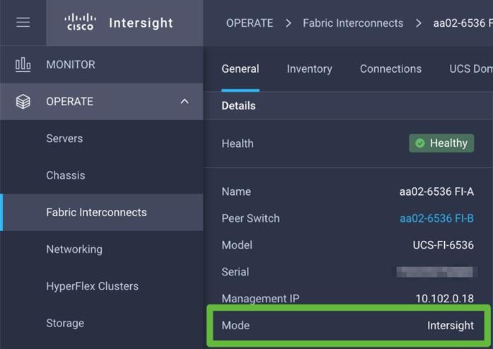
You can verify whether a Cisco UCS 6536 Fabric Interconnect is in Cisco UCS Manager managed mode or Cisco Intersight Managed Mode by clicking on the fabric interconnect name and looking at the detailed information screen for the FI, as shown in Figure 35.
Figure 35. Cisco UCS FI in Cisco Intersight Managed Mode
![]()
Cisco UCS Chassis Profile
A Cisco UCS Chassis profile configures and associates the chassis policy to a Cisco UCS chassis. The chassis profile feature is available in Intersight only if customers have installed the Intersight Essentials License. The chassis-related policies can be attached to the profile either at the time of creation or later.
The chassis profile in a FlashStack is used to set the power policy for the chassis. By default, UCS X-Series power supplies are configured in GRID mode, but power policy can be utilized to set the power supplies in non-redundant or N+1/N+2 redundant modes.
Cisco UCS Domain Profile
A Cisco UCS domain profile configures a fabric interconnect pair through reusable policies, allows configuration of the ports and port channels, and configures the VLANs and VSANs to be used in the network. It defines the characteristics of and configures the ports on the fabric interconnects. One Cisco UCS domain profile can be assigned to one fabric interconnect domain.
Some of the characteristics of the Cisco UCS domain profile in the FlashStack environment are:
· A single domain profile is created for the pair of Cisco UCS fabric interconnects.
· Unique port policies are defined for the two fabric interconnects.
· The VLAN configuration policy is common to the fabric interconnect pair because both fabric interconnects are configured for the same set of VLANs.
· The VSAN configuration policies (FC connectivity option) are unique for the two fabric interconnects because the VSANs are unique.
· The Network Time Protocol (NTP), network connectivity, and system Quality-of-Service (QoS) policies are common to the fabric interconnect pair.
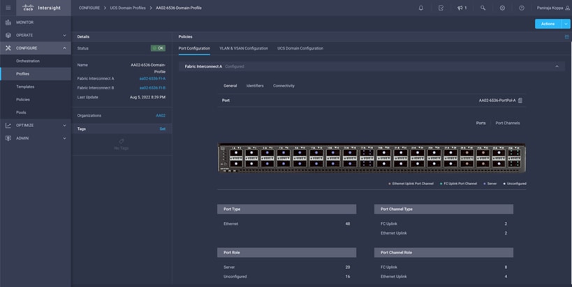
After the Cisco UCS domain profile has been successfully created and deployed, the policies including the port policies are pushed to Cisco UCS Fabric Interconnects. Cisco UCS domain profile can easily be cloned to install additional Cisco UCS systems. When cloning the UCS domain profile, the new UCS domains utilize the existing policies for consistent deployment of additional Cisco UCS systems at scale.
Figure 36. Cisco UCS Domain Profile
The Cisco UCS X9508 Chassis and Cisco UCS X210c M6 Compute Nodes are automatically discovered when the ports are successfully configured using the domain profile as shown in Figure 37, Figure 38, and Figure 39.
Figure 37. Cisco UCS X9508 Chassis Front View
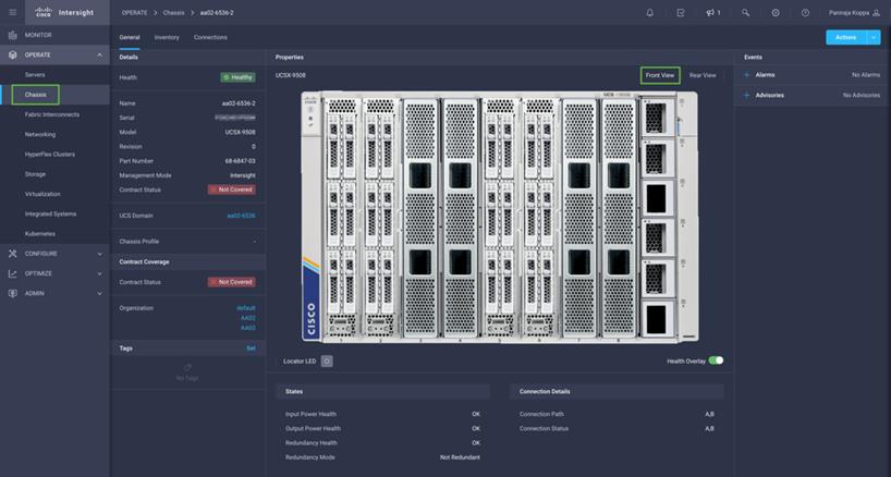
Figure 38. Cisco UCS X9508 Chassis Rear View
![]()
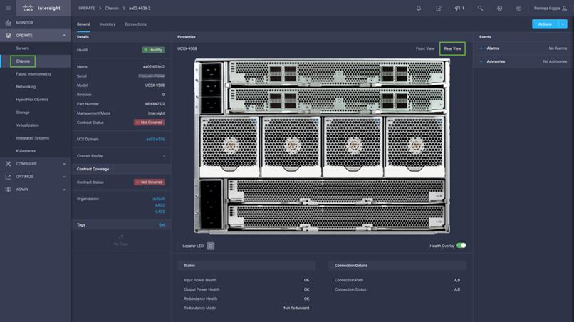
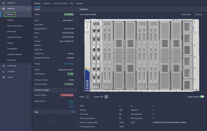
Figure 39. Cisco UCS X210c M6 Compute Nodes
Server Profile Template
A server profile template enables resource management by simplifying policy alignment and server configuration. A server profile template is created using the server profile template wizard. The server profile template wizard groups the server policies into the following four categories to provide a quick summary view of the policies that are attached to a profile:
· Compute policies: BIOS, boot order, and virtual media policies
· Network policies: adapter configuration, LAN connectivity, and SAN connectivity policies:
° The LAN connectivity policy requires you to create Ethernet network policy, Ethernet adapter policy, and Ethernet QoS policy.
° The SAN connectivity policy requires you to create Fibre Channel (FC) network policy, Fibre Channel adapter policy, and Fibre Channel QoS policy. SAN connectivity policy is only required for the FC connectivity option.
· Storage policies configure local storage and are not used in FlashStack
· Management policies: device connector, Intelligent Platform Management Interface (IPMI) over LAN, Lightweight Directory Access Protocol (LDAP), local user, network connectivity, Simple Mail Transfer Protocol (SMTP), Simple Network Management Protocol (SNMP), Secure Shell (SSH), Serial over LAN (SOL), syslog, and virtual Keyboard, Video, and Mouse (KVM) policies.
Some of the characteristics of the server profile template for FlashStack are:
· BIOS policy is created to specify various server parameters in accordance with FlashStack best practices.
· Boot order policy defines virtual media (KVM mapper DVD), all SAN paths for Pure Storage FlashArray (iSCSI or Fibre Channel interfaces), and UEFI Shell.
· IMC access policy defines the management IP address pool for KVM access.
· Local user policy is used to enable KVM-based user access.
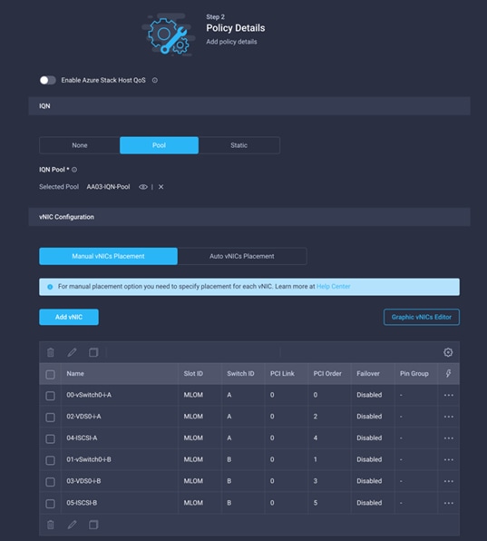
For the iSCSI boot from SAN configuration, LAN connectivity policy is used to create six virtual network interface cards (vNICs)—two for management virtual switch (vSwitch0), two for application Virtual Distributed Switch (VDS), and one each for iSCSI A/B vSwitches. Various policies and pools are also created for the vNIC configuration.
Figure 40. vNICs for iSCSI Boot Configuration
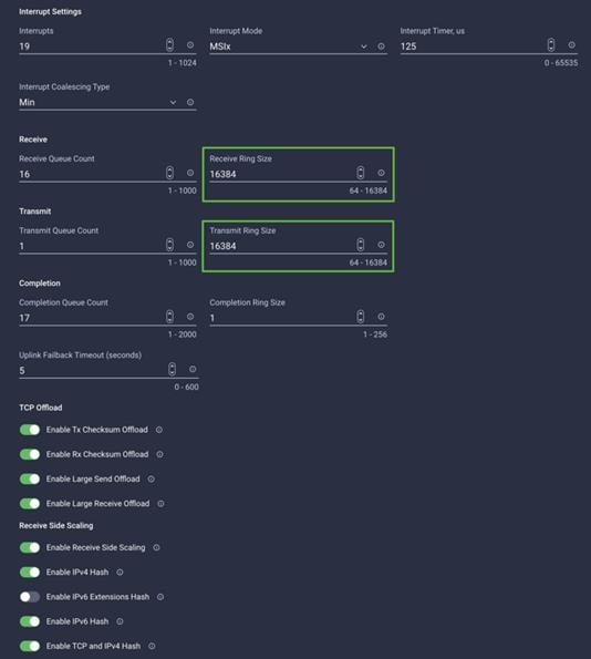
The 5th Generation Cisco UCS VIC 15231 supports up to 16384 Receive and Transmit ring sizes. Therefore, the Ethernet Adapter policy can be configured accordingly while creating iSCSI vNICs for optimized performance.
Figure 41. Higher Receive/Transmit ring sizes in 5th Generation Cisco UCS VIC
For the FC boot from SAN configuration, LAN connectivity policy is used to create four vNICs — two for management virtual switches (vSwitch0) and two for application VDS — along with various policies and pools.
For the FC connectivity option, SAN connectivity policy is used to create four virtual host bus adapters (vHBAs) — along with various policies and pools. 2 vHBAs (vHBA-A and vHBA-B) are of vHBA type “fc-initiator” and 2 vHBAs (vHBA-NVMe-A and vHBA-NVMe-B) are of vHBA type “fc-nvme-initiator”. The SAN connectivity policy is not required for iSCSI setup.
Figure 42. SAN Connectivity Policy
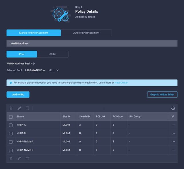
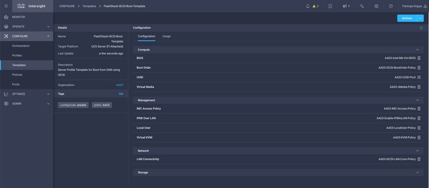
Figure 43 shows various policies associated with the server profile template.
Figure 43. Server Profile Template for iSCSI Boot from SAN
Derive and Deploy Server Profiles from the Cisco Intersight Server Profile Template
The Cisco Intersight server profile allows server configurations to be deployed directly on the compute nodes based on polices defined in the server profile template. After a server profile template has been successfully created, server profiles can be derived from the template and associated with the Cisco UCS X210c M6 Compute Nodes, as shown in Figure 44.
Figure 44. Deriving a Server Profile from Templates.
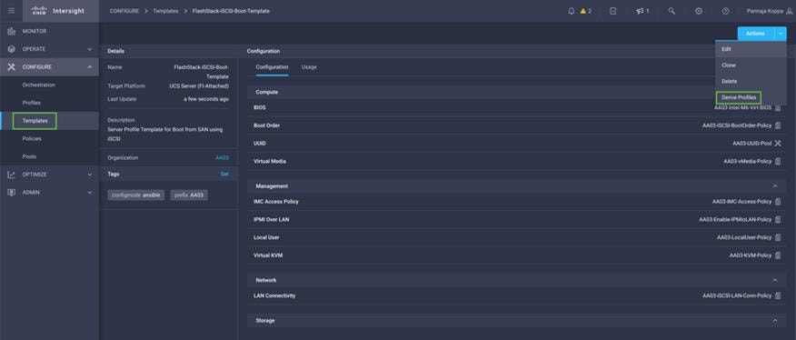
On successful deployment of the server profile, the Cisco UCS X210c M6 Compute Nodes are configured with parameters defined in the server profile and can boot from the storage LUN hosted on Pure Storage FlashArray.
Pure Storage FlashArray – Storage Design
To set up Pure Storage FlashArray customers must configure the following items:
· Volumes
° ESXi boot LUNs: These LUNs enable ESXi host boot from SAN functionality using iSCSI or Fibre Channel.
° The vSphere environment: vSphere uses the infrastructure datastore(s) to store the virtual machines.
· Hosts
° All FlashArray ESXi hosts are defined.
° Add every active initiator for a given ESXi host.
· Host groups
° All ESXi hosts in a VMware cluster are part of the host group.
° Host groups are used to mount VM infrastructure datastores in the VMware environment.
The volumes, interfaces, and VLAN/VSAN details are shown in Figure 45 and Figure 46 for iSCSI and Fibre Channel connectivity, respectively.
Figure 45. Pure Storage FlashArray Volumes and Interfaces – iSCSI Configuration
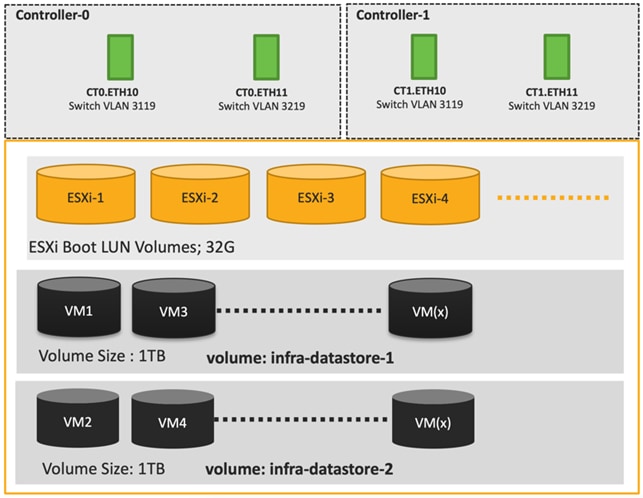
Along with SCSI-FC, this solution also implements NVMe using the FC-NVMe protocol over a SAN built using Cisco MDS switches. NVMe initiators consisting of Cisco UCS X210C servers installed with Cisco 15231 VIC adapters can access Pure FlashArray NVMe targets over Fibre Channel.
Each port on the Pure FlashArray can be configured as traditional scsi-fc port or as a nvme-fc port to support NVMe end-to-end via fibre channel from the host to storage array. Note that a FC port is either going to be SCSI or NVMe, not on the FlashArray.
Two ports on each Pure FlashArray controllers are configured as SCSI ports and the other two are configured as NVMe ports in this design validation as in Figure 46.
Figure 46. Pure Storage FlashArray Volumes and Interfaces – Fibre Channel Configuration
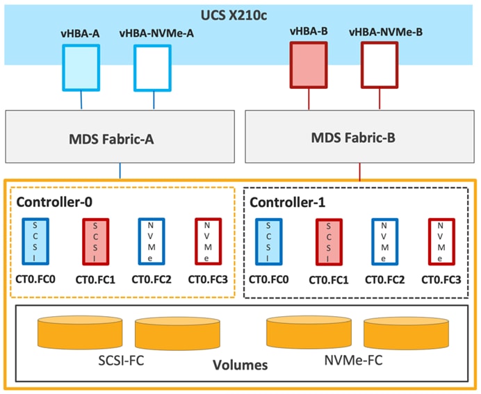
Cisco UCS provides a unified fabric that is an architectural approach delivering flexibility, scalability, intelligence, and simplicity. This flexibility allows Cisco UCS to readily support new technologies such as FC-NVMe seamlessly. In a Cisco UCS service profile, both standard Fibre Channel and FC-NVMe vHBAs can be created.
Both Fibre Channel and FC-NVMe vHBAs can exist in a Cisco UCS service profile on a single server. In the lab validation for this document, four vHBAs (one FC-NVME initiator on each Fibre Channel fabric and one Fibre Channel initiator on each Fibre Channel fabric) were created in each service profile. Each vHBA, regardless of type, was automatically assigned a worldwide node name (WWNN) and a worldwide port name (WWPN). The Cisco UCS fabric interconnects were in Fibre Channel end-host mode (NPV mode) and uplinked through a SAN port channel to the Cisco MDS 9132T switches in NPV mode. Zoning in the Cisco MDS 9132T switches connected the vHBAs to storage targets for both FC-NVMe and Fibre Channel. Single-initiator, multiple-target zones were used for both FCP and FC-NVMe.
The ESXi automatically connects to Pure FlashArray NVMe subsystem and discovers all shared NVMe storage devices that it can reach once the SAN zoning on MDS switches, and the configuration of host/host groups and volumes is completed on the Pure FlashArray.
Multiple vNICs (and vHBAs) are created for the ESXi hosts using the Cisco Intersight server profile and are then assigned to specific virtual and distributed switches. The vNIC and (optional) vHBA distribution for the ESXi hosts is as follows:
· Two vNICs (one on each fabric) for vSwitch0 to support core services such as management traffic.
· Two vNICs (one on each fabric) for vSphere Virtual Distributed Switch (VDS) to support customer data traffic and vMotion traffic.
· One vNIC each for Fabric-A and Fabric-B for iSCSI stateless boot. These vNICs are only required when iSCSI boot from SAN configuration is desired.
· One vHBA each for Fabric-A and Fabric-B for FC stateless boot. These vHBAs are only required when FC connectivity is desired.
Note: Typically, customers will either have iSCSI vNICs for IP based storage access or the FC vHBAs for Fibre Channel SAN connectivity.
Figure 47 and Figure 48 show the ESXi vNIC configurations in detail.
Figure 47. VMware vSphere – ESXi Host Networking for iSCSI Boot from SAN
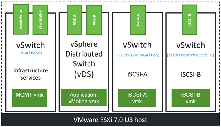
Figure 48. VMware vSphere – ESXi Host Networking for FC Boot from SAN
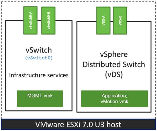
Cisco Intersight Integration with FlashStack
Cisco Intersight enhances the ability to provide complete visibility, orchestration, and optimization across all elements of FlashStack datacenter. This empowers customers to make intelligent deployment decisions, easy management, optimize cost and performance and maintain supported configurations for their infrastructure.
Cisco Intersight works with Pure Storage FlashArray, VMware vCenter using third-party device connectors. Since third-party infrastructure does not contain any built-in Cisco Intersight device connector, Cisco Intersight Assist virtual appliance enables Cisco Intersight to communicate with these non-Cisco devices. Also, Physical, and logical inventories of Ethernet and Storage area networks are available within Intersight.
Note: A single Cisco Intersight Assist virtual appliance can support both Pure Storage FlashArray and VMware vCenter.
Cisco Intersight integration with VMware vCenter, Pure Storage Flash Arrays, Nexus and MDS switches enables you to perform following tasks right from the Intersight dashboard:
· Monitor the virtualization of storage and network environment.
· Add various dashboard widgets to obtain useful at-a-glance information.
· Perform common Virtual Machine tasks such as power on/off, remote console and so on.
· Orchestration of Virtual, Storage and network environment to perform common configuration tasks.
· Extend optimization capability for entire FlashStack datacenter.
The following sections explain the details of these operations. Since Cisco Intersight is a SaaS platform, the monitoring and orchestration capabilities are constantly being added and delivered seamlessly from the cloud.
Note: The monitoring capabilities and orchestration tasks and workflows listed below provide an in-time snapshot for your reference. For the most up to date list of capabilities and features, customers should use the help and search capabilities in Cisco Intersight.
Figure 49. Managing Pure Storage FlashArray and VMware vCenter through Cisco Intersight using Intersight Assist
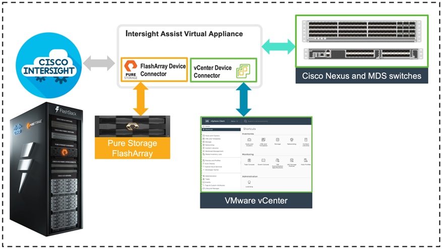
Licensing Requirement
To integrate and view various Pure Storage FlashArray and VMware vCenter parameters from Cisco Intersight, a Cisco Intersight Advantage license is required. To use Cisco Intersight orchestration and workflows to provision the storage and virtual environments, an Intersight Premier license is needed.
For more information about the licensing requirements, go to: https://www.intersight.com/help/saas/getting_started/licensing_requirements
Integrate Cisco Intersight with Pure Storage FlashArray
To integrate Pure Storage FlashArray with the Cisco Intersight platform, you must deploy a Cisco Intersight Assist virtual appliance and claim Pure Storage FlashArray as a target in the Cisco Intersight application, as shown in Figure 50.
Figure 50. Claiming Pure Storage FlashArray as a Target in Cisco Intersight
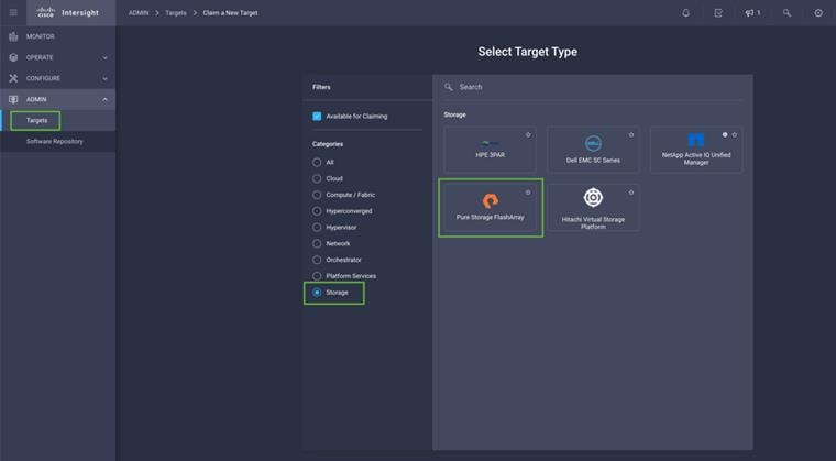
Obtain Storage-level Information
After successfully claiming Pure Storage FlashArray as a target, customers can view storage-level information in Cisco Intersight.
Figure 51. Pure Storage FlashArray Information in Cisco Intersight
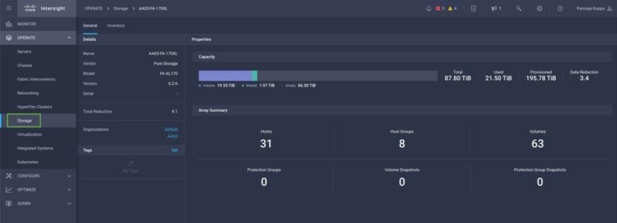
Table 6 lists some of the Pure Storage FlashArray information presented through Cisco Intersight.
Table 6. Pure Storage FlashArray Information in Cisco Intersight
| Category |
Name |
Details |
| General |
Name |
Name of the controller |
| Vendor |
Pure Storage |
|
| Model |
Pure Storage FlashArray model information (for example, FA-X50R3) |
|
| Version |
Software version |
|
| Serial |
Serial number |
|
| Data reduction |
Storage efficiency |
|
| Total reduction |
Storage efficiency |
|
| Monitoring |
Capacity |
Total, used, and provisioned system capacity |
| Array Summary |
Summary of hosts, host groups, volumes, and so on, in the system |
|
| Logical Inventory |
Hosts |
Hosts defined in the system and associated ports, volumes, and protection of group information |
| Host groups |
Host groups defined in the system and associated hosts, volumes, and protection of groups in the system |
|
| Volumes |
Configured volumes and volume-specific information such as capacity, data reduction, and so on. |
|
| Protection group |
Protection groups defined in the system and associated targets, members, and so on. |
|
| Hardware Inventory |
Controllers |
FlashArray controllers and their state, version, and model information |
| Drives |
Storage drive–related information, including type and capacity information |
|
| Ports |
Information related to physical ports, including World Wide Port Name (WWPN) and iSCSI Qualified Name (IQN) information |
Storage Widget in the Dashboard
Customers can also add the storage dashboard widgets to Cisco Intersight for viewing Pure Storage FlashArray at a glance information on the Cisco Intersight dashboard, as shown in Figure 52.
Figure 52. Storage Widgets in Cisco Intersight Dashboard
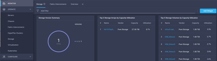
These storage widgets provide useful information such as:
· Storage versions summary, providing information about the software version and the number of storage systems running that version
· Storage arrays and capacity utilization
· Top-five storage volumes by capacity utilization
Cisco Intersight Orchestrator – Pure Storage FlashArray
Cisco Intersight Orchestrator provides various workflows that can be used to automate storage provisioning. Some of the sample storage workflows available for Pure Storage FlashArray are listed in Table 7.
Table 7. Pure Storage FlashArray Workflows in Cisco Intersight Orchestrator
| Name |
Details |
| New storage host |
Create a new storage host; if a host group is provided as input, then the host is added to the host group. |
| New storage host group |
Create a new storage host group; if hosts are provided as inputs, the workflow will add the hosts to the host group. |
| New VMFS Datastore |
Create a storage volume and build a VMFS datastore on the volume. |
| Remove storage host |
Remove a storage host. If a host group name is provided as input, the workflow will also remove the host from the host group. |
| Remove storage host group |
Remove a storage host group. If hosts are provided as input, the workflow will remove the hosts from the host group. |
| Remove VMFS datastore |
Remove a VMFS datastore and remove the backing volume from the storage device. |
| Update storage host |
Update the storage host details. If the inputs for a task are provided, then the task is run; otherwise, it is skipped. |
| Update VMFS datastore |
Expand a datastore on the hypervisor manager by extending the backing storage volume to specified capacity, and then expanding the data store to use the additional capacity. |
In addition to the above workflows, Cisco Intersight Orchestrator also provides many storage and virtualization tasks for customers to create custom workflow based on their specific needs. A sample subset of these tasks is highlighted in Figure 53.
Figure 53. Storage Tasks for Pure Storage FlashArray
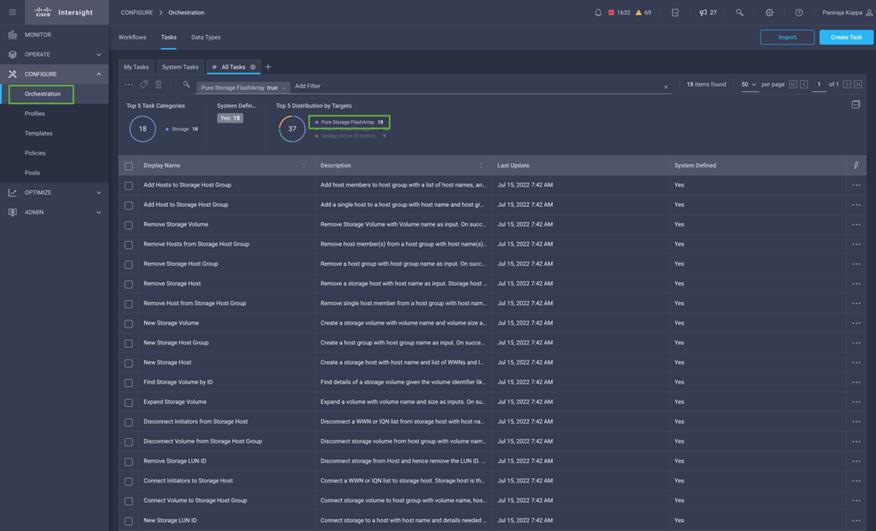
Integrate Cisco Intersight with VMware vCenter
To integrate VMware vCenter with Cisco Intersight, VMware vCenter can be claimed as a target using Cisco Intersight Assist Virtual Appliance, as shown in Figure 54.
Figure 54. Claim VMware vCenter in Cisco Intersight as a Target
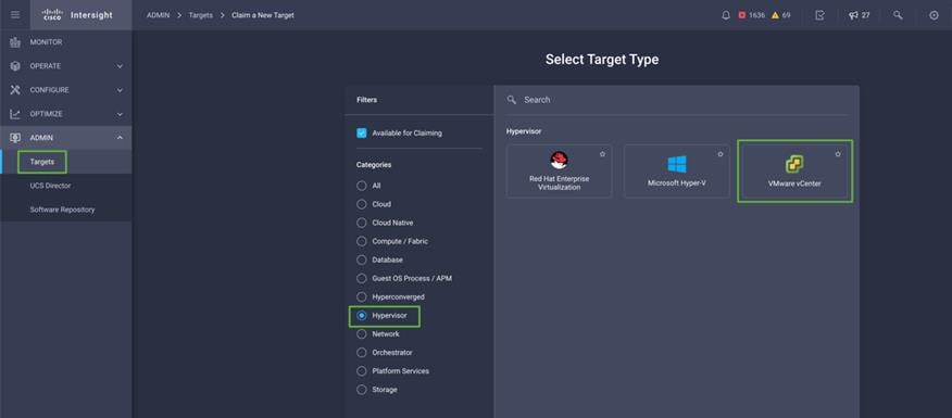
Obtain Hypervisor-level Information
After successfully claiming the VMware vCenter as a target, customers can view hypervisor-level information in Cisco Intersight including hosts, VMs, clusters, datastores, and so on.
Figure 55. VMware vCenter Information in Cisco Intersight
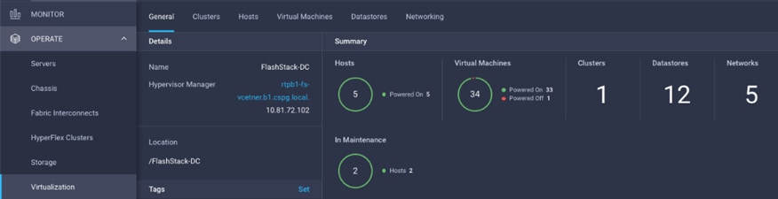
Table 8 lists some of the main virtualization properties presented in Cisco Intersight.
Table 8. Virtualization (VMware vCenter) Information in Cisco Intersight
| Category |
Name |
Details |
| General |
Name |
Name of the data center |
| Hypervisor manager |
Host name or IP address of the vCenter |
|
| Clusters |
Name |
Name of the cluster |
| Data center |
Name of the data center |
|
| Hypervisor type |
ESXi |
|
| Hypervisor manager |
vCenter IP address or the host name |
|
| CPU capacity |
CPU capacity in the cluster (GHz) |
|
| CPU consumed |
CPU cycles consumed by workloads (percentage and GHz) |
|
| Memory capacity |
Total memory in the cluster (GB) |
|
| Memory consumed |
Memory consumed by workloads (percentage and GB) |
|
| Total cores |
All the CPU cores across the CPUs in the cluster |
|
| VMware cluster information allows customers to access additional details about hosts and virtual machines associated with the cluster. |
||
| Hosts |
Name |
Host name or IP address |
| Server |
Server profile associated with the ESXi host |
|
| Cluster |
Cluster information if the host is part of a cluster |
|
| Data center |
VMware data center |
|
| Hypervisor type |
ESXi |
|
| Hypervisor manager |
vCenter IP address of host name |
|
| Uptime |
Host uptime |
|
| Virtual Machines |
Number and state of VMs running on a host |
|
| CPU Information |
CPU cores, sockets, vendor, speed, capacity, consumption, and other CPU related information |
|
| Memory Information |
Memory capacity and consumption information |
|
| Hardware Information |
Compute node hardware information such as serial number, model etc. |
|
| Host information allows customers to access additional details about clusters, VMs, datastores, and networking related to the current ESXi host. |
||
| Virtual Machines |
Name |
Name of the VM |
| Guest OS |
Operating system, for example, RHEL, CentOS, etc. |
|
| Hypervisor type |
ESXi |
|
| Host |
ESXi host information for the VM |
|
| Cluster |
VMware cluster name |
|
| Data center |
VMware data center name |
|
| IP address |
IP address(s) assigned to the VM |
|
| Hypervisor manager |
IP address of host name of the vCenter |
|
| Resource Information |
CPU, memory, disk, and network information |
|
| Guest Information |
Hostname, IP address and operating system information |
|
| VM information allows customers to access additional details about clusters, hosts, datastores, networking, and virtual disks related to the current VM. |
||
| Datastores |
Name |
Name of the datastore in VMware vCenter |
| Type |
VMFS or NFS etc. |
|
| Accessible |
Yes, if datastore is accessible; No, if datastore is inaccessible |
|
| Thin provisioning |
Yes, if thin provisioning is allowed; No if thin provisioning is not allowed |
|
| Multiple host access |
Yes, if multiple hosts can mount the datastore; No, if the datastore only allows a single host |
|
| Storage capacity |
Space in GB or TB |
|
| Storage consumes |
Percentage and GB |
|
| Data center |
Name of VMware vCenter data center |
|
| Hypervisor manager |
vCenter hostname or IP address |
|
| Datastore Cluster |
Datastore cluster information if datastore cluster is configured |
|
| Hosts and Virtual Machines |
Number if hosts connected to a datastore and number of VM hosted on the datastore |
|
| Datastore information allows customers to access additional details about hosts and VMs associated with the datastore. |
||
Interact with Virtual Machines
VMware vCenter integration with Cisco Intersight allows customers to directly interact with the virtual machines (VMs) from the Cisco Intersight dashboard. In addition to obtaining in-depth information about a VM, including the operating system, CPU, memory, host name, and IP addresses assigned to the virtual machines, customers can use Cisco Intersight to perform following actions on the virtual machines (Figure 56).
· Launch VM console
· Power off
· Reset
· Shutdown guest OS
· Restart guest OS
· Suspend
Figure 56. Virtual Machine Actions in Cisco Intersight
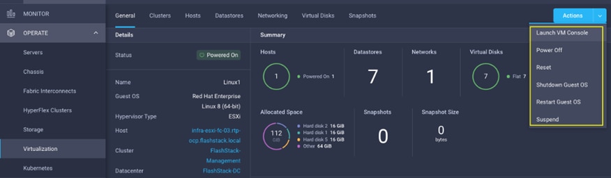
Cisco Intersight Orchestrator – VMware vCenter
Cisco Intersight Orchestrator provides various workflows that can be used for the VM and hypervisor provisioning. Some of the sample workflows available for VMware vCenter are captured in Table 9.
Table 9. VMware vCenter Workflows in Cisco Intersight Orchestrator
| Name |
Details |
| New VMFS Datastore |
Create a storage volume and build VMFS datastore on the volume. |
| New NAS Datastore |
Create a NFS storage volume and build NAS datastore on the volume. |
| New Virtual Machine |
Create a new virtual machine on the hypervisor from an OVA or OVF file. Datastore, Host/Cluster, and Image URL fields are mandatory. All other inputs are optional. |
| Remove VMFS Datastore |
Remove VMFS datastore and remove the backing volume from the storage device. When a datastore is removed from a host, it is destroyed and will disappear from all hosts that have access to it. If a cluster name is provided, the datastore is removed from all hosts in the cluster. |
| Remove NAS Datastore |
Remove the NAS datastore and the underlying NFS storage volume. When a datastore is removed from a host, it is destroyed and will disappear from all hosts that have access to it. If a cluster name is provided, the datastore is removed from all hosts in the cluster. |
| Update VMFS Datastore |
Expand a datastore on hypervisor manager by extending the backing storage volume to specified capacity, and then grow the datastore to utilize the additional capacity. |
| Update NAS Datastore |
Update NAS datastore by expanding capacity of the underlying NFS volume. The expanded capacity is visible to all hosts connected to the datastore. |
In addition to the above workflows, Cisco Intersight Orchestrator provides many tasks for customers to create custom workflows depending on their specific requirements. A sample subset of these tasks is highlighted in Figure 57.
Figure 57. VMware vCenter Tasks in Cisco Intersight Orchestrator
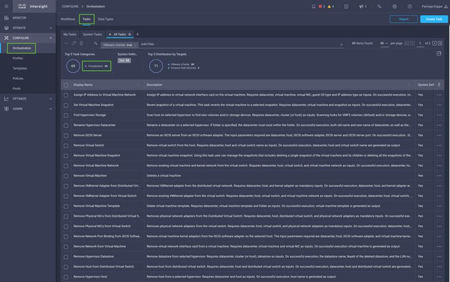
Integrate Cisco Intersight with Cisco Nexus and MDS Switches
To integrate Cisco Nexus and MDS switches with Cisco Intersight, Cisco Nexus and MDS switches can be claimed as a target using Cisco Intersight Assist Virtual Appliance deployed earlier.
Figure 58. Claiming Cisco Nexus and MDS targets
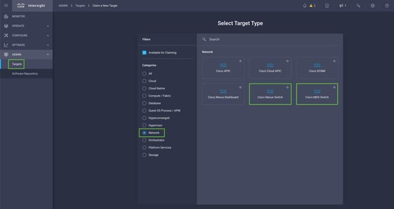
Obtain Data Center Network Information
After successfully claiming the Cisco Nexus and MDS switches as targets, customers can view their Ethernet and SAN details in Cisco Intersight including Physical and logical inventory.
Figure 59. Listing Ethernet and SAN Switches
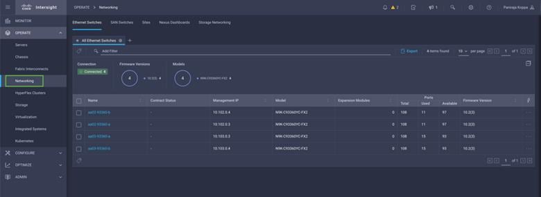
Table 10 lists some of the Cisco Nexus switch information presented through Cisco Intersight.
Table 10. Cisco Nexus Information in Cisco Intersight
| Category |
Name |
Details |
| Table View |
Name |
The name of the ethernet switch. |
| Contract Status |
The status of the service contract for the ethernet switch, based on the current validity of their associated contracts. |
|
| Management IP |
The static IPv4 or IPv6 address for the management port on the switch. |
|
| Model |
Displays the model number of the ethernet switch. |
|
| Expansion Modules |
The total number of expansion modules in the switch available to expand Ethernet, FCoE, Fibre Channel ports, and so on. |
|
| Ports |
Displays the total ports, used number of ports, and the available ports. |
|
| Firmware Version |
The firmware version running on the switch. |
|
| General |
Name |
Name of the controller |
| Vendor |
Pure Storage |
|
| Model |
Pure Storage FlashArray model information (for example, FA-X50R3) |
|
| Version |
Software version |
|
| Serial |
Serial number |
|
| Data reduction |
Storage efficiency |
|
| Total reduction |
Storage efficiency |
|
| Logical Inventory |
System |
General — Configuration modified time, system uptime, and firmware version. NTP — Network Time Protocol (NTP) server IP address, NTP stratum, poll interval, and virtual routing and forwarding (VRF) name. DNS — Domain Name Server (DNS) details for the ethernet switch—VRF name, default domain, additional domains, and name servers. |
| Interfaces |
Displays physical and logical interface details. |
|
| L2 Neighbor |
Displays L2 neighbor details for the ethernet switch—local interface, hostname, neighbor device, device capability, interface, and management address. |
|
| VLANs |
Displays the VLAN details for the ethernet switch—name, ID, admin state, and interfaces. |
|
| VRFs |
Displays the details of the virtual routing and forwarding instances configured on the switch. |
|
| Licenses |
Displays the details of Traditional or Classic Licensing and Smart Software Licensing for the ethernet switch—file ID, host ID, and feature. |
|
| Features |
Displays a list of features available on the ethernet switch along with the admin state. |
|
| Physical Inventory |
Ports |
Displays the details for the ethernet switch port details—name, operational state, admin state, MAC, transceiver name, and transceiver details. |
| Supervisor Modules |
Displays the details for the ethernet switch supervisor modules details—name, operational state, hardware version, model, and description. |
|
| Switching Modules |
Displays the details for the ethernet switch switching modules details—name, model, status, type, and hardware version. |
|
| CPUs |
Displays the details for the ethernet switch CPU details—name, architecture, model, speed, cores, and vendor. |
|
| Power |
Displays the details for the ethernet switch power supply details—name, ID, serial, model, operational state, and vendor. |
|
| Thermal |
Displays the details for the fan modules—name, ID, operational state, and model |
When you select a SAN switch in the SAN Switches table view, the SAN Switch page displays the information specific to the selected device. Details are listed in Table 11.
Table 11. Cisco MDS Information in Cisco Intersight
| Category |
Name |
Details |
| General |
Name |
The name of the SAN switch. |
| Type |
The type of SAN switch. |
|
| Serial |
The serial number of the switch. |
|
| Contract Status |
The status of the service contract for the SAN switch, based on the current validity of their associated contracts. |
|
| Model |
The model number of the SAN switch. |
|
| Vendor |
The Name of the vendor of the switch. |
|
| Revision |
The revision number of the chassis. |
|
| Expansion Modules |
The total number of expansion modules in the switch available to expand Ethernet, FCoE, Fibre Channel ports, and so on. |
|
| Part Number |
The part number of the chassis. |
|
| Management IP |
The static IPv4 or IPv6 address for the management port on the switch. |
|
| Firmware Version |
The firmware version running on the switch. |
|
| System Uptime |
The system uptime for the SAN switch. |
|
| Organizations |
The organizations to which the switch is assigned. |
|
| Ports |
Displays the total ports, used number of ports, and the available ports. |
|
| Tag |
The tag for the device in the key:value format. |
|
| Logical Inventory |
System |
Displays the details for the SAN switch—configuration modified time, system uptime, firmware version, DNS server details, and NTP server details. |
| Port Channels |
Displays the port channel details for the SAN switch—name, operational state, WWN, and interface mode. |
|
| FC Port Neighbor |
Displays the fabric channel port neighbor details for the SAN switch—local interface, hostname, device class, interface, and WWN. |
|
| VSAN |
Displays the virtual storge area network details for the SAN switch—name, ID, operational state, admin state, interop mode, and load balancing. |
|
| Features |
Displays a list of features available on a switch along with the index and admin state. |
|
| Licenses |
Displays the details of the licenses for the SAN switch—file ID, host ID, feature, and vendor. |
|
| Physical Inventory |
Ports |
Displays the details for the SAN switch port details—name, operational state, admin state, WWN, transceiver name, transceiver details, and interface mode. |
| Supervisor Modules |
Displays the details for the SAN switch supervisor modules details—name, operational state, hardware version, model, and description. |
|
| Switching Modules |
Displays the details for the SAN switch switching modules details—name, model, status, type, and hardware version. |
|
| CPUs |
Displays the details for the SAN switch CPU details–name, architecture, model, speed, cores, and vendor. |
|
| Power |
Displays the details for the SAN switch power supply details—name, ID, serial, model, operational state, and vendor. |
|
| Thermal |
Displays the details for the fan modules—name, ID, operational state, and model. |
Cisco Intersight Orchestrator – Ethernet and Storage network
Cisco Intersight Orchestrator also provides many networking tasks for customers to create custom workflow based on their specific needs. A sample list of these tasks for Cisco Nexus is highlighted in Figure 60.
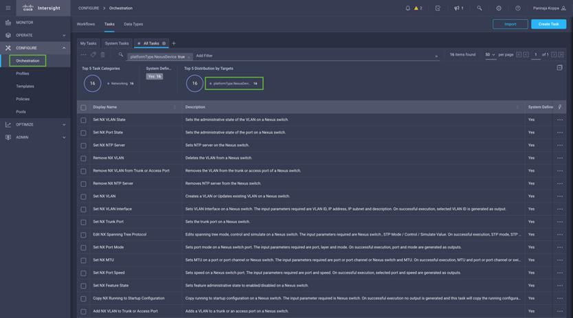
Sample list of these tasks for Cisco MDS is highlighted in Figure 61.
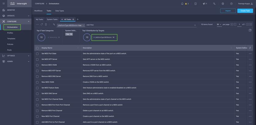
Some of the key design considerations for the FlashStack with Cisco UCS X-Series and VMware 7.0 U3 are explained in this section.
Management Design Considerations
· Out-of-band Management Network
The management interface of every physical device in FlashStack is connected to a dedicated out-of-band management switch, which can be part of the existing management infrastructure in a customer’s environment. The out-of-band management network provides management access to all the devices in FlashStack for initial and on-going configuration changes. The routing and switching configuration for this network is independent of FlashStack deployment and therefore changes in FlashStack configurations do not impact management access to the devices.
· In-band Management Network
The in-band management VLAN configuration is part of FlashStack design. The in-band VLAN is configured on Nexus switches and Cisco UCS within the FlashStack solution to provide management connectivity for vCenter, ESXi and other management components. The changes to FlashStack configuration can impact the in-band management network and misconfigurations can cause loss of access to the management components hosted on the FlashStack.
Cisco Nexus 9000 Series vPC Best Practices
The following Cisco Nexus 9000 vPC design best practices and recommendations were used in this design:
· vPC peer keepalive link should not be routed over a vPC peer-link.
· The out-of-band management network is used as the vPC peer keepalive link in this design.
· Only vPC VLANs are allowed on the vPC peer-links. For deployments that require non-vPC VLAN traffic to be carried across vPC peer switches, a separate Layer 2 link should be deployed.
QoS Considerations
When using iSCSI for storage traffic, it may be necessary to prioritize the storage traffic over vMotion traffic if network bandwidth is constrained. FlashStack design allows customers to easily increase network bandwidth by adding additional links. Configuring QoS to prioritize storage traffic is also supported but QoS should always include a comprehensive plan for the individual customer environment.
Cisco UCS Fabric Interconnect (FI) Best Practices
Cisco UCS Fabric Interconnect is configured in default end-host mode. In this mode, the FIs will only learn MAC addresses from devices connected on Server and Appliance ports and FIs do not run spanning-tree. Loops avoidance is achieved using a combination of Deja-Vu check and Reverse Path Forwarding (RFP).
Oversubscription
The solution enables 100 Gigabit network bandwidth end-to-end which is highly performant. But to reduce the impact of an outage or scheduled downtime, it is a good practice to overprovision link bandwidth to enable a sustainable performance profile during component failure. Appropriately sized oversubscription protects workloads from being impacted by a reduced number of paths during a failure or maintenance event. Oversubscription can be achieved by increasing the number of physically cabled connections between storage and compute.
SAN Topology
For best performance, the ideal Fibre Channel SAN topology is a “Flat Fabric” where the FlashArray is only one hop away from any applications accessing the storage because additional hops add additional latency. Similarly, for iSCSI-based SAN design, it is recommended to reduce the number of network hops and not enable routing for the iSCSI storage LAN.
Pure Storage FlashArray Considerations
· Connectivity
° Each FlashArray Controller should be connected to BOTH storage fabrics (A/B).
° Make sure to include additional I/O Cards which support 100 GE are installed in original FlashArray BOM
° Pure Storage offers up to 32Gb FC support on the latest FlashArray//X and up to 64Gb FC support on the latest FlashArray//XL series arrays. Always make sure the correct number of HBAs and SFPs (with appropriate speed) are included in the original FlashArray BOM.
° For NVME-FC, make sure to include the I/O controller with service “nvme-fc” enabled.
· Host Groups and Volumes
It is a best practice to map Hosts to Host Groups and the Host Groups to Volumes in Purity. This ensures the Volume is presented on the same LUN ID to all hosts and allows for simplified management of ESXi Clusters across multiple nodes.
· Size of the Volume
Purity removes the complexities of aggregates and RAID groups. When managing storage, a volume should be created based on the size required and purity takes care of availability and performance via RAID-HD and DirectFlash software. Customers can create 1 10-TB volume or 10 1-TB volumes and the performance and availability for these volumes will always be consistent. This feature allows customers to focus on recoverability, manageability, and administrative considerations of volumes instead of dwelling on availability or performance.
vCenter Deployment Consideration
While hosting the vCenter on the same ESXi hosts that the vCenter will manage is supported, it is a best practice to deploy the vCenter on a separate management infrastructure. The ESXi hosts in this new FlashStack with Cisco UCS X-Series environment can also be added to an existing customer vCenter. The in-band management VLAN will provide connectivity between the vCenter and the ESXi hosts deployed in the new FlashStack environment.
· Jumbo Frames
An MTU of 9216 is configured at all network levels to allow jumbo frames as needed by the guest OS and application layer. The MTU value of 9000 is used on all the vSwitches and vSphere Distributed Switches (VDS) in the VMware environment.
· Boot From SAN
When utilizing Cisco UCS Server technology with shared storage, it is recommended to configure boot from SAN and store the boot LUNs on remote storage. This enables architects and administrators to take full advantage of the stateless nature of Cisco UCS X-Series Server Profiles for hardware flexibility across the server hardware and overall portability of server identity. Boot from SAN also removes the need to populate local server storage thereby reducing cost and administrative overhead.
· UEFI Secure Boot
This validation of FlashStack uses Unified Extensible Firmware Interface (UEFI) Secure Boot. UEFI is a specification that defines a software interface between an operating system and platform firmware. With UEFI secure boot enabled, all executables, such as boot loaders and adapter drivers, are authenticated by the BIOS before they can be loaded. Cisco UCS X210C compute nodes also contain a Trusted Platform Module (TPM). VMware ESXi 7.0 U2 supports UEFI Secure Boot and VMware vCenter 7.0 U2 supports UEFI Secure Boot Attestation between the TPM module and ESXi, validating that UEFI Secure Boot has properly taken place.
· Pure Storage FlashArray considerations for VMware vSphere 7.0
The following Pure Storage design considerations and best practices for VMware vSphere were followed in this FlashStack design:
° FlashArray volumes are automatically presented to VMware vSphere using the round robin Path Selection Policy (PSP) and appropriate vendor Storage Array Type Plugin (SATP) for vSphere 7.0.
° vSphere 7.0 uses the Latency SATP that was introduced in vSphere 6.7U1. This replaces the I/O operations limit of 1 SATP, which was the default from vSphere 6.5U1. It is recommended to set samplingCycles - 16 and latencyEval-Time - 180000 ms.
° DataMover.HardwareAcceleratedMove, DataMover.HardwareAcceleratedInit, and VMFS3.HardwareAcceleratedLocking should all be enabled.
° When using iSCSI connected FlashArray volumes, it is recommended to set TCP DelayedAck to false (disabled) and LoginTimeout to 30 seconds.
° Queue depths should be left at the default. Changing queue depths on the ESXi host is a tweak and should only be examined if a performance problem (high latency) is observed.
° Install VMware tools or Open VM tools whenever possible.
° When mounting snapshots, use the ESXi resignature option and avoid force-mounting.
° Ensure all ESXi hosts are connected to both FlashArray controllers and at a minimum, ensure two physical paths to each controller to achieve complete redundancy.
° Configure Host Groups on the FlashArray identical to clusters in vSphere. For example, if a cluster has four hosts in it, create a corresponding Host Group on the relevant FlashArray with exactly those four hosts.
° Use Paravirtual SCSI adapters for virtual machines whenever possible.
° Atomic Test and Set (ATS) is required on all Pure Storage volumes. This is a default configuration, and no configuration changes are needed.
Note: VMware supports: NVMe-RDMA and NVMe-FC for VMFS only, there is no vVol support.
For more information about the VMware vSphere Pure Storage FlashArray Best Practices please refer to: https://support.purestorage.com/Solutions/VMware_Platform_Guide/User_Guides_for_VMware_Solutions/FlashArray_VMware_Best_Practices_User_Guide/Quick_Reference%3A_Best_Practice_Settings
VMware Virtual Volumes
This validation of FlashStack supports VMware Virtual Volumes (vVols) for customers looking for more granular control of their SAN environment. vVol is a storage technology that provides policy-based, granular storage configuration and control of VMs. Through API-based interaction with an underlying array, VMware administrators can maintain storage configuration compliance using only native VMware interfaces. The Pure Storage FlashArray Plugin for the vSphere Web Client makes it possible to create, manage, and use vVols from within the Web Client.
Figure 62. vSphere Virtual Volumes Architecture
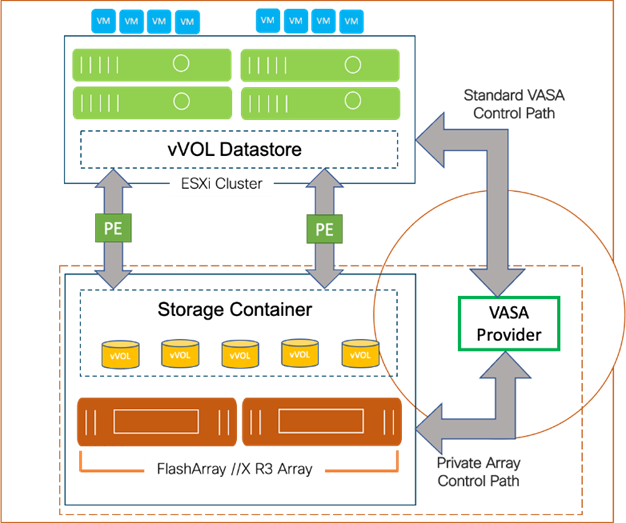
To start using vVOLs with the Pure Storage FlashArray, the FlashArray storage providers must be registered in vCenter Server. The Protocol Endpoint (PE) is then connected to the hostgroup and the vVol datastore is created.
FlashArray Virtual Volumes Considerations
VMware vCenters in Enhanced Linked Mode will each be able to communicate with the same FlashArray. However, vCenters that are not in Enhanced Linked Mode must use CA-Signed Certificates to use the same FlashArray. To support multiple VMware vCenters accessing the same FlashArray for vVols, the vCenters should be configured in Enhanced Linked Mode.
A VM's Config vVol stores the files required to build and manage the VM. Ensure that the Config vVol is part of an existing FlashArray Protection Group. Alternately, if customers are using storage policy that include snapshot or if customers prefer manual snapshots, Config vVol should be part of these snapshots. This will help with the VM recovery process if the VM is deleted.
When a Storage Policy is applied to a vVol VM, the volumes associated with that VM are added to the designated protection group. If replication is part of Storage Policy, the number of VMs using the storage policy as well as the replication groups becomes an important consideration. A large number of VMs with high change rate could cause replication to miss its schedule due to increased replication bandwidth and time needed to complete the scheduled snapshot. Pure Storage recommends vVol VMs with Storage Policies applied to be balanced between protection groups. To understand FlashArray limits on volume connections per host, volume count and snapshot Count, review the following document: https://support.purestorage.com/FlashArray/PurityFA/General_Troubleshooting/Pure_Storage_FlashArray_Limits.
Pure Storage FlashArray Best Practices for vVols
Along with the above Pure Storage vVol considerations, following best practices should be considered during implementation of vVols:
· Create a Local FlashArray Array-Admin user to register the storage provider instead of using the local “pure user” account.
· Use the Round Robin pathing policy (default) for the Protocol Endpoint.
· Use the Pure Storage Plugin for the vSphere Client to register the FlashArray storage provider and mount the vVols datastore.
· When registering the storage providers manually, register both VASA providers with CT0.ETH0 and CT1.ETH0. The support for ETH1 interfaces are supported if a custom certificate is used.
· Manually mounting the vVol datastore requires users to connect the protocol endpoint (PE).
· A single PE utilizing the default device queue depth is sufficient in the design.
· VM Templates associated with the vVol VMs should also be kept on vVols.
· VMDK resizing of VMs that resides on a vVol should be completed from vSphere Client and not from FlashArray GUI.
· ESXi Hosts, vCenter Server and FlashArray should synchronize time to the same NTP Server.
· TCP port 8084 must be open and accessible from vCenter Servers and ESXi hosts to the FlashArray that will be used for vVol.
· vCenter Server should not reside on vVols.
· The FlashArray Protocol Endpoint object 'pure-protocol-endpoint' must exist. The FlashArray admin must not rename, delete or otherwise edit the default FlashArray Protocol Endpoint.
For more information on vVols best practices, refer to the following summary: https://support.purestorage.com/Solutions/VMware_Platform_Guide/User_Guides_for_VMware_Solutions/Virtual_Volumes_User_Guide/vVols_User_Guide%3A_Best_Practice_Summary.
NVMe over Fabrics
NVMe over Fabrics (NVMe-oF) is an extension of the NVMe network protocol to Ethernet and Fibre Channel delivering faster and more efficient connectivity between storage and servers as well as a reduction in CPU utilization of application host servers. This validation of FlashStack supports NVMe over Fibre Channel (NVMe/FC) to provide the high-performance and low-latency benefits of NVMe across fabrics. In this solution, NVMe initiators consisting of Cisco UCS X210c compute nodes access Pure FlashArray NVMe targets over Fibre Channel.
Figure 63. End-to-End NVMe over Fibre Channel Connectivity
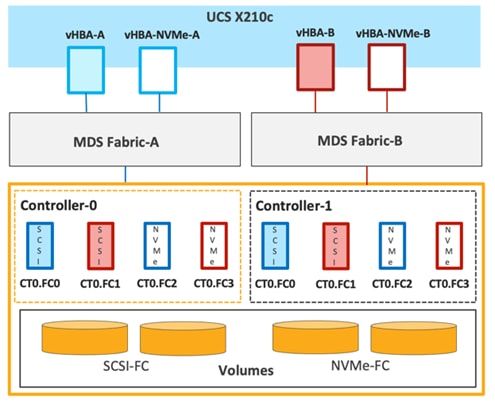
Each port on the Pure FlashArray can be configured as traditional scsi-fc port or as a nvme-fc port to support NVMe end-to-end via fibre channel from the host to storage array. Two ports on each Pure Storage FlashArray controller are configured as SCSI ports and two ports are configured as NVMe ports as shown in Figure 63.
Note: A given FC port on Pure Storage FlashArray can either be configured as FC-SCSI or FC-NVMe port.
In a Cisco UCS server profile, both standard Fibre Channel and FC-NVMe vHBAs can be created. A default Fibre Channel adapter policy named fc-nvme-initiator is preconfigured in Cisco Intersight. This policy contains recommended adapter settings for FC-NVMe. Both Fibre Channel and FC-NVMe vHBAs can exist in a Cisco UCS server profile on a single server.
To support NVMe over Fabric, four vHBAs, two FC-NVME initiators and two Fibre Channel initiators (one on each Fibre Channel fabric), are created for each server profile. Cisco MDS 9132T switches are configured with appropriate zoning to connect the FC-NVMe and Fibre Channel vHBAs to appropriate storage targets. Single-initiator, multiple-target zones are used for both FCP and FC-NVMe. VMware ESXi automatically connects to Pure FlashArray NVMe subsystem and discovers all shared NVMe storage devices that it can reach once the SAN zoning on MDS switches, and the configuration of host/host groups and volumes is completed on the Pure FlashArray.
Deployment Hardware and Software
This chapter contains the following:
· Hardware and Software Revisions
Hardware and Software Revisions
Table 12 lists the hardware and software versions used during solution validation. It is important to note that the validated FlashStack solution explained in this document adheres to Cisco, Pure Storage, and VMware interoperability matrix to determine support for various software and driver versions. Customers should use the same interoperability matrix to determine support for components that are different from the current validated design.
Click the following links for more information:
· Pure Storage Interoperability Matrix. Note, this interoperability list will require a support login form Pure: https://support.purestorage.com/FlashArray/Getting_Started/Compatibility_Matrix
· Pure Storage FlashStack Compatibility Matrix. Note, this interoperability list will require a support login from Pure: https://support.purestorage.com/FlashStack/Product_Information/FlashStack_Compatibility_Matrix
· Cisco UCS Hardware and Software Interoperability Tool: http://www.cisco.com/web/techdoc/ucs/interoperability/matrix/matrix.html
· VMware Compatibility Guide: http://www.vmware.com/resources/compatibility/search.php
Table 12. Hardware and Software Revisions
| Component |
Software |
|
| Network |
Cisco Nexus9000 C93360YC-FX2 |
10.2(3) |
|
|
Cisco MDS 9132T |
9.2(2) |
| Compute |
Cisco UCS Fabric Interconnect 6536 |
9.3(5)I42(2c) |
| Cisco UCS UCSX 9108-100G IFM |
4.2(2c) |
|
| Cisco UCS X210C Compute Nodes |
5.0(2d) |
|
| Cisco UCS VIC 15231 installed on X210c |
5.2(2d) |
|
| Cisco UCS C225 M6 |
4.2(2b) |
|
| Cisco UCS VIC 1467 installed in C225 M6 |
5.2(2b) |
|
| Cisco UCS C245 M6 |
4.2(2b) |
|
| Cisco UCS VIC 1495 installed on C245 M6 |
5.2(2b) |
|
| VMware ESXi |
7.0 U3 |
|
| Cisco VIC ENIC Driver for ESXi |
1.0.42.0 |
|
| Cisco VIC FNIC Driver for ESXi |
5.0.0.34 |
|
| VMware vCenter Appliance |
7.0 U3 |
|
| Cisco Intersight Assist Virtual Appliance |
1.0.9-442 |
|
| Storage |
Pure Storage FlashArray//XL170 |
6.3.3 |
| Pure Storage FlashArray//X50 R3 |
6.3.3 |
|
| Pure Storage VASA Provider |
3.5 |
|
| Pure Storage Plugin |
5.0.0 |
|
In addition to command line interface (CLI) and graphical user interface (GUI) configurations, explained in the deployment guide, all FlashStack components support configurations through automation using Ansible. The FlashStack solution validation team will share automation modules to configure Cisco Nexus, Cisco UCS, Cisco MDS, Pure Storage FlashArray, VMware ESXi, and VMware vCenter. This community-supported GitHub repository is meant to expedite customer adoption of automation by providing them sample configuration playbooks that can be easily developed or integrated into existing customer automation frameworks.
A repository is created in GitHub which Ansible playbooks to configure all the components of FlashStack including:
· Cisco UCS in Intersight Managed Mode
· Cisco Nexus Switches
· Cisco MDS Switches
· Pure FlashArray
· VMware ESXi
· VMware vCenter
The GitHub repository of Ansible playbook is available here: https://github.com/ucs-compute-solutions/FlashStack_IMM_Ansible
Validation
A high-level overview of the FlashStack design validation is provided in this section. Solution validation covers various aspects of the converged infrastructure including compute, virtualization, network, and storage. The test scenarios are divided into four broad categories:
· Data path Validation - 100 Gigabit Ethernet and 32 Gigabit Fibre Channel
· Functional validation – physical and logical setup validation
· Feature verification – feature verification for FlashStack design
· Availability testing – link and device redundancy and high availability testing
· Infrastructure as a code validation – verify automation and orchestration of solution components
The goal of solution validation is to test functional aspects of the design and unless explicitly called out, the performance and scalability is not covered during solution validation. However, limited load is always generated using tools such as FIO, IOMeter, and/or iPerf to help verify test setup. Some of the examples of the types of tests executed include:
· Verification of 100 Gigabit Ethernet and 32 Gigabit Fibre Channel Data path
· Verification of features configured on various FlashStack components
· Powering off and rebooting redundant devices and removing redundant links to verify high availability
· Path MTU verification including both storage and virtual machine traffic
· Failure and recovery of vCenter and ESXi hosts in a cluster
· Failure and recovery of storage access paths across FlashArray controllers, MDS and Nexus switches, and fabric interconnects
· Server Profile migration between compute nodes
· Load generation using IOMeter VMs hosted on FlashStack components and path validation
As part of the validation effort, solution validation team identifies the problems, works with the appropriate development teams to fix the problem, and provides work arounds, as necessary.
The FlashStack solution is a validated approach for deploying Cisco and Pure Storage technologies and products for building shared private and public cloud infrastructure. With the introduction of Cisco X-Series modular platform and 5th Generation Fabric Technology to FlashStack, you can get end-to-end 100 Gigabit Ethernet and 32 Gigabit Fibre Channel. Cisco Intersight with its services, enhances the ability to provide complete visibility and Orchestration across all elements of FlashStack datacenter and modernize the infrastructure and operations of FlashStack datacenter.
Some of the key advantages of integrating Cisco UCS X-Series, 5th Generation Fabric technology and Cisco Intersight into the FlashStack infrastructure are:
· Enables end-to-end 100G Ethernet and 32G Fibre Channel
· Simpler and programmable infrastructure
· Power and cooling innovations and better airflow
· Fabric innovations for heterogeneous compute and memory composability
· Innovative cloud operations providing continuous feature delivery
· Future-ready design built for investment protection
In addition to the Cisco UCS X-Series hardware and software innovations, integration of the Cisco Intersight cloud platform with VMware vCenter and Pure Storage FlashArray delivers monitoring, orchestration, and workload optimization capabilities for the different layers (including virtualization and storage) of the FlashStack infrastructure. The modular nature of the Cisco Intersight platform also provides an easy upgrade path to additional services, such as Virtualization and workload orchestration and optimization.
Paniraja Koppa, Technical Marketing Engineer, Cisco Systems, Inc.
Paniraja Koppa works at Cisco’s Cloud and Compute group with a primary focus on data center and cloud technologies. In his current role, he works on design and development, best practices, optimization, automation and technical content creation of compute and hybrid cloud solutions. Prior to this, he has led QA efforts for 4 new virtual adapter cards for Cisco UCS. He also worked as technical consulting engineer in the Data Center Virtualization space. Paniraja holds a master’s degree in Computer Science. He has presented several papers in International Conferences and speaker at events like Cisco Live US and Europe, Open Infrastructure Summit, and other partner events.
Joe Houghes, Senior Solutions Architect, Pure Storage, Inc.
Joe is a Senior Solutions Architect in the Portfolio Solutions team within Pure Storage, focused on solutions on the FlashStack platform along with automation and integration. He has experience from over 15 years in Information Technology across various customer/vendor organizations with architecture and operations expertise covering compute, networking, storage, virtualization, business continuity and disaster recovery, and cloud computing technologies, plus automation and integration across many applications & vendor platforms.
Acknowledgements
For their support and contribution to the design, validation, and creation of this Cisco Validated Design, the authors would like to thank:
· John George, Technical Marketing Engineer, Cisco Systems, Inc.
· Haseeb Niazi, Principal Technical Marketing Engineer, Cisco Systems, Inc.
· Chris O'Brien, Director, UCS Solutions, Cisco Systems, Inc.
· Rohit Mittal, Product Manager, Cisco Systems, Inc.
· Sreeni Edula, Product Manager, Cisco Systems, Inc.
· Eldho Jacob, Technical Marketing Engineer, Cisco Systems, Inc.
· Craig Waters, Technical Director, Pure Storage, Inc.
This appendix is organized into the following:
· Compute
· Network
· Storage
GitHub repository for solution deployment: https://github.com/ucs-compute-solutions/FlashStack_IMM_Ansible
Cisco Intersight: https://www.intersight.com
Cisco Intersight Managed Mode: https://www.cisco.com/c/en/us/td/docs/unified_computing/Intersight/b_Intersight_Managed_Mode_Configuration_Guide.html
Cisco Unified Computing System: http://www.cisco.com/en/US/products/ps10265/index.html
Cisco UCS 6536 Fabric Interconnects: https://www.cisco.com/c/en/us/products/collateral/servers-unified-computing/ucs6536-fabric-interconnect-ds.html
Cisco Nexus 9000 Series Switches: http://www.cisco.com/c/en/us/products/switches/nexus-9000-series-switches/index.html
Cisco MDS 9132T Switches: https://www.cisco.com/c/en/us/products/collateral/storage-networking/mds-9100-series-multilayer-fabric-switches/datasheet-c78-739613.html
Pure Storage FlashArray//X: https://www.purestorage.com/products/nvme/flasharray-x.html
Pure Storage FlashArray//XL: https://www.purestorage.com/products/nvme/flasharray-xl.html
VMware vCenter Server: http://www.vmware.com/products/vcenter-server/overview.html
VMware vSphere: https://www.vmware.com/products/vsphere
Cisco UCS Hardware Compatibility Matrix: https://ucshcltool.cloudapps.cisco.com/public/
VMware and Cisco Unified Computing System: http://www.vmware.com/resources/compatibility
Pure Storage Interoperability Matrix. Note, this interoperability list will require a support login form Pure: https://support.purestorage.com/FlashArray/Getting_Started/Compatibility_Matrix
Pure Storage FlashStack Compatibility Matrix. Note, this interoperability list will require a support login from Pure: https://support.purestorage.com/FlashStack/Product_Information/FlashStack_Compatibility_Matrix
For comments and suggestions about this guide and related guides, join the discussion on Cisco Community at https://cs.co/en-cvds.
CVD Program
ALL DESIGNS, SPECIFICATIONS, STATEMENTS, INFORMATION, AND RECOMMENDATIONS (COLLECTIVELY, "DESIGNS") IN THIS MANUAL ARE PRESENTED "AS IS," WITH ALL FAULTS. CISCO AND ITS SUPPLIERS DISCLAIM ALL WARRANTIES, INCLUDING, WITHOUT LIMITATION, THE WARRANTY OF MERCHANTABILITY, FITNESS FOR A PARTICULAR PURPOSE AND NONINFRINGEMENT OR ARISING FROM A COURSE OF DEALING, USAGE, OR TRADE PRACTICE. IN NO EVENT SHALL CISCO OR ITS SUPPLIERS BE LIABLE FOR ANY INDIRECT, SPECIAL, CONSEQUENTIAL, OR INCIDENTAL DAMAGES, INCLUDING, WITHOUT LIMITATION, LOST PROFITS OR LOSS OR DAMAGE TO DATA ARISING OUT OF THE USE OR INABILITY TO USE THE DESIGNS, EVEN IF CISCO OR ITS SUPPLIERS HAVE BEEN ADVISED OF THE POSSIBILITY OF SUCH DAMAGES.
THE DESIGNS ARE SUBJECT TO CHANGE WITHOUT NOTICE. USERS ARE SOLELY RESPONSIBLE FOR THEIR APPLICATION OF THE DESIGNS. THE DESIGNS DO NOT CONSTITUTE THE TECHNICAL OR OTHER PROFESSIONAL ADVICE OF CISCO, ITS SUPPLIERS OR PARTNERS. USERS SHOULD CONSULT THEIR OWN TECHNICAL ADVISORS BEFORE IMPLEMENTING THE DESIGNS. RESULTS MAY VARY DEPENDING ON FACTORS NOT TESTED BY CISCO.
CCDE, CCENT, Cisco Eos, Cisco Lumin, Cisco Nexus, Cisco StadiumVision, Cisco TelePresence, Cisco WebEx, the Cisco logo, DCE, and Welcome to the Human Network are trademarks; Changing the Way We Work, Live, Play, and Learn and Cisco Store are service marks; and Access Registrar, Aironet, AsyncOS, Bringing the Meeting To You, Catalyst, CCDA, CCDP, CCIE, CCIP, CCNA, CCNP, CCSP, CCVP, Cisco, the Cisco Certified Internetwork Expert logo, Cisco IOS, Cisco Press, Cisco Systems, Cisco Systems Capital, the Cisco Systems logo, Cisco Unified Computing System (Cisco UCS), Cisco UCS B-Series Blade Servers, Cisco UCS C-Series Rack Servers, Cisco UCS S-Series Storage Servers, Cisco UCS Manager, Cisco UCS Management Software, Cisco Unified Fabric, Cisco Application Centric Infrastructure, Cisco Nexus 9000 Series, Cisco Nexus 7000 Series. Cisco Prime Data Center Network Manager, Cisco NX-OS Software, Cisco MDS Series, Cisco Unity, Collaboration Without Limitation, EtherFast, EtherSwitch, Event Center, Fast Step, Follow Me Browsing, FormShare, GigaDrive, HomeLink, Internet Quotient, IOS, iPhone, iQuick Study, LightStream, Linksys, MediaTone, MeetingPlace, MeetingPlace Chime Sound, MGX, Networkers, Networking Academy, Network Registrar, PCNow, PIX, PowerPanels, ProConnect, ScriptShare, SenderBase, SMARTnet, Spectrum Expert, StackWise, The Fastest Way to Increase Your Internet Quotient, TransPath, WebEx, and the WebEx logo are registered trademarks of Cisco Systems, Inc. and/or its affiliates in the United States and certain other countries. (LDW_P1)
All other trademarks mentioned in this document or website are the property of their respective owners. The use of the word partner does not imply a partnership relationship between Cisco and any other company. (0809R)