Cisco Unified Edge and Red Hat Enterprise Linux Deployment Guide
Available Languages
Bias-Free Language
The documentation set for this product strives to use bias-free language. For the purposes of this documentation set, bias-free is defined as language that does not imply discrimination based on age, disability, gender, racial identity, ethnic identity, sexual orientation, socioeconomic status, and intersectionality. Exceptions may be present in the documentation due to language that is hardcoded in the user interfaces of the product software, language used based on RFP documentation, or language that is used by a referenced third-party product. Learn more about how Cisco is using Inclusive Language.
- US/Canada 800-553-2447
- Worldwide Support Phone Numbers
- All Tools
 Feedback
 Feedback
In partnership with:
![]()
Executive Summary
We’re at a critical inflection point. The edge has emerged as the place where the physical and digital worlds meet, demanding real-time processing and analysis of data to deliver informed decisions, improved experiences, and increased productivity. However, legacy infrastructure wasn’t built for the AI era and can’t keep up with the scale, speed, and intelligence required by AI-driven operations. While much of the model training happens in the data center, the shift of test-time inference to the edge makes it the new frontier for enterprise AI.
Deploying AI at the edge remains complicated and demanding. Interoperability, security, cost, and rigid deployment models are all potential performance and productivity blockers. The increasing demand for AI and digitization at the edge necessitates a full system rethink, as evolving business needs and the sheer scale of highly distributed edge environments and modern AI workloads create a beyond-human complexity nightmare. We need something more than just more boxes; we need a brand-new edge infrastructure and operations vision.
Cisco Unified Edge is an AI-ready system that redefines computing at the edge by converging compute, networking, storage, and security. Designed from the edge up, for the next decade, the modular design is future-ready, energy-efficient, and easy-to-service, and can be tailored to support today’s workloads and use cases, while remaining adaptable to the rapidly evolving AI landscape. Seamless integration with third-party technologies and validated solutions for industry-specific needs ensure both compatibility and optimized performance.
Delivering breakthrough operational simplicity at scale, this software-defined system features centralized cloud management, zero-touch deployment, curated blueprints, and automated orchestration. These capabilities enable high scalability with minimal complexity. End-to-end observability with real-time analytics accelerates error detection and correction, helping minimize service outages. Security is designed-in, with integrated physical and digital safeguards to protect applications and data at the edge while multi-layered security capabilities protect infrastructure, applications, and AI models.
Benefits
The key benefits are:
● Future-ready performance: Adaptable to meet today and tomorrow's edge workload demands with ease, stopping the rip-and-replace cycle with a fully integrated, modular edge environment built for the next decade. Deploy applications and infrastructure faster and profit sooner with proven solutions that are tested and certified for vertical-specific workloads and use cases, ensuring compatibility and performance.
● Full-scale simplicity: Onboard quickly and with ease without the need for highly skilled IT expertise or on-site visits. Whether deploying ten systems or ten thousand, zero-touch provisioning, curated blueprints and automation ensure consistent, effortless rollout. A consistent operating model from core to edge makes it easy to scale, upgrade, and support your infrastructure.
● Designed-in security: Prevent tampering at the edge with robust physical and digital protection. Proven policy-based templates eliminate configuration drift across sites. Embedded, zero-trust security capabilities ensure unmatched protection for your edge infrastructure, data, and AI models.
Red Hat, the leading provider of enterprise open-source solutions, offers a comprehensive and integrated portfolio of technologies designed to modernize enterprise IT operations, accelerate innovation, and reduce complexity across hybrid cloud, data center, and edge environments. This technical design guide explores how Red Hat's enterprise platform can be effectively deployed on Cisco Unified Edge System (Cisco UCS XE9305) to deliver scalable, secure, and mission-critical solutions.
Red Hat's enterprise-grade architecture aligns seamlessly with Cisco Unified Edge infrastructure model, enabling:
● Rapid provisioning and scaling of containerized and virtualized workloads
● Unified management and automation across compute, storage, and networking
● Optimized performance for cloud-native applications, traditional workloads, and AI/ML inference
● Enterprise support and certified interoperability for production environments
Together, Red Hat and Cisco Unified Edge empower enterprises to build resilient, future-ready platforms that support digital transformation, edge computing, and AI innovation.
The design of this solution is driven by its ability to evolve and incorporate both technology and product innovations in the areas of management, computing, storage, and networking to be used at the edge. To help organizations with their digital transformation and application modernization practices, Cisco and Red Hat have partnered to produce this Cisco Validated Design (CVD) for the joint Unified Edge and Red Hat edge solutions minimizing risks by validating the integrated architecture to ensure compatibility between various components. The solution also addresses pain points by providing documented design guidance, deployment guidance, and support that can be used in various stages (planning, designing, and implementation) of a business project targeting Edge deployments. The solution is part of Cisco’s Blueprint and Fleet management enhancement of Intersight and will be delivered as Infrastructure as Code (IaC) to further eliminate error-prone manual tasks, allowing quicker and more consistent solution deployments.
Solution Overview
This chapter contains the following:
● Audience
The deployment options use pre-designed, integrated, and validated architectures for the edge that combine Cisco Unified Edge, with servers, network, and security, and Red Hat products into a single, flexible architecture. The solutions are designed to meet a broad range of deployment options, while maintaining cost-effectiveness and flexibility to support a wide variety of workloads.
The range of deployment options goes from a single node Linux host to run a small number of virtual machines or containers up to a multi-node Kubernetes cluster with an integrated software defined storage option to provide full high-availability and scalability for a larger number of virtual machines, container-based applications, AI workloads and mission critical control units.
The following design and deployment aspects of this edge solution are explained in this document:
● Cisco Unified Edge
● Single node RHEL host with Podman and KVM
● Deployment options for virtual machines and container-based workloads
● Integration into edge networks
The intended audience of this document includes but is not limited to IT architects, sales engineers, field consultants, professional services, IT managers, partner engineering, and those who want to take advantage of an infrastructure built to deliver efficiency and enable innovation.
This document provides design guidance around incorporating the Cisco Intersight—managed Cisco Unified Edge platform to run Red Hat edge solutions. The document introduces various design elements and covers various considerations and best practices for a successful deployment.
The components are integrated and validated, and where possible, Intersight Blueprints will explain the installation and configuration of the entire stack so that you can deploy your solution quickly and economically, while eliminating many of the risks associated with researching, designing, building, and deploying similar solutions from the ground up.
The Cisco Unified Edge with Red Hat edge solution offers the following key benefits:
● Standardized architecture for quick, repeatable, error-free deployments of workload domains
● Automated life cycle management to keep all the system components up to date
● Simplified cloud-based management of various components
● Hybrid-cloud-ready, policy-driven modular design
● Highly available, flexible, and scalable architecture
● Cooperative support model and Cisco Solution Support
● Easy to deploy, consume, and manage design that aligns with Cisco and Red Hat best practices and compatibility requirements
● Support for component monitoring, solution automation and orchestration, and workload optimization
● Validated integration into Meraki and Catalyst network domains.
Like all other Cisco Validated solution designs, Cisco Unified Edge with Red Hat is configurable according to demand and usage. You can purchase the exact infrastructure needed for your current application requirements. You can scale-up by adding more resources to the solution or scale-out by adding more Unified Edge instances.
Technology Overview
This chapter contains the following:
● Cisco Unified Edge Management
Cisco Unified Edge with Red Hat is built using compute, network, and storage components integrated in the Unified Edge platform. The solution consists of the following core elements:
● Cisco Unified Edge System (Cisco UCS XE9305)
● Red Hat Enterprise Linux (RHEL) with Podman and KVM
One of the key benefits of Cisco Unified Edge is its ability to maintain consistency during scale where required. Each of the components offers platform and resource options to scale the infrastructure up or down while supporting the same features and functionality that are required under the configuration and connectivity best practices. The key features and highlights of the components are explained in the following sections.
Cisco Unified Edge is part of the Cisco Unified Computing System (Cisco UCS) family designed from the ground up to address deployments where traditional data center servers are not a perfect fit. With its new physical design and the new components, like other Cisco UCS platforms, Cisco Unified Edge uses Cisco Intersight as its management platform.
The Cisco Intersight platform is a Software-as-a-Service (SaaS) infrastructure lifecycle management platform that delivers simplified configuration, deployment, maintenance, and support. The Cisco Intersight platform is designed to be modular, so you can adopt services based on your individual requirements. The platform significantly simplifies IT operations by bridging applications with infrastructure, providing visibility and management from bare-metal servers and hypervisors to serverless applications, thereby reducing costs and mitigating risk. This unified SaaS platform uses an Open API design that natively integrates with third-party platforms and tools.
The capabilities of Cisco Intersight were extended with a Fleet Management option to automate and accelerate deployment of Cisco UCS and Unified Edge systems at remote locations at scale. With the new Fleet Management, it is possible to define location profiles and Blueprints to allow zero-touch provisioning of the hardware and operating systems as soon as the new hardware is claimed in Intersight.
While the Cisco UCS XE9305 is a programmable infrastructure, the Cisco Intersight API is how management tools program it. This enables the tools to help guarantee consistent, error-free, policy-based alignment of server personalities with workloads. Through automation, transforming the server and networking components of your infrastructure into a complete solution is fast and error-free because programmability eliminates the error-prone manual configuration of servers and integration into solutions. Server, network, and storage administrators are now free to focus on strategic initiatives rather than spending their time performing tedious tasks.
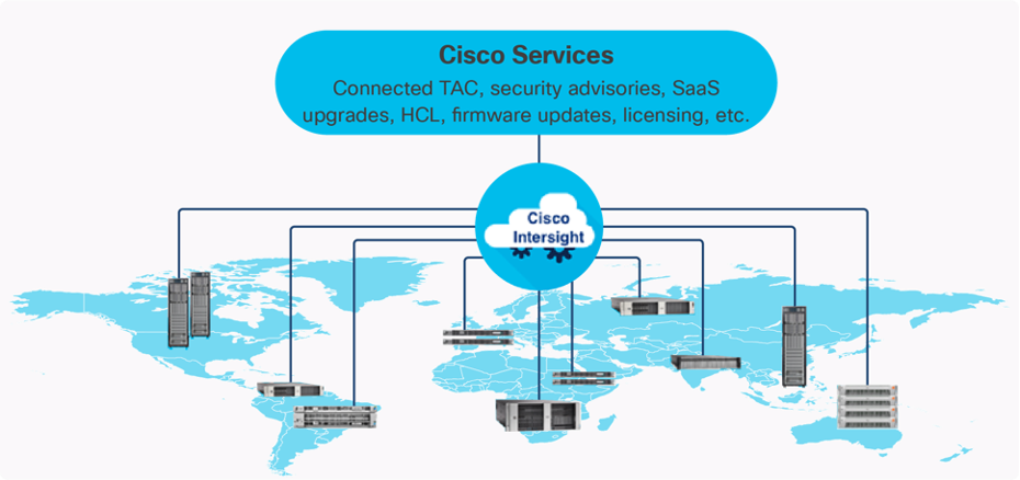
The main benefits of Cisco Intersight infrastructure services are as follows:
● Simplify daily operations by automating many daily manual tasks
● Combine the convenience of a SaaS platform with the capability to connect from anywhere and manage infrastructure through a browser or mobile app
● Stay ahead of problems and accelerate trouble resolution through advanced support capabilities
● Gain global visibility of infrastructure health and status along with advanced management and support capabilities
Licensing Requirements
The Cisco Intersight platform uses a subscription-based license with multiple tiers. You can purchase a subscription duration of one, three, or five years and choose the required Cisco UCS server volume tier for the selected subscription duration. Each Cisco endpoint automatically includes a Cisco Intersight Base license at no additional cost when you access the Cisco Intersight portal and claim a device. You can purchase any of the following higher-tier Cisco Intersight licenses using the Cisco ordering tool:
● Cisco Intersight Infrastructure Services Essentials: The Essentials license tier offers server management with global health monitoring, inventory, proactive support through Cisco TAC integration, multi-factor authentication, along with SDK and API access.
● Cisco Intersight Infrastructure Services Advantage: The Advantage license tier offers advanced server management with extended visibility, ecosystem integration, and automation of Cisco and third-party hardware and software, along with multi-domain solutions.
Servers in the Cisco Intersight managed mode require at least the Essentials license. For detailed information about the features provided in the various licensing tiers, see https://intersight.com/help/getting_started#licensing_requirements.
DevOps and Tool Support
The Cisco Intersight API is of great benefit to developers and administrators who want to treat physical infrastructure the way they treat other application services, using processes that automatically provision or change IT resources. Similarly, your IT staff needs to provision, configure, and monitor physical and virtual resources; automate routine activities; and rapidly isolate and resolve problems. The Cisco Intersight API integrates with DevOps management tools and processes and enables you to easily adopt DevOps methodologies.
The Cisco Unified Edge Modular System is designed to take the current generation of the Cisco UCS platform to the next level with its future-ready design and cloud-based management. Decoupling and moving the platform management to the cloud allows Cisco UCS to respond to customer feature and scalability requirements in a much faster and more efficient manner. Cisco Unified Edge’s state-of-the-art hardware simplifies the edge design by providing flexible server options.
Cisco UCS XE9305 Chassis
The Cisco Unified Edge chassis is engineered to be adaptable and flexible. As seen in Figure 3, the Cisco Unified Edge XE9305 chassis has a power-distribution backplane. This innovative design provides fewer obstructions for better airflow.
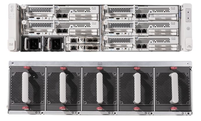
The Cisco UCS XE9305 3-Rack-Unit (3RU) chassis has five flexible slots. These slots can house a combination of compute nodes and network nodes (future). At the bottom of the chassis are two edge Chassis Management Controller (eCMC) that connect the chassis to upstream network. On the left of the eCMCs, two Power Supply Units (PSUs) provide power to the chassis with N+N redundancy. At the back of the chassis, five efficient, 80mm, dual counter-rotating fans deliver industry-leading airflow and power efficiency, and optimized thermal algorithms enable different cooling modes to best support the customer’s environment.
Cisco Unified Edge – Edge Chassis Management Controller
The Cisco Edge Chassis Management Controller (eCMC) provides a single point for connectivity and management for the entire Cisco Unified Edge system.
The Cisco Unified Edge eCMC provides the management and communication backbone for the Cisco UCS XE130c M8 compute nodes in the Cisco UCS XE9305 Series Chassis. All nodes attached to the Cisco Unified Edge eCMC become part of a single, highly available management domain.
The Cisco Unified Edge eCMC utilized in the current design includes one Ethernet port for management, two Ethernet ports for data traffic, and one Ethernet port to each slot in the chassis.
Cisco UCS XE130c M8 Compute Node
The Cisco UCS XE9305 Chassis is designed to host up to five Cisco UCS XE130c Compute Nodes. The hardware details of the Cisco UCS XE130c M8 Compute Nodes are shown in Figure 4:
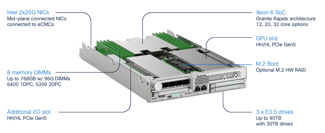
The Cisco UCS XE130c M8 features:
● CPU: One 6th Gen Intel Xeon SoC Processor with 12, 20, or 32 cores.
● Memory: Up to 8 x 96 GB DDR5-6400 DIMMs for a maximum of 768 GB of main memory.
● Disk storage: Up to 4 E3.s NVMe drives (with storage optimized SKU) and one M.2 RAID controller with two M.2 memory cards with RAID 1 mirroring.
● LAN on Mainboard (LoM): Intel E825 NIC is integrated in the Xeon SoC Processor with two 25 Gbps ports on the Mid-plane and two 1/10 Gbps RJ45 ports on the front of each Compute Node.
● GPU: Dedicated PCIe Gen-5 slot for one HH/HL GPU with up to 75 Watt.
● Security: The server supports an optional Trusted Platform Module (TPM).
This Cisco Unified Edge Solution with Red Hat was tested using both Cisco Catalyst and Cisco Meraki network domains.
Graphics Processing Units or GPUs are specialized processors designed to render images, animation and video for computer displays. They perform these tasks by running many operations simultaneously. While the number and kinds of operations they can do are limited, GPUs can run many thousand operations in parallel making this massive parallelism extremely useful for deep learning applications. Deep learning relies on GPU acceleration for both training and inference, and GPU accelerated data centers deliver breakthrough performance with fewer servers at a lower cost. This CVD details the following NVIDIA GPUs:
NVIDIA L4 Tensor Core GPU
The NVIDIA L4 Tensor Core, powered by the Ada Lovelace architecture, is a versatile and energy-efficient accelerator designed for workloads such as AI, video processing, graphics, and virtualization. Its low-profile form factor and high performance make it suitable for deployment across edge, data center, and cloud environments.
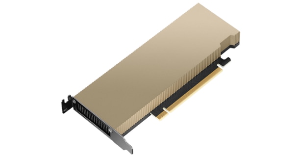
The NVIDIA L4 card is a single-slot PCI Express Gen4 card. It uses a passive heat sink for cooling, which requires system airflow to operate the card properly within its thermal limits. The NVIDIA L4 PCIe operates unconstrained up to its maximum thermal design power (TDP) level of 72 W to accelerate applications that require the fastest computational speed and highest data throughput at the edge.
The software layer of the NVIDIA AI platform, NVIDIA AI Enterprise, accelerates the data science pipeline and streamlines the development and deployment of production AI including generative AI, computer vision, speech AI and more. With over 50 frameworks, pre-trained models, and development tools, NVIDIA AI Enterprise is designed to accelerate enterprises to the leading edge of AI while simplifying AI to make it accessible to every enterprise.
Red Hat Enterprise Linux (RHEL)
Red Hat Enterprise Linux (RHEL) is the industry-leading enterprise Linux platform, providing a stable, secure, and high-performance foundation for running both containerized and virtualized workloads at the edge. RHEL 9 includes built-in support for Podman, a daemonless container engine for managing OCI containers and images, and KVM/libvirt, which enables full hardware-accelerated virtual machine hosting. Together, Podman and KVM allow organizations to run a broad range of workloads — from lightweight containers to full guest operating systems — on a single, resource-efficient RHEL host. RHEL's enterprise support, SELinux-enforced security model, and subscription-based lifecycle management make it well-suited for production edge deployments where stability, compliance, and long-term supportability are critical requirements.
AI Inferencing at the Edge Landscape
AI inferencing at the edge enables real-time decision-making by processing data locally on devices, gateways, or micro data centers instead of relying solely on centralized cloud infrastructure. This decentralized approach is vital in latency-sensitive, bandwidth-constrained, or privacy-focused environments where immediate action is required, and network connectivity may be intermittent.
Key Use Cases and Benefits
● Industrial Automation and Predictive Maintenance - Enables real-time predictive maintenance by analyzing sensor data locally, reducing downtime and maintenance costs.
● Retail Intelligence and Smart Environments - Uses smart cameras and AI analytics at the edge to optimize customer experience, shelf layouts, and inventory management.
● Healthcare Diagnostics - Processes patient vitals and imaging data on edge devices for instant diagnostics while maintaining data privacy.
● Security and Surveillance - Performs on-site AI-based threat detection, facial recognition, and anomaly monitoring with minimal latency.
● Smart Agriculture - Employs drones and sensors running AI models to assess crop health, detect pests, and optimize irrigation in real time.
Cisco Unified Edge with RHEL, Podman, and KVM Deployment
This chapter contains the following:
● Configure Cisco Unified Edge Using Intersight
● Install and Configure RHEL Using Cisco Intersight vKVM / Tunneled KVM
● Install and Configure SNO Using CLI and YAMLs
Before deploying Red Hat Enterprise Linux (RHEL) with Podman and KVM on Cisco Unified Edge, you must ensure that essential infrastructure services are available and properly configured. These services provide the foundation for successful RHEL host deployment and operation at both the Unified Edge and workload levels. You can deploy these services at edge locations or leverage existing services in the regional data center.
Required Infrastructure Services:
● Workstation - A system with internet access to both Cisco Intersight and Red Hat Hybrid Cloud Console, along with required deployment tools
● DHCP Server - For automatic IP address assignment during installation
● NTP Server - To ensure time synchronization across the RHEL host and connected infrastructure
● DNS Servers - For name resolution and host service discovery
The validated solution includes a Cisco UCS XE9305 chassis with up to 5 Cisco UCS XE130c M8 compute nodes.
● Cisco UCS XE9305 chassis is connected to a pair of Meraki MS (C9300L-24UXG-4X) switches. The first eCMC connects both of its 10 GbE uplinks via a port-channel to the first switch, while the second eCMC connects its bundled uplinks entirely to the second switch.
● Each Cisco UCSXE-eCMC-G1’s management port is connected to a separate Meraki MS switch.
● Two 10GbE links provide connectivity between two Meraki MS switches. Both links are bundled as a port-channel for increased bandwidth and link redundancy.
● Each switch is connected to the same Meraki MX using a 1GbE link.
● The Meraki MX68W uses dedicated Internet/WAN ports to connect to ISPs for Internet connectivity
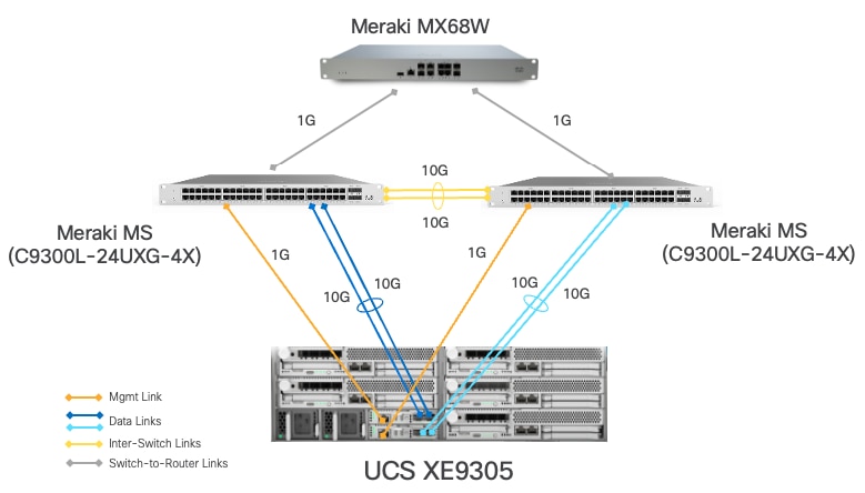
Table 1. VLAN and Network Usage
| VLAN Name |
VLAN ID |
IP Subnet |
Subnet Mask |
Default Gateway |
MTU |
| OOB-MGMT-VLAN |
1315 |
10.131.5.0 |
255.255.255.0 |
10.131.5.1 |
1500 |
| IB-MGMT-VLAN |
1316 |
10.131.6.0 |
255.255.255.0 |
10.131.6.1 |
1500 |
| ACCESS-VLAN |
1317 |
10.131.7.0 |
255.255.255.0 |
10.131.7.1 |
1500 |
| WORKLOAD-VLAN |
1318 |
10.131.8.0 |
255.255.255.0 |
10.131.8.1 |
1500 |
Some of the key highlights of VLAN usage in the validated design are shown below:
● VLAN 1315 allows you to manage and access out-of-band management interfaces of various devices and is brought into the infrastructure to allow IMC access to the Unified Edge eCMC.
● VLAN 1316 serves as the in-band management VLAN which is required to use vMedia policy and CIMC-Mounted ISO images inside Unified Edge. It is also the Native VLAN to allow network traffic to the next-hop switch without VLAN tagging.
● VLAN 1317 is used to access the RHEL host.
● VLAN 1318 is added to provide an additional interface that connects virtual machines to the dedicated or isolated network.
Configure Cisco Unified Edge Using Intersight
The deployment of Cisco UCS XE9305 Unified Edge devices through Intersight uses a template-based approach that streamlines configuration management across both chassis and compute resources. Follow these stages to complete the configuration:
● Claim the Unified Edge Device: Register the Cisco UCS XE9305 to Cisco Intersight using the claim code to enable cloud-based management and monitoring.
● Build the Unified Edge Profile Template: Create the necessary Unified Edge policies first and associate them with a Unified Edge Profile Template that defines chassis-level configurations.
● Apply Unified Edge Configuration: Generate a Unified Edge Profile from the template and bind it to the target Cisco UCS XE9305.
● Create Server Profile Template: Create the necessary Server Policies first, then build a Server Profile Template that references these policies to define comprehensive compute node configurations.
● Provision Servers: Instantiate Server Profiles from the template and associate them with individual Cisco UCS XE130c M8 servers.
● Activate Tunnel KVM Access: Enable the Tunnel KVM capability to allow secure remote console access to servers directly from the Intersight interface.
Claim a Cisco Unified Edge UCS XE9305 Chassis in Cisco Intersight
After getting out-of-band management IP addresses, the Cisco Unified Edge UCS XE9305 device needs to be claimed in a new or existing Cisco Intersight account. When a UCS XE9305 is successfully added to Cisco Intersight, all future configuration steps are completed in the Cisco Intersight portal.
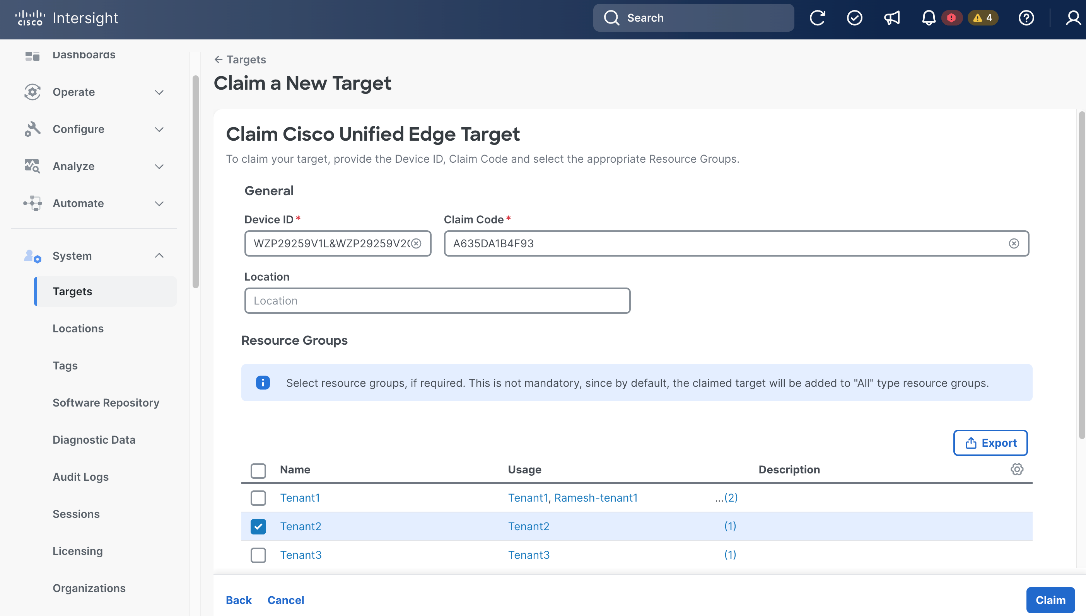
Procedure 1. Claim Unified Edge in Cisco Intersight
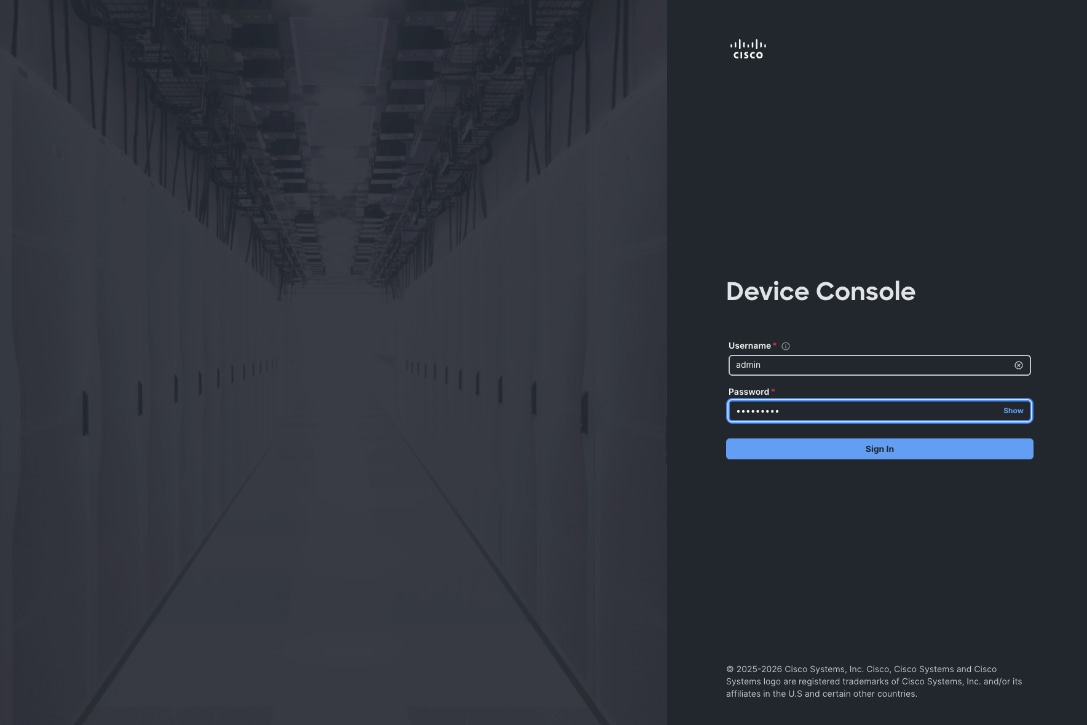
Step 1. Use the management IP address of one Unified Edge eCMC to access the device from a web browser and log in with the previously configured admin password.
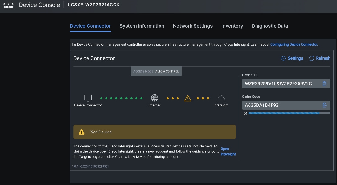
Step 2. Under DEVICE CONNECTOR, the current device status will show Not claimed. Note or copy the Device ID and Claim Code information for claiming the device in Cisco Intersight.
Step 3. Log in to Cisco Intersight.
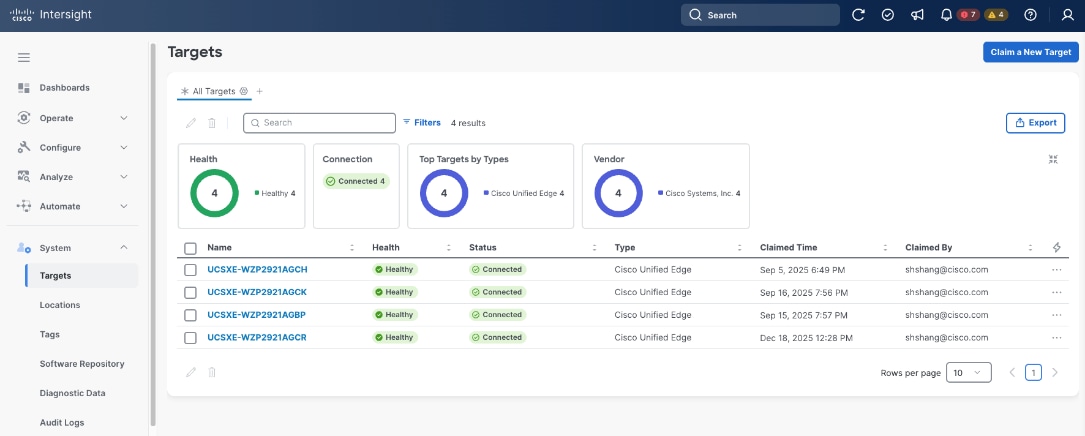
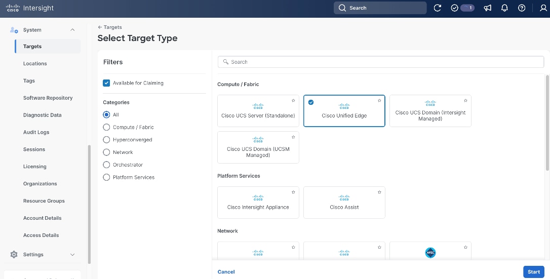
Step 4. Go to System > Targets, then click Claim a New Target.
Step 5. Select Cisco Unified Edge and click Start.
Step 6. Copy and paste the Device ID and Claim Code from the previous step to Intersight.
Step 7. Select the correct resource group and click Claim.
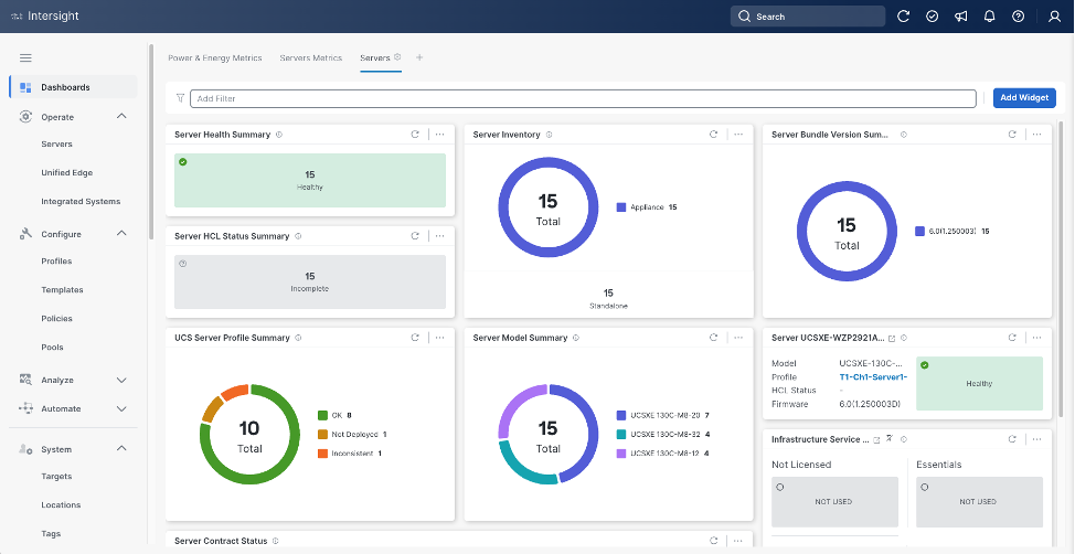
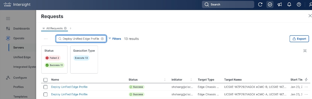
With a successful device claim, Cisco Unified Edge device (UCSXE-WZP2921AGCK), appears as a target in Cisco Intersight:
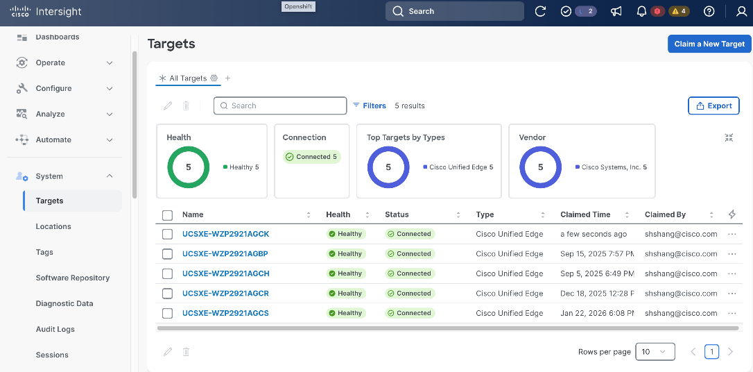
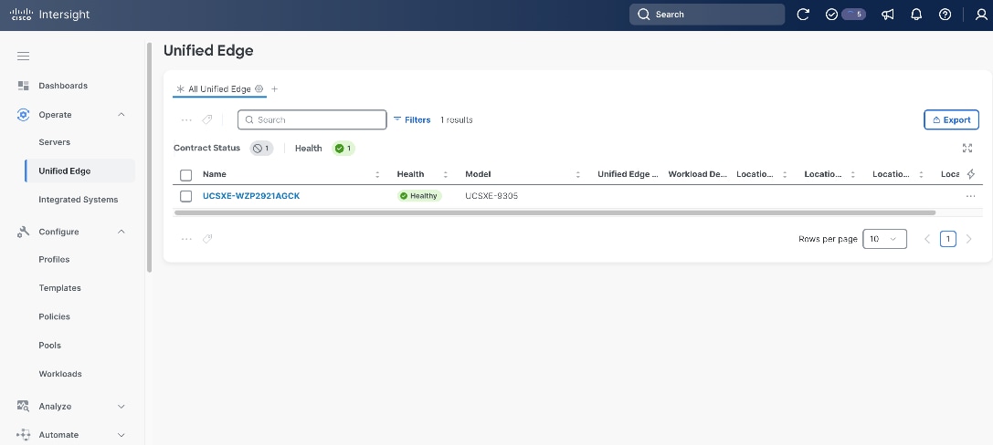
Step 8. Go to Operate > Unified Edge, the claimed Unified Edge device should show up. Verify the Health status is Healthy.
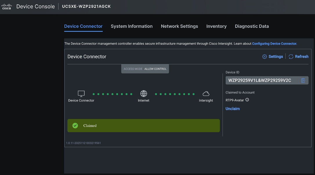
Step 9. Log back in to Device Console using one of the eCMC management IP addresses, then click Refresh. The Device Connector status is changed to Claimed.
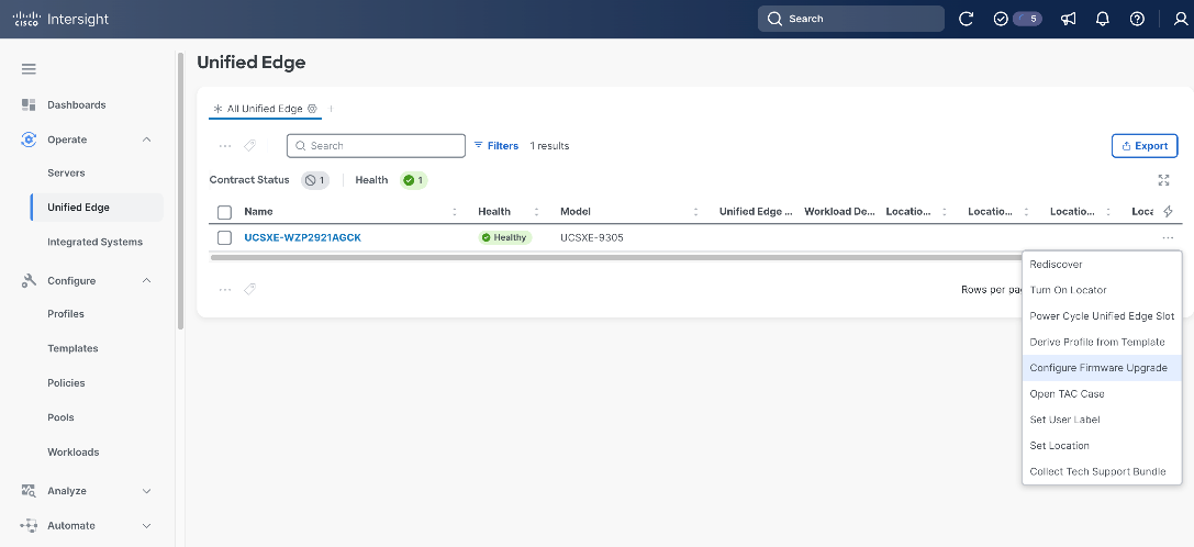
Procedure 2. Upgrade Unified Edge Firmware (Optional)
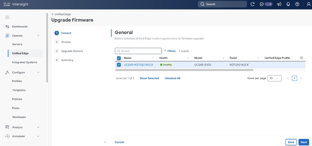
Step 1. Go to Operate > Unified Edge, select the UCS XE9305 device, click the ellipses (…) at the end of the row. From the drop-down list, select Configure Firmware Upgrade.
Step 2. On the General page, click Next.
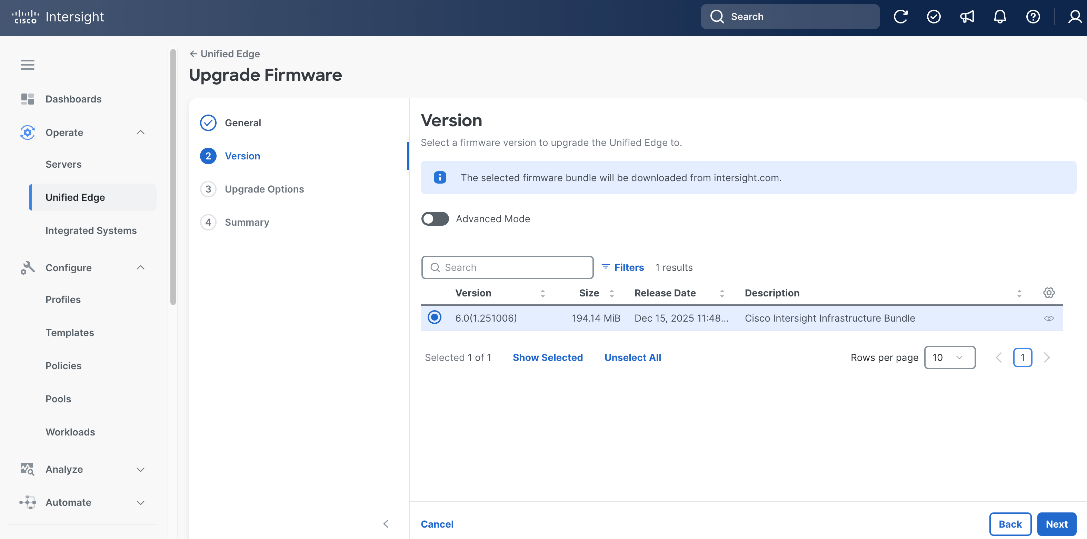
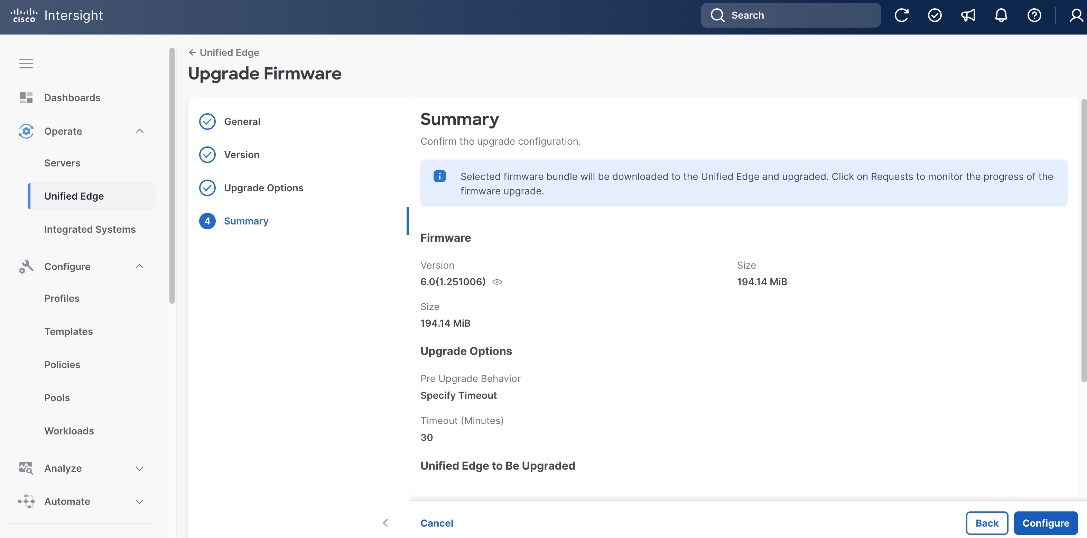
Step 3. On the Version page, select the target bundle release, which is 6.0(1.251006) in this example.
Step 4. Click Next.
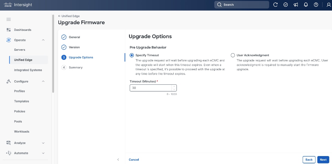
Step 5. On the Upgrade Options page, leave everything at their default settings.
Step 6. Click Next.
Step 7. On the Summary page, click Configure.
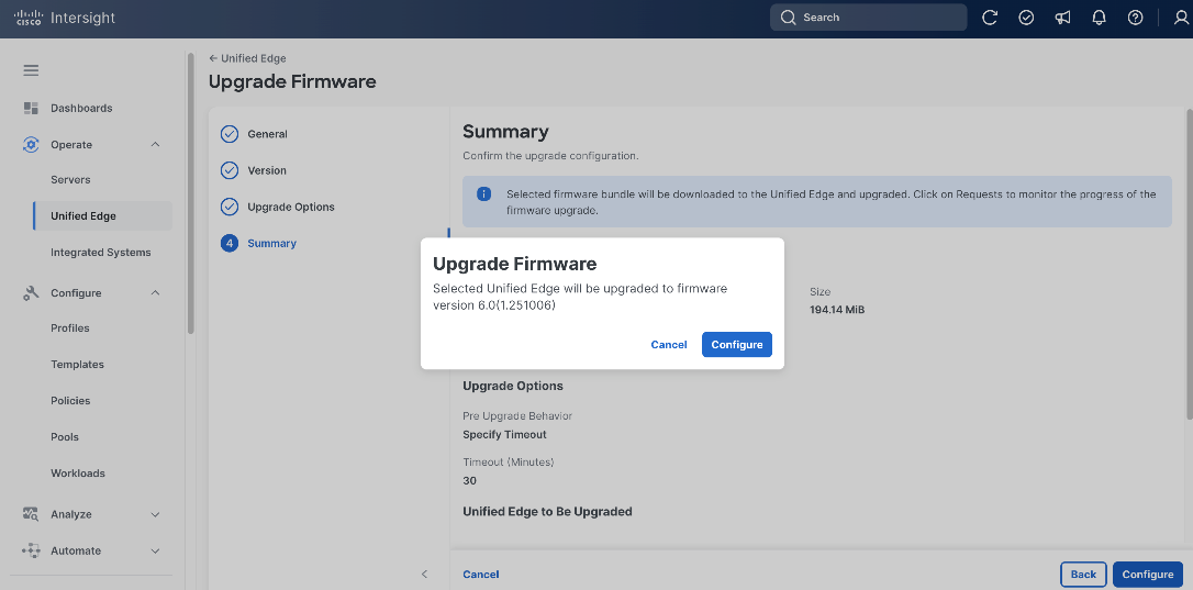
Step 8. In the pop-up window, click Configure.
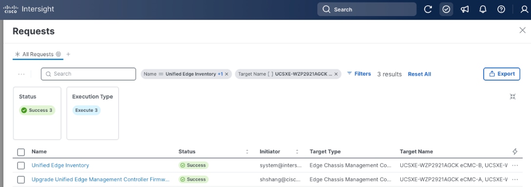
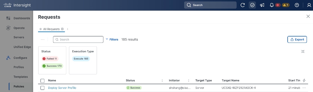
Step 9. Click the checkmark icon at upper-right corner to monitor the status of firmware upgrade request. It will take a while for Upgrade Unified Edge Management Controller Firmware and Unified Edge Inventory requests to reach Success status.
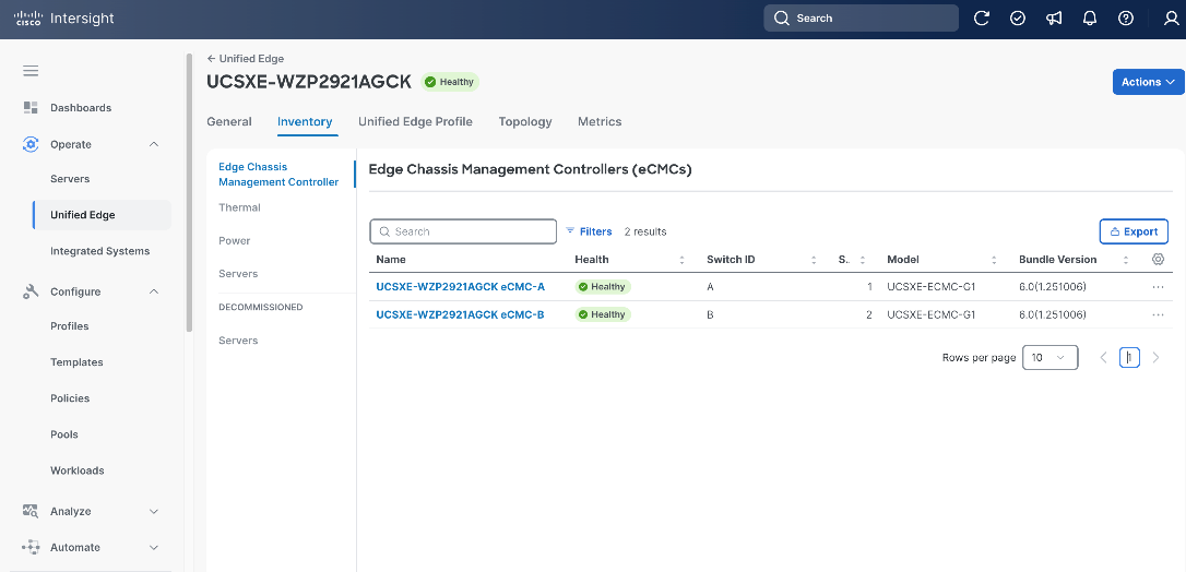
Step 10. When firmware upgrade is complete, go to Operate > Unified Edge, click the newly added UCS XE9305 device.
Step 11. Go to the Inventory tab, click Edge Chassis Management Controller. Verify both eCMC controllers are in Healthy status, and the Bundle Version column shows the right release.
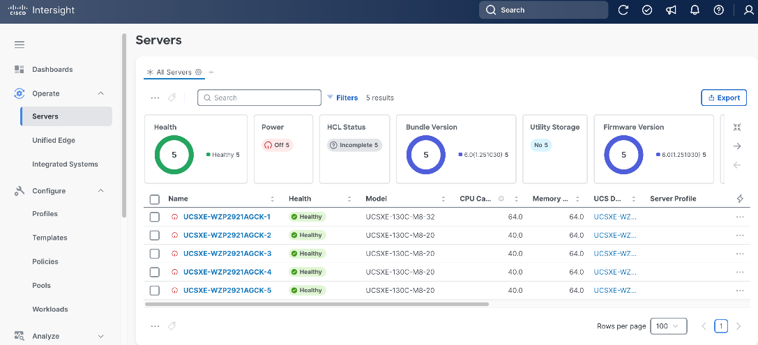
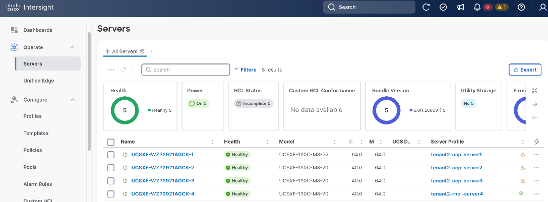
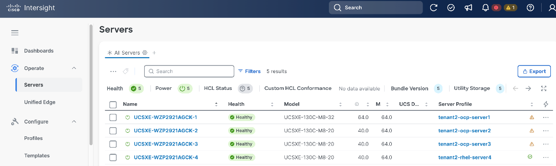
Step 12. Go to Operate > Servers, verify the UCS XE130c M8 servers on the newly added UCS XE9305 device are discovered.
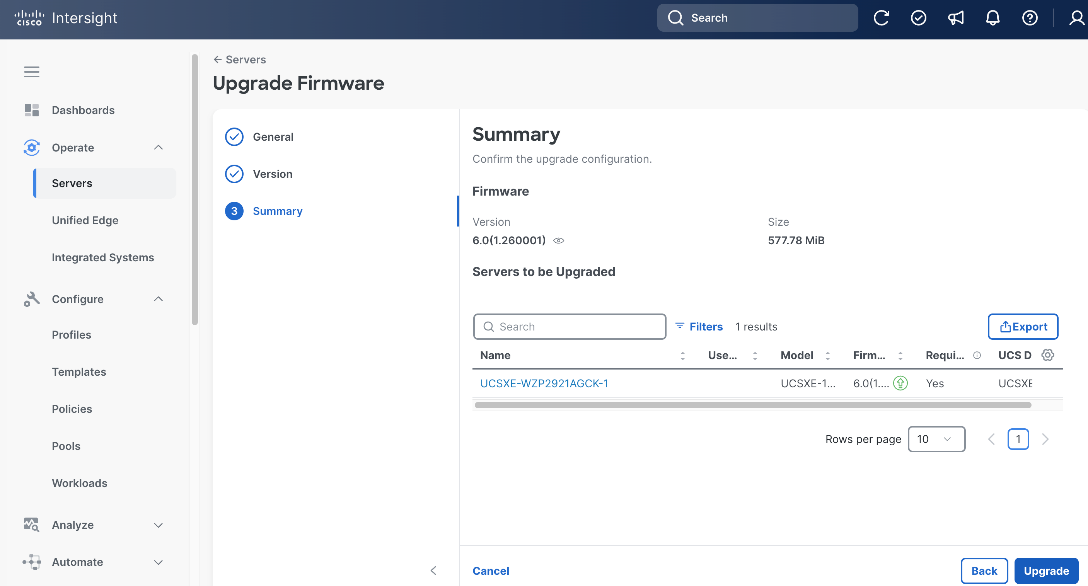
Procedure 3. Upgrade Server Firmware (Optional)
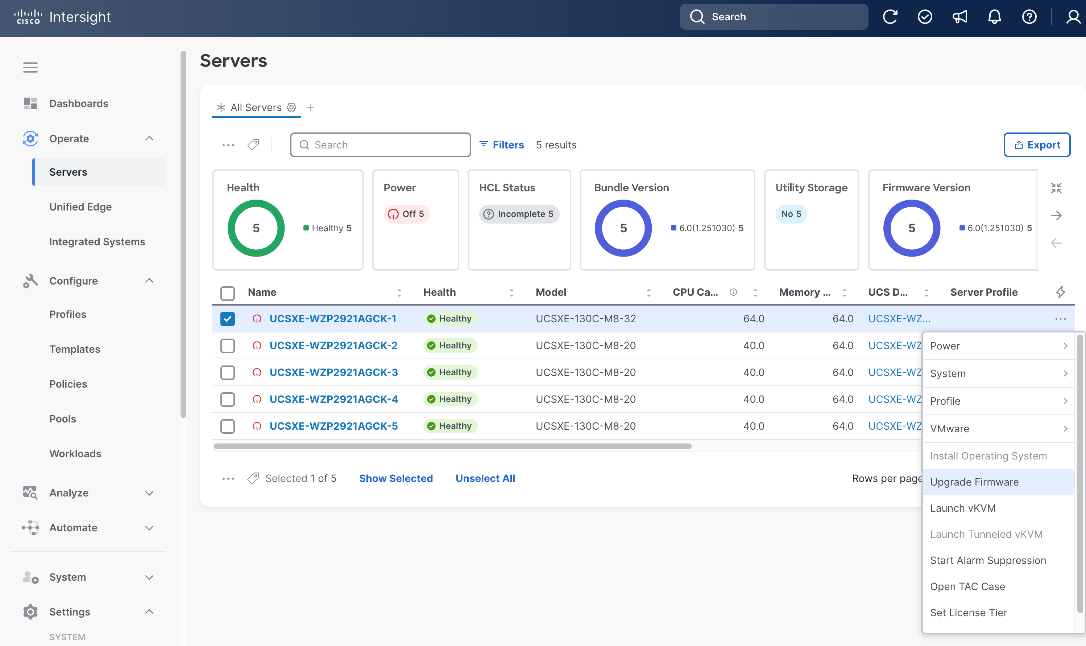
Step 1. Go to Operate > Servers, select a UCS XE130c M8 server, click the ellipses (…) at the end of the row. From the drop-down list, select Upgrade Firmware.
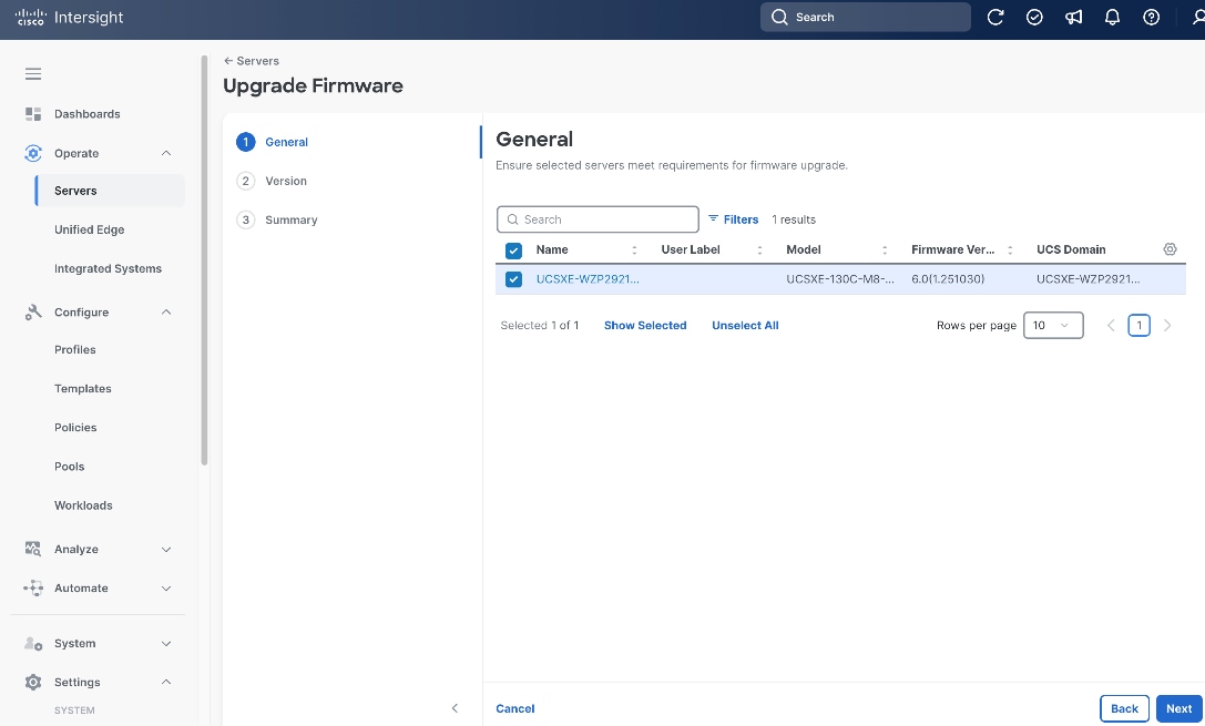
Step 2. On the General page, click Next.
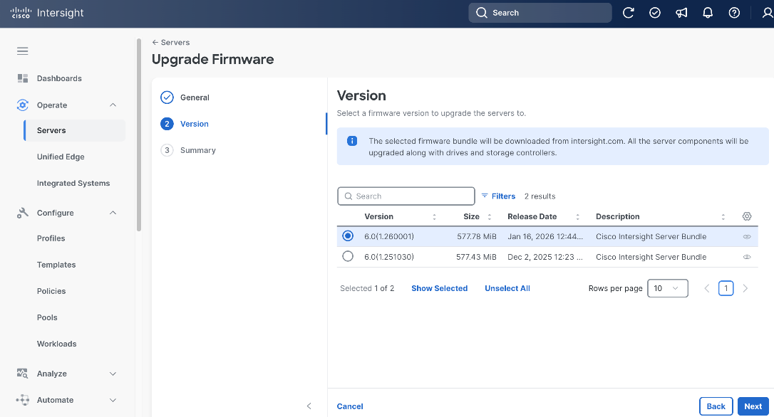
Step 3. On the Version page, choose the target release.
Step 4. Click Next.
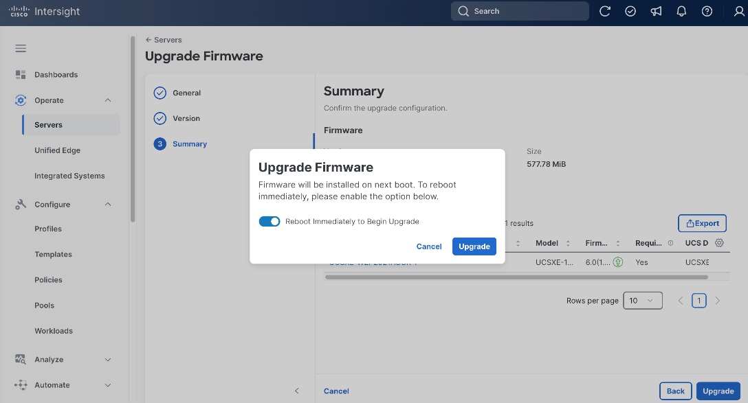
Step 5. On the Summary page, click Upgrade.
Step 6. In the pop-up window, toggle the switch to enable Reboot Immediately to Begin the Upgrade, and click Upgrade.
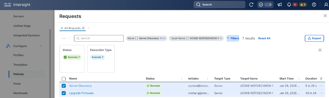
Step 7. Click the checkmark icon at upper-right corner to monitor the status of server firmware upgrade request. It will take a while for the requests Upgrade Firmware and Server Discovery to reach the Success status.
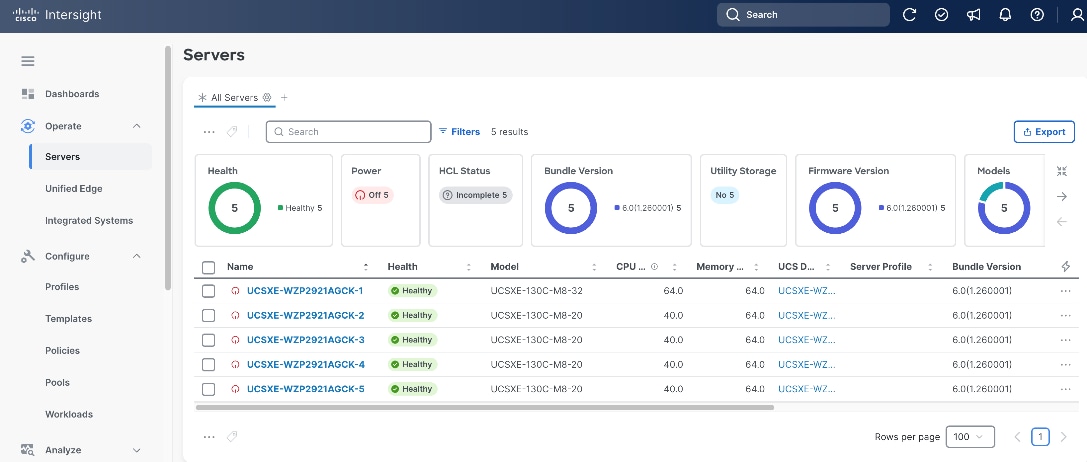
Step 8. Repeat Step 1 – Step 7 to upgrade the firmware for all discovered UCS XE130c M8 servers.
Step 9. Go to Operate > Servers. Verify the Bundle Version shows the correct release number, and the Health status is Healthy for all servers.
Build the Unified Edge Profile Template
A Unified Edge profile is derived from a Unified Edge profile template and is used to configure a Cisco UCS XE9305 chassis through reusable policies. It includes the port and port-channel settings on the eCMCs and provisions the required VLANs. Unified Edge related policies can be attached during profile template creation or added later.
Table 2 lists the policies for Unified Edge that are used in the validated design. All policies are created in the Tenant2 organization and use tenant2 as prefix.
Table 2. Unified Edge policies
| Unified Edge Policy |
Name |
Notes |
| Chassis Configuration |
||
| Thermal |
tenant2-thermal |
Manage temperature based on performance and environment needs. |
| Power |
tenant2-chassis-power |
Control power consumption and recovery after outages |
| Switch Configuration |
||
| VLAN |
tenant2-ecmc-vlan |
Defines the VLANs configured and allowed on eCMCs. |
| Port |
tenant2-ecmc-A-port-channel |
Configure port types and port roles for each eCMC uplink port. This policy for eCMC-A. |
|
|
tenant2-ecmc-B-port-channel |
Configure port types and port roles for each eCMC uplink port. This policy for eCMC-B. |
| Link Aggregation |
tenant2-uplink-aggregation |
Defines LACP settings for eCMC uplink bond interfaces. |
|
|
|
|
| System QoS |
tenant2-qos |
Defines the system-wide QoS classes and bandwidth/priority settings for traffic flows. |
| Switch Control |
tenant2-switch-control |
Global settings at eCMC level to enable and disable Jumbo frames on the embedded switches. |
| Management Configuration |
||
| NTP |
tenant2-ntp |
Specifies NTP servers and time settings |
| Network Connectivity |
tenant2-network-conn-1 |
Defines management network settings, for example, DNS. |
| Local User |
tenant2-local-user |
Creates and manages local user accounts and role-based access on the managed devices. |
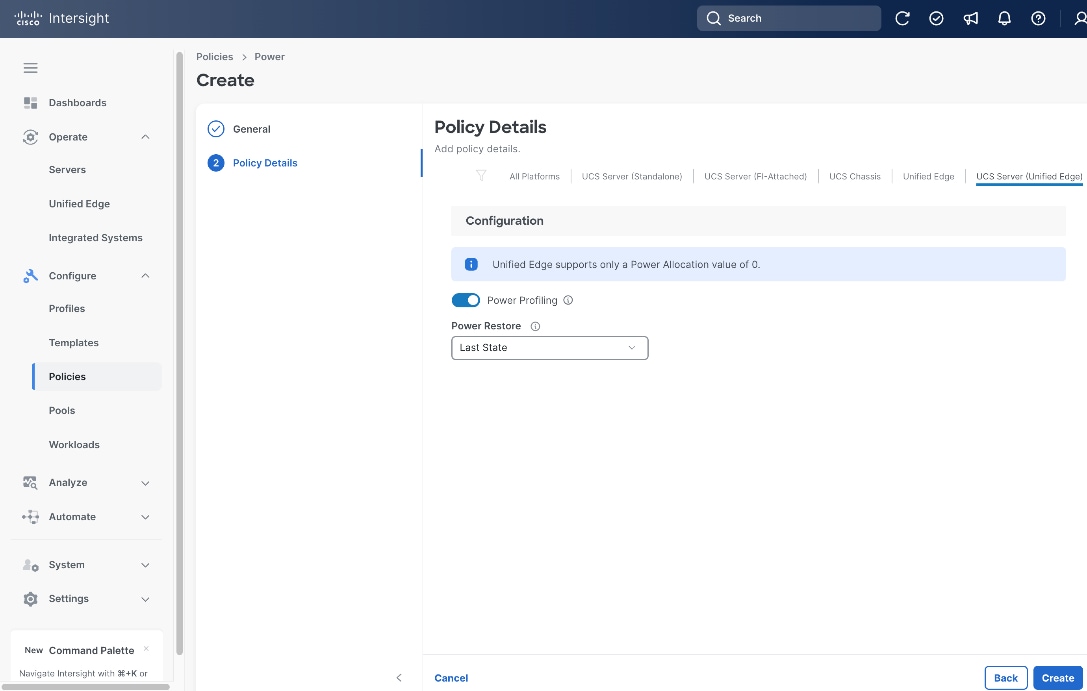
Procedure 1. Configure Power Policy
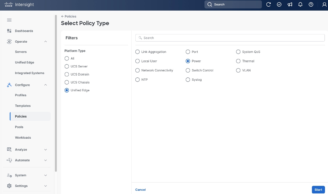
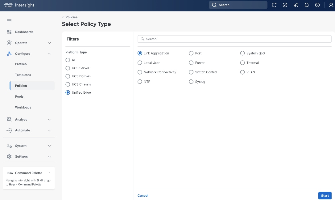
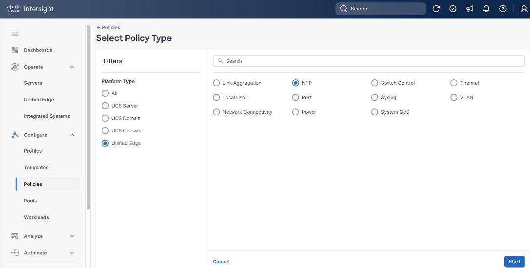
Step 1. Go to Configure > Policies. Click Create Policy.
Step 2. Click Unified Edge in the Filters section, then select Power.
Step 3. Click Start.
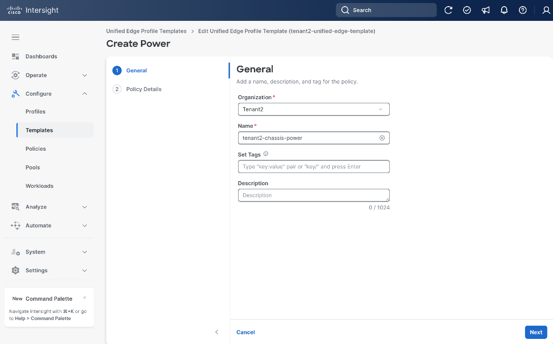
Step 4. On the General page, select the correct Organization, for example, Tenant2.
Step 5. Provide a Name for the policy, for example, tenant2-chassis-power.
Step 6. (Optional) Provide Tags and Description.
Step 7. Click Next.
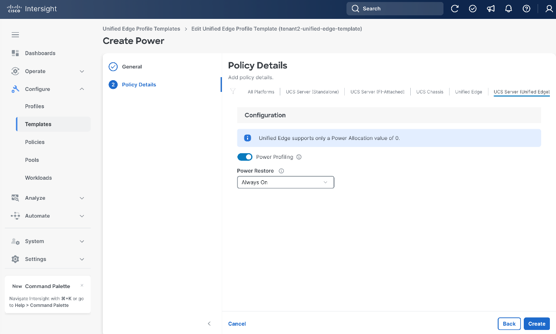
Step 8. On the Policy Details page, set a Power Restore option, for example, Always On.
Step 9. Click Create.
Procedure 2. Configure Thermal Policy
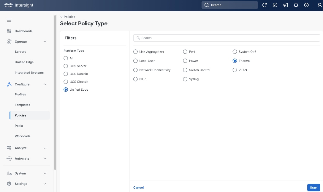
Step 1. Go to Configure > Policies. Click Create Policy.
Step 2. Click Unified Edge in the Filters section, then select Thermal.
Step 3. Click Start.
Step 4. On the General page, select the correct Organization, for example, Tenant2.
Step 5. Provide a name for the policy, for example, tenant2-thermal.
Step 6. (Optional) Provide Tags and Description.
Step 7. Click Next.
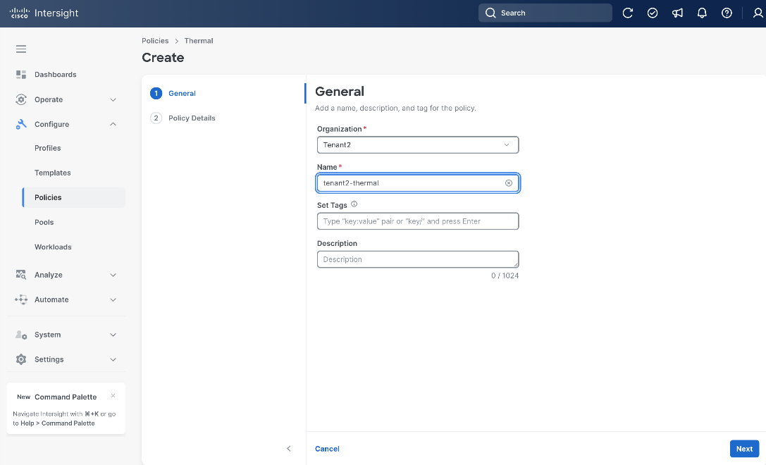
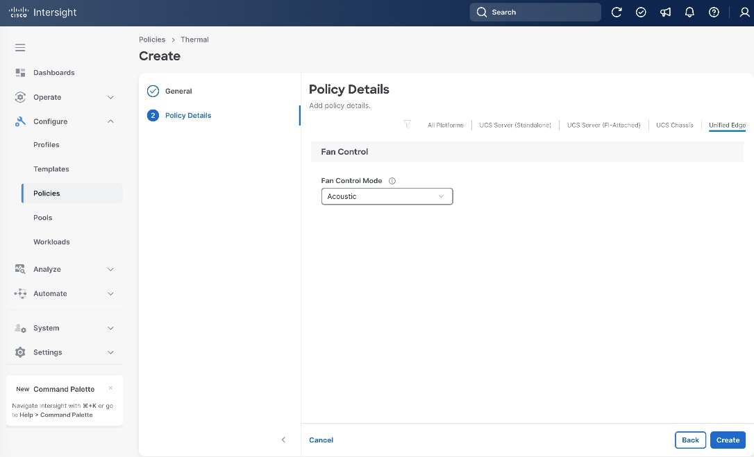
Step 8. On the Policy Details page, click Unified Edge.
Step 9. Select the Fan Control Mode, for example, Acoustic.
Step 10. Click Create.
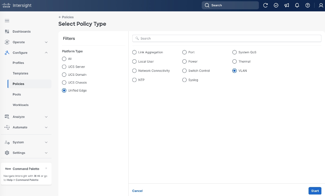
Procedure 3. eCMC VLAN Configuration
Step 1. Go to Configure > Policies. Click Create Policy.
Step 2. Click Unified Edge in the Filters section, then select VLAN.
Step 3. Click Start.
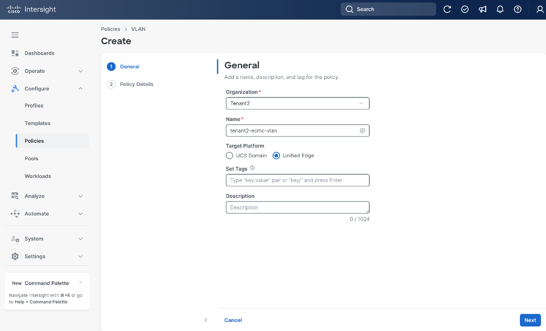
Step 4. On the General page, select the correct Organization, for example, Tenant2.
Step 5. Provide a name for the policy, for example, tenant2-ecmc-vlan.
Step 6. Select Unified Edge as the Target Platform.
Step 7. (Optional) Provide Tags and Description.
Step 8. Click Next.
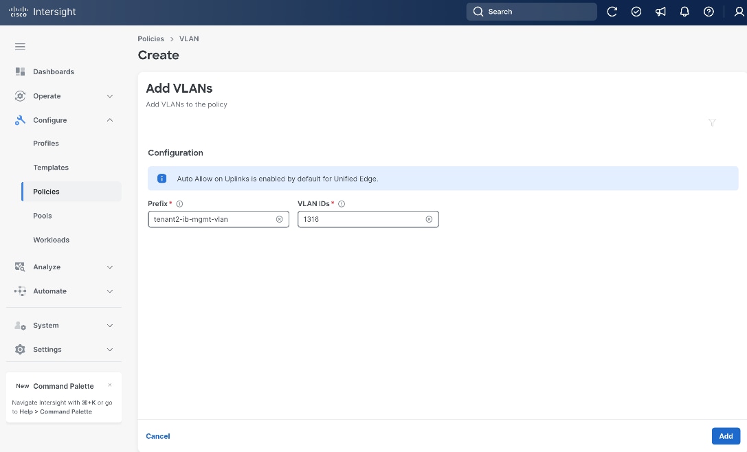
Step 9. On the Policy Details page, click Add VLANs.
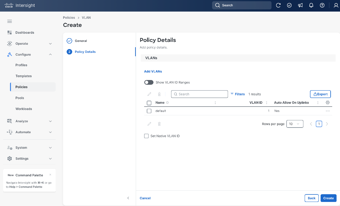
Step 10. Set Prefix as tenant2-ib-mgmt-vlan and VLAN ID to 1316.
Step 11. Click Add.
Step 12. Repeat Step 1 – Step 11 to add more VLANs.
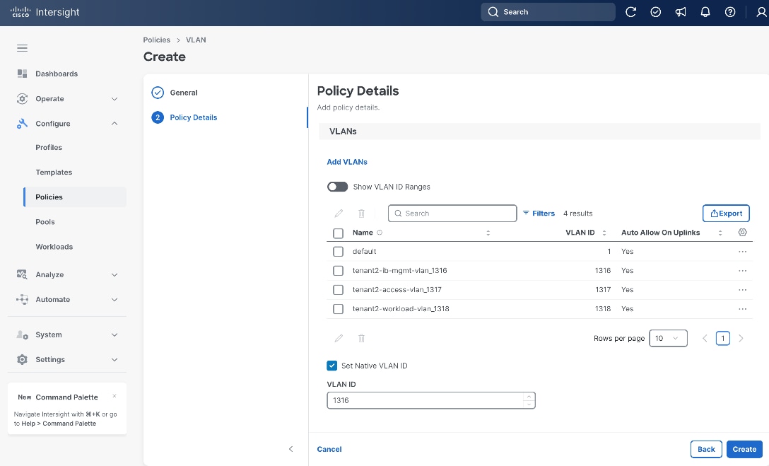
Step 13. From the Policy Details page, set VLAN 1316 as the Native VLAN ID.
Step 14. Click Create.
Procedure 4. Configure Link Aggregation Policy
Step 1. Go to Configure > Policies. Click Create Policy.
Step 2. Click Unified Edge in the Filters section, then select Link Aggregation.
Step 3. Click Start.
Step 4. On the General page, select the correct Organization, for example, Tenant2.
Step 5. Provide a Name for the policy, for example, tenant2-uplink-aggregation.
Step 6. (Optional) Provide Tags and Description.
Step 7. Click Next.
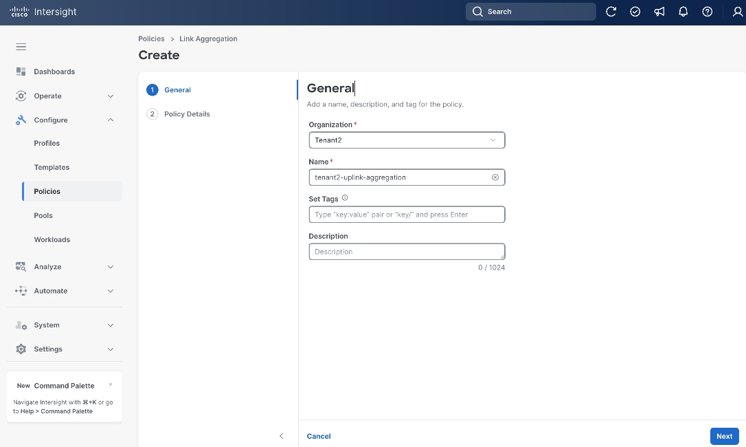
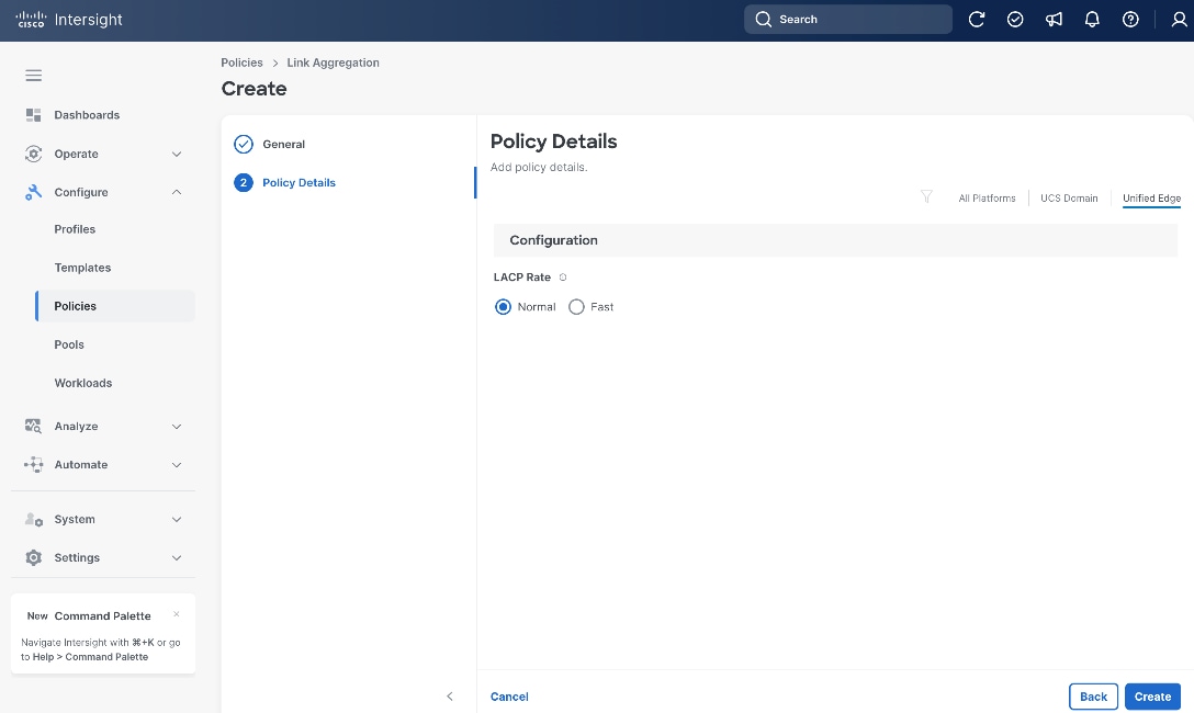
Step 8. On the Policy Details page, click Unified Edge.
Step 9. Leave LACP Rate at its default settings.
Step 10. Click Create.
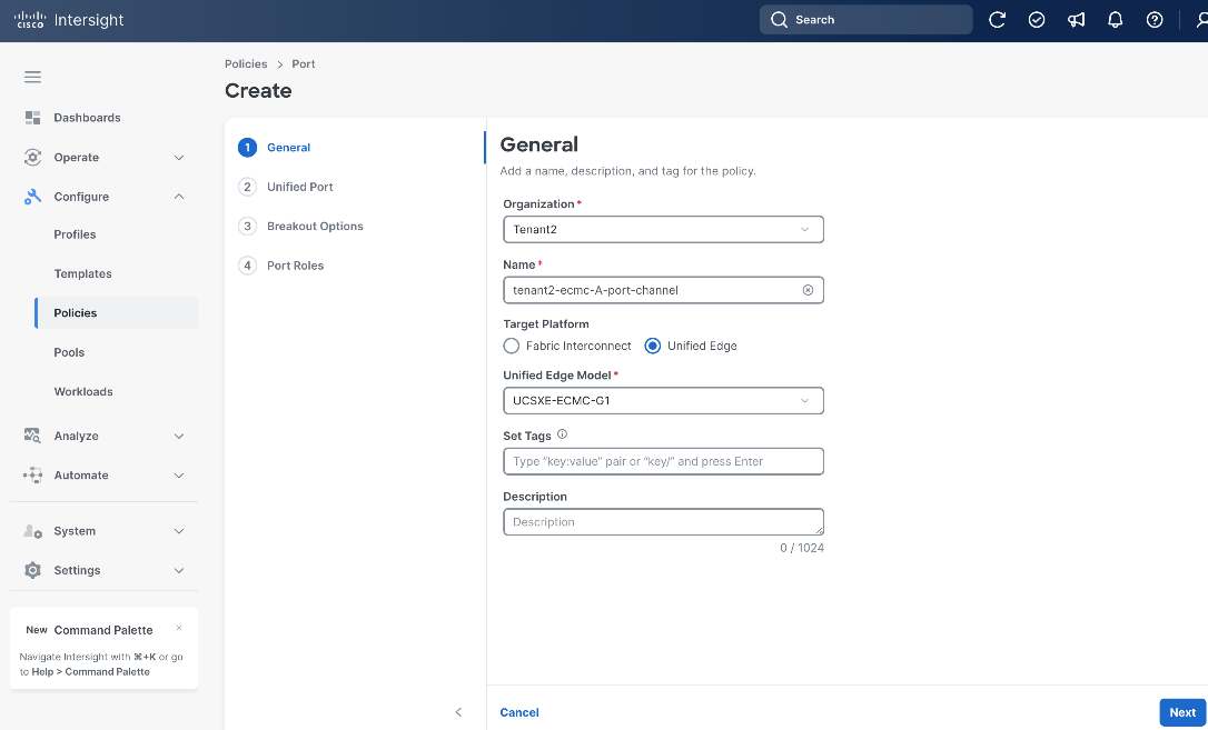
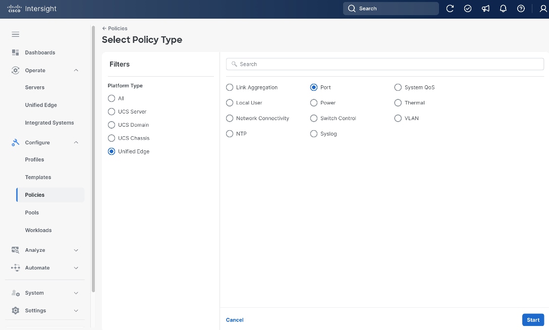
Procedure 5. Configure Port Policy for eCMC A
Step 1. Go to Configure > Policies. Click Create Policy.
Step 2. Click Unified Edge in the Filters section, then select Port.
Step 3. Click Start.

Step 4. On the General page, select the correct Organization, for example, Tenant2.
Step 5. Provide a Name for the policy, for example, tenant2-ecmc-A-port-channel.
Step 6. Select Unified Edge as the Target Platform.
Step 7. For Unified Edge Model, keep the default value, which is UCSXE-eCMC-G1.
Step 8. (Optional) Provide Tags and Description.
Step 9. Click Next.
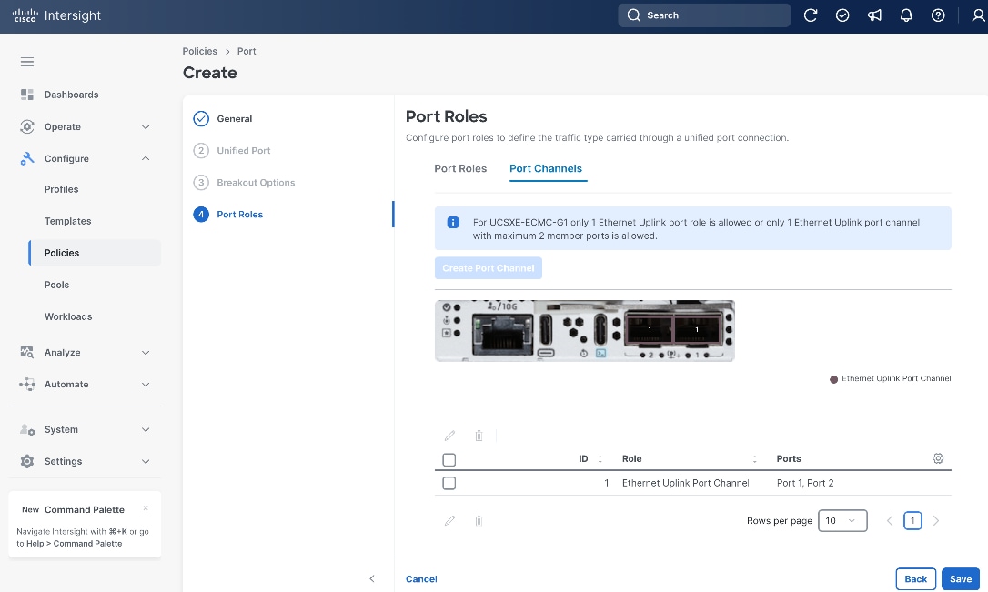
Step 10. On the Port Roles page, click Port Channels tab.
Step 11. Click Create Port Channel.
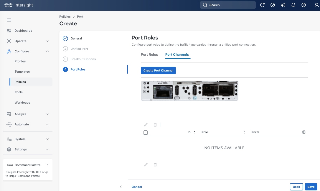
Step 12. On the Create Port Channel page, set Port Channel ID to 1.
Step 13. Under Link Aggregation, choose the Link Aggregation policy that is created in the previous step, for example, tenant2-uplink-aggregation.
Step 14. Select BOTH port1 and port2 toward the bottom of the page.
Step 15. Leave other fields at their default values.
Step 16. Click Save.
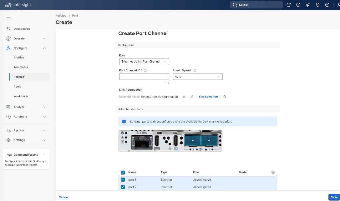
Step 17. Back to Port Roles page, click Save.
Procedure 6. Configure Port Policy for eCMC B
Step 1. Go to Configure > Policies. Click Create Policy.
Step 2. Click Unified Edge in the Filters section, then select Port.
Step 3. Click Start.
Step 4. On the General page, select the correct Organization, for example, Tenant2.
Step 5. Provide a Name for the policy, for example, tenant2-ecmc-B-port-channel.
Step 6. Select Unified Edge as the Target Platform.
Step 7. For Unified Edge Model, leave the default value, which is UCSXE-eCMC-G1.
Step 8. (Optional) Provide Tags and Description.
Step 9. Click Next.

Step 10. On the Port Roles page, click Port Channels tab.
Step 11. Click Create Port Channel.

Step 12. On the Create Port Channel page, set Port Channel ID to 2.
Note: Note: Port Channel IDs must be unique per eCMC. Using the same Port Channel ID on both eCMC-A and eCMC-B will cause a configuration conflict.
Step 13. Under Link Aggregation, choose the Link Aggregation policy that is created in the previous procedure, for example, tenant2-uplink-aggregation.
Step 14. Select BOTH port1 and port2 toward the bottom of the page.
Step 15. Leave other fields at their default values.
Step 16. Click Save.
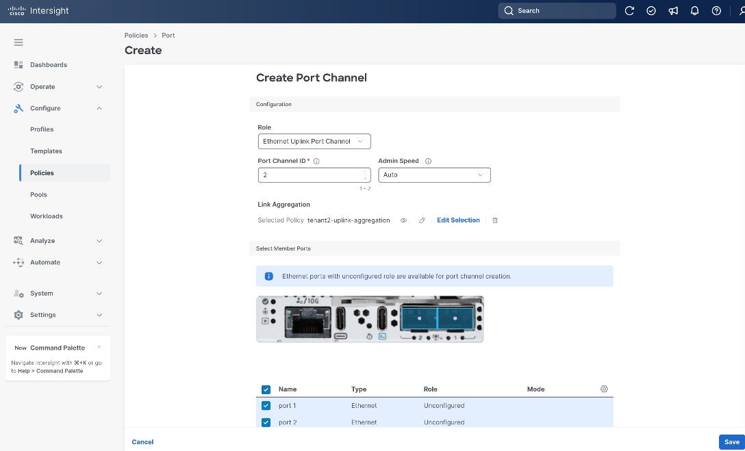
Step 17. Back to Port Roles page, click Save.

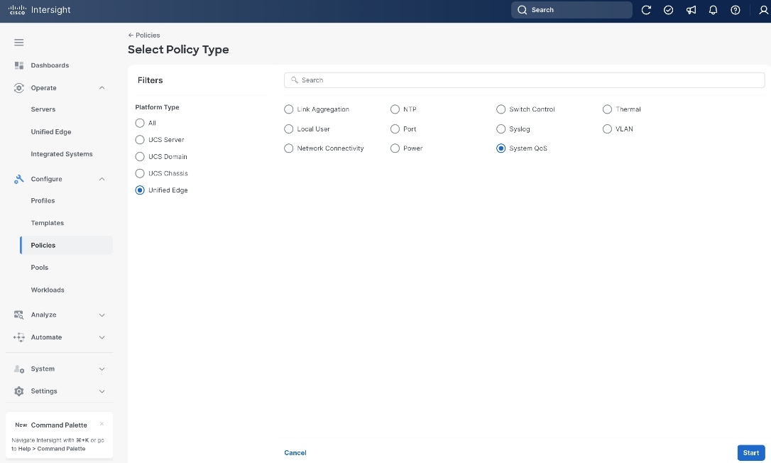
Procedure 7. Configure System QoS Policy
Step 1. Go to Configure > Policies. Click Create Policy.
Step 2. Click Unified Edge in the Filters section, then select System QoS.
Step 3. Click Start.
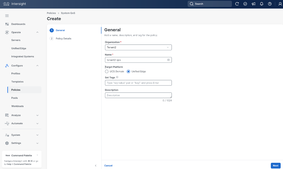
Step 4. On the General page, select the correct Organization, for example, Tenant2.
Step 5. Provide a Name for the policy, for example, tenant2-qos.
Step 6. Select Unified Edge as the Target Platform.
Step 7. (Optional) Provide Tags and Description.
Step 8. Click Next.
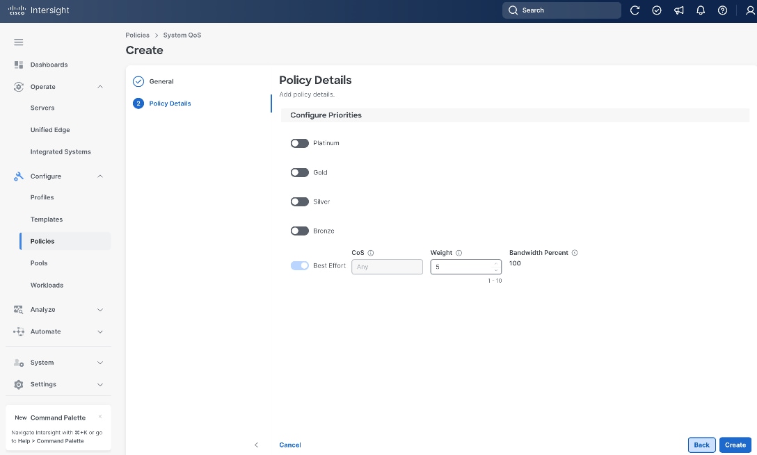
Step 9. On the Policy Details page, leave everything at the default settings.
Step 10. Click Create.
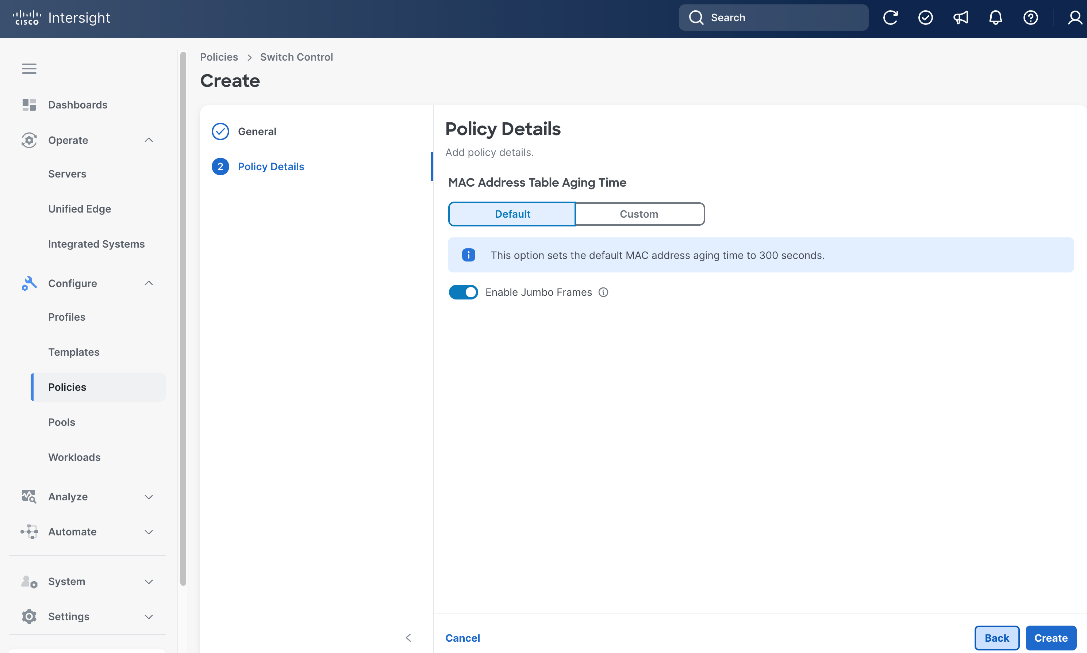
Procedure 8. Configure Switch Control Policy
Step 1. Go to Configure > Policies. Click Create Policy.
Step 2. Click Unified Edge in the Filters section, then select Switch Control.
Step 3. Click Start.

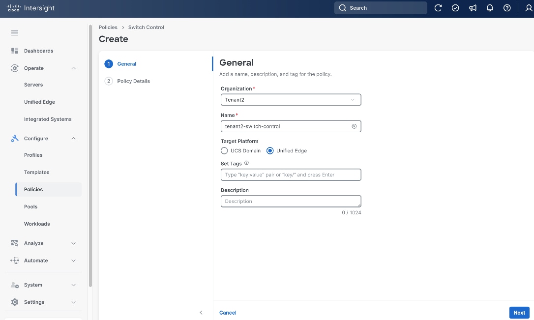
Step 4. On the General page, select the correct Organization, for example, Tenant2.
Step 5. Provide a Name for the policy, for example, tenant2-switch-control.
Step 6. Select Unified Edge as the Target Platform.
Step 7. (Optional) Provide Tags and Description.
Step 8. Click Next.
Step 9. On the Policy Details page, make sure Enable Jumbo Frames is switched on.
Step 10. Leave other fields at their default settings.
Step 11. Click Create.
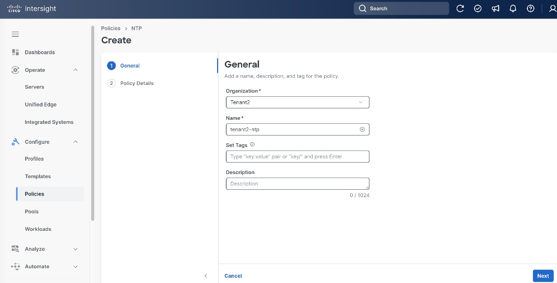
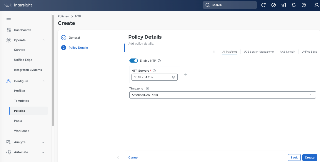
Procedure 9. Configure NTP Policy
Step 1. Go to Configure > Policies. Click Create Policy.
Step 2. Click Unified Edge in the Filters section, then select NTP.
Step 3. Click Start.
Step 4. On the General page, select the correct Organization, for example, Tenant2.
Step 5. Provide a Name for the policy, for example, tenant2-ntp.
Step 6. (Optional) Provide Tags and Description.
Step 7. Click Next.
Step 8. On the Policy Details page, add one or more NTP Servers, for example, 10.81.254.202.
Step 9. Set the Timezone, for example, America/New_York.
Step 10. Click Create.
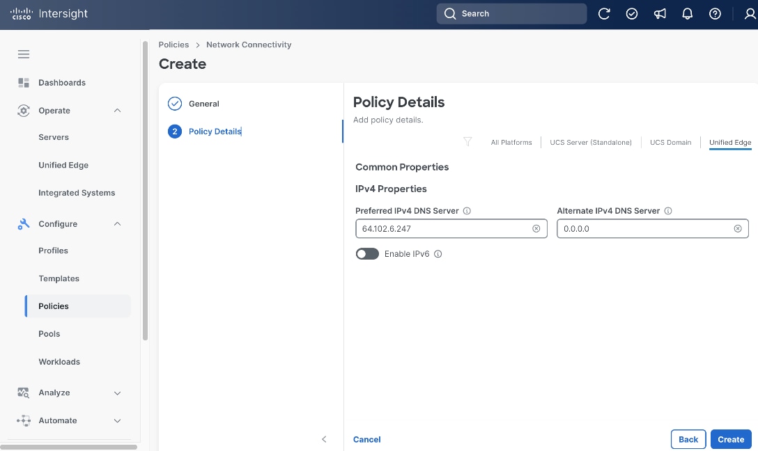
Procedure 10. Configure Network Connectivity Policy
Step 1. Go to Configure > Policies. Click Create Policy.
Step 2. Click Unified Edge in the Filters section, then select Network Connectivity.
Step 3. Click Start.
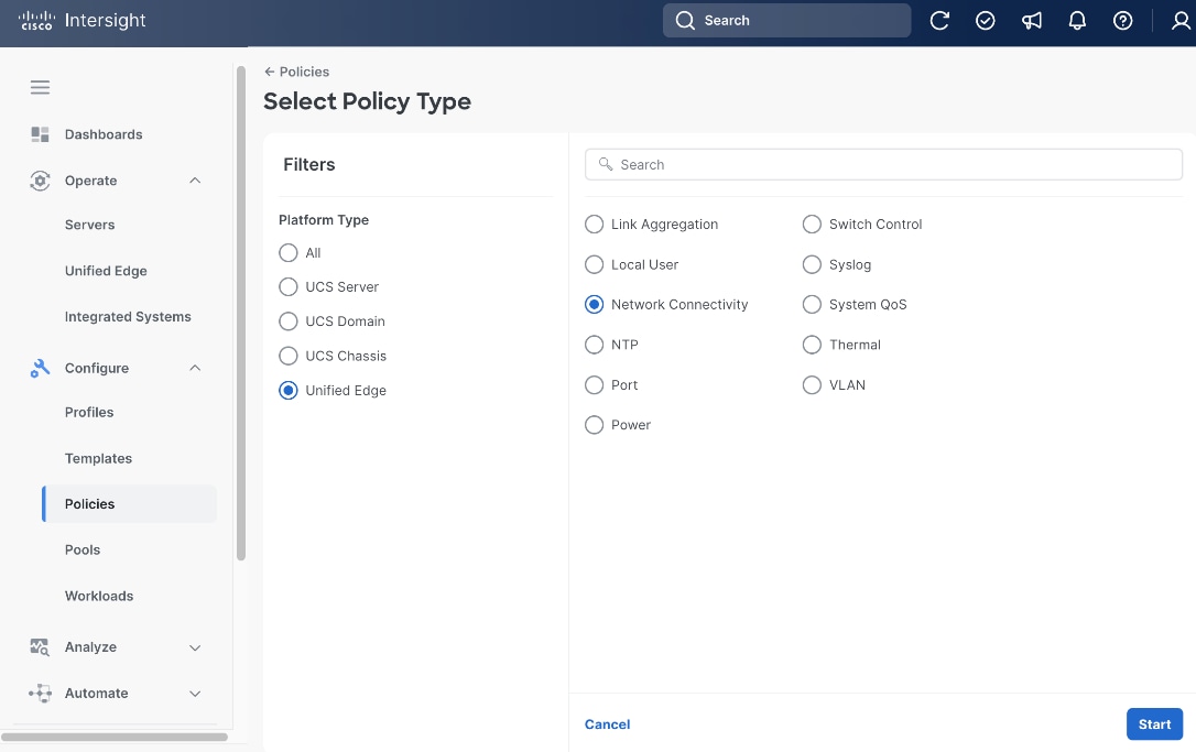
Step 4. On the General page, select the correct Organization, for example, Tenant2.
Step 5. Provide a Name for the policy, for example, tenant2-network-conn-1.
Step 6. (Optional) Provide Tags and Description.
Step 7. Click Next.
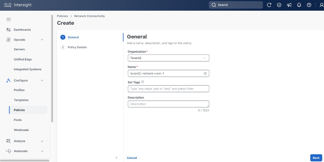
Step 8. On the Policy Details page, click Unified Edge.
Step 9. Provide at least one IPv4 DNS server IP address.
Step 10. Click Create.
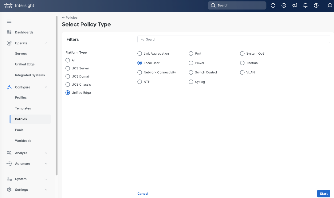
Procedure 11. Configure Local User Policy
Step 1. Go to Configure > Policies. Click Create Policy.
Step 2. Click Unified Edge in the Filters section, then select Local User.
Step 3. Click Start.
Step 4. On the General page, select the correct Organization, for example, Tenant2.
Step 5. Provide a Name for the policy, for example, tenant2-local-user.
Step 6. (Optional) Provide Tags and Description.
Step 7. Click Next.
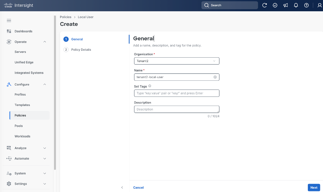
Step 8. On the Policy Details page, click Add New User.
Step 9. Leave Username as admin.
Step 10. Select Role as admin and set Password.
Step 11. Click Create.
Procedure 12. Configure Cisco Unified Edge Profile Templates
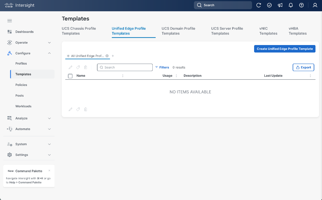
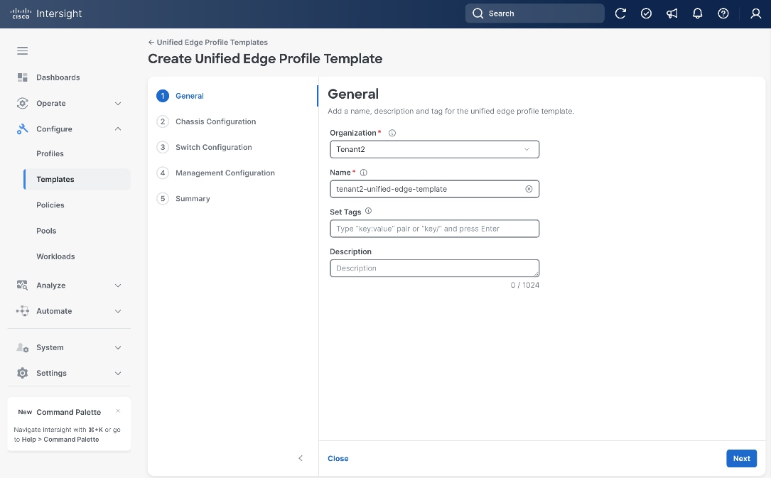
Step 1. Go to Configure > Templates. Select Unified Edge Profile Templates at the top and click Create Unified Edge Profile Template.
Step 2. Select the correct Organization, for example, Tenant2.
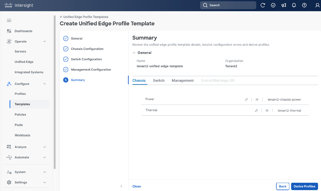
Step 3. Provide a Name for the template, for example, tenant2-unified-edge-template.
Step 4. (Optional) Provide Tags and Description.
Step 5. Click Next.
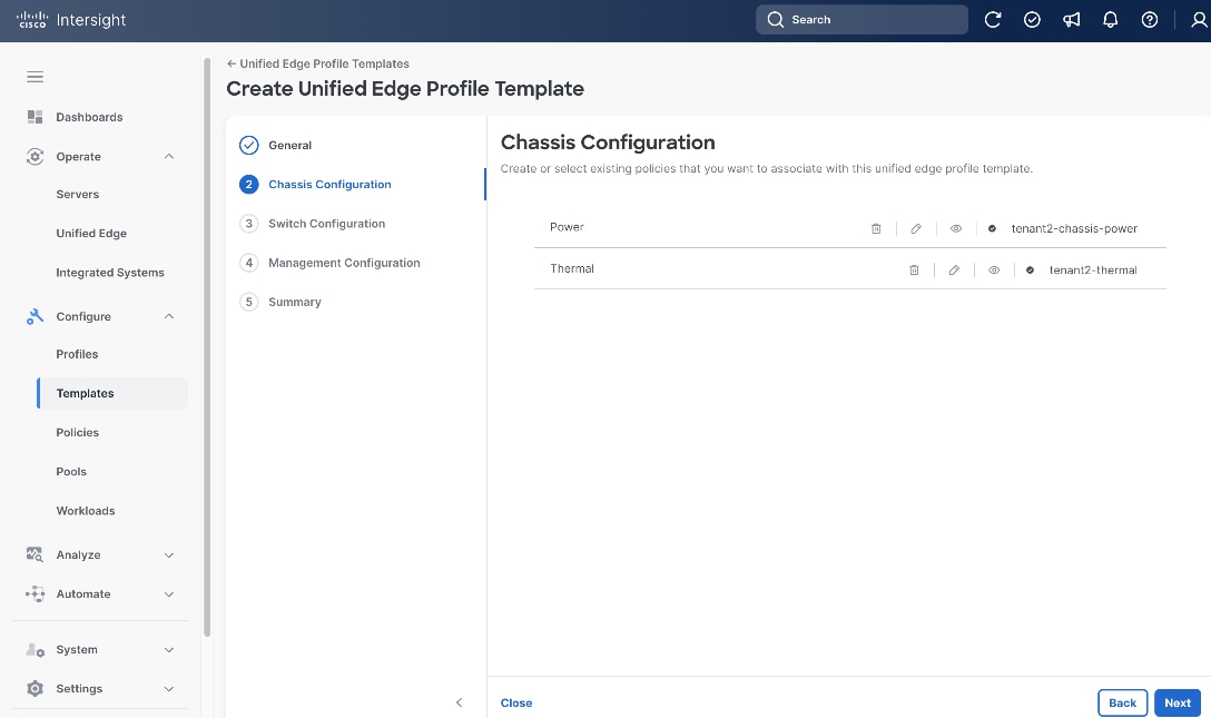
Step 6. On the Chassis Configuration page, click Select Policy next to Power.
Step 7. Select the Power Policy created in the previous step, which is tenant2-chassis-power.
Step 8. Click Select.
Step 9. From the Chassis Configuration page, click Select Policy next to Thermal.
Step 10. Select the Thermal Policy created in the previous step, which is tenant2-thermal.
Step 11. Click Select.
Step 12. From the Chassis Configuration page, click Next.
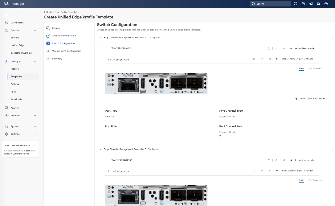
Step 13. On the Switch Configuration page, in the Edge Chassis Management Controller A section, click Select Policy next to VLAN Configuration.
Step 14. Select the VLAN Policy created in the previous step, which is tenant2-ecmc-vlan.
Step 15. Click Select.
Step 16. From the Switch Configuration page, in the Edge Chassis Management Controller A section, click Select Policy next to Ports Configuration.
Step 17. Select the Port Policy for eCMC-A created in the previous step, which is tenant2-ecmc-A-port-channel.
Step 18. Click Select.
Step 19. From the Switch Configuration page, in the Edge Chassis Management Controller B section, click Select Policy next to VLAN Configuration.
Step 20. Select the VLAN Policy created in the previous step, which is tenant2-ecmc-vlan.
Step 21. Click Select.
Step 22. From the Switch Configuration page, in the Edge Chassis Management Controller B section, click Select Policy next to Ports Configuration.
Step 23. Select the Port Policy for eCMC-B created in the previous step, which is tenant2-ecmc-B-port-channel.
Step 24. Click Select.
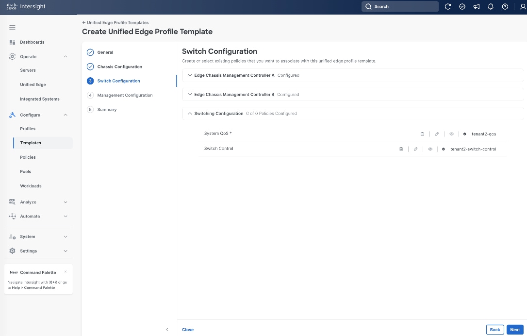
Step 25. From the Switch Configuration page, in the Switching Configuration section, click Select Policy next to System QoS.
Step 26. Select the QoS Policy created in the previous step, which is tenant2-qos.
Step 27. Click Select.
Step 28. From the Switch Configuration page, in the Switching Configuration section, click Select Policy next to Switch Control.
Step 29. Select the Switch Control Policy created in the previous step, which is tenant2-switch-control.
Step 30. Click Select.
Step 31. From the Switch Configuration page, click Next.
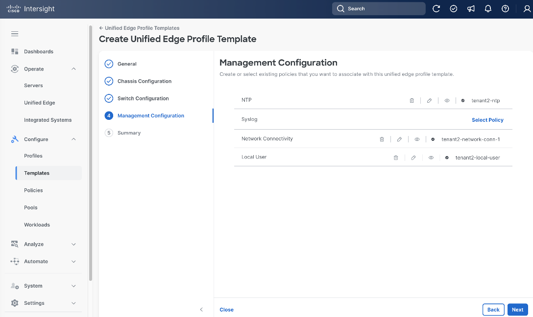
Step 32. On the Management Configuration page, click Select Policy next to NTP.
Step 33. Select the NTP Policy created in the previous step, which is tenant2-ntp.
Step 34. Click Select.
Step 35. From the Management Configuration page, click Select Policy next to Network Connectivity.
Step 36. Select the Network Connectivity Policy created in the previous step, which is tenant2-network-conn-1.
Step 37. Click Select.
Step 38. From the Management Configuration page, click Select Policy next to Local User.
Step 39. Select the Local User Policy created in the previous step, which is tenant2-local-user.
Step 40. Click Select.
Step 41. From the Management Configuration page, click Next.
Step 42. On the Summary page, click Derive Profiles.
Apply Unified Edge Configuration
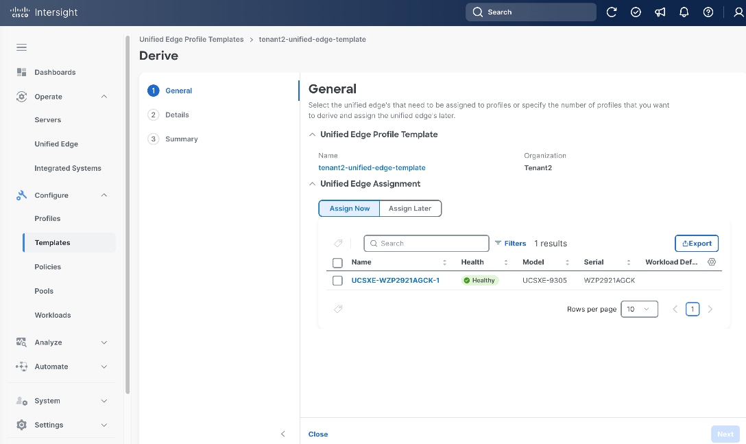
Procedure 1. Derive and Assign Cisco Unified Edge Profile
Step 1. On the General page, select the newly claimed Unified Edge Chassis in the Unified Edge Assignment section.
Step 2. Click Next.
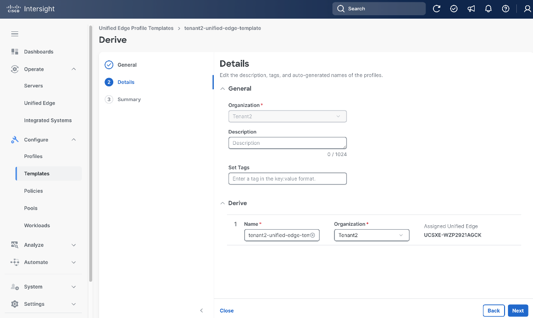
Step 3. On the Details page, select the correct Organization, for example, Tenant2.
Step 4. (Optional) Provide Description and Tags.
Step 5. Leave the other fields at their default settings.
Step 6. Click Next.
Step 7. On the Summary page, click Derive.
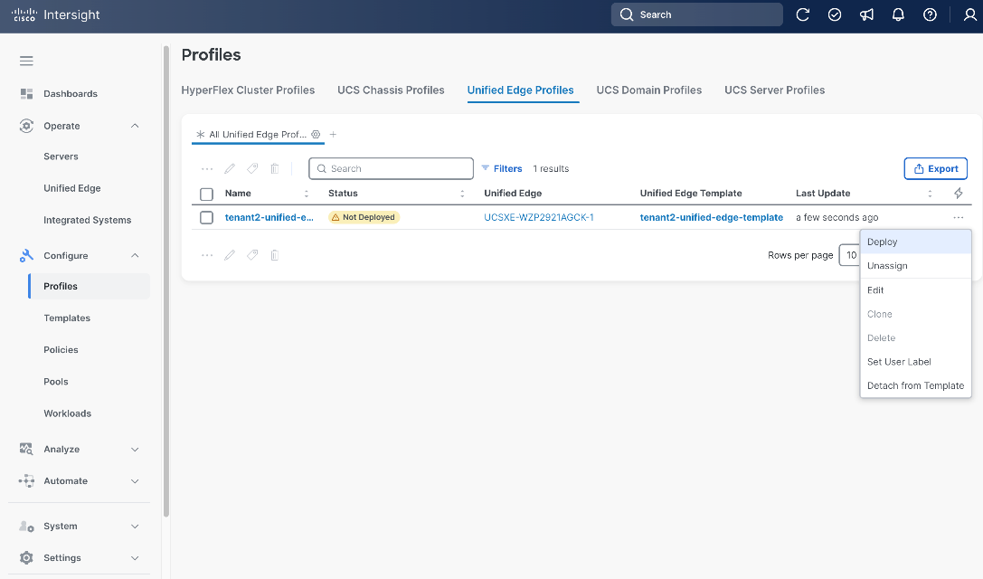
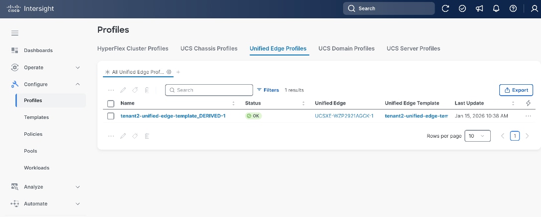
Step 8. Go to Configure > Profiles.
Step 9. Click Unified Edge Profiles.
Step 10. Select the newly created Unified Edge Profile.
Step 11. Click the ellipsis (…) at the end of the row. In the drop-down list, click Deploy.
Step 12. Click Deploy in the pop-up window.
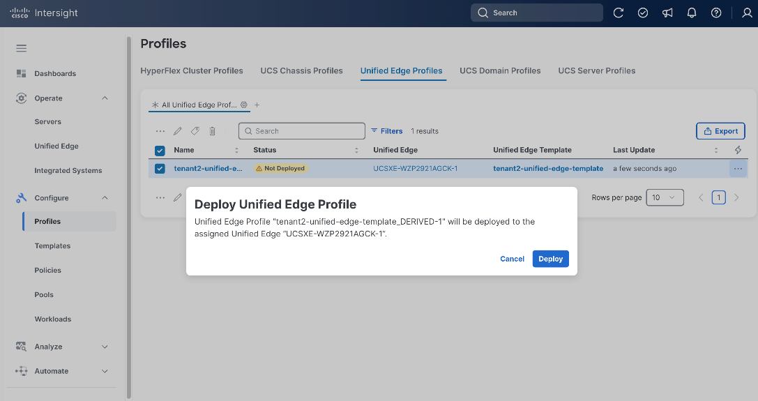
Step 13. The deployment will take a while to complete. Click the checkmark icon at the upper-right corner to check the status of the profile deployment request.
Step 14. Go to Configure > Profiles. Verify that the Unified Edge profile has been successfully deployed. The Status should be OK.
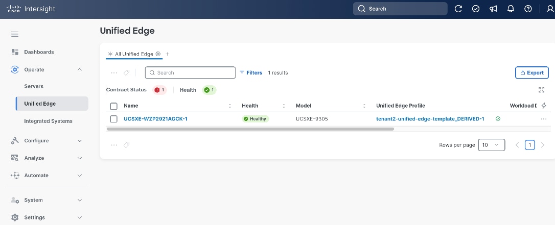
Step 15. Go to Operate > Unified Edge. Verify that the Health status of the newly added UCS XE9305 is Healthy.
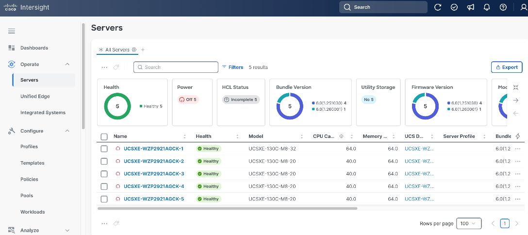
Step 16. Go to Operate > Servers and verify that all UCS XE130c M8 servers on UCS XE9305 chassis have been successfully discovered.
Create Server Profile Template
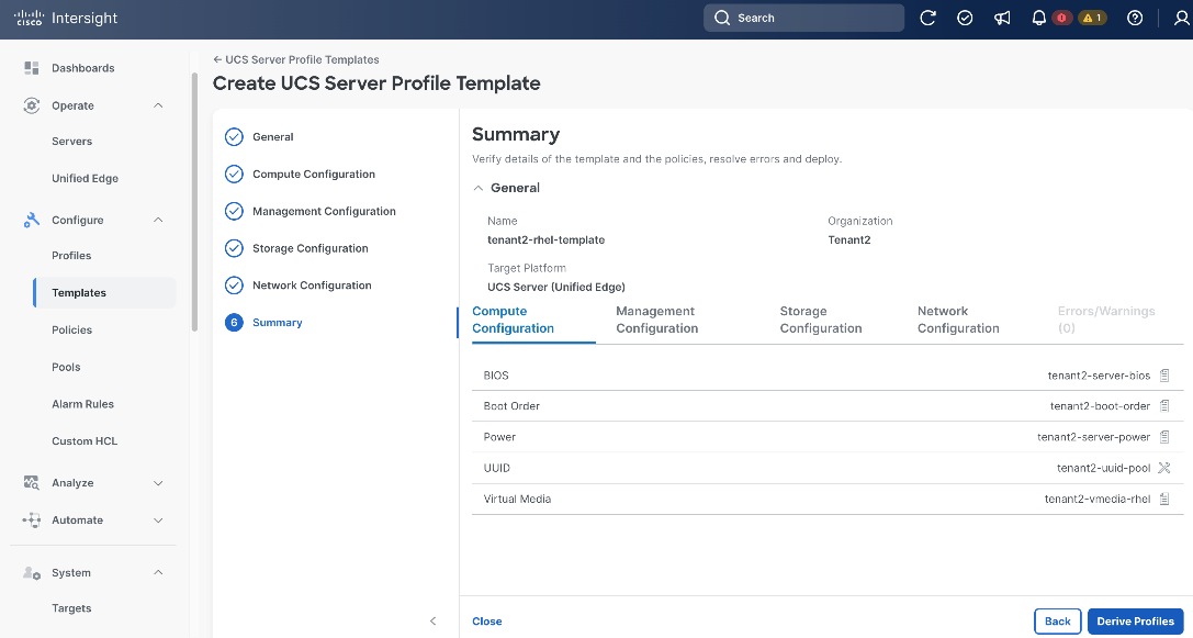
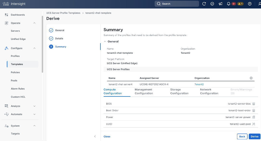
A server profile template enables resource management by simplifying policy alignment and server configuration. A server profile template is created using the server profile template wizard. Server Profiles are derived from Server Profile Templates and applied on Cisco UCS XE130c M8 servers that are discovered in Cisco Intersight. For RHEL deployments, the server profile defines the boot order, storage, network connectivity, and virtual media policies required to install and operate the RHEL host.
Table 3 lists a summary view of the policies used in the validated design.
| Type |
Name |
Notes |
| Compute Configuration |
||
| BIOS |
tenant2-server-bios |
Sets BIOS configuration options for CPU, memory, virtualization, and platform features. |
| Boot Order |
tenant2-boot-order |
Specifies the boot device sequence and boot mode. |
| Power |
tenant2-server-power |
Control server power consumption and recovery after power events. |
| Virtual Media |
tenant2-vmedia-rhel |
Enables mounting the RHEL installation ISO image to the server over the network |
| Management Configuration |
||
| IMC Access |
tenant2-imc |
Defines the management IP address pool for KVM access. |
| Local User |
tenant2-local-user |
Used to enable KVM-based user access |
| Virtual KVM |
tenant2-vKVM |
Configures KVM and remote console access settings. |
| Storage Configuration |
||
| Storage |
tenant2-storage |
Defines storage configuration such as controller mode, RAID settings, and virtual drive parameters. |
| Network Configuration |
||
| LAN Connectivity |
tenant2-lan-conn-rhel |
Defines vNIC configuration and network connectivity. Establishes how the server connects to embedded switches on eCMCs. |
| Ethernet QoS |
tenant2-eth-qos |
Defines traffic priority, bandwidth limits, MTU, and Quality of Service parameters for vNIC Ethernet traffic. |
| Ethernet Network Group |
tenant2-eth-netgrp-rhel |
Specifies VLAN assignments and network groupings that can be applied to vNICs. |
Table 4 lists the pools used in the validated design.
| Type |
Name |
Notes |
| UUID |
tenant2-uuid-pool |
Provides a range of UUID assigned to server profiles for server identification. |
| IP |
tenant2-inband-mgmt |
Range of IP addresses for server inband management. |
Procedure 1. Create UUID Pool
Step 1. Go to Configure > Pools.
Step 2. Click Pools and then click Create Pool.
Step 3. On the Create page, select UUID.
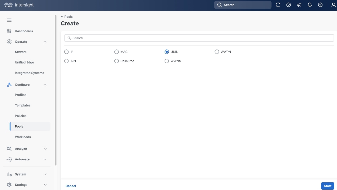
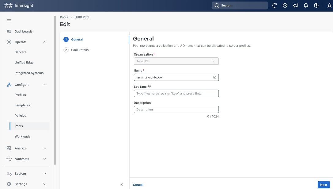
Step 4. On General page, select the correct Organization, for example, Tenant2.
Step 5. Provide a Name for the pool, for example, tenant2-uuid-pool.
Step 6. (Optional) Provide Tags and Description.
Step 7. Click Next.
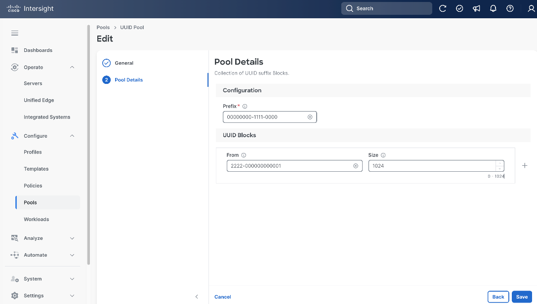
Step 8. On the Pool Details page, in Prefix section set the prefix. In this example, it is 00000000-1111-0000.
Step 9. In UUID Blocks section, set the range of UUID by specifying From and Size. In this example, they are 2222-000000000001 and 1024, respectively.
Step 10. Click Save.
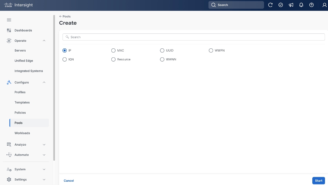
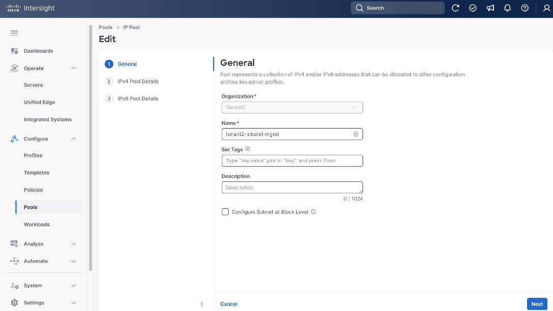
Procedure 2. (Optional) Create Inband Management IP Pool
Step 1. Go to Configure > Pools, click the Pools tab and then click Create Pool.
Step 2. On the Create page, select IP.
Step 3. On the General page, select the correct Organization, for example, Tenant2.
Step 4. Provide a Name for the pool, for example, tenant2-inband-mgmt.
Step 5. (Optional) Provide Tags and Description.
Step 6. Click Next.
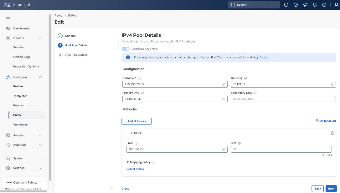
Step 7. On the IPv4 Pool Details page, in Configuration section, set Netmask, Gateway and Primary DNS. In this example, they are 255.255.255.0, 10.131.6.1 and 64.102.6.247, respectively.
Step 8. In IP Blocks section, set the range of IP by specifying From and Size. In this example, they are 10.131.6.101 and 50, respectively.
Step 9. Click Next.
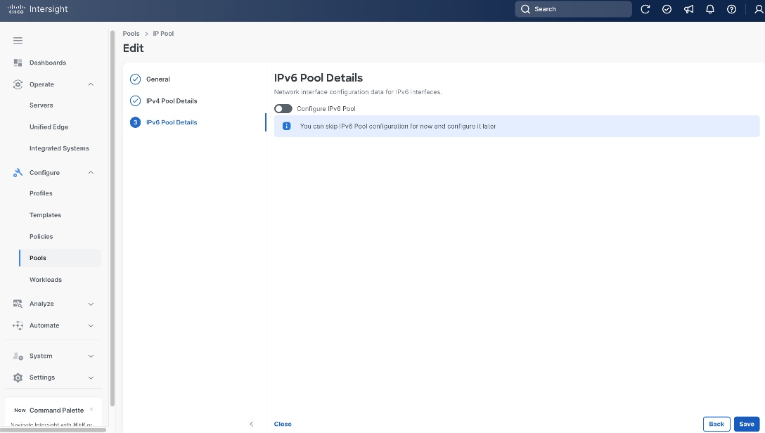
Step 10. On the IPv6 Pool Details page, leave Configure IPv6 Pool switch off.
Step 11. Click Save.
Procedure 3. Create BIOS Policy
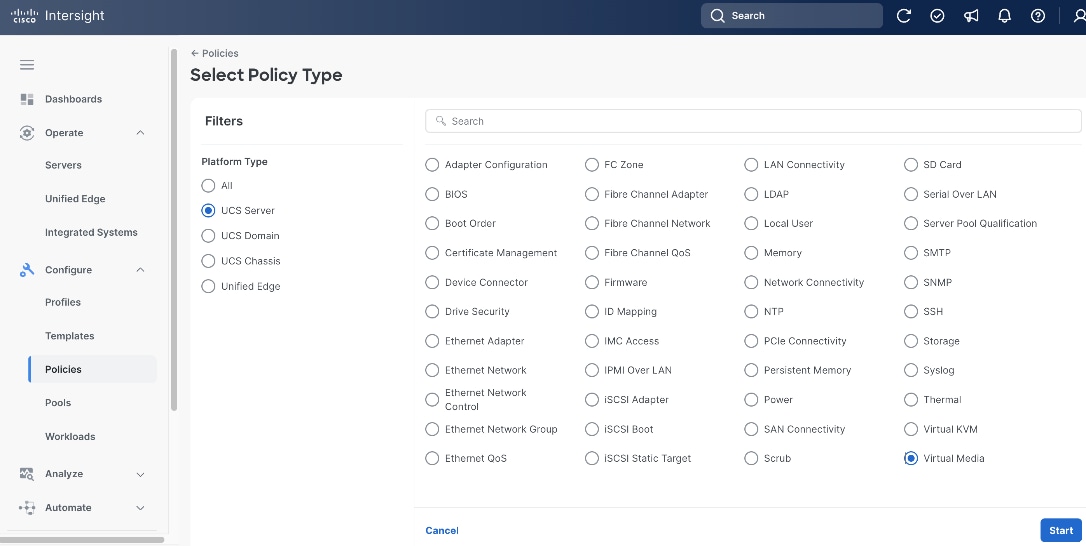
Step 1. Go to Configure > Policies and then click Create Policy.
Step 2. On the Select Policy Type page, click UCS Server in the Filters section, then select BIOS.
Step 3. Click Start.

Step 4. On the General page, select the correct Organization, for example, Tenant2.
Step 5. Provide a Name for the policy, for example, tenant2-server-bios.
Step 6. (Optional) Provide Tags and Description.
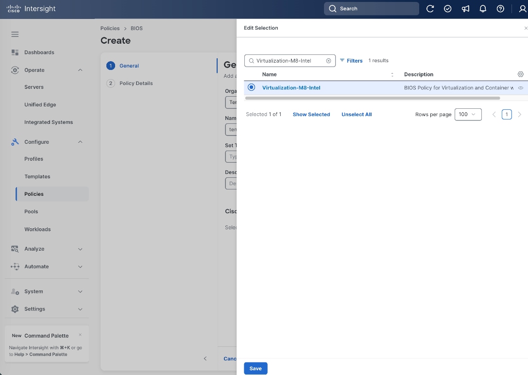
Step 7. In the Cisco Provided BIOS Configuration section, click Select Cisco Provided Configuration.
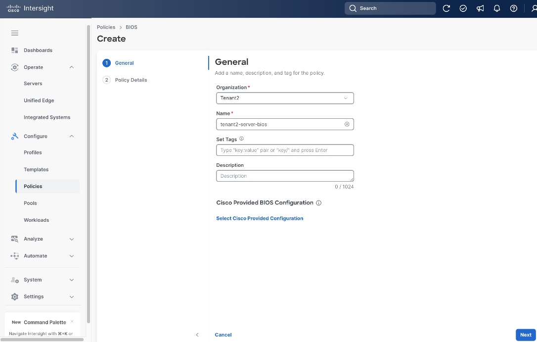
Step 8. Search Virtualization-M8-Intel, then click Select.
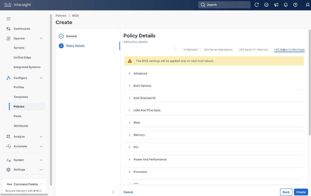
Step 9. From the General page, click Create.
Step 10. On the Policy Details page, click UCS Server (Unified Edge).
Step 11. Click Create.
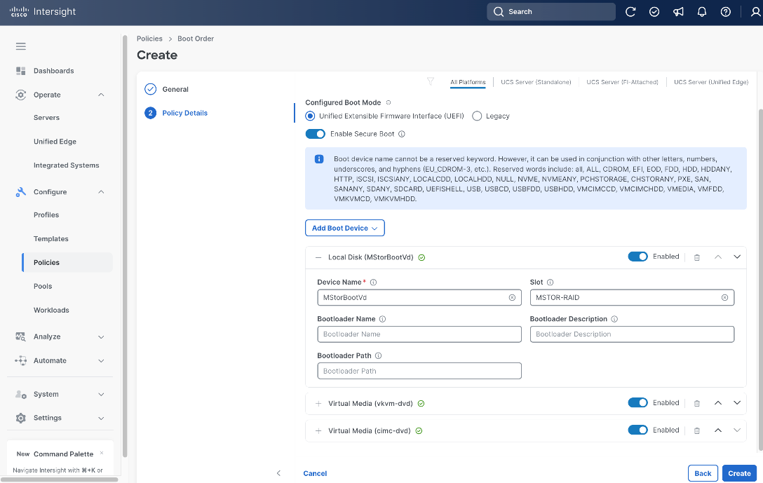
Procedure 4. Create Server Boot Order Policy
Step 1. Click Configure > Policies and then click Create Policy.
Step 2. On the Select Policy Type page, click UCS Server in the Filters section, then select Boot Order.
Step 3. Click Start.

Step 4. On the General page, select the correct Organization, for example, Tenant2.
Step 5. Provide a Name for the policy, for example, tenant2-boot-order.
Step 6. (Optional) Provide Tags and Description.
Step 7. Click Next.

Step 8. On the Policy Details page, in the Configured Boot Mode section, select Unified Extensible Firmware Interface (UEFI).
WARNING!: Enabling Secure Boot on a server equipped with an NVIDIA GPU will prevent the NVIDIA drivers from loading. Verify GPU presence before proceeding.
Step 9. Configure Secure Boot based on your hardware configuration:
● If your server does NOT have an NVIDIA GPU: Toggle the switch ON to enable Secure Boot.
● If your server HAS an NVIDIA GPU: Leave Enable Secure Boot toggled OFF. Enabling Secure Boot on GPU-equipped servers will prevent NVIDIA drivers from loading, rendering the GPU inaccessible.
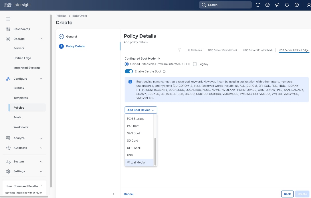
Step 10. From the Add Boot Device drop-down list, select Virtual Media.
Step 11. Set Device Name, for example, cimc-dvd, and choose CIMC MAPPED DVD as the Sub-Type.
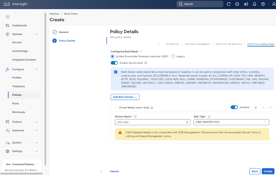
Step 12. From the Add Boot Device drop-down list, select Virtual Media again.
Step 13. Set Device Name, for example kvm-dvd, and choose KVM MAPPED DVD as the Sub-Type.
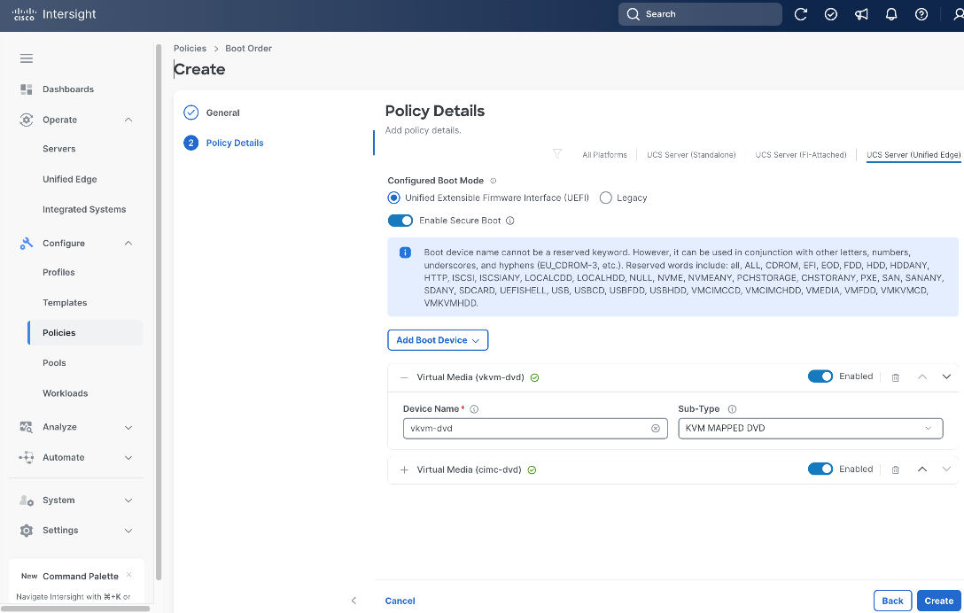
Step 14. From the Add Boot Device drop-down list, select Local Disk.
Step 15. In Local Disk section, enter MStorBootVd as the Device Name.
Step 16. In the Slot field, enter MSTOR-RAID.
Step 17. Click Create.
Procedure 5. Create Server Power Policy
Step 1. Click Configure > Policies and then click Create Policy.
Step 2. On the Select Policy Type page, click UCS Server in the Filters section, then select Power.
Step 3. Click Start.

Step 4. On the General page, select the correct Organization, for example, Tenant2.
Step 5. Provide a Name for the policy, for example, tenant2-server-power.
Step 6. (Optional) Provide Tags and Description.
Step 7. Click Next.

Step 8. On the Policy Details page, from the Power Restore drop-down list, select Last State.
Step 9. Click Create.
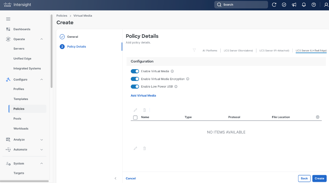
Procedure 6. Create Server Virtual Media Policy
Step 1. Click Configure > Policies and then click Create Policy.
Step 2. On the Select Policy Type page, click UCS Server in the Filters section, then select Virtual Media.
Step 3. Click Start.
Step 4. On the General page, select the correct Organization, for example, Tenant2.
Step 5. Provide a Name for the policy, for example, tenant2-vmedia-rhel.
Step 6. (Optional) Provide Tags and Description.
Step 7. Click Next.
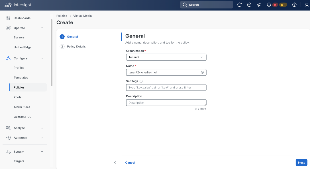
Step 8. Leave all fields at their default settings.
Step 9. Click Create.
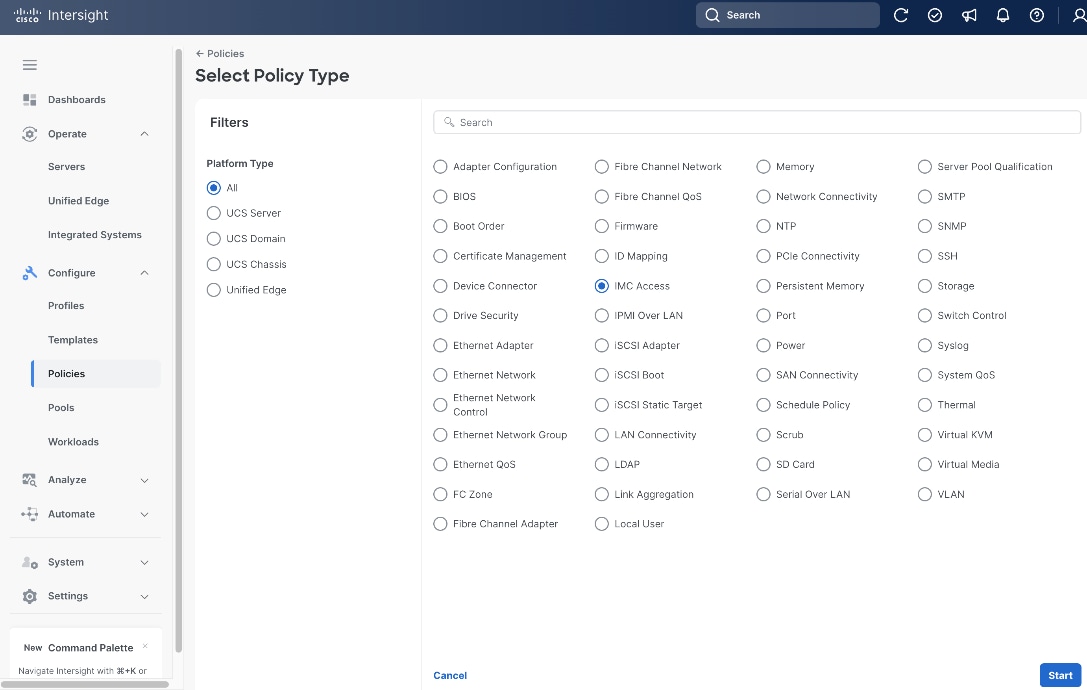
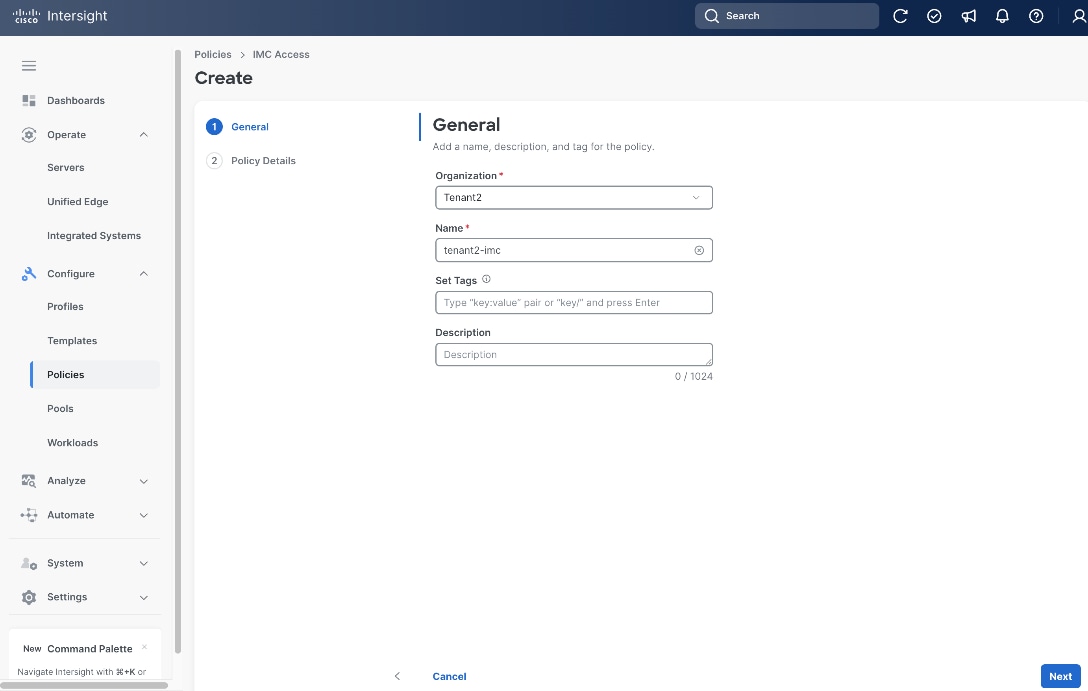
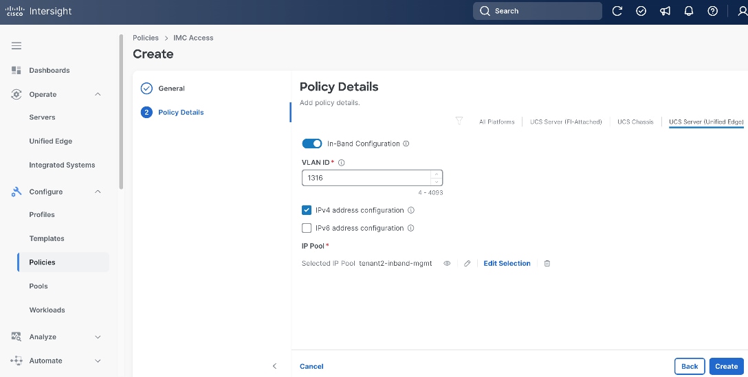
Procedure 7. Create Server IMC Access Policy
Step 1. Click Configure > Policies and then click Create Policy.
Step 2. On the Select Policy Type page, click UCS Server in the Filters section, then select IMC Access.
Step 3. Click Start.
Step 4. On the General page, select the correct Organization, for example, Tenant2.
Step 5. Provide a Name for the policy, for example, tenant2-imc.
Step 6. (Optional) Provide Tags and Description.
Step 7. Click Next.
Step 8. Click UCS Server (Unified Edge).
Step 9. Toggle the switch to enable In-Band Configuration and specify the VLAN ID for the purpose of in-band management, for example, VLAN 1316.
Step 10. In IP Pool section, select the IP Pool tenant2-inband-mgmt we created in the previous step.
Step 11. Click Create.
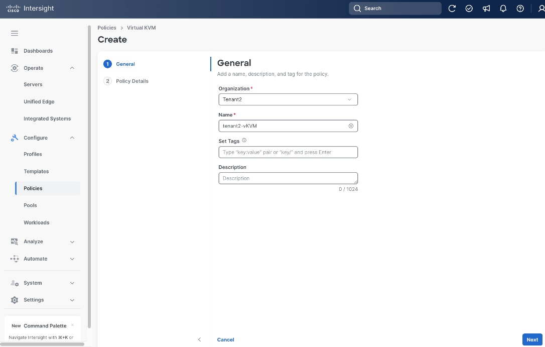
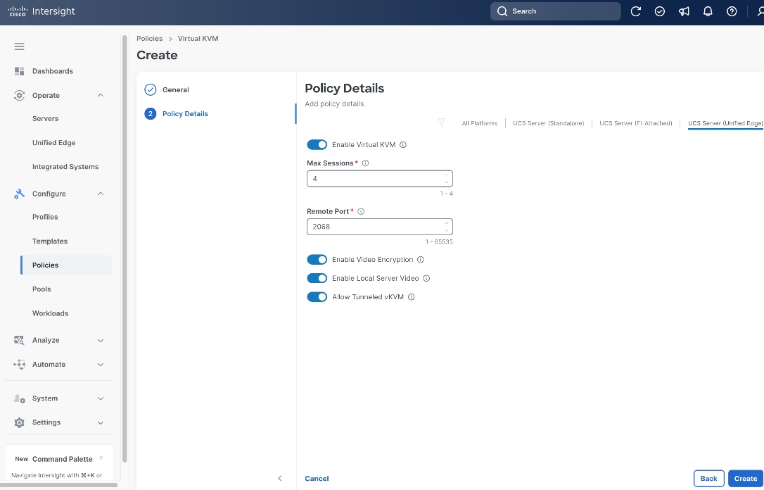
Procedure 8. Create Server Virtual KVM Policy
Step 1. Click Configure > Policies and then click Create Policy.
Step 2. On the Select Policy Type page, click UCS Server in the Filters section, then select Virtual KVM.
Step 3. Click Start.

Step 4. On the General page, select the correct Organization, for example, Tenant2.
Step 5. Provide a Name for the policy, for example, tenant2-vKVM.
Step 6. (Optional) Provide Tags and Description.
Step 7. Click Next.
Step 8. Click UCS Server (Unified Edge).
Step 9. Toggle the switch to enable Allow Tunneled vKVM. Leave all other fields at their default settings.
Step 10. Click Create.
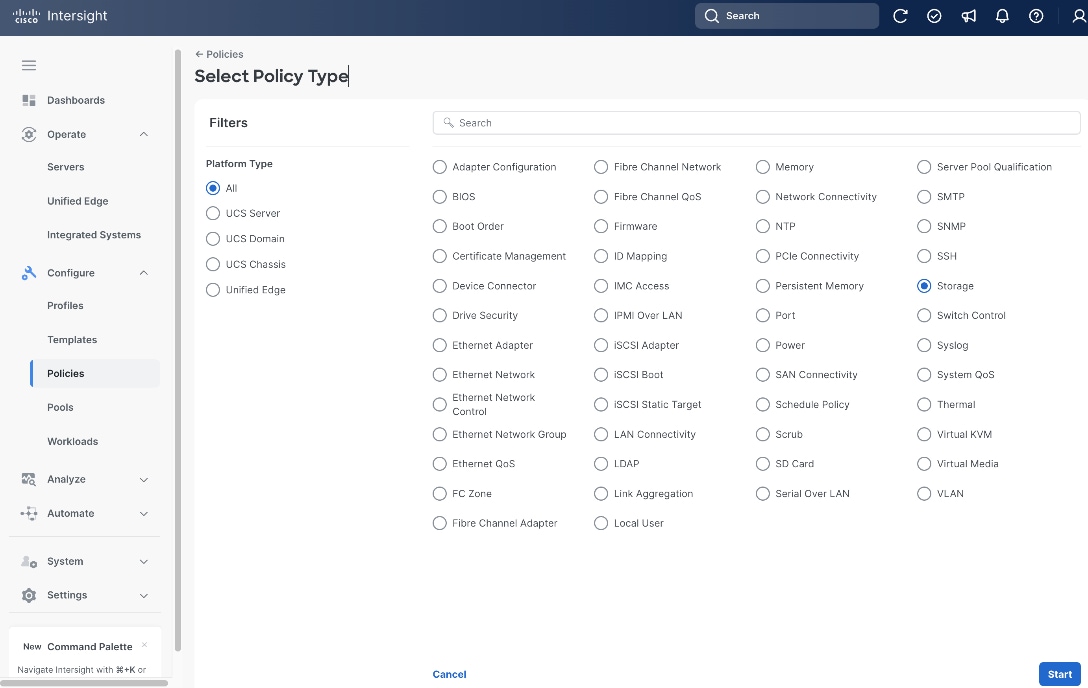
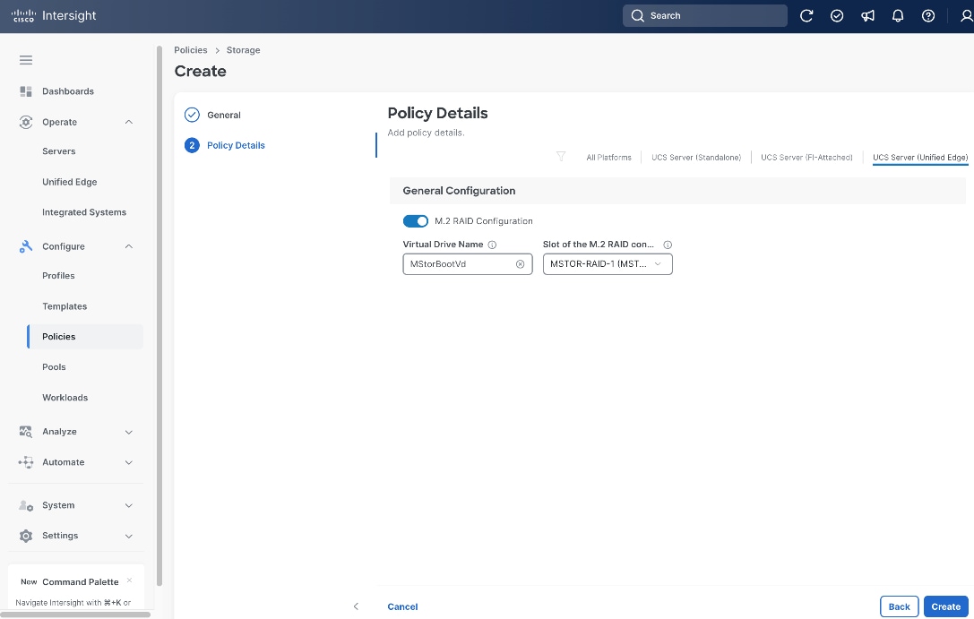
Procedure 9. Create Server Storage Policy
Step 1. Click Configure > Policies and then click Create Policy.
Step 2. On the Select Policy Type page, click UCS Server in the Filters section, then select Storage.
Step 3. Click Start.
Step 4. On the General page, select the correct Organization, for example, Tenant2.
Step 5. Provide a Name for the policy, for example, tenant2-storage.
Step 6. (Optional) Provide Tags and Description.
Step 7. Click Next.
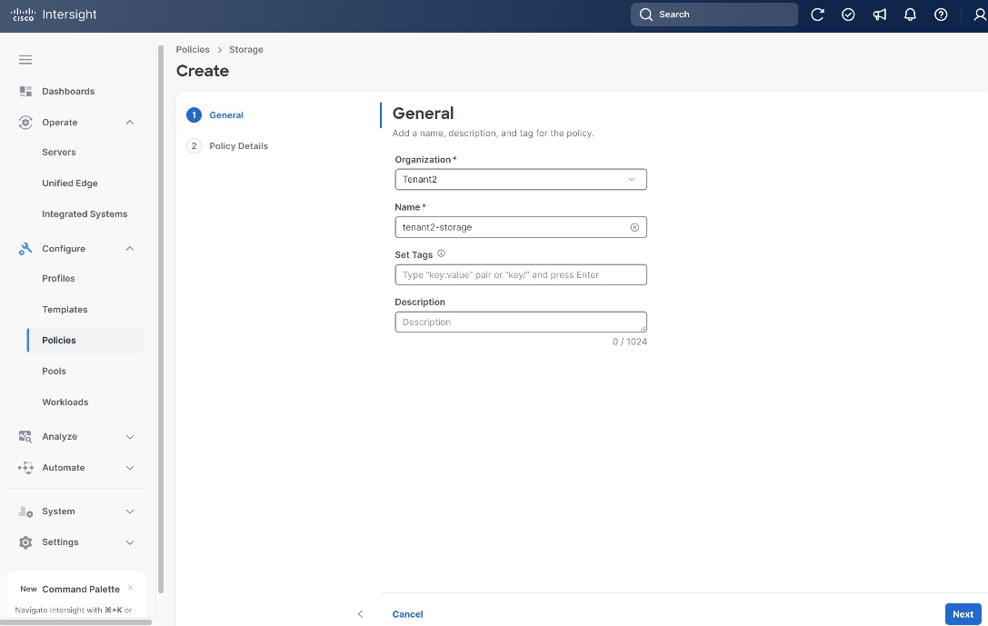
Step 8. Click UCS Server (Unified Edge).
Step 9. Toggle the switch to enable M.2 RAID Configuration. Leave all fields at their default settings.
Step 10. Click Create.
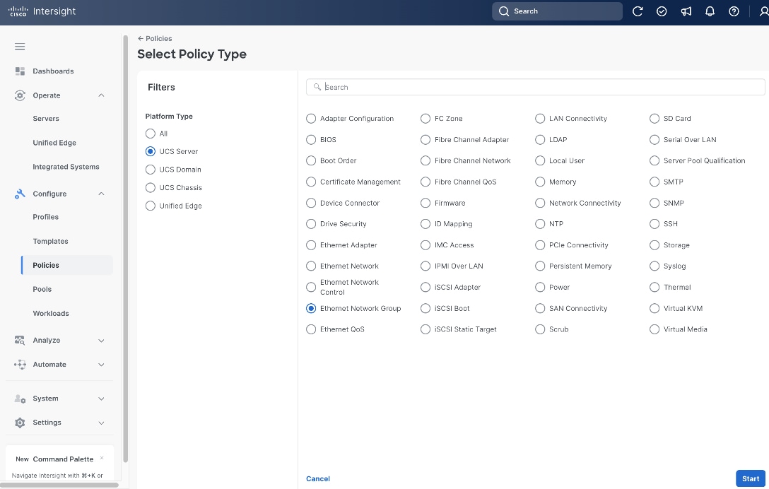
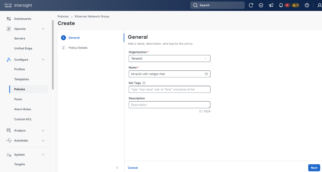
Procedure 10. Create Server Ethernet Network Group Policy
Step 1. Click Configure > Policies and then click Create Policy.
Step 2. On the Select Policy Type page, click UCS Server in the Filters section, then select Ethernet Network Group.
Step 3. Click Start.
Step 4. On the General page, select the correct Organization, for example, Tenant2.
Step 5. Provide a Name for the policy, for example, tenant2-eth-netgrp-rhel.
Step 6. (Optional) Provide Tags and Description.
Step 7. Click Next.
Step 8. On the Policy Details page, click UCS Server (Unified Edge).
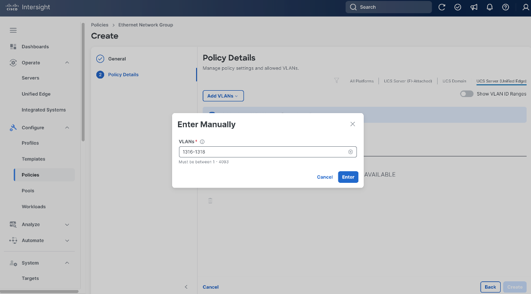
Step 9. From the Add VLANs drop-down list, choose Enter Manually.
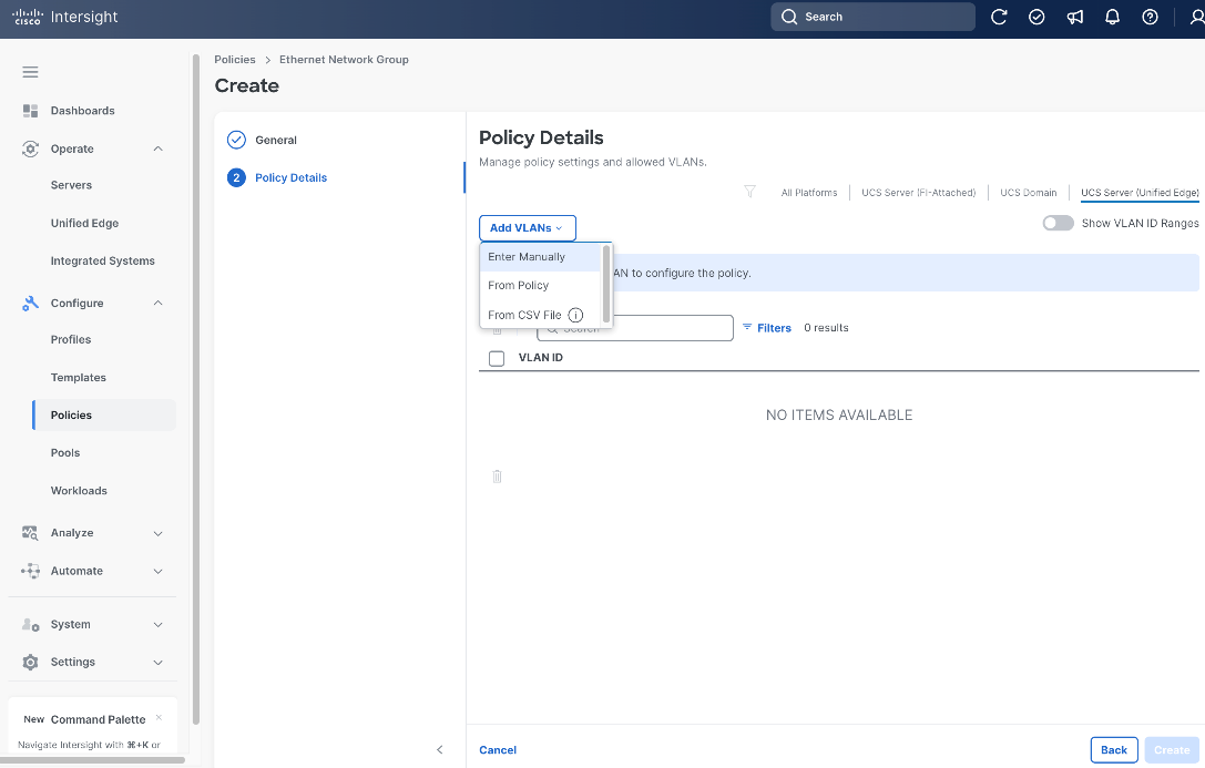
Step 10. Enter the VLAN range, for example, 1316-1318.
Step 11. Click Enter.
Step 12. From the Policy Details page, select the native VLAN ID, for example, 1316, click the ellipses (…) at the end of the row, then from the drop-down list, click Set Native VLAN.
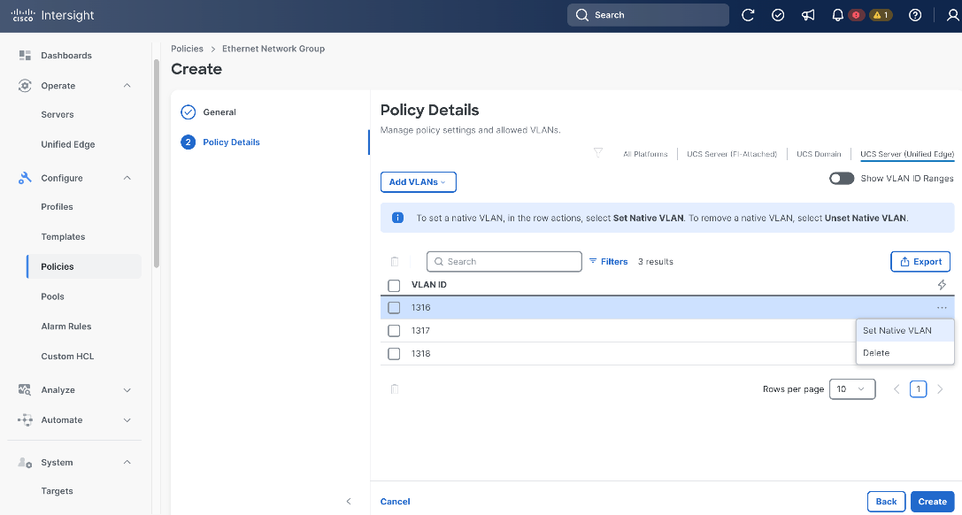
Step 13. Click Create.
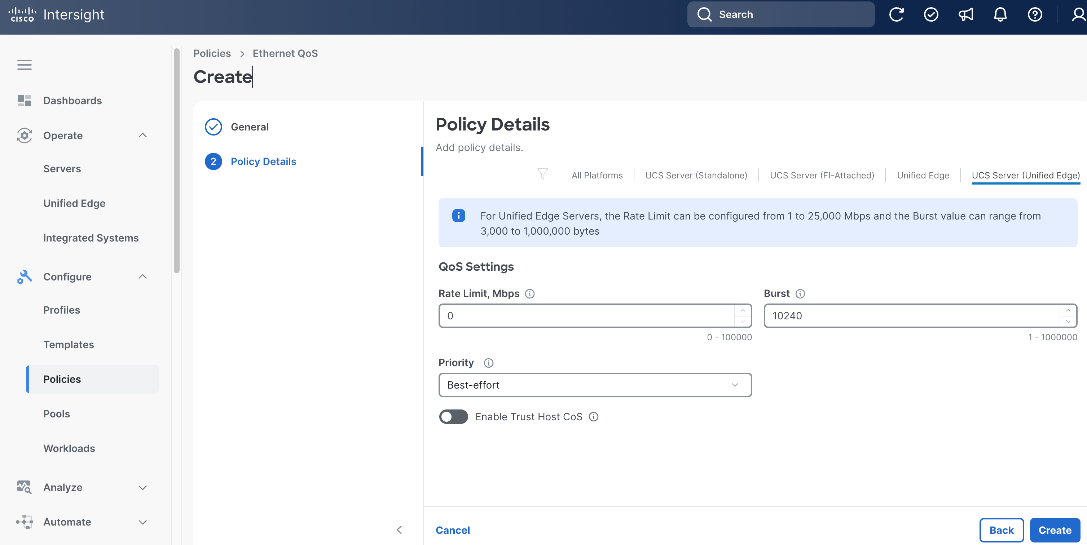
Procedure 11. Create Server Ethernet QoS Policy
Step 1. Click Configure > Policies and then click Create Policy.
Step 2. On the Select Policy Type page, click UCS Server in the Filters section, then select Ethernet QoS.
Step 3. Click Start.

Step 4. On the General page, select the correct Organization, for example, Tenant2.
Step 5. Provide a Name for the policy, for example, tenant2-eth-qos.
Step 6. (Optional) Provide Tags and Description.
Step 7. Click Next.
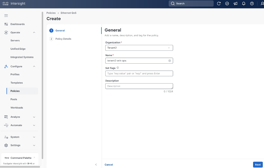
Step 8. On the Policy Details page, click UCS Server (Unified Edge).
Step 9. Leave all fields at their default settings, then click Create.
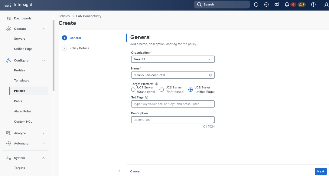
Procedure 12. Create Server LAN Connectivity Policy
Step 1. Click Configure > Policies and then click Create Policy.
Step 2. On the Select Policy Type page, click UCS Server in the Filters section, then select LAN Connectivity.
Step 3. Click Start.
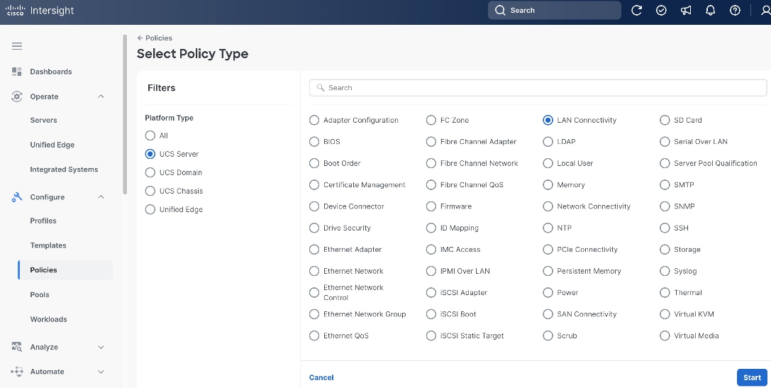
Step 4. On the General page, select the correct Organization, for example, Tenant2.
Step 5. Provide a Name for the policy, for example, tenant2-lan-conn-rhel.
Step 6. Set Target Platform to UCS Server (Unified Edge).
Step 7. (Optional) Provide Tags and Description.
Step 8. Click Next.
Step 9. On the Policy Details page, click Add vNIC.
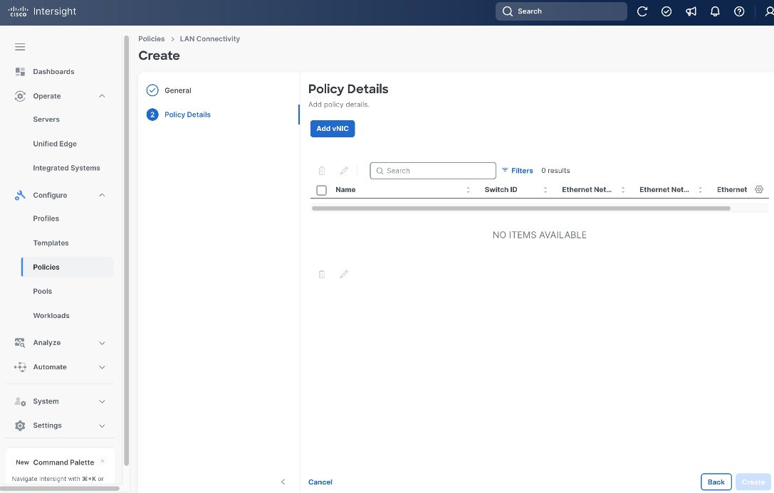
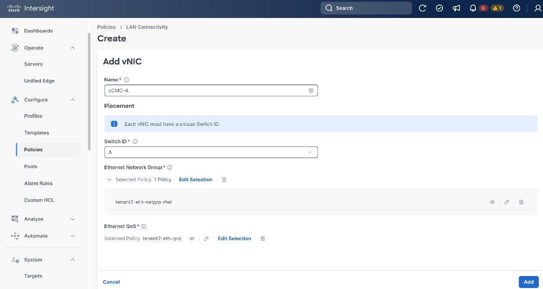
Step 10. On the Add vNIC page, provide the name, for example, eCMC-A.
Step 11. Select A as Switch ID.
Step 12. Select the Ethernet Network Group policy and Ethernet QoS policy we created in the previous steps, which are tenant2-eth-netgrp-rhel and tenant2-eth-qos, respectively.
Step 13. Click Add.
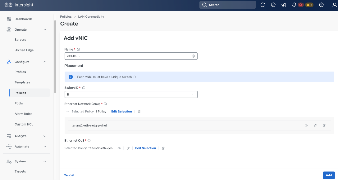
Step 14. From the Policy Details page, click Add vNIC.
Step 15. On the Add vNIC page again, provide a different name from the previous step, for example, eCMC-B.
Step 16. Select B as Switch ID.
Step 17. Select the Ethernet Network Group policy and Ethernet QoS policy we created in the previous steps, which are tenant2-eth-netgrp-rhel and tenant2-eth-qos, respectively.
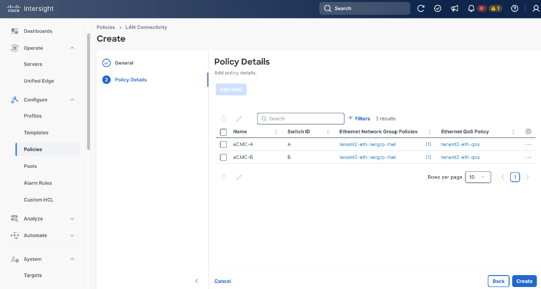
Step 18. Click Add.
Step 19. From the Policy Details page, click Create.
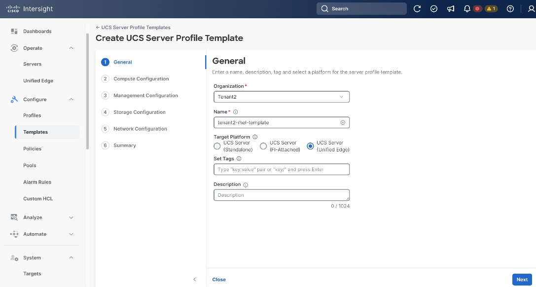
Procedure 13. Create Server Profile Templates
Step 1. Click Configure > Templates.
Step 2. On the Templates page, click UCS Server Profile Templates, then click Create UCS Server Profile Template.
Step 3. On the General page, select the correct Organization, for example, Tenant2.
Step 4. Provide a Name for the template, for example, tenant2-rhel-template.
Step 5. Set UCS Server (Unified Edge) as the Target Platform
Step 6. (Optional) Provide Tags and Description.
Step 7. Click Next.
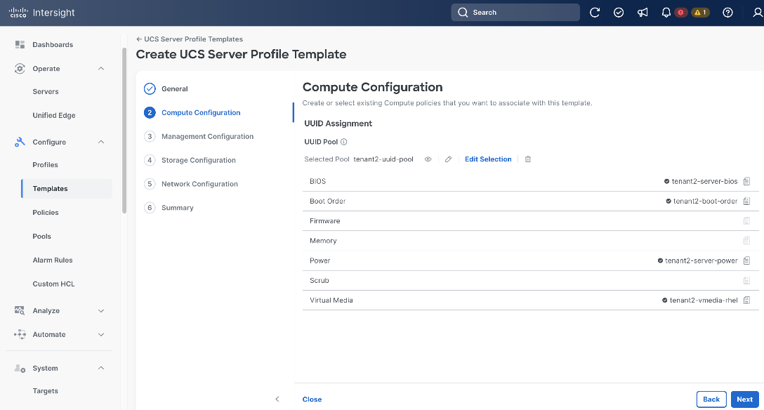
Step 8. On the Compute Configuration page, in UUID Pool section, click Select Pool, and choose the UUID pool created in the previous step, which is tenant2-uuid-pool.
Step 9. Click Select Policy next to BIOS. Select the BIOS policy created in the previous step, for example, tenant2-server-bios.
Step 10. Click Select Policy next to Boot Order. Select the Boot Order policy created in the previous step, for example, tenant2-boot-order.
Step 11. Click Select Policy next to Power. Select the Power policy created in the previous step, for example, tenant2-server-power.
Step 12. Click Select Policy next to Virtual Media. Select the Virtual Media policy created in the previous step, for example, tenant2-vmedia-rhel.
Step 13. Click Next.
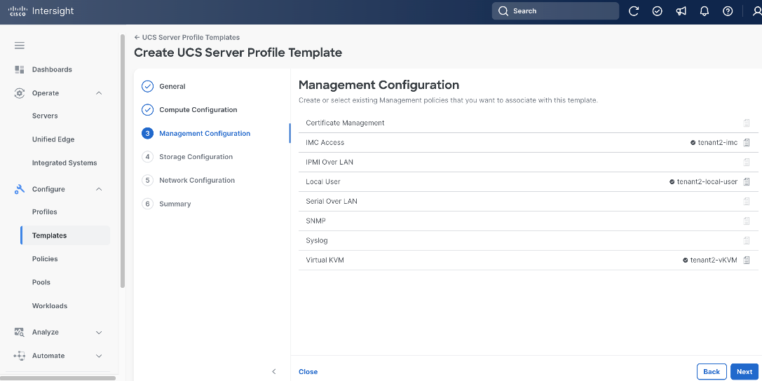
Step 14. On the Management Configuration page, click Select Policy next to IMC Access. Select IMC Access policy created in the previous step, for example, tenant2-imc.
Step 15. Click Select Policy next to Local User. Select the Local User policy created in the previous step, for example, tenant2-local-user.
Step 16. Click Select Policy next to Virtual KVM. Select the Virtual KVM policy created in the previous step, for example, tenant2-vKVM.
Step 17. Click Next.
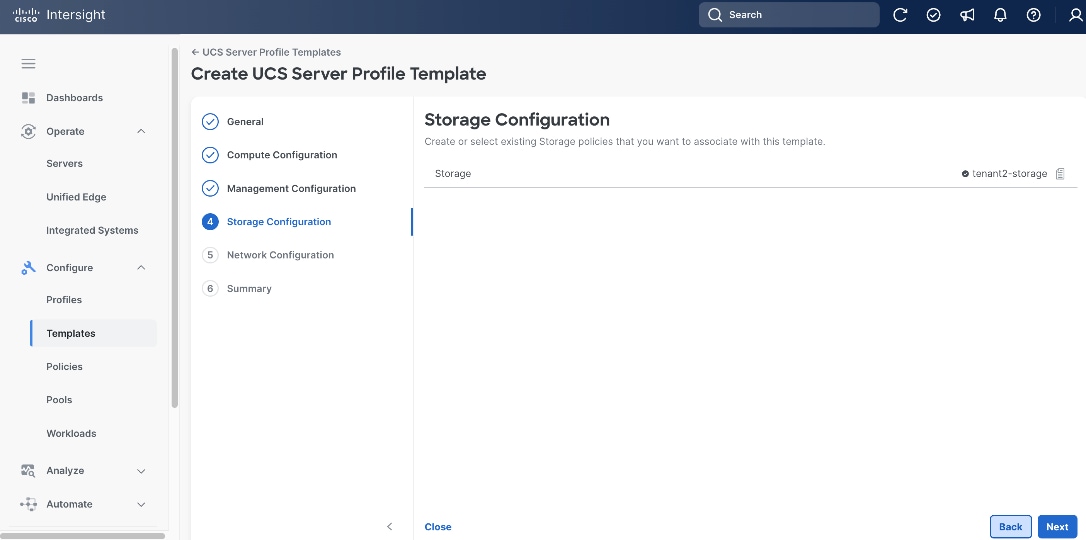
Step 18. On the Storage Configuration page, click Select Policy next to Storage. Select Storage policy created in the previous step, for example, tenant2-storage.
Step 19. Click Next.
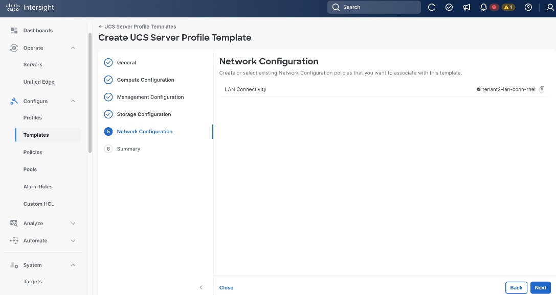
Step 20. On the Network Configuration page, click Select Policy next to LAN Connectivity. Select the LAN Connectivity policy created in the previous step, for example, tenant2-lan-conn-rhel.
Step 21. Click Next.
Step 22. On the Summary page, click Derive Profile.
Provision Servers
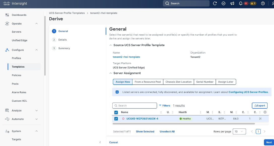
Procedure 1. Derive and Apply Server Profile
Step 1. On the General page, select the server you want to assign to the server profile.
Step 2. Click Next.
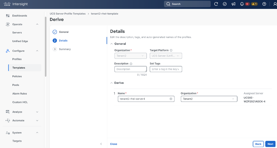
Step 3. On the Details page, provide Name, for example, tenant2-rhel-server4, and make sure the Organization is set to the right value, for example, Tenant2.
Step 4. (Optional) Provide Tags and Description.
Step 5. Click Next.
Step 6. On the Summary page, click Derive.
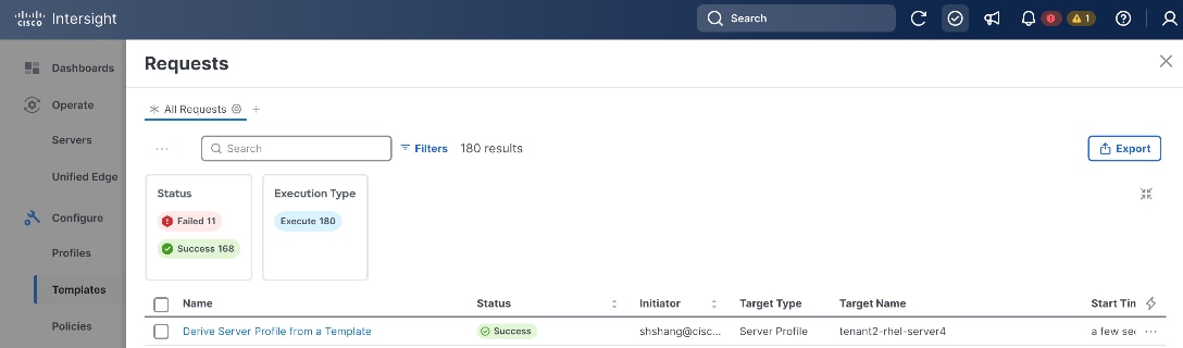
Step 7. Click the checkmark icon at the upper-right corner to monitor the status of profile creation request. It will take a few minutes for the request Derive Server Profile from a Template to reach the Success status.
Procedure 2. Apply Server Profile
Step 1. Click Configure > Profiles.
Step 2. On the Profiles page, select the UCS Server Profiles.
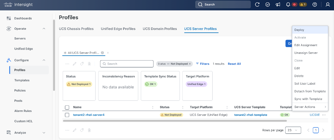
Step 3. Select a profile created in the previous step. Click the ellipses (…) at the end of the row, then click Deploy from the drop-down list.
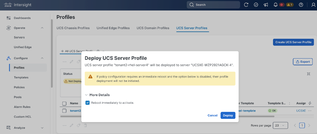
Step 4. In the pop-up window, click Reboot immediately to activate, then click Deploy.
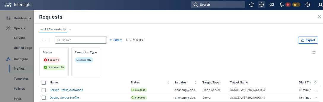
Step 5. Click the checkmark icon at the upper-right corner to monitor the status of server profile deployment request. It will take a while for the requests Deploy Server Profile and Server Profile Activation to reach Success status.
Step 6. Go to Operate > Servers. Verify the Health status for the server is Healthy.
Procedure 3. Enable Tunnel vKVM (Optional)
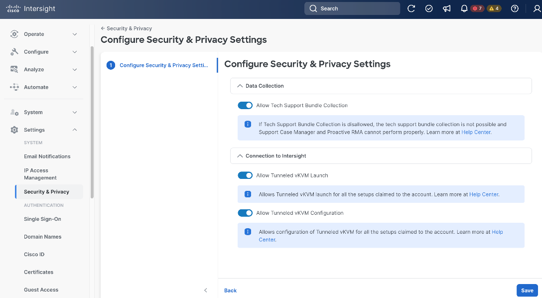
Step 1. Go to Settings > Security & Privacy, then click Configure.
Step 2. On the Configure Security & Privacy Settings page, in Connection to Intersight section, toggle the switch to enable Allow Tunneled vKVM Launch and Allow Tunneled vKVM Configuration.
Step 3. Click Save.
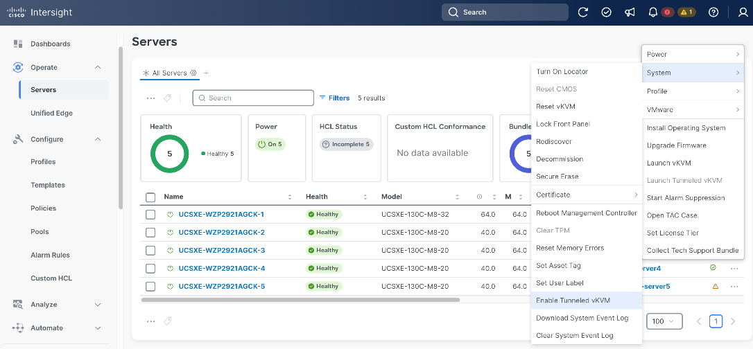
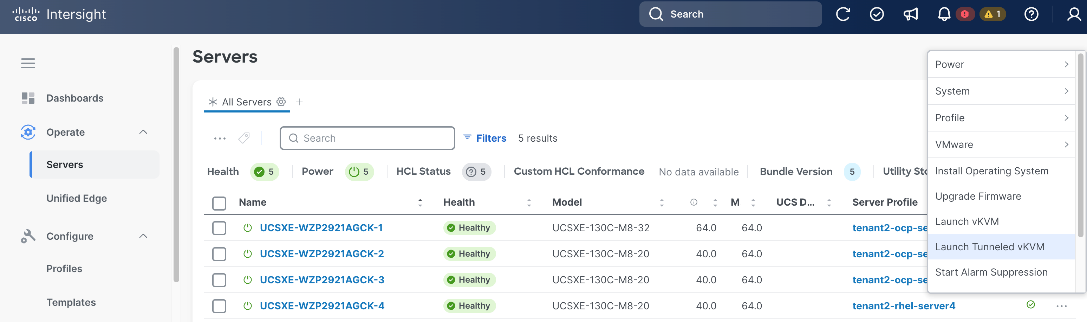
Step 4. Go to Operate > Servers, select the server and then click the ellipses (…) at the end of the row. From the drop-down list, select System > Enable Tunneled vKVM.
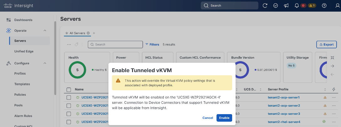
Step 5. In the pop-up window, click Enable.
Step 6. Go to Operate > Servers, select the server and then click the ellipses (…) at the end of the row. From the drop-down list, select Launch Tunneled vKVM.
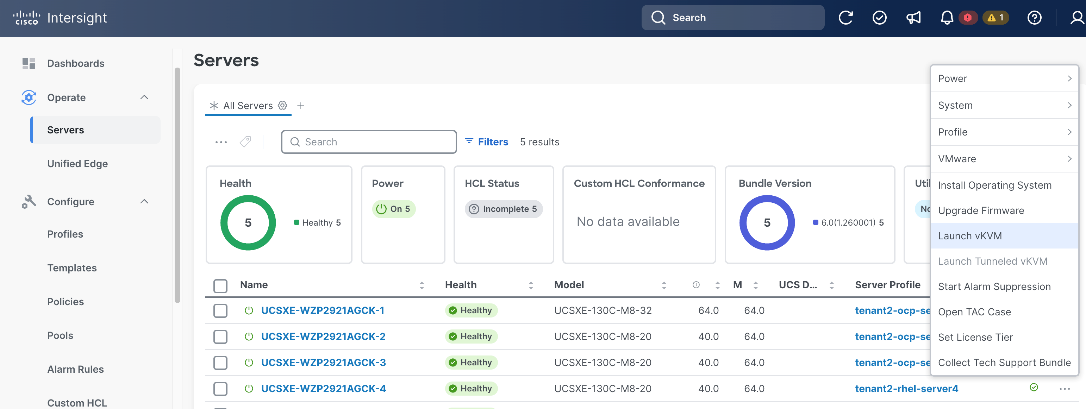
Install and Configure RHEL Using Cisco Intersight vKVM / Tunneled KVM
This section describes the deployment procedures for installing Red Hat Enterprise Linux (RHEL) 9.6 on the Cisco Unified Edge platform using vKVM or Tunneled KVM console access via Cisco Intersight. The installation uses the standard RHEL interactive installer, which provides a straightforward graphical workflow for configuring storage, networking, and system settings. This approach is recommended for users who prefer a guided, interactive installation experience with real-time feedback and minimal manual configuration.
The deployment process begins with the RHEL base OS installation, then progressively builds the required workload infrastructure. Networking is finalized after first boot using NetworkManager (nmcli), followed by activation of the RHEL subscription and system updates. Podman and container tools are then installed to support containerized workloads, and KVM with libvirt is configured to enable virtual machine hosting directly on the RHEL host.
Installation Flow:
● Install RHEL 9.6 base OS via vKVM or Tunneled KVM using Cisco Intersight
● Configure post-boot networking: bond, VLAN, DHCP (NetworkManager/nmcli)
● Activate RHEL subscription and apply system updates
● Install Podman and container tools for containerized workload support
● Install and configure KVM/libvirt for virtual machine hosting
● (Optional) Enable GPU support for NVIDIA L4 GPU-equipped systems
Prerequisites
DNS Entries
The following domain and hostname are used in this deployment guide:
● Base Domain: tenant2.avatar.local
● RHEL Hostname: rhel
The fully qualified domain name (FQDN) for the RHEL host is the hostname followed by the base domain, for example, rhel.tenant2.avatar.local.
Prior to initiating the RHEL installation, ensure the DNS entries shown in Table 5 are configured on your DNS server.
A reverse DNS entry for the RHEL host IP address must also be configured to map back to its hostname. This ensures proper hostname resolution during and after installation.
Table 5. DNS FQDN Names Used for RHEL server
| DNS Name |
IP Address |
Note |
| rhel.tenant2.avatar.local |
10.131.7.104 |
Points to the RHEL host IP address, used for host management and remote SSH access |
SSH Key
Before proceeding with the RHEL installation, it is recommended to generate an SSH key pair on your local machine or workstation. The SSH key pair consists of a private key (which you retain securely) and a public key (which can be added to the RHEL host after installation). The public key can be placed in the authorized_keys file of the admin or root user, enabling secure passwordless SSH access to the RHEL host for troubleshooting, maintenance, and administrative tasks.
Procedure 1. Obtain MAC addresses
Obtain the MAC addresses of the two interfaces from the UCS Server Profile for the RHEL host. The MAC addresses will be used during post-boot network configuration to correctly map physical NIC device names to their intended bond roles (primary and backup).
Step 1. Log in to Cisco Intersight
Step 2. Go to Operate > Servers, click the server you want to install RHEL on.
Step 3. Click the Inventory tab, go to Network Adapters > Adapter LOM-NIC-1, then click the Interfaces tab.
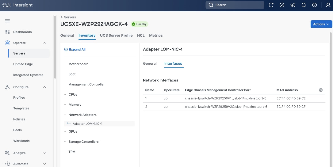
Step 4. Write down the MAC addresses for network interface 1, which is associated with chassis-1/switch-WZP29259V1L/slot-1/muxhostport-6, and network interface 2, which is associated with chassis-1/switch-WZP29259V2C/slot-1/muxhostport-6. These values will be used to identify the physical NIC device names during post-boot network configuration:
● Network Interface 1 MAC =
● Network Interface 2 MAC =
Note: The chassis and switch identifiers shown in the interface associations (e.g., chassis-1/switch-WZP29259V1L/slot-1/muxhostport-6) are examples from this deployment and will differ in your environment.
Procedure 2. Insert Installation Media
Before launching the RHEL installer, mount the RHEL 9.6 installation ISO image to the server using the Cisco Intersight Virtual Media policy. This makes the ISO image available as a virtual DVD drive that the server can boot from during the installation process.
Step 1. Log in to Cisco Intersight.
Step 2. Go to Configure > Policies, click the Virtual Media policy used by RHEL profile, for example, tenant2-vmedia-rhel.
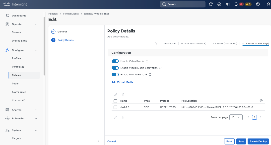
Step 3. On the Policy Details page, click the UCS Server (Unified Edge) tab at the upper-right corner, then click Add Virtual Media.
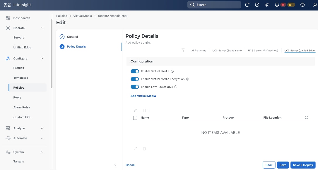
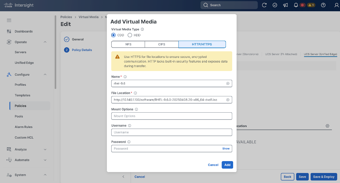
Step 4. In the Add Virtual Media page, choose CDD as Virtual Media Type, click HTTP/HTTPS option. Provide the Name of the media, for example, rhel-9.6, and the URL to the ISO image in File Location. Then click Add.
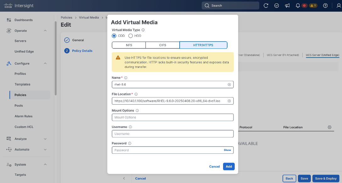
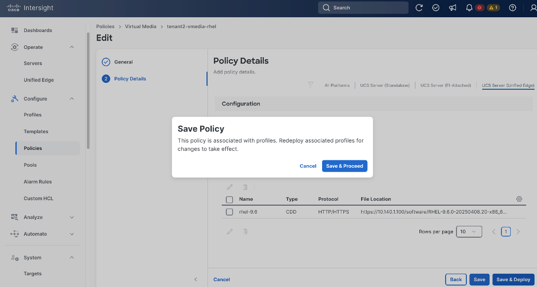
Step 5. Back to the Policy Details page, click Save & Deploy.
Step 6. On Save Policy window, click Save & Proceed.
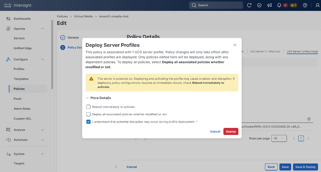
Step 7. On Deploy Server Profiles window, select I understand that potential disruption may occur during profile deployment, then click Deploy.
Procedure 3. Install Red Hat Enterprise Linux
This procedure assumes:
● Cisco Intersight server configuration and provisioning are already complete
● The server boots in UEFI mode
● RHEL 9.6 installation media is available through vKVM or Tunneled KVM
● The target boot disk is the 450 GB MSTOR-RAID (M.2-Hwraid) disk
● The 1.8 TB NVMe disk must remain unused after installation
● The network requirements are:
◦ bond0 in active-backup mode
◦ primary NIC = MAC EC:F4:0C:FD:B9:CE
◦ backup NIC = MAC EC:F4:0C:FD:B9:CF
◦ VLAN subinterface = bond0.1317
◦ DHCP on bond0.1317
◦ NTP server = 10.81.254.202
Step 1. In Cisco Intersight, go to Operate > Servers in the left panel.
Step 2. Select the target server and click the ellipses (…) at the end of the row. From the drop-down list, click Launch Tunneled vKVM.
Step 3. In the Tunnel vKVM window, click Virtual Media on the left and verify RHEL 9.6 ISO image is mounted.
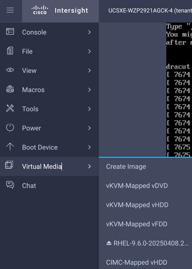
Step 4. Click Boot Device from the left, click CIMC-Mapped DVD.
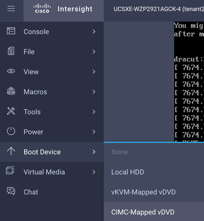
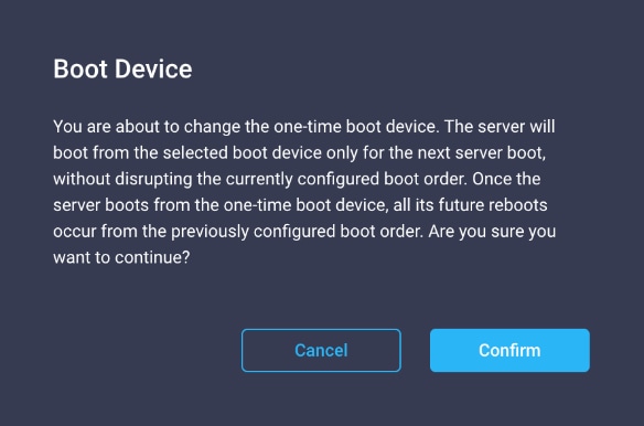
Step 5. In the confirmation window, click Confirm.
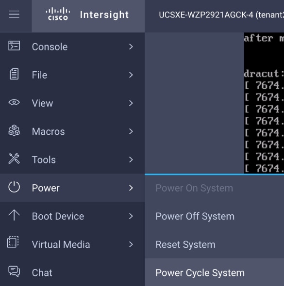
Step 6. Click Power on the left and select Power Cycle System.
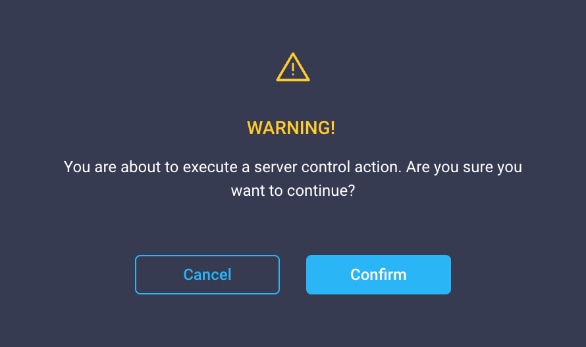
Step 7. In the confirmation window, click Confirm.
After server boots up, you should see the RHEL interactive installation UI.
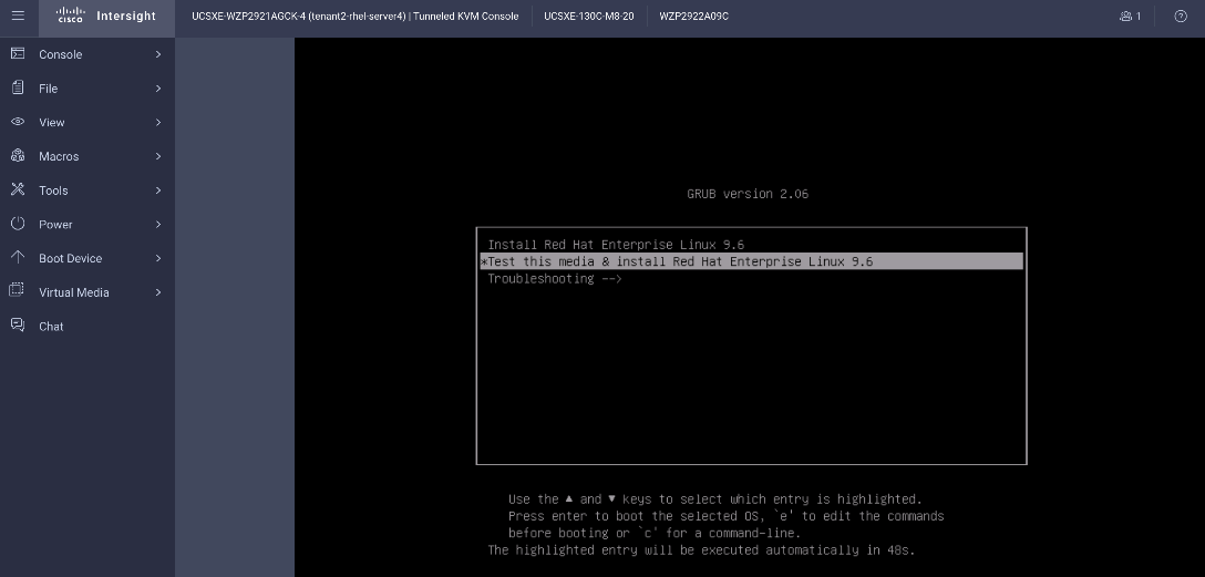
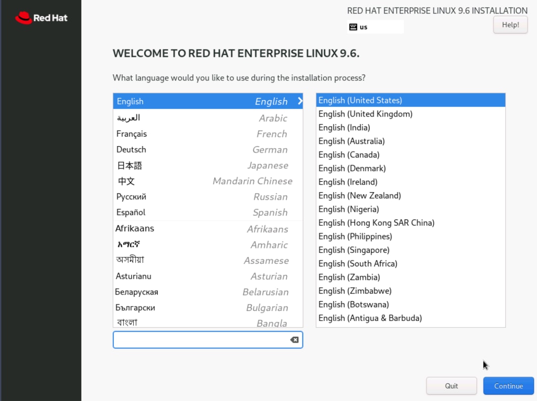
Step 8. Choose your preferred language, for example, English (United States). Click Continue.
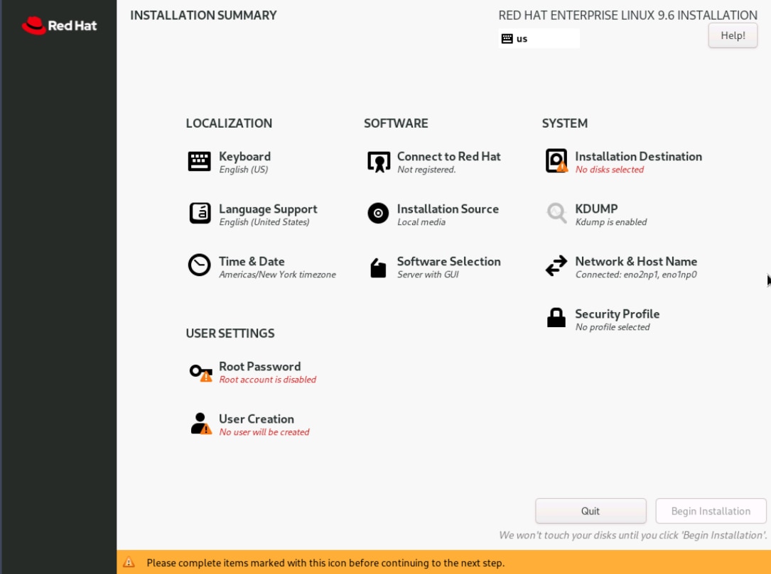
Step 9. On Installation Summary page, click Installation Destination in SYSTEM section.
Step 10. Keep only the 447.07 GiB ATA CISCO VD (sda) disk selected. This is the 450 GB MSTOR-RAID (M.2-Hwraid) disk referenced in the prerequisites. The size difference between 450 GB and 447.07 GiB is due to binary vs. decimal unit conversion. Leave 1.75 TiB KIOXIA ... (nvme0n1) unselected. Keep Automatic selected under Storage Configuration. Click Done.
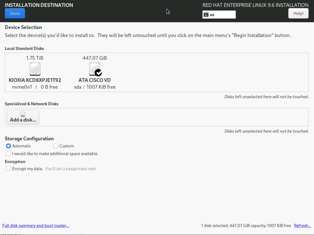
Note: Because the system is booting in UEFI mode, the installer creates the required UEFI boot structures on the selected installation disk when automatic partitioning is used.
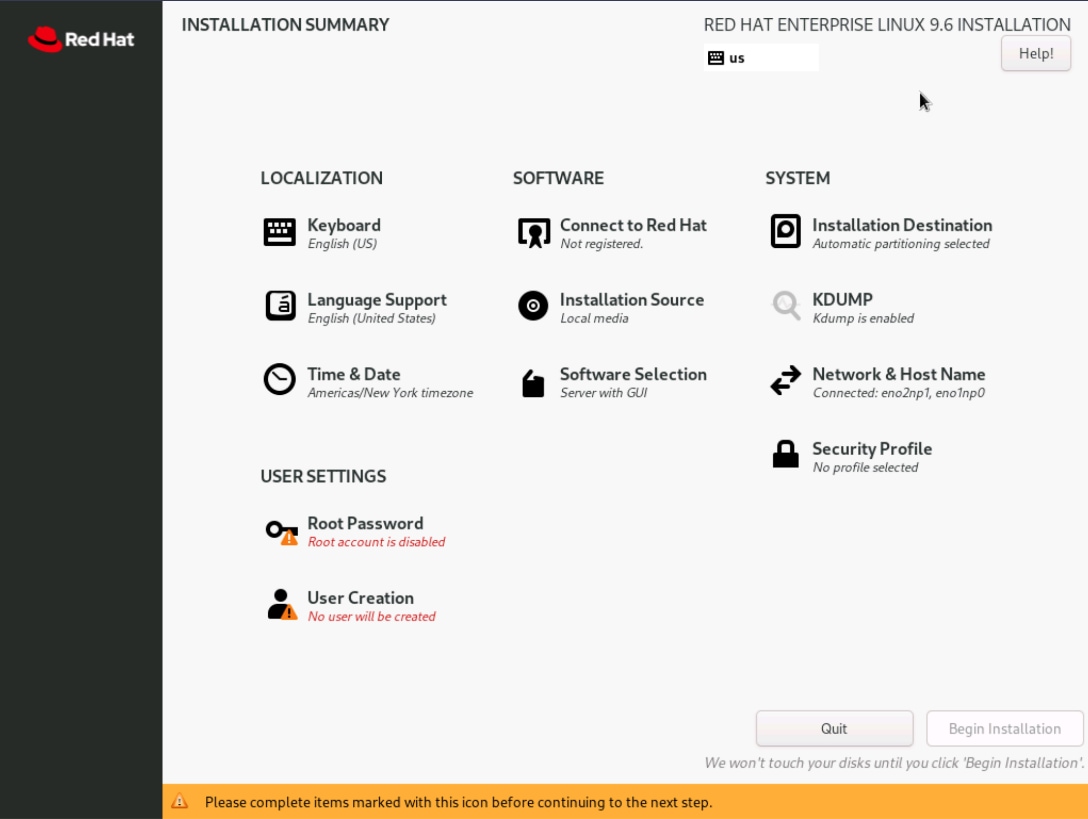
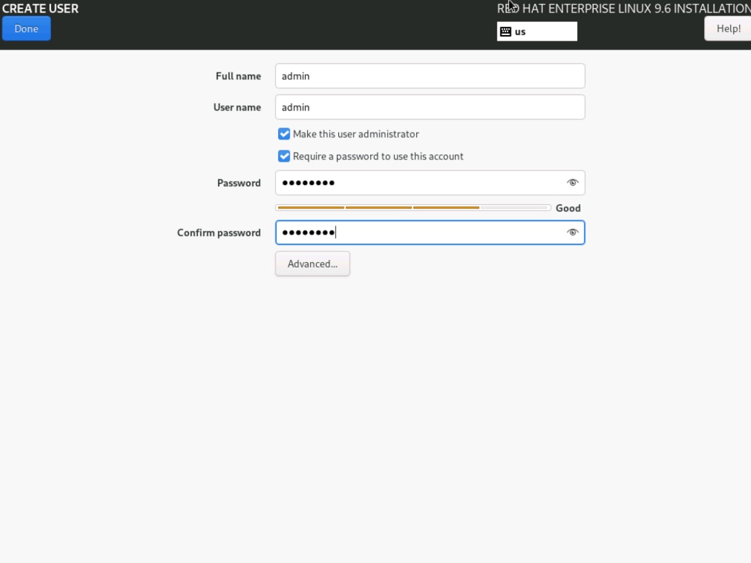
Step 11. Click User Creation in USER SETTINGS section. Create a non-root user, for example, admin. Click Done.
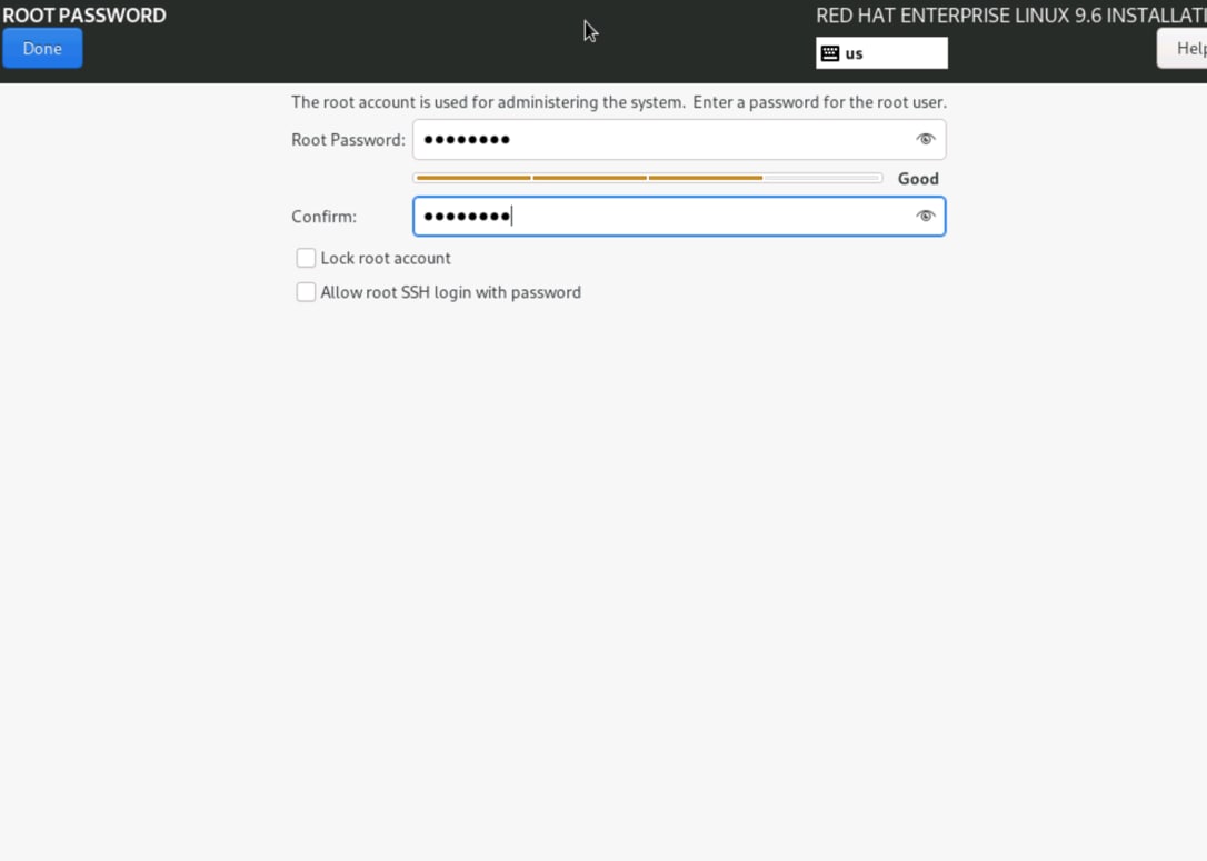
Step 12. Select Root Password in USER SETTINGS section and set the root password. Click Done.
Note: Skip network configuration entirely and continue with local-media install. Network configuration will be completed post-boot using NetworkManager (nmcli) as described in the procedure Add RHEL network configuration.
Step 13. Review any remaining installation items. Click Begin Installation.
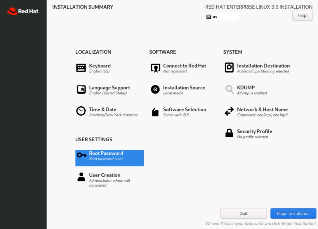
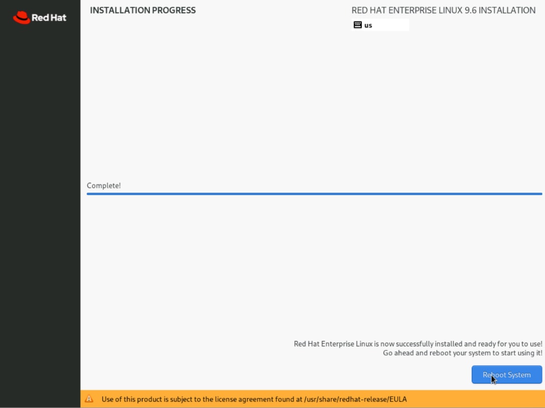
Step 14. When installation finishes, click Reboot System.
Step 15. Remove or disconnect the installation media from Virtual Media drop-down list on Tunnel vKVM.

Step 16. After server boots up, log in to RHEL 9.6 as the non-root user.
Procedure 4. Add RHEL network configuration
After the system boots from the 450 GB MSTOR-RAID disk, configure the required network settings. RHEL 9 supports configuring bonds with nmcli, and VLAN interfaces can be created on top of a bond.
Based on the design recommendation in CVD, target end state is shown below:
● bond0 in active-backup mode
● primary NIC: NIC has MAC address equal to
● backup NIC: NIC which has MAC address equal to
● primary_reselect = always
● no IPv4 or IPv6 address on the two physical NICs and bond0
● IPv4 on VLAN interface bond0.1317 by DHCP. IPv6 disabled on bond0.1317
Step 1. Open a terminal session on the RHEL host. All network configuration commands in this section must be run from the terminal as the admin user. Use sudo where indicated.
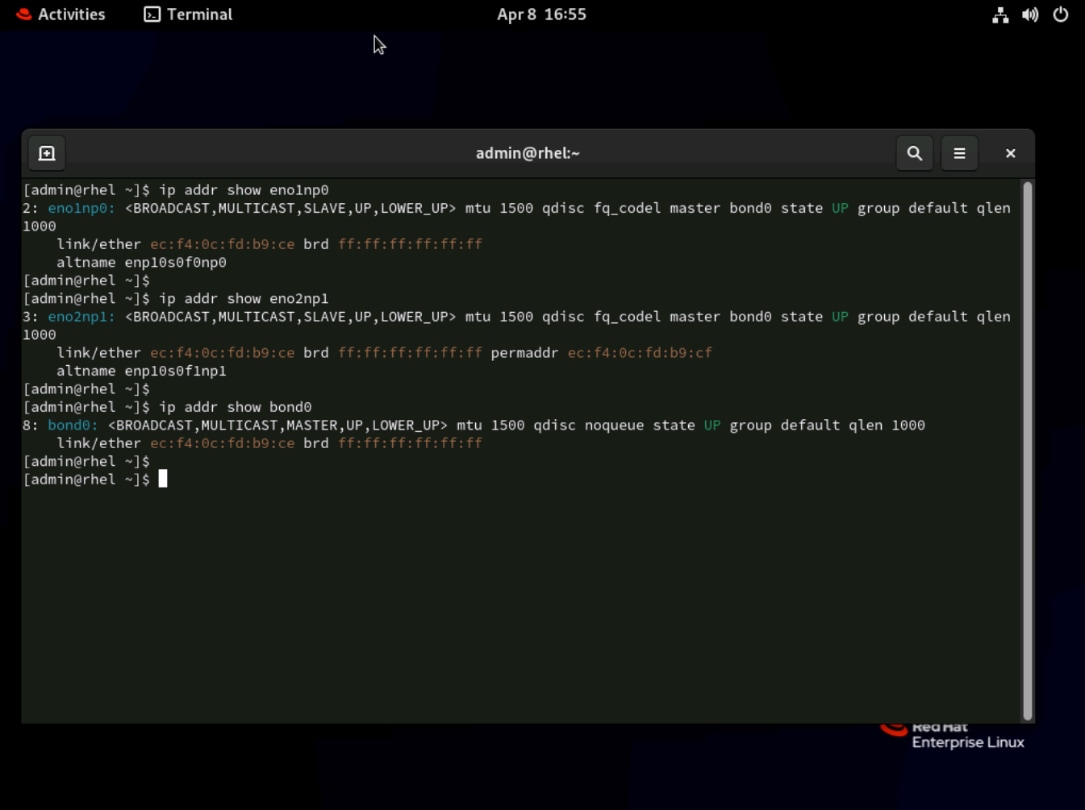
Step 2. Identify the Linux device names that match the two NIC MAC addresses
Step 3. Use the following command to list all network interfaces and their associated MAC addresses. Match the output against the two MAC addresses you recorded from Cisco Intersight to identify the correct device names for the primary and backup NICs:
nmcli -g GENERAL.DEVICE,GENERAL.HWADDR device show
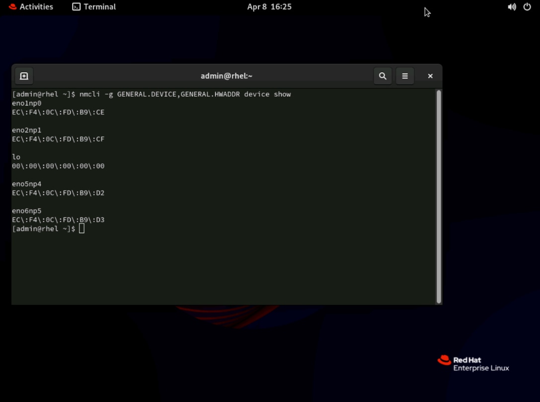
Step 4. Map the installed NIC device names to the two MAC addresses. Record the interface names that match <NODE-NIC1-MAC> as <nic_primary> and <NODE-NIC2-MAC> as <nic_backup>:
In this example,
● EC:F4:0C:FD:B9:CE -> eno1np0, which is the primary NIC
● EC:F4:0C:FD:B9:CF -> eno2np1, which is the backup NIC
Step 5. Create the bond interface.
Create the bond0 interface in active-backup mode using the following command. The primary option designates the preferred active interface, and primary_reselect=always ensures the primary NIC is reactivated as soon as it recovers. IPv4 and IPv6 are intentionally disabled on the bond itself because the IP address will be assigned to the VLAN subinterface bond0.1317 in a later step.
nmcli connection add type bond ifname bond0 con-name bond0 \
bond.options "mode=active-backup,primary=eno1np0,primary_reselect=always" \
ipv4.method disabled ipv6.method disabled
Step 6. Add the two NICs as bond members.
Add the primary and backup NIC as bond ports. This keeps both physical NICs as bond members only, with no IPv4 or IPv6 address assigned directly to them.
nmcli connection add type ethernet ifname eno1np0 con-name bond0-slave-primary master bond0
nmcli connection add type ethernet ifname eno2np1 con-name bond0-slave-backup master bond0
Step 7. Create the VLAN subinterface.
Create VLAN subinterface bond0.1317 on top of bond0. This subinterface is configured to obtain its IP address automatically via DHCP. IPv6 is disabled in this design.
nmcli connection add type vlan ifname bond0.1317 con-name bond0.1317 dev bond0 id 1317 ipv4.method auto ipv6.method disabled
Step 8. Bring up the connections.
Activate all four connection profiles in the following order. The bond interface must be brought up before its member NICs, and the VLAN subinterface must be activated last to ensure it inherits a working bond as its parent.
nmcli connection up bond0
nmcli connection up bond0-slave-primary
nmcli connection up bond0-slave-backup
nmcli connection up bond0.1317
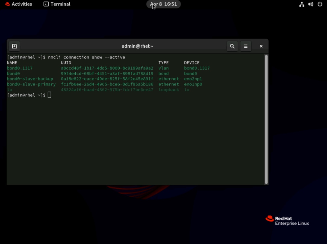
Step 9. Verify that all four connection profiles are active by running the following command. The output should show bond0, bond0-slave-primary, bond0-slave-backup, and bond0.1317 all listed. Any missing profile indicates an activation failure that must be resolved before continuing.
nmcli connection show --active
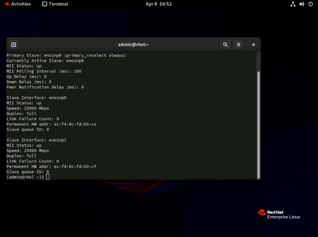
Step 10. Inspect the kernel bonding state file to confirm that the bond is operating correctly. This file is the authoritative source for live bonding status in the Linux kernel and reflects the actual hardware state.
cat /proc/net/bonding/bond0
Confirm that:
● Bonding Mode is active-backup
● Primary Slave is
● The second Slave Interface is
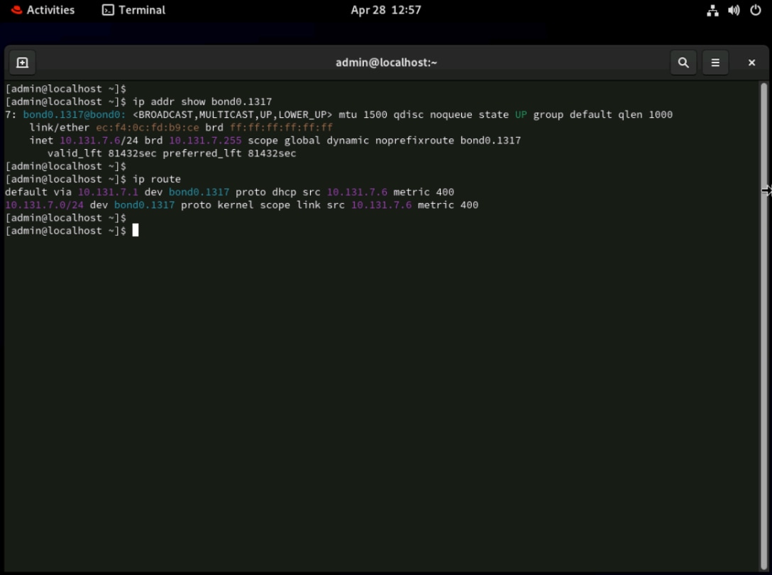
Step 11. Verify that the VLAN subinterface has received a DHCP address and that the default route is correctly set.
ip addr show bond0.1317
ip route
Confirm:
● bond0.1317 exists
● It has an IPv4 address from DHCP
● The default route uses bond0.1317
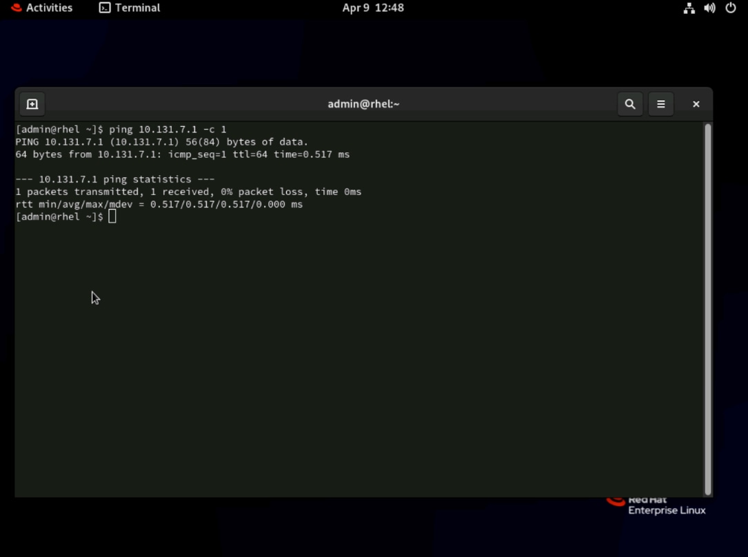
Step 12. Send a single ping to the default gateway to confirm end-to-end Layer 3 connectivity through the bond and VLAN stack. A successful reply confirms that the physical NICs, bond interface, VLAN subinterface, and upstream switch configuration are all working correctly.
ping 10.131.7.1 -c 1
Step 13. Confirm that neither the physical NICs nor the bond0 interface have been assigned IP addresses. In this design, all IP traffic must flow exclusively through bond0.1317. An IP address appearing on any of these three interfaces would indicate a misconfiguration that could cause routing conflicts.
ip addr show <nic_primary>
ip addr show <nic_backup>
ip addr show bond0
Confirm:
● Neither physical NIC has an IPv4 or IPv6 address
● bond0 has no IPv4 or IPv6 address
● Only bond0.1317 has the DHCP IPv4 address
Procedure 5. Activate RHEL subscription
Step 1. Register the RHEL host with Red Hat Subscription Management using one of the two methods below. Use the activation key method (Option A) for automated or scripted deployments where embedding credentials is undesirable. Use the username and password method (Option B) for interactive or ad-hoc registrations.
sudo rhc connect --activation-key <key> --organization <org>
OR
sudo rhc connect --username <username> --password <password>
Procedure 6. Refresh metadata and upgrade installed RHEL packages
Step 1. Check for available updates without applying them. This step allows you to review pending updates, including any kernel security patches, before committing to the upgrade.
sudo dnf check-update
Step 2. Apply all available updates to bring the system to a current, supported baseline. This may result in a new kernel version.
sudo dnf update -y
Note: dnf update can move a RHEL host to the latest available minor release within the same major RHEL 9 version unless the system is pinned/release-locked or using constrained repos.
Step 3. Check installed kernels and running kernel.
rpm -q kernel
uname -r
What to look for:
● The command rpm -q kernel shows the installed kernel package level
● The command uname -r shows the currently running kernel
The sample output is shown below:
$ rpm -q kernel
kernel-5.14.0-570.12.1.el9_6.x86_64
kernel-5.14.0-611.47.1.el9_7.x86_64
$ uname -r
5.14.0-570.12.1.el9_6.x86_64
Step 4. If a new kernel package appears in the output of rpm -q kernel that does not match the output of uname -r, reboot the system to activate the new kernel. Skip reboot only if no new kernel packages were installed.
sudo reboot
IMPORTANT! After reboot, both NICs are renamed to eno1 and eno2 and in disconnected status. There is NO network connectivity. Therefore, perform the next procedure, Reconfigure Network Interfaces, from the Tunneled vKVM session.
Procedure 7. Reconfigure Network Interfaces
Step 1. Check the network devices and connections:
nmcli device status
nmcli connection show
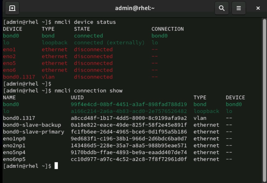
The nmcli device status command shows the new interface names, such as eno1, eno2, eno5 and eno6.
In the output of nmcli connection show command, you should still see:
● The bond0 connection profile remains present
● The ethernet profiles, eno1np0 and eno2np1, have DEVICE column as --
Step 2. Update the bond member profiles to use the new interface names assigned after reboot, such as eno1 and eno2. The first two commands update the interface name binding for each profile. The next two commands clear the previously recorded MAC address from each profile, which prevents NetworkManager from rejecting the profile if the MAC does not match the renamed interface. The final three commands reload the configuration and bring all connections back online.
sudo nmcli connection modify "bond0-slave-primary" connection.interface-name eno1
sudo nmcli connection modify "bond0-slave-backup" connection.interface-name eno2
sudo nmcli connection modify "bond0-slave-primary" 802-3-ethernet.mac-address ""
sudo nmcli connection modify "bond0-slave-backup" 802-3-ethernet.mac-address ""
sudo nmcli connection reload
sudo nmcli connection up "bond0-slave-primary"
sudo nmcli connection up "bond0-slave-backup"
sudo nmcli connection up "bond0.1317"
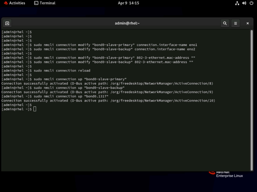
Step 3. Run the following verification commands to confirm that network connectivity has been successfully restored after the interface rename.
nmcli device status
cat /proc/net/bonding/bond0
ip address
ip route
ping 10.131.7.1 -c 1
Each command checks a different layer of the network stack:
● nmcli device status: Confirms all interfaces are in a connected state under NetworkManager.
● cat /proc/net/bonding/bond0: Confirms the kernel bonding driver shows the correct active and backup slaves.
● ip address: Provides a compact view of all interfaces and their IP addresses.
● ip route: Confirms the default route is pointing through bond0.1317.
● ping 10.131.7.1 -c 1: Confirms end-to-end Layer 3 connectivity to the gateway.
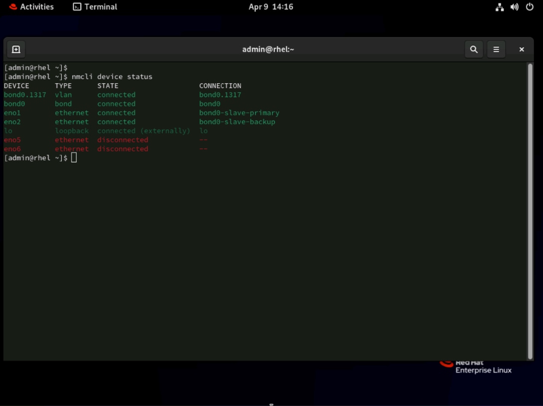
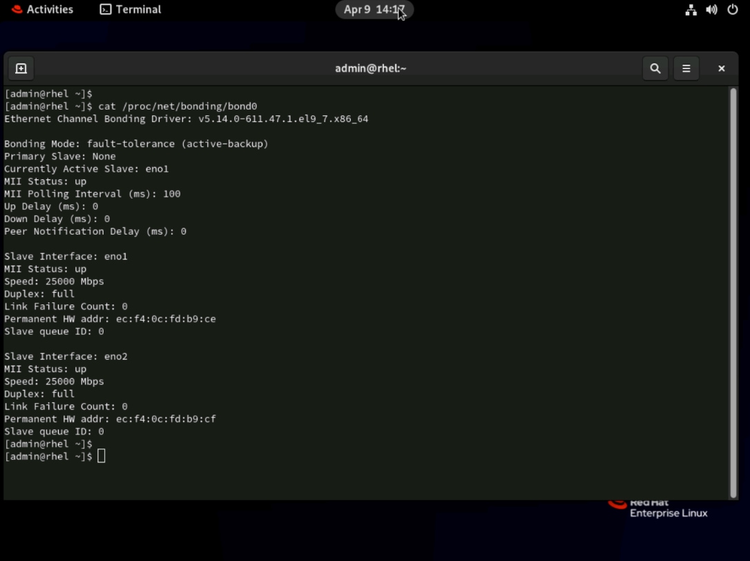
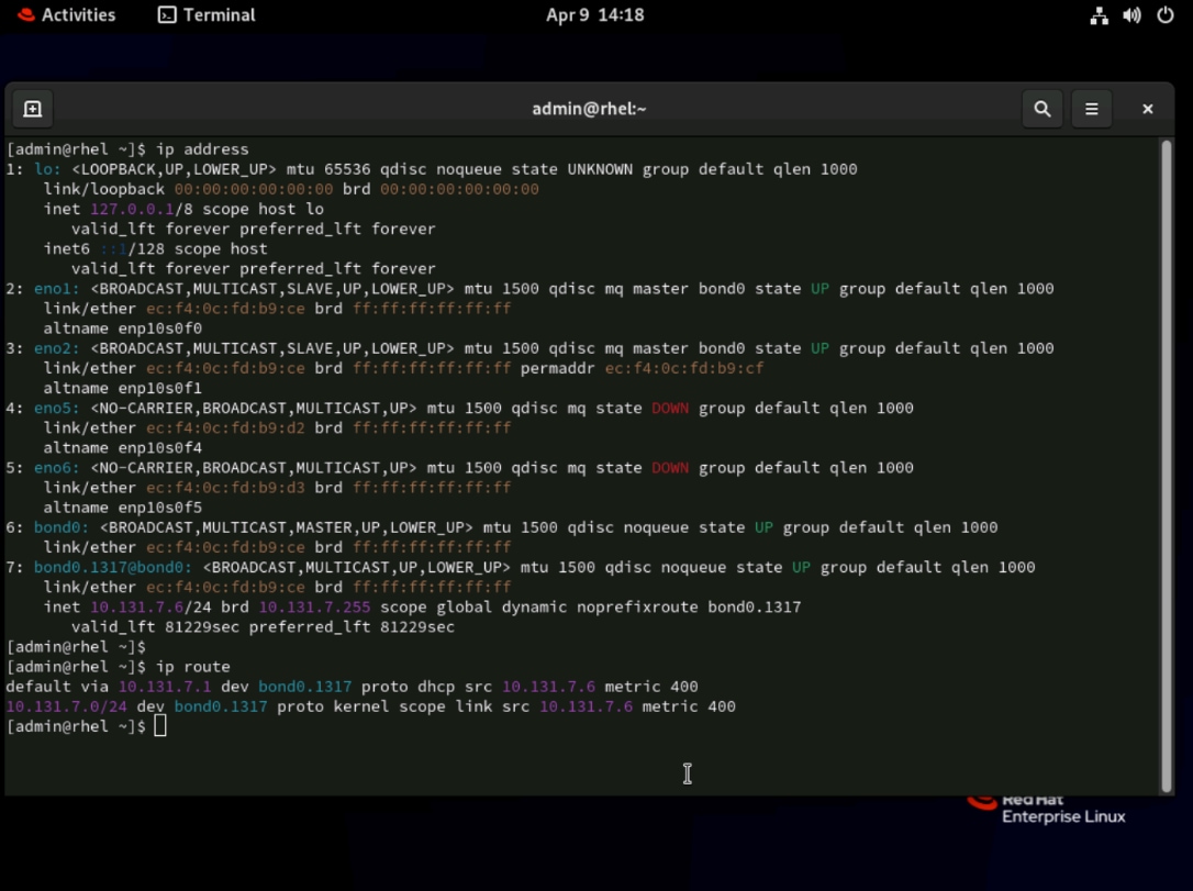
Step 4. Restart the RHEL by running the command sudo reboot and verify the change is persistent.
On RHEL 9, the recommended broader installation path is to install the container-tools meta-package, which includes Podman and related tools such as Buildah and Skopeo.
After the container tools are installed, the procedure verifies that Podman is working correctly by checking the installed versions, inspecting Podman runtime information, and running a simple test container. If web-based container management is also desired, the procedure then installs the RHEL web console (Cockpit) and the Podman plug-in, enables the Cockpit socket, opens firewall access if needed, and verifies that the web console can be used to view and manage the test container.
Procedure 1. Install Podman and container tools
Step 1. The container-tools meta-package is available on RHEL 9.6, and it includes Podman and related tools.
sudo dnf install -y container-tools
Verify that the Podman installation completed successfully by running the following commands:
● rpm -q container-tools confirms the meta-package is installed
● podman --version works and returns podman version
rpm -q container-tools
podman --version
$ rpm -q container-tools
container-tools-1-14.el9.noarch
$ podman --version
podman version 5.6.0
Note: The Podman version may vary depending on the RHEL 9 minor release and enabled repositories.
Step 2. Run the following command to create a test container as a user with root privilege:
sudo podman pull registry.access.redhat.com/ubi9/ubi-minimal
sudo podman run -d --name podman-ui-test registry.access.redhat.com/ubi9/ubi-minimal sleep infinity
sudo podman ps
sudo podman inspect podman-ui-test --format '{{.State.Status}}'
Success criteria:
● The image pull succeeds
● The container starts successfully
● The podman ps command shows the podman-ui-test container in Up status.
● The podman inspect command shows the container is in running state
Here are the sample outputs:
[admin@tenant2-rhel ~]$ sudo podman pull registry.access.redhat.com/ubi9/ubi-minimal
Trying to pull registry.access.redhat.com/ubi9/ubi-minimal:latest...
Getting image source signatures
Checking if image destination supports signatures
Copying blob c770e69088fa done |
Copying config e7dcff8186 done |
Writing manifest to image destination
Storing signatures
e7dcff818680f3114b34c51d08ac57a32fd0f619025080803ef742579b4990a8
[admin@tenant2-rhel ~]$ sudo podman run -d --name podman-ui-test registry.access.redhat.com/ubi9/ubi-minimal sleep infinity
6213a39781c92ea965fd0808aef1e04b6f0cfe27aee4e9d32ef8857854a78038
[admin@tenant2-rhel ~]$ sudo podman ps
CONTAINER ID IMAGE COMMAND CREATED STATUS PORTS NAMES
6213a39781c9 registry.access.redhat.com/ubi9/ubi-minimal:latest sleep infinity 5 seconds ago Up 5 seconds podman-ui-test
[admin@tenant2-rhel ~]$ sudo podman inspect podman-ui-test --format '{{.State.Status}}'
running
Step 3. If you are not proceeding with the Cockpit installation, stop and remove the test container by running:
sudo podman stop podman-ui-test && sudo podman rm podman-ui-test
Procedure 2. Install and enable Cockpit web console
Step 1. If you also want the RHEL web console for container management, install Cockpit and the Podman plugin.
sudo dnf install -y cockpit cockpit-podman
Step 2. Verify by the command shown below. Both packages are installed.
rpm -q cockpit cockpit-podman
Here are the sample outputs:
$ rpm -q cockpit cockpit-podman
cockpit-344-1.el9.x86_64
cockpit-podman-111-1.el9.noarch
Step 3. Open firewall access for cockpit.
sudo firewall-cmd --add-service=cockpit --permanent
sudo firewall-cmd --reload
sudo firewall-cmd --list-services
The command sudo firewall-cmd --list-services should confirm cockpit appears in allowed services:
$ sudo firewall-cmd --add-service=cockpit --permanent
Warning: ALREADY_ENABLED: cockpit
success
$ sudo firewall-cmd --reload
success
$ sudo firewall-cmd --list-services
cockpit dhcpv6-client ssh
Step 4. Enable and start the Cockpit socket.
sudo systemctl enable --now cockpit.socket
Step 5. Verify the Cockpit socket is active and listening.
sudo systemctl status cockpit.socket --no-pager
As you can see in the sample outputs below, the socket status shows Active: active (listening) and is listening on port 9090:
$ sudo systemctl enable --now cockpit.socket
Created symlink /etc/systemd/system/sockets.target.wants/cockpit.socket → /usr/lib/systemd/system/cockpit.socket.
$ sudo systemctl status cockpit.socket --no-pager
● cockpit.socket - Cockpit Web Service Socket
Loaded: loaded (/usr/lib/systemd/system/cockpit.socket; enabled; preset: disabled)
Active: active (listening) since Thu 2026-04-09 14:45:49 EDT; 6s ago
Until: Thu 2026-04-09 14:45:49 EDT; 6s ago
Triggers: ● cockpit.service
Docs: man:cockpit-ws(8)
Listen: [::]:9090 (Stream)
Process: 8124 ExecStartPost=/usr/share/cockpit/issue/update-issue localhost (code=exited, status=0/SUCCESS)
Process: 8131 ExecStartPost=/bin/ln -snf active.issue /run/cockpit/issue (code=exited, status=0/SUCCESS)
Tasks: 0 (limit: 407155)
Memory: 236.0K (peak: 2.8M)
CPU: 38ms
CGroup: /system.slice/cockpit.socket
Apr 09 14:45:49 rhel.tenant2.avatar.local systemd[1]: Starting Cockpit Web Service Socket...
Apr 09 14:45:49 rhel.tenant2.avatar.local systemd[1]: Listening on Cockpit Web Service Socket.
Step 6. From your workstation, open https://YOUR_SERVER_IP:9090 in a web browser and log in as the non-root user, for example, admin.
Step 7. After logging in, click Turn on administrative access button at the upper-right corner.
Step 8. In the confirmation window, provide the password for the non-root user, then click Authenticate.
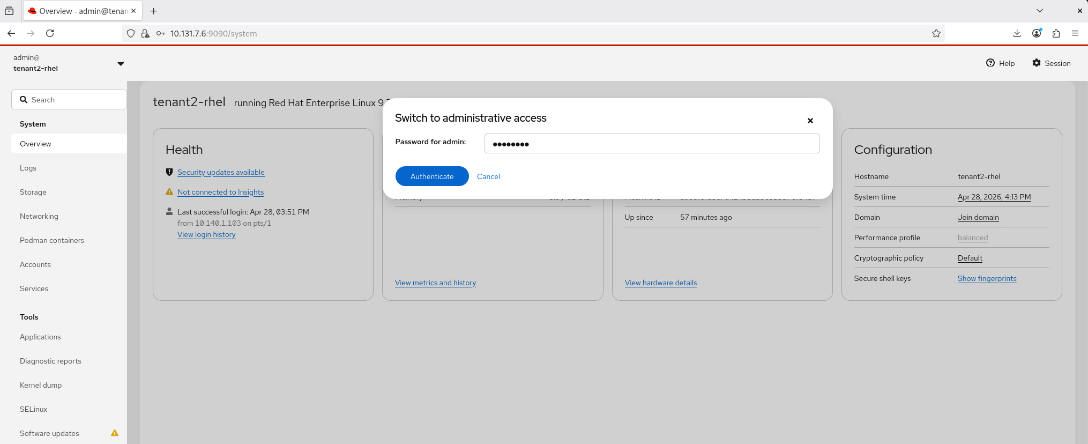
Step 9. Click System > Podman containers, you should be able to see the container podman-ui-test that we created in the previous step.
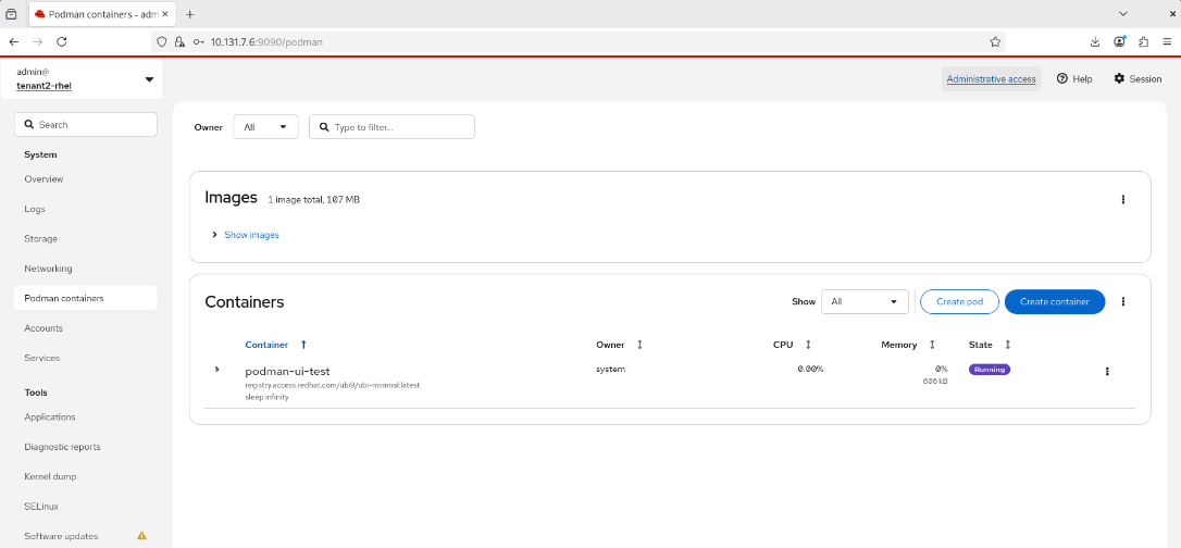
Step 10. Click the ellipses (…) and from the drop-down list, click Stop to stop it first.
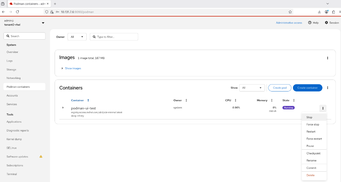
Step 11. After the container status changes to Exited, click the ellipses (…) and from the drop-down list, click Delete to delete the container.
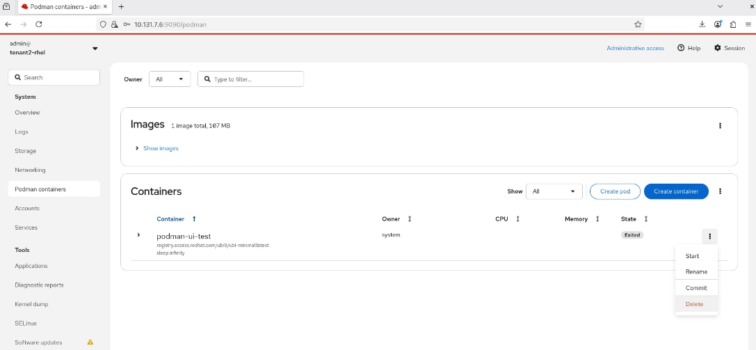
KVM
At a high level, the procedure outlined in this section verifies that hardware virtualization support is available and that the host meets the prerequisites for running virtual machines. It then enables the necessary libvirt services, confirms that the virtualization stack is functioning correctly, and installs the RHEL web console with the virtualization plug-in for browser-based VM management. Finally, the procedure validates the setup by creating, accessing, shutting down, and deleting a test virtual machine.
Procedure 1. Install KVM and Verify Hardware Virtualization Support
Step 1. Verify that the operating system detects hardware virtualization support from the CPU.
lscpu | egrep -i 'Virtualization|Hypervisor'
The output should include Virtualization: VT-x
If VT-x is not shown, hardware virtualization may not be enabled in the BIOS/UEFI or exposed to the operating system.
Step 2. Confirm that KVM kernel modules are loaded.
After confirming CPU virtualization support, verify that the required KVM kernel modules are loaded in RHEL.
lsmod | egrep '^kvm|kvm_intel'
The output should include entries for kvm_intel and kvm.
Step 3. Verify Intel VT-d / IOMMU is enabled inside RHEL.
Step 4. Install KVM validation tools.
sudo dnf install -y libvirt-client
Step 5. Run the KVM host validation tool to verify that all prerequisites for running virtual machines are met.
sudo virt-host-validate
The command virt-host-validate should show PASS for both hardware virtualization and IOMMU-related checks. Look for lines like:
● QEMU: Checking for device assignment IOMMU support : PASS
● QEMU: Checking if IOMMU is enabled by kernel : PASS
Step 6. If virt-host-validate shows WARN for IOMMU is enabled by kernel, follow the next steps to add the required kernel parameters.
$ sudo virt-host-validate
QEMU: Checking for hardware virtualization : PASS
QEMU: Checking if device '/dev/kvm' exists : PASS
QEMU: Checking if device '/dev/kvm' is accessible : PASS
QEMU: Checking if device '/dev/vhost-net' exists : PASS
QEMU: Checking if device '/dev/net/tun' exists : PASS
QEMU: Checking for cgroup 'cpu' controller support : PASS
QEMU: Checking for cgroup 'cpuacct' controller support : PASS
QEMU: Checking for cgroup 'cpuset' controller support : PASS
QEMU: Checking for cgroup 'memory' controller support : PASS
QEMU: Checking for cgroup 'devices' controller support : PASS
QEMU: Checking for cgroup 'blkio' controller support : PASS
QEMU: Checking for device assignment IOMMU support : PASS
QEMU: Checking if IOMMU is enabled by kernel : WARN (IOMMU appears to be disabled in kernel. Add intel_iommu=on to kernel cmdline arguments)
QEMU: Checking for secure guest support : WARN (Unknown if this platform has Secure Guest support)
Step 7. If VT-d/IOMMU is not enabled in the kernel, then check the current kernel command line. It should include intel_iommu=on.
$ cat /proc/cmdline
BOOT_IMAGE=(hd0,gpt2)/vmlinuz-5.14.0-611.47.1.el9_7.x86_64 root=/dev/mapper/rhel-root ro resume=/dev/mapper/rhel-swap rd.lvm.lv=rhel/root rd.lvm.lv=rhel/swap rhgb quiet crashkernel=1G-2G:192M,2G-64G:256M,64G-:512M
Step 8. If intel_iommu=on is missing, add the required IOMMU kernel parameters and reboot:
● The intel_iommu=on parameter enables the Intel VT-d IOMMU in the Linux kernel.
● The iommu=pt parameter enables passthrough mode, which improves performance by allowing DMA-capable devices to bypass the IOMMU remapping overhead for devices that do not require isolation.
sudo grubby --args="intel_iommu=on iommu=pt" --update-kernel DEFAULT
sudo reboot
Step 9. After the reboot, run the following two commands to confirm that the IOMMU kernel parameters were applied successfully and that the virtualization host validation now passes.
● The command /proc/cmdline now should contain intel_iommu=on.
● The command virt-host-validate no longer warns that IOMMU is disabled.
cat /proc/cmdline
sudo virt-host-validate
Here are the sample outputs:
$ cat /proc/cmdline
[sudo] password for admin:
BOOT_IMAGE=(hd0,gpt2)/vmlinuz-5.14.0-611.47.1.el9_7.x86_64 root=/dev/mapper/rhel-root ro resume=/dev/mapper/rhel-swap rd.lvm.lv=rhel/root rd.lvm.lv=rhel/swap rhgb quiet crashkernel=1G-2G:192M,2G-64G:256M,64G-:512M intel_iommu=on iommu=pt
$ sudo virt-host-validate
QEMU: Checking for hardware virtualization : PASS
QEMU: Checking if device '/dev/kvm' exists : PASS
QEMU: Checking if device '/dev/kvm' is accessible : PASS
QEMU: Checking if device '/dev/vhost-net' exists : PASS
QEMU: Checking if device '/dev/net/tun' exists : PASS
QEMU: Checking for cgroup 'cpu' controller support : PASS
QEMU: Checking for cgroup 'cpuacct' controller support : PASS
QEMU: Checking for cgroup 'cpuset' controller support : PASS
QEMU: Checking for cgroup 'memory' controller support : PASS
QEMU: Checking for cgroup 'devices' controller support : PASS
QEMU: Checking for cgroup 'blkio' controller support : PASS
QEMU: Checking for device assignment IOMMU support : PASS
QEMU: Checking if IOMMU is enabled by kernel : PASS
QEMU: Checking for secure guest support : WARN (Unknown if this platform has Secure Guest support)
Step 10. Install the KVM hypervisor and supporting tools using the following command.
sudo dnf install -y qemu-kvm libvirt virt-install virt-viewer
This installs four components:
● qemu-kvm provides the core machine emulator and hypervisor
● libvirt provides the virtualization management API and daemon
● virt-install is a command-line tool for provisioning new virtual machines
● virt-viewer provides a graphical console for connecting to running VMs.
Here are sample outputs:
$ sudo dnf install -y qemu-kvm libvirt virt-install virt-viewer
[sudo] password for admin:
Updating Subscription Management repositories.
…
Complete!
Procedure 2. Start the virtualization services
Step 1. Enable and start the libvirt modular daemon sockets for all required virtualization subsystems.
The libvirt modular architecture on RHEL 9 uses individual daemons for each subsystem (QEMU, networking, storage, and so on) instead of a single monolithic libvirtd process. This command enables the required modular libvirt sockets for the main virtualization subsystems in a single loop.
sudo bash -c 'for drv in qemu network nodedev nwfilter secret storage interface; do systemctl enable --now virt${drv}d{,-ro,-admin}.socket; done'
Step 2. Verify that the two most critical libvirt sockets are in Active: active (listening) state.
● The virtqemud socket is required for all VM lifecycle operations (create, start, stop, delete).
● The virtnetworkd socket is required for virtual network management, including the default NAT network that new VMs use
sudo systemctl status virtqemud.socket
sudo systemctl status virtnetworkd.socket
Here are the sample outputs:
$ sudo systemctl status virtqemud.socket
● virtqemud.socket - libvirt QEMU daemon socket
Loaded: loaded (/usr/lib/systemd/system/virtqemud.socket; enabled; preset: enabled)
Active: active (listening) since Thu 2026-04-09 15:24:46 EDT; 19min ago
Until: Thu 2026-04-09 15:24:46 EDT; 19min ago
Triggers: ● virtqemud.service
Listen: /run/libvirt/virtqemud-sock (Stream)
CGroup: /system.slice/virtqemud.socket
$ sudo systemctl status virtnetworkd.socket
● virtnetworkd.socket - libvirt network daemon socket
Loaded: loaded (/usr/lib/systemd/system/virtnetworkd.socket; enabled; preset: enabled)
Active: active (listening) since Thu 2026-04-09 15:24:46 EDT; 19min ago
Until: Thu 2026-04-09 15:24:46 EDT; 19min ago
Triggers: ● virtnetworkd.service
Listen: /run/libvirt/virtnetworkd-sock (Stream)
CGroup: /system.slice/virtnetworkd.socket
Step 3. Confirm that libvirt recognizes KVM acceleration.
Step 4. Verify that the host capabilities reported by libvirt include KVM acceleration.
sudo virsh capabilities | grep -i kvm
Note: The output should include kvm.
This confirms that libvirt detects KVM support on the host and that the virtualization stack is ready to run KVM-based virtual machines.
Step 5. Use the virsh command-line tool to connect to the local libvirt daemon and list all known virtual machines. On a fresh installation, the output will show an empty table with no VMs listed, which is the expected result.
sudo virsh list --all
The sample outputs are shown below:
$ virsh list --all
Id Name State
--------------------
$
Procedure 3. Install Cockpit and the virtualization plug-in
Step 1. Install Cockpit and virtualization plug-in, which adds the ability to manage VMs.
sudo dnf install -y cockpit
sudo dnf install -y cockpit-machines
sudo systemctl enable --now cockpit.socket
Step 2. Open firewall access for cockpit.
sudo firewall-cmd --add-service=cockpit --permanent
sudo firewall-cmd --reload
sudo firewall-cmd --list-services
The command sudo firewall-cmd --list-services should confirm cockpit appears in allowed services
$ sudo firewall-cmd --add-service=cockpit --permanent
Warning: ALREADY_ENABLED: cockpit
success
$ sudo firewall-cmd --reload
success
$ sudo firewall-cmd --list-services
cockpit dhcpv6-client ssh
Step 3. Enable and start the Cockpit socket.
sudo systemctl enable --now cockpit.socket
Step 4. Verify the Cockpit socket is active and listening.
sudo systemctl status cockpit.socket --no-pager
As you can see in the sample outputs below, the socket status shows Active: active (listening) and is listening on port 9090.
[admin@tenant2-rhel ~]$ sudo systemctl status cockpit.socket --no-pager
● cockpit.socket - Cockpit Web Service Socket
Loaded: loaded (/usr/lib/systemd/system/cockpit.socket; enabled; preset: disabled)
Active: active (listening) since Tue 2026-04-28 16:33:44 EDT; 21min ago
Until: Tue 2026-04-28 16:33:44 EDT; 21min ago
Triggers: ● cockpit.service
Docs: man:cockpit-ws(8)
Listen: [::]:9090 (Stream)
Tasks: 0 (limit: 407155)
Memory: 1.3M (peak: 3.2M)
CPU: 18ms
CGroup: /system.slice/cockpit.socket
Apr 28 16:33:44 tenant2-rhel systemd[1]: Starting Cockpit Web Service Socket...
Apr 28 16:33:44 tenant2-rhel systemd[1]: Listening on Cockpit Web Service Socket.
Procedure 4. VM Testing and Validation
Step 1. Save RHEL 9.6 ISO image to a local directory called /var/lib/libvirt/images/.
$ sudo ls /var/lib/libvirt/images/
RHEL-9.6.0-20250408.20-x86_64-dvd1.iso
Note: The ISO filename shown (RHEL-9.6.0-20250408.20-x86_64-dvd1.iso) is specific to this validated build. Your downloaded ISO filename may differ.
Step 2. Open a web browser and go to https://YOUR_RHEL_HOSTNAME_OR_IP:9090. Log in as a non-root user, for example, admin.
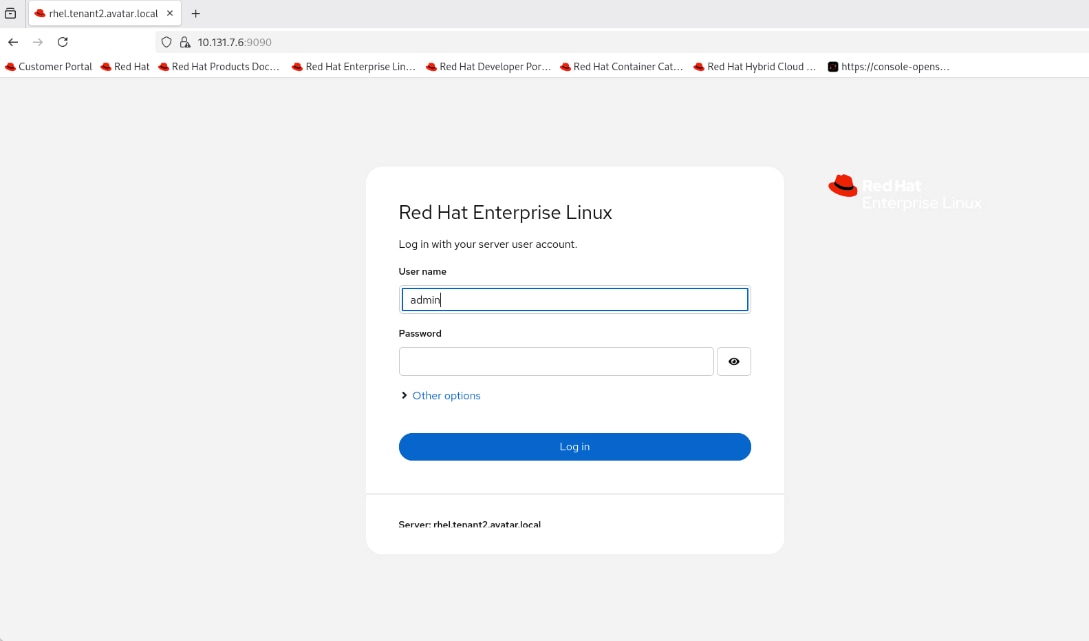
Step 3. After logging in, click System > Virtual machines in the left panel. There should be no VM available since it is a fresh installation. Click Limited access at the upper-right corner.
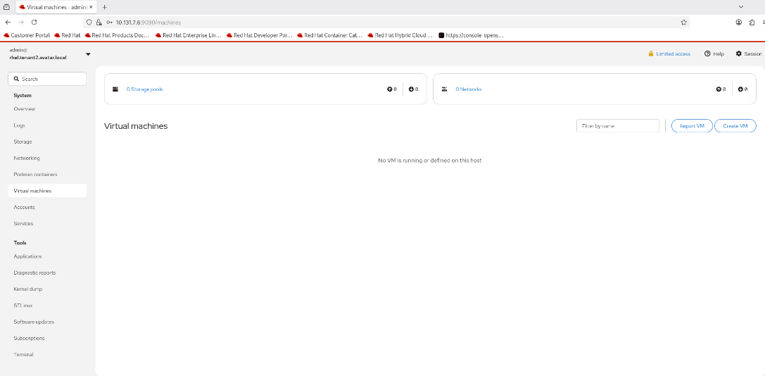
Step 4. In the confirmation window, provide the password and click Authenticate. Now the session should have root access.
Step 5. Click Create VM at the upper-right corner.
Step 6. In the Create new virtual machine window, use a small but workable configuration for a VM running RHEL 9.6.
● Name: test-vm
● Connection: choose System
● Installation type/source: Use Local install image (ISO image or distro install tree). The ISO image is accessible at /var/lib/libvirt/images/RHEL-9.6.0-20250408.20-x86_64-dvd1.iso
● Operating system: choose Red Hat Enterprise Linux 9.6 (Plow)
● Storage: Choose Create new qcow2 volume
● Storage limit: Set to 30 GiB
● Memory: Set to 2 GiB
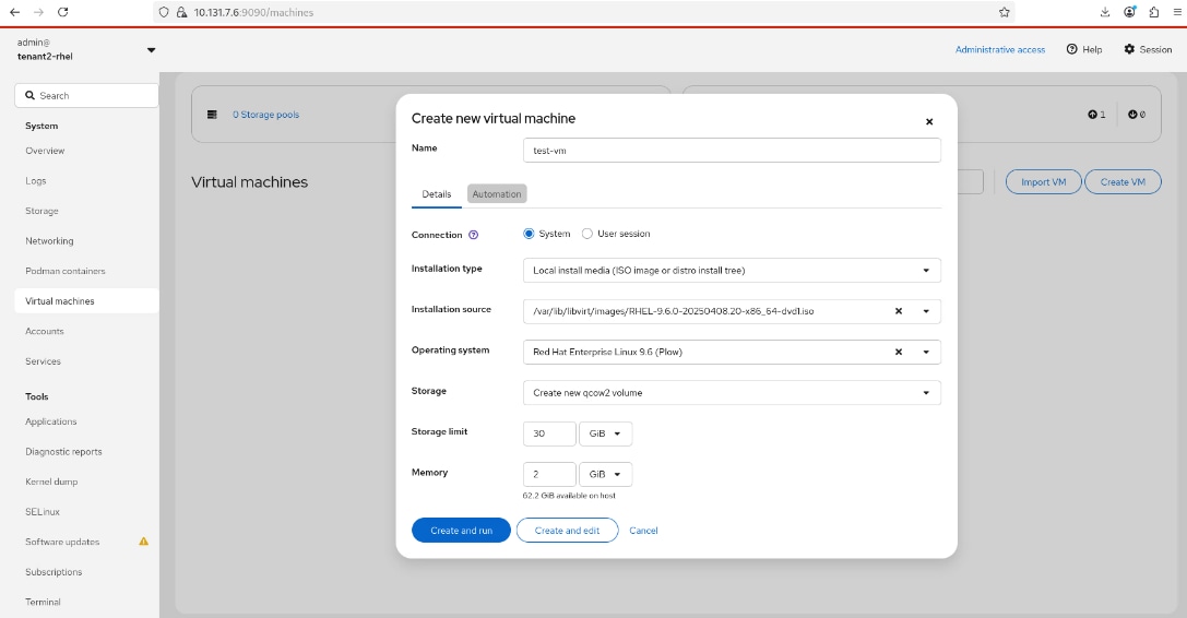
Step 7. Click Create and run.
Step 8. Back to the Virtual machines page, the VM test-vm should be in Running state. Click test-vm to expand its details.
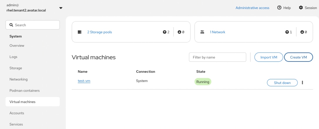
Step 9. In Console section, click Graphical tab. You should see the interactive OS installation UI for RHEL 9.6
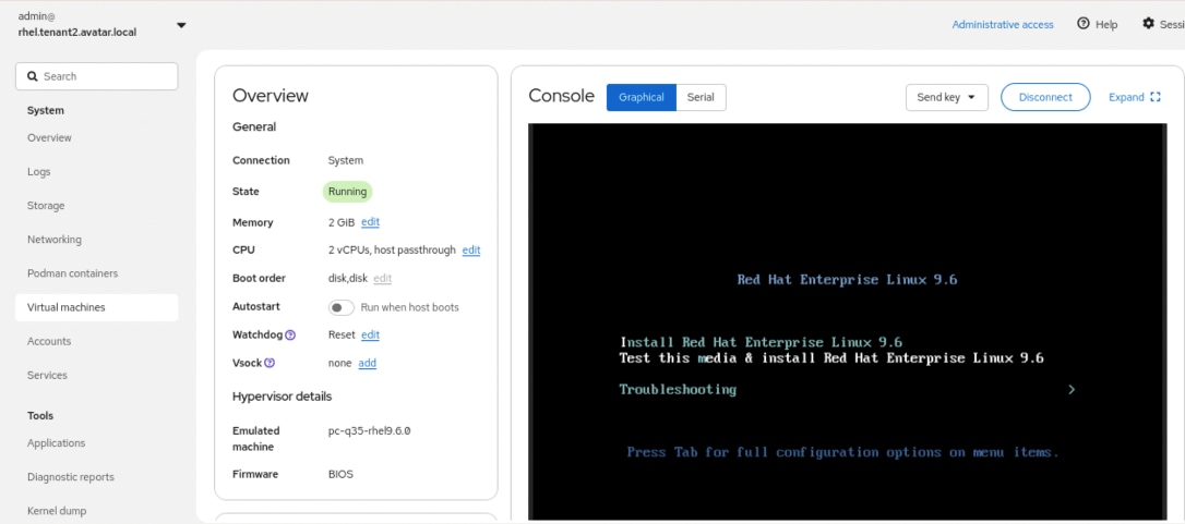
Step 10. After the installation completes, the VM test-vm will reboot.
Step 11. On the login page for the VM test-vm, log in as the user you created and verify that the VM is working properly.
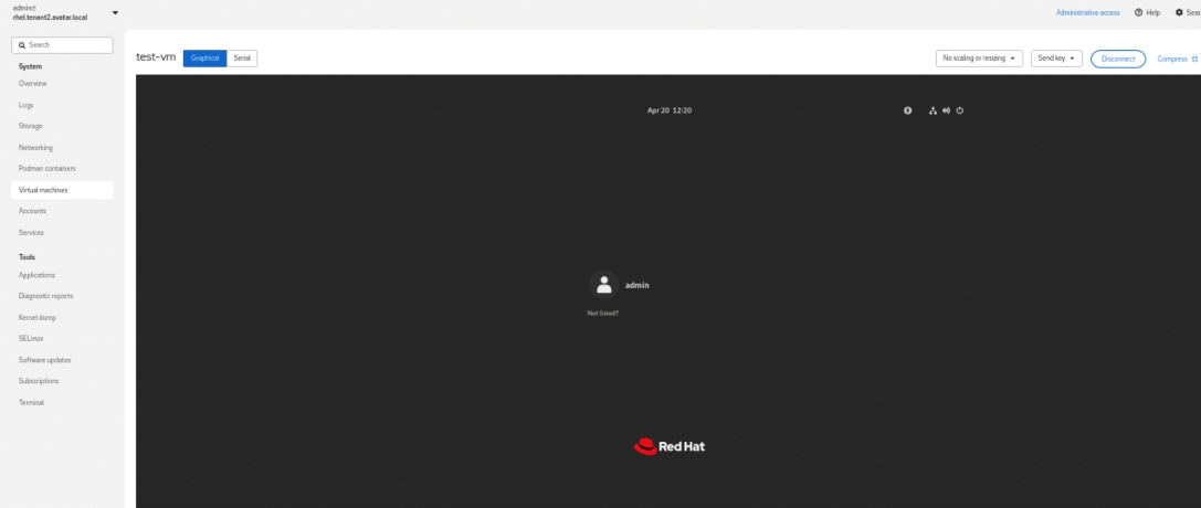
Step 12. Click Virtual machines in the left panel, click Shut down button towards the end of the line for test-vm.
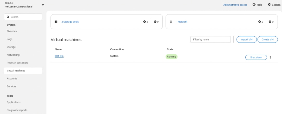
Step 13. In the confirmation window, click Shut down button. The State of VM should change to Shut off.
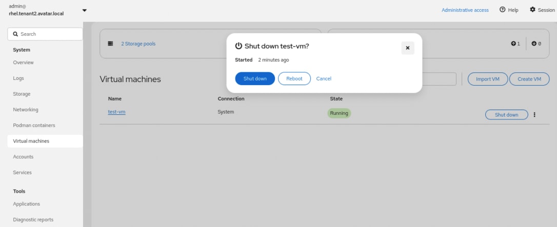
Step 14. Click the ellipses (…) at the end of the row. From the drop-down list, click Delete.
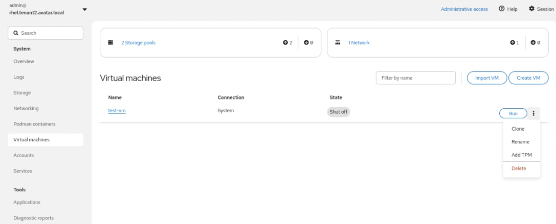
Step 15. In the confirmation window, make sure the vda checkbox is selected, then click Delete.
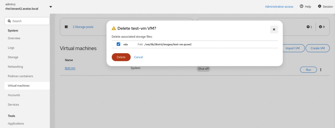
Step 16. The VM test-vm should be successfully deleted and the list in Virtual machines page is empty.
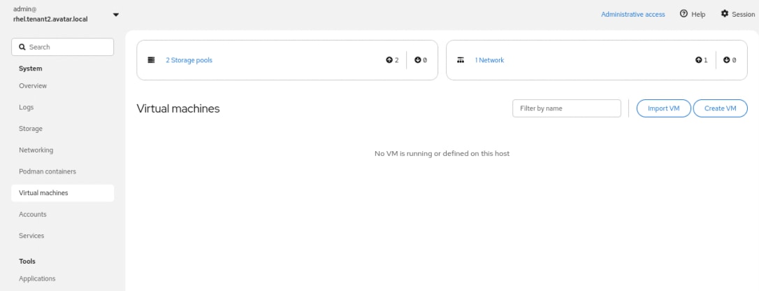
Step 17. (Optional) You can remove the ISO image in /var/lib/libvirt/images directory to free up the disk space.
NVIDIA GPU Enablement for Podman on RHEL 9
At a high level, the procedure in this section prepares the RHEL 9 host for NVIDIA GPU enablement with Podman by disabling the Nouveau driver, updating the kernel boot parameters, and rebuilding the initramfs to ensure the required changes persist across reboots. It then installs the NVIDIA driver, NVIDIA Container Toolkit, and required supporting packages, verifies that the NVIDIA L4 GPU is correctly recognized by the host operating system, and configures Podman for GPU-enabled container execution. Finally, the procedure validates the end-to-end configuration by running a test container and confirming successful GPU access from within the container.
Note: Secure Boot should be disabled before proceeding with this procedure unless you are using a supported signed-module workflow for the NVIDIA driver. Verify the current state by running mokutil --sb-state command, and the expected result should contain SecureBoot disabled.
Note: NVIDIA recommends disabling Nouveau on systems configured to use it before attempting to install the NVIDIA driver. This applies to RHEL 9.x systems with NVIDIA L4 GPUs.
Procedure 1. Enable NVIDIA GPU for Podman on RHEL 9
Step 1. Disable Nouveau using modprobe blacklist file.
sudo tee /etc/modprobe.d/blacklist-nouveau.conf >/dev/null <<'EOF'
blacklist nouveau
options nouveau modeset=0
EOF
Step 2. Add persistent kernel boot args to disable Nouveau.
sudo grubby --update-kernel=ALL --args="rd.driver.blacklist=nouveau modprobe.blacklist=nouveau"
Step 3. Rebuild initramfs.
Nouveau may already be present in the initramfs, so just dropping a blacklist file is not always enough.
echo 'omit_drivers+=" nouveau "' | sudo tee /etc/dracut.conf.d/omit-nouveau.conf
sudo dracut --force /boot/initramfs-$(uname -r).img $(uname -r)
Step 4. Reboot into multi-user / text mode for install.
NVIDIA recommends booting to a VGA/text console while doing the install. That avoids the GUI stack grabbing devices during the transition.
For a one-time safe install window:
sudo systemctl set-default multi-user.target
sudo reboot
Step 5. On Intersight Tunneled vKVM, verify that RHEL boots into text mode, then log in with a user account that has sudo privileges.
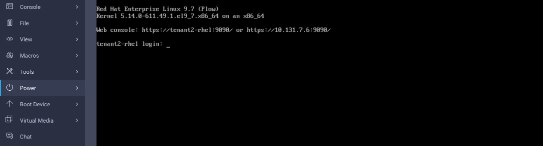
Step 6. Confirm Nouveau is disabled.
lsmod | grep nouveau
lspci -nnk | grep -A3 -i nvidia
Expected result:
● The lsmod command returns no loaded nouveau module.
● The lspci output does not show Kernel driver in use: nouveau for the NVIDIA GPU.
Step 7. Enable Repositories and Update Kernel.
Ensure the system is running the latest kernel and has access to the EPEL repository.
# Install EPEL
sudo dnf install -y https://dl.fedoraproject.org/pub/epel/epel-release-latest-9.noarch.rpm
# Update the system and reboot to ensure we are on the latest kernel
sudo dnf update -y
sudo reboot
Note: dnf update can move a RHEL host to the latest available minor release within the same major RHEL 9 version unless the system is pinned/release-locked or using constrained repos.
After reboot, confirm the system is running the expected kernel version by using uname -r.
Step 8. Install Build Dependencies.
Install the headers and compiler tools required to build the NVIDIA kernel module.
sudo dnf -y install curl wget jq git pciutils lshw podman gcc make dkms kernel-devel-$(uname -r) kernel-headers-$(uname -r)
Step 9. Install NVIDIA Drivers.
Add the NVIDIA repository and install the driver packages.
# Add NVIDIA Repository
sudo curl -s -L https://developer.download.nvidia.com/compute/cuda/repos/rhel9/$(uname -i)/cuda-rhel9.repo -o /etc/yum.repos.d/cuda-rhel9.repo
# Clean cache and install drivers
sudo dnf clean all
sudo dnf -y install nvidia-driver nvidia-driver-NVML nvidia-driver-cuda
Step 10. Verify that DKMS has successfully compiled and installed the NVIDIA kernel module for the currently running kernel by running dkms status. The output should show the NVIDIA driver installed for the same kernel version returned by uname -r.
$ uname -r
5.14.0-611.49.1.el9_7.x86_64
$ dkms status
nvidia/595.58.03, 5.14.0-611.49.1.el9_7.x86_64, x86_64: installed
Note: If the driver was built for a different kernel version, ensure the system has rebooted into the latest kernel and reinstall or rebuild the driver as needed.
Step 11. Reboot and verify ownership of NVIDIA L4 GPU.
sudo reboot
lspci -nnk | grep -A3 -i nvidia
lsmod | egrep 'nvidia|nouveau'
Expected result:
● The lsmod command returns no loaded nouveau module.
● The lspci output shows Kernel driver in use: nvidia
The Kernel modules line may still list nouveau; this is expected. The important check is that Kernel driver in use shows nvidia and lsmod does not show nouveau.
The sample outputs are shown below:
$ lsmod | grep nouveau
$ lspci -nnk | grep -A3 -i nvidia
60:00.0 3D controller [0302]: NVIDIA Corporation AD104GL [L4] [10de:27b8] (rev a1)
Subsystem: NVIDIA Corporation Device [10de:16ca]
Kernel driver in use: nvidia
Kernel modules: nouveau, nvidia_drm, nvidia
ad:00.0 System peripheral [0880]: Intel Corporation Ice Lake Memory Map/VT-d [8086:09a2]
Subsystem: Intel Corporation Ice Lake Memory Map/VT-d [8086:09a2]
ad:00.1 System peripheral [0880]: Intel Corporation Ice Lake Mesh 2 PCIe [8086:09a4]
Step 12. Verify NVIDIA GPU is accessible.
Run nvidia-smi command to confirm the host can communicate with the GPU. In the output, you should see a table showing the GPU (for example, NVIDIA L4), Driver Version (for example, 595.58.03), and Memory Usage.
$ nvidia-smi
Tue Apr 21 12:33:28 2026
+-----------------------------------------------------------------------------------------+
| NVIDIA-SMI 595.58.03 Driver Version: 595.58.03 CUDA Version: 13.2 |
+-----------------------------------------+------------------------+----------------------+
| GPU Name Persistence-M | Bus-Id Disp.A | Volatile Uncorr. ECC |
| Fan Temp Perf Pwr:Usage/Cap | Memory-Usage | GPU-Util Compute M. |
| | | MIG M. |
|=========================================+========================+======================|
| 0 NVIDIA L4 Off | 00000000:60:00.0 Off | 0 |
| N/A 34C P8 12W / 72W | 0MiB / 23034MiB | 0% Default |
| | | N/A |
+-----------------------------------------+------------------------+----------------------+
+-----------------------------------------------------------------------------------------+
| Processes: |
| GPU GI CI PID Type Process name GPU Memory |
| ID ID Usage |
|=========================================================================================|
| No running processes found |
+-----------------------------------------------------------------------------------------+
Step 13. Install NVIDIA Container Toolkit.
This allows Podman to interface with the NVIDIA driver libraries.
# Add Toolkit Repository
sudo curl -s -L https://nvidia.github.io/libnvidia-container/stable/rpm/nvidia-container-toolkit.repo -o /etc/yum.repos.d/nvidia-container-toolkit.repo
# Install Toolkit
sudo dnf -y install nvidia-container-toolkit
Step 14. Configure Podman GPU Integration (CDI). Generate the Container Device Interface (CDI) specification.
# Generate CDI symlinks and configuration
sudo nvidia-ctk cdi generate --output=/etc/cdi/nvidia.yaml
Step 15. To verify, run the following command and the result should include nvidia.com/gpu=all.
sudo nvidia-ctk cdi list
Sample outputs are shown below:
$ sudo nvidia-ctk cdi list
INFO[0000] Found 3 CDI devices
nvidia.com/gpu=0
nvidia.com/gpu=GPU-b8f35dea-df0d-6c34-0f15-a229c8114d87
nvidia.com/gpu=all
Step 16. Final Verification. Run a UBI-based CUDA container to verify end-to-end GPU passthrough.
sudo podman run --rm -it --security-opt=label=disable --device nvidia.com/gpu=all nvcr.io/nvidia/cuda:12.4.1-base-ubi9 nvidia-smi
Here is the sample output:
$ sudo podman run --rm -it --security-opt=label=disable --device nvidia.com/gpu=all nvcr.io/nvidia/cuda:12.4.1-base-ubi9 nvidia-smi
…
Tue Apr 21 16:44:29 2026
+-----------------------------------------------------------------------------------------+
| NVIDIA-SMI 595.58.03 Driver Version: 595.58.03 CUDA Version: 13.2 |
+-----------------------------------------+------------------------+----------------------+
| GPU Name Persistence-M | Bus-Id Disp.A | Volatile Uncorr. ECC |
| Fan Temp Perf Pwr:Usage/Cap | Memory-Usage | GPU-Util Compute M. |
| | | MIG M. |
|=========================================+========================+======================|
| 0 NVIDIA L4 Off | 00000000:60:00.0 Off | 0 |
| N/A 39C P8 16W / 72W | 0MiB / 23034MiB | 0% Default |
| | | N/A |
+-----------------------------------------+------------------------+----------------------+
+-----------------------------------------------------------------------------------------+
| Processes: |
| GPU GI CI PID Type Process name GPU Memory |
| ID ID Usage |
|=========================================================================================|
| No running processes found |
+-----------------------------------------------------------------------------------------+
Step 17. Switch back to graphical interface.
If you want the system to boot into the graphical desktop environment after the NVIDIA driver has been installed and verified, set the default systemd target back to graphical.target and reboot.
sudo systemctl set-default graphical.target
sudo reboot
Expected result:
● The graphical login screen is visible on the local console or vKVM.
● NVIDIA GPU access remains functional, and the nvidia-smi command continues to work as expected.
Note: If the graphical login screen does not appear but SSH access still works, disable /etc/X11/xorg.conf.d/10-nvidia.conf and reboot.
Conclusion
This document details the end-to-end deployment of Red Hat Enterprise Linux (RHEL) 9.6 with Podman and KVM on the Cisco Unified Edge platform, from initial Cisco Intersight configuration through OS installation, post-boot networking, subscription activation, and workload validation. The validated design brings together the Cisco UCS XE9305 chassis, cloud-based management through Cisco Intersight, and Red Hat Enterprise Linux to deliver a consistent and repeatable edge deployment that supports containerized workloads via Podman and virtual machines via KVM/libvirt, all on a single RHEL host.
The validated procedures confirmed that Podman correctly pulls and runs container workloads using Red Hat's Universal Base Image, and that KVM with libvirt successfully provisions and manages virtual machines on the RHEL host. By following the steps and configurations documented in this guide, organizations can deploy this solution with confidence, knowing that the architecture has been tested and validated across both Cisco Meraki and Cisco Catalyst network environments. As edge requirements continue to evolve, the modular nature of this platform allows additional capabilities including GPU-accelerated workloads and expanded container orchestration to be introduced without disrupting existing deployments.
About the authors
Shixiong Shang, Technical Marketing Engineer, UCS Solutions, Cisco Systems, Inc.
Shixiong Shang has over 25 years of experience in routing, switching, and enterprise applications. He specializes in infrastructure automation, virtualization, OpenShift/Kubernetes, cloud computing and AI. Shixiong is passionate about open-source technologies and has deep expertise in operations and observability.
Jonathan Wong, Solutions Architect, Red Hat
Jonathan has over 20 years of experience in the industry specializing in OpenShift/Kubernetes, Virtualization, AI, and Cloud Computing.
Acknowledgements
For their support and contribution to the design, validation, and creation of this Cisco Validated Design, the authors would like to thank:
● Chris O’Brien, Director, UCS Solutions, Cisco Systems, Inc.
● Ulrich Kleidon, Principal Engineer, UCS Solutions, Cisco Systems, Inc.
Appendix
This appendix contains the following:
Red Hat: Managing systems using the RHEL 9 web console https://docs.redhat.com/en/documentation/red_hat_enterprise_linux/9/html-single/managing_systems_using_the_rhel_9_web_console/index?utm_source=chatgpt.com
Red Hat: Managing virtual machines in the web console https://docs.redhat.com/en/documentation/red_hat_enterprise_linux/9/html/configuring_and_managing_virtualization/managing-virtual-machines-in-the-web-console_configuring-and-managing-virtualization?utm_source=chatgpt.com
Red Hat: Configuring and managing virtualization https://docs.redhat.com/en/documentation/red_hat_enterprise_linux/9/html/configuring_and_managing_virtualization/index?utm_source=chatgpt.com
Red Hat: Enabling virtualization https://docs.redhat.com/en/documentation/red_hat_enterprise_linux/9/html/configuring_and_managing_virtualization/assembly_enabling-virtualization-in-rhel-9_configuring-and-managing-virtualization?utm_source=chatgpt.com
Red Hat: Building, running, and managing containers https://docs.redhat.com/en/documentation/red_hat_enterprise_linux/9/html-single/building_running_and_managing_containers/index?utm_source=chatgpt.com
NVIDIA: Red Hat Enterprise Linux — NVIDIA Driver Installation Guide https://docs.nvidia.com/datacenter/tesla/driver-installation-guide/red-hat-enterprise-linux.html?utm_source=chatgpt.com
NVIDIA: Support for Container Device Interface — NVIDIA Container Toolkit https://docs.nvidia.com/datacenter/cloud-native/container-toolkit/latest/cdi-support.html?utm_source=chatgpt.com
NVIDIA: L4 Tensor Core GPU for AI & Graphics https://www.nvidia.com/en-us/data-center/l4/?utm_source=chatgpt.com
CVD Program
ALL DESIGNS, SPECIFICATIONS, STATEMENTS, INFORMATION, AND RECOMMENDATIONS (COLLECTIVELY, "DESIGNS") IN THIS MANUAL ARE PRESENTED "AS IS," WITH ALL FAULTS. CISCO AND ITS SUPPLIERS DISCLAIM ALL WARRANTIES, INCLUDING, WITHOUT LIMITATION, THE WARRANTY OF MERCHANTABILITY, FITNESS FOR A PARTICULAR PURPOSE AND NONINFRINGEMENT OR ARISING FROM A COURSE OF DEALING, USAGE, OR TRADE PRACTICE. IN NO EVENT SHALL CISCO OR ITS SUPPLIERS BE LIABLE FOR ANY INDIRECT, SPECIAL, CONSEQUENTIAL, OR INCIDENTAL DAMAGES, INCLUDING, WITHOUT LIMITATION, LOST PROFITS OR LOSS OR DAMAGE TO DATA ARISING OUT OF THE USE OR INABILITY TO USE THE DESIGNS, EVEN IF CISCO OR ITS SUPPLIERS HAVE BEEN ADVISED OF THE POSSIBILITY OF SUCH DAMAGES.
THE DESIGNS ARE SUBJECT TO CHANGE WITHOUT NOTICE. USERS ARE SOLELY RESPONSIBLE FOR THEIR APPLICATION OF THE DESIGNS. THE DESIGNS DO NOT CONSTITUTE THE TECHNICAL OR OTHER PROFESSIONAL ADVICE OF CISCO, ITS SUPPLIERS OR PARTNERS. USERS SHOULD CONSULT THEIR OWN TECHNICAL ADVISORS BEFORE IMPLEMENTING THE DESIGNS. RESULTS MAY VARY DEPENDING ON FACTORS NOT TESTED BY CISCO.
CCDE, CCENT, Cisco Eos, Cisco Lumin, Cisco Nexus, Cisco StadiumVision, Cisco TelePresence, Cisco WebEx, the Cisco logo, DCE, and Welcome to the Human Network are trademarks; Changing the Way We Work, Live, Play, and Learn and Cisco Store are service marks; and Access Registrar, Aironet, AsyncOS, Bringing the Meeting To You, Catalyst, CCDA, CCDP, CCIE, CCIP, CCNA, CCNP, CCSP, CCVP, Cisco, the Cisco Certified Internetwork Expert logo, Cisco IOS, Cisco Press, Cisco Systems, Cisco Systems Capital, the Cisco Systems logo, Cisco Unified Computing System (Cisco UCS), Cisco UCS B-Series Blade Servers, Cisco UCS C-Series Rack Servers, Cisco UCS S-Series Storage Servers, Cisco UCS X-Series, Cisco UCS Manager, Cisco UCS Management Software, Cisco Unified Fabric, Cisco Application Centric Infrastructure, Cisco Nexus 9000 Series, Cisco Nexus 7000 Series. Cisco Prime Data Center Network Manager, Cisco NX-OS Software, Cisco MDS Series, Cisco Unity, Collaboration Without Limitation, EtherFast, EtherSwitch, Event Center, Fast Step, Follow Me Browsing, FormShare, GigaDrive, HomeLink, Internet Quotient, IOS, iPhone, iQuick Study, LightStream, Linksys, MediaTone, MeetingPlace, MeetingPlace Chime Sound, MGX, Networkers, Networking Academy, Network Registrar, PCNow, PIX, PowerPanels, ProConnect, ScriptShare, SenderBase, SMARTnet, Spectrum Expert, StackWise, The Fastest Way to Increase Your Internet Quotient, TransPath, WebEx, and the WebEx logo are registered trade-marks of Cisco Systems, Inc. and/or its affiliates in the United States and certain other countries. (LDW_P2)
All other trademarks mentioned in this document or website are the property of their respective owners. The use of the word partner does not imply a partnership relationship between Cisco and any other company. (0809R)