Cisco Unified Edge for Red Hat Edge Design Guide
Available Languages
Bias-Free Language
The documentation set for this product strives to use bias-free language. For the purposes of this documentation set, bias-free is defined as language that does not imply discrimination based on age, disability, gender, racial identity, ethnic identity, sexual orientation, socioeconomic status, and intersectionality. Exceptions may be present in the documentation due to language that is hardcoded in the user interfaces of the product software, language used based on RFP documentation, or language that is used by a referenced third-party product. Learn more about how Cisco is using Inclusive Language.
- US/Canada 800-553-2447
- Worldwide Support Phone Numbers
- All Tools
 Feedback
 Feedback
In partnership with:

About the Cisco Validated Design Program
The Cisco Validated Design (CVD) program consists of systems and solutions designed, tested, and documented to facilitate faster, more reliable, and more predictable customer deployments. For more information, go to: http://www.cisco.com/go/designzone
Executive Summary
We’re at a critical inflection point. The edge has emerged as the place where the physical and digital worlds meet, demanding real-time processing and analysis of data to deliver informed decisions, improved experiences, and increased productivity. However, legacy infrastructure wasn’t built for the AI era and can’t keep up with the scale, speed, and intelligence required by AI-driven operations. While much of the model training happens in the data center, the shift of test-time inference to the edge makes it the new frontier for enterprise AI.
Deploying AI at the edge remains complicated and demanding. Interoperability, security, cost, and rigid deployment models are all potential performance and productivity blockers. The increasing demand for AI and digitization at the edge necessitates a full system rethink, as evolving business needs and the sheer scale highly distributed edge environments and modern AI workloads create a beyond-human complexity nightmare. We need something more than just more boxes; we need a brand-new edge infrastructure and operations vision.
Cisco Unified Edge is an AI-ready system that redefines computing at the edge by converging compute networking, storage, and security. Designed from the edge up, for the next decade, the modular design is future-ready, energy-efficient, and easy-to-service, and can be tailored to support today’s workloads and use cases, while remaining adaptable to the rapidly evolving AI landscape. Seamless integration with third-party technologies and validated solutions for industry-specific needs ensure both compatibility and optimized performance.
Delivering breakthrough operational simplicity at scale, this software-defined system features centralized cloud management, zero-touch deployment, curated blueprints, and automated orchestration. These capabilities enable high scalability with minimal complexity. End-to-end observability with real-time analytics accelerates error detection and correction, helping minimize service outages. Security is designed-in, with integrated physical and digital safeguards to protect applications and data at the edge while multi-layered security capabilities protect infrastructure, applications, and AI models.
Benefits
The key benefits are:
● Future-ready performance: Adaptable to meet today and tomorrow's edge workload demands with ease, stopping the rip-and-replace cycle with a fully integrated, modular edge environment built for the next decade. Deploy applications and infrastructure faster and profit sooner with proven solutions that are tested and certified for vertical-specific workloads and use cases, ensuring compatibility and performance.
● Full-scale simplicity: Onboard quickly and with ease without the need for highly skilled IT expertise or on-site visits. Whether deploying ten systems or ten thousand, zero-touch provisioning, curated blueprints and automation ensure consistent, effortless rollout. A consistent operating model from core to edge makes it easy to scale, upgrade, and support your infrastructure.
● Designed-in security: Prevent tampering at the edge with robust physical and digital protection. Proven policy-based templates eliminate configuration drift across sites. Embedded, zero-trust security capabilities ensure unmatched protection for your edge infrastructure, data, and AI models.
Red Hat, the leading provider of enterprise open-source solutions, offers a comprehensive and integrated portfolio of technologies designed to modernize enterprise IT operations, accelerate innovation, and reduce complexity across hybrid cloud, datacenter, and edge environments. This technical design guide explores how Red Hat's enterprise platform can be effectively deployed on Cisco Unified Edge System (Cisco UCS XE9305) to deliver scalable, secure, and mission-critical solutions.
Red Hat's enterprise-grade architecture aligns seamlessly with Cisco Unified Edge infrastructure model, enabling:
● Rapid provisioning and scaling of containerized and virtualized workloads
● Unified management and automation across compute, storage, and networking
● Optimized performance for cloud-native applications, traditional workloads, and AI/ML inference
● Enterprise support and certified interoperability for production environments
Together, Red Hat and Cisco Unified Edge empower enterprises to build resilient, future-ready platforms that support digital transformation, edge computing, and AI innovation.
The design of this solution is driven by its ability to evolve and incorporate both technology and product innovations in the areas of management, computing, storage, and networking to be used at the edge. To help organizations with their digital transformation and application modernization practices, Cisco and Red Hat have partnered to produce this Cisco Validated Design (CVD) for the joint Unified Edge and Red Hat edge solutions minimizing risks by validating the integrated architecture to ensure compatibility between various components. The solution also addresses pain points by providing documented design guidance, deployment guidance, and support that can be used in various stages (planning, designing, and implementation) of a business project targeting Edge deployments. The solution is part of Cisco’s Blueprint and Fleet management enhancement of Intersight and will be delivered as Infrastructure as Code (IaC) to further eliminate error-prone manual tasks, allowing quicker and more consistent solution deployments.
Solution Overview
This chapter contains the following:
● Audience
The deployment options use pre-designed, integrated, and validated architectures for the edge that combines Cisco Unified Edge - servers, network, security - and Red Hat products into a single, flexible architecture. The solutions are designed to meet a broad range of deployment options, while maintaining cost-effectiveness and flexibility to support a wide variety of workloads.
The range of deployment options goes from single node Linux host to run a small number of virtual machines or containers up to multi-node Kubernetes cluster with an integrated software defined storage option to provide full high-availability and scalability for a larger number of virtual machines, container-based applications, AI workloads and mission critical control units.
The following design and deployment aspects of this edge solution are explained in this document:
● Cisco Unified Edge
● Red Hat Enterprise Linux
● Podman and KVM (Kernel-based Virtual Machine)
● Single node OpenShift cluster and OpenShift Compact cluster
● Deployment options for virtual machines and container-based workloads
● Integration into edge networks
The intended audience of this document includes but is not limited to IT architects, sales engineers, field consultants, professional services, IT managers, partner engineering, and those who want to take advantage of an infrastructure built to deliver efficiency and enable innovation.
This document provides design guidance around incorporating the Cisco Intersight—managed Cisco Unified Edge platform to run Red Hat edge solutions. The document introduces various design elements and covers various considerations and best practices for a successful deployment.
The components are integrated and validated, and where possible, Intersight Blueprints will explain the installation and configuration of the entire stack so that you can deploy your solution quickly and economically, while eliminating many of the risks associated with researching, designing, building, and deploying similar solutions from the ground up.
The Cisco Unified Edge with Red Hat edge solution offers the following key benefits:
● Standardized architecture for quick, repeatable, error-free deployments of workload domains
● Automated life cycle management to keep all the system components up to date
● Simplified cloud-based management of various components
● Hybrid-cloud-ready, policy-driven modular design
● Highly available, flexible, and scalable architecture
● Cooperative support model and Cisco Solution Support
● Easy to deploy, consume, and manage design that aligns with Cisco and Red Hat best practices and compatibility requirements
● Support for component monitoring, solution automation and orchestration, and workload optimization
● Validated integration into Meraki and Catalyst network domains.
Like all other Cisco Validated solution designs, Unified Edge with Red Hat is configurable according to demand and usage. You can purchase the exact infrastructure needed for your current application requirements. You can scale-up by adding more resources to the solution or scale-out by adding more Unified Edge instances.
Technology Overview
This chapter contains the following:
● Cisco Unified Edge Management
● Podman
● KVM
Cisco Unified Edge with Red Hat is built using compute, network, and storage components integrate in the Unified Edge platform. The solution consists of the following core elements:
● Cisco Unified Edge System (Cisco UCS XE9305)
● Red Hat Enterprise Linux
● Podman and KVM
● Red Hat OpenShift
One of the key benefits of Cisco Unified Edge is its ability to maintain consistency during scale where required. Each of the components offers platform and resource options to scale the infrastructure up or down while supporting the same features and functionality that are required under the configuration and connectivity best practices. The key features and highlights of the components are explained in the following sections.
Cisco Unified Edge is part of the Cisco Unified Computing System (Cisco UCS) family designed from ground up to address deployments where traditional data center servers are not a perfect fit. With its new physical design and the new components, the Cisco Unified Edge uses, like other Cisco UCS platforms, Cisco Intersight as the management tool.
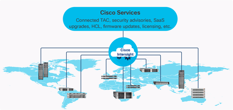
The Cisco Intersight platform is a Software-as-a-Service (SaaS) infrastructure lifecycle management platform that delivers simplified configuration, deployment, maintenance, and support. The Cisco Intersight platform is designed to be modular, so you can adopt services based on your individual requirements. The platform significantly simplifies IT operations by bridging applications with infrastructure, providing visibility and management from bare-metal servers and hypervisors to serverless applications, thereby reducing costs and mitigating risk. This unified SaaS platform uses an Open API design that natively integrates with third-party platforms and tools.
The capabilities of Cisco Intersight were extended with a Fleet Management option to automate and accelerate deployment of Cisco UCS and Unified Edge systems at remote locations at scale. With the new Fleet Management, it is possible to define location profiles and Blueprints to allow zero-touch provisioning of the hardware and operating systems as soon as the new hardware is claimed in Intersight.
While Cisco UCS XE9305 is a programmable infrastructure, the Cisco Intersight API is how management tools program it. This enables the tools to help guarantee consistent, error-free, policy-based alignment of server personalities with workloads. Through automation, transforming the server and networking components of your infrastructure into a complete solution is fast and error-free because programmability eliminates the error-prone manual configuration of servers and integration into solutions. Server, network, and storage administrators are now free to focus on strategic initiatives rather than spending their time performing tedious tasks.
The main benefits of Cisco Intersight infrastructure services are as follows:
● Simplify daily operations by automating many daily manual tasks
● Combine the convenience of a SaaS platform with the capability to connect from anywhere and manage infrastructure through a browser or mobile app
● Stay ahead of problems and accelerate trouble resolution through advanced support capabilities
● Gain global visibility of infrastructure health and status along with advanced management and support capabilities
Licensing Requirements
The Cisco Intersight platform uses a subscription-based license with multiple tiers. You can purchase a subscription duration of one, three, or five years and choose the required Cisco UCS server volume tier for the selected subscription duration. Each Cisco endpoint automatically includes a Cisco Intersight Base license at no additional cost when you access the Cisco Intersight portal and claim a device. You can purchase any of the following higher-tier Cisco Intersight licenses using the Cisco ordering tool:
● Cisco Intersight Infrastructure Services Essentials: The Essentials license tier offers server management with global health monitoring, inventory, proactive support through Cisco TAC integration, multi-factor authentication, along with SDK and API access.
● Cisco Intersight Infrastructure Services Advantage: The Advantage license tier offers advanced server management with extended visibility, ecosystem integration, and automation of Cisco and third-party hardware and software, along with multi-domain solutions.
Servers in the Cisco Intersight managed mode require at least the Essentials license. For detailed information about the features provided in the various licensing tiers, see https://intersight.com/help/getting_started#licensing_requirements.
DevOps and Tool Support
The Cisco Intersight API is of great benefit to developers and administrators who want to treat physical infrastructure the way they treat other application services, using processes that automatically provision or change IT resources. Similarly, your IT staff needs to provision, configure, and monitor physical and virtual resources; automate routine activities; and rapidly isolate and resolve problems. The Cisco Intersight API integrates with DevOps management tools and processes and enables you to easily adopt DevOps methodologies.
The Cisco Unified Edge Modular System is designed to take the current generation of the Cisco UCS platform to the next level with its future-ready design and cloud-based management. Decoupling and moving the platform management to the cloud allows Cisco UCS to respond to customer feature and scalability requirements in a much faster and more efficient manner. Cisco Unified Edge state of the art hardware simplifies the edge design by providing flexible server options.
Cisco UCS XE9305 Chassis
The Cisco Unified Edge chassis is engineered to be adaptable and flexible. As seen in Figure 3, the Cisco Unified Edge XE9305 chassis has a power-distribution backplane. This innovative design provides fewer obstructions for better airflow.
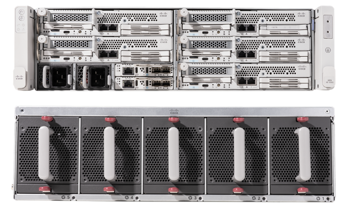
The Cisco UCS XE9305 3-Rack-Unit (3RU) chassis has five flexible slots. These slots can house a combination of compute nodes, and network nodes (future). At the bottom of the chassis are two edge Chassis Management Controller (ECMC) that connect the chassis to upstream network. On the left of the ECMCs there are two Power Supply Units (PSUs) provide power to the chassis with N+N redundancy. At the back of the chassis, five efficient, 80mm, dual counter-rotating fans deliver industry-leading airflow and power efficiency, and optimized thermal algorithms enable different cooling modes to best support the customer’s environment.
Cisco Unified Edge – Edge Chassis Management Controller
The Cisco Edge Chassis Management Controller (ECMC) provide a single point for connectivity and management for the entire Cisco Unified Edge system.
The Cisco Unified Edge ECMC provides the management and communication backbone for the Cisco UCS XE130c M8 compute nodes in the Cisco UCS XE9305 Series Chassis. All nodes attached to the Cisco Unified Edge ECMC become part of a single, highly available management domain.
Cisco Unified Edge ECMC utilized in the current design includes one Ethernet port for management, two Ethernet ports for data traffic and one Ethernet port to each slot in the chassis.
For more information about the Cisco Unified Edge ECMC Edge Chassis Management Controller see: https://www.cisco.com/c/en/us/products/collateral/servers-unified-computing/ucs6536-fabric-interconnect-ds.html.
Cisco UCS XE130c M8 Compute Node
The Cisco UCS XE9305 Chassis is designed to host up to five Cisco UCS XE130c Compute Nodes. The hardware details of the Cisco UCS XE130c M8 Compute Nodes are shown in Figure 4:
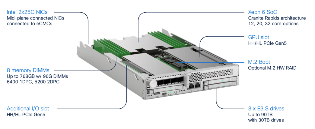
The Cisco UCS XE130c M8 features:
● CPU: One 6th Gen Intel Xeon SoC Processor with 12, 20, or 32 cores.
● Memory: Up to 8 x 96 GB DDR5-6400 DIMMs for a maximum of 768 GB of main memory.
● Disk storage: Up to 4 E3.s NVMe drives (with storage optimized SKU) and one M.2 RAID controller with two M.2 memory cards with RAID 1 mirroring.
● LAN on Mainboard (LoM): Intel E825 NIC is integrated in the Xeon SoC Processor with two 25 Gbps ports on the Mid-plane and two 1/10 Gbps RJ45 ports on the front of each Compute Node.
● GPU: Dedicated PCIe Gen-5 slot for one HH/HL GPU with up to 75 Watt.
● Security: The server supports an optional Trusted Platform Module (TPM).
This Cisco Unified Edge Solution with Red Hat was tested using both Cisco Catalyst and Cisco Meraki network domains.
Graphics Processing Units or GPUs are specialized processors designed to render images, animation and video for computer displays. They perform these tasks by running many operations simultaneously. While the number and kinds of operations they can do are limited, GPUs can run many thousand operations in parallel making this massive parallelism extremely useful for deep learning applications. Deep learning relies on GPU acceleration for both training and inference, and GPU accelerated datacenters deliver breakthrough performance with fewer servers at a lower cost. This CVD details the below NVIDIA GPUs:
NVIDIA L4 Tensor Core GPU
The NVIDIA L4 Tensor Core, powered by the Ada Lovelace architecture, is a versatile and energy-efficient accelerator designed for workloads such as AI, video processing, graphics, and virtualization. Its low-profile form factor and high performance make it suitable for deployment across edge, data center, and cloud environments.
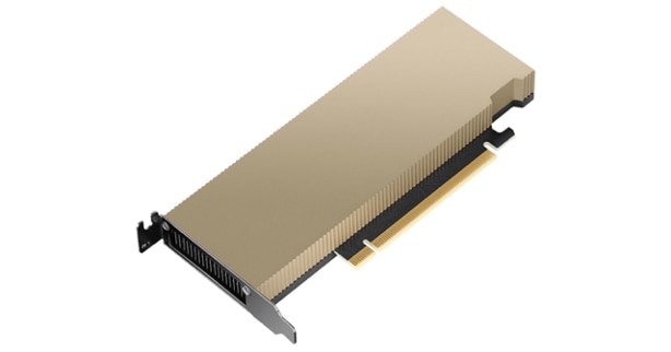
The NVIDIA L4 card is a single-slot PCI Express Gen4 card. It uses a passive heat sink for cooling, which requires system airflow to operate the card properly within its thermal limits. The NVIDIA L4 PCIe operates unconstrained up to its maximum thermal design power (TDP) level of 72 W to accelerate applications that require the fastest computational speed and highest data throughput at the edge.
The software layer of the NVIDIA AI platform, NVIDIA AI Enterprise, accelerates the data science pipeline and streamlines the development and deployment of production AI including generative AI, computer vision, speech AI and more. With over 50 frameworks, pre-trained models, and development tools, NVIDIA AI Enterprise is designed to accelerate enterprises to the leading edge of AI while simplifying AI to make it accessible to every enterprise.
Red Hat Enterprise Linux (RHEL) is the leading enterprise Linux platform, providing a stable, secure, and high-performance foundation for mission-critical workloads across physical, virtual, cloud, and edge environments. Built on open-source technologies with rigorous testing and certification, RHEL delivers predictable lifecycles, extensive hardware and software ecosystem compatibility, and enterprise-grade security features including SELinux, FIPS 140-2/140-3 compliance, and automated patching. As a subscription-based offering, RHEL includes access to Red Hat's global support organization, certified content repositories, and a comprehensive management toolset, making it the trusted choice for organizations requiring reliability, compliance, and long-term operational stability for their infrastructure deployments.
Podman is an open-source, daemonless container engine that provides a Docker-compatible command-line interface for building, running, and managing OCI-compliant containers and pods on Linux systems. Unlike traditional container runtimes, Podman operates without a central daemon, enabling rootless container execution for enhanced security and allowing you to run containers with standard Linux user privileges. As the default container runtime in Red Hat Enterprise Linux 8 and later, Podman seamlessly integrates with systemd for service management and supports Kubernetes-compatible pod definitions, making it ideal for both development and production container workloads.
Kernel-based Virtual Machine (KVM) is a Linux kernel module that transforms the Linux operating system into a type-1 hypervisor, enabling efficient virtualization of hardware resources. It leverages hardware virtualization extensions (such as Intel VT-x and AMD-V) to provide isolated virtual machines (VMs) with near-native performance. Each VM runs as a regular Linux process, benefiting from the host’s scheduler, memory management, and security mechanisms while maintaining strong isolation between guests. KVM also integrates with user-space tools like qemu-kvm and libvirt for VM lifecycle management, device emulation, and orchestration within larger infrastructure platforms.
OpenShift is a Kubernetes-based container application platform that automates the deployment, scaling, and management of containerized workloads. It provides an integrated developer and operations experience with built-in CI/CD, image management, and application templates. OpenShift adds enterprise features on top of Kubernetes, including advanced security, policy enforcement, and multi-tenancy. It supports hybrid and multi-cloud deployments, enabling consistent application environments across on-premises and public cloud infrastructure.
AI Inferencing at the Edge Landscape
AI inferencing at the edge enables real-time decision-making by processing data locally on devices, gateways, or micro data centers instead of relying solely on centralized cloud infrastructure. This decentralized approach is vital in latency-sensitive, bandwidth-constrained, or privacy-focused environments where immediate action is required, and network connectivity may be intermittent.
Key Use Cases and Benefits
● Industrial Automation and Predictive Maintenance - Enables real-time predictive maintenance by analyzing sensor data locally, reducing downtime and maintenance costs.
● Retail Intelligence and Smart Environments - Uses smart cameras and AI analytics at the edge to optimize customer experience, shelf layouts, and inventory management. Healthcare and Medical Diagnostics
● Healthcare Diagnostics: Processes patient vitals and imaging data on edge devices for instant diagnostics while maintaining data privacy.
● Security and Surveillance: Performs on-site AI-based threat detection, facial recognition, and anomaly monitoring with minimal latency.
● Smart Agriculture: Employs drones and sensors running AI models to assess crop health, detect pests, and optimize irrigation in real time.
Solution Design
This chapter contains the following:
● Single Node Red Hat Enterprise Linux Server with Podman
● Single Node Red Hat Enterprise Linux Server with KVM
● Single Node OpenShift Cluster
The Cisco Unified Edge with Red Hat solution provides an integrated architecture with Cisco and Red Hat technologies that demonstrate support for bare-metal, virtualized, and containerized workloads with high availability and server redundancy.
This chapter explains the key design requirement and various prerequisites for delivering this new solution, such as:
● Scalable design with the flexibility to add compute capacity, storage, or network bandwidth as needed.
● Modular design that can be replicated to expand and grow as the needs of the business grow.
● Flexible design that can support components beyond what is validated and documented in this guide.
● Simplified design with ability to automate and integrate with external automation and orchestration tools.
This Cisco Unified Edge solution comes as integrated stack with compute, storage and network and is connected to an external network domain.
Physical Components
The list of the required hardware components used to build a validated solution contains the Cisco Unified Edge components and the used network domain. You are encouraged to review your requirements and adjust the size or quantity of various components as needed.
Table 1. Unified Edge with Red Hat hardware components
| Component |
Hardware |
Comments |
| Cisco Unified Edge Chassis |
Cisco UCS XE9305 Chassis with two ECMCs. |
The Unified Edge Chassis with the ECMCs is the core of the solution design. |
| Cisco Unified Edge Compute nodes |
One to five Cisco UCS XE130c compute nodes. |
Your requirements will determine the amount of compute nodes required to build the solution. |
| Cisco Meraki Network Domain |
Meraki Switches (MS).
One or two Meraki Appliances (MX). |
Your requirements will determine the switch model and the amount of network ports and network speed required to build the solution. At least one Meraki MX device is required to remote locations to access the internet or the corporate network. |
| Cisco Catalyst Network Domain |
Cisco Catalyst 9000 series Switches.
One or two Cisco Catalyst 8000 series routers. |
Your requirements will determine the switch model and the amount of network ports and network speed required to build the solution. At least one Catalyst router is required to remote locations to access the internet or the corporate network. |
Physical Connectivity
Option 1: Simple HA Topology
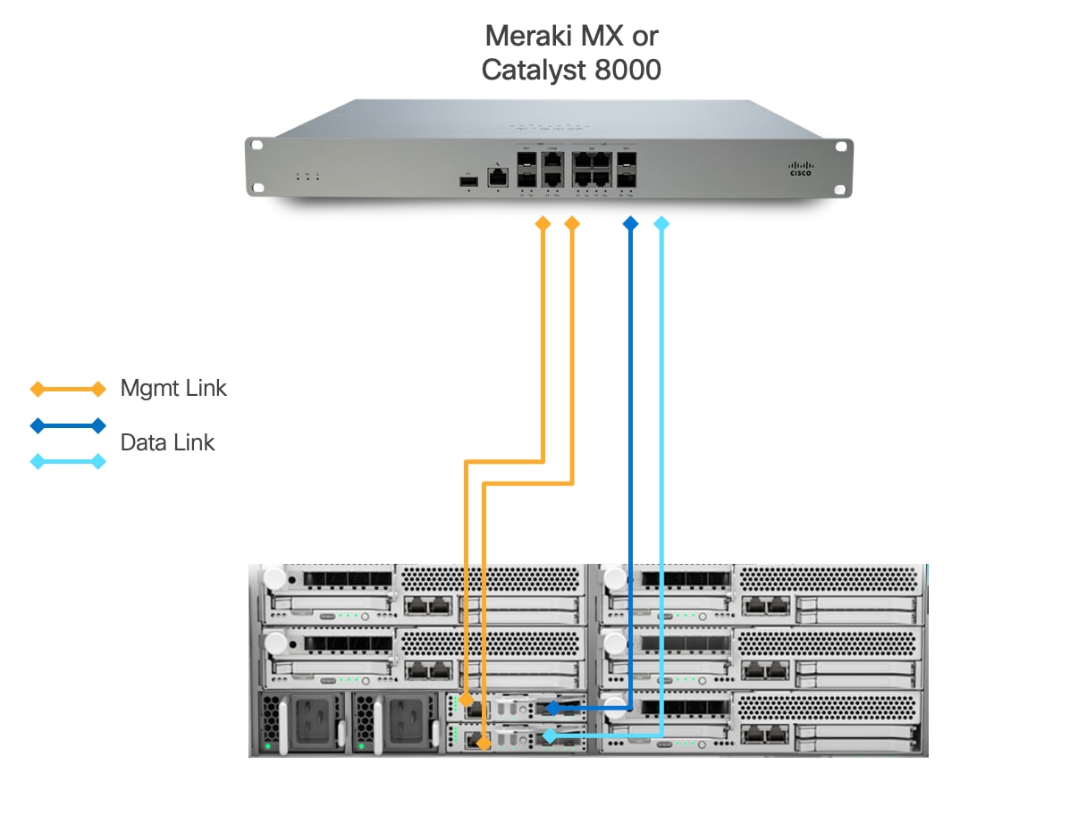
This design presents an approach for deploying Cisco UCS XE9305 chassis with a direct connection to a Meraki MX security appliance or Catalyst 8000.
● Each Cisco UCSXE-ECMC-G1 card's management port is connected to a Meraki MX or Catalyst 8000 via 1GbE links. The chassis and Cisco UCS XE130c M8 servers are still manageable in the event of a link failure.
● Cisco UCS XE9305 chassis is connected directly to a Meraki MX or Cisco Catalyst 8000 using a single 1/10GbE uplink from each UCSXE-ECMC-G1 card for data traffic.
◦ In the event of an ECMC failure, traffic can exit chassis through the uplink on second ECMC to avoid service interruptions.
This design explicitly implements an architecture with simple high availability (HA). The architecture eliminates intermediate switching layers, creating a simplified network path that reduces both physical space requirements and deployment complexity. This approach is particularly well-suited for edge locations where space constraints, operational simplicity, and cost-effectiveness are primary considerations.
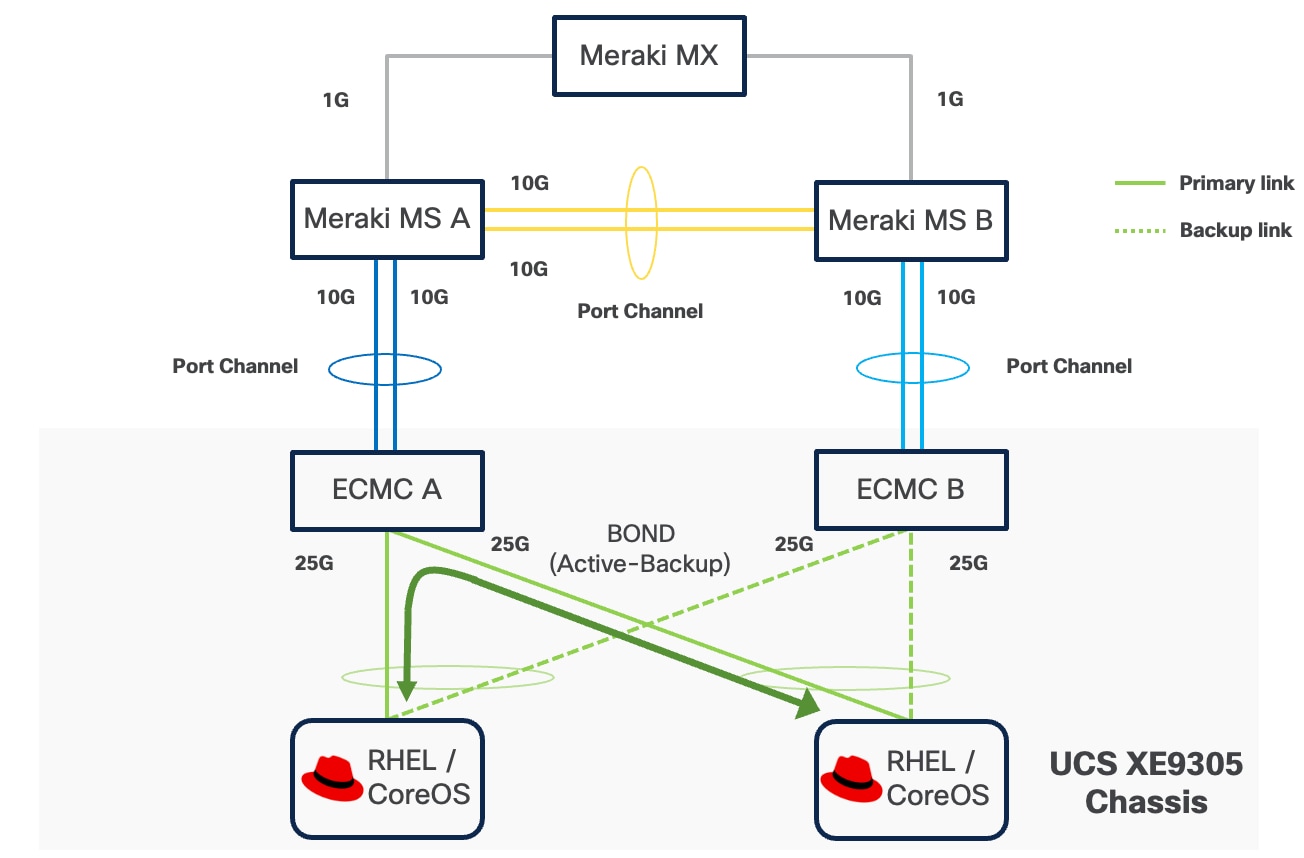
Option 2: Fully Redundant Topology
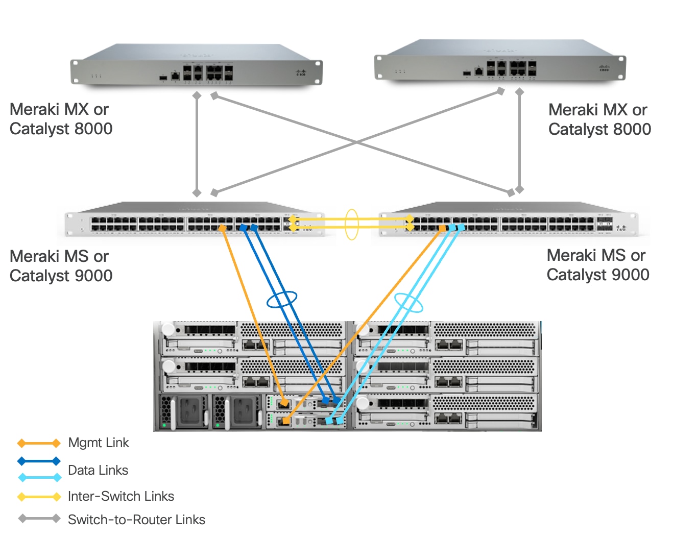
This architecture includes a Cisco UCS XE9305 chassis with up to 5 Cisco UCS XE130c M8 compute nodes.
● Cisco UCS XE9305 chassis is connected to a pair of switches (Meraki MS or Catalyst 9000). Each ECMC utilizes both of its 1/10 GbE uplinks, which are bundled together in a port-channel and connected to the same switch. A second ECMC is similarly connected to a different switch using another pair of bundled 1/10 GbE uplinks. This design delivers a combined bandwidth of 2Gbps or 20 Gbps per ECMC depending on connection type (1G or 10G), maximizing throughput for the connected devices.
◦ In the event of a single uplink failure, traffic continues to flow through the remaining uplink on the same ECMC.
◦ In the event of an ECMC failure, traffic can exit chassis through the uplinks on another ECMC card to avoid service interruptions.
◦ In the event of a switch failure, traffic can exit chassis from the uplink connected to the switch which is still fully functional.
● Each UCSXE-ECMC-G1’s management port is connected to a separate switch (Meraki MS or Catalyst 9000) via 1GbE links. The chassis and UCS XE130c M8 servers are still manageable in the event of a link failure or a switch failure.
● Two 1/10GbE links provide connectivity between two Cisco switches (Meraki MS or Catalyst 9000). Both links must be bundled as a port-channel for increased bandwidth and link redundancy.
● Each switch is connected to a pair of Meraki MX or Catalyst 8000 using redundant 1/10 GbE links for maximum redundancy between the switch layer and edge platforms.
● Meraki MXs or Catalyst 8000s use dedicated Internet/WAN ports to connect to ISP for Internet connectivity
The architecture is engineered to eliminate single points of failure across the edge network infrastructure. It creates a fully resilient path from the compute layer through the switching infrastructure to the security gateway and beyond to the wide area network. It provides continuous operation during link and component failures and is ideal for critical edge locations where business continuity requirements demand maximum uptime.
Option 3: Redundant Switching Topology
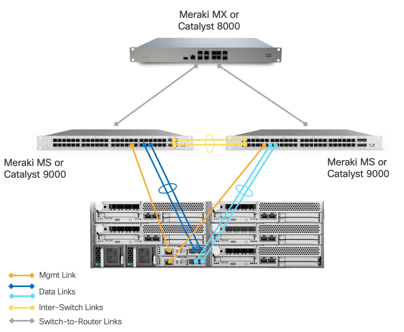
This architecture includes a Cisco UCSXE 9305 chassis with up to 5 Cisco UCSXE compute nodes. The main difference from the “Fully Redundant Topology” model is a single Meraki MX or Catalyst 8000 between edge network and WAN. This design provides maximum redundancy and network capacity at the switch layer. This design is particularly suitable for edge locations where multiple PoE-enabled devices (such as wireless access points, security cameras or sensors) need to be deployed, as the pair of switches provides the necessary PoE ports and power budget that a single Meraki Secure Appliance cannot adequately support out of the box. The switches handle layer 2 operations and PoE delivery efficiently, allowing the single Meraki Secure Appliance to focus on security functions and WAN connectivity without being overwhelmed by port density requirements.
The solution is validated using this option.
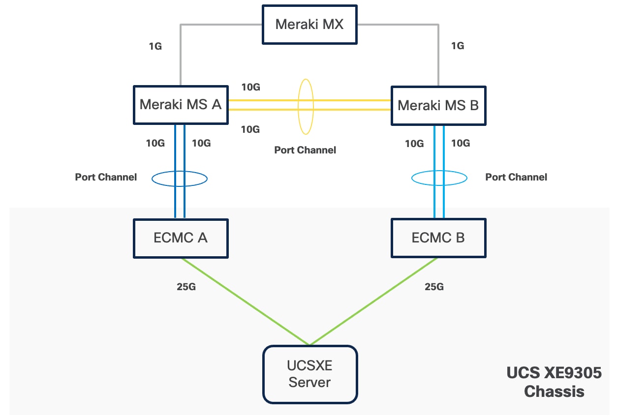
Connectivity Inside the Chassis
Cisco UCS XE9305 chassis in the design is populated with up to 5 Cisco UCS XE130c M8 servers. Each server is equipped with two 25 Gbps NICs connected to the midplane. One NIC links to an embedded 25 Gbps switch on one ECMC controller, and the other connects to a separate embedded 25 Gbps switch on a second ECMC controller.
The embedded switch modules within the Cisco UCS XE9305 chassis operate without Spanning Tree Protocol enabled, and no direct inter-switch link is provisioned between them, thereby eliminating the possibility of Layer 2 loops.
The operating system, whether RHEL or Red Hat CoreOS for OpenShift, can configure two network interface cards (NICs) either as independent interfaces or combined them into a single bonded interface. For the former case, the server has aggregated bandwidth of 50Gbps to the chassis. For bonded configurations, Cisco recommends using only the Active‑Backup mode to provide high availability and failover without link aggregation complexity. It is important to set the primary link on all servers to the same ECMC to keep Layer 2 traffic between servers inside the chassis as much as possible.
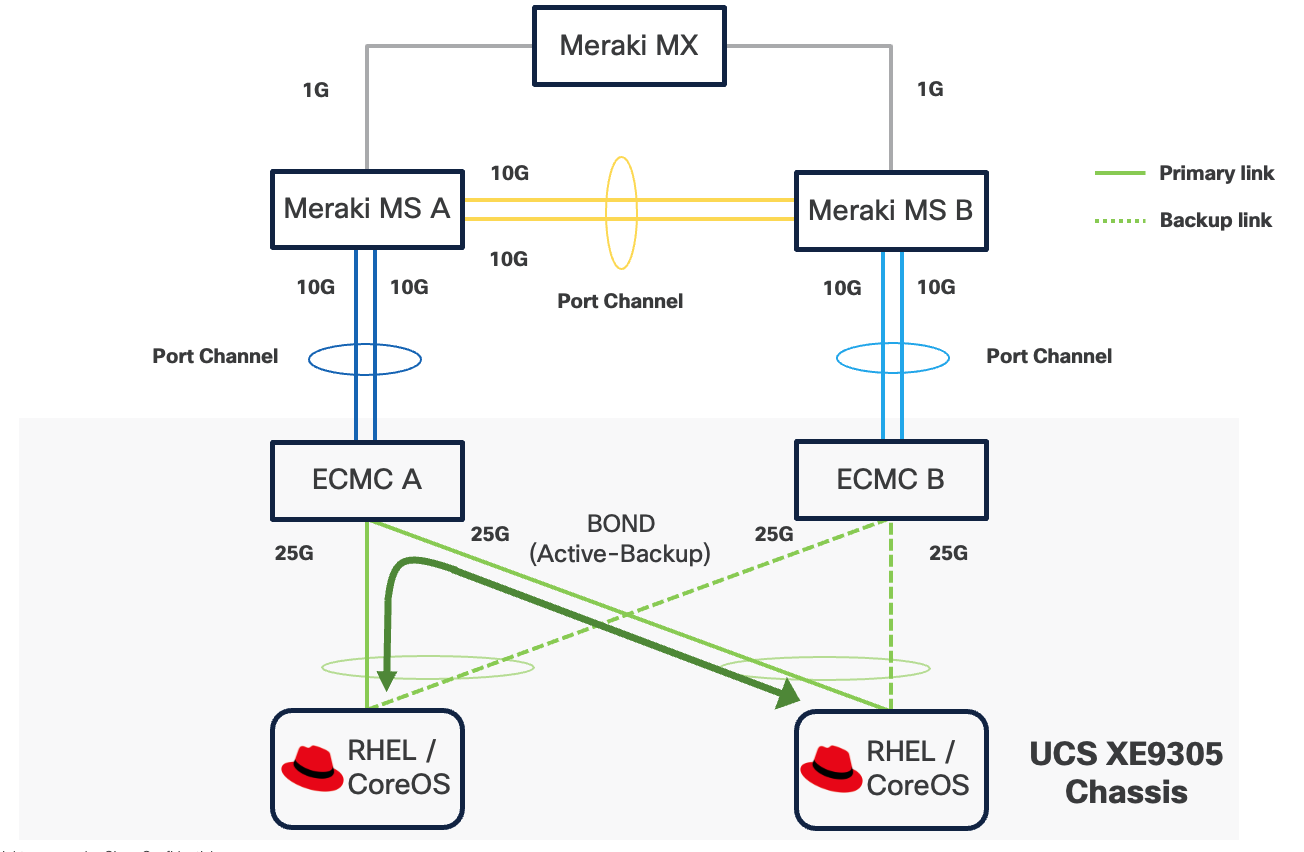
If a controller's uplink connectivity completely goes down, all associated NICs on the server side will also become unavailable to the operating system. This is controlled at ECMC level. At operating system level, if a bond interface is used, the operating system will automatically switch traffic from the failed link to the backup link, ensuring continuous connectivity.
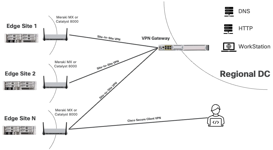
You can securely access services and workloads at edge locations using either the Cisco Secure VPN Client or a site-to-site VPN connection. In both scenarios, the VPN connection terminates at the Meraki MX or Catalyst 8000, which acts as the secure gateway to the edge network. The Cisco Secure VPN Client allows individual users to connect remotely from their devices, while a site-to-site VPN establishes a secure link between a regional data center and the edge location.
The Meraki MX or Catalyst 8000 is configured to push static routes to Cisco Secure VPN clients or to advertise edge networks to nearby data centers via site-to-site tunnels. These routes ensure that the subnets required to access Red Hat solutions and workloads at each edge location are reachable through the VPN tunnel.
Design Options
To address a broad range of deployment options, this design guide explains the following design options:
● Single-node Red Hat Enterprise Linux with Podman and KVM
Red Hat Enterprise Linux (RHEL) with Podman and KVM provides a lightweight, cost-effective solution for managing mixed container and virtual machine workloads at edge locations. Podman allows secure execution of containers without the overhead of a full container orchestration platform, while KVM (Kernel-based Virtual Machine) leverages RHEL's built-in hypervisor capabilities to run traditional virtual machines.
This approach delivers exceptional resource efficiency and is the right choice for a small number of simple, standalone applications, both VM or containerized, that do not need high availability, automated scaling or orchestration.
● Single-node Red Hat OpenShift Cluster with OpenShift Virtualization
In this architecture, the single node is responsible for hosting all core OpenShift services, including the Kubernetes control plane components as well as the workload execution typically performed by worker nodes.
OpenShift Virtualization feature, when enabled, can run KVM-based VMs as native Kubernetes objects, integrating them with the containerized ecosystem. This means both the orchestration and the user applications run on the same physical hardware without the need for a multi-node cluster footprint.
Additional worker nodes can be incorporated into the cluster to expand compute and storage capacity. This allows organizations to start with a minimal footprint and scale incrementally as business demands increase or as edge applications mature.
This approach is recommended for scenarios where occasional application or cluster downtime is acceptable and local data persistence is not essential. It is suitable for non-mission-critical workloads that do not require retention of sensitive data in the event of hardware failure.
● Compact Red Hat OpenShift Cluster with OpenShift Virtualization and OpenShift Data Foundation
This solution utilizes a three-node OpenShift cluster at the edge to deliver high availability (HA) for both the OpenShift control plane and application workloads.
In this deployment model, each of the three nodes is configured to function simultaneously as both a control plane and a worker node. This dual-role configuration optimizes resource utilization by allowing every node to run user workloads in addition to participating in cluster management.
The cluster's scalability is also preserved, as additional worker nodes can be integrated to expand compute and storage capacity as needed. This flexibility enables organizations to start with a minimal HA cluster footprint at the edge, while retaining the ability to adapt to increasing workload demands.
OpenShift Data Foundation provides robust data redundancy and resilience by distributing and replicating data across the cluster nodes, ensuring continuous data availability even in the event of node failures. This built-in redundancy enhances the overall reliability and durability of storage for critical workloads running on the cluster.
This architecture is particularly well-suited for edge environments where minimizing cluster or application downtime and maintaining local data persistence are essential requirements.
Table 2. Comparison of Multiple Red Hat Edge Solutions
| Component |
Single-node RHEL with Podman and KVM |
Single-node Red Hat OpenShift Cluster with OpenShift Virtualization |
Red Hat OpenShift Compact Cluster with OpenShift Virtualization and OpenShift Data Foundation |
| Orchestration |
Podman for containers and libvirt for VMs |
Kubernetes-native orchestration for both containers and VMs |
Kubernetes-native orchestration for both containers and VMs |
| Scalability (Application) |
Manual scaling only |
Limited by single node capacity |
Can scale to cluster capacity |
| Scalability (System) |
Limited: not designed for scale or orchestration. |
Can scale by adding worker nodes. |
Scalable: can add more worker nodes for extra capacity. |
| High Availability (Workload) |
Limited due to single point of failure |
Limited due to single point of failure |
Automatic rescheduling on node disruption |
| High Availability (System) |
None |
None |
Full HA with distributed control plane |
| Data Redundancy |
No built-in redundancy |
Single point of failure |
High redundancy with distributed storage |
| Best for |
Simple workloads that can accept disruption and don't require orchestration |
Workloads that can accept disruption but benefit from orchestration and centralized management. |
Mission-critical workloads needing HA and data persistence. |
Due to their unique characteristics, each of the three Red Hat solutions for managing container and VM workloads will be explored in dedicated chapters that follow. Each chapter contains an overview of the technologies involved, design considerations, and implications on infrastructure configuration, including compute, storage, and network on the Cisco Unified Edge platform.
Single Node Red Hat Enterprise Linux Server with Podman
Technical Overview
Podman
Podman is an open-source, daemonless container engine that allows you to build, run, and manage OCI-compliant containers and pods directly on Linux. Unlike Docker, Podman does not rely on a central background service with root privilege like Docker daemon, which improves security and simplifies integration with systemd. This design enables each container to be run directly as a separate user process without elevated privileges. Podman offers full compatibility with the familiar docker CLI, making it easy to adopt.
Netavark
Netavark and Aardvark dns are the networking components used by Podman as an alternative to the older CNI based setup. Netavark is a Rust based networking stack that configures container and pod networks without relying on a plugin model. It can create and manage network bridges, VLANs, macvlan/ipvlan interfaces, assign IP addresses, and configure firewall/NAT rules using nftables, enabling containers to reach each other and the internet.
Rootful and Rootless Container
Podman containers can run in two distinct modes: rootful and rootless:
● Rootful containers run with root privileges, meaning the Podman and containers execute as the root user (UID 0). This mode provides full system access, allows binding to privileged ports (below 1024), supports all networking modes including macvlan, and can perform system-level operations like mounting filesystems or modifying kernel parameters.
● Rootless containers, in contrast, run entirely under a regular user account without requiring root privileges, using user namespaces to map container UIDs to the host user's UID range (typically starting from 100,000). While rootless mode offers superior security by isolating containers from the host system and preventing privilege escalation attacks, it comes with limitations such as restricted networking options (no macvlan, limited to pasta or bridge modes), inability to bind to privileged ports directly, and reduced access to system resources.
Resource Requirements
Podman on Red Hat Enterprise Linux requires minimal system resources as it operates as a daemonless container engine that runs containers directly under user processes. The minimum hardware requirements for running RHEL with Podman on UCSXE servers are shown below. Additional CPU, memory, and storage resources are required to run containerized workloads with Podman.
● 2 CPUs
● 2GB of RAM
● 20GB disk space
Storage
Local Storage
Podman uses the host operating system's local storage subsystems to provide persistent data to containers. Unlike OpenShift, Podman does not include a built-in dynamic provisioning layer. Instead, containers consume storage directly from the host through bind mounts or Podman-managed named volumes, simplifying the storage design for single-host or small-scale deployments.
This design separates operating system functions from container workloads using dedicated physical storage devices:
● M.2 SSD drive with RAID 1, for the host operating system
● NVMe drive exclusively for container data, including images, volumes, and container storage
This separation allows container storage to be managed without affecting the system boot drive or host availability. Additionally, dedicated container storage facilitates operations such as backup and restore, by providing a clear boundary between system and application data.
Network Storage
Podman does not include built-in network storage management capabilities; instead, it relies on the host operating system to handle network storage protocols and mount operations. To use network storage with Podman containers, administrators must first configure and mount the network share at the host level using standard Linux tools and protocols (such as mounting an NFS export with the mount command or establishing an iSCSI session with iscsiadm). Once the network storage is mounted and accessible on the host filesystem, containers simply access the storage as if it were local filesystem storage.
Note: Fibre Channel is not validated in this design.
Network
Rootful Containers
The best networking option for a rootful Podman container depends on your needs for performance, host isolation, and network architecture.
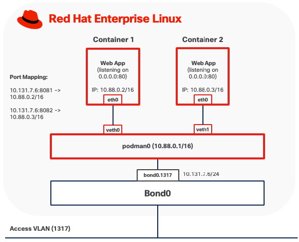
Option 1: Bridge Mode
Bridge mode is the default networking configuration for rootful Podman containers. In this mode, each container connects to a host-side Linux bridge, typically named podman0, which provides a private, isolated subnet for container communication.
● Outbound traffic from the container is forwarded through the bridge to the host network stack. Podman configures Network Address Translation (NAT) and masquerading rules using iptables or nftables, allowing the container to access external networks while remaining hidden behind the host's IP address.
● Inbound traffic requires explicit port mappings to reach containers. When a port is published using the “-p hostPort:containerPort” flag, Podman installs Destination NAT (DNAT) rules that rewrite packets arriving on the host's interface and port, delivering them to the container's private IP and port via the bridge. Without published ports, inbound connections from outside the host are blocked by default.
Note: When deploying custom Linux bridges for Podman containers, Spanning Tree Protocol (STP) must be disabled on the bridge interfaces.
Option 2: MACVLAN (Bridge) Mode
In MACVLAN mode, a rootful Podman container attaches directly to a physical network interface on the host by creating a lightweight MACVLAN subinterface. This subinterface is assigned a unique MAC address and receives an IP address on the same Layer 2 segment as the host. No NAT is involved. The container appears on the physical network as an independent device, as if it were directly connected to the same network switch.
● Outbound traffic from the container is transmitted through the MACVLAN interface directly onto the LAN using the container's own MAC and IP addresses. The MAC address is visible on upstream Meraki or Catalyst switches.
● Inbound traffic from other systems on the network is delivered directly to the container using standard IP routing, treating it like any other host on the subnet. No port forwarding or DNAT rules are required.
● Containers running in MACVLAN Bridge mode on the same host using the same parent interface can communicate directly with each other without traffic leaving the host.
● Containers cannot communicate directly with the host itself due to the limitation of MACVLAN
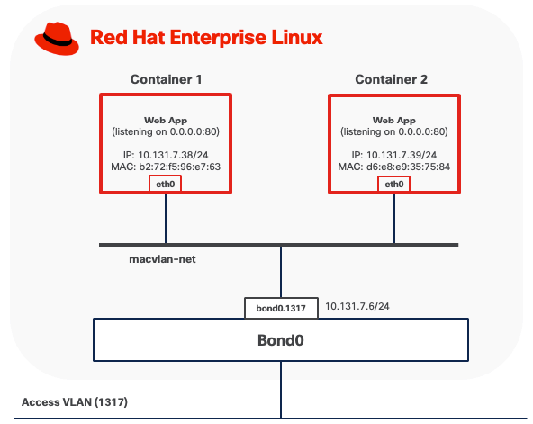
In this example, a rootful container (for example, container1) is attached to a Podman MACVLAN network that uses a VLAN subinterface bond0.1317 as the parent interface. The container is assigned its own MAC address on that tagged VLAN. From the perspective of the external network, rootful containers appear as independent hosts connected to the same Layer-2 broadcast domain as the parent interface.
MACVLAN mode requires that upstream network switches allow multiple MAC addresses to be learned on the same physical port. Because each container using MACVLAN is assigned a unique MAC address, the switch port connected to the host will observe multiple MAC addresses originating from a single physical connection, one for each container, plus the host's own MAC address if applicable. Upstream network switches must allow multiple MAC addresses to be learned on the same physical port. Some switches also enforce a per-port MAC address limit, such as the maximum number of MAC addresses that can be learned on a single port. Ensure this limit is set high enough to accommodate the host and all VMs.
For containerized workloads requiring networking capabilities beyond the above two options, consider deploying OpenShift as a comprehensive container orchestration platform.
Rootless Containers
Pasta provides user-mode networking for rootless Podman containers, operating entirely within the unprivileged user's namespace without requiring root privileges or elevated capabilities. Pasta creates a network namespace for the container and forwards traffic between the container and the host network stack through user-space socket operations.
By default, Pasta mirrors the IP configuration of the host interface that carries the default route. As a result, when multiple VLAN subinterfaces exist, only one can be used at container startup.
Rootless containers using Pasta can expose services externally through explicit port mappings. When a port is published (for example, -p 8080:80), Pasta forwards incoming connections from the host's network interface to the container's internal port using user-space socket operations. This port forwarding mechanism allows unprivileged users to publish services without administrative intervention. However, users cannot directly bind to privileged ports (below 1024) on the host without additional configuration. Remote clients access these services via the host's IP address and the published port, provided that host firewall rules allow inbound traffic from the appropriate networks.
For environments where rootless containers require more advanced capabilities, such as multiple network attachments, stronger isolation, or complex networking topologies, Red Hat OpenShift offers a more comprehensive solution.
Backup and Restore
Podman provides multiple backup and snapshot mechanisms, each serving different use cases and capturing different aspects of containerized workloads:
● Image Snapshots: Podman can create compressed archive snapshots of container images, preserving all layers and metadata.
● Container Exports: Podman can create filesystem snapshots of container instances capturing the current state of a container's filesystem but excludes runtime configuration and process states.
These backup operations can be performed using Podman CLI commands without requiring additional tools.
However, all backup data generated by these methods remains stored locally on the same server by default. If the server fails or becomes unavailable, all backup data is lost along with the original workloads. To ensure proper data protection, you must manually copy all backup artifacts (checkpoint files, exported images and container exports) to external storage systems such as network-attached storage, remote servers, or cloud storage services.
Management
Podman CLI
The Podman command-line interface (CLI) provides full container lifecycle management through a syntax compatible with the Docker CLI. You can use it to build, run, start, stop, inspect, and remove containers, as well as manage supporting resources such as images, volumes, networks, and pods.
At edge locations, the Podman CLI is available directly on the host for local troubleshooting and container management. For remote operations, you can securely access edge hosts over SSH, allowing Podman commands to be executed as if they run locally on the system.
Quadlets
Quadlets provide a declarative, systemd-native approach to container lifecycle management by utilizing specialized unit files (.container, .volume, .network, and .kube) that integrate seamlessly with systemd's service management framework. Quadlets leverage the quadlet generator to automatically translate declarative container specifications into the appropriate systemd service units at boot time or daemon reload. This architecture treats containers as first-class systemd services, enabling administrators to manage containerized workloads using standard Linux service management tools (systemctl, journalctl) while inheriting systemd's robust capabilities for dependency management, automatic restarts, resource control, and logging.
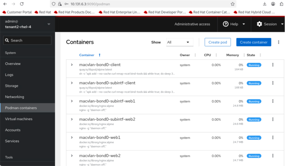
Red Hat Web Console
Red Hat Web Console, also known as Cockpit, is a web-based management interface that provides Podman container management capabilities. Cockpit offers a graphical alternative to Podman command-line operations.
The console displays real-time resource utilization metrics (CPU, memory, network, storage) for running containers, provides access to container logs, and enables management of container images, volumes, and networks.
This web interface is particularly valuable for edge locations where dedicated technical personnel may not be available on-site. You can manage containerized workloads at remote edge sites as long as you have network access to the server's IP address, eliminating the need for specialized command-line knowledge or physical presence at the edge location.
Cockpit requires the cockpit-socket service enabled and a firewall rule to allow TCP/9090. It runs as a system service accessible via HTTPS through any web browser locally or remotely.
The Cockpit Podman plugin must be installed (cockpit-podman package) to enable container management features within the web console.
Red Hat AI Inference Server
Deploying inferencing servers at edge locations enables organizations to process AI workloads locally, eliminating the latency, bandwidth costs, and connectivity dependencies associated with cloud-based inference. Edge inferencing with Red Hat AI Inference Server on compact infrastructure like Cisco Unified Edge with NVIDIA L4 GPU provides the computational power necessary for these demanding workloads at edge locations.
The Red Hat AI Inference Server is an enterprise-grade, fully supported product designed for container-based deployment across Red Hat Enterprise Linux and OpenShift environments. It leverages the vLLM open-source inference server for large language models (LLM). The vLLM runtime delivers the following validated capabilities:
● High-Throughput Serving: Optimized request scheduling and memory management for generative AI workloads
● Extended Context Windows: Support for large input sequences up to model-specific context limits
● Multi-GPU Distribution: Model tensor parallelism and pipeline parallelism for accelerated inference
● Continuous Batching: Dynamic request batching to maximize GPU utilization and reduce latency
The inference server integrates LLM Compressor capabilities to enable model optimization techniques that reduce computational requirements. Supported optimization methods include:
● Quantization: INT8 and INT4 weight quantization for reduced memory footprint
● Pruning: Structured and unstructured pruning to eliminate redundant parameters
● Knowledge Distillation: Model compression through teacher-student training approaches
The NVIDIA L4 GPU provides 24GB of GDDR6 memory, which represents the primary constraint for model selection. Model memory requirements include not only the base parameter weights but also Key-Value (KV) cache for managing context during inference, activation memory, and framework overhead. In general, small models (up to 7-8B parameters) can run comfortably using INT4, INT8, or FP8 quantization techniques applied to both weights and activations.
Consider models that have been pre-quantized and validated by Red Hat. The Red Hat AI repository on Hugging Face hosts a collection of models validated for compatibility with the inference server environment.
For the complete list, go to https://www.redhat.com/en/products/ai/validated-models.
See the Red Hat AI Inference Server document for more information about Red Hat AI Inference Server.
Software Components
Table 3 lists various software components used in the solution.
Table 3. Software components and versions
|
|
Component |
Verified version |
| Network |
Meraki MX68W |
MX 18.211.6 |
| Meraki MS (C9300L-24UXG-4X) |
CS 17.2.2 |
|
| Compute |
UCS XE9305 |
Infrastructure Bundle 6.0(1.251005) |
| UCSXE-130C-M8 |
Server Bundle 6.0(1.251026) |
|
| OS |
Red Hat Enterprise Linux |
9.6 |
| Orchestration |
Podman |
5.4.0 |
| AI Inference |
Red Hat AI Inference Server |
3.2.2 |
| NVIDIA Driver |
580.95.05 |
|
| CUDA |
13.0 |
Single Node Red Hat Enterprise Linux Server with KVM
Technical Overview
KVM
Kernel-based Virtual Machine (KVM) is a virtualization technology built directly into the Linux kernel that transforms RHEL into a Type-1 hypervisor. KVM leverages hardware virtualization extensions (Intel VT-x or AMD-V) to run multiple isolated virtual machines, each with its own operating system and dedicated virtual hardware resources.
KVM operates as a kernel module (kvm.ko) with processor-specific extensions (kvm-intel.ko or kvm-amd.ko), working in conjunction with QEMU (Quick Emulator), an open-source machine emulator and virtualizer, to provide device emulation and virtual machine management. KVM handles the CPU and memory virtualization by exposing the /dev/kvm interface, while QEMU emulates the rest of the machine hardware, including storage controllers, network adapters, and other I/O devices.
libvirt
libvirt is an open-source API, daemon, and management tool for managing virtualization platforms including KVM. It provides a unified interface for creating, configuring, and controlling virtual machines through the libvirtd daemon. libvirt abstracts the complexity of direct QEMU/KVM interaction, offering consistent management capabilities across different virtualization technologies.
Rootful and Rootless Virtual Machines
Similar to containers, KVM virtual machines managed by libvirt can operate in two distinct modes: rootful and rootless.
Rootful VMs run under the system-wide libvirtd daemon (system mode). While libvirtd itself requires root privileges to configure system resources, manage networking, and set up device access, the actual VM processes run with the reduced privileges of the QEMU user for security isolation. This architecture provides full access to system-wide resources including advanced networking configurations (MACVLAN, Linux bridge attachments), PCI device passthrough for GPUs or storage controllers, shared storage pools, but executed within the security context of the unprivileged QEMU user.
Rootless virtual machines run under a user-specific libvirt session (session mode) without requiring root privileges. Each user runs their own libvirt instance within their user session, and VMs execute with the privileges of that user account. While rootless mode offers improved security by limiting the impact of potential VM escape vulnerabilities, it comes with significant limitations including restricted networking options, no access to bridge or macvtap networking without additional configuration, inability to perform PCI passthrough, restricted storage pool access (limited to user-owned directories), and no ability to auto-start VMs at system boot.
Resource Requirements
The validation of Unified Edge with KVM on RHEL was done with Cisco UCS XE130c M8 servers. It is essential to size the solution and all its components according to the specific needs of each customer. Since there is no universal sizing approach, detailed sizing and performance testing are not included in the validation process. For example, at the Cisco UCS level, you can choose servers with different processor core counts and memory configurations. This flexibility allows optimization of the servers for the best cost-to-performance balance. The same approach applies to storage and other components within the solution.
Table 4. Cisco UCS XE130c M8 Compute Nodes Configuration Options
| Server Model |
CPU |
Boot Storage |
| UCSXE-130C-M8-12 |
1 x GENUINE INTEL(R) XEON(R), 12 Cores |
RAID1 on local SSD |
| UCSXE-130C-M8-20 |
1 x GENUINE INTEL(R) XEON(R), 20 Cores |
RAID1 on local SSD |
| UCSXE-130C-M8-32 |
1 x GENUINE INTEL(R) XEON(R), 32 Cores |
RAID1 on local SSD |
KVM is integrated into the Linux kernel and has minimal overhead. The minimum hardware requirements for RHEL server running KVM include:
● A 64-bit x86 processor with hardware virtualization extensions (Intel VT-x or AMD-V) is mandatory, which should be enabled in BIOS/UEFI via Server Profile on Intersight
● If PCI passthrough is desired, for example, to enable GPU in VM, hardware support for IOMMU (Intel VT-d) must be enabled in both BIOS and the kernel parameters
● 2 CPUs on the host
● 2 GB of RAM for the host
● 20 GB disk space for the host
Additional CPU, memory, and storage resources are required to run virtualized workloads with KVM. While RHEL provides features to support CPU and memory oversubscription for VM, it is important to note that this guideline is not included in the validated design documentation. For further details on resource allocation and best practices regarding CPU and memory subscription, see the official guidelines here: https://docs.redhat.com/en/documentation/red_hat_enterprise_linux/9/html/configuring_and_managing_virtualization/optimizing-virtual-machine-performance-in-rhel_configuring-and-managing-virtualization
Storage
Local Storage
KVM uses the host operating system’s local storage to provide persistent disk space for virtual machines. Libvirt manages storage through storage pools. For local storage, the most common pool types are directory-based pools and logical volume (LV) pools. The validated design separates operating system functions from virtual machine workloads using dedicated physical storage devices:
● M.2 SSD drive with RAID 1, for the host operating system
● NVMe drive exclusively for virtual machine, such as storage pools, for both rootful and rootless VMs
This separation prevents storage exhaustion by ensuring that virtual machine disk usage cannot fill the OS disk, which keeps the host system operational even if VM storage reaches capacity. It also enables independent management where the dedicated VM storage device can be managed separately for operations such as backup, restore, and capacity expansion without affecting the host operating system.
Network Storage
KVM and libvirt rely on the host operating system to handle network storage protocols. To use network storage with VMs, administrators must first mount the network share on the host using standard Linux tools. Once mounted, the share can be configured as a libvirt storage pool for VM disk allocation. Virtual machines access network storage through standard virtual disk interfaces and remain unaware that the underlying storage is network-attached.
When deploying network storage at edge locations, factors such as network bandwidth, latency, and reliability should be carefully evaluated to ensure acceptable VM performance and availability.
Note: Fibre Channel is not validated in this design.
Network
Rootful Virtual Machines
Rootful virtual machines offer multiple networking options depending on requirements for performance, network integration, and isolation.
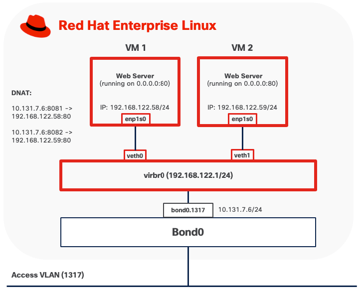
Option 1: NAT Mode
NAT mode is the default networking configuration for rootful KVM virtual machines. In this mode, libvirt creates a virtual bridge (typically named virbr0) that acts as a virtual switch, connecting virtual machines to a private subnet (commonly 192.168.122.0/24). The bridge includes an integrated DHCP server (dnsmasq) that automatically assigns IP addresses to virtual machines and provides DNS resolution services.
● Outbound traffic from virtual machines passes through the bridge to the host's network stack. libvirt configures Network Address Translation (NAT) rules using iptables or nftables, allowing VMs to access external networks while remaining hidden behind the host's IP address. From the external network's perspective, all VM traffic appears to originate from the host.
● Inbound traffic requires explicit port forwarding rules to reach virtual machines. Without port forwarding configuration, external systems cannot initiate connections to VMs in NAT mode, as the VMs exist on a private network behind the host's NAT gateway.
Option 2: MACVLAN
MACVLAN mode connects virtual machines directly to physical networks without requiring a traditional Linux bridge. Each virtual machine is assigned a unique MAC address and receives an IP address on the same subnet as the parent network, appearing as an independent device on the network.
● Outbound traffic from virtual machines is transmitted directly to the physical switch through the parent physical interface using the VM's own MAC and IP addresses. The MAC address is visible on upstream network switches.
● Inbound traffic from external systems is delivered directly to the virtual machine using standard IP routing. No port forwarding or NAT configuration is required, with service accessibility controlled only by network and VM firewall rules.
● VMs running in MACVLAN Bridge mode on the same host using the same parent interface can communicate directly with each other without traffic leaving the host.
● VMs cannot communicate directly with the host itself due to the limitation of MACVLAN.
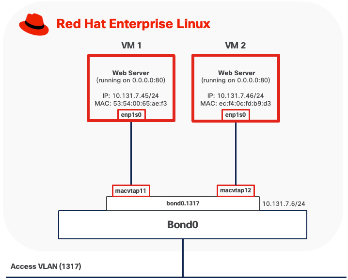
When MACVTAP is attached to a VLAN subinterface (for example, bond0.1317), the upstream switch port must be configured as a trunk port with the corresponding VLAN allowed. The switch must permit tagged traffic for all VLANs that the virtual machines will use. If MACVTAP uses the base physical interface (for example, bond0) for untagged traffic, the switch port should be configured with the appropriate native VLAN or as an access port on the desired VLAN.
Because each virtual machine using MACVTAP is assigned a unique MAC address, the switch port connected to the host will observe multiple MAC addresses originating from a single physical connection, one for each VM, plus the host's own MAC address if applicable. Upstream network switches must allow multiple MAC addresses to be learned on the same physical port. Some switches also enforce a per-port MAC address limit, such as the maximum number of MAC addresses that can be learned on a single port. Ensure this limit is set high enough to accommodate the host and all VMs.
Option 3: Per-VLAN Linux Bridge
This mode connects virtual machines directly to the host's physical network by creating a Linux bridge that includes both virtual machine interfaces and a physical network interface. In this configuration, VMs obtain IP addresses on the same subnet as the physical network and appear as independent hosts on the network.
To implement this design option, you need to create a Linux bridge (such as br-workload) on the host and add an interface (for example, bond0.1318 for VLAN-tagged traffic) as a bridge member. When a VM starts, libvirt creates a tap device for the VM's network interface and attaches it to the bridge. The bridge forwards traffic between VMs and the physical network at Layer 2, making VMs directly accessible from the external network.
● Outbound traffic from virtual machines is forwarded through the bridge directly to the physical network using the VM's own MAC and IP addresses. No address translation occurs.
● Inbound traffic from external systems is delivered directly to virtual machines using standard IP routing, treating VMs as independent hosts on the network. No port forwarding or NAT configuration is required, as each VM has a routable IP address on the physical network subnet. Service accessibility is subject to standard network and VM firewall rules.
● VMs connected to the same Linux bridge can communicate directly with each other through the bridge without traffic leaving the host.
● The host can access VMs directly through the Linux bridge.
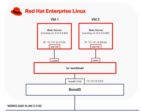
The port on the upstream switch must be configured as a trunk port if the Linux bridge is attached to a VLAN sub-interface. Spanning Tree Protocol (STP) must be disabled on the Linux bridge.
Rootless Virtual Machines
Rootless virtual machines have significantly limited networking capabilities compared to rootful VMs due to the lack of root privileges required for advanced network configuration. Networking typically uses user-mode stacks such as slirp or passt.
Due to their networking limitations and restricted access to system resources, rootless virtual machines are not recommended for production deployments and are not covered by this validated design.
For use cases requiring networking capabilities beyond bridge, Per-VLAN Linux bridge, and MACVLAN modes, consider deploying OpenShift Virtualization.
Backup and Restore
KVM virtual machine backup and restore operations require consideration of both the virtual machine disk images and their associated configuration data.
● Live snapshots: For virtual machines using qcow2 disk format, KVM can create a point-in-time copy of the VM's disk state while the VM continues to operate.
● Offline backups: It involves shutting down the VM and copying its disk image files and configuration data. This method is compatible with any supported disk format (raw, qcow2, vmdk) and can be performed using standard file system tools such as cp, rsync or scp included with RHEL.
● Block-level backups: For virtual machines using LVM-based storage pools, administrators can leverage LVM snapshots to create point-in-time, consistent copies of VM disks without downtime. Once the snapshot is established, data can be backed up from the snapshot logical volume using various methods such as dd for raw block copying or mounting the snapshot to access individual files through standard file system tools. The backup data is then transferred to NAS using network transfer protocols like SSH/SCP or rsync.
Sufficient network bandwidth is critical to ensure backup and restore operations complete in a timely manner, especially with large VM images or frequent backup schedules. Low network latency is important to minimize delays and reduce the risk of backup failures, particularly during high-throughput operations.
Management Tools
virt-install
virt-install is a command-line tool for creating and provisioning new KVM virtual machines. It automates VM definition and OS installation from various sources including ISO images, network repositories, or existing disk images.
virt-install command can run directly on the KVM host with appropriate permissions. Remote provisioning requires SSH access and appropriate permissions on the remote system, plus access to installation media (ISO files or network sources accessible from the remote host)
virsh
virsh is the primary command-line interface for managing KVM virtual machines through libvirt. It provides comprehensive VM lifecycle management (start, stop, reboot, delete), configuration editing, and management of storage pools, virtual networks, and snapshots.
virsh can be used both locally and connect to remote KVM hosts using SSH-based connections without requiring additional tools.
Red Hat Web Console
Red Hat Web Console, also known as Cockpit, provides a web-based interface for managing KVM virtual machines through the “cockpit-machines plugin.” The web interface offers graphical alternatives to command-line operations, making virtual machine management accessible to users who prefer visual tools.
Cockpit runs as a system service on TCP port 9090 and can be accessed locally or remotely using HTTPS. For remote access, ensure that firewall rules permit TCP port 9090 only from trusted management networks.
Software Components
Table 5 lists various software components used in the solution.
Table 5. Software components and versions
|
|
Component |
Validated version |
| Network |
Meraki MX68W |
MX 18.211.6 |
| Meraki MS (C9300L-24UXG-4X) |
CS 17.2.2 |
|
| Compute |
UCS XE9305 |
Infrastructure Bundle 6.0(1.251005) |
| UCSXE-130C-M8 |
Server Bundle 6.0(1.251026) |
|
| OS |
Red Hat Enterprise Linux |
9.6 |
| Orchestration |
KVM |
9.1.0 |
Technology Overview
Red Hat OpenShift Container Platform (OCP)
The Red Hat OpenShift Container Platform (OCP) is a container application platform that brings together CRI-O and Kubernetes and provides an API and web interface to manage these services. CRI-O is an implementation of the Kubernetes CRI (Container Runtime Interface) to enable using Open Container Initiative (OCI) compatible runtimes.
OCP allows you to create and manage containers. Containers are standalone processes that run within their own environment, independent of operating system and the underlying infrastructure. OCP helps developing, deploying, and managing container-based applications. It provides a self-service platform to create, modify, and deploy applications on demand, thus enabling faster development and release life cycles. OCP has a microservices-based architecture of smaller, decoupled units that work together.
OpenShift Virtualization
OpenShift Virtualization is a feature of Red Hat OpenShift Container Platform that enables you to run and manage virtual machines (VMs) alongside containerized applications within the same Kubernetes-based infrastructure. Built on the open-source KubeVirt technology, OpenShift Virtualization extends the capabilities of OpenShift to support traditional virtualized workloads.
● Creation, configuration, and management of Linux and Windows virtual machines as native Kubernetes resources.
● Multiple access and administration interfaces, including web-based consoles (VNC and serial console), SSH, and remote desktop protocols (RDP for Windows VMs).
● Flexible management of VM resources, including attachment and configuration of multiple network interface controllers (NICs). Storage can be provisioned from Kubernetes persistent volumes, enabling integration with enterprise storage solutions and cloud-native storage providers.
● Live migration of virtual machines between OpenShift nodes with zero downtime*
Note: * Not supported on Single-Node OpenShift Cluster

Logical Volume Manager (LVM) Storage
LVM Storage is a local storage solution for OpenShift on a single-node cluster, delivering high-performance block storage for both containerized applications and virtual machine workloads. Built on and integrated through the Logical Volume Manager Storage (LVMS) Operator, this solution enables organizations to efficiently utilize locally attached storage devices on OpenShift cluster nodes. The LVM Operator uses the TopoLVM CSI driver to provision local storage, allowing dynamic creation and management of persistent volumes while maintaining consistency with OpenShift's storage abstraction layer.
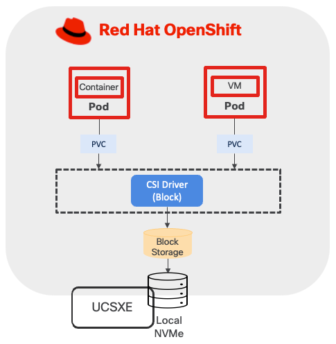
This validated design implements LVM Storage as the primary storage solution for single-node OpenShift clusters, addressing use cases requiring low-latency, high-throughput local storage access without dependencies on external shared storage infrastructure.
Sizing
CPU/Memory
When running OpenShift single-node cluster, the minimal resource requirements for the node are shown below.
● 8 CPU cores
● 16 GB RAM
● 120GB disk space
When deploying containers and virtual machines on top of OpenShift, sizing must account for multiple factors, which include, but are not limited to:
● Overhead of OpenShift Virtualization
● CPU and memory for VM workloads and the amount of overhead for the VMs
● CPU and memory request/limits for containerized workload
● Special resources may be allocated to VM such as dedicated CPUs, GPU, and so on.
For more information, see the Red Hat document OpenShift Virtualization Cluster Sizing Guide.
If more resources are needed, consider OpenShift compact cluster.
Storage
This design separates operating system functions from container workloads using dedicated physical storage devices:
● M.2 SSD drive with RAID 1, is used for several important functions beyond installing RHCOS. This includes runtime storage for OS and platform features (images, log data, and so on), ephemeral volumes, etcd storage for control plane nodes, kubelet data, and more.
● NVMe drives are exclusively for LVM. LVM consumes the entire NVMe capacity to provision block storage services for both containerized and virtualized applications.
This storage design follows Cisco best practices for converged infrastructure deployments, providing both operational reliability through RAID protection and optimal performance through dedicated NVMe allocation for persistent storage workloads.
The LVM storage configuration creates a volume group utilizing all available unused disks and provisions a single thin pool sized at 90 percent of the total volume group capacity, with the remaining 10% reserved as free space to accommodate thin pool expansion when required. Thin pool utilization must be monitored closely to prevent storage exhaustion and workload disruptions.
Network
VLAN Usage
| VLAN ID |
Name |
Usage |
| 1315 |
OOB-MGMT-VLAN |
Out-of-band management VLAN to connect management ports for various devices. |
| 1316 |
IB-MGMT-VLAN |
In-band management VLAN utilized for all in-band management connectivity. Native VLAN. |
| 1317 |
ACCESS-VLAN |
Access for OpenShift hosts. |
| 1318 |
WORKLOAD-VLAN |
Dedi Dedicated VLAN for VM secondary network. |
Some of the key highlights of VLAN usage are as follows:
● VLAN 1315 allows you to manage and access out-of-band management interfaces of various devices and is brought into the infrastructure to allow IMC access to the Unified Edge ECMC or Catalyst devices. Interfaces in this VLAN are configured with MTU 1500.
● VLAN 1316 served as in-band management VLAN which is required to use vMedia policy and CIMC-Mounted ISO images inside Unified Edge. Interfaces in this VLAN are configured with MTU 1500.
● VLAN 1317 is used to access OpenShift hosts. Interfaces in this VLAN are configured with MTU 1500.
● VLAN 1318 is added to provides an additional interface that connects virtual machines to dedicated or isolated network. Interfaces in this VLAN are configured with MTU 1500.
At least one VLAN-ID must be specified inside Cisco Unified Edge and mapped as Native-VLAN to allow network traffic to the next-hop switch without VLAN tagging.
OpenShift Cluster and Service Networks
During OpenShift installation, two primary internal IP subnets must be configured:
● Cluster network CIDR (also called the Pod network), default to 10.128.0.0/14, provides IP addresses to pods and VMs running in the cluster. OpenShift allocates each pod a cluster IP address for Pod-to-Pod communication. With OpenShift Virtualization, VMs are also deployed as pods and receive their own cluster IP addresses.
● Service network CIDR, defaults to 172.30.0.0/16, allocates virtual IP addresses to Services for stable endpoint access.
The Cluster network and Service network must not overlap with each other. The Cluster network IP range should not overlap with other IP space external to the cluster, which VMs or Pods may need to connect to. This includes the subnet where OCP nodes reside. For example, if three OCP nodes are configured with IP address in the subnet 10.131.6.0/24, then Cluster network must be changed from the default CIDR, which is 10.128.0.0/14, to another one, such as 10.120.0.0/14.
OpenShift Virtualization Related Network - VM Secondary Network
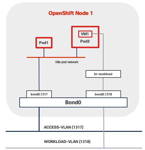
VM Secondary Networks in OpenShift Virtualization provide additional network interfaces beyond the default pod network, enabling virtual machines to connect directly to external Layer 2 or Layer 3 networks. This capability leverages Multus CNI (Container Network Interface) to attach VMs to multiple networks simultaneously while maintaining the pod network for Kubernetes cluster communication.
When using this architecture, consider the following network implications:
● VLAN reserved for VM secondary network must be present across the entire data path across the network infrastructure. This includes:
◦ BOND interface, such as bond0.1318 in Figure 22.
◦ Network segment between UCSXE servers and ECMCs
◦ Network segment between ECMCs and upstream switches if Layer 2 connectivity between VMs and external network services is desired.
◦ All network segments from ECMCs to edge platforms if Layer 3 routing is required
● Spanning Tree Protocol (STP) must be disabled if Linux Bridge or OVS (Open Virtual Switch) are used to connect VM secondary network to underlying infrastructure.
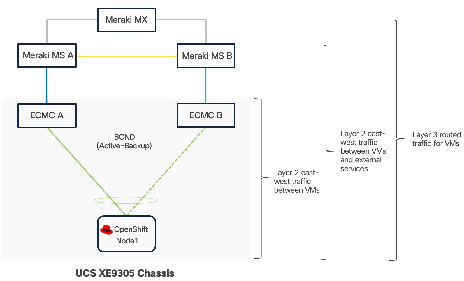
Management
OpenShift Web Console
The OpenShift Web Console is a browser-based management interface that provides access to cluster operations and monitoring capabilities. You can access the console through standard web browsers over HTTPS connections, enabling remote management from any location with network connectivity to the cluster. The interface supports common administrative tasks including application deployment, resource scaling, configuration management, and cluster monitoring. The OpenShift Web Console also provides access to virtualization features, allowing administrators to create, start, stop, migrate, and delete virtual machines from any location with network connectivity to the cluster.
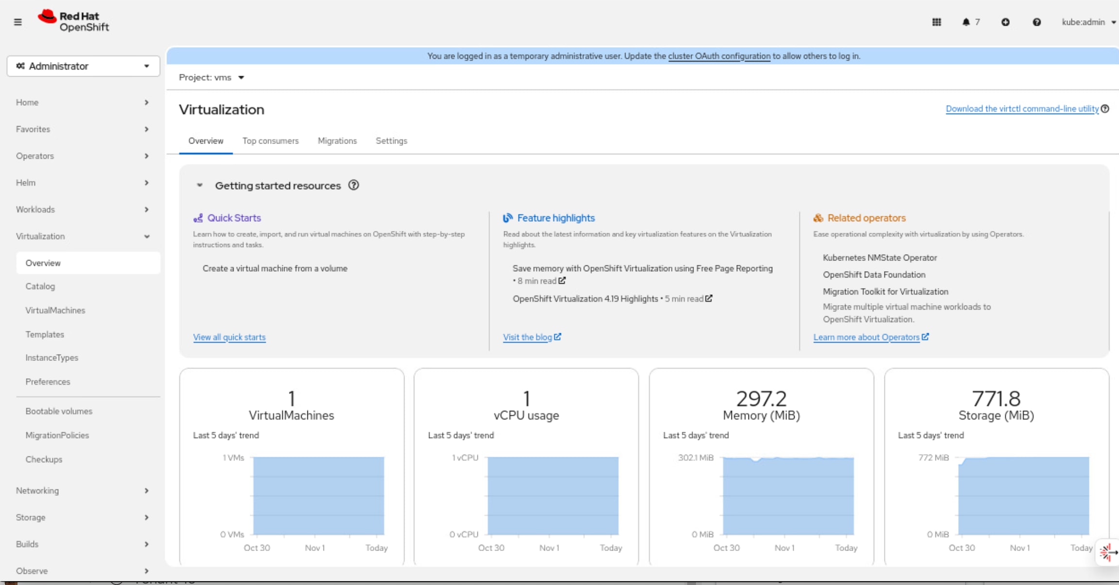
OpenShift Command Line Interface (oc)
The OpenShift Command Line Interface (oc) is a powerful tool to manage OpenShift clusters, containers and virtual machines on the OpenShift platform through a unified interface. It includes all kubectl's functionality plus additional commands for OpenShift-specific features. For containers, oc provides comprehensive capabilities including deploying applications, managing pods and deployments, scaling workloads, viewing logs, executing commands inside containers, and managing resources like services, routes, and config maps. With OpenShift Virtualization, the oc tool extends its functionality to manage virtual machines alongside containerized workloads, allowing you to create, start, stop, and delete VMs, manage VM templates, handle storage volumes, and perform live migrations.
Virtctl
The virtctl command-line utility manages virtual machines in the OpenShift Virtualization environment. The tool provides commands for common VM operations including starting, stopping, pausing, and live migrating virtual machines between cluster nodes through the Kubernetes API. Virtctl also supports advanced functionality such as accessing VM serial consoles for troubleshooting and uploading virtual disk images to the cluster for VM provisioning.
Infrastructure Service
DNS
The Domain Name System (DNS) serves as a foundational component for OCP Platform operations and is critical for maintaining cluster availability. The DNS servers may reside on the internet, in a public cloud, at an edge data center, or at a headquarters location. Ensure that all OpenShift nodes always maintain continuous network connectivity to the DNS servers.
Configure DNS zones to support both forward (name-to-IP) and reverse (IP-to-name) lookups for a defined set of DNS entries as listed in the following Table 7.
Table 7. DNS Entries for OpenShift Single-Node Cluster
| Components |
Required Records |
Record Type |
Description |
| OpenShift API (External) |
api.<cluster_name>.<base_domain> |
A/AAAA, CNAME, and PTR |
Resolvable by external clients and the SNO node. |
| OpenShift API (Internal) |
api-int.<cluster_name>.<base_domain> |
A/AAAA, CNAME, and PTR |
Resolvable by the SNO node. |
| Application Routes |
*.apps.<cluster_name>.<base_domain> |
A/AAAA, CNAME, and PTR |
It ensures that applications are accessible both externally and from within the cluster. |
| OpenShift Nodes |
<node-name>.<cluster_name>.<base_domain> |
A/AAAA, CNAME, and PTR |
Identifies the SNO node. |
DHCP
To maintain predictability and avoid IP conflicts, it is recommended to use DHCP reservations.
NTP
For many reasons, including authentication and log correlation, it is critical that all unified edge components are properly synchronized to multiple, redundant NTP time sources.
Load Balancer
OpenShift supports both internal and external load balancer configurations. It's common to use a built-in VIP-based internal load balancer. It removes the need for additional external load balancer infrastructure. If containerized or virtualized applications requires heavy use of the OpenShift Route/ingress capabilities, external load balancers must be provided.
Remote Access
For external access to OpenShift management interfaces and deployed applications, ensure the following TCP ports are accessible:
● OpenShift API Server (TCP 6443) is required for, OpenShift web console, oc and virtctl operations.
● Ingress Controller Access (TCP Ports 443 and 80) provides external access to the OpenShift web console user interface, deployed HTTP and HTTPS applications exposed through OpenShift Routes.
● Service-Specific Access for non-HTTP applications requires configuration of OpenShift Services with type LoadBalancer or NodePort. LoadBalancer services provision external load balancer resources that expose applications on specific TCP or UDP ports with dedicated IP addresses. NodePort services expose applications on high-numbered ports across all cluster nodes.
Software Components
Table 8 lists various software components used in the validated solution.
Table 8. Software components and versions
|
|
Component |
Validated version |
| Network |
Meraki MX68W |
MX 18.211.6 |
| Meraki MS (C9300L-24UXG-4X) |
CS 17.2.2 |
|
| Compute |
UCSXE-9305 |
Infrastructure Bundle 6.0(1.251005) |
| UCSXE-130C-M8 |
Server Bundle 6.0(1.251026) |
|
| Orchestration |
Red Hat OpenShift |
4.19.13 |
| Red Hat OpenShift Virtualization |
4.19.12 |
Technology Overview
Red Hat OpenShift Container Platform (OCP)
The Red Hat OpenShift Container Platform (OCP) is a container application platform that brings together CRI-O and Kubernetes and provides an API and web interface to manage these services. CRI-O is an implementation of the Kubernetes CRI (Container Runtime Interface) to enable using Open Container Initiative (OCI) compatible runtimes.
OCP allows you to create and manage containers. Containers are standalone processes that run within their own environment, independent of operating system and the underlying infrastructure. OCP helps developing, deploying, and managing container-based applications. It provides a self-service platform to create, modify, and deploy applications on demand, thus enabling faster development and release life cycles. OCP has a microservices-based architecture of smaller, decoupled units that work together.
OCP Compact cluster utilizes three nodes to deliver high availability (HA) for both the OpenShift control plane and application workloads.
In this deployment model, each of the three nodes is configured to function simultaneously as both a control plane and a worker node. This dual-role configuration optimizes resource utilization by allowing every node to run user workloads in addition to participating in cluster management.
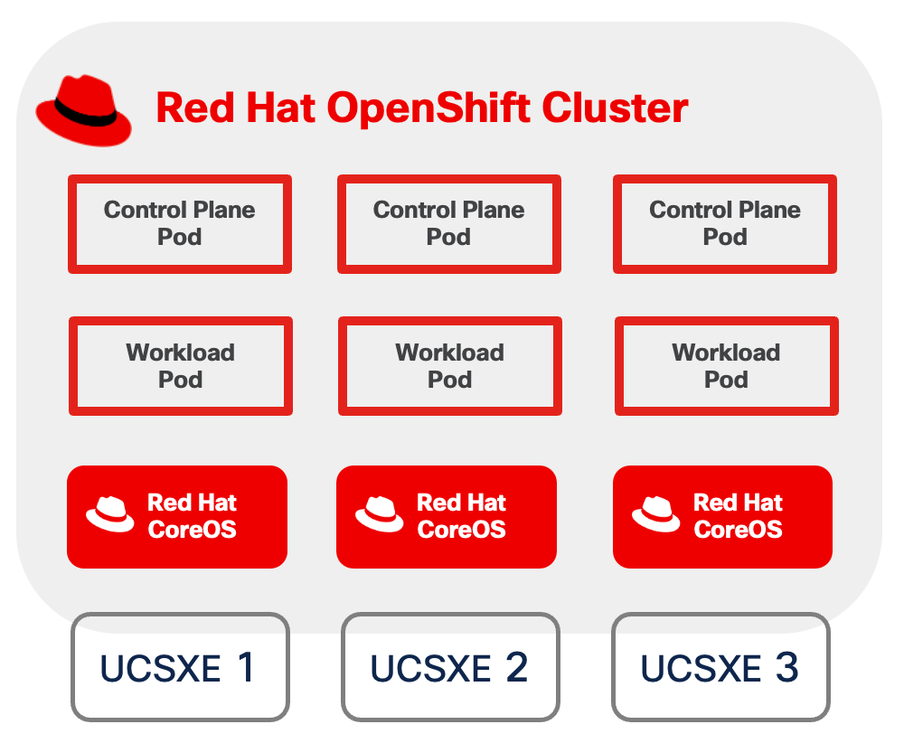
OpenShift Virtualization
OpenShift Virtualization is a feature of Red Hat OpenShift Container Platform that enables you to run and manage virtual machines (VMs) alongside containerized applications within the same Kubernetes-based infrastructure. Built on the open-source KubeVirt technology, OpenShift Virtualization extends the capabilities of OpenShift to support traditional virtualized workloads.
● Creation, configuration, and management of Linux and Windows virtual machines as native Kubernetes resources.
● Multiple access and administration interfaces, including web-based consoles (VNC and serial console), SSH, and remote desktop protocols (RDP for Windows VMs).
● Flexible management of VM resources, including attachment and configuration of multiple network interface controllers (NICs). Storage can be provisioned from Kubernetes persistent volumes, enabling integration with enterprise storage solutions and cloud-native storage providers.
● Live migration of virtual machines between OpenShift nodes with zero downtime.
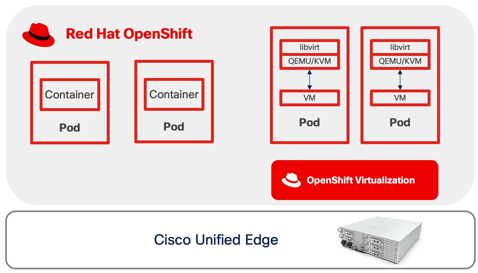
For more information about OpenShift Virtualization, see: https://www.redhat.com/en/technologies/cloud-computing/openshift/virtualization
OpenShift Data Foundation
Red Hat OpenShift Data Foundation (ODF) delivers software-defined storage capabilities and provisions storage services through the following components accessible using Kubernetes storage classes:
● Block Storage (RBD - RADOS Block Device): Provides high-performance block storage devices optimized stateful applications requiring persistent volumes. Common use cases include:
◦ Virtual machines use RBD-backed PVCs for operating system disks. Additional block storage volumes for databases, application data, and user files.
◦ VM Live Migration support with ReadWriteMany (RWX) access mode.
● Shared File System (CephFS): Delivers a distributed, POSIX-compliant file system with ReadWriteMany (RWX) access mode, enabling multiple pods to simultaneously read and write to shared storage. Typical workloads include:
◦ Red Hat OpenShift internal image registry for container image storage.
● Object Storage Service (RGW - RADOS Gateway): Offers a S3-compatible object storage endpoint that scales to tens of petabytes and billions of objects. Designed for data-intensive applications including:
◦ Machine learning and AI workloads (TensorFlow, PyTorch model storage and datasets)
◦ Storage for structured, semi-structured, and unstructured data formats
◦ Training dataset repositories for edge fine-tuning and continuous learning scenarios
● Multicloud Object Gateway (MCG): Provides a lightweight S3-compatible API endpoint that abstracts data storage and retrieval across multiple cloud object stores. This component enables:
◦ Uploading fine-tuning datasets collected at edge locations for centralized model improvement
◦ Backup and disaster recovery for critical inference configurations and custom models
ODF provides flexibility in storage architecture through two deployment approaches: Internal and External.
● Internal deployment: ODF deploys and manages a dedicated Red Hat Ceph Storage cluster within the OpenShift environment, with storage services co-located on nodes that also run compute and application workloads.
● External deployment: ODF connects to an existing, independently managed Red Hat Ceph Storage cluster deployed outside the OpenShift environment.
This validated design and all subsequent sections are based on the internal deployment model with local disks.
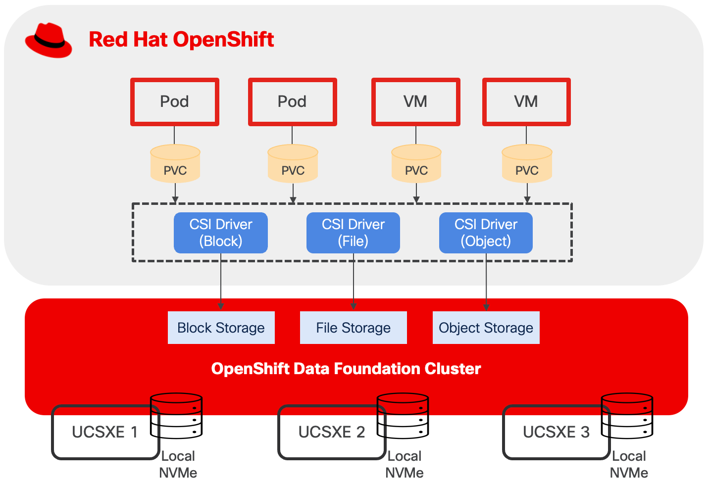
Design Consideration
When performing a sizing exercise to determine the appropriate hardware configuration for Cisco Unified Computing System (Cisco UCS) servers, it is essential to adopt a multi-layered approach. Simply calculating raw compute requirements without considering the nuances of each architectural layer can lead to either performance bottlenecks or wasted resources.
At the application layer, understanding whether applications are stateful or stateless fundamentally impacts sizing decisions.
● Stateless applications, such as web servers, which do not retain session information between requests, typically offer greater flexibility in horizontal scaling and can tolerate more aggressive resource sharing.
● Stateful applications, such as databases, present significantly different requirements. These stateful workloads generally require at least three instances to ensure high availability and quorum-based consensus. Additionally, stateful applications often demand high I/O performance and high network throughput to manage persistent data operations, transaction processing, and replication traffic.
◦ When high IOPS capabilities is needed, IO-optimized UCSXE servers should be considered.
◦ Dedicated network for data replications should be considered in the design to prevent resource contention that could degrade application performance.
Sizing
CPU and Memory
When running OpenShift compact cluster, the minimal resource requirements for each node are listed below:
● 8 CPU cores
● 16 GB RAM
● 120GB disk space
When deploying containers and virtual machines on top of OpenShift, sizing must also account for multiple factors, which include, but not limited to:
● Overhead of OpenShift Virtualization
● CPU and memory for VM workloads, including oversubscriptions
● CPU and memory request/limits for containerized workload
● Special resources may be allocated to VM such as dedicated CPUs, GPU, and so on.
For more information, see the OpenShift Virtualization Cluster Sizing Guide.
OpenShift Data Foundation introduces a layer of overhead in terms of CPU, memory, and storage devices. This overhead is essential for providing persistent, highly available, and scalable storage for containerized and virtualized applications.
Red Hat OpenShift Data Foundation offers three performance profiles that can be selected during or after deployment, based on available resources and desired performance levels.
● The lean profile minimizes resource consumption but may sacrifice some performance capabilities.
● The balanced profile, serving as the default configuration, provides a middle ground between resource efficiency and performance optimization, appropriate for most general-purpose production workloads.
● The performance profile, conversely, allocates additional CPU and memory resources to the storage layer to maximize throughput and minimize latency, making it ideal for I/O-intensive applications but requiring more substantial hardware resources.
Table 9. ODF Performance Profile and Resource Requirements
| Performance Profile |
vCPU |
Memory |
Minimal Storage Devices |
Addition Device Set |
| Lean |
24 |
72GiB |
3 |
6 vCPU 15GiB memory 3 Storage Devices |
| Balanced (Default) |
30 |
72GiB |
3 |
|
| Performance |
45 |
96GiB |
3 |
Storage
This design separates operating system functions from container workloads using dedicated physical storage devices:
● M.2 SSD drive with RAID 1, is used for several important functions beyond installing RHCOS. This includes runtime storage for OS and platform features (images, log data, etc.), ephemeral volumes, etcd storage for control plane nodes, kubelet data, and more.
● NVMe drives are exclusively for OpenShift Data Foundation. ODF consumes the entire NVMe capacity to provision block, file, and object storage services for both containerized and virtualized applications.
This storage design follows Cisco best practices for converged infrastructure deployments, providing both operational reliability through RAID protection and optimal performance through dedicated NVMe allocation for persistent storage workloads.
ODF distributes data across failure domains to ensure data availability and protection against hardware failures. Failure domains are logical groupings that can be defined at the host, rack, or zone level, to ensure data availability and protection against hardware failures. By default, ODF employs a replication factor of 3, which creates three complete copies of data. Each replica is placed in a separate failure domain.
In a 3-node ODF cluster where each node contains a single 1.9 TB disk, the total raw capacity is 5.7 TB (3 nodes × 1.9 TB). However, with replication factor 3, the usable capacity is approximately 1.7 TB considering Ceph metadata overhead and reserved space for cluster operations. In additional, plan storage capacity with 20-30 percent overhead to avoid performance issues as the cluster fills.
● 1.7 TB with 30% overhead: 1.7 TB × 0.70 = 1.19 TB usable
● 1.7 TB with 20% overhead: 1.7 TB × 0.80 = 1.36 TB usable
If a single set of 1.9 TB disks per node does not provide sufficient capacity for the workload requirements, add disks in multiples of three and distribute disks evenly by adding an equal number of disks to each node across all failure domains. New disks must match the size of existing disks already deployed in the cluster.
For example, if a total of six disks is required, install two disks on each node across the three failure domains (2 disks × 3 nodes = 6 disks total). This ensures all disks are utilized and data remains balanced. If the number of disks is not a multiple of three, for example, five disks, ODF will only provision and use three of those disks (the largest complete multiple).
Be aware that, for each additional device set, such as 3 storage devices in the case of OpenShift compact cluster, more CPU and memory are required:
● 6 vCPU
● 15GiB memory
For more information, see the Red Hat OpenShift Data Foundation documents.
Network
VLAN Usage
Table 10. OpenShift Compact Cluster VLAN Example
| VLAN ID |
Name |
Usage |
| 1315 |
OOB-MGMT-VLAN |
Out-of-band management VLAN to connect management ports for various devices. |
| 1316 |
IB-MGMT-VLAN |
In-band management VLAN utilized for all in-band management connectivity. Native VLAN. |
| 1317 |
ACCESS-VLAN |
Access for OpenShift hosts |
| 1318 |
WORKLOAD-VLAN |
Dedi Dedicated VLAN for VM secondary network |
| 1319 |
LIVE-MIGRATION-VLAN |
Traffic for VM live migration between OpenShift nodes |
| 1320 |
STORAGE-VLAN |
Storage replication traffic VLAN for OpenShift Data Foundation |
Some of the key highlights of VLAN usage are as follows:
● VLAN 1315 allows you to manage and access out-of-band management interfaces of various devices and is brought into the infrastructure to allow IMC access to the Unified Edge ECMC or Catalyst devices. Interfaces in this VLAN are configured with MTU 1500.
● VLAN 1316 served as in-band management VLAN which is required to use vMedia policy and CIMC-Mounted ISO images inside Unified Edge. Interfaces in this VLAN are configured with MTU 1500.
● VLAN 1317 is used to access OpenShift hosts. Interfaces in this VLAN are configured with MTU 1500.
● VLAN 1318 is added to provides an additional interface that connects virtual machines to dedicated or isolated network. Interfaces in this VLAN are configured with MTU 1500.
● VLAN 1319 is used to perform live migration of VMs between OpenShift nodes. Interfaces in this VLAN are configured with MTU 9000.
● VLAN 1320 is configured to allow storage replication traffic between ODF nodes. Interfaces in these VLANs are configured with MTU 9000.
At least one VLAN-ID must be specified inside Cisco Unified Edge and mapped as Native-VLAN to allow network traffic to the next-hop switch without VLAN tagging.
OpenShift Cluster and Service Networks
During OpenShift installation, two primary internal IP subnets must be configured:
● Cluster network CIDR (also called the Pod network), default to 10.128.0.0/14, provides IP addresses to pods and VMs running in the cluster. OpenShift allocates each pod a cluster IP address for Pod-to-Pod communication. With OpenShift Virtualization, VMs are also deployed as pods and receive their own cluster IP addresses.
● Service network CIDR, defaults to 172.30.0.0/16, allocates virtual IP addresses to Services for stable endpoint access.
The Cluster network and Service network must not overlap with each other. The Cluster network IP range should not overlap with other IP space external to the cluster, which VMs or Pods may need to connect to. This includes the subnet where OCP nodes reside. For example, if three OCP nodes are configured with IP address in the subnet 10.131.6.0/24, then Cluster network must be changed from the default CIDR, which is 10.128.0.0/14, to another one, such as 10.120.0.0/14.
OpenShift Virtualization Related Network - VM Secondary Network
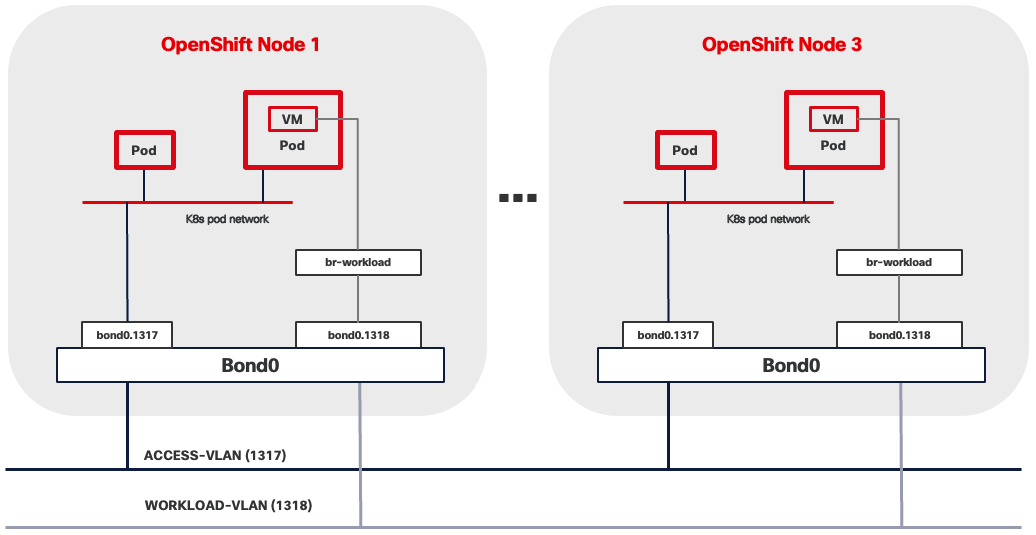
VM Secondary Networks in OpenShift Virtualization provide additional network interfaces beyond the default pod network, enabling virtual machines to connect directly to external Layer 2 or Layer 3 networks. This capability leverages Multus CNI (Container Network Interface) to attach VMs to multiple networks simultaneously while maintaining the pod network for Kubernetes cluster communication.
When using this architecture, consider the following network implications:
● VLAN reserved for VM secondary network must be present across the entire data path across the network infrastructure. This includes:
◦ BOND interface, such as bond0.1318, shown in Figure 28.
◦ Network segment between UCSXE servers and ECMCs.
◦ Network segment between ECMCs and upstream switches if Layer 2 connectivity between VMs and external network services is desired.
◦ All network segments from ECMCs to edge platforms if Layer 3 routing is required.
● Spanning Tree Protocol (STP) must be disabled if Linux Bridge or OVS (Open Virtual Switch) are used to connect VM secondary network to underlying infrastructure.
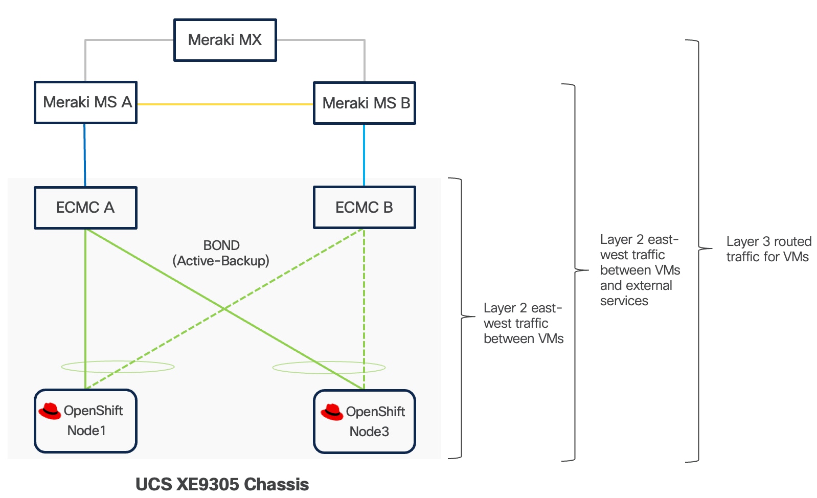
Live Migration
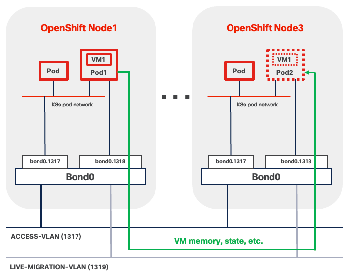
OpenShift Virtualization supports live migration of virtual machines between cluster nodes. The migration process transfers the complete VM state, including memory contents and storage references, while maintaining active network connections and minimizing service interruption.
In OpenShift compact clusters, Multus is commonly used with various CNI plugins to create a dedicated networks for VM live migration traffic between the three nodes. The Live migration network operates as a Layer 2 network segment, eliminating the need for routing capabilities or gateway configuration.
When using this architecture, consider the following network implications:
● VLAN reserved for Live Migration Network must be present on ALL three nodes and along the data path, including:
◦ VLAN subinterface, such as bond0.1319, shown in Figure 30.
◦ Network segments between UCSXE servers and ECMCs.
● MTU must be set to 9000 end-to-end, including:
◦ VLAN subinterface, such as bond0.1319, shown in Figure 30.
◦ Bond interface, such as bond0, shown in Figure 30.
◦ All physical host ports in CoreOS participating in the bond interface
◦ Embedded switches inside ECMCs. This is a global switch-level setting that applies to all VLANs and cannot be configured on a per-VLAN basis.
● Spanning Tree Protocol (STP) must be disabled if Linux Bridge or OVS (Open Virtual Switch) are used to connect Live Migration network to underlying infrastructure.
OpenShift Data Foundation Network - Minimum Bandwidth Requirements
For production deployments of a three-node ODF cluster on OpenShift compact cluster, a minimum of 10 Gbps network bandwidth is required, 25 Gbps recommended for performance between all nodes. When deploying ODF on Cisco UCS XE130c M8 servers, Cisco UCS XE130c M8 servers connected through the same eECMC benefit from 25 Gbps of available bandwidth between nodes, which comfortably satisfies the requirement for ODF deployments.
OpenShift Data Foundation Network - Network Separation in ODF
One of the most important design decisions with ODF deployment on OpenShift compact cluster is the separation of two different types of traffic.
● ODF client traffic uses the standard Kubernetes pod network shared by all pods and virtual machines.
● ODF data replication traffic that maintains data redundancy across the three nodes, is isolated on a dedicated Layer 2 network segment.
This separation means that read/write transactions from a client application will not slow down the background replication that maintains data protection, and conversely, intensive rebalancing operations will not degrade the performance experienced by end users.
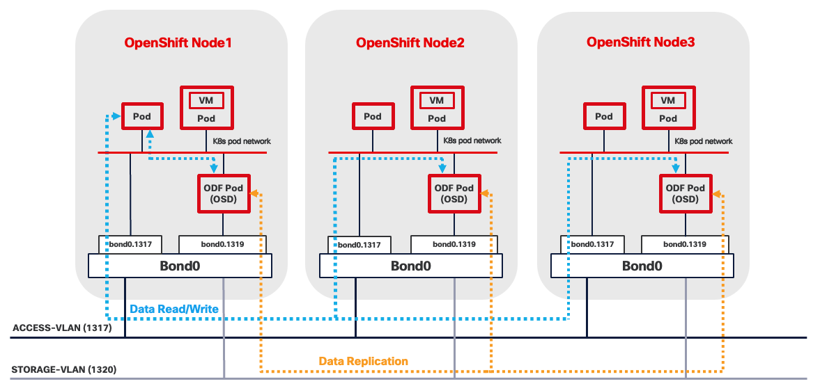
The ODF cluster network operates as a Layer 2 network segment, eliminating the need for routing capabilities or gateway configuration.
When using this architecture, consider the following network implications:
● VLAN reserved for ODF cluster network must be present on ALL three nodes and along the data path. This includes:
◦ VLAN subinterface, such as bond0.1320, shown in Figure 31.
◦ Network segments between UCSXE servers and ECMCs.
● MTU must be set to 9000 end-to-end, including:
◦ VLAN subinterface, such as bond0.1320, shown in Figure 31.
◦ Bond interface, such as bond0, shown in Figure 31.
◦ All physical host ports in CoreOS participating in the bond interface.
◦ Embedded switches inside ECMC. This is a global switch-level setting that applies to all VLANs and cannot be configured on a per-VLAN basis.
● Spanning Tree Protocol (STP) must be disabled if Linux Bridge or OVS (Open Virtual Switch) are used to connect ODF cluster network to underlying infrastructure.
Red Hat AI Inference Server
Deploying inferencing servers at edge locations enables organizations to process AI workloads locally, eliminating the latency, bandwidth costs, and connectivity dependencies associated with cloud-based inference. Edge inferencing with Red Hat AI Inference Server on compact infrastructure like Cisco Unified Edge with NVIDIA L4 GPU provides the computational power necessary for these demanding workloads at edge locations.
The Red Hat AI Inference Server is an enterprise-grade, fully supported product designed for container-based deployment across Red Hat Enterprise Linux and OpenShift environments. It leverages the vLLM open-source inference server for large language models (LLM). The vLLM runtime delivers the following validated capabilities:
● High-Throughput Serving: Optimized request scheduling and memory management for generative AI workloads
● Extended Context Windows: Support for large input sequences up to model-specific context limits
● Multi-GPU Distribution: Model tensor parallelism and pipeline parallelism for accelerated inference
● Continuous Batching: Dynamic request batching to maximize GPU utilization and reduce latency
The inference server integrates LLM Compressor capabilities to enable model optimization techniques that reduce computational requirements. Supported optimization methods include:
● Quantization: INT8 and INT4 weight quantization for reduced memory footprint
● Pruning: Structured and unstructured pruning to eliminate redundant parameters
● Knowledge Distillation: Model compression through teacher-student training approaches
The NVIDIA L4 GPU provides 24GB of GDDR6 memory, which represents the primary constraint for model selection. Model memory requirements include not only the base parameter weights but also Key-Value (KV) cache for managing context during inference, activation memory, and framework overhead. In general, small models (up to 7-8B parameters) can run comfortably using INT4, INT8, or FP8 quantization techniques applied to both weights and activations.
Consider models that have been pre-quantized and validated by Red Hat. The Red Hat AI repository on Hugging Face hosts a collection of models validated for compatibility with the inference server environment.
For the complete list, go to: https://www.redhat.com/en/products/ai/validated-models.
For more information about the Red Hat AI Inference server, see the Red Hat AI Inference Server document for more information about Red Hat AI Inference Server.
Management
OpenShift Web Console
The OpenShift Web Console is a browser-based management interface that provides access to cluster operations and monitoring capabilities. You can access the console through standard web browsers over HTTPS connections, enabling remote management from any location with network connectivity to the cluster. The interface supports common administrative tasks including application deployment, resource scaling, configuration management, and cluster monitoring. The OpenShift Web Console also provides access to virtualization features, allowing administrators to create, start, stop, migrate, and delete virtual machines from any location with network connectivity to the cluster.

OpenShift Command Line Interface (oc)
The OpenShift Command Line Interface (oc) is a powerful tool to manage OpenShift clusters, containers and virtual machines on the OpenShift platform through a unified interface. It includes all kubectl's functionality plus additional commands for OpenShift-specific features. For containers, oc provides comprehensive capabilities including deploying applications, managing pods and deployments, scaling workloads, viewing logs, executing commands inside containers, and managing resources like services, routes, and config maps. With OpenShift Virtualization, the oc tool extends its functionality to manage virtual machines alongside containerized workloads, allowing you to create, start, stop, and delete VMs, manage VM templates, handle storage volumes, and perform live migrations.
Virtctl
The virtctl command-line utility manages virtual machines in the OpenShift Virtualization environment. The tool provides commands for common VM operations including starting, stopping, pausing, and live migrating virtual machines between cluster nodes through the Kubernetes API. Virtctl also supports advanced functionality such as accessing VM serial consoles for troubleshooting and uploading virtual disk images to the cluster for VM provisioning.
Infrastructure Service
DNS
The Domain Name System (DNS) serves as a foundational component for OCP Platform operations and is critical for maintaining cluster availability. The DNS servers may reside on the internet, in a public cloud, at an edge data center, or at a headquarters location. Ensure that all OpenShift nodes always maintain continuous network connectivity to the DNS servers.
Configure DNS zones to support both forward (name-to-IP) and reverse (IP-to-name) lookups for a defined set of DNS entries as listed in Table 11.
Table 11. OpenShift Compact Cluster DNS Entries
| Components |
Required Records |
Record Type |
Description |
| OpenShift API (External) |
api.<cluster_name>.<base_domain> |
A/AAAA, CNAME, and PTR |
Resolvable by external clients and all cluster nodes. |
| OpenShift API (Internal) |
api-int.<cluster_name>.<base_domain> |
A/AAAA, CNAME, and PTR |
Resolvable by all cluster nodes. |
| Application Routes |
*.apps.<cluster_name>.<base_domain> |
A/AAAA, CNAME, and PTR |
It ensures that applications are accessible both externally and from within the cluster. |
| OpenShift Nodes |
<node-name>.<cluster_name>.<base_domain> |
A/AAAA, CNAME, and PTR |
Identifies each worker/compute machine |
DHCP
To maintain predictability and avoid IP conflicts, it is recommended to use DHCP reservations.
NTP
For many reasons, including authentication and log correlation, it is critical that all unified edge components are properly synchronized to multiple, redundant NTP time sources.
Load Balancer
OpenShift supports both internal and external load balancer configurations. It's common to use a built-in VIP-based internal load balancer. It removes the need for additional external load balancer infrastructure. If containerized or virtualized applications requires heavy use of the OpenShift Route/ingress capabilities, external load balancers must be provided.
Remote Access
For external access to OpenShift management interfaces and deployed applications, ensure the following TCP ports are accessible:
● OpenShift API Server (TCP 6443) is required for, OpenShift web console, oc and virtctl operations.
● Ingress Controller Access (TCP Ports 443 and 80) provides external access to the OpenShift web console user interface, deployed HTTP and HTTPS applications exposed through OpenShift Routes.
● Service-Specific Access for non-HTTP applications requires configuration of OpenShift Services with type LoadBalancer or NodePort. LoadBalancer services provision external load balancer resources that expose applications on specific TCP or UDP ports with dedicated IP addresses. NodePort services expose applications on high-numbered ports across all cluster nodes.
Software Components
Table 12 lists various software components used in the solution.
Table 12. Software components and versions
|
|
Component |
Validated version |
| Network |
Meraki MX68W |
MX 18.211.6 |
| Meraki MS (C9300L-24UXG-4X) |
CS 17.2.2 |
|
| Compute |
UCSXE-9305 |
Infrastructure Bundle 6.0(1.251005) |
| UCSXE-130C-M8 |
Server Bundle 6.0(1.251026) |
|
| Storage |
Red Hat OpenShift Data Foundation |
4.19.6 |
| Orchestration |
Red Hat OpenShift |
4.19.13 |
| Red Hat OpenShift Virtualization |
4.19.12 |
|
| AI Inference |
Red Hat AI Inference Server |
3.2.2 |
| NVIDIA GPU Operator |
25.10.0 |
About the authors
Shixiong Shang, Technical Marketing Engineer, UCS Solutions, Cisco Systems, Inc.
Shixiong Shang has over 25 years of experience in routing, switching, and enterprise applications. He specializes in infrastructure automation, virtualization, OpenShift/Kubernetes, and cloud computing. Shixiong is passionate about open-source technologies and has deep expertise in operations and observability.
Jonathan Wong, Solutions Architect, Red Hat
Jonathan has over 20-years of experience in the industry specializing in OpenShift/Kubernetes, Virtualization, AI, and Cloud Computing.
Acknowledgements
For their support and contribution to the design, validation, and creation of this Cisco Validated Design, the authors would like to thank:
● Chris O’Brien, Director, UCS Solutions, Cisco Systems, Inc.
● Ulrich Kleidon, Principal Engineer, UCS Solutions, Cisco Systems, Inc.
● Michael Hrivnak, Distinguished Engineer, RHCE, Red Hat
Feedback
For comments and suggestions about this guide and related guides, join the discussion on Cisco Community here: https://cs.co/en-cvds.
CVD Program
"DESIGNS") IN THIS MANUAL ARE PRESENTED "AS IS," WITH ALL FAULTS. CISCO AND ITS SUPPLIERS DISCLAIM ALL WARRANTIES, INCLUDING, WITHOUT LIMITATION, THE WARRANTY OF MERCHANTABILITY, FITNESS FOR A PARTICULAR PURPOSE AND NONINFRINGEMENT OR ARISING FROM A COURSE OF DEALING, USAGE, OR TRADE PRACTICE. IN NO EVENT SHALL CISCO OR ITS SUPPLIERS BE LIABLE FOR ANY INDIRECT, SPECIAL, CONSEQUENTIAL, OR INCIDENTAL DAMAGES, INCLUDING, WITHOUT LIMITATION, LOST PROFITS OR LOSS OR DAMAGE TO DATA ARISING OUT OF THE USE OR INABILITY TO USE THE DESIGNS, EVEN IF CISCO OR ITS SUPPLIERS HAVE BEEN ADVISED OF THE POSSIBILITY OF SUCH DAMAGES.
THE DESIGNS ARE SUBJECT TO CHANGE WITHOUT NOTICE. USERS ARE SOLELY RESPONSIBLE FOR THEIR APPLICATION OF THE DESIGNS. THE DESIGNS DO NOT CONSTITUTE THE TECHNICAL OR OTHER PROFESSIONAL ADVICE OF CISCO, ITS SUPPLIERS OR PARTNERS. USERS SHOULD CONSULT THEIR OWN TECHNICAL ADVISORS BEFORE IMPLEMENTING THE DESIGNS. RESULTS MAY VARY DEPENDING ON FACTORS NOT TESTED BY CISCO.
CCDE, CCENT, Cisco Eos, Cisco Lumin, Cisco Nexus, Cisco StadiumVision, Cisco TelePresence, Cisco WebEx, the Cisco logo, DCE, and Welcome to the Human Network are trademarks; Changing the Way We Work, Live, Play, and Learn and Cisco Store are service marks; and Access Registrar, Aironet, AsyncOS, Bringing the Meeting To You, Catalyst, CCDA, CCDP, CCIE, CCIP, CCNA, CCNP, CCSP, CCVP, Cisco, the Cisco Certified Internetwork Expert logo, Cisco IOS, Cisco Press, Cisco Systems, Cisco Systems Capital, the Cisco Systems logo, Cisco Unified Computing System (Cisco UCS), Cisco UCS B-Series Blade Servers, Cisco UCS C-Series Rack Servers, Cisco UCS S-Series Storage Servers, Cisco UCS X-Series, Cisco UCS Manager, Cisco UCS Management Software, Cisco Unified Fabric, Cisco Application Centric Infrastructure, Cisco Nexus 9000 Series, Cisco Nexus 7000 Series. Cisco Prime Data Center Network Manager, Cisco NX-OS Software, Cisco MDS Series, Cisco Unity, Collaboration Without Limitation, EtherFast, EtherSwitch, Event Center, Fast Step, Follow Me Browsing, FormShare, GigaDrive, HomeLink, Internet Quotient, IOS, iPhone, iQuick Study, LightStream, Linksys, MediaTone, MeetingPlace, MeetingPlace Chime Sound, MGX, Networkers, Networking Academy, Network Registrar, PCNow, PIX, PowerPanels, ProConnect, ScriptShare, SenderBase, SMARTnet, Spectrum Expert, StackWise, The Fastest Way to Increase Your Internet Quotient, TransPath, WebEx, and the WebEx logo are registered trade-marks of Cisco Systems, Inc. and/or its affiliates in the United States and certain other countries. (LDW_P2)
All other trademarks mentioned in this document or website are the property of their respective owners. The use of the word partner does not imply a partnership relationship between Cisco and any other company. (0809R)