Cisco Unified Edge and Canonical Ubuntu LXD, MicroCloud and Kubernetes Deployment Guide
Available Languages
Bias-Free Language
The documentation set for this product strives to use bias-free language. For the purposes of this documentation set, bias-free is defined as language that does not imply discrimination based on age, disability, gender, racial identity, ethnic identity, sexual orientation, socioeconomic status, and intersectionality. Exceptions may be present in the documentation due to language that is hardcoded in the user interfaces of the product software, language used based on RFP documentation, or language that is used by a referenced third-party product. Learn more about how Cisco is using Inclusive Language.
- US/Canada 800-553-2447
- Worldwide Support Phone Numbers
- All Tools
 Feedback
 Feedback

In partnership with:
![]()
About the Cisco Validated Design Program
The Cisco Validated Design (CVD) program consists of systems and solutions designed, tested, and documented to facilitate faster, more reliable, and more predictable customer deployments. For more information, go to: http://www.cisco.com/go/designzone.
Executive Summary
We’re at a critical inflection point. The edge has emerged as the place where the physical and digital worlds meet, demanding real-time processing and analysis of data to deliver informed decisions, improved experiences, and increased productivity. However, legacy infrastructure wasn’t built for the AI era and can’t keep up with the scale, speed, and intelligence required by AI-driven operations. While much of the model training happens in the data center, the shift of test-time inference to the edge makes it the new frontier for enterprise AI.
Deploying AI at the edge remains complicated and demanding. Interoperability, security, cost, and rigid deployment models are all potential performance and productivity blockers. The increasing demand for AI and digitization at the edge necessitates a full system rethink, as evolving business needs and the sheer scale highly distributed edge environments and modern AI workloads create a beyond-human complexity nightmare. We need something more than just more boxes; we need a brand-new edge infrastructure and operations vision.
Cisco Unified Edge is an AI-ready system that redefines computing at the edge by converging compute, networking, storage, and security. Designed from the edge up, for the next decade, the modular design is future-ready, energy-efficient, and easy-to-service, and can be tailored to support today’s workloads and use cases, while remaining adaptable to the rapidly evolving AI landscape. Seamless integration with third-party technologies and validated solutions for industry-specific needs ensure both compatibility and optimized performance.
Delivering breakthrough operational simplicity at scale, this software-defined system features centralized cloud management, zero-touch deployment, curated blueprints, and automated orchestration. These capabilities enable high scalability with minimal complexity. End-to-end observability with real-time analytics accelerates error detection and correction, helping minimize service outages. Security is designed-in, with integrated physical and digital safeguards to protect applications and data at the edge while multi-layered security capabilities protect infrastructure, applications, and AI models.
By combining compute, networking, security, and storage into a full stack, AI-ready system, Cisco Unified Edge introduces a fundamentally different infrastructure and operational paradigm for the enterprise edge. Unlike other solutions that may lack critical capabilities or are not optimized for edge use cases, this system offers fully validated solutions that deliver AI-era performance, simplicity, and security.
Benefits
Key benefits are:
● Future-ready performance: Adaptable to meet today and tomorrow's edge workload demands with ease, stopping the rip-and-replace cycle with a fully integrated, modular edge environment built for the next decade. Deploy applications and infrastructure faster and profit sooner with proven solutions that are tested and certified for vertical-specific workloads and use cases, ensuring compatibility and performance.
● Full-scale simplicity: Onboard quickly and with ease without the need for highly skilled IT expertise or on-site visits. Whether deploying ten systems or ten thousand, zero-touch provisioning, curated blueprints and automation ensure consistent, effortless rollout. A consistent operating model from core to edge makes it easy to scale, upgrade, and support your infrastructure.
● Designed-in security: Prevent tampering at the edge with robust physical and digital protection. Proven policy-based templates eliminate configuration drift across sites. Embedded, zero-trust security capabilities ensure unmatched protection for your edge infrastructure, data, and AI models.
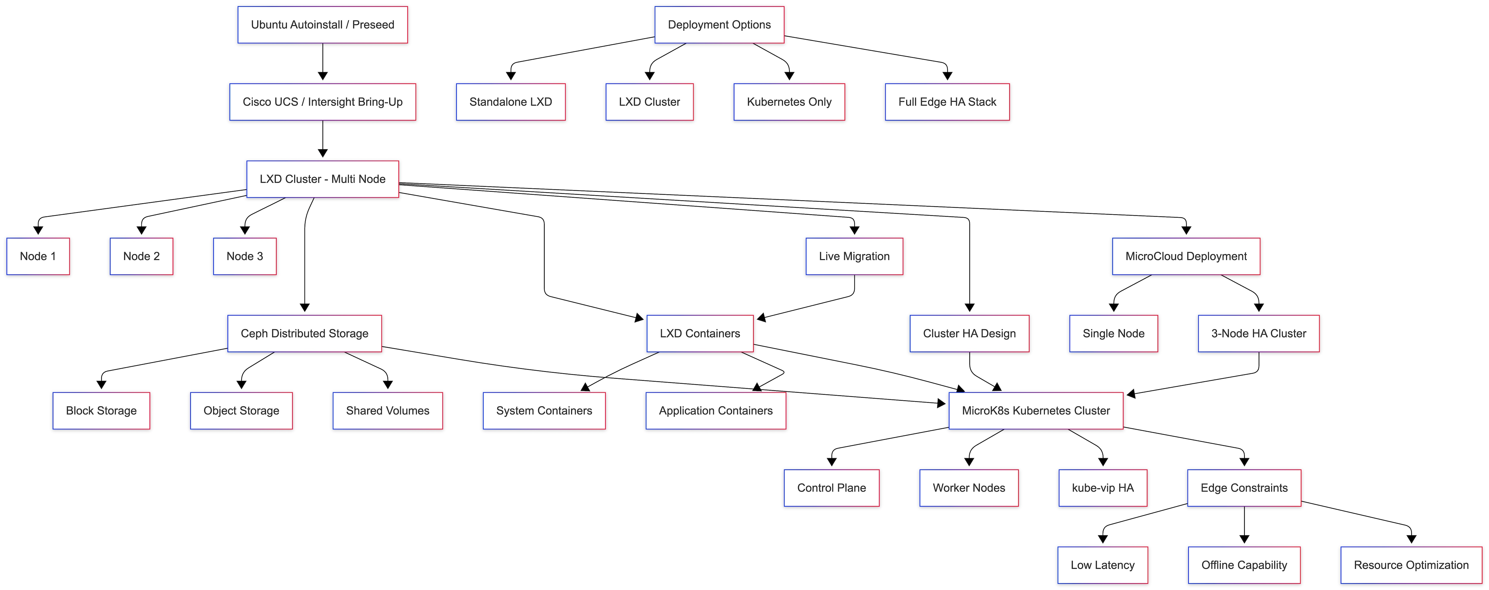
Canonical, the company behind Ubuntu, offers a robust and composable suite of open-source technologies designed to streamline enterprise IT operations, accelerate innovation, and reduce complexity across cloud, datacenter, and edge environments. This technical design guide explores how Canonical’s portfolio can be effectively used on Cisco Unified Edge System (Cisco UCS XE9305) to deliver scalable, secure, and cost-efficient solutions.
Canonical’s modular architecture aligns with Cisco Unified Edge infrastructure model, enabling:
● Rapid provisioning and scaling of workloads
● Unified management across compute, storage, and networking
● Optimized performance for cloud-native and legacy applications
Together, Canonical and Cisco Unified Edge empower enterprises to build resilient, future-ready platforms that support digital transformation, edge computing, and AI innovation.
The design of this solution is driven by its ability to evolve and incorporate both technology and product innovations in the areas of management, computing, storage, and networking to be used at the Edge. To help organizations with their digital transformation and application modernization practices, Cisco and Canonical have partnered to produce this Cisco Validated Design (CVD) for the joint Unified Edge and Canonical solution minimizing risks by validating the integrated architecture to ensure compatibility between various components. The solution also addresses pain points by providing documented design guidance, deployment guidance, and support that can be used in various stages (planning, designing, and implementation) of a business project targeting Edge deployments. The solution is part of Cisco’s Blueprint and Fleet management enhancement of Intersight and will be delivered as IaC to further eliminate error-prone manual tasks, allowing quicker and more consistent solution deployments.
Introduction
This chapter contains the following:
● Audience
This Cisco Validated Design (CVD) describes a validated edge architecture that combines Cisco Unified Edge infrastructure with Canonical software to support bare-metal, virtualized, and containerized workloads in distributed environments. The design is intended for customers who need a repeatable and operationally efficient platform that can be deployed at remote sites, managed centrally, and scaled from a single node to a small multi-node cluster.
Unlike a general product overview, this section focuses only on the architectural elements that matter to the validated design. The goal is to establish the infrastructure context for the deployment models covered later in the document, specifically single-node Ubuntu with LXD, mixed LXD and Canonical Kubernetes deployments, and multi-node clustered edge designs based on Canonical MicroCloud.
At the edge, infrastructure decisions are often shaped by practical constraints rather than raw scale alone. Space, power, cooling, limited on-site IT presence, and the need for consistent remote operations all influence platform selection. For that reason, this CVD emphasizes a compact but capable infrastructure model that supports operational consistency, workload flexibility, and lifecycle automation through Cisco Intersight.
The intended audience of this document includes but is not limited to IT architects, sales engineers, field consultants, professional services, IT managers, partner engineering, and customers who want to take advantage of an infrastructure built to deliver efficiency and enable innovation. The expected reader is not looking for deep standalone product documentation. Instead, the intended audience needs design-level guidance on how the Cisco and Canonical components fit together as a validated platform.
The purpose of this guide is to provide design guidance for deploying Canonical software on Cisco Unified Edge using Cisco Intersight as the primary management and automation framework. It identifies the relevant platform components, explains how they contribute to the validated architecture, and highlights the workload patterns most applicable to edge environments.
This document does not define a complete AI application architecture. It defines the validated infrastructure and software foundation on which AI and analytics applications can be deployed. That distinction is important because it keeps the guide broadly useful across industries while still addressing the infrastructure requirements common to AI-enabled edge deployments.
This document does not attempt to reproduce full hardware data sheets or complete product manuals. Where deeper platform detail is required, the reader should refer to the published Cisco design guide and associated product documentation. Instead, this section focuses on the subset of information necessary to understand the design intent and justify the technology choices used in this document.
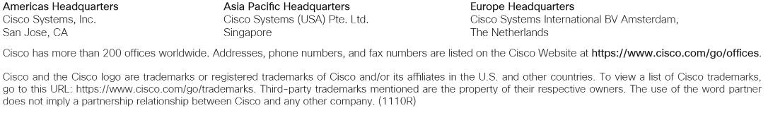
Cisco Unified Edge with Canonical provides an integrated platform for running Linux-based edge workloads across several operational models. The validated stack combines Cisco compute and connectivity, Intersight-based lifecycle management, Ubuntu Server as the host operating system, and Canonical tooling for containers, virtual machines, Kubernetes, and clustered edge cloud services.
From a design perspective, the solution offers several key benefits:
● a consistent deployment model across multiple edge locations
● support for both traditional and cloud-native workloads
● modular scaling from single-node systems to resilient clusters
● centralized policy-driven operations through Cisco Intersight
● readiness for AI inferencing and accelerated analytics workloads
The validated deployment patterns in this document can be summarized as follows:
● Single-node Ubuntu Server with LXD
A compact and efficient model for running Linux services, system containers, and virtual machines on a single edge node.
● Single-node Ubuntu Server with LXD and Canonical Kubernetes
A mixed workload model that supports system containers or virtual machines alongside Kubernetes-managed application containers on the same host.
● Multi-node Canonical MicroCloud
A scale-out design that introduces clustering, distributed services, and improved resilience for workloads that outgrow a single-node footprint.
These deployment options allow you to choose an architecture that matches site-specific requirements without abandoning a common operational model. You can scale-up by adding more resources to the solution or scale-out by adding more Unified Edge instances.
Technology Overview
This chapter contains the following:
● Why This Stack Fits AI/ML Edge Workloads
The validated solution is built on the following core elements:
Cisco Unified Edge Management
Cisco Unified Edge is part of the Cisco UCS portfolio, but it is tailored for environments where a traditional data center deployment model is not ideal. In this design, the management plane is centered on Cisco Intersight, which provides the control point for policy definition, automation, hardware lifecycle tasks, and repeatable deployment at scale.
This is especially important in edge use cases, where remote locations may not have dedicated IT staff and where operational consistency is often more important than site-specific customization. Intersight makes it possible to apply a uniform configuration model across multiple edge systems and reduce the risk of manual drift.
Cisco Intersight
Cisco Intersight is the infrastructure lifecycle management and automation platform used in this document. Within the context of this solution, its primary role is to simplify the deployment and ongoing management of Cisco Unified Edge systems.
The capabilities most relevant to this guide include:
● centralized inventory and health visibility
● policy-based server configuration
● automation through APIs, templates, and blueprints
● simplified deployment of consistent configurations across many sites
● lifecycle management aligned with a repeatable operational model
For customers with additional security or data locality requirements, Cisco also provides on-premises deployment models for Intersight. That detail is secondary to the validated design itself, but it is useful to note that the same operational principles can be preserved across different management deployment models.
Cisco Unified Edge System
The Cisco Unified Edge platform provides the physical infrastructure foundation for the solution. It is designed for locations that need enterprise-grade compute and connectivity but cannot assume the conditions of a full data center. As a result, the platform balances compact form factor, performance, flexibility, and operational simplicity.
For this document, the most relevant platform characteristics are:
● support for compact, edge-optimized compute
● local operating system and workload storage
● integrated management through the edge chassis domain
● support for redundant connectivity patterns
● support for GPU acceleration where required
● suitability for both standalone and clustered deployment models
The purpose of this section is not to restate complete hardware specifications. Instead, it establishes why the platform is appropriate for the validated Canonical software stack and the deployment models discussed later in the guide.
NVIDIA L4 GPU
When AI inferencing, video analytics, or accelerated data processing is required, the solution can incorporate the NVIDIA L4 Tensor Core GPU. The L4 is particularly relevant to edge environments because it combines strong inferencing performance with a power-efficient and compact form factor.
Within this document, GPU acceleration is relevant for workloads such as:
● computer vision
● video stream analysis
● anomaly detection
● accelerated AI inferencing
● data processing pipelines that benefit from parallel execution
The presence of GPU support does not change the architectural model of the guide, but it expands the range of workloads that the platform can host efficiently.
Canonical Software Stack
Ubuntu Server
Ubuntu Server is the host operating system used throughout the validated design. It provides a stable and well-supported Linux foundation with strong support for automation, secure package management, modern networking, and long-term support releases suitable for production edge deployments.
For this document, Ubuntu Server is important not only as the base operating system, but also as the integration layer on which LXD, Canonical Kubernetes, and MicroCloud services are deployed.
Canonical LXD
LXD provides system container and virtual machine management for Linux environments. In this validated design, it is the key component used for lightweight virtualization and workload isolation on Ubuntu Server.
LXD is especially well suited to edge deployments because it allows customers to:
● host Linux workloads with low overhead
● run system containers and virtual machines under a common management model
● use local resources efficiently
● support both traditional application packaging and modern service models
For many single-node edge deployments, LXD is the simplest and most practical way to add workload isolation and application density without introducing the complexity of a larger virtualization platform.
Canonical Kubernetes
Canonical Kubernetes provides upstream-conformant container orchestration for application workloads that benefit from Kubernetes-based deployment and lifecycle management. In this document, it is used where cloud-native application packaging, service portability, or Kubernetes-native operating models are required.
This is particularly useful in edge environments that need to combine:
● modern application delivery methods
● small-footprint infrastructure
● centralized lifecycle management
● repeatable deployment across many locations
Canonical MicroCloud
MicroCloud extends the design from a single-node edge model to a clustered architecture by combining LXD, MicroCeph, and MicroOVN into a lightweight integrated edge cloud stack. In this guide, MicroCloud is the preferred path when the validated design needs to grow beyond a single host and introduce resilience, distributed capacity, or clustered workload hosting.
Its role in this document is architectural rather than theoretical. MicroCloud is how the design transitions from simple standalone edge systems to more resilient multi-node platforms without abandoning the Canonical operating model.
Juju and Ansible
Juju and Ansible can complement the base solution as orchestration and automation tools. They are relevant because customers may use them to extend deployment workflows, integrate application automation, or support operational tasks beyond the initial infrastructure bring-up.
However, they are not the primary focus of the architecture described in this section. The foundation of the validated solution remains Cisco Unified Edge, Cisco Intersight, Ubuntu Server, LXD, Canonical Kubernetes, and MicroCloud.
Together, these components form a flexible edge platform capable of hosting:
● Bare-metal Linux applications
● System containers
● Virtual machines
● Kubernetes-based cloud-native workloads
● GPU-accelerated inferencing services
The value of this solution is not just that it runs Canonical software on Cisco infrastructure. The value is that it presents a validated and repeatable architecture for a class of edge deployments that must support different workload types while remaining manageable at scale.
This document is positioned around a few practical design principles:
● prefer operational consistency over site-specific customization
● use a common platform for Linux, virtualization, and Kubernetes where possible
● keep the single-node model simple and efficient
● introduce clustering only where resilience or scale requires it
● align automation and lifecycle operations with Cisco Intersight
These principles keep the design relevant across multiple industries and workload patterns without making it unnecessarily broad.
AI/ML Use Cases
AI Inferencing at the Edge
AI inferencing at the edge enables data to be processed and acted on close to where it is generated rather than sending everything back to a centralized cloud or data center. This model is valuable where low latency, constrained bandwidth, intermittent connectivity, or data sovereignty requirements make centralized processing less practical.
For this document, the AI focus is on inferencing rather than large-scale model training. The role of the validated infrastructure is to provide a reliable and operationally manageable platform on which inferencing services, analytics pipelines, and adjacent edge applications can run.
Representative Use Cases
The validated stack is broadly applicable to several common edge AI and analytics scenarios:
● Industrial automation and predictive maintenance
Sensor data can be processed locally to detect anomalies, reduce downtime, and support near-real-time operational decisions.
● Retail intelligence and smart store operations
Video analytics and local data processing can improve customer flow analysis, inventory visibility, and store operations without requiring all data to traverse back to a central location.
● Security and surveillance analytics
Local inferencing can support faster threat detection, behavioural analysis, and video-based event recognition with lower latency.
● Healthcare and diagnostic edge processing
Edge-based analytics can support localized review of patient data or imaging workflows while helping reduce data movement and preserving responsiveness.
● Smart agriculture and remote sensing
Distributed systems can analyze camera, drone, or sensor data locally to support time-sensitive decisions in remote locations.
Why This Stack Fits AI/ML Edge Workloads
Cisco Unified Edge with Canonical is well aligned with AI-enabled edge deployments because it combines infrastructure flexibility with an operational model that can support remote and distributed environments. Specifically, the stack offers:
● low-latency local processing on an edge-optimized compute platform
● support for GPU acceleration where inferencing performance requires it
● flexible hosting models for virtual machines, system containers, and Kubernetes workloads
● centralized lifecycle management through Cisco Intersight
● a scalable progression from single-node deployments to clustered edge platforms
This makes the design suitable not only for a specific application, but for a broader class of edge solutions that need to combine infrastructure efficiency, remote manageability, and readiness for AI workloads.
Solution Design and Deployment
This chapter contains the following:
● Ubuntu Autoinstall with Edge-Ready Configuration
● Automated Cisco UCS / Intersight Server Bring-Up
● LXD Deployment Options for Edge Workloads
● Live Workload Migration Across MicroCloud Nodes
● Recommended Edge Architecture: MicroCloud with Canonical Kubernetes
● Kubernetes Deployment on LXD VMs - Canonical Kubernetes for Edge
● Edge Deployment Considerations
● Edge Workload Deployment Scenario - AI / IoT Application on Canonical Kubernetes
● Kubernetes + LXD VM Integration
● Standalone versus MicroCloud Deployment
● Standalone LXD versus MicroCloud versus Kubernetes-Only
● Canonical Kubernetes Installation for Edge Deployments
● Single-Node MicroCloud Deployment
● Multi-Node MicroCloud Deployment - 3-Node HA Cluster
● Multi-Node Kubernetes Cluster Deployment using Canonical Kubernetes
● High-Availability Kubernetes with kube-vip on MicroCloud Edge Cluster
● Deploy Kubernetes on MicroCloud Edge Cluster - 3-Node HA
● High-Availability Kubernetes with kube-vip on MicroCloud Edge Cluster
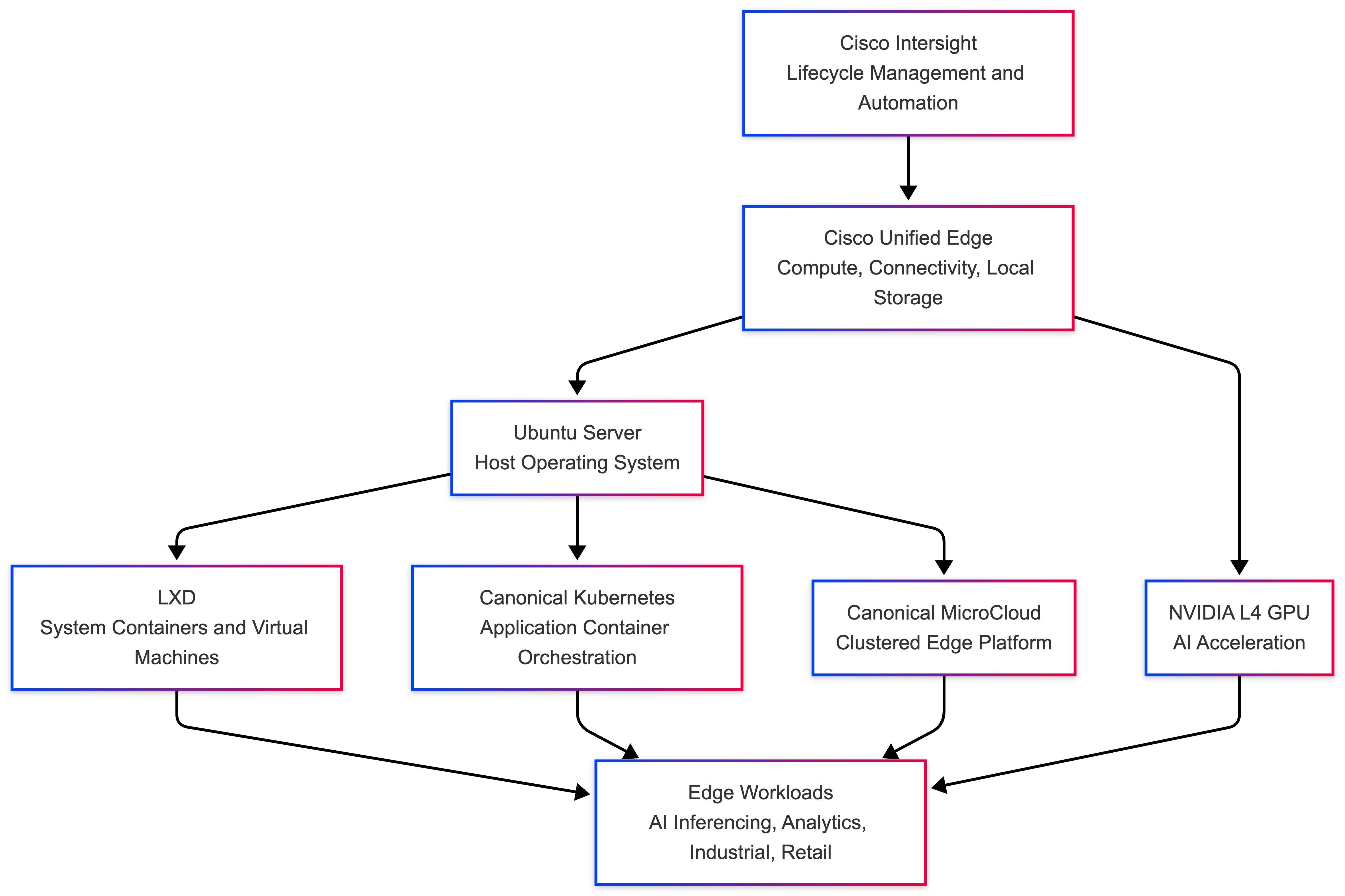
This solution provides a fully automated, scalable, and high-availability edge infrastructure built on Ubuntu, optimized for deployment on Cisco UCS / Intersight-managed servers. It enables seamless provisioning, containerization, orchestration, and distributed storage for modern edge workloads.
The design combines:
● Automated OS provisioning
● LXD-based system containers
● Canonical Kubernetes orchestration
● Ceph distributed storage
● High availability and live migration
Design Objectives
● Enable zero-touch provisioning using Ubuntu Autoinstall
● Provide a lightweight virtualization layer using LXD
● Support cloud-native workloads with Canonical Kubernetes
● Ensure high availability and fault tolerance
● Optimize for edge constraints (latency, bandwidth, footprint)
● Allow flexible deployment models (standalone > full HA cluster)
Architecture Components
● Provisioning Layer
● Ubuntu Autoinstall (Preseed-based automation)
● Cisco UCS / Intersight server bring-up
● Automated network, storage, and user configuration
Compute & Virtualization Layer
● MicroCloud multi-node platform
● System containers and VM support
● Live container migration across nodes
● Horizontal scalability
Storage Layer
● Ceph-backed distributed storage
● Block storage (RBD)
● Object storage (RGW)
● Shared filesystem (CephFS)
● Highly resilient and scalable storage for edge workloads
Container & Orchestration Layer
● Kubernetes deployment
● Multi-node Canonical Kubernetes clusters
● Integration with LXD VMs
● Supports cloud-native and AI workloads
High Availability Design
● Canonical Kubernetes HA using kube-vip
● LXD cluster-level fault tolerance
● Workload mobility via live migration
● Multi-node redundancy (3-node minimum recommended)
MicroCloud Integration
● Simplified deployment of:
● LXD
● Ceph
● Canonical Kubernetes
● Supports:
● Single-node deployments (dev/test)
● Multi-node HA clusters (production edge)
Deployment Models
● Model Description Use Case
● Standalone LXD Single-node deployment Dev / PoC
● MicroCloud Multi-node integrated edge platform
● Canonical Kubernetes Only Direct K8s deployment Cloud-native apps
● Full Edge HA Production Stack Microcloud + Canonical Kubernetes
Edge Deployment Considerations
● Low Latency: Local processing at edge nodes
● Offline Capability: Operates with intermittent connectivity
● Resource Efficiency: Lightweight stack (Canonical Kubernetes + LXD)
● Scalability: Add nodes dynamically
● Security: On-prem data processing
Key Capabilities
● Zero-touch infrastructure provisioning
● Unified compute + storage + orchestration stack
● High availability across edge nodes
● Seamless workload mobility
● Production-ready Kubernetes at the edge
The Cisco Unified Edge with Canonical solution provides an integrated architecture with Cisco and Canonical technologies that demonstrate support for bare-metal, virtual, and K8s workloads with high availability and server redundancy.
Figure 2 illustrates a sample design with the required management components, like Intersight Assist or Canonical Juju, installed outside of the solution stack.
This section outlines the key design requirements and prerequisites necessary for delivering the Cisco Unified Edge with Canonical solution.
The solution is designed to support a wide range of deployment models, scalability levels, and operational use cases at the edge providing flexibility, resiliency, and simplified lifecycle management.
The following are the general design requirements for this solution:
Note: This deployment model does not include integrated high availability (HA) at either the hardware or software layer.
● Simple Single-Node Deployment for Bare Metal, Virtual Machines, and Containers
◦ Provides a lightweight and easy-to-deploy edge platform capable of running bare-metal applications, virtual machines (VMs), and containerized workloads.
◦ Ideal for environments where footprint, cost, and simplicity are key priorities.
● Single-Node Kubernetes Deployment
◦ Offers a minimal, single-node Kubernetes environment (for example, Canonical Kubernetes ) for container orchestration at the edge.
◦ Suitable for small-scale edge applications, local AI inference, and test or pilot environments.
● Multi-Node Deployment for Bare Metal, Virtual Machines, and Containers
◦ Enables a scalable and resilient multi-node architecture supporting both traditional and cloud-native workloads.
◦ Designed for high availability and fault tolerance with no single point of failure across the infrastructure layers.
◦ Allows horizontal scalability by adding compute or storage nodes on demand as workload or business requirements evolve.
● Modular and Repeatable Design
◦ Provides a modular architecture that can be replicated across multiple edge locations or scaled to meet increasing business demands.
◦ Ensures consistent deployment experience through automation tools such as Cisco Intersight, Canonical MAAS, and Juju.
● Flexible and Extensible Architecture
◦ Offers the flexibility to integrate components beyond those validated and documented in this guide, allowing for future expansion.
◦ Supports interoperability with third-party systems, additional Canonical services (for example, Landscape, MicroCloud), and Cisco ecosystem solutions (for example, SecureX, Intersight Workload Optimizer).
This Cisco Unified Edge solution comes as an integrated stack with compute, storage and network and is connected to an external network domain. The compute nodes are configured to install the Ubuntu Server operating system on the local M.2 storage protected with RAID1. The persistent storage for bare-metal applications, Virtual machines and containers is provisioned on the local E3.s NVMe storage devices. The Unified Edge system is managed through Cisco Intersight Infrastructure Manager (IMM).
A typical topology for the Unified Edge based solution is shown in Figure 3.
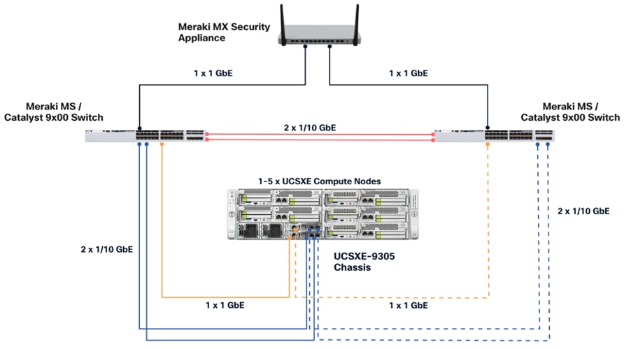
As the key components to deploy the solution are inside the Unified Edge chassis itself, there are some decisions to make regarding the connectivity to the external network:
● Both Edge Chassis Management Controller must be connected with their management network port to a network reaching the Intersight.com.
● Both Edge Chassis Management Controller must be connected with port 1 or port 2 to the network for data traffic.
● Both network devices on the UCS-XE130e compute node should be used with the same vSwitch / bond as uplink to provide high-availability.
● Canonical Ubuntu and LXD software can be installed on Cisco Unified Edge Compute Nodes with local disks.
● A Software Defined Storage option, like Ceph, must be used to create a multi-node storage platform for virtual machines, containers, and data.
Connectivity Inside the Chassis
The Cisco UCSXE-9305 chassis in this design is populated with up to five Cisco UCSXE servers. Each server is equipped with two 25-Gbps NICs connected to the midplane. One NIC connects to the embedded 25-Gbps switch on the first ECMC controller, and the second NIC connects to the embedded 25-Gbps switch on the second ECMC controller.
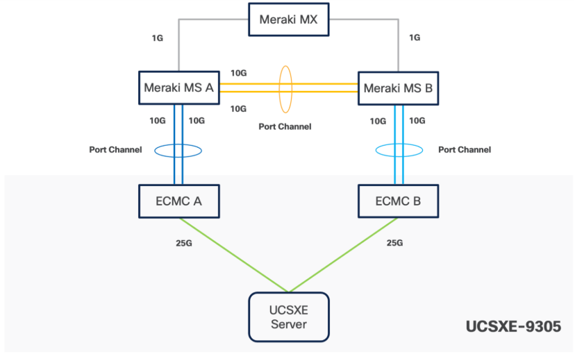
Ubuntu can configure the two NICs either as independent interfaces or combine them into a single bonded interface:
● When used independently, the server provides an aggregated bandwidth of 50 Gbps to the chassis.
● For bonded configurations, Active-Backup mode is recommended to ensure high availability and simpler failover behaviour.
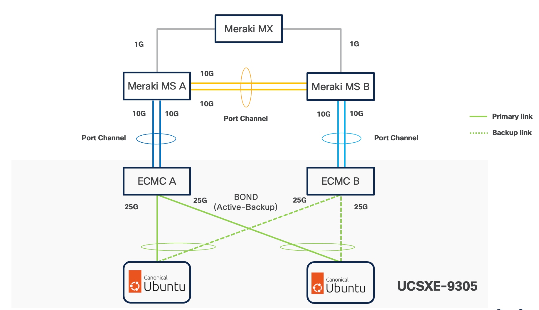
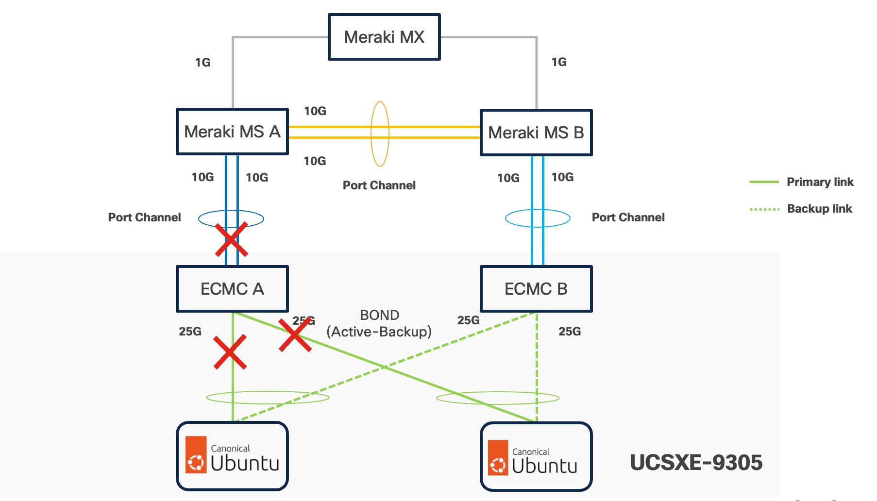
Ubuntu supports bonding through Netplan, and Active-Backup (mode=1) is the recommended option. This mode ensures:
● Simplified redundancy without switch-side link aggregation.
● Predictable network traffic behavior.
● Automatic failover when a link becomes unavailable.
For consistent traffic distribution across servers, the primary link interface should be set to point to the same ECMC on all servers. This keeps Layer-2 traffic within the chassis and reduces unnecessary external switching.
VLAN Configuration
Table 1 lists the VLANs which can be used for setting up the solutions along with their usage. As the bare minimum one VLAN-ID must be specified inside Cisco Unified Edge for internal communication and mapped as Native-VLAN to allow network traffic to the next-hop switch without VLAN tagging. The list in only an example and some of the VLANs are used in the deployment guide(s) based on this design document.
If no VLAN ID is used in the local network, set the Native-VLAN ID to any number between 4 and 4000 and define the IB-Management VLAN with the same ID.
| VLAN ID |
Name |
Usage |
| 5 |
Native-VLAN |
Use VLAN 5 as native VLAN instead of default VLAN (1). |
| 1320 |
OOB-MGMT-VLAN |
Out-of-band management VLAN to connect management ports for various devices. |
| 1321 |
IB-MGMT-VLAN |
In-band management VLAN utilized for all in-band management connectivity - for example, Linux hosts, management tools, and so on. |
| 1322 |
DATA-VLAN |
Data traffic VLAN for bare-metal applications, virtual machines, and containers. |
| 1323 |
VM-VLAN |
Data traffic VLAN from/to Virtual Machines. |
| 1324 |
CONTAINER-VLAN |
Data traffic VLAN from/to containers. |
| 3020 |
STORAGE-VLAN |
Storage replication traffic VLAN for SDS like Ceph. |
| 3030 |
CLOCK-VLAN |
Clock synchronization VLAN for manufacturing applications. |
| 3040 |
APP1-VLAN |
Dedicated VLAN for Application 1 Use-case, such as App to DB traffic. |
| 3050 |
APP2-VLAN |
Dedicated VLAN for Application 2 Use-case, such as Sensor to App traffic. |
| 3999 |
GUEST-VLAN |
VLAN ID for guests or Hotspot WiFi. |
Some of the key highlights of VLAN usage are as follows:
● VLAN 1320 allows customers to manage and access out-of-band management interfaces of various devices and is brought into the infrastructure to allow IMC access to the Unified Edge eCMC or Catalyst devices and is also available to infrastructure virtual machines (VMs). Interfaces in this VLAN are configured with MTU 1500.
● VLAN 1321 is used for in-band management of VMs, hosts, and other infrastructure services. This VLAN is also required to use vMedia policy and CIMC-Mounted ISO images inside Unified Edge. Interfaces in this VLAN are configured with MTU 1500.
● VLAN 1322 is the default VLAN used to access applications, use-cases, and traditional data traffic. Interfaces in this VLAN are configured with MTU1500.
● VLAN 1323 is used to access applications, use-cases, and traditional data traffic deployed on virtual machines. Interfaces in this VLAN are configured with MTU1500.
● VLAN 1324 is used to access applications, use-cases, and traditional data traffic deployed in containers. Interfaces in this VLAN are configured with MTU1500.
● VLAN 3020 is configured to allow storage replication traffic between the nodes. Interfaces in these VLANs are configured with MTU 9000.
● VLAN 3030 is used to by Industrial Edge applications to synchronize the clock and time information for critical command traffic. Interfaces in this VLAN are configured with MTU1500.
● VLAN 3040 is used to access a specific application or use-case like application to database traffic for a multi-tier application. Interfaces in this VLAN are configured with MTU1500.
● VLAN 3050 is used to access a specific application or use-case like data traffic from sensors to the data collector application. Interfaces in this VLAN are configured with MTU1500.
● VLAN 3999 is used for Guest access to the internet. Interfaces in this VLAN are configured with MTU1500.
Physical Components
The list of the required hardware components used to build a validated solution contains the Cisco Unified Edge components and the used network domain, see Table 2. You are encouraged to review their requirements and adjust the size or quantity of various components as needed.
Table 2. Unified Edge with Network Domain hardware components
| Component |
Hardware |
Comments |
| Cisco Unified Edge Chassis with two eCMCs |
Cisco UCS-XE 9305 Chassis with two eCMC |
The Unified Edge Chassis with the eCMC is the core of the solution design. |
| Cisco Unified Edge Compute nodes |
One to five Cisco UCS-XE130c compute nodes |
Your requirements will determine the amount of compute nodes required to build the solution. |
| Cisco Meraki Network Domain |
One or two Meraki Switches (MS). One or two Meraki Appliances (MX). |
Your requirements will determine the switch model and the amount of network ports and network speed required to build the solution. At least one Meraki MX device is required for remote locations to access the internet or the corporate network. |
| Cisco Catalyst Network Domain |
One or two Cisco Catalyst 9000 series Switches. One or two Cisco Catalyst 8000 series routers. |
Your requirements will determine the switch model and the amount of network ports and network speed required to build the solution. At least one Catalyst router is required for remote locations to access the internet or the corporate network. |
| Management Cluster |
||
| Hosted at a central place like the core data center. |
A minimum of two Cisco UCS servers to host components like DNS, Intersight Assist Juju Server, MaaS Server, and others. |
To reduce the number of physical servers the use of a supported virtualization software like KVM is recommended. |
Software Components
Table 3 lists various software components used in the solution.
Table 3. Software components and versions
| Component |
Version |
| Cisco Unified Edge Firmware Package |
6.0(1) |
| Cisco Catalyst 8000 |
IOS-XE |
| Cisco Catalyst 9000 |
IOS-XE |
| Cisco Meraki MX |
MX 18.211.6 |
| Cisco Meraki MS |
CS 17.2.2 |
| Canonical Ubuntu Server |
24.04.4 LTS |
| Canonical LXD |
5.21 (stable) |
| Canonical MicroCloud |
2.1.3 LTS |
| Canonical Kubernetes |
1.35 |
| Canonical Management Tools |
|
| Canonical Juju |
3.6.12 |
The Cisco Unified Edge with Canonical solution provides a flexible and automated deployment architecture designed to support a wide range of edge computing scenarios.
All deployments are fully automated through Cisco Intersight using Blueprints or custom workflows, ensuring consistent configuration, simplified operations, and lifecycle management.
The automation is based on the design and configuration principles defined in this guide and its associated deployment documents.
To support various deployment use cases, this design guide includes the following logical design options:
● Single-Node Canonical Ubuntu Server with LXD
◦ Provides lightweight container-based virtualization using LXD for edge workloads on a single node.
● Single-Node Canonical Ubuntu Server with LXD and Canonical Kubernetes
◦ Supports mixed workload environments using system containers (via LXD) and Kubernetes-orchestrated application containers (via Canonical Kubernetes) on a single host, suitable for legacy system workloads and modern cloud-native applications coexisting at the edge.
● Multi-Node Cluster with Canonical MicroCloud
◦ Delivers a highly available and self-managing multi-node cluster that can host virtual machines and containers with built-in replication, resilience, and scale-out capability.
● Single-Node Canonical Ubuntu Server with Canonical Kubernetes
◦ Offers a minimal Kubernetes environment via Canonical Kubernetes on a single node, ideal for small-scale edge applications or development and testing environments.
● Multi-Node Cluster with Canonical Kubernetes
◦ Enables distributed, production-grade Kubernetes clusters with high availability, horizontal scaling, and lifecycle automation using Juju and Intersight.
The logical configuration of the Cisco Unified Edge system may vary depending on the intended workload and solution architecture. For example:
● Deploying three standalone single-node Ubuntu servers running independent workloads does not require a dedicated storage replication network.
● Conversely, deploying a three-node Canonical MicroCloud cluster benefits from a dedicated storage and replication network to optimize data synchronization, fault tolerance, and performance
This flexible design approach ensures that the Cisco Unified Edge platform can be optimized for a variety of edge computing use cases from lightweight single-node deployments to robust, clustered multi-node environments with full redundancy and high availability.
Ubuntu Autoinstall with Edge-Ready Configuration
This section provides the configuration details.
Option 1
This approach uses Ubuntu autoinstall with cloud-init to automate operating system provisioning and prepare the system for edge workloads. The operating system is installed first, and container and cluster prerequisites are configured during post-installation.
1. Disk Partitioning (boot, root, data)
Disk partitioning is defined in the autoinstall configuration to separate system and workload data.
Desired Layout
● /boot – Boot partition
● / – Root filesystem
● /data – Dedicated data partition for containers and workloads
Example Storage Configuration
storage:
config:
- type: disk
id: disk0
match:
size: largest
ptable: gpt
wipe: superblock
- type: partition
id: boot-part
device: disk0
size: 1G
flag: boot
- type: partition
id: root-part
device: disk0
size: 50G
- type: partition
id: data-part
device: disk0
size: -1
- type: format
volume: boot-part
fstype: ext4
- type: format
volume: root-part
fstype: ext4
- type: format
volume: data-part
fstype: ext4
- type: mount
device: boot-part
path: /boot
- type: mount
device: root-part
path: /
- type: mount
device: data-part
path: /data
2. OS Initialization (Timezone, Locale)
System initialization parameters are defined to ensure consistency across edge locations:
locale: en_US.UTF-8
timezone: UTC
3. Hostname Configuration
Each node is assigned a unique hostname to support identification in clustered deployments:
identity:
hostname: ue-node-01
4. User Creation and Sudo Access
An administrative user is created during installation and granted sudo privileges:
identity:
username: admin
password: "$6$REDACTED_HASH"
Ubuntu automatically assigns sudo access to the primary user created during installation.
5. SSH Key–Based Access
Secure remote access is enabled using SSH public keys:
ssh:
install-server: true
authorized-keys:
- ssh-rsa AAAAB3NzaC1yc2EAAAADAQABAAABAQD...
Password-based SSH login can be disabled post-installation if required.
6. Network Interface Configuration
Network interfaces are configured using Netplan. Basic IP addressing can be applied during autoinstall or left for post-install configuration:
network:
version: 2
ethernets:
eno1:
dhcp4: true
7. VLAN Basics (Mgmt / Data / Storage)
VLAN interfaces are created to logically separate traffic:
network:
version: 2
ethernets:
eno1:
dhcp4: no
vlans:
mgmt:
id: 100
link: eno1
dhcp4: true
data:
id: 200
link: eno1
dhcp4: true
storage:
id: 300
link: eno1
dhcp4: true
This configuration supports management, application, and storage traffic isolation.
8. Ubuntu Tuning & Optimization for Edge Workloads
Basic OS tuning is applied during post-installation to optimize the system for edge use cases.
Example Late Commands
late-commands:
- curtin in-target -- systemctl disable apt-daily.service
- curtin in-target -- systemctl disable apt-daily-upgrade.service
- curtin in-target -- sysctl -w net.ipv4.ip_forward=1
- curtin in-target -- sysctl -w net.bridge.bridge-nf-call-iptables=1
These settings improve system stability, networking behavior, and readiness for container and Kubernetes workloads.
9. Installing LXD and Container Prerequisites
LXD and container prerequisites are installed as post-installation steps:
late-commands:
- curtin in-target -- snap install lxd
- curtin in-target -- lxd init --auto
- curtin in-target -- apt-get update
- curtin in-target -- apt-get install -y docker.io
Kubernetes itself is installed after the operating system boots to maintain a clean separation between OS and platform layers.
10. Post-Installation Validation (Test First)
After the system boots, validate the desired state:
lsb_release -a
df -h
ip addr
lxc list
docker version
Successful validation confirms the system is ready for Kubernetes or MicroCloud enablement.
Here is the complete cloud-init configuration:
#cloud-config
autoinstall:
version: 1
identity:
hostname: ue-node-01
username: admin
password: "$6$REDACTED_HASH"
locale: en_US.UTF-8
timezone: UTC
ssh:
install-server: true
allow-pw: false
authorized-keys:
- ssh-rsa AAAAB3NzaC1yc2EAAAADAQABAAABAQD...
storage:
config:
- type: disk
id: disk0
match:
path: /dev/sda
ptable: gpt
wipe: superblock
- type: partition
id: boot-part
device: disk0
size: 1G
flag: boot
- type: partition
id: root-part
device: disk0
size: 50G
- type: partition
id: data-part
device: disk0
size: -1
- type: format
volume: boot-part
fstype: ext4
- type: format
volume: root-part
fstype: ext4
- type: format
volume: data-part
fstype: ext4
- type: mount
device: boot-part
path: /boot
- type: mount
device: root-part
path: /
- type: mount
device: data-part
path: /data
network:
version: 2
ethernets:
eno1:
dhcp4: true
packages:
- curl
- ca-certificates
- gnupg
- containerd
late-commands:
# OS tuning
- curtin in-target -- sysctl -w net.ipv4.ip_forward=1
- curtin in-target -- modprobe br_netfilter
- curtin in-target -- sysctl -w net.bridge.bridge-nf-call-iptables=1
# Disable apt timers (correct way)
- curtin in-target -- systemctl disable apt-daily.timer
- curtin in-target -- systemctl disable apt-daily-upgrade.timer
- curtin in-target -- systemctl stop apt-daily.timer
- curtin in-target -- systemctl stop apt-daily-upgrade.timer
# Install LXD
- curtin in-target -- snap install lxd
- curtin in-target -- lxd init --storage-backend=dir --storage-create-device=/data
# Enable containerd
- curtin in-target -- systemctl enable containerd
Automated Cisco UCS / Intersight Server Bring-Up
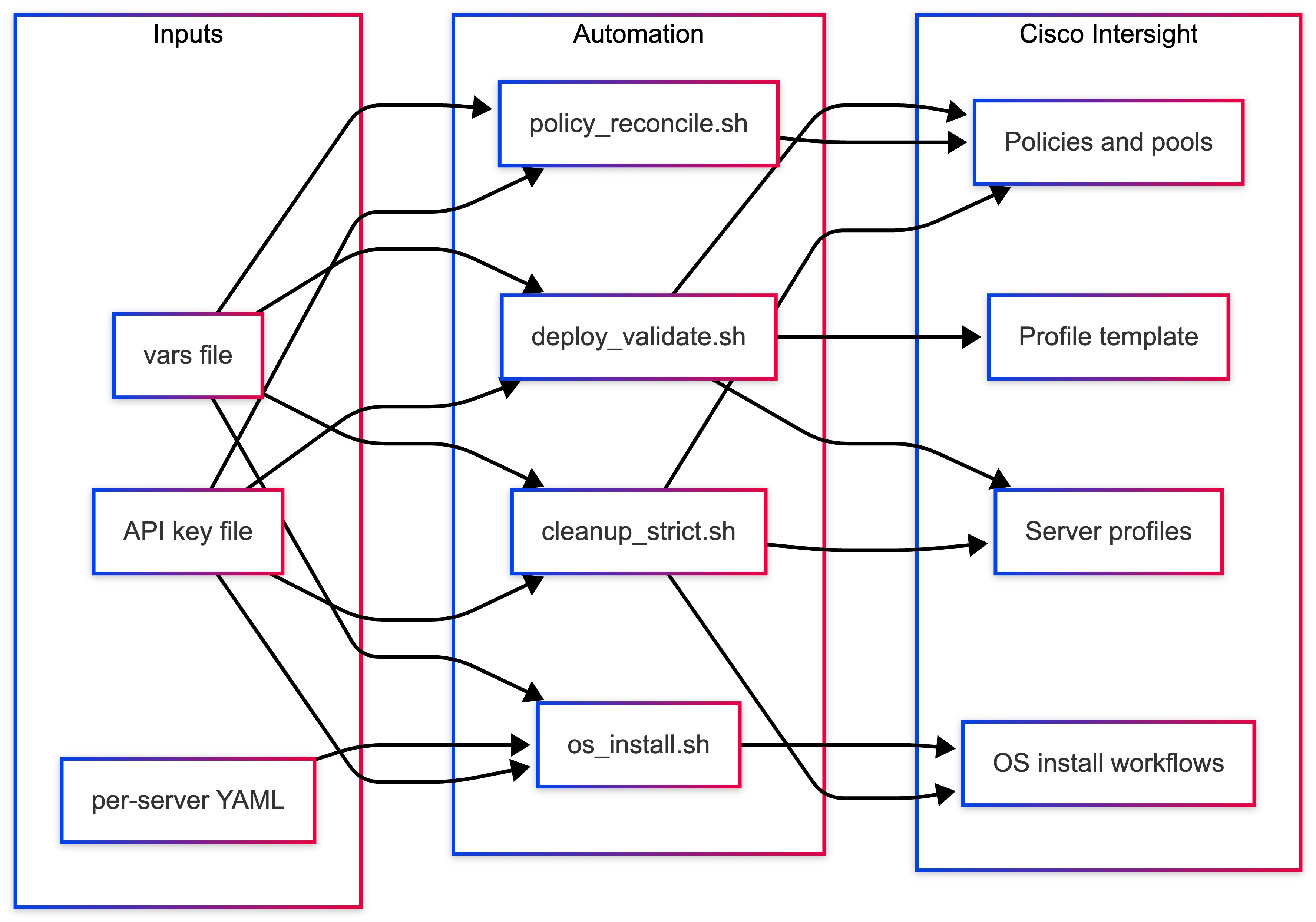
Option 2 – Recommended
This section describes an automated approach to provisioning Cisco Unified Edge servers using Cisco Intersight, including:
● Policy creation
● Server profile deployment
● Unattended Ubuntu OS installation
The solution uses a small set of scripts and a centralized variables file to ensure consistent, repeatable infrastructure deployment without relying on manual GUI workflows.
Automate end-to-end server provisioning—from infrastructure policies to OS installation—using a single variable file and reusable scripts, eliminating repetitive manual configuration in the Intersight UI.
Why this matters
Think of Cisco Intersight as the control plane for your entire server fleet.
Traditionally, administrators manually create:
● Policies (network, boot, storage)
● Pools (IP, MAC, UUID)
● Server profiles
● OS installation workflows
This approach replaces manual steps with:
● Infrastructure-as-Code (IaC) principles
● Centralized configuration (variables file)
● Repeatable automation scripts
Result
● Faster deployments
● Consistent configurations
● Reduced human error
● Easier audits and reviews
Daily workflow
After initial setup, day-to-day operations are minimal:
● Edit one variable file.
● Optionally update per-server YAML files.
● Run one script for infrastructure.
● Run one script for OS installation.
Where complexity exists
Initial setup requires understanding:
● VLANs, gateways, and IP addressing
● NIC naming as seen by Ubuntu (for example, eno1np0)
● Intersight policies and resource groups
● Secure handling of API keys and credentials
Solution Components
Table 4 lists the high-level structure for the artifact and role. You can download the files from UCS Solution git repository. For repository information, see UE_Ubuntu_Solutions.
| Artifact |
Role |
| intersight_deploy_validate_vars.txt |
Central configuration (single source of truth) |
| intersight_deploy_validate.sh |
Creates policies, templates, and server profiles |
| intersight_os_install.sh |
Automates OS installation workflows |
| intersight_policy_reconcile.sh |
Detects and optionally fixes configuration drift |
| intersight_cleanup_strict.sh |
Safely removes all objects created in the org |
| ubuntu-24.04.4-server*.yaml |
Per-server unattended OS install configs |
Key Design Principle
All infrastructure design decisions are encoded once in:
● Variables file > infrastructure configuration
● YAML files > OS-level configuration
This separation ensures:
● Clean abstraction
● Easier debugging
● Reusable infrastructure templates
Prerequisites
Platform Requirements
● Cisco Intersight account with required permissions
● Target organization and resource group configured
● Cisco UCS servers claimed and visible
System Requirements (Automation Host)
● bash
● isctl (Intersight CLI)
● jq
● Network connectivity to Intersight API
Security Requirements
● API key stored securely (referenced via SECRET_KEY_PATH)
● Key file must never be committed to source control
Infrastructure Requirements
● Available unassigned servers
● Reachable Ubuntu ISO URL (for vMedia boot)
● Defined VLAN and IP addressing scheme
End-to-End Deployment Workflow
This section details the end-to-end deployment workflow process.
Phase A – Configuration
Step 1: Configure Variables File
Edit:
intersight_deploy_validate_vars.txt
Set:
● Organization name
● Resource group
● API key path
● Number of server profiles (1–5)
● VLANs, IP ranges, MAC pools
● Boot policy and vMedia ISO
Step 2: Configure Per-Server YAML
Edit:
ubuntu-24.04.4-server1.yaml
...
ubuntu-24.04.4-server5.yaml
Define per server:
● Hostname
● Bonding configuration
● VLAN IPs
● DNS and routes
Note: Ensure the NIC names match actual system interfaces.
Phase B – Infrastructure Deployment
Run:
chmod +x intersight_deploy_validate.sh
./intersight_deploy_validate.sh intersight_deploy_validate_vars.txt /path/to/SecretKey.txt
Expected outcome
● Policies created
● Pools configured
● Profile template created
● Server profiles deployed and activated
● Validation checks completed
● Servers are ready for OS installation
Phase C – Operating System Installation
Run:
chmod +x intersight_os_install.sh
./intersight_os_install.sh intersight_deploy_validate_vars.txt /path/to/SecretKey.txt
Expected Outcome
● OS configuration files uploaded
● Installation workflows triggered
● Progress monitored automatically
● Ubuntu installed with predefined configuration
Optional – Drift Detection
./intersight_policy_reconcile.sh vars.txt key.txt
Ensures configuration consistency.
Optional – Cleanup (Lab Environments)
./intersight_cleanup_strict.sh vars.txt key.txt
Removes all objects created within the organization.
Logical Architecture
Figure 6 illustrates the logical architecture flow.
Benefits of this approach
Operational Advantages
● Repeatable deployments across environments
● Infrastructure as Code alignment
● Parallel provisioning and activation
● Reduced manual effort
● Faster time to deployment
Design Advantages
● Separation of infrastructure and OS logic
● Centralized configuration management
● Easy scaling (1 to N servers)
● Controlled lifecycle (deploy > validate > install > cleanup)
Security Considerations
● Store API keys and credentials outside version control
● Use environment variables or secret management systems (Vault, and so on)
● Rotate credentials regularly
● Restrict access to scripts that modify or delete infrastructure
● Audit usage of automation scripts
Ease of Adoption (CVD Positioning)
Strengths
● Highly repeatable and consistent
● Fully automates day-0 provisioning
● Aligns with enterprise IaC practices
● Supports parallel server provisioning
● Clean separation of responsibilities
Considerations
● Requires correct initial network design
● Depends on Intersight API and CLI setup
● YAML must match real hardware interfaces
● Secrets must be managed securely
Summary
This automation framework enables end-to-end server provisioning using Cisco Intersight, combining:
● Infrastructure automation
● Profile-based deployment
● Unattended OS installation
The result is a scalable, repeatable, and enterprise-ready edge deployment model that significantly reduces manual effort while improving consistency and reliability.
LXD Deployment Options for Edge Workloads
LXD provides system container and virtual machine orchestration capabilities on Ubuntu Server. In edge computing environments, LXD enables lightweight workload hosting, secure isolation, and infrastructure consolidation on resource-constrained hardware.
By running workloads inside LXD virtual machines, organizations can deploy microservices, edge analytics, and Kubernetes clusters directly on Cisco Unified Edge platforms without requiring a full hypervisor infrastructure.
This section describes the supported LXD deployment options, configuration models, storage backends, networking modes, and runtime capabilities, along with their suitability for edge computing use cases.
LXD Installation Methods
Snap Installation (Recommended)
snap install lxd
Description
LXD is distributed and maintained by Canonical as a Snap package, which provides an integrated installation, update mechanism, and dependency management system.
This method ensures the deployment remains aligned with Canonical's supported release channels and simplifies lifecycle management for infrastructure administrators.
Advantages
● Officially supported by Canonical
● Automated updates and patching
● Integrated VM support using QEMU
● Built-in clustering capabilities
● Simplified upgrade and rollback mechanisms
● Consistent package distribution across nodes
Recommended Use Cases
Snap-based LXD installation is recommended for:
● Production edge deployments
● Kubernetes container infrastructure
● MicroCloud environments
● Multi-node edge clusters
● Automated edge orchestration platforms
LXD Operating Modes
LXD supports two primary deployment models depending on the scale and availability requirements of the edge environment.
Standalone Mode (Single Node)
lxd init
clustering = no
Description
Standalone mode deploys LXD on a single host, where all containers and virtual machines run locally.
Note: This model is ideal for small edge deployments where simplicity and minimal infrastructure dependencies are required.
Edge Use Cases
Typical use cases include:
● Retail branch edge servers
● Industrial IoT gateways
● Manufacturing edge analytics
● AI inference nodes
● Remote branch compute platforms
Advantages
● Minimal configuration complexity
● No inter-node communication required
● Reduced network requirements
● Simplified operations and troubleshooting
● Lower infrastructure overhead
Position
Standalone LXD deployments represent the default validated architecture for single-node edge environments in this design.
Cluster Mode (Multi-Node)
lxd init
clustering = yes
Description
Cluster mode enables multiple LXD nodes to operate as a unified infrastructure cluster. Containers and virtual machines can be scheduled across nodes, enabling horizontal scaling and workload mobility.
Requirements
Cluster deployments require:
● Static IP addresses for all cluster nodes
● Port 8443/TCP open for LXD API communication
● TLS trust between cluster members
● Consistent storage backend configuration
● Reliable network connectivity between nodes
Edge Use Cases
Cluster deployments are recommended for:
● High availability edge platforms
● Distributed edge clouds
● Multi-site orchestration
● Edge infrastructure pools
Advantages
● Workload migration between nodes
● Improved infrastructure utilization
● Horizontal scaling capabilities
● Fault tolerance and failover support
Note: Cluster mode is supported in this design, but requires additional planning around networking, storage, and operational procedures.
Note: It is highly recommended to use Microcloud when required.
LXD Storage Backend Options
Storage backend selection has a direct impact on performance, reliability, and operational complexity. The following options are supported.
Option 1 — Directory Backend (dir)
driver: dir
Description
The directory storage backend stores container data as standard directories within the host filesystem, typically on a dedicated mount point such as /data.
Advantages
● Simple configuration
● No specialized disk preparation required
● Compatible with existing filesystems
● Easy backup and migration
● Low operational complexity
Limitations
● Snapshot operations are less efficient
● Performance lower than block-based storage
● Not optimized for large-scale container environments
Recommended Use Cases
This backend is recommended for:
● Single-node edge deployments
● Predictable workload environments
● Operational simplicity
Recommendation
The directory backend on a dedicated /data partition is the preferred storage model for single-node edge deployments.
Option 2 — ZFS
driver: zfs
Advantages
● Fast snapshot and cloning operations
● Copy-on-write filesystem
● Built-in compression and deduplication
● High performance storage operations
Requirements
● Dedicated disk or block device
● Higher memory overhead
● Careful storage planning
Recommended Use Cases
ZFS is suitable for:
● AI and analytics workloads
● Snapshot-intensive environments
● Performance-sensitive applications
Note: ZFS is supported but requires additional storage planning and validation.
Option 3 — LVM
driver: lvm
Advantages
● Block-level performance
● Thin provisioning support
● Mature Linux storage technology
Limitations
● Requires disk preparation and wiping
● Increased operational complexity
Note: LVM is not recommended for edge deployments unless enterprise storage architecture requires it.
Option 4 — Ceph (Cluster Deployments)
Description
Ceph provides distributed storage across multiple nodes and enables highly available storage pools.
Recommended Use Cases
Ceph is appropriate for:
● MicroCloud deployments
● Multi-node edge clusters
● High availability storage environments
Note: Ceph storage is outside the scope of the single-node deployment model described in this document.
Note: Microcloud is highly recommended whenever Ceph is needed, even in single node scenario.
LXD Networking Modes
Networking configuration determines how containers communicate with each other and with external systems.
NAT Bridge (lxdbr0)
Default LXD networking configuration.
Recommended for:
● Single node environments
● Isolated workloads
● Development and validation environments
VLAN Attached Bridge
Containers connect directly to enterprise VLANs.
Recommended for:
● Production workloads
● direct enterprise network integration
● environments requiring routable container IP addresses
Macvlan Networking
Provides containers with direct LAN presence.
Recommended for:
● Lightweight services
● environments requiring minimal networking configuration
Limitations include reduced host-container communication.
Overlay / Cluster Networking
Used in MicroCloud multi-node platform.
Recommended for:
● High availability environments
● distributed edge infrastructure
● MicroCloud deployments
Container versus Virtual Machine Mode
LXD supports both containerized workloads and full virtual machines.
System Containers (Default)
System containers provide lightweight Linux environments that share the host kernel.
Advantages
● Extremely fast startup times
● Low memory footprint
● High workload density
● Efficient CPU utilization
Edge Use Cases
● AI inference services
● retail microservices
● edge analytics pipelines
● data processing workloads
Virtual Machines
lxc launch ubuntu:24.04.4 vm1 --vm
Advantages
● Full operating system isolation
● Separate kernel environments
● Compatibility with legacy workloads
Edge Use Cases
● Vendor appliances
● Legacy enterprise software
● Windows workloads
Note: Virtual machines are supported but consume significantly more system resources.
Security and Exposure Options
LXD API Exposure
By default, the LXD API should not be exposed externally.
core.https_address = unset
External API exposure should only be enabled when clustering or remote orchestration is required.
Image Auto Updates
images.auto_update_interval = 6
This ensures container images remain up to date with security patches and OS updates.
Table 5. Edge Workload Suitability Matrix
| Deployment Type |
Storage |
Networking |
Mode |
| Single Edge Node |
dir |
NAT Bridge |
Standalone |
| Retail Edge |
dir |
VLAN Bridge |
Standalone |
| Industrial Gateway |
dir |
NAT Bridge |
Standalone |
| Multi-Node HA |
ZFS / Ceph |
Overlay |
Cluster |
| AI Edge Platform |
ZFS |
VLAN Bridge |
Standalone |
Recommended Configuration
For most Cisco Unified Edge single-node deployments, the following architecture is recommended:
● Snap-based LXD installation
● Standalone operating mode
● Directory storage backend using /data
● NAT-based container networking
● LXD API not externally exposed
● Container workloads preferred over virtual machines
This configuration provides the best balance of simplicity, reliability, and performance for edge environments.
Step 1 – Create Dedicated Storage for Container Workloads
During default Ubuntu installation, only a portion of disk capacity is allocated to the root filesystem. The remaining space can be used to create a dedicated logical volume for container storage.
Verify Volume Group
vgdisplay
Confirm available free space.
Create Logical Volume
Example allocation:
lvcreate -L 200G -n data-lv ubuntu-vg
Format the Logical Volume
mkfs.ext4 /dev/ubuntu-vg/data-lv
Create Mount Point
mkdir /data
Mount Logical Volume
mount /dev/ubuntu-vg/data-lv /data
Persist Mount Configuration
echo '/dev/ubuntu-vg/data-lv /data ext4 defaults 0 2' >> /etc/fstab
Verify:
mount -a
df -h
The /data partition is now ready for container storage.
Step 2 – Apply Production LXD Configuration
The following preseed configuration defines a production-ready single-node LXD environment optimized for edge workloads.
LXD Production Preseed YAML
config:
images.auto_update_interval: "6"
core.https_address: ""
core.trust_password: ""
networks:
- name: lxdbr0
type: bridge
config:
ipv4.address: 10.132.0.1/24
ipv4.nat: "true"
ipv6.address: "none"
storage_pools:
- name: default
driver: dir
config:
source: /data
profiles:
- name: default
description: Default profile for edge workloads
config:
security.nesting: "true"
security.syscalls.intercept.mknod: "true"
security.syscalls.intercept.setxattr: "true"
devices:
eth0:
name: eth0
network: lxdbr0
type: nic
root:
path: /
pool: default
type: disk
projects: []
cluster: null
Save as:
lxd-production.yaml
Apply Configuration
If LXD has not been initialized:
lxd init --preseed < lxd-production.yaml
If LXD was previously initialized:
snap remove lxd --purge
snap install lxd
lxd init --preseed < lxd-production.yaml
Step 3 – Validation
Verify storage configuration:
lxc storage show default
Expected output:
source: /data
Verify networking:
lxc network show lxdbr0
Launch validation container:
lxc launch ubuntu:24.04.4 test-container
lxc list
Table 6. Production Characteristics
| Component |
Configuration |
| Storage |
Dedicated /data logical volume |
| Storage Backend |
Directory driver |
| Networking |
NAT bridge |
| IPv6 |
Disabled |
| API Exposure |
Disabled |
| Image Updates |
Automatic |
| Mode |
Standalone |
Design Considerations for Edge Deployments
The following are the design considerations specific for Edge deployments:
● The /data partition must reside on reliable storage hardware.
● LXD bridge CIDR must not overlap with enterprise networks.
● Kubernetes pod CIDR must not conflict with the LXD network.
● Enterprise patch management policies must be considered.
Recommended Deployment Scenarios
This architecture is suitable for:
● Retail edge compute platforms
● Industrial IoT gateways
● AI inference nodes
● Remote branch compute infrastructure
● Single-node Kubernetes edge clusters
Live Workload Migration Across MicroCloud Nodes
After a multi-node MicroCloud environment is established, one of its key operational capabilities is workload mobility across cluster members. MicroCloud enables workloads to be moved between nodes with minimal service interruption when the underlying storage and networking configuration supports it.
This capability is particularly valuable in edge environments where infrastructure must remain available during:
● system maintenance
● hardware upgrades
● node failures
● workload rebalancing
Workload migration allows administrators to relocate services without rebuilding the application stack, helping maintain service continuity across the distributed edge infrastructure.
In this Cisco Validated Design, workload migration is validated within a three-node MicroCloud deployment on Cisco Unified Edge systems.
Migration Architecture
In a multi-node MicroCloud deployment, workloads run on top of the integrated platform formed by:
● LXD for compute
● MicroOVN for networking
● MicroCeph for distributed storage
When shared storage is available through MicroCeph, workloads can be moved between nodes more efficiently because storage remains accessible across the cluster. In environments using only local storage, migration requires data transfer between nodes and may involve greater disruption.
In most production scenarios, workload migration should be validated for the specific application before operational use.
Example Migration Workflow
1. A workload is running on one MicroCloud node.
2. The workload is moved to another node.
3. The application resumes on the destination node.
4. Application access is revalidated.
Migration Prerequisites
Before performing workload migration in a multi-node MicroCloud deployment, the following conditions must be met:
MicroCloud Environment
● MicroCloud cluster must be operational
● Nodes must be reachable over the cluster network
● Cluster services must be healthy
Verify cluster membership:
microcloud status
lxc cluster list
Storage Configuration
Workload migration works best when MicroCeph distributed storage is enabled.
For simple environments using local storage, workload data must be transferred during migration.
For production clusters, MicroCeph is recommended because it reduces disruption and improves recovery behavior.
Network Connectivity
All cluster members must be able to communicate with each other over the network.
MicroOVN networking and cluster communication must be functioning correctly.
Required cluster communication ports must be open according to the platform design.
Workload Migration Procedure
The following procedure demonstrates how to move a workload between nodes in a multi-node MicroCloud deployment.
Verify Workload Location
List running workloads and identify the current host:
lxc list
Example output:
NAME STATE IPV4 LOCATION web1 RUNNING 10.200.10.5 node1
In this example, the workload web1 is running on node1.
Initiate Migration
Move the workload to another node:
lxc stop web1 lxc move web1 --target node2 lxc start web1
During migration, the workload configuration is transferred to the destination node. When shared storage is available through MicroCeph, the migration process is more efficient because the underlying data remains accessible across the cluster.
Verify Migration Completion
Check workload placement again:
lxc list
Expected result:
NAME STATE IPV4 LOCATION web1 RUNNING 10.200.10.5 node2
The workload is now running on node2.
Validate Application Availability
To confirm service continuity, verify application accessibility after migration.
Example test:
curl >
The application should remain accessible after migration.
Cross-Node Migration Validation
Migration can be repeated across additional MicroCloud nodes to validate workload mobility.
Example:
lxc move web1 --target node3
Verify placement:
lxc list
The workload should now appear on node3.
Operational Use Cases
Workload migration enables several operational workflows.
Infrastructure Maintenance
Workloads can be moved off a node before performing maintenance tasks such as:
● firmware upgrades
● operating system updates
● hardware replacement
Workload Rebalancing
Administrators can redistribute workloads across nodes to optimize:
● CPU usage
● memory utilization
● storage capacity
Fault Avoidance
If a node experiences degraded performance, workloads can be moved proactively to healthy nodes.
Migration Performance Considerations
Migration duration depends on several factors (Table 7).
| Factor |
Impact |
| Workload memory usage |
Larger memory requires longer transfer time |
| Filesystem size |
Larger storage footprint increases transfer time |
| Network bandwidth |
Faster networks reduce migration duration |
| Storage model |
MicroCeph reduces data-copy overhead compared to local storage |
For optimal migration performance:
● use high-speed networking
● minimize workload disk footprint
● avoid migration during peak traffic periods
● use MicroCeph for shared storage
Limitations
Certain workloads may not support seamless migration.
Examples include:
● workloads with heavy disk I/O
● applications maintaining external hardware connections
● workloads with strict real-time constraints
These scenarios may require stop-and-start migration or workload restart on the destination node.
Production Recommendations
For production-grade multi-node MicroCloud deployments, the following design enhancements are recommended:
● enable MicroCeph distributed storage
● use 10GbE or higher networking between cluster nodes
● monitor cluster health and resource utilization
● validate migration behavior per application
● use Kubernetes for application-level orchestration where appropriate
These improvements reduce migration time and improve platform resiliency.
Validation Summary
Workload migration was successfully validated across the three-node MicroCloud deployment on Cisco Unified Edge systems.
Table 8 lists the confirmed capabilities.
Table 8. Validation Tests and Results
| Validation Test |
Result |
| Workload migration between nodes |
Successful |
| Application availability after migration |
Maintained |
| Cluster state synchronization |
Verified |
The test confirms that a multi-node MicroCloud deployment supports dynamic workload mobility, allowing administrators to maintain application availability during infrastructure operations.
Recommended Edge Architecture: MicroCloud with Canonical Kubernetes
Modern edge environments require infrastructure platforms that are lightweight, resilient, and operationally simple, while still supporting cloud-native application deployment models. Organizations increasingly deploy compute resources closer to data sources such as IoT devices, industrial sensors, cameras, and retail systems to enable low-latency processing and real-time analytics.
A combination of Canonical MicroCloud and Canonical Kubernetes provides a flexible and scalable platform for running workloads at the network edge.
In this architecture, MicroCloud provides the integrated infrastructure platform by combining compute, storage, and networking services across physical nodes. Canonical Kubernetes operates as the application orchestration layer, managing containerized workloads running on top of that infrastructure.
This design preserves a clear separation between infrastructure services and application orchestration while ensuring they function together as a unified edge platform. MicroCloud is not a separate management layer on top of compute, storage, and networking; it is the platform formed by those capabilities.
The architecture enables organizations to deploy cloud-native applications consistently across edge sites, data centers, and cloud environments.
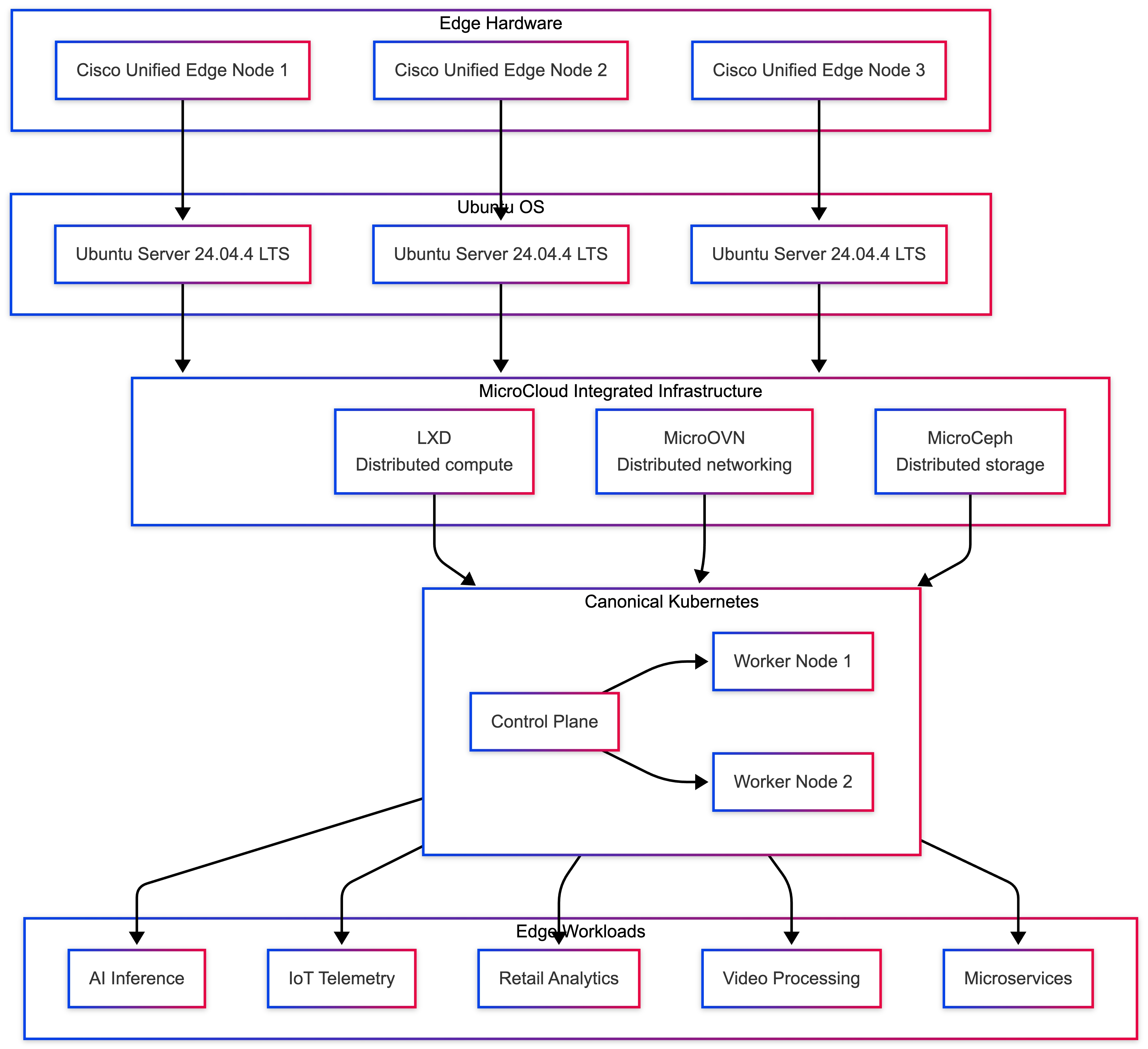
Table 9 lists the four logical layers, each providing a specific role within the platform of the solution architecture.
Table 9. Architecture Layers and Roles
| Layer |
Rose |
| Edge Hardware |
Provides compute, networking, and storage resources |
| Ubuntu OS |
Operating system foundation and system services |
| MicroCloud |
Integrated distributed compute, storage, and networking platform |
| Canonical Kubernetes |
Application orchestration and service management |
Each layer contributes distinct capabilities to the overall system architecture.
Infrastructure Layer: MicroCloud
MicroCloud provides distributed edge infrastructure across multiple Cisco Unified Edge servers. It integrates LXD for compute, MicroOVN for networking, and MicroCeph for storage into a single platform that can be deployed and operated consistently across edge locations.
Key capabilities provided by the MicroCloud infrastructure layer include:
● Multi-node infrastructure clustering
● Distributed compute services through LXD
● Integrated networking through MicroOVN
● Distributed storage through MicroCeph
● Cluster-wide workload placement
● Centralized infrastructure visibility
● Secure isolation for containers and virtual machines
● Infrastructure resilience across physical nodes
MicroCloud allows the platform to continue operating even if an individual node becomes unavailable, provided quorum is maintained (Table 10).
Table 10. Example Cluster Layout
| Node |
Role |
| node1 |
MicroCloud cluster member |
| node2 |
MicroCloud cluster member |
| node3 |
MicroCloud cluster member |
For production deployments, a minimum of three nodes is recommended to maintain quorum and ensure reliable high-availability operations.
Canonical Kubernetes Layer
Canonical Kubernetes operates as the application orchestration layer within the platform. It manages containerized workloads, service discovery, scaling, and application lifecycle operations.
In this architecture, Kubernetes nodes run on infrastructure provided by MicroCloud, allowing the application layer to benefit from distributed compute, integrated networking, and resilient storage services.
Table 11. Example Kubernetes Node Layout
| Node / Instance |
Role |
| k8s-control-1 |
Kubernetes control plane |
| k8s-control-2 |
Kubernetes control plane |
| k8s-control-3 |
Kubernetes control plane |
The control plane node manages cluster state, scheduling, and API access, while worker nodes execute application workloads.
Canonical Kubernetes simplifies deployment and operations while maintaining full upstream Kubernetes compatibility, making it well suited for edge environments that require consistency and reduced operational overhead.
Workload Placement
One of the key benefits of MicroCloud is the ability to distribute workloads across multiple physical hosts while maintaining consistent infrastructure services.
Table 12 lists an example of the workload placement.
| Kubernetes Node / Instance |
Host Location |
| k8s-control-1 |
node1 |
| k8s-control-2 |
node2 |
| k8s-control-3 |
node3 |
This distribution ensures that Kubernetes components are not all hosted on the same physical system, improving fault tolerance and overall resiliency. If a single infrastructure node becomes unavailable, the remaining nodes in the cluster can continue operating.
Network Architecture
Networking is implemented through multiple layers that provide connectivity between infrastructure components and Kubernetes workloads.
Table 13. Network Layers and Function
| Layer |
Function |
| Physical Network |
Provides connectivity between edge nodes |
| MicroOVN Network |
Enables distributed node-to-node and workload connectivity |
| Instance Interface |
Connects workloads to MicroCloud networking |
| Kubernetes Pod Network |
Handles pod-to-pod communication |
MicroCloud networking enables workloads and infrastructure services across different hosts to communicate consistently, while Kubernetes manages service-level communication between application pods.
This layered approach ensures reliable communication across both infrastructure and application layers.
Storage Architecture
Storage can be implemented using local or distributed options depending on deployment requirements.
Table 14. Supported Storage Options
| Storage Type |
Use Case |
| ZFS local storage |
Single-node or lab deployments |
| LVM storage |
High-performance local storage |
| MicroCeph distributed storage |
Multi-node high availability |
For multi-node production clusters, MicroCeph distributed storage is recommended. MicroCeph enables shared storage across nodes, allowing:
● workload migration
● infrastructure failover
● persistent data replication
● resilient stateful services
High availability in this architecture is achieved through multiple layers of redundancy and infrastructure resilience is provided through MicroCloud.
Key mechanisms include:
● multiple cluster nodes
● distributed control and service coordination
● workload placement across nodes
● integrated storage and networking resilience
● infrastructure failover capabilities
Canonical Kubernetes provides application-level resilience through:
● multiple worker nodes
● pod replication
● service load balancing
● self-healing capabilities
This layered redundancy helps ensure both infrastructure and applications remain operational during node failures.
Edge Workload Use Cases
The architecture supports a wide range of edge computing workloads.
Examples include:
● AI inference pipelines
● IoT telemetry processing
● retail analytics platforms
● video processing workloads
● microservices-based applications
● industrial automation services
Container-based and cloud-native workloads benefit from fast provisioning, efficient resource utilization, and flexible deployment options, making them well suited for distributed edge environments.
Operational Advantages
Deploying Canonical Kubernetes on MicroCloud infrastructure provides several operational benefits.
Key advantages include:
● simplified infrastructure provisioning
● integrated compute, storage, and networking services
● faster Kubernetes node deployment
● reduced operational complexity
● flexible workload placement across nodes
● consistent lifecycle management across edge sites
Because the underlying infrastructure is integrated within MicroCloud, organizations can scale and manage the platform more consistently than with separately assembled infrastructure layers.
Deployment Workflow
The recommended deployment workflow follows an integrated platform approach:
Deploy Ubuntu 24.04.4 LTS on Cisco Unified Edge servers.
● Install MicroCloud components on each node.
● Initialize a MicroCloud cluster across multiple edge nodes.
● Configure integrated networking and storage services.
● Deploy Canonical Kubernetes on top of the MicroCloud platform.
● Enable Kubernetes add-ons and deploy application workloads.
This approach ensures a consistent and repeatable deployment model for edge infrastructure.
Scaling the Architecture
The architecture supports scaling at both the infrastructure layer and the application layer.
Infrastructure Scaling
Additional compute, storage, and networking capacity can be added by introducing new MicroCloud cluster nodes.
Application Scaling
Kubernetes workloads can scale horizontally by adding worker nodes or application pods. Because the infrastructure platform is integrated and designed for distributed operation, scaling can be completed efficiently while maintaining consistency across the environment.
Validation Summary
A layered edge computing platform was successfully validated using Cisco Unified Edge systems running Ubuntu 24.04.4 LTS.
Table 15. Validation Tests and Results
| Validation Test |
Result |
| MicroCloud cluster deployment |
Successful |
| Canonical Kubernetes deployment |
Operational |
| Kubernetes cluster formation |
Successful |
| Application deployment |
Verified |
| Cross-node networking |
Functional |
| Distributed infrastructure services |
Functional |
The validation confirms that the architecture provides a scalable and resilient platform for running Kubernetes workloads at the edge.
Conclusion
The combination of MicroCloud and Canonical Kubernetes creates a flexible and efficient platform for deploying modern applications in distributed edge environments.
By leveraging Cisco Unified Edge hardware, Ubuntu Server, MicroCloud integrated infrastructure, and Canonical Kubernetes orchestration, organizations can deploy cloud-native applications closer to data sources while maintaining centralized operational control.
This architecture enables enterprises to support emerging workloads such as AI analytics, IoT processing, and distributed microservices with minimal infrastructure overhead.
Kubernetes Deployment on LXD VMs - Canonical Kubernetes for Edge
This section describes the deployment of Canonical Kubernetes inside LXD virtual machines on Cisco Unified Edge systems running Ubuntu Server 24.04.4 LTS.
Deploying Kubernetes inside LXD virtual machines provides a lightweight and flexible orchestration platform that is well suited for edge computing environments. Compared to running full traditional virtual infrastructure stacks, LXD virtual machines reduce operational overhead while maintaining strong workload isolation and deployment flexibility.
Canonical Kubernetes can be deployed on infrastructure provided by LXD. For production-grade deployments, LXD virtual machines are recommended for Kubernetes nodes because they provide stronger isolation and better alignment with current platform guidance.
LXD virtual machines enable rapid provisioning of Kubernetes nodes while maintaining efficient resource utilization on edge hardware platforms. This approach simplifies lifecycle management, allowing administrators to deploy, recreate, migrate, or scale Kubernetes nodes dynamically.
The validated architecture consists of the following infrastructure layers.
This architecture enables rapid Kubernetes deployment for edge workloads such as AI inference pipelines, IoT data processing, retail analytics, and distributed microservices.
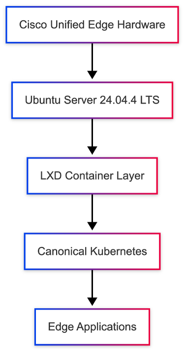
The Kubernetes deployment architecture validated in this design provides the following capabilities.
Lightweight Kubernetes Runtime
Canonical Kubernetes delivers a compact, production-ready Kubernetes distribution optimized for edge and small-cluster deployments.
VM-Based Node Provisioning
Kubernetes nodes are deployed as LXD virtual machines, allowing new nodes to be created quickly without requiring a separate virtualization stack.
Simplified Cluster Operations
Canonical Kubernetes packages the core Kubernetes services in a streamlined distribution, reducing operational complexity while preserving upstream Kubernetes compatibility.
Efficient Resource Utilization
Running Kubernetes nodes inside LXD virtual machines reduces infrastructure complexity while preserving strong workload isolation.
Architectural Limitations
The VM-based Kubernetes architecture intentionally prioritizes simplicity and lightweight operation. As such, the following advanced features are not included in this deployment:
● Multi-region Kubernetes federation
● Cross-cluster orchestration
● Multi-tenant infrastructure segmentation
Despite these limitations, Canonical Kubernetes provides an ideal runtime for single-node and small-cluster edge deployments.
Prerequisites
Before deploying Kubernetes inside LXD virtual machines, several prerequisites must be satisfied.
System Requirements
The following system resources are recommended for stable Kubernetes operation.
| Resource |
Recommended |
| CPU |
4 cores |
| Memory |
16 GB |
| Storage |
100 GB |
| Network |
Static IP configuration |
These resource allocations ensure that the host system can support both LXD infrastructure services and Kubernetes workloads.
Software Requirements
The following components must be installed and configured prior to Kubernetes deployment:
● Ubuntu Server 24.04.4 LTS
● LXD runtime
● Configured LXD storage pool
● LXD bridge network
Verify that LXD is operational:
lxc info
Create Kubernetes LXD Profile
Kubernetes virtual machines require a consistent LXD profile for networking, storage, and VM configuration.
Step 1 - Create the Kubernetes Profile
lxc profile create canonical-k8s
Step 2 - Attach Network Interface
Attach the VM network interface to the LXD bridge:
lxc profile device add canonical-k8s eth0 nic name=eth0 network=lxdbr0
Step 3 - Verify the Profile Configuration
lxc profile show canonical-k8s
Deploy Kubernetes Node VM
Once the profile is created, a virtual machine can be launched to act as a Kubernetes node.
lxc launch ubuntu:24.04.4 k8s-node --vm -p default -p canonical-k8s
Verify VM status:
lxc list
Expected output:
k8s-node RUNNING
Access the Kubernetes Node
Enter the virtual machine shell to install Kubernetes:
lxc exec k8s-node -- bash
Install Canonical Kubernetes
Inside the virtual machine, install Canonical Kubernetes:
snap install k8s --classic
Initialize the Kubernetes services and wait until the node is ready:
sudo k8s bootstrap sudo k8s status --wait-ready
This ensures that the Kubernetes control plane services are running correctly.
Enable Core Kubernetes Services
Canonical Kubernetes provides the core services required to run edge workloads.
Commonly required capabilities include:
● DNS for service name resolution
● ingress for HTTP traffic routing
● storage integration for persistent workloads
Verify the cluster is operational:
sudo k8s kubectl get nodes
Expected output:
NAME STATUS ROLES k8s-node Ready control-plane
The Kubernetes node is now registered and ready to run workloads.
Deploy Test Application
To validate Kubernetes functionality, deploy a sample application.
Create an nginx deployment:
sudo k8s kubectl create deployment nginx --image=nginx
Expose the application using a NodePort service:
sudo k8s kubectl expose deployment nginx --type=NodePort --port=80
Verify service status:
sudo k8s kubectl get svc
This confirms that Kubernetes workloads can be deployed and exposed successfully.
Validation Summary
The validation confirms that Canonical Kubernetes deployed inside LXD virtual machines provides:
● lightweight Kubernetes infrastructure for edge systems
● fast node provisioning through LXD virtual machines
● reduced infrastructure overhead
● simplified lifecycle operations
● reliable workload deployment on Cisco Unified Edge platforms
Edge Deployment Considerations
When deploying Canonical Kubernetes in edge environments, several design considerations must be addressed.
Resource Optimization
Edge systems typically operate with constrained resources. VM resource limits should be configured appropriately.
Example:
lxc config set k8s-node limits.cpu 4 lxc config set k8s-node limits.memory 8GB
These limits prevent Kubernetes workloads from consuming excessive host resources.
Security
Edge Kubernetes deployments must be secured to protect infrastructure and workloads.
Recommended security practices include:
● securing Kubernetes API endpoints
● restricting SSH access
● implementing Kubernetes RBAC policies
● limiting privileged workload usage
Network Planning
VM networking should align with the overall edge infrastructure design.
Bridge networking provides the simplest deployment model, while advanced environments may require:
● overlay networking
● software-defined networking (SDN)
● integration with enterprise network policies
Operational Benefits
Running Canonical Kubernetes inside LXD virtual machines offers several operational advantages:
● rapid node provisioning
● low resource overhead
● simplified lifecycle management
● efficient workload isolation
Virtual machines can be recreated or repositioned between cluster nodes, supporting dynamic edge workloads.
Expansion to Multi-Node Kubernetes
Additional Kubernetes nodes can be deployed by launching additional LXD virtual machines.
Example cluster topology:
● k8s-control-plane
● k8s-node1
● k8s-node2
● k8s-node3
Each virtual machine acts as a Kubernetes node and can join the cluster using Canonical Kubernetes clustering procedures.
Validation Summary
Canonical Kubernetes was successfully deployed inside LXD virtual machines on Cisco Unified Edge systems.
The following validation tests were performed:
| Validation Test |
Result |
| VM provisioning |
Successful |
| Canonical Kubernetes installation |
Successful |
| Kubernetes node registration |
Successful |
| Application deployment |
Successful |
The deployment confirms that Canonical Kubernetes running inside LXD virtual machines provides a lightweight and efficient Kubernetes platform optimized for edge computing environments.
Edge Workload Deployment Scenario - AI / IoT Application on Canonical Kubernetes
This section demonstrates a practical edge workload deployment scenario using a Kubernetes cluster running on LXD VMs on Cisco Unified Edge systems.
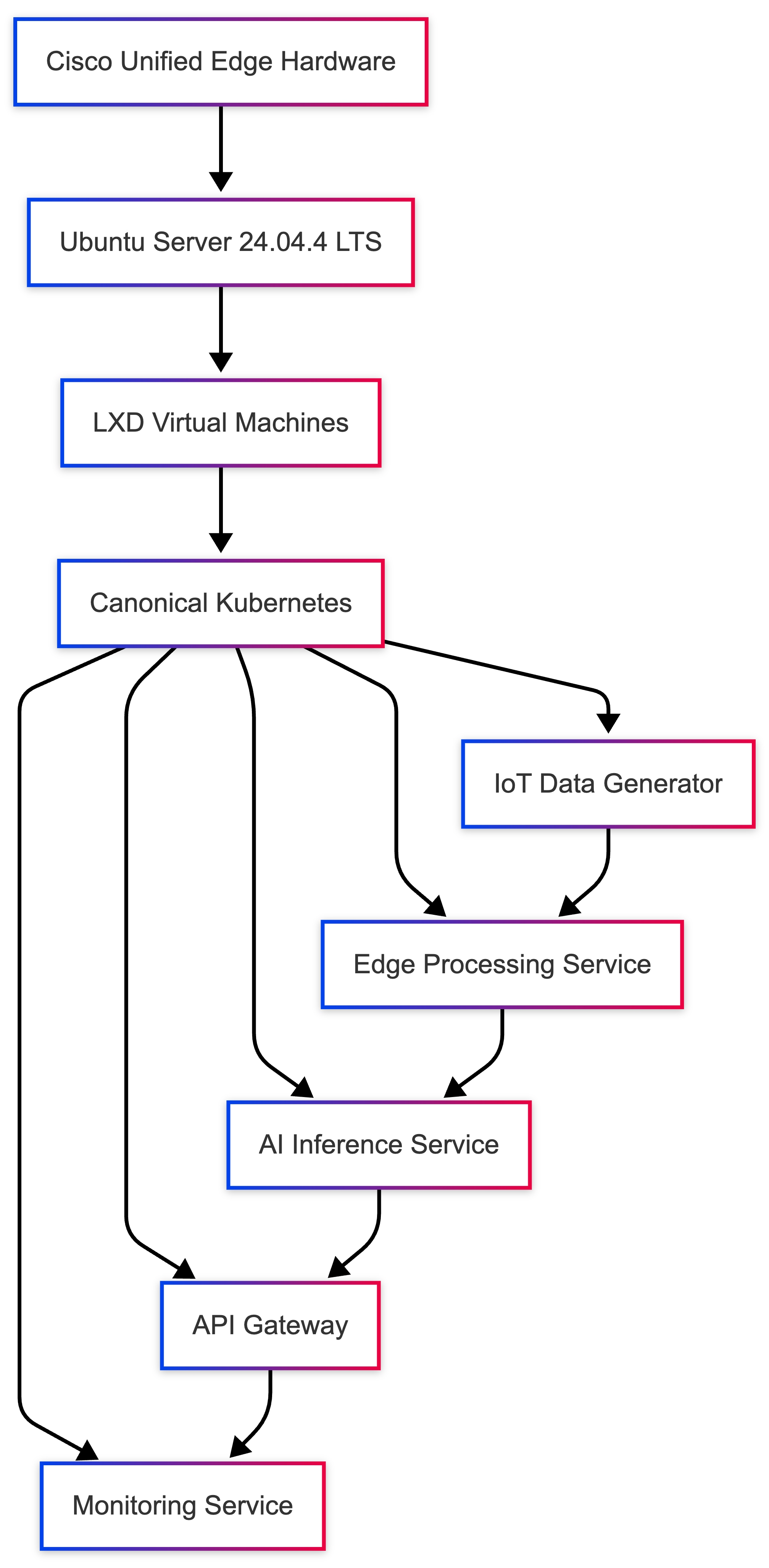
Edge computing environments frequently process data generated by IoT devices, sensors, cameras, and industrial equipment. Instead of sending all data to centralized cloud environments, edge platforms allow applications to process data locally, enabling lower latency, reduced bandwidth consumption, and improved operational responsiveness.
In this validated design, Canonical Kubernetes is used to deploy an example application that simulates an AI-enabled IoT processing pipeline running directly on the edge infrastructure.
The deployment validates the ability of the platform to host real-time data processing workloads, demonstrating the suitability of LXD and Canonical Kubernetes for edge environments.
Edge Application Architecture
The edge workload architecture consists of multiple components running as Kubernetes services.
Each component runs as a containerized service orchestrated by Kubernetes.
Workload Components
The example deployment includes the following microservices:
| Component |
Function |
| IoT Data Generator |
Simulates sensor data streams |
| Edge Processing Service |
Processes incoming data |
| AI Inference Service |
Performs basic analysis |
| API Gateway |
Exposes results |
| Monitoring Service |
Observes application metrics |
These services collectively represent a simplified edge analytics pipeline.
Kubernetes Deployment Model
The application is deployed using Kubernetes deployments and services.
This microservices architecture allows each service to scale independently.
Step 1 - Create Namespace
Create a dedicated namespace for the edge workload.
kubectl create namespace edge-workload
Namespaces isolate workloads and simplify cluster management.
Step 2 - Deploy IoT Data Generator
The IoT data generator simulates device telemetry.
Create the deployment:
kubectl create deployment iot-simulator \
--image=nginx \
-n edge-workload
Verify deployment:
kubectl get pods -n edge-workload
Expected output:
iot-simulator-xxxx Running
Step 3 - Deploy Edge Processing Service
Deploy a service that processes incoming IoT data.
kubectl create deployment edge-processor \
--image=python:3.11 \
-n edge-workload
This container represents an edge analytics service.
Step 4 - Deploy AI Inference Service
The AI service performs local data analysis.
kubectl create deployment ai-inference \
--image=python:3.11 \
-n edge-workload
In real deployments, this service would run models such as:
● object detection
● anomaly detection
● predictive maintenance
Step 5 - Deploy API Gateway
Expose the edge processing results through a service endpoint.
kubectl expose deployment edge-processor \
--type=NodePort \
--port=80 \
-n edge-workload
Verify service:
kubectl get svc -n edge-workload
Example output:
edge-processor NodePort 80:30080/TCP
The application can now be accessed via the node IP and assigned NodePort.
Workload Validation
Confirm that all services are running:
kubectl get pods -n edge-workload
Example output:
iot-simulator Running edge-processor Running ai-inference Running
This confirms that the edge workload pipeline is operational.
Edge Processing Workflow
Once deployed, the application workflow proceeds as follows:
● IoT devices generate telemetry data
● Data is ingested by the processing service
● AI inference analyzes the data
Results are exposed through an API endpointThis architecture enables real-time decision making at the edge.
Benefits of Edge Kubernetes Deployment
Running AI and IoT workloads locally provides several advantages.
Reduced Latency
Data processing occurs close to the source, enabling near real-time response.
Lower Network Utilization
Only processed results need to be transmitted to central systems.
Improved Reliability
Applications continue operating even when cloud connectivity is interrupted.
Scalability
Kubernetes enables dynamic scaling of edge workloads.
Edge Platform Operational Benefits
Deploying Kubernetes workloads on LXD VMs provides several operational advantages:
● rapid workload deployment
● efficient infrastructure utilization
● simplified cluster management
● dynamic workload scaling
The platform enables a consistent application deployment model across edge, data center, and cloud environments.
Design Considerations
When deploying AI or IoT workloads at the edge, the following factors should be considered.
Resource Allocation
Ensure sufficient CPU and memory are available for inference workloads.
Data Retention
Edge systems should implement policies for data storage and rotation.
Security
Secure communication between IoT devices and edge services.
Network Segmentation
Isolate operational technology (OT) networks from enterprise IT networks.
Validation Summary
The edge workload deployment successfully validated the following capabilities:
| Validation Test |
Result |
| Kubernetes workload deployment |
Successful |
| Service exposure |
Successful |
| Multi-service architecture |
Operational |
| Edge processing pipeline |
Functional |
Kubernetes + LXD VM Integration
Cisco Unified Edge – Container Orchestration Architecture
This section describes the validated integration model between a MicroCloud-based infrastructure platform and Canonical Kubernetes. In this architecture, LXD provides infrastructure-level virtualization and resource isolation, while Kubernetes provides container orchestration and application lifecycle management.
Architecture Overview
In an integrated deployment:
● Each Unified Edge node runs Ubuntu
● LXD provides container/VM hosting
● Kubernetes runs on top of LXD nodes
● Ceph (optional) provides shared storage
● Workloads are orchestrated by Kubernetes
Two primary models are supported.
Supported Integration Models
Kubernetes Directly on Host
Ubuntu Host
├── LXD (for system containers / VMs)
└── Kubernetes (container runtime = containerd)
Description
Kubernetes runs directly on the host OS.
LXD is used only for:
● Infrastructure containers
● Edge microservices
● Legacy workloads
● VM hosting
Advantages
● Clean separation of orchestration layers
● Best performance
● Lower networking complexity
● Simplified troubleshooting
Position
Supported for lab or CI environments, not recommended for production Unified Edge.
Recommended Production Deployment Flow
Step 1 — Prepare All Nodes
On every node:
snap install lxd
Ensure:
sysctl net.ipv4.ip_forward
sysctl net.bridge.bridge-nf-call-iptables
Return value = 1
Step 2 — Install Canonical Kubernetes
On all nodes:
sudo snap install k8s --classic --channel=1.35-classic/stable
Initialize the control plane on node1:
sudo k8s bootstrap
sudo k8s status --wait-ready
Generate join tokens for the remaining nodes from node1:
sudo k8s get-join-token <control-plane-node-name>
sudo k8s get-join-token <worker-node-name> --worker
Join each additional node with its token:
sudo k8s join-cluster <join-token>
Step 3 — Install CNI Plugin
Example (Flannel):
kubectl apply -f https://raw.githubusercontent.com/flannel-io/flannel/master/Documentation/kube-flannel.yml
Step 4 — Join Worker Nodes
On each worker node:
sudo k8s join-cluster <worker-join-token>
Networking Design Considerations
Avoid CIDR overlap:
| Component |
Example CIDR |
| LXD bridge |
10.132.0.0/24 |
| Kubernetes Pod CIDR |
10.244.0.0/16 |
| Kubernetes Service CIDR |
10.96.0.0/12 |
● Management VLAN
● Storage VLAN
● Enterprise LAN
Ceph + Kubernetes Integration
If MicroCeph is enabled in LXD cluster:
Install Ceph CSI driver:
kubectl apply -f ceph-csi-rbd.yaml
Create StorageClass:
apiVersion: storage.k8s.io/v1
kind: StorageClass
metadata:
name: ceph-rbd
provisioner: rbd.csi.ceph.com
parameters:
pool: cephpool
Now persistent volumes are shared across nodes.
High Availability Behavior
With:
● MicroCloud multi-node platform
● Kubernetes control plane HA
● Ceph distributed storage
The system supports:
● Pod rescheduling
● Node failure tolerance
● Stateful workloads
● Storage replication
Production Security Model
Recommended controls:
● Firewall restrict LXD API (8443)
● Firewall restrict Kubernetes API (6443)
● Enable RBAC
● Disable anonymous access
● Encrypt etcd
Performance Considerations
● Containerd recommended runtime
● Avoid running Kubernetes inside LXD VMs
● Dedicated CPU pinning optional
● Memory reservations recommended
Failure Scenario Example
If Node 2 fails:
● Kubernetes marks node NotReady
● Pods rescheduled to Node 1 or 3
● Ceph ensures persistent volume availability
Recommended Architecture Position
For Cisco Unified Edge:
| Deployment Size |
Recommended Model |
| Single node |
Kubernetes on host |
| 3-node HA |
Kubernetes on host + Ceph |
| Industrial HA |
Kubernetes + Ceph |
| AI cluster |
Kubernetes + Ceph |
Avoid:
● Nested Kubernetes inside LXD for production
Summary
In production Unified Edge deployments, Kubernetes should run directly on the host operating system, while LXD provides infrastructure-level virtualization for system containers and VM workloads. When combined with Ceph distributed storage, this architecture provides high availability, workload mobility, and scalable edge orchestration.
Standalone versus MicroCloud Deployment
This section compares standalone and MicroCloud deployment models to help determine the appropriate architecture for edge workload requirements.
Table 16. Architectural Comparison
| Category |
Standalone LXD |
MicroCloud |
| Number of Nodes |
Single node |
2+ nodes (3 recommended) |
| High Availability |
No |
Yes (with MicroCeph) |
| Workload Migration |
Not supported |
Supported (with MicroCeph) |
| Storage Model |
Local storage only |
Local or distributed storage |
| Cluster Database |
Not required |
Integrated distributed services |
| API Exposure |
Local only |
Platform-wide management |
| Operational Complexity |
Low |
Medium to High |
| Resource Overhead |
Minimal |
Higher |
| Network Requirements |
Basic |
Static IP + multicast/network coordination |
| Failure Tolerance |
Node failure = workload loss |
Workloads can recover across nodes |
Table 17. Storage Capabilities
| Feature |
Standalone |
MicroCloud |
| Local dir backend |
Yes |
Yes |
| ZFS backend |
Yes |
Yes |
| MicroCeph distributed storage |
No |
Yes |
| Shared persistent volumes |
No |
Yes |
| Live container migration |
No |
MicroCeph required |
Table 18. Edge Workload Suitability
| Deployment Type |
Standalone |
MicroCloud |
| Small retail site |
Recommended |
Not required |
| Industrial gateway |
Recommended |
Optional |
| AI inference node |
Yes |
Optional |
| Regional edge aggregation |
No |
Recommended |
| High availability edge |
No |
Required |
| Stateful applications |
Limited |
Recommended |
Table 19. Operational Considerations
| Factor |
Standalone |
MicroCloud |
| Setup time |
Fast |
Moderate |
| Maintenance complexity |
Low |
Higher |
| Upgrade coordination |
Single node |
Coordinated across nodes |
| Monitoring requirements |
Basic |
Platform-aware |
| Backup strategy |
Per-node |
Distributed platform-aware backup |
| Network dependency |
Low |
High |
| Scenario |
Standalone |
MicroCloud Without MicroCeph |
MicroCloud With MicroCeph |
| Single node failure |
All workloads lost |
Workloads lost |
Workloads recoverable |
| Storage failure |
Workloads lost |
Workloads lost |
Data replicated |
| Control plane failure |
N/A |
Platform degraded |
Platform remains operational |
| Component |
Standalone |
MicroCloud |
| CPU overhead |
Low |
Moderate |
| Memory overhead |
Low |
Higher |
| Storage overhead |
Minimal |
Replication overhead |
| Network overhead |
Low |
Storage replication traffic |
Standalone LXD versus MicroCloud versus Kubernetes-Only
This section compares three validated deployment models available for Unified Edge environments. The selection depends on workload type, availability requirements, operational complexity tolerance, and scalability needs.
Table 22. Architecture Overview
| Model |
Description |
| Standalone LXD |
Single-node LXD deployment hosting containers and/or VMs locally |
| MicroCloud |
Multi-node Canonical edge cloud platform integrating LXD, MicroOVN, and optional MicroCeph |
| Kubernetes-Only |
Kubernetes running directly on host OS without LXD abstraction |
Table 23. Core Capability Comparison
| Capability |
Standalone LXD |
MicroCloud |
Kubernetes-Only |
| Multi-node support |
No |
Yes |
Yes |
| High Availability |
No |
Yes (with MicroCeph) |
Yes |
| Workload Orchestration |
Limited |
Limited |
Advanced |
| Auto Rescheduling |
No |
Partial |
Yes |
| Stateful Workloads |
Limited |
Yes (with MicroCeph) |
Yes |
| Live Migration |
No |
MicroCeph required |
Pod rescheduling |
| VM Support |
Yes |
Yes |
No |
| Container Density |
High |
High |
High |
| Infrastructure Isolation |
Strong |
Strong |
Moderate |
| Operational Complexity |
Low |
Medium/High |
Medium |
Table 24. Storage Model Comparison
| Storage Feature |
Standalone LXD |
MicroCloud |
Kubernetes-Only |
| Local dir backend |
Yes |
Yes |
Yes |
| ZFS backend |
Yes |
Yes |
Optional |
| Distributed storage |
No |
Yes |
Yes (using CSI backend) |
| Persistent Volumes |
Limited |
Yes |
Yes |
| Shared Storage Across Nodes |
No |
Yes |
Yes |
Table 25. Networking Complexity
| Networking Aspect |
Standalone |
MicroCloud |
Kubernetes-Only |
| NAT Bridge |
Yes |
Yes |
N/A |
| Overlay Network |
No |
Yes |
Yes |
| CNI Plugin Required |
No |
No for infrastructure layer |
Yes |
| Static IP Requirement |
No |
No |
No |
| Port Requirements |
Minimal |
Platform networking requirements |
6443 + CNI |
Table 26. Edge Deployment Suitability
| Deployment Scenario |
Standalone LXD |
MicroCloud |
Kubernetes-Only |
| Retail single store |
Recommended |
No |
Optional |
| Small branch office |
Yes |
No |
Optional |
| Industrial gateway |
Yes |
Optional |
Yes |
| Regional edge aggregation |
No |
Recommended |
Recommended |
| AI inference cluster |
Yes |
Yes |
Recommended |
| High availability site |
No |
Yes |
Yes |
| Microservices-heavy workloads |
Limited |
Limited |
Recommended |
| Failure Scenario |
Standalone |
MicroCloud Without MicroCeph |
MicroCloud With MicroCeph |
Kubernetes-Only |
| Node failure |
All workloads lost |
Workloads lost |
Recoverable |
Pods rescheduled |
| Storage failure |
Data loss |
Data loss |
Replicated |
Depends on backend |
| Control plane failure |
N/A |
Platform degraded |
Platform degraded |
HA control plane required |
Table 28. Resource and Operational Impact
| Factor |
Standalone |
MicroCloud |
Kubernetes-Only |
| Memory overhead |
Low |
Medium/High |
Medium |
| CPU overhead |
Low |
Medium |
Medium |
| Storage overhead |
Minimal |
High (replication) |
Moderate |
| Upgrade coordination |
Simple |
Coordinated |
Coordinated |
| Skill requirement |
Basic Linux |
Advanced Linux |
Kubernetes expertise |
Full High Availability Edge Architecture
Architecture Overview
The full HA architecture consists of three or more Cisco Unified Edge nodes forming a clustered infrastructure that integrates:
● MicroCloud (infrastructure platform)
● MicroCeph distributed storage
● Kubernetes HA control plane
● Segmented networking for management, storage, and data
This architecture ensures workload continuity, storage resilience, and application-level high availability in edge environments.
Logical Architecture Layers
The following diagram illustrates a layered format.
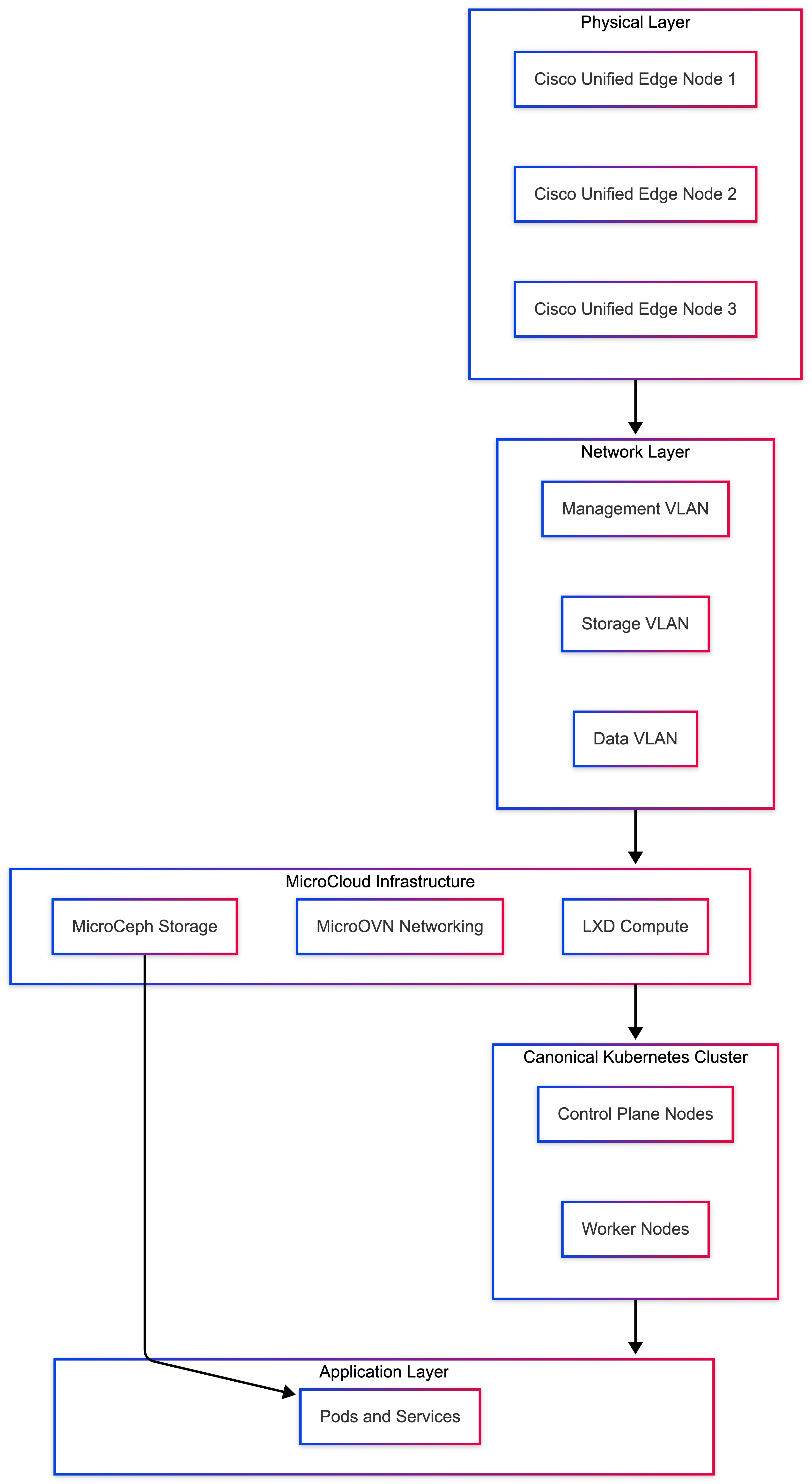
Layer 1 - Physical Layer (Cisco Unified Edge Nodes)
Minimum recommended:
● 3 Unified Edge nodes
● Dedicated OS disk
● Dedicated MicroCeph storage disk per node
● Redundant network interfaces
Each node runs:
● Ubuntu Server 24.04.4 LTS
● MicroCloud components
● Containerd
● Kubernetes components
● MicroCeph OSD
Layer 2 - Networking Segmentation
The architecture includes three logical networks:
| Network |
Purpose |
Example |
| Management VLAN |
MicroCloud and Kubernetes API |
192.168.10.0/24 |
| Storage VLAN |
MicroCeph replication traffic |
192.168.30.0/24 |
| Data VLAN |
Application traffic |
192.168.50.0/24 |
Separation ensures:
● MicroCeph replication does not affect application traffic
● Platform communication remains stable
● Traffic isolation improves security posture
Layer 3 - MicroCloud Infrastructure Layer
MicroCloud runs across all nodes and integrates:
● LXD for compute
● MicroOVN for networking
● Optional MicroCeph for storage
Platform characteristics:
● Integrated distributed services
● Shared trust model
● Centralized control
● Optional VM hosting
● Infrastructure container support
This layer provides infrastructure abstraction.
Layer 4 - MicroCeph Distributed Storage Layer
MicroCeph provides shared block storage across nodes.
Each node contributes:
● One OSD disk
MicroCeph characteristics:
● Replication factor = 3
● Data distributed across nodes
● No single storage point of failure
● Persistent volumes remain available during node failure
● MicroCeph traffic runs on the dedicated storage VLAN.
Layer 5 - Kubernetes HA Control Plane
Kubernetes runs directly on host OS or on top of the MicroCloud-managed platform, depending on the validated deployment model.
Control plane configuration:
● 3 control-plane nodes
● etcd quorum across nodes
● CNI overlay network
● Pod CIDR separate from LXD CIDR
Example:
| Component |
CIDR |
| LXD Bridge |
10.132.0.0/24 |
| Kubernetes Pod CIDR |
10.244.0.0/16 |
| Kubernetes Service CIDR |
10.96.0.0/12 |
Kubernetes provides:
● Pod scheduling
● Self-healing
● Rolling updates
● Auto rescheduling
● Failure Scenarios Explained
Scenario 1 - Single Node Failure
If Node 2 fails:
● MicroCeph rebalances data
● Kubernetes marks node NotReady
● Pods are rescheduled to Node 1 or 3
● Persistent volumes remain accessible
● No data loss occurs.
Scenario 2 - MicroCeph OSD Failure
If a storage disk fails:
● MicroCeph marks the OSD down
● Data is replicated from remaining copies
● The cluster remains operational
Scenario 3 - Control Plane Failure
If one control plane node fails:
● etcd quorum is maintained
● API remains available
● The cluster continues operating
Scenario 4 - Network Partition
If the storage VLAN is disrupted:
● MicroCeph may degrade
● Write performance may be impacted
● The cluster remains partially functional
● Network recovery is required
Traffic Flow Description
Container Startup Flow
● User deploys application via Kubernetes
● Scheduler selects available node
● Container runtime launches container
● Persistent volume is provisioned through MicroCeph CSI
● Pod receives overlay IP from CNI
● Traffic flows through the data VLAN
MicroCeph Replication Flow
● Write request sent to MicroCeph pool
● Data written to primary OSD
● Replicated to secondary and tertiary OSDs
● Acknowledgment returned after replication quorum
Table 29. Resource Isolation Model
| Layer |
Responsibility |
| Ubuntu |
Kernel and system services |
| MicroCloud |
Integrated infrastructure abstraction |
| Kubernetes |
Application orchestration |
| MicroCeph |
Distributed storage |
| CNI |
Pod networking |
Each layer operates independently but integrates through defined interfaces.
Table 30. High Availability Characteristics Summary
| Feature |
Supported |
| Node failure tolerance |
Yes |
| Storage replication |
Yes |
| Control plane HA |
Yes |
| Live container rescheduling |
Yes |
| Stateful workload protection |
Yes |
| Zero single point of failure |
Yes |
Operational Considerations
● Requires 3-node minimum
● Requires static IP addressing
● Requires storage VLAN
● Higher memory consumption
● Requires coordinated upgrades
● Monitoring must include MicroCeph and Kubernetes
Recommended Deployment Scenarios
● Full HA architecture is recommended for:
● industrial edge with strict uptime requirements
● Regional edge aggregation sites
● AI inference clusters
● Edge data processing clusters
● Smart city deployments
Not recommended for:
● Small retail sites
● Single-node edge
● Stateless micro-branch workloads
Summary
The full high-availability Unified Edge architecture integrates MicroCloud, MicroCeph distributed storage, and Kubernetes orchestration to eliminate single points of failure. This design ensures workload continuity, data resilience, and scalable orchestration while maintaining clear separation between infrastructure and application layers.
Canonical Kubernetes Installation for Edge Deployments
Edge deployments vary significantly depending on site size and workload requirements. The recommended Kubernetes architecture should match the operational requirements of the edge environment.
| Edge Environment |
Recommended Canonical Kubernetes Model |
| Small single-node edge |
Single control-plane node |
| Industrial high-availability edge |
Three-node HA control plane |
| Regional aggregation edge |
Three or more nodes with distributed storage |
Small branch locations often require minimal infrastructure, while larger industrial deployments require high availability and persistent storage capabilities.
Pre-Installation Requirements (All Nodes)
Before installing Canonical Kubernetes, the operating system must be prepared to support container runtime operations and cluster networking.
Disable Swap
Swap should be disabled for Kubernetes nodes to avoid scheduling and memory-management issues.
Disable swap immediately:
sudo swapoff -a
Disable swap permanently:
sudo sed -i '/ swap / s/^/#/' /etc/fstab
Install Canonical Kubernetes
Install Canonical Kubernetes on all nodes using the k8s snap:
sudo snap install k8s --classic --channel=1.35-classic/stable
This installs the Kubernetes components required for both control-plane and worker nodes.
Single-Node Edge Deployment
Single-node Kubernetes deployments are suitable for small retail sites, branch offices, or lightweight edge compute locations.
Bootstrap the cluster on the node:
sudo k8s bootstrap
sudo k8s status --wait-ready
Verify the node is ready:
sudo k8s kubectl get nodes
In single-node deployments, workloads run on the same node that hosts the control plane.
Multi-Node High Availability Deployment
For production edge environments requiring higher resilience, a multi-node Canonical Kubernetes cluster is recommended.
A typical high-availability architecture includes three control-plane nodes.
Step 1 - Bootstrap the First Control Plane
On node1:
sudo k8s bootstrap
sudo k8s status --wait-ready
This initializes the cluster and brings up the first control-plane node.
Step 2 - Join Additional Control Plane Nodes
On node1, generate join tokens for the additional control-plane nodes:
sudo k8s get-join-token node2
sudo k8s get-join-token node3
On node2 and node3, join the cluster using the generated tokens:
sudo k8s join-cluster <join-token>
These nodes participate in the control plane and help maintain cluster quorum.
Step 3 - Join Worker Nodes
Generate worker join tokens on an existing control-plane node:
sudo k8s get-join-token worker1 --worker
sudo k8s get-join-token worker2 --worker
On each worker node, join the cluster:
sudo k8s join-cluster <worker-join-token>
Worker nodes host the application workloads.
Cluster Networking
Canonical Kubernetes deploys its networking components as part of the cluster bootstrap process. Network ranges used by Kubernetes must not conflict with existing infrastructure networks.
Example recommended CIDR layout:
| Component |
Example Network |
| LXD bridge |
10.132.0.0/24 |
| Pod CIDR |
10.244.0.0/16 |
| Service CIDR |
10.96.0.0/12 |
| Management VLAN |
192.168.10.0/24 |
Careful network planning prevents routing conflicts and connectivity issues.
Distributed Storage Integration (Optional)
Stateful applications require persistent storage that remains available even if nodes fail.
For edge environments requiring resilient storage, distributed storage such as MicroCeph or another CSI-backed platform can be integrated with Canonical Kubernetes.
Example StorageClass structure:
kind: StorageClass
apiVersion: storage.k8s.io/v1
metadata:
name: ceph-rbd
provisioner: rbd.csi.ceph.com
Distributed storage ensures persistent volumes remain available across cluster nodes.
Edge Security Hardening
Production Kubernetes clusters should implement several security controls.
Recommended practices include:
● Enable Role-Based Access Control (RBAC)
● Restrict Kubernetes API access to the management VLAN
● Apply firewall rules for API access on port 6443
● Enable Kubernetes audit logging
● Limit administrative access to trusted operators
These measures help protect cluster infrastructure and workloads.
Edge Failure Behavior
Canonical Kubernetes provides automated recovery mechanisms.
If a worker node fails:
● pods are rescheduled
● services remain available
Persistent volumes remain accessible when using distributed storageIf a control-plane node fails in a three-node cluster:
● Quorum remains intact
● The cluster continues operating normally
Cluster Validation
Verify cluster health.
Check nodes:
sudo k8s kubectl get nodes
Check system pods:
sudo k8s kubectl get pods -A
Deploy a sample workload:
sudo k8s kubectl create deployment nginx --image=nginx
sudo k8s kubectl expose deployment nginx --type=NodePort --port=80
This confirms cluster scheduling and service networking.
Table 31. Recommended Deployment Model for Unified Edge
| Edge Deployment Type |
Recommended Architecture |
| Small retail edge |
Single-node cluster |
| Industrial HA edge |
Three-node control plane |
| AI processing cluster |
Three-node cluster with distributed storage |
| Regional aggregation edge |
HA Kubernetes cluster with distributed storage |
Selecting the appropriate architecture depends on workload criticality and site scale.
Summary
For production deployments on Cisco Unified Edge platforms, Canonical Kubernetes can be installed directly on the host operating system using the k8s snap.
Single-node deployments are well suited for small edge environments, while three-node high-availability clusters combined with distributed storage provide resilient orchestration capabilities for mission-critical edge workloads.
This architecture allows organizations to deploy cloud-native applications at the edge while maintaining scalability, operational control, and infrastructure resilience.
Single-Node MicroCloud Deployment
This section describes the deployment of MicroCloud on a single Cisco Unified Edge server running Ubuntu Server 24.04.4 LTS. MicroCloud is an integrated edge cloud platform that combines compute, networking, and storage services into a unified system.
A single-node MicroCloud deployment is commonly used for:
● Edge lab validation
● Development environments
● Proof-of-concept (PoC) deployments
● Platform familiarization
While production environments typically require three or more nodes for high availability, a single-node deployment provides a simplified environment to understand MicroCloud architecture, service integration, and operational workflows.
The deployment installs and integrates the following services:
| Component |
Function |
| LXD |
Container and virtual machine runtime |
| MicroOVN |
Software-defined networking |
| MicroCeph |
Distributed storage services |
| MicroCloud |
Orchestration and lifecycle management |
Architecture
The deployment follows a layered architecture model:
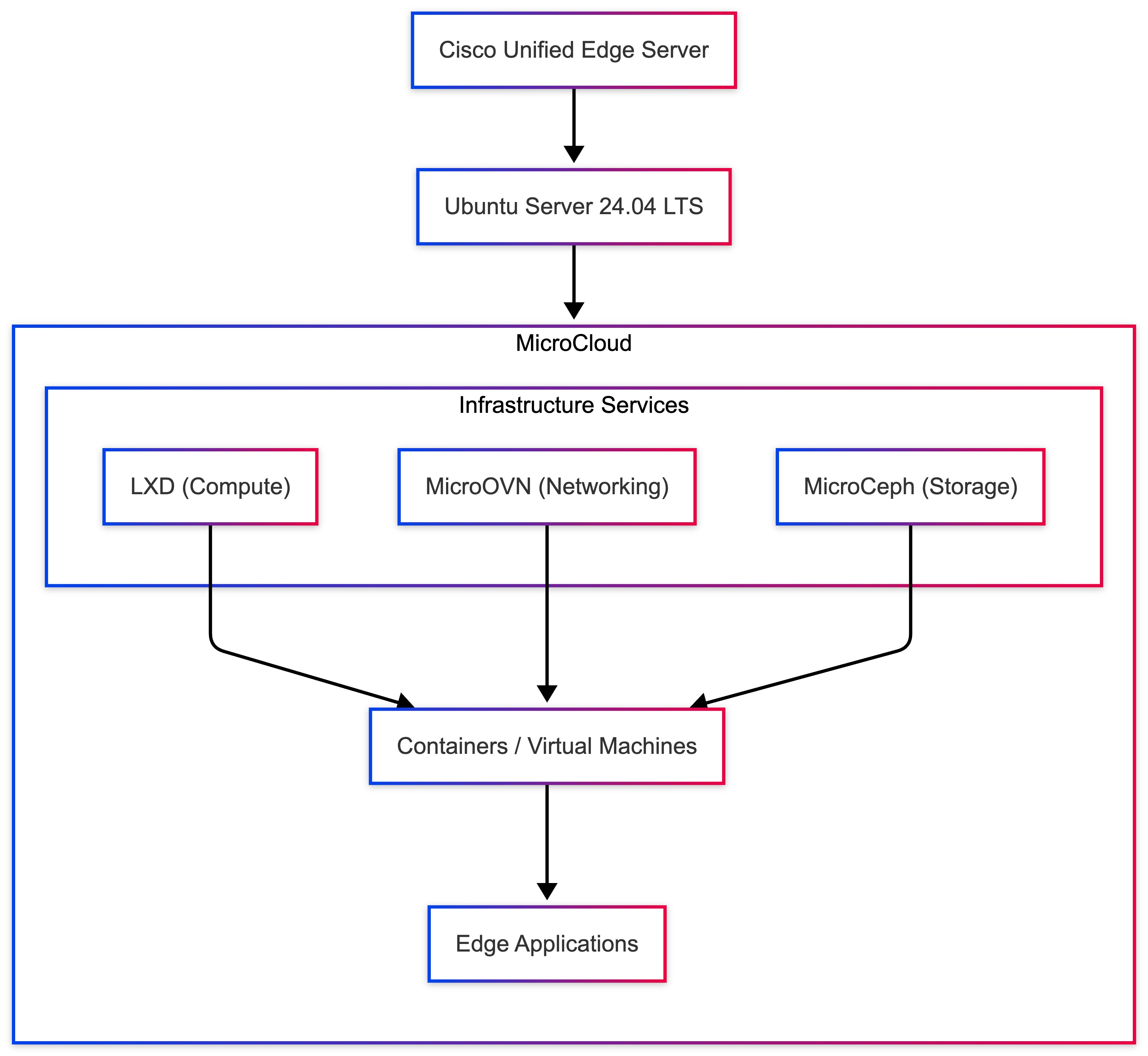
This architecture provides a lightweight private cloud platform capable of running containerized and virtualized workloads directly at the edge.
Network Requirements
Two network interfaces are required to separate internal platform communication from external access:
| Interface |
Purpose |
| Internal Network |
MicroCloud service communication |
| Uplink Network |
External connectivity |
The uplink network must support broadcast and multicast traffic, which is required for MicroCloud networking services.
Step 1 – Prepare Ubuntu Server
Update system packages to ensure the system is up to date.
sudo apt update && sudo apt upgrade -y
Set a hostname for the node.
sudo hostnamectl set-hostname edge-node1
Verify the hostname configuration.
hostnamectl
A consistent hostname is required for proper service identification within the platform.
Step 2 – Install MicroCloud Components
Install the required MicroCloud services using snap packages.
sudo snap install lxd --channel=5.21/stable
sudo snap install microceph --channel=squid/stable
sudo snap install microovn --channel=24.03/stable
sudo snap install microcloud --channel=2/stable
The cohort flag ensures version compatibility across nodes if the environment is later expanded into a multi-node cluster.
Step 3 – Hold Snap Updates
Pause automatic snap updates to maintain version consistency.
sudo snap refresh lxd microceph microovn microcloud --hold
This prevents unintended version mismatches between cluster services.
Step 4 – Initialize MicroCloud
Start the initialization process.
sudo microcloud init
The initialization process will guide you through configuration of networking, storage, and cluster setup.
Step 5 – Configure Cluster Membership
When prompted:
Do you want to set up more than one cluster member?
Select:
no
This configures MicroCloud in single-node mode, suitable for lab and development environments.
Step 6 – Configure Internal Network
MicroCloud automatically detects available interfaces and assigns an internal address.
Example:
Using address 10.132.0.15 for MicroCloud
This IP address is used for communication between MicroCloud services.
Step 7 – Configure Uplink Network
Select the interface providing external connectivity.
Example:
eno1np0
Provide the gateway:
10.132.0.1/24
Define the IP range for containers and virtual machines:
First IP: 10.132.0.200
Last IP: 10.132.0.250
This range will be used for dynamically assigned workload IP addresses.
Step 8 – Complete Initialization
MicroCloud initializes and configures all platform services.
Example output:
Initializing new services ...
Local MicroCloud is ready
Local MicroOVN is ready
Local MicroCeph is ready
Local LXD is ready
MicroCloud is ready
At this stage, the platform is fully operational.
Step 9 – Verify Deployment
Check MicroCloud status.
microcloud status
Example output:
Name Address
edge-node1 10.132.0.15
This confirms successful initialization.
Step 10 – Verify LXD Environment
Verify that LXD is operational.
lxc cluster list
Example output:
+-----------+--------------------------+
| NAME | URL |
+-----------+--------------------------+
| edge-node1| https://10.132.0.15:8443 |
+-----------+--------------------------+
Even in single-node mode, LXD operates with cluster capabilities enabled.
Step 11 – Deploy Test Container
Launch a test container to validate the environment.
lxc launch ubuntu:24.04.4 test-container
Verify container status.
lxc list
Example output:
NAME STATE IPV4
test-container RUNNING 10.200.10.5
This confirms that the compute platform is functioning correctly.
Step 12 – Access Web Interface
LXD provides a built-in web interface for management.
Open in browser:
https://<server-ip>:8443
Example:
https://10.132.0.15:8443
Use the current LXD web UI authentication flow documented for the validated LXD release. Generate the required access token or trust relationship using the latest LXD UI procedure for your environment.
Use the token to log in using the web interface.
| Test |
Expected Result |
| MicroCloud initialization |
Successful |
| LXD service status |
Running |
| Container deployment |
Successful |
| Web UI access |
Functional |
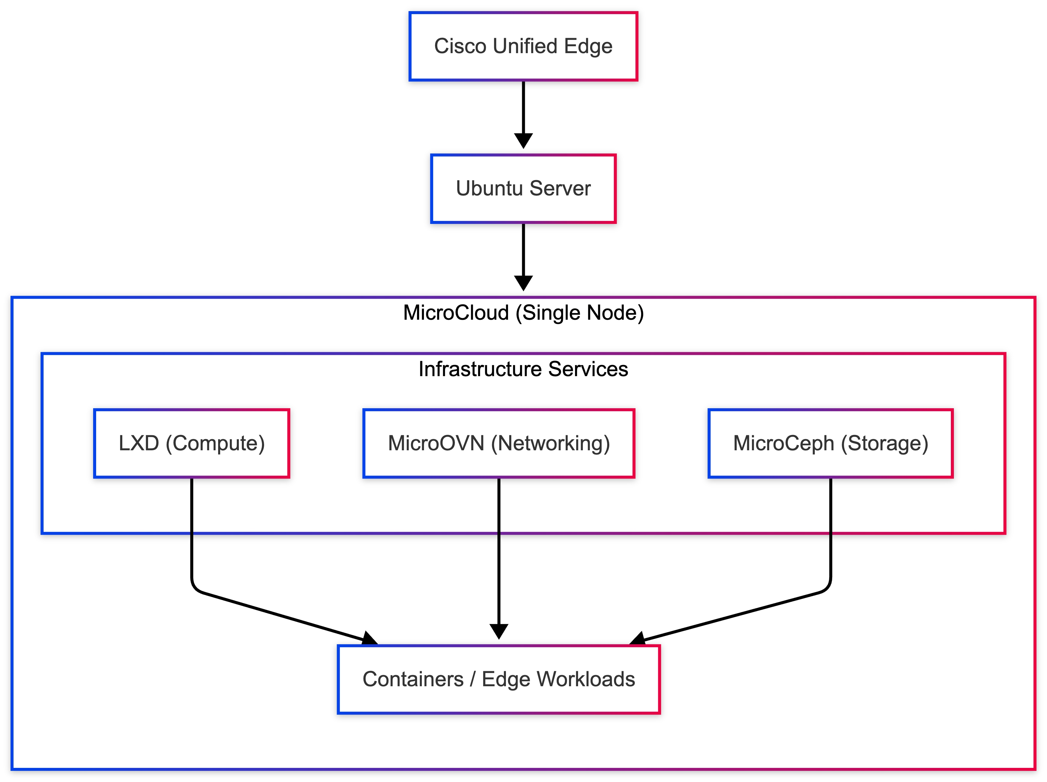
Summary
This deployment provides a lightweight private cloud platform for edge workloads, enabling rapid container and virtual machine deployment with integrated networking and storage.
Although this setup is designed for lab and development environments, it can be expanded into a multi-node MicroCloud cluster to support:
● high availability
● distributed storage
● workload migration
● scalable edge infrastructure
Multi-Node MicroCloud Deployment - 3-Node HA Cluster
This section describes the deployment of a highly available Kubernetes cluster on a 3-node MicroCloud platform running on Cisco Unified Edge servers.
In this architecture:
● MicroCloud provides the infrastructure layer
● LXD hosts Kubernetes nodes as containers
● MicroOVN enables cross-node networking
● Canonical Kubernetes orchestrates workloads
A 3-node Kubernetes deployment ensures:
● Control plane quorum
● Improved fault tolerance
● Distributed workload execution
● High availability for edge applications
This architecture is suitable for:
● Industrial edge platforms
● AI inference clusters
● Real-time analytics systems
● Mission-critical microservices
Architecture
Figure 10 illustrates the Cisco Unified Edge Cluster architecture.
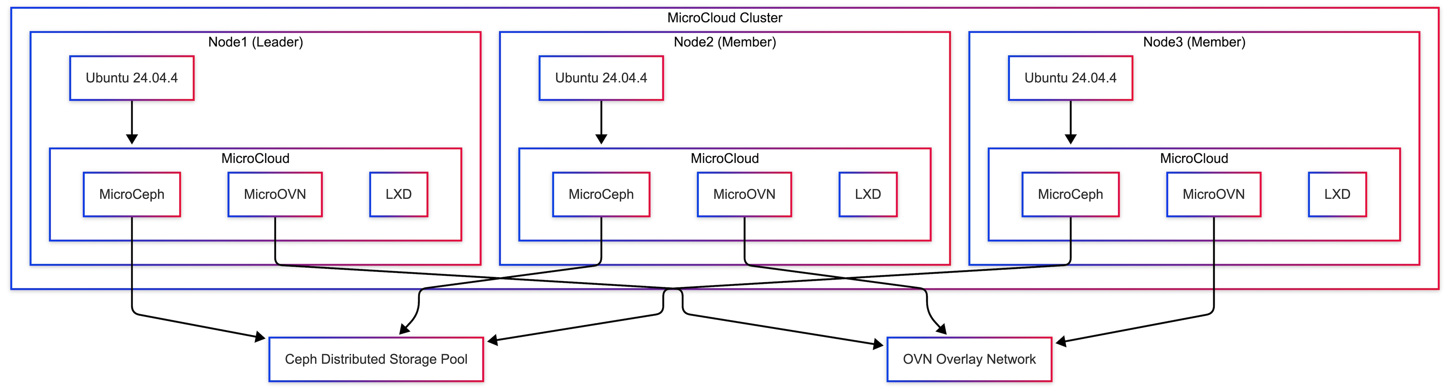
Cisco Unified Edge Cluster (3 Nodes)
Architecture Characteristics
● Kubernetes control plane distributed across 3 nodes
● LXD VMs act as Kubernetes nodes
● OVN overlay networking enables cross-node communication
● Kubernetes scheduler distributes workloads
● No single point of failure
| Requirement |
Status |
| MicroCloud 3-node cluster deployed |
Yes |
| LXD cluster operational |
Yes |
| MicroOVN networking configured |
Yes |
| Cross-node connectivity verified |
Yes |
Verify:
lxc cluster list
Step 1 - Create Kubernetes Node Containers
Deploy Kubernetes nodes as LXD VMs across all nodes.
Control plane nodes:
lxc launch ubuntu:24.04.4 k8s-control-1 --target node1
lxc launch ubuntu:24.04.4 k8s-control-2 --target node2
lxc launch ubuntu:24.04.4 k8s-control-3 --target node3
Worker nodes:
lxc launch ubuntu:24.04.4 k8s-worker1 --target node1
lxc launch ubuntu:24.04.4 k8s-worker2 --target node2
Verify:
lxc list
Step 2 - Install Canonical Kubernetes on First Control Plane
lxc exec k8s-control-1 -- bash
sudo snap install k8s --classic --channel=1.35-classic/stable
sudo k8s bootstrap
sudo k8s status --wait-ready
If DNS or local storage were disabled during bootstrap customization, enable them explicitly:
sudo k8s enable dns
sudo k8s enable local-storage
Step 3 - Generate Join Tokens
On k8s-control-1, generate tokens for the remaining nodes:
sudo k8s get-join-token k8s-control-2
sudo k8s get-join-token k8s-control-3
sudo k8s get-join-token k8s-worker1 --worker
sudo k8s get-join-token k8s-worker2 --worker
This produces join tokens for control-plane and worker nodes.
Step 4 - Join Additional Control Plane Nodes
On k8s-control-2:
lxc exec k8s-control-2 -- bash
sudo snap install k8s --classic --channel=1.35-classic/stable
sudo k8s join-cluster <control-plane-token-for-k8s-control-2>
On k8s-control-3:
lxc exec k8s-control-3 -- bash
sudo snap install k8s --classic --channel=1.35-classic/stable
sudo k8s join-cluster <control-plane-token-for-k8s-control-3>
Step 5 - Join Worker Nodes
On k8s-worker1:
lxc exec k8s-worker1 -- bash
sudo snap install k8s --classic --channel=1.35-classic/stable
sudo k8s join-cluster <worker-token-for-k8s-worker1>
On k8s-worker2:
lxc exec k8s-worker2 -- bash
sudo snap install k8s --classic --channel=1.35-classic/stable
sudo k8s join-cluster <worker-token-for-k8s-worker2>
Step 6 - Verify Kubernetes Cluster
On the first control plane node:
lxc exec k8s-control-1 -- bash
sudo k8s kubectl get nodes
Expected:
NAME STATUS ROLES
k8s-control-1 Ready control-plane,worker
k8s-control-2 Ready control-plane,worker
k8s-control-3 Ready control-plane,worker
k8s-worker1 Ready worker
k8s-worker2 Ready worker
Step 7 - Deploy Test Application
sudo k8s kubectl create deployment nginx --image=nginx
sudo k8s kubectl scale deployment nginx --replicas=3
Verify distribution:
sudo k8s kubectl get pods -o wide
Pods should run on different nodes.
Step 8 - Expose Application
sudo k8s kubectl expose deployment nginx --type=NodePort --port=80
sudo k8s kubectl get svc
Access:
curl http://<node-ip>:<nodeport>
Table 34. High Availability Behavior
| Failure Scenario |
Behavior |
| Single control plane failure |
Cluster continues |
| Worker node failure |
Pods rescheduled |
| Container failure |
Restarted automatically |
| Network disruption |
OVN maintains connectivity |
Production Recommendations
● Use kube-vip for a stable API endpoint
● Use MicroCeph for persistent storage
● Separate management and storage networks
● Enable monitoring and logging
● Avoid CIDR overlap between the LXD network, pod network, and service network
| Component |
Status |
| Control plane HA |
Yes |
| Worker nodes joined |
Yes |
| Pod scheduling |
Yes |
| Cross-node communication |
Yes |
| Application access |
Yes |
Summary
A 3-node Kubernetes cluster was successfully deployed on MicroCloud, providing:
● High availability control plane
● Distributed workload execution
● Resilient edge infrastructure
● Scalable Kubernetes platform
This architecture forms a production-ready edge cloud solution capable of supporting mission-critical workloads in distributed environments.
Multi-Node Kubernetes Cluster Deployment using Canonical Kubernetes
This section describes the deployment of a multi-node Kubernetes cluster using Canonical Kubernetes running on Cisco Unified Edge systems.
A multi-node Kubernetes architecture provides high availability, workload distribution, and improved fault tolerance for applications running in edge environments. By distributing Kubernetes nodes across multiple hosts, the platform can continue operating even if individual nodes experience failures.
Canonical Kubernetes is a lightweight, production-ready Kubernetes distribution developed by Canonical and optimized for edge and resource-constrained environments. It offers a simplified operational model while maintaining compatibility with standard Kubernetes APIs and tooling.
In this validated deployment architecture, each Kubernetes node runs on infrastructure distributed across multiple Cisco Unified Edge hosts. This design provides:
● Infrastructure isolation
● Flexible workload placement
● Efficient resource utilization
● Rapid node provisioning
The architecture allows organizations to deploy cloud-native workloads directly at the edge while maintaining centralized orchestration capabilities.
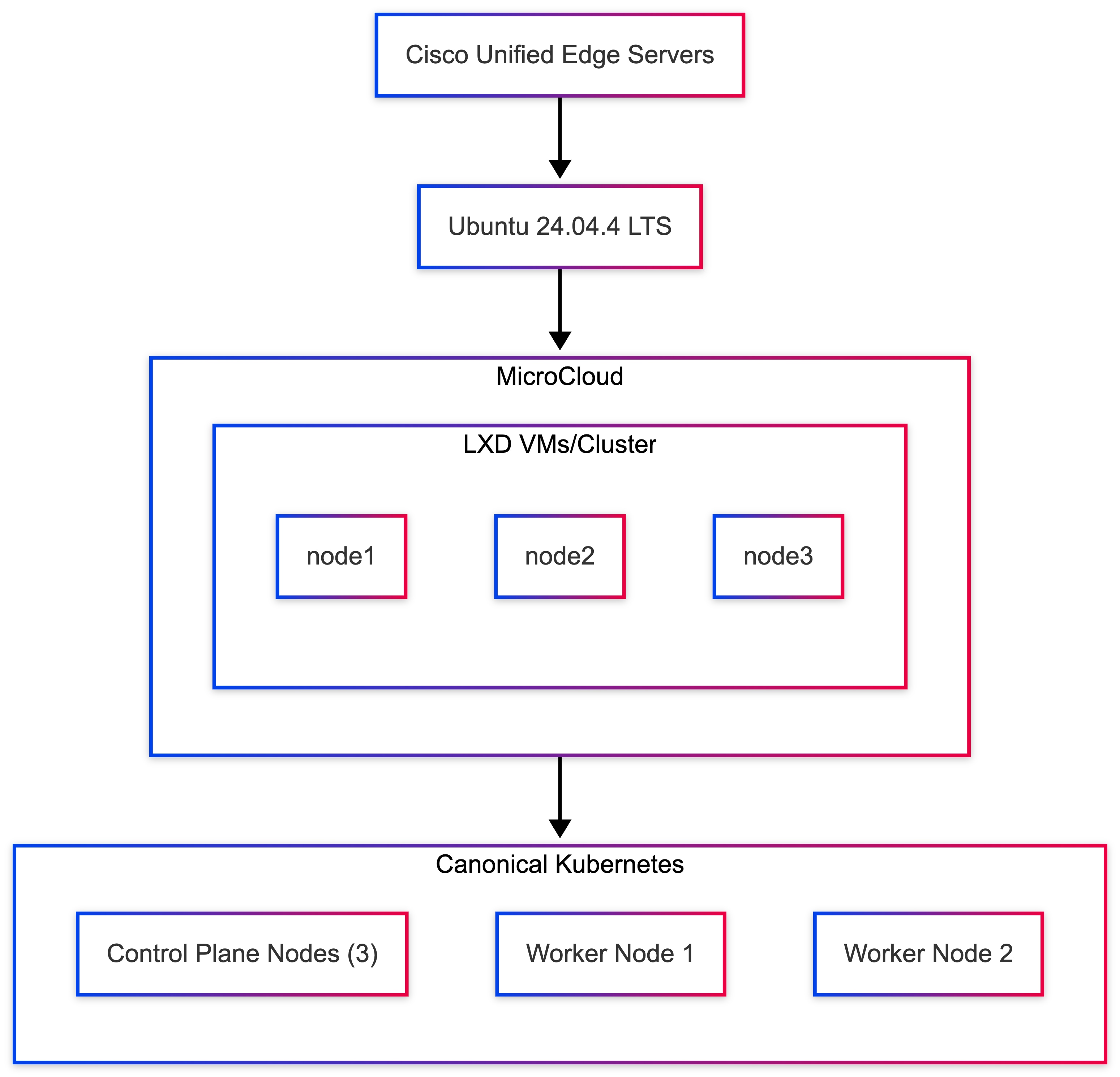
The Kubernetes cluster runs across multiple Cisco Unified Edge systems with Ubuntu Server 24.04.4 LTS as the operating system foundation.
This design ensures that Kubernetes nodes are distributed across multiple physical systems, improving resiliency and enabling workload failover capabilities.
Kubernetes Node Layout
Table 36 lists the node layout used in this validated deployment.
Table 36. Kubernetes Node Layout
| Node |
Role |
Host Node |
| k8s-control-plane1 |
Kubernetes control plane |
node1 |
| k8s-control-plane2 |
Kubernetes control plane |
node2 |
| k8s-control-plane3 |
Kubernetes control plane |
node3 |
| k8s-worker1 |
Worker node |
node2 |
| k8s-worker2 |
Worker node |
node3 |
The control plane nodes manage cluster state, API availability, and scheduling decisions, while worker nodes execute application workloads.
Deploy Kubernetes Nodes
The Kubernetes nodes are deployed across the available Cisco Unified Edge hosts.
Create Control Plane Nodes
lxc launch ubuntu:24.04.4 k8s-control-plane1 -p default -p canonical-k8s --target node1
lxc launch ubuntu:24.04.4 k8s-control-plane2 -p default -p canonical-k8s --target node2
lxc launch ubuntu:24.04.4 k8s-control-plane3 -p default -p canonical-k8s --target node3
Create Worker Nodes
lxc launch ubuntu:24.04.4 k8s-worker1 -p default -p canonical-k8s --target node2
lxc launch ubuntu:24.04.4 k8s-worker2 -p default -p canonical-k8s --target node3
Verify Node Deployment
lxc list
Expected output:
| Name |
State |
| k8s-control-plane1 |
RUNNING |
| k8s-control-plane2 |
RUNNING |
| k8s-control-plane3 |
RUNNING |
| k8s-worker1 |
RUNNING |
| k8s-worker2 |
RUNNING |
Install Canonical Kubernetes on the First Control Plane Node
Access the first control plane node:
lxc exec k8s-control-plane1 -- bash
Install Canonical Kubernetes:
snap install k8s --classic
Bootstrap the node:
sudo k8s bootstrap
sudo k8s status --wait-ready
This initializes the first control plane node and ensures Kubernetes services are running.
Install Canonical Kubernetes on Additional Nodes
Access each remaining node and install Canonical Kubernetes:
lxc exec k8s-control-plane2 -- bash
snap install k8s --classic
lxc exec k8s-control-plane3 -- bash
snap install k8s --classic
lxc exec k8s-worker1 -- bash
snap install k8s --classic
lxc exec k8s-worker2 -- bash
snap install k8s --classic
Join Additional Nodes to the Cluster
After the first control plane node is initialized, use Canonical Kubernetes cluster join procedures to add the remaining control plane and worker nodes.
Join the second and third control plane nodes to extend control plane quorum and high availability.
Join the worker nodes so they can host application workloads.
After all nodes join successfully, the cluster forms a distributed multi-node Kubernetes environment.
Verify Kubernetes Cluster
Return to the primary control plane node and verify cluster node status:
kubectl get nodes
Expected output:
| Node |
Status |
| k8s-control-plane1 |
Ready |
| k8s-control-plane2 |
Ready |
| k8s-control-plane3 |
Ready |
| k8s-worker1 |
Ready |
| k8s-worker2 |
Ready |
The Kubernetes cluster is now operational.
Deploy Sample Application
To validate cluster scheduling and networking, deploy a sample nginx application:
kubectl create deployment nginx --image=nginx
Scale the deployment:
kubectl scale deployment nginx --replicas=3
Verify pod distribution:
kubectl get pods -o wide
Pods should be scheduled across multiple worker nodes.
Validate Service Access
Expose the nginx application as a Kubernetes service:
kubectl expose deployment nginx --type=NodePort --port=80
Check service information:
kubectl get svc
The application should now be accessible via the assigned NodePort using the IP address of any cluster node.
High Availability Benefits
Deploying Kubernetes across multiple nodes provides significant operational advantages.
| Capability |
Benefit |
| Control-plane quorum |
Cluster survives single-node failure |
| Node redundancy |
Workloads remain available during node failures |
| Horizontal scaling |
Additional worker nodes can be added dynamically |
| Load distribution |
Pods are scheduled across multiple nodes |
| Self-healing |
Failed containers are automatically restarted |
These capabilities significantly improve reliability and scalability for edge workloads.
Operational Considerations
For production deployments, the following practices are recommended:
● Deploy three control-plane nodes for quorum-based high availability
● Implement persistent storage solutions for stateful workloads
● Define resource limits and quotas for workloads
● Deploy monitoring and logging solutions for cluster observability
These practices ensure long-term stability and operational visibility of the Kubernetes platform.
Validation Summary
A multi-node Kubernetes cluster was successfully deployed using Canonical Kubernetes on Cisco Unified Edge infrastructure.
The following capabilities were validated:
| Validation Test |
Result |
| Kubernetes node deployment |
Successful |
| Cluster formation |
Successful |
| Multi-node workload scheduling |
Successful |
| Service exposure via NodePort |
Successful |
The deployment demonstrates that Cisco Unified Edge platforms can host distributed Kubernetes clusters capable of orchestrating modern cloud-native workloads at the network edge.
High-Availability Kubernetes with kube-vip on MicroCloud Edge Cluster
This section describes the deployment of a high-availability Kubernetes control plane using kube-vip on a 3-node MicroCloud cluster running on Cisco Unified Edge servers.
In this architecture:
● MicroCloud provides distributed infrastructure
● LXD VMs host Kubernetes nodes
● MicroOVN enables cross-node networking
● kube-vip provides a Virtual IP (VIP) for API server high availability
The VIP acts as a single stable endpoint for the Kubernetes API server, ensuring uninterrupted access even if a control plane node fails.
Architecture Characteristics:
● 3 control-plane nodes for quorum
● kube-vip provides floating VIP ownership
● Leader election ensures VIP ownership
● Automatic failover on node failure
● No external load balancer required
| Requirement |
Status |
| MicroCloud 3-node cluster |
Yes |
| LXD cluster operational |
Yes |
| MicroOVN networking configured |
Yes |
| Cross-node connectivity validated |
Yes |
| Kubernetes containers created |
Yes |
Verify:
lxc cluster list
Step 1 - Deploy Kubernetes Control Plane Containers
lxc launch ubun¸tu:24.04.4 k8s-control-1 --target node1
lxc launch ubuntu:24.04.4 k8s-control-2 --target node2
lxc launch ubuntu:24.04.4 k8s-control-3 --target node3
Optional workers:
lxc launch ubuntu:24.04.4 k8s-worker1 --target node1
lxc launch ubuntu:24.04.4 k8s-worker2 --target node2
Step 2 - Install Canonical Kubernetes and Form the Cluster
On k8s-control-1:
lxc exec k8s-control-1 -- bash
sudo snap install k8s --classic --channel=1.35-classic/stable
sudo k8s bootstrap sudo k8s status --wait-ready
Generate join tokens:
sudo k8s get-join-token k8s-control-2
sudo k8s get-join-token k8s-control-3
sudo k8s get-join-token k8s-worker1 --worker
sudo k8s get-join-token k8s-worker2 --worker
Join k8s-control-2 and k8s-control-3:
lxc exec k8s-control-2 -- bash
sudo snap install k8s --classic --channel=1.35-classic/stable
sudo k8s join-cluster <control-plane-token-for-k8s-control-2>
lxc exec k8s-control-3 -- bash
sudo snap install k8s --classic --channel=1.35-classic/stable
sudo k8s join-cluster <control-plane-token-for-k8s-control-3>
Join workers:
lxc exec k8s-worker1 -- bash
sudo snap install k8s --classic --channel=1.35-classic/stable
sudo k8s join-cluster <worker-token-for-k8s-worker1>
lxc exec k8s-worker2 -- bash
sudo snap install k8s --classic --channel=1.35-classic/stable
sudo k8s join-cluster <worker-token-for-k8s-worker2>
Step 3 - Deploy kube-vip
On k8s-control-1:
export VIP=10.132.0.200 export INTERFACE=eth0
sudo k8s kubectl apply -f https://kube-vip.io/manifests/rbac.yaml
sudo k8s kubectl apply -f kube-vip.yaml
The kube-vip deployment advertises the VIP and performs leader election across control-plane nodes.
Step 4 - Verify HA Cluster
sudo k8s kubectl get nodes
Expected:
k8s-control-1 Ready
k8s-control-2 Ready
k8s-control-3 Ready
Verify VIP:
ip a | grep 10.132.0.200
Step 5 - Validate Failover
Simulate failure:
lxc stop k8s-control-1
Verify:
sudo k8s kubectl get nodes
Expected behavior:
● cluster remains accessible
VIP moves to another control plane node
Step 6 - Deploy Test Application
sudo k8s kubectl create deployment nginx --image=nginx
sudo k8s kubectl expose deployment nginx --type=NodePort --port=80
sudo k8s kubectl get svc
Table 38. High Availability Behavior
| Failure Scenario |
Behavior |
| Control plane node failure |
VIP moves automatically |
| API server failure |
No downtime |
| Worker node failure |
Pods rescheduled |
| Network interruption |
OVN maintains connectivity |
| Test |
Result |
| Control plane HA |
Yes |
| VIP active |
Yes |
| API accessible via VIP |
Yes |
| Failover working |
Yes |
| Workload deployment |
Yes |
Benefits of HA Kubernetes at the Edge
● No external load balancer required
● Automatic control plane failover
● Single stable API endpoint
● Resilient infrastructure for edge workloads
● Scalable Kubernetes deployment model
Production Recommendations
● Always use a minimum of 3 control-plane nodes
● Combine with MicroCeph for persistent storage
● Use a dedicated network for storage traffic
● Secure API server access on port 6443
● Enable monitoring and logging
Summary
A high-availability Kubernetes cluster using kube-vip was successfully deployed on a MicroCloud platform. The solution provides a self-contained, resilient Kubernetes control plane optimized for edge environments without requiring external load balancers.
This architecture is ideal for:
● industrial edge systems
● AI/ML inference platforms
● mission-critical distributed applications
Ulrich Kleidon, Principal Engineer, UCS Solutions, Cisco Systems, Inc.
Ulrich is a Principal Engineer for the Cisco UCS solutions team and a lead architect for solutions around converged infrastructure stacks, enterprise applications, data protection, software-defined storage, and Hybrid-Cloud. He has over 25 years of experience designing, implementing, and operating solutions in the data center.
Vinayaka Shivanna, Technical Marketing Engineer, UCS Solutions, Cisco Systems, Inc.
Vinayaka is a Technical Marketing Engineer on the Cisco Compute team. He has over six years of experience in the technology industry. Vinayaka has a strong background as a Full-Stack developer and AI engineer, with hands-on expertise in building and delivering AI-driven solutions across multiple domains. At Cisco, Vinayaka focuses on showcasing and enabling innovative compute and infrastructure capabilities, including Cisco UCS and AI integrations.
Acknowledgements
For their support and contribution to the design, validation, and creation of this Cisco Validated Design, the authors would like to thank:
● Chris O’Brien, Director for Technical Marketing, UCS Solutions, Cisco Systems, Inc.
● Miona Aleksic, Product Manager, MicroCloud, Canonical
● Enrico Panetta, Alliance Field Engineer, Canonical
Appendix
This appendix contains the following:
● Compute
● NVIDIA
Cisco Intersight: https://www.intersight.com
Cisco Intersight Managed Mode: https://www.cisco.com/c/en/us/td/docs/unified_computing/Intersight/b_Intersight_Managed_Mode_Configuration_Guide.html
Cisco Unified Edge and Canonical Ubuntu for Edge Deployments Design Guide: https://www.cisco.com/c/en/us/td/docs/unified_computing/ucs/UCS_documents/Cisco_Unified_Edge_and_Canonical_Ubuntu_for_Edge_Deployments_Design.html
Cisco Unified Edge At a Glance: https://www.cisco.com/c/en/us/products/collateral/servers-unified-computing/unified-edge/unified-edge-at-a-glance.html
Unified Edge Solution Overview: https://www.cisco.com/c/en/us/products/collateral/servers-unified-computing/unified-edge/unified-edge-solution-overview.html
Canonical Kubernetes: https://documentation.ubuntu.com/canonical-kubernetes/latest/
Canonical MicroCloud: https://documentation.ubuntu.com/microcloud/v2-edge/microcloud/
Canonical LXD: https://documentation.ubuntu.com/microcloud/v2-edge/lxd/
Canonical MicroCeph: https://documentation.ubuntu.com/microcloud/v2-edge/microceph/
Canonical MicroOVN: https://documentation.ubuntu.com/microcloud/v2-edge/microovn/
Canonical Ubuntu Core: https://documentation.ubuntu.com/core/
Canonical Ubuntu Server: https://documentation.ubuntu.com/server/
NVIDIA L4 GPU: https://www.nvidia.com/en-in/data-center/l4/
NVAIE: https://www.nvidia.com/en-in/data-center/products/ai-enterprise/
NVAIE Product Support Matrix: https://docs.nvidia.com/ai-enterprise/latest/product-support-matrix/index.html#support-matrix__suse-linux-enterprise-server
Cisco UCS Hardware Compatibility Matrix: https://ucshcltool.cloudapps.cisco.com/public/
CVD Program
ALL DESIGNS, SPECIFICATIONS, STATEMENTS, INFORMATION, AND RECOMMENDATIONS (COLLECTIVELY, "DESIGNS") IN THIS MANUAL ARE PRESENTED "AS IS," WITH ALL FAULTS. CISCO AND ITS SUPPLIERS DISCLAIM ALL WARRANTIES, INCLUDING, WITHOUT LIMITATION, THE WARRANTY OF MERCHANTABILITY, FITNESS FOR A PARTICULAR PURPOSE AND NONINFRINGEMENT OR ARISING FROM A COURSE OF DEALING, USAGE, OR TRADE PRACTICE. IN NO EVENT SHALL CISCO OR ITS SUPPLIERS BE LIABLE FOR ANY INDIRECT, SPECIAL, CONSEQUENTIAL, OR INCIDENTAL DAMAGES, INCLUDING, WITHOUT LIMITATION, LOST PROFITS OR LOSS OR DAMAGE TO DATA ARISING OUT OF THE USE OR INABILITY TO USE THE DESIGNS, EVEN IF CISCO OR ITS SUPPLIERS HAVE BEEN ADVISED OF THE POSSIBILITY OF SUCH DAMAGES.
THE DESIGNS ARE SUBJECT TO CHANGE WITHOUT NOTICE. USERS ARE SOLELY RESPONSIBLE FOR THEIR APPLICATION OF THE DESIGNS. THE DESIGNS DO NOT CONSTITUTE THE TECHNICAL OR OTHER PROFESSIONAL ADVICE OF CISCO, ITS SUPPLIERS OR PARTNERS. USERS SHOULD CONSULT THEIR OWN TECHNICAL ADVISORS BEFORE IMPLEMENTING THE DESIGNS. RESULTS MAY VARY DEPENDING ON FACTORS NOT TESTED BY CISCO.
CCDE, CCENT, Cisco Eos, Cisco Lumin, Cisco Nexus, Cisco StadiumVision, Cisco TelePresence, Cisco WebEx, the Cisco logo, DCE, and Welcome to the Human Network are trademarks; Changing the Way We Work, Live, Play, and Learn and Cisco Store are service marks; and Access Registrar, Aironet, AsyncOS, Bringing the Meeting To You, Catalyst, CCDA, CCDP, CCIE, CCIP, CCNA, CCNP, CCSP, CCVP, Cisco, the Cisco Certified Internetwork Expert logo, Cisco IOS, Cisco Press, Cisco Systems, Cisco Systems Capital, the Cisco Systems logo, Cisco Unified Computing System (Cisco UCS), Cisco UCS B-Series Blade Servers, Cisco UCS C-Series Rack Servers, Cisco UCS S-Series Storage Servers, Cisco UCS X-Series, Cisco UCS Manager, Cisco UCS Management Software, Cisco Unified Fabric, Cisco Application Centric Infrastructure, Cisco Nexus 9000 Series, Cisco Nexus 7000 Series. Cisco Prime Data Center Network Manager, Cisco NX-OS Software, Cisco MDS Series, Cisco Unity, Collaboration Without Limitation, EtherFast, EtherSwitch, Event Center, Fast Step, Follow Me Browsing, FormShare, GigaDrive, HomeLink, Internet Quotient, IOS, iPhone, iQuick Study, LightStream, Linksys, MediaTone, MeetingPlace, MeetingPlace Chime Sound, MGX, Networkers, Networking Academy, Network Registrar, PCNow, PIX, PowerPanels, ProConnect, ScriptShare, SenderBase, SMARTnet, Spectrum Expert, StackWise, The Fastest Way to Increase Your Internet Quotient, TransPath, WebEx, and the WebEx logo are registered trade-marks of Cisco Systems, Inc. and/or its affiliates in the United States and certain other countries. (LDW_P5)
All other trademarks mentioned in this document or website are the property of their respective owners. The use of the word partner does not imply a partnership relationship between Cisco and any other company. (0809R)